Firmtech FZ200BS ZIGBEE USB ADAPTER User Manual
Firmtech co., Ltd ZIGBEE USB ADAPTER Users Manual
UserManual.wiki
>
Firmtech
>
FZ200BS User Manual
Users Manual
Navigation menu
Upload a User Manual
Namespaces
Wiki Guide
HTML
PDF
Info
Views
User Manual
Discussion / Help
Navigation
![FZ200BS Manual VERSION 0.1.0 10through the OK/ERROR LED. (12) FZ200BS has an IEEE ADDRESS and a NETWORK ADDRESS. 64 Bit IEEE ADDRESS is a physical address of FZ200BS. Every device has its own IEEE ADDRESS and the IEEE ADDRESS is not changeable. FZ200BS set target devices by using IEEE ADDRESS. In conclusion, “target device set-up” is an inquiry using IEEE ADDRESS for NETWORK ADDRESS of its target devices FZ200BS has a 16 Bit of NETWORK ADDRESS for the Zigbee Network communication. NETWORK ADDRESS is given when FZ200BS participates in the Zigbee Network. NETWORK ADDRESS can be changed depending on the Zigbee Network Configuration. NETWORK ADDRESS cannot be shown unless FZ200BS participates in the Zigbee Network. FZ200BS performs data transmission by using NETWORK ADDRESS. (13) If you configure the Zigbee Network and perform data transmission, the result value is shown as [volume of received data > volume of transmitted data]. FZ200BS on a MAC layer automatically re-transmits data depending on the Zigbee Network Configuration. In case of using ACK option, FZ200BS on an application layer automatically re-transmits data depending on the Zigbee Network Configuration. Thus, Received data could be more than 2 depending on the Zigbee network configuration even if only one data is transmitted.](https://usermanual.wiki/Firmtech/FZ200BS/User-Guide-1496806-Page-10.png)
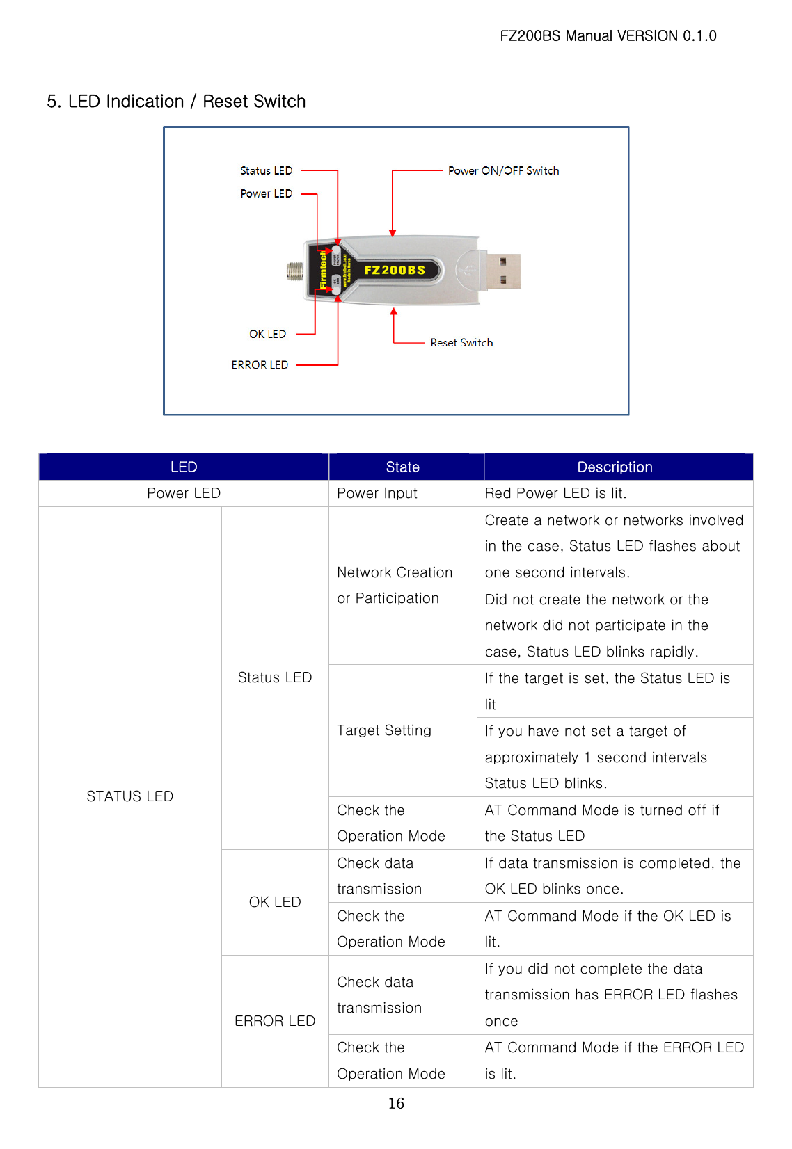
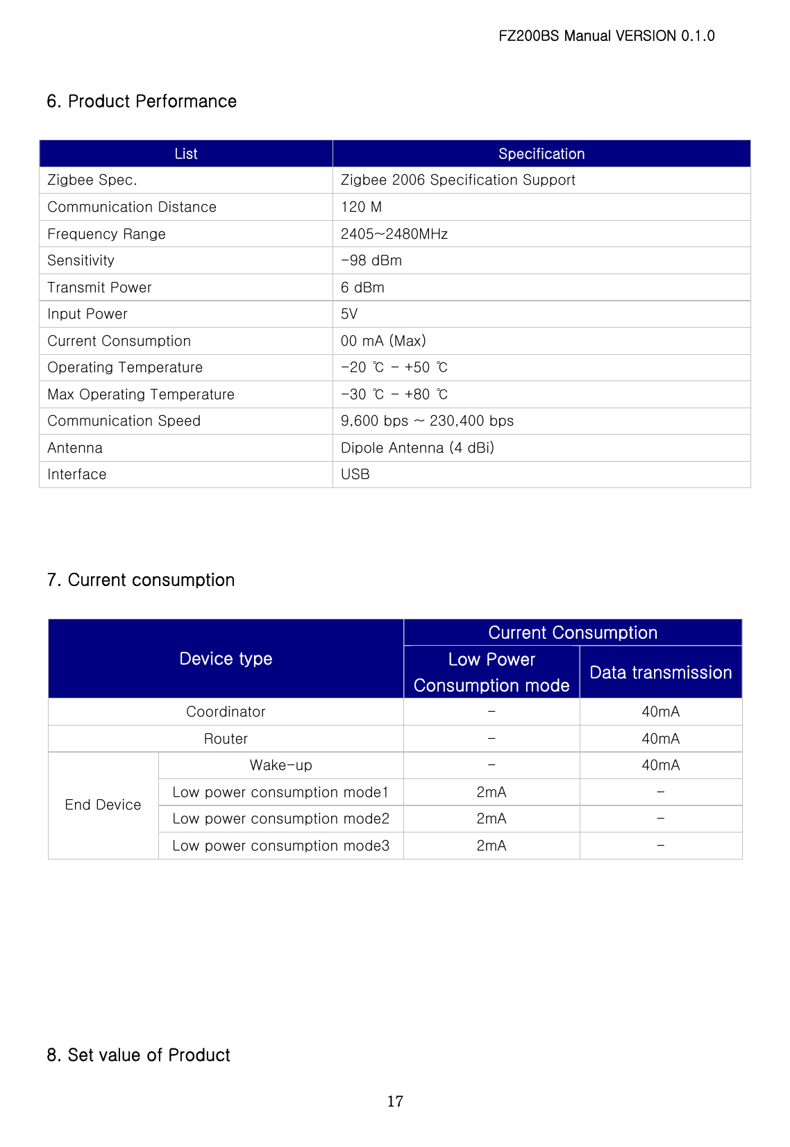
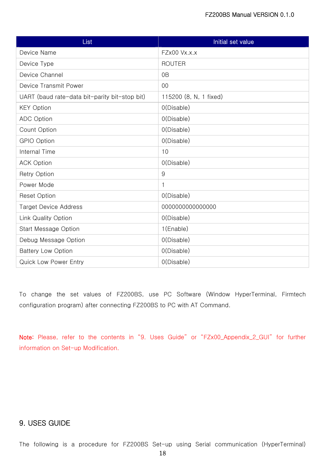
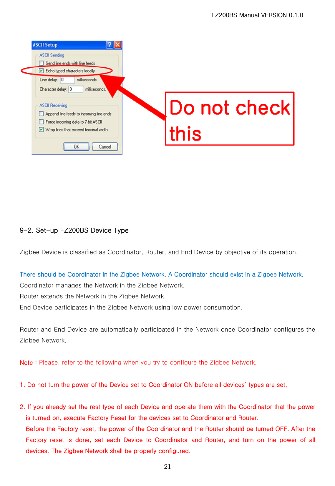
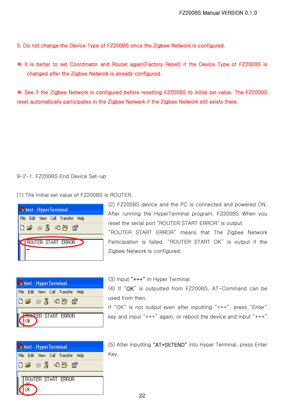
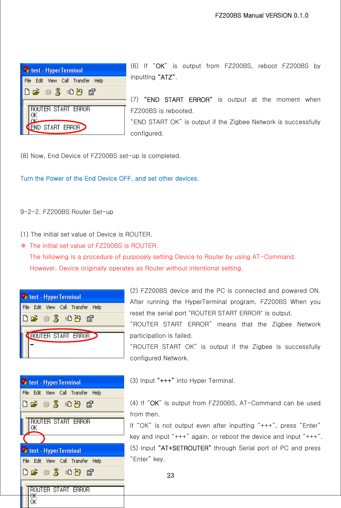
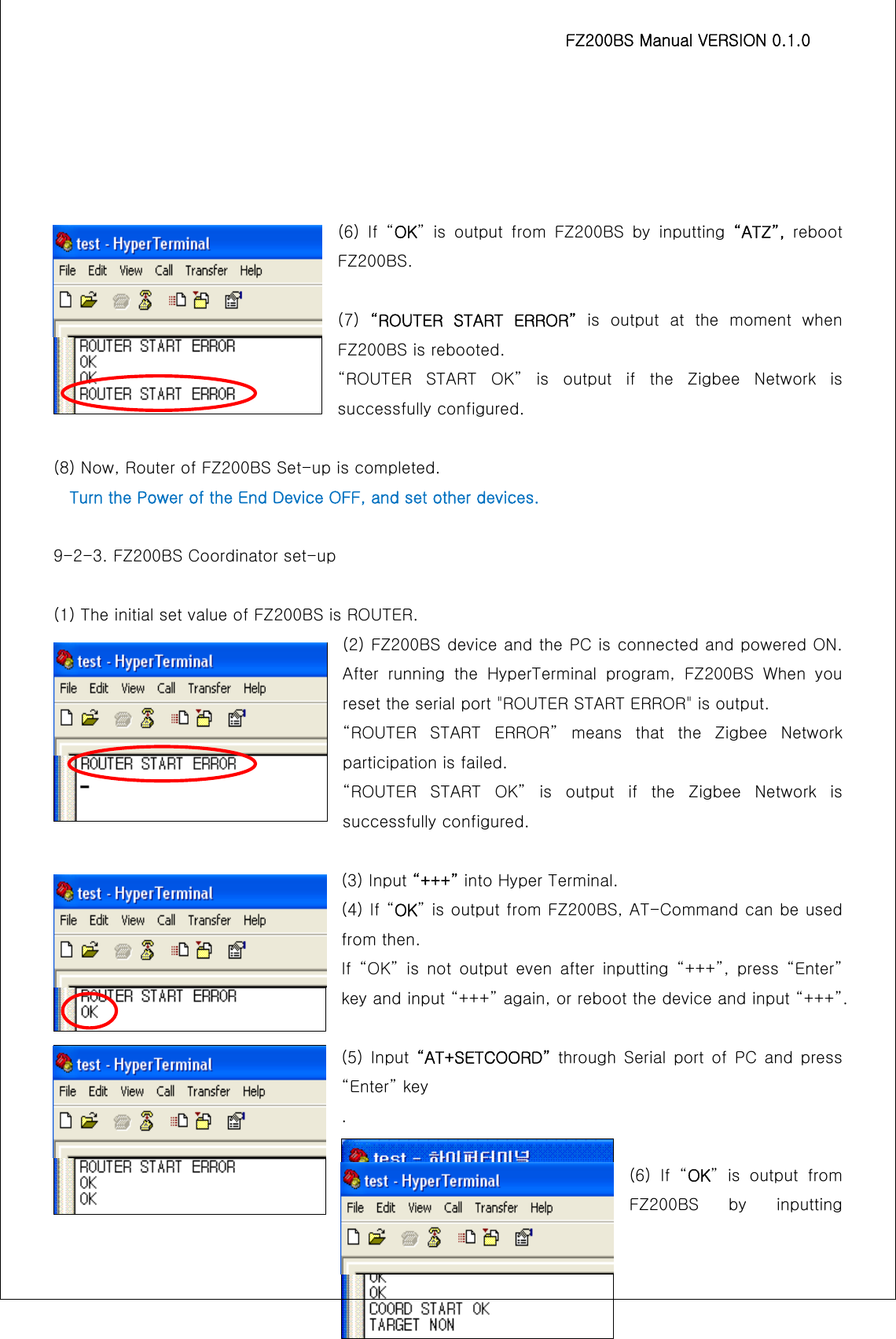
![FZ200BS Manual VERSION 0.1.0 12■ List of contents IMPORTANT NOTE: .......................................................................................................................................................2 FCC RF RADIATION EXPOSURE STATEMENT:......................................................................................................2 1. PRODUCT COMPONENTS ......................................................................................................................................13 2. PRODUCT APPEARANCE........................................................................................................................................14 3. USB INTERFACE.......................................................................................................................................................14 4. DIP SWITCH & INTERFACE SOCKET ...................................................................................................................15 5. LED INDICATION / RESET SWITCH......................................................................................................................16 6. PRODUCT PERFORMANCE....................................................................................................................................17 7. CURRENT CONSUMPTION .....................................................................................................................................17 8. SET VALUE OF PRODUCT......................................................................................................................................17 9. USES GUIDE..............................................................................................................................................................18 9-1. SERIAL COMMUNICATION (HYPER TERMINAL) PROGRAM EXECUTE......................................................................19 9-2. SET-UP FZ200BS DEVICE TYPE ........................................................................................................................21 9-2-1. FZ200BS End Device Set-up..............................................................................................................22 9-2-2. FZ200BS Router Set-up.......................................................................................................................23 9-2-3. FZ200BS Coordinator set-up..............................................................................................................24 9-3. THE ZIGBEE NETWORK CONFIGURATION..............................................................................................................25 9-3-1. The Zigbee Network configuration.....................................................................................................25 9-3-2. Zigbee Network Extension ...................................................................................................................25 9-3-3. Zigbee Network Participation .............................................................................................................. 26 9-4. TARGET DEVICE SET-UP.......................................................................................................................................26 9-4-1. Searching for an IEEE ADDRESS of Coordinator ...........................................................................27 9-4-2. Target device set-up ............................................................................................................................27 9-5. SERIAL DATA TRANSMISSION................................................................................................................................28 10. FZ200BS MANAGEMENT TIP ...............................................................................................................................30 10-1. FZ200BS DEVICE TYPE SET-UP ......................................................................................................................30 10-2. ZIGBEE NETWORK CONFIGURATION ...................................................................................................................30 10-3. [SET-UP] TARGET DEVICE & TRAFFIC ...............................................................................................................31 10-4. START MESSAGE...........................................................................................................................................32 10-5. RESET OPTION...............................................................................................................................................34](https://usermanual.wiki/Firmtech/FZ200BS/User-Guide-1496806-Page-12.png)
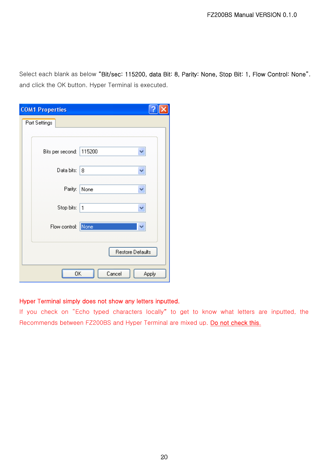
![FZ200BS Manual VERSION 0.1.0 19Program. The signal speed of FZ200BS is basically 115200bps. 9-1. Serial Communication (Hyper Terminal) Program Execute FZ200BS first power ON. Using a USB virtual COM Port FZ200BS By using the device's power is not ON unless you can not run the HyperTerminal. Select [Start][All Programs][Accessories][Communication][Hyper Terminal] in order, and then a window for Connection Set-up comes up. Put a name in the name blank, and click the OK button. When a window for Connection target comes up, select COM ports connected to FZ200BS, and click the OK button.](https://usermanual.wiki/Firmtech/FZ200BS/User-Guide-1496806-Page-19.png)
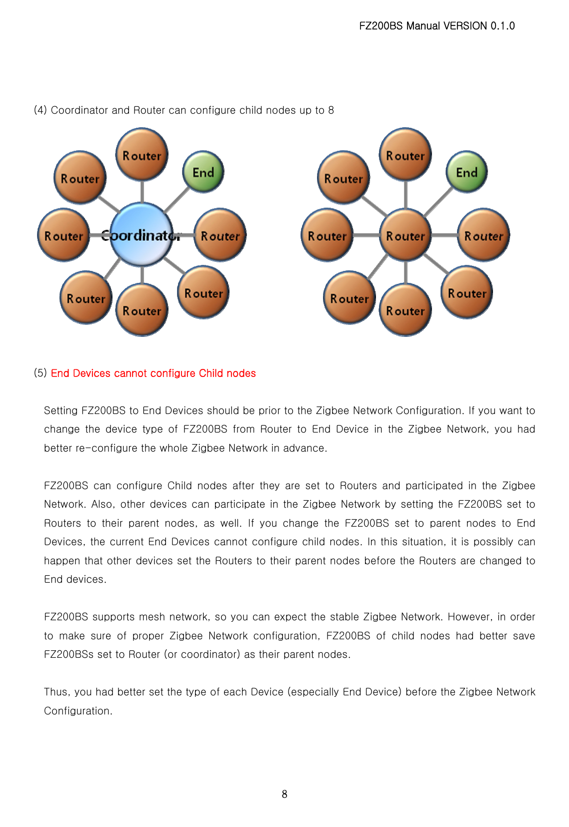
![FZ200BS Manual VERSION 0.1.0 31(1) Turn the power of FZ200BS set to Coordinator ON. (2) Turn the power of Router and End Device which are supposed to make 1 Depth ON. - You can create Devices in 1 Depth up to 8. (3) Turn the power of Router and End Device which are supposed to make 2 Depth ON. - You can create Devices in 2 Depth up to the number of Router in 1 Depth * 8. - Devices are automatically created in 1 Depth if any seats are available in 1 Depth. (4) Turn the power of Router and End Device which are supposed to make 3 Depth ON. - You can create Devices in 3 Depth up to the number of Router in 2 Depth * 8. - Devices are automatically created in 1/2 Depth if any seats are available in 1/2 Depth. (5) Turn the power of Router and End Device which are supposed to make 4 Depth ON. - You can create Devices in 4 Depth up to the number of Router in 3 Depth * 8. - Devices are automatically created in 1/2/3 Depth if any seats are available in 1/2/3 Depth. 10-3. [Set-up] target device & traffic Set target device of each Device after the Zigbee Network is configured. Save an IEEE ADDRESS of target device by using a command “AT+SETTARGET” Reset the Device so that its target device set-up can be processed. < It is not recommended that there is a lot of traffic in the Zigbee Network. > Refer to the meanings of Traffic in terms of Zigbee Network. The Traffic is caused by “Zigbee Device which performs data transmission in the Zigbee Network”, “Zigbee Device which performs data transmission to get its target device”, “Zigbee Device which transmits data to its target device” “ACK data for checking if Zigbee Device transmits data its target device properly”, and “Transmitted data for checking if the Zigbee Network works properly.” There is no traffic in case of Coordinator and Router unless they are turned ON again. Coordinator and Router are always turned ON because they intermediate Devices. In case of End Device, a lot of traffic is caused because the power of End Device is turned ON and OFF repeatedly.](https://usermanual.wiki/Firmtech/FZ200BS/User-Guide-1496806-Page-31.png)