First Computer CE260A Notebook PC User Manual for CE260 CE261
First International Computer Inc Notebook PC for CE260 CE261
UserManual.wiki
>
First Computer
>
CE260A User Manual
>
manual
Contents
1.
manual
2.
Original User manual
manual
Navigation menu
Upload a User Manual
Namespaces
Wiki Guide
HTML
PDF
Info
Views
User Manual
Discussion / Help
Navigation
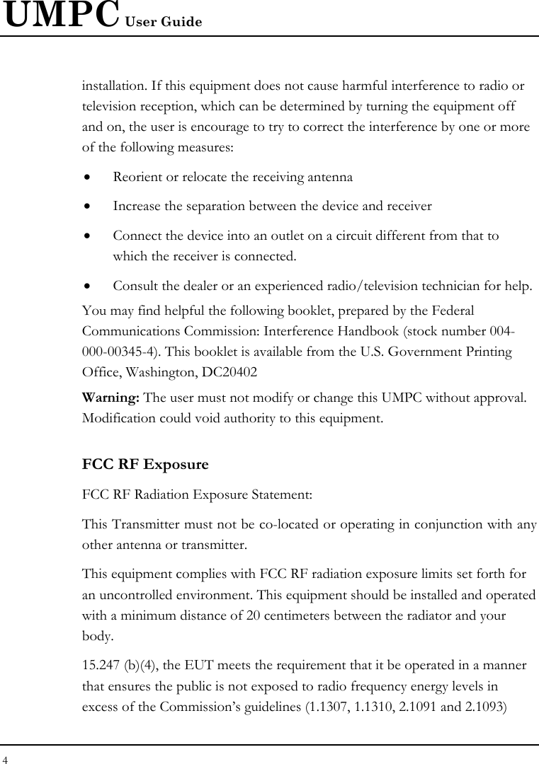
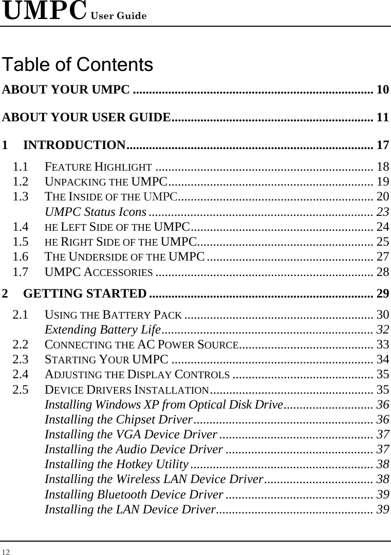
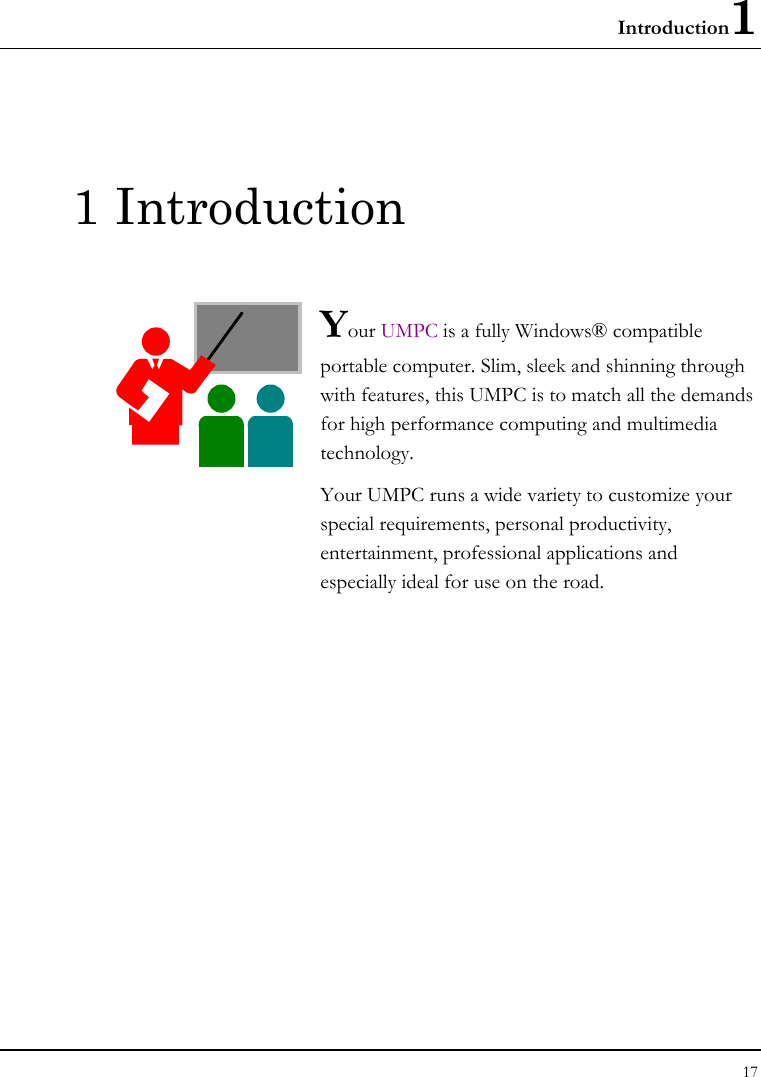
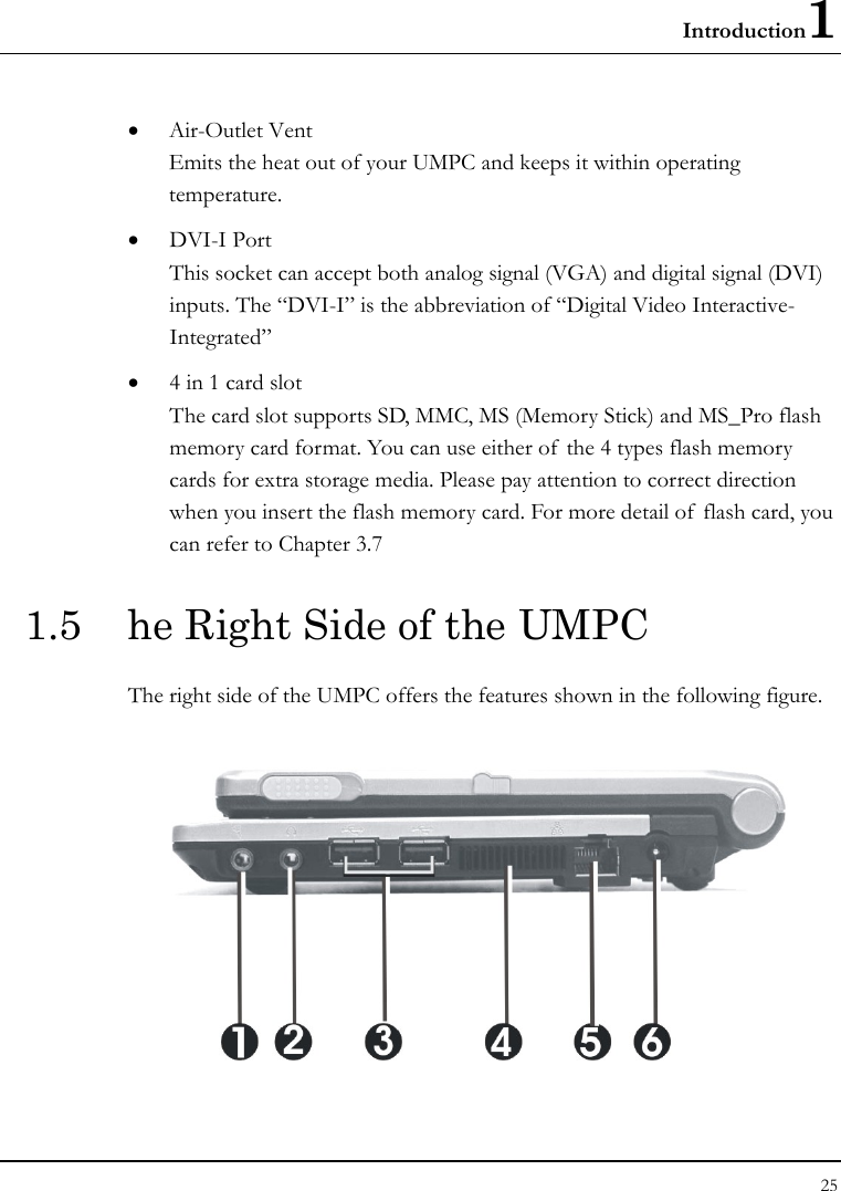
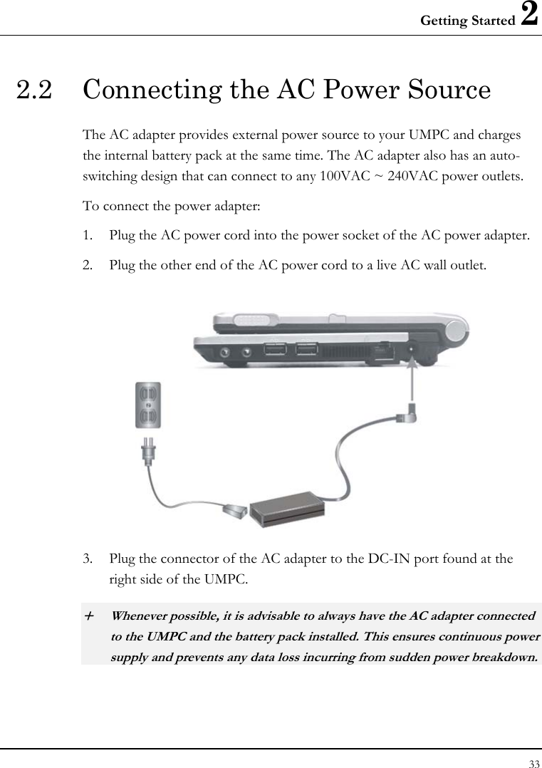
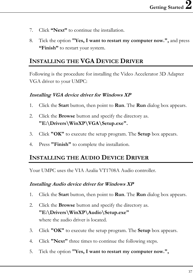

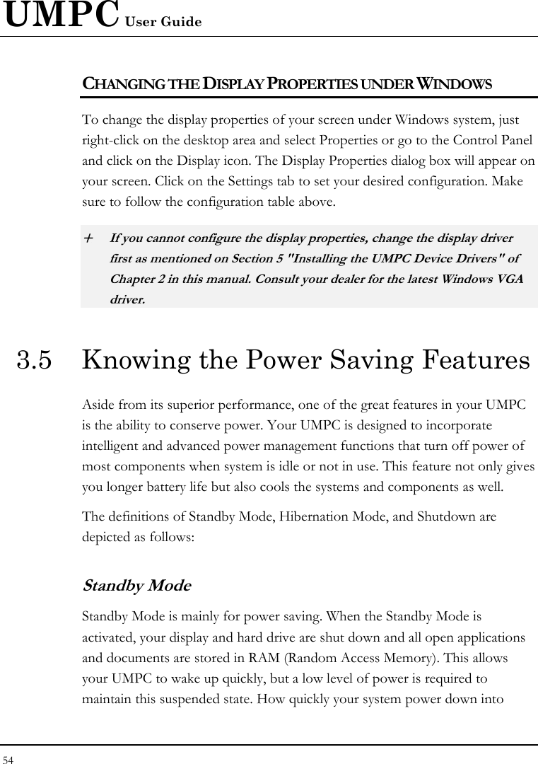

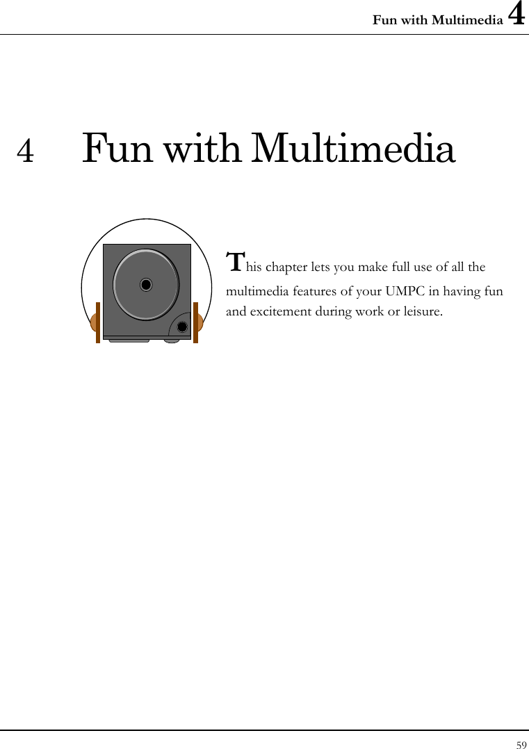
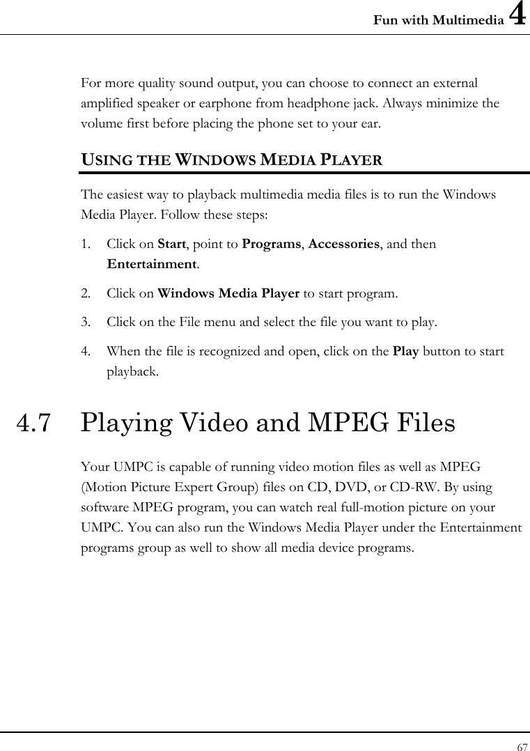
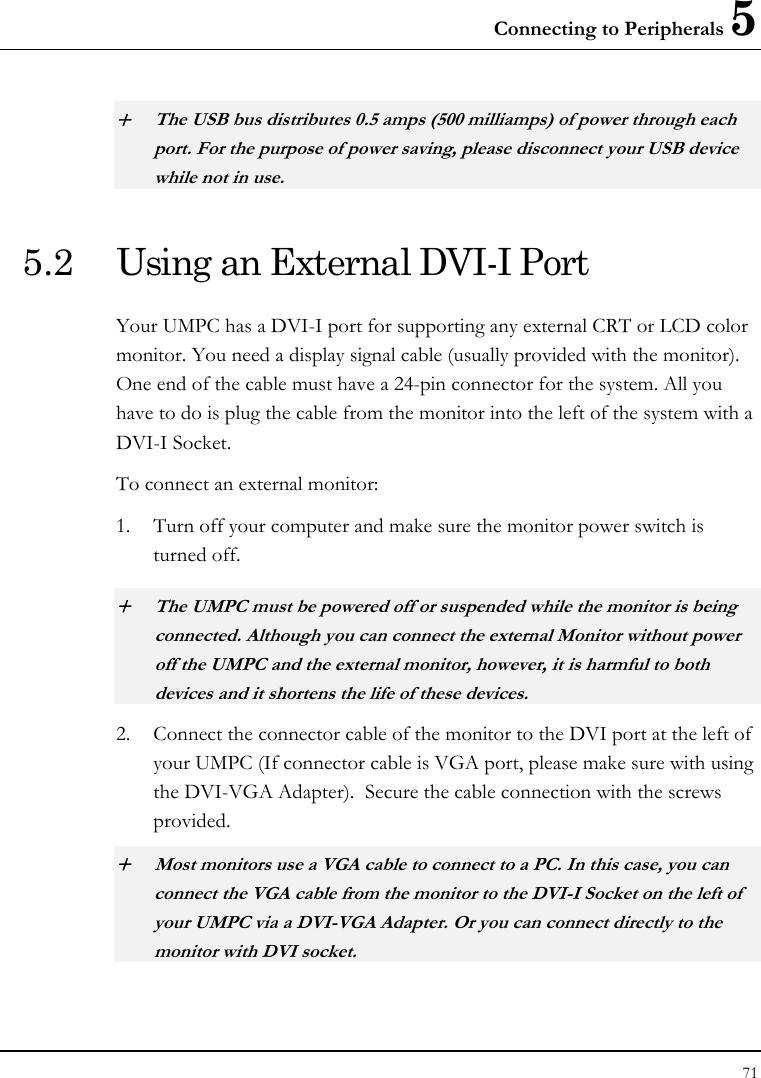
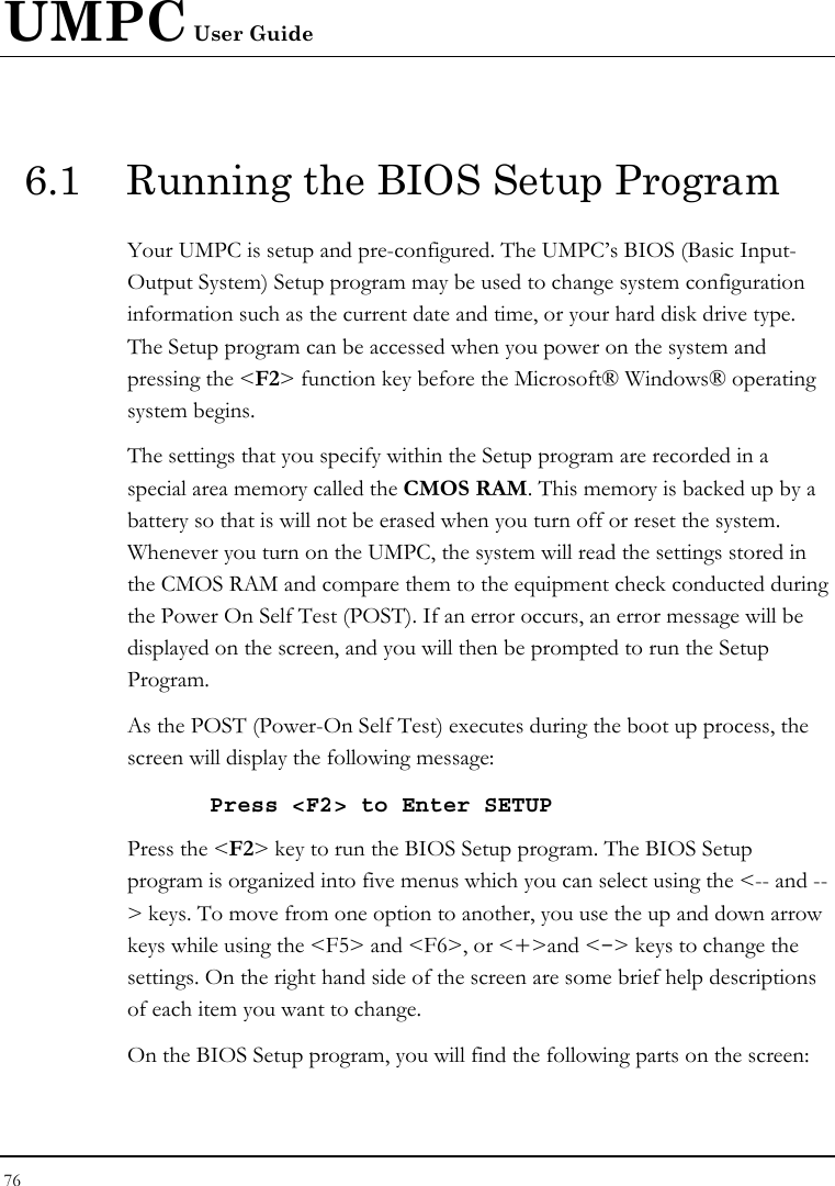
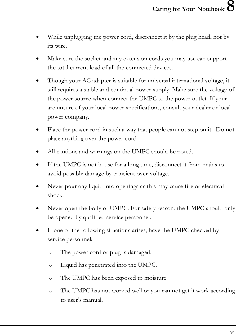
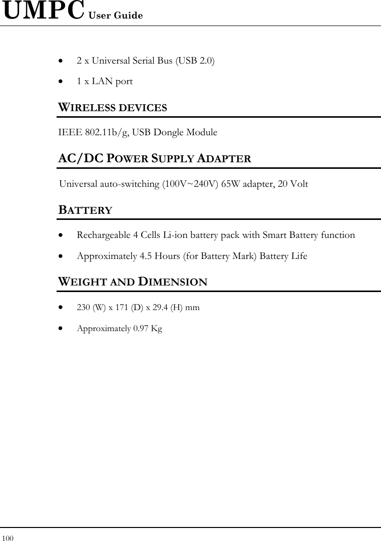
![UMPC User Guide 78 6.2 Using the Main Menu Setup Phoenix BIOS Setup Utility Main Advanced Security Boot Exit Item Specific Help System Time: [07 :54 :32] <Tab>, <Shift-Tab>, System Date: [06/11/2007] or <Enter> selects Language [English (US)] field. 4Secondary Master [40008MB] CPU Type: VIA Esther processor 1200MHz CPU Speed: 1200 MHz System Memory: 640 KB Extended Memory: 457728 KB BIOS Version: 0.4A-2309-8A20 F1 Help Ç È Select Item -/+ Change Values F9 Setup Defaults Esc Exit Å--> Select Menu Enter Select Sub-Menu F10 Save and Exit • System Time Allows you to change the system time using the hour:minute:second format of the UMPC. Enter the current time for reach field and use the <Tab>, <Shift>+<Tab>, or <Enter> key to move from one field or back to another. You can also change the system time from your operating system.](https://usermanual.wiki/First-Computer/CE260A.manual/User-Guide-835632-Page-78.png)
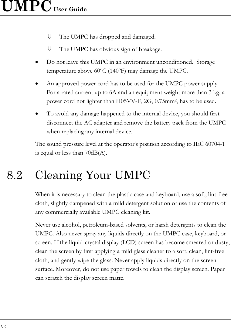
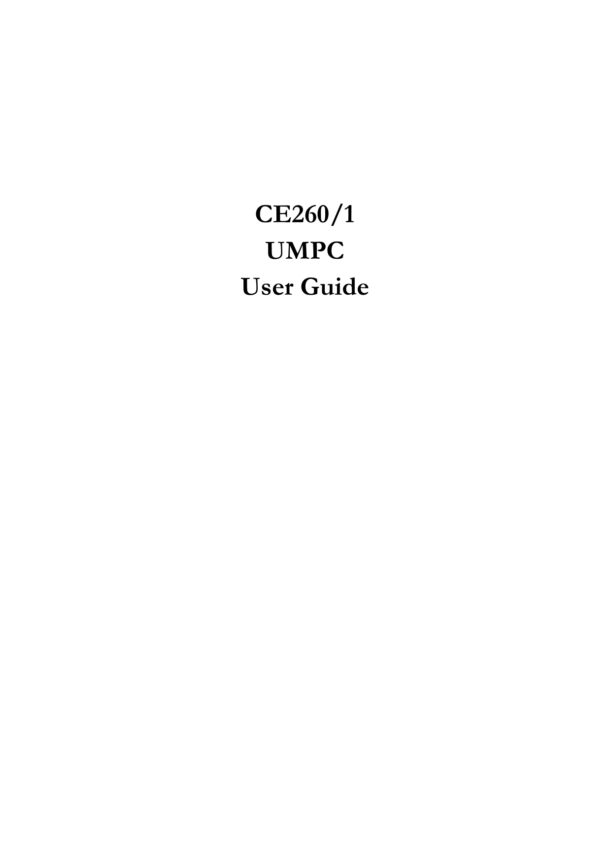
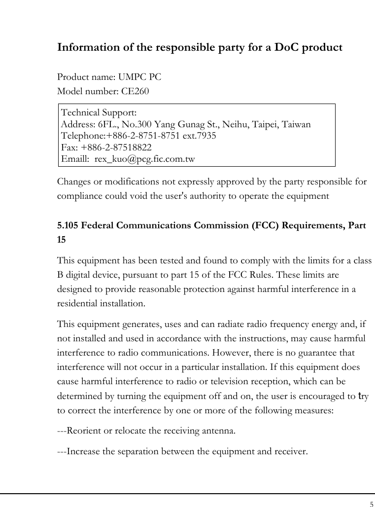
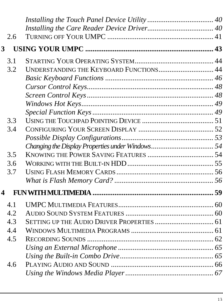
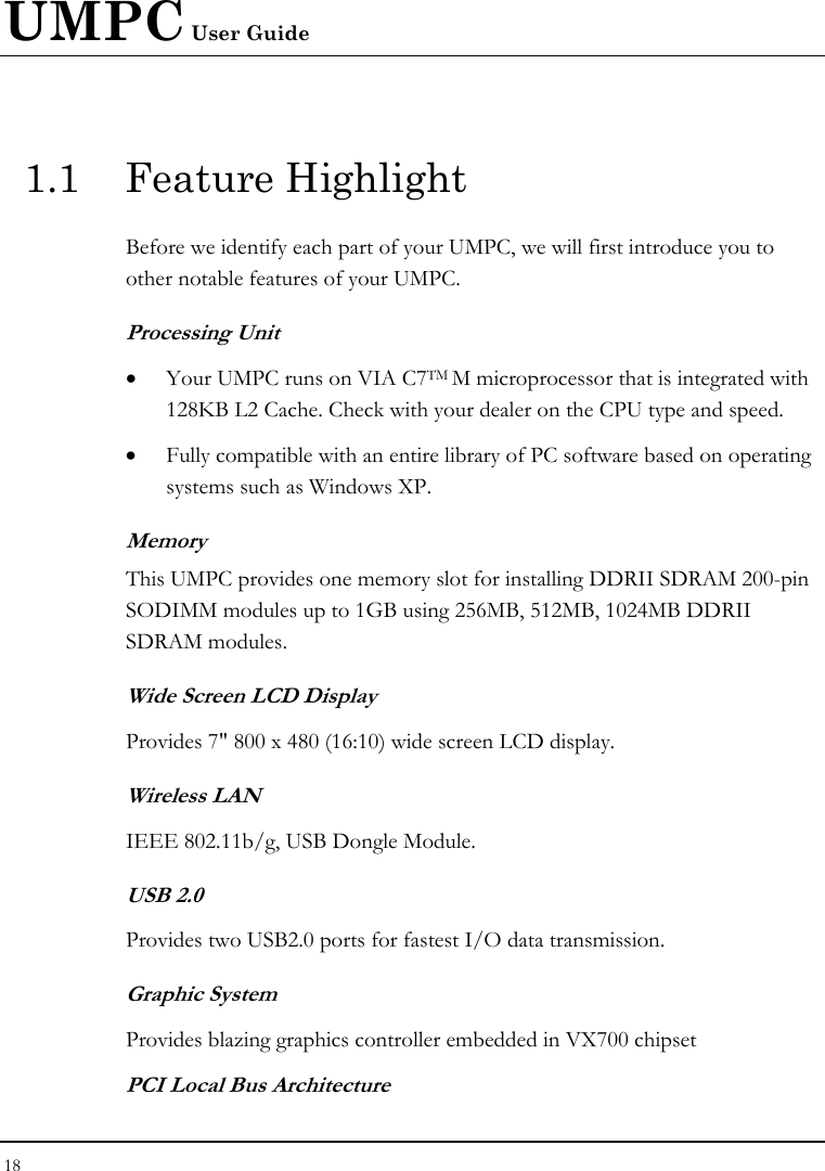
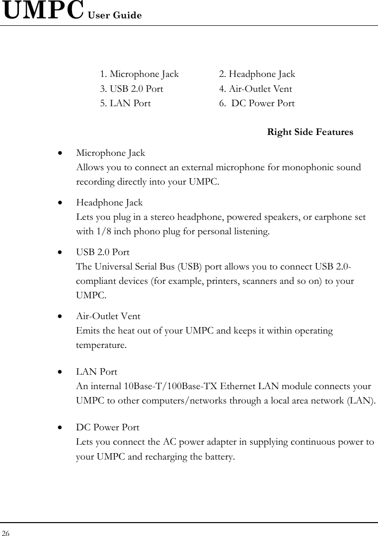
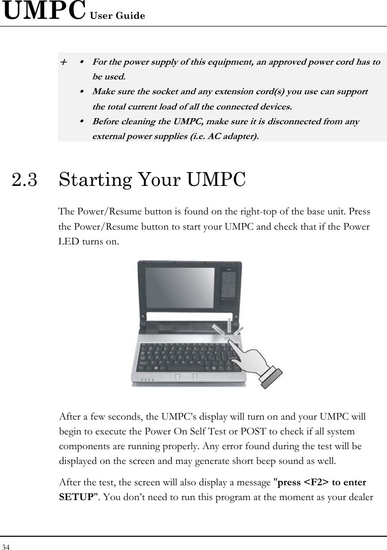
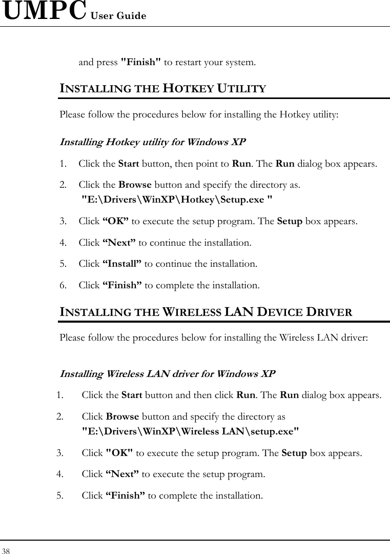
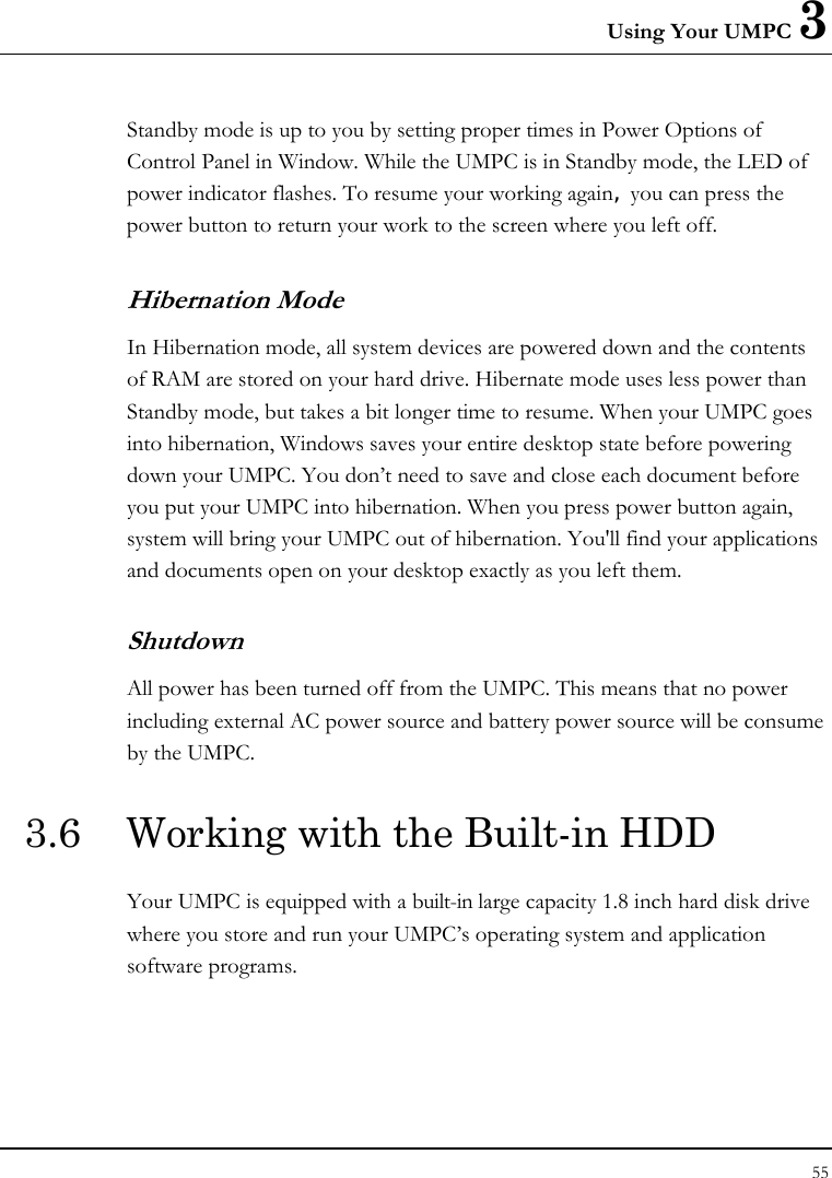
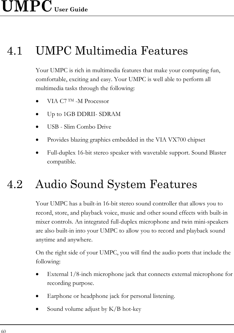
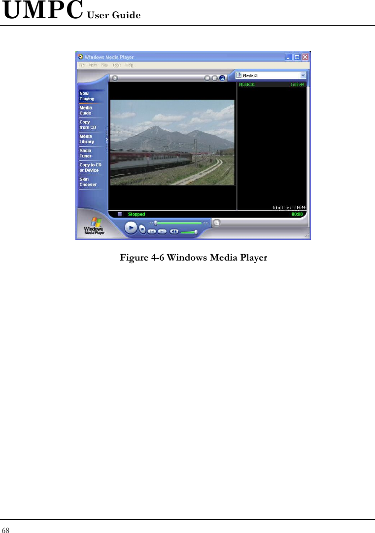
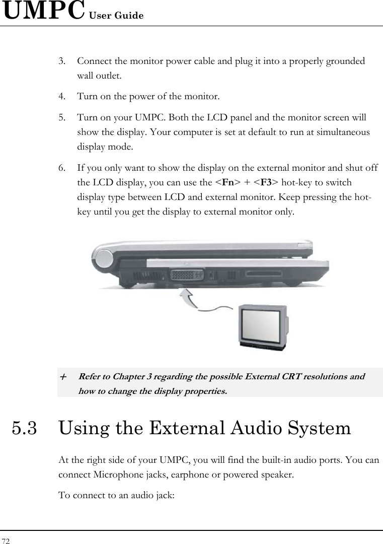
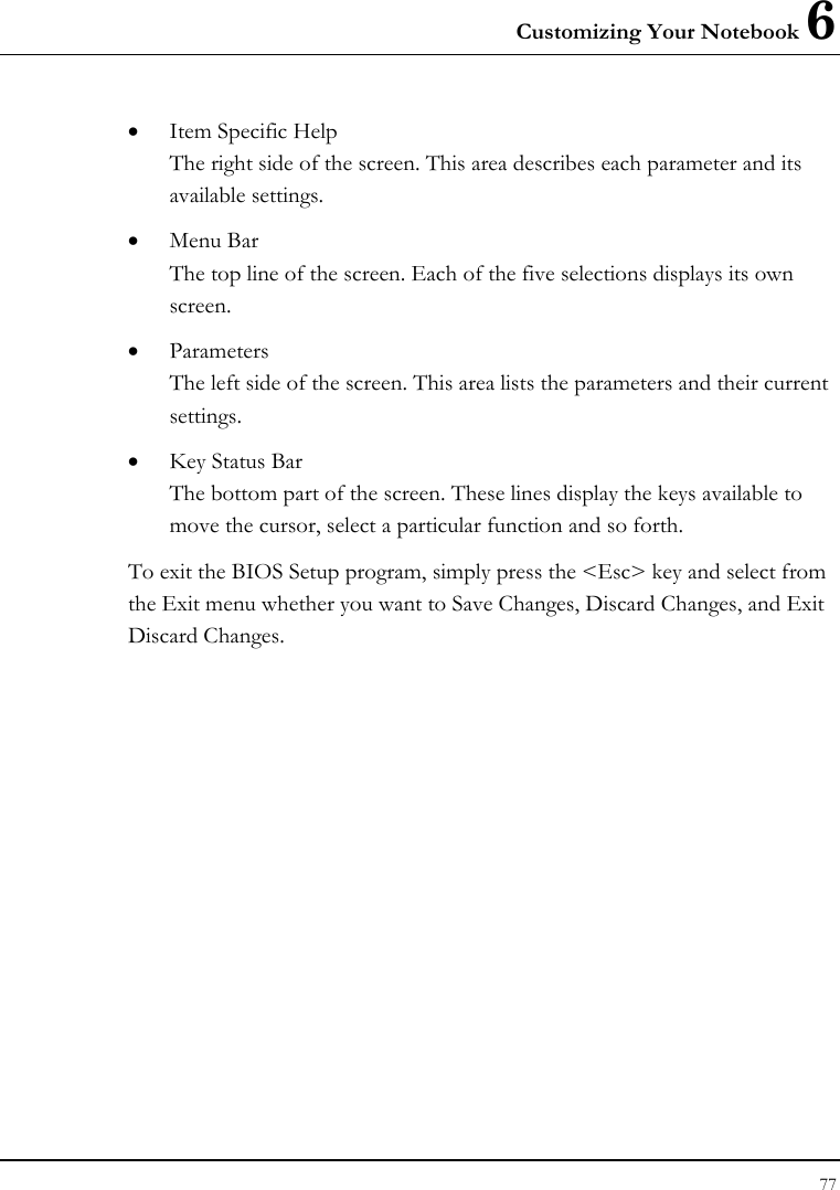
![UMPC User Guide 80 6.2.1 INTERNAL HDD SUB-MENU Phoenix BIOS Setup Utility Main IDE Channel 1 Master [FUJITSU MHV2080BH PL-(S1)] Item Specific Help Type: [Auto]This setting enables or LBA Format disables 32 bit IDE data Total Sector: 78126048 transfers. Maximum Capacity: 40008 MB Multi-Sector Transfers: [16 Sectors] LBA Mode Control: [Enabled] 32 Bit I/O: [Disabled] Transfer Mode: [FPIO 4 / DMA 2] Ultra DMA Mode: [Mode 2] SMART Monitoring: Enabled F1 Help Ç È Select Item -/+ Change Values F9 Setup Defaults Esc Exit Å--> Select Menu Enter Select Sub-Menu F10 Save and Exit Use the Type field to select the drive type installed. You can select different drive types as CD-ROM, User, Auto or None by pressing <Space> bar. Set this option to Auto so your UMPC will automatically detect the drive type during power on. Set this option to None when your UMPC is not installed any devices. Press <Esc> to return to the Main Menu.](https://usermanual.wiki/First-Computer/CE260A.manual/User-Guide-835632-Page-80.png)
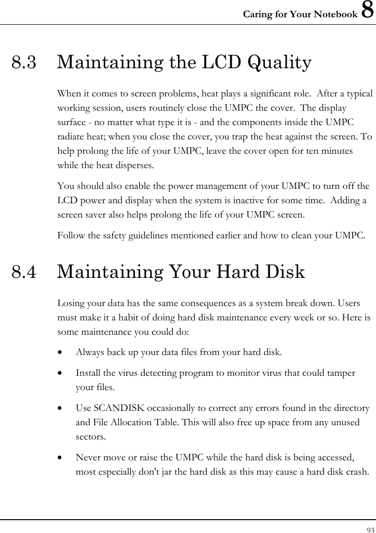
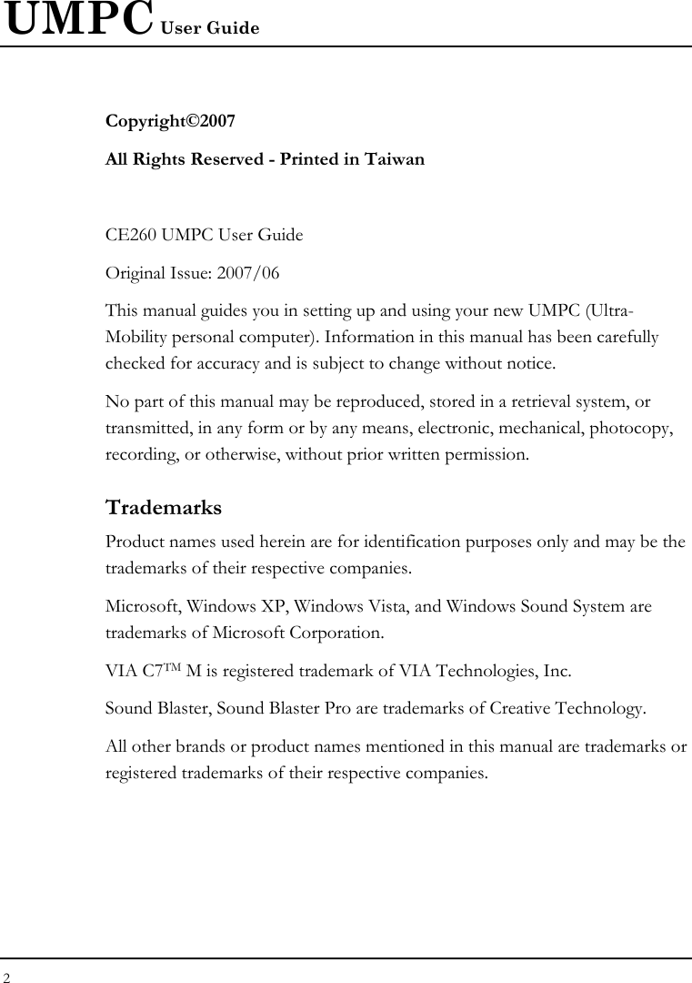
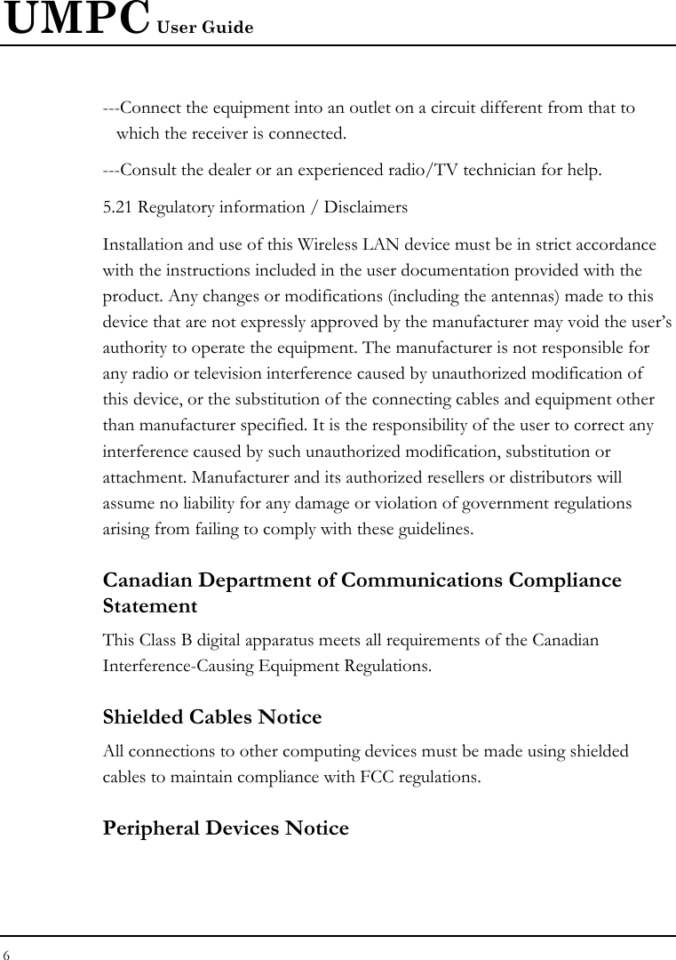
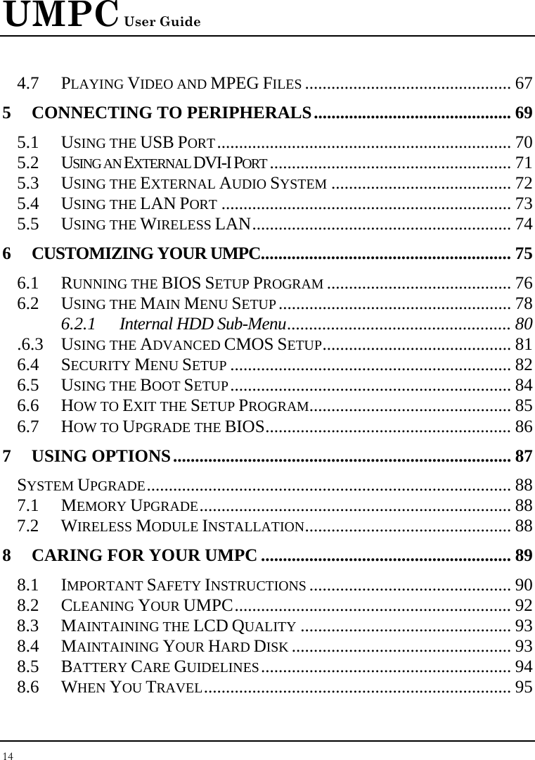
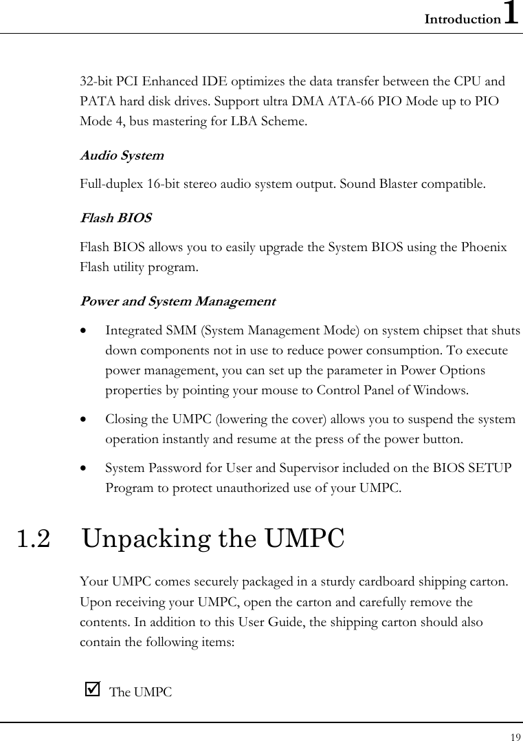
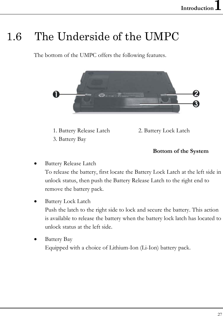
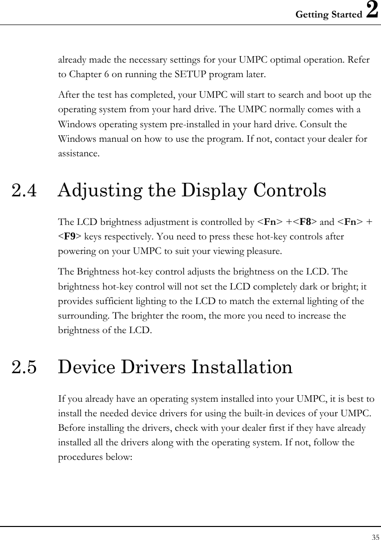
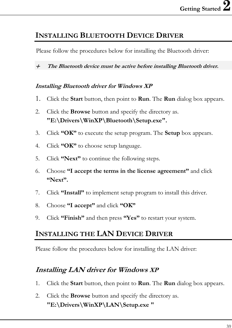
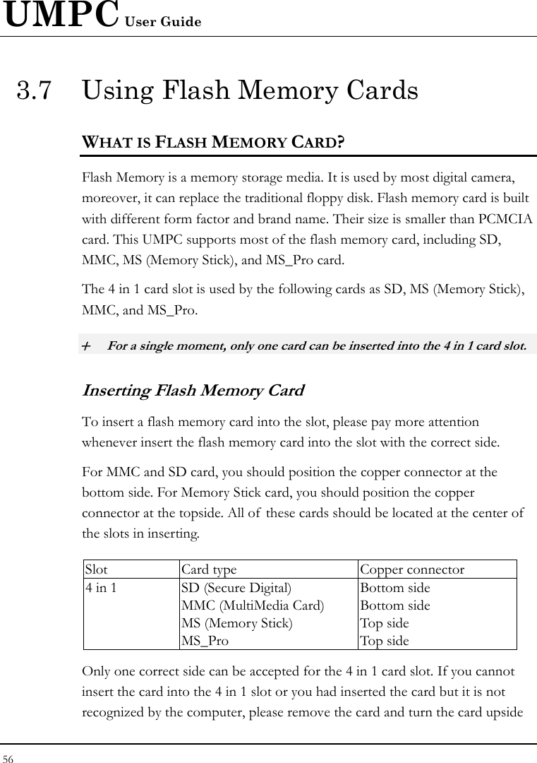
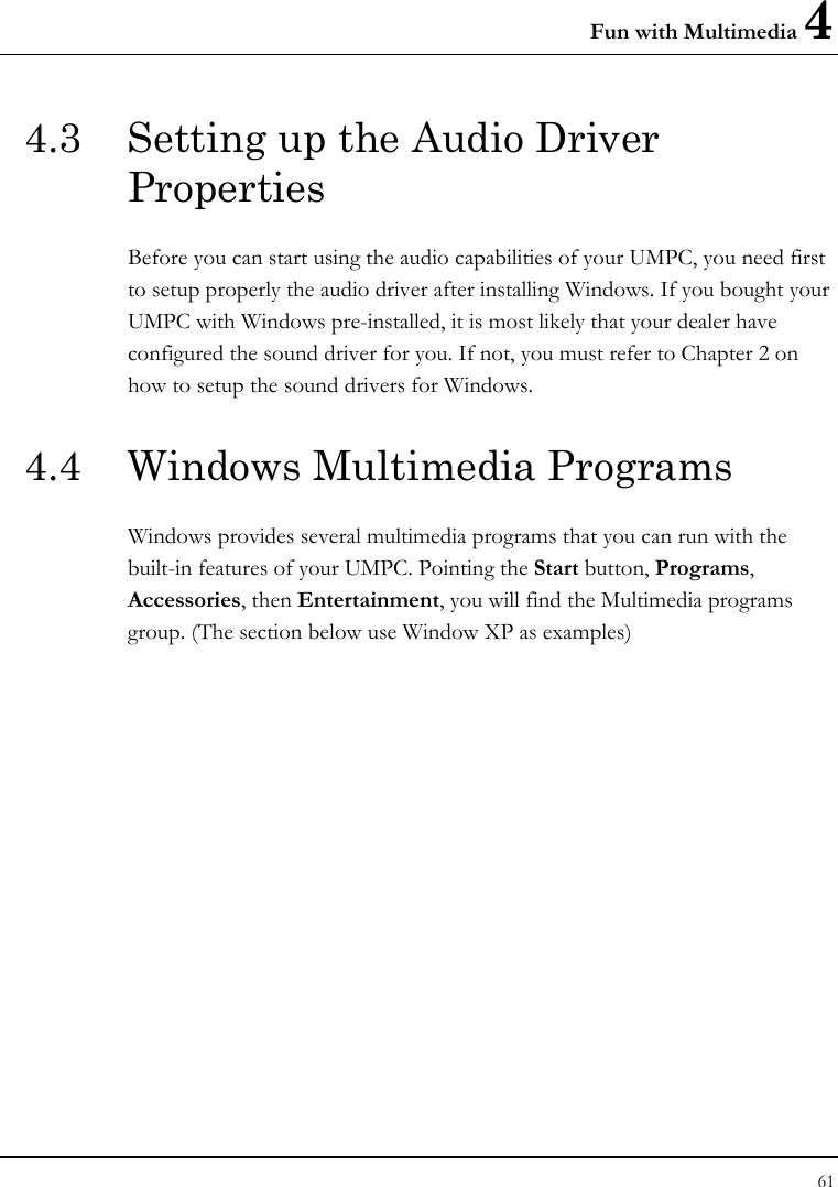
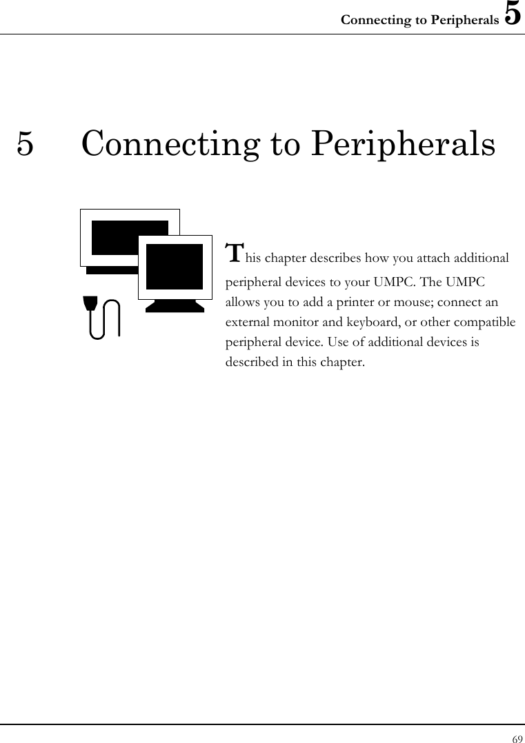
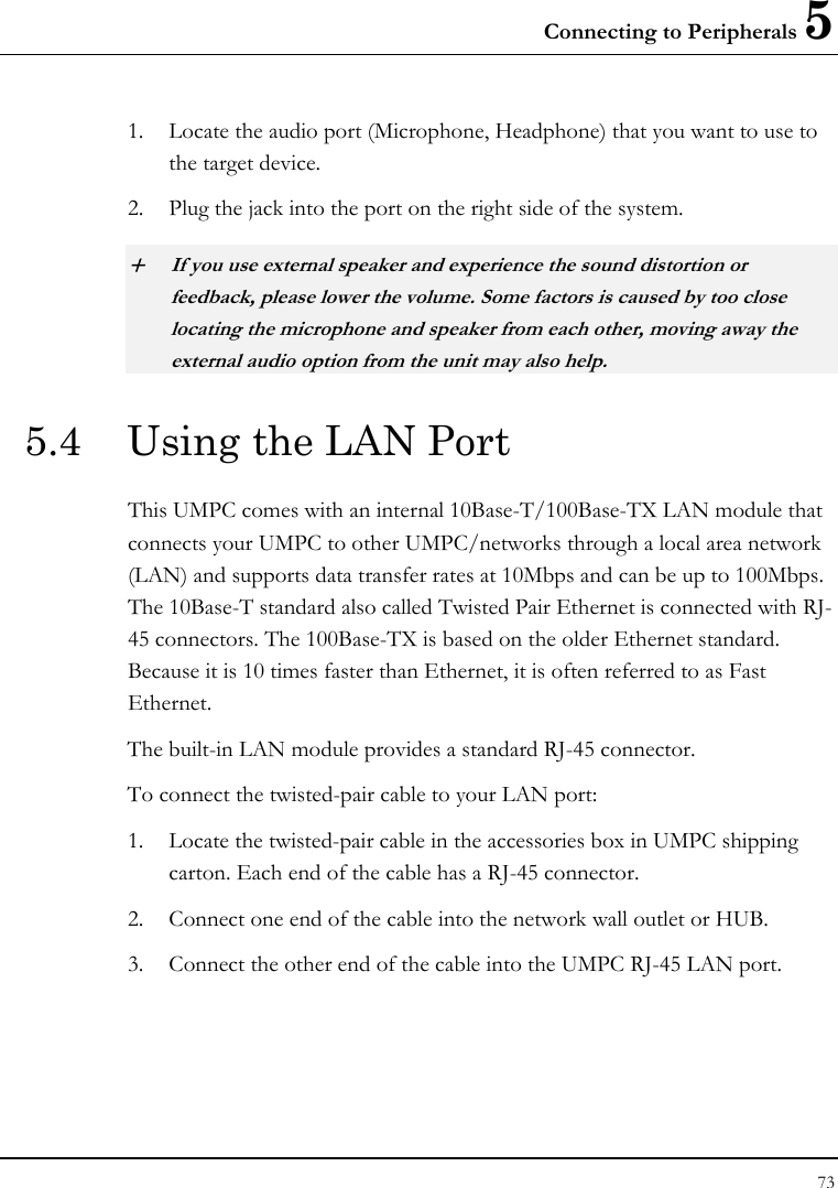
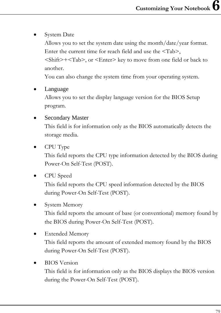
![Customizing Your Notebook 6 81 .6.3 Using the Advanced CMOS Setup Phoenix BIOS Setup Utility Main Advanced Security Boot Exit Item Specific Help PS/2 Mouse [Enabled] Display system Display Device Selection 1: [CRT] Configuration on boot Legacy USB Support [Enabled] . . F1 Help Ç È Select Item -/+ Change Values F9 Setup Defaults Esc Exit Å--> Select Menu Enter Select Sub-Menu F10 Save and Exit • PS/2 Mouse Lets you activate or inactivate the mouse function. [Disabled] prevents any installed PS/2 mouse from functioning. [Enabled] forces the PS/2 mouse port to be enabled regardless if a mouse is present or not. • Display Device Selection 1 Lets you specify the external display device to CRT or DVI. • Legacy USB Support Enable or disable the USB Bus support when in connection with USB device.](https://usermanual.wiki/First-Computer/CE260A.manual/User-Guide-835632-Page-81.png)
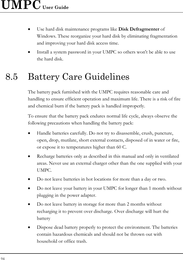
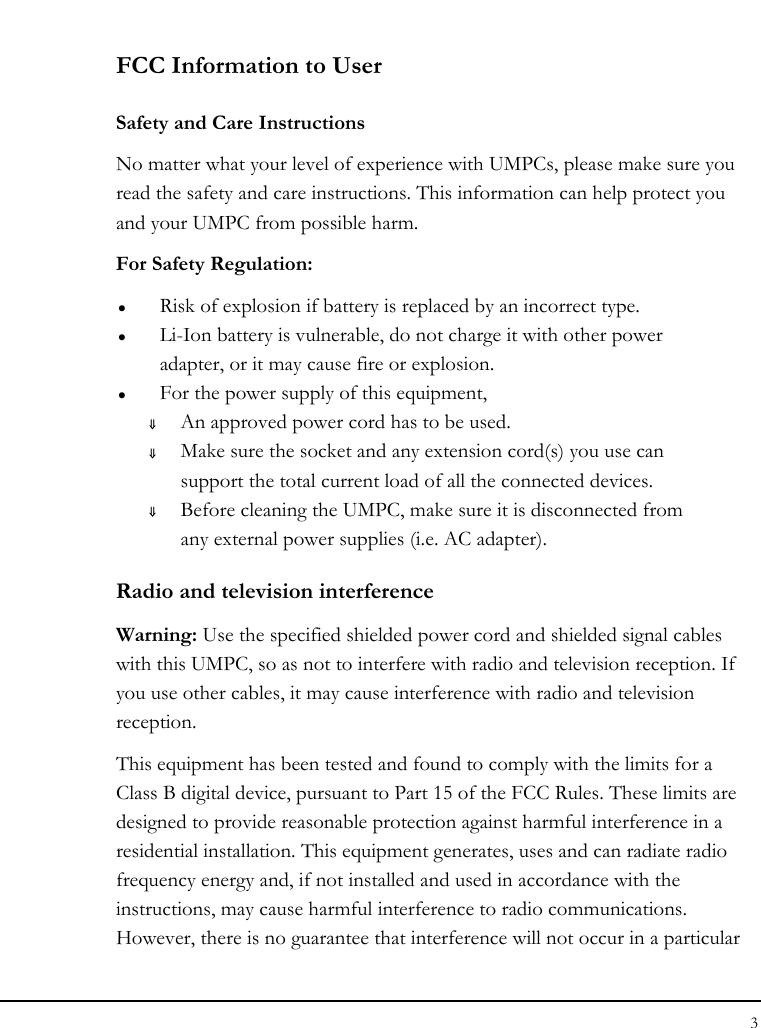
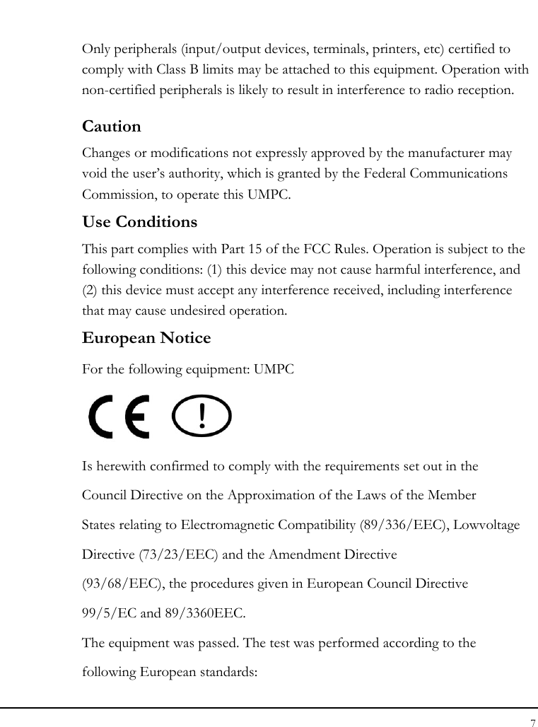
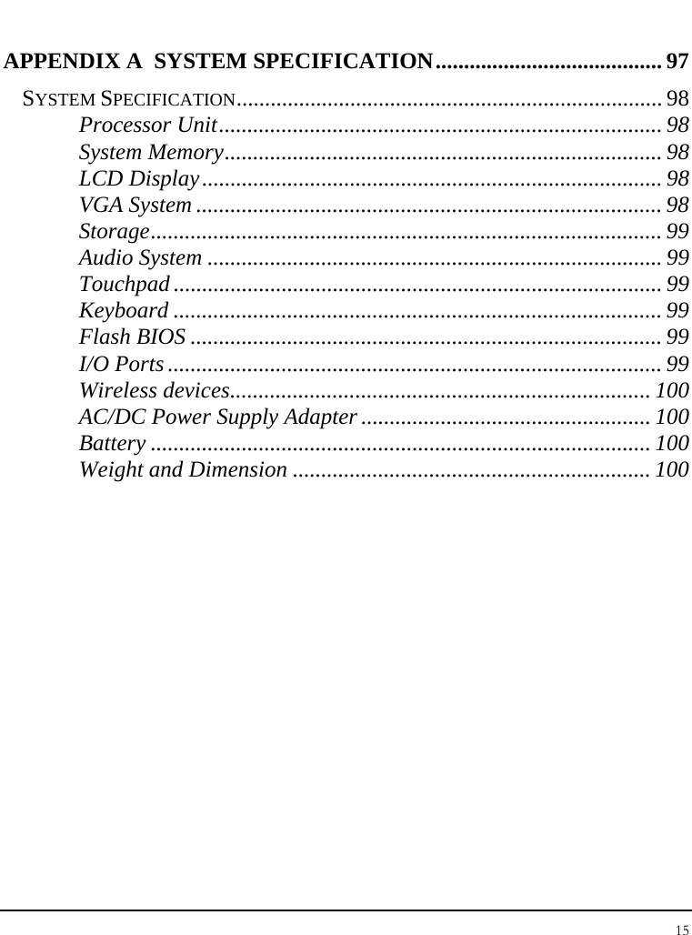
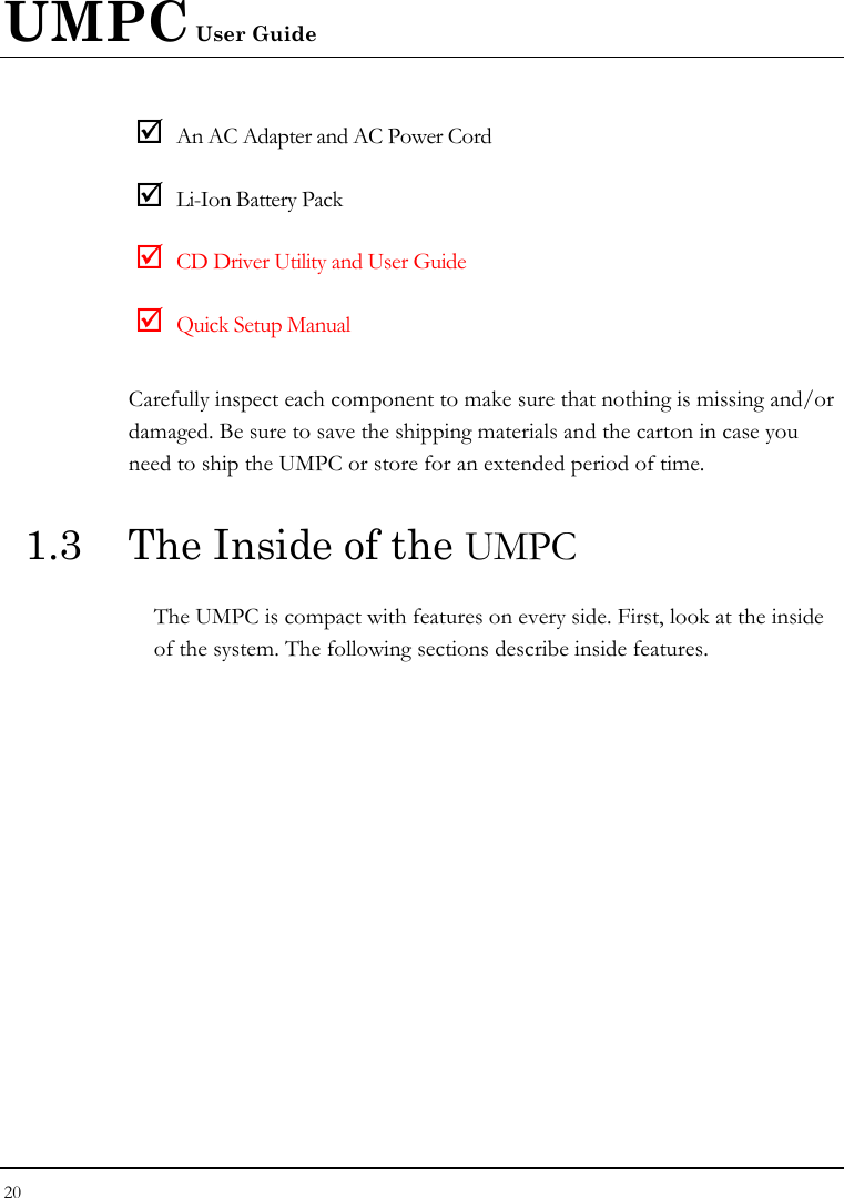
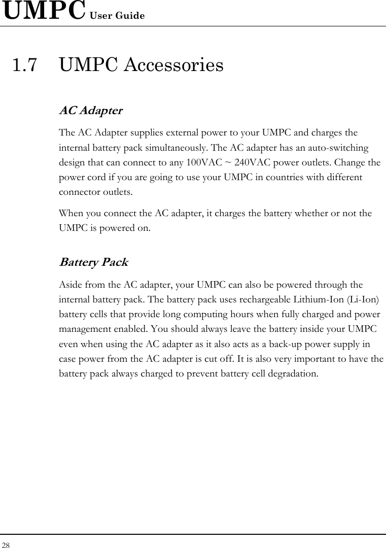
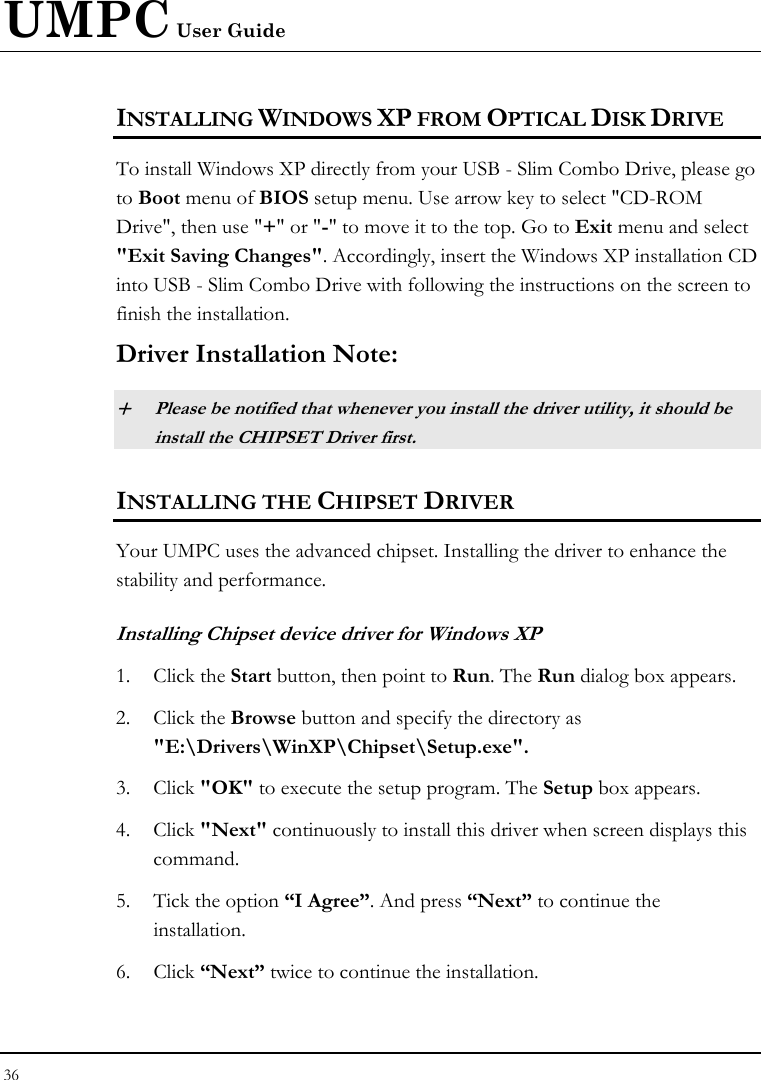
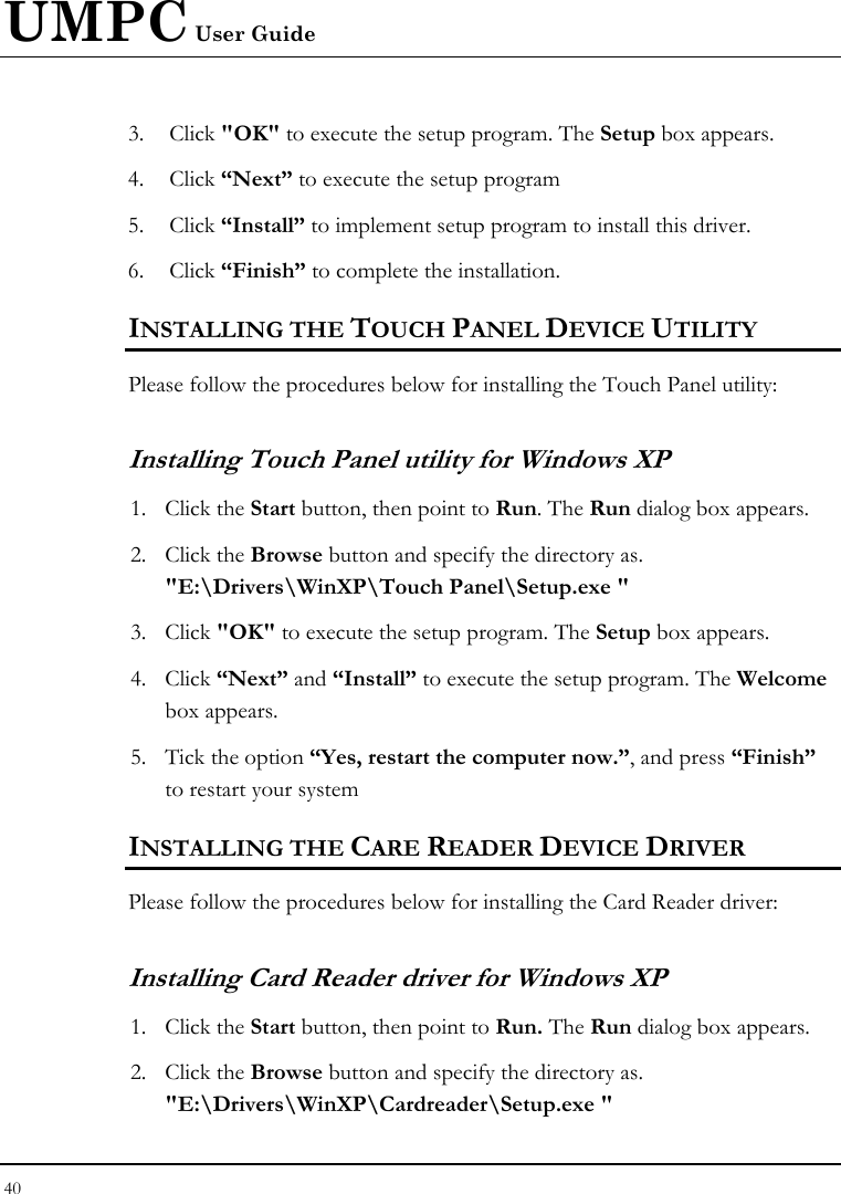
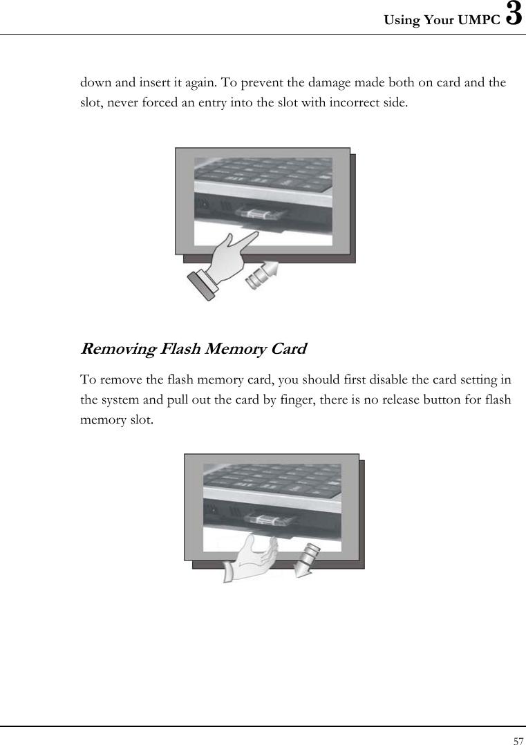
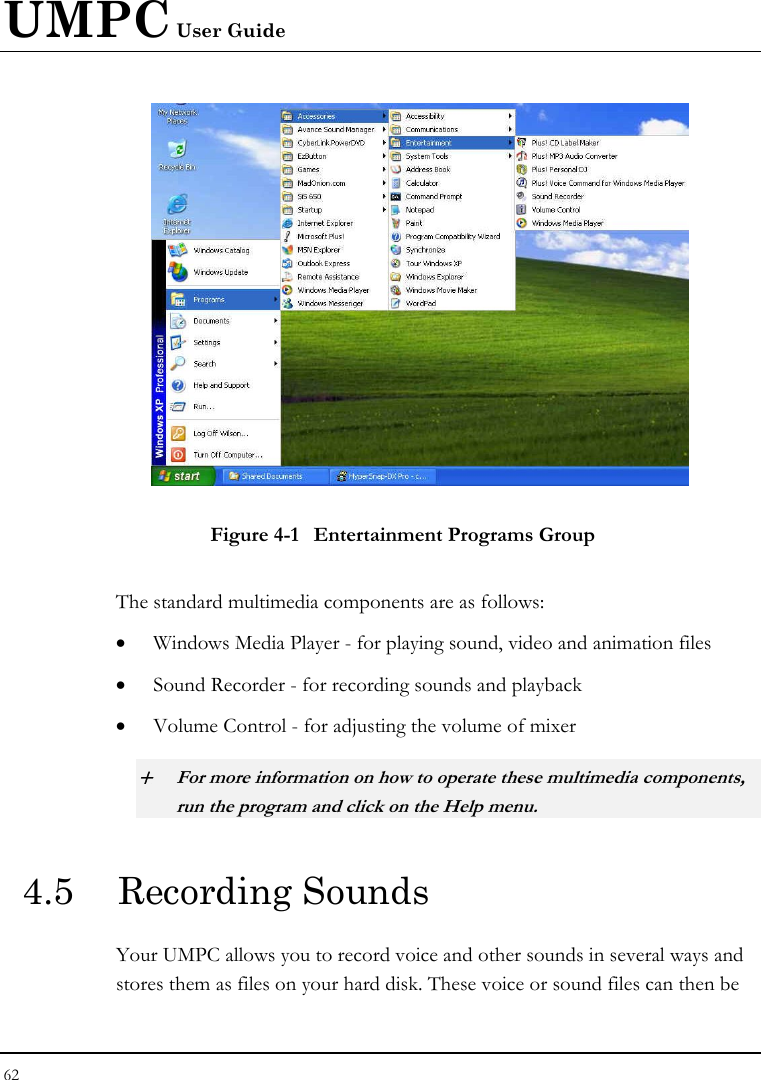
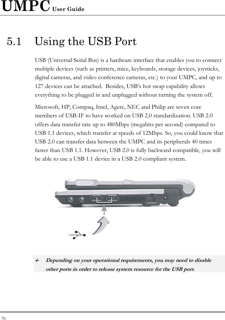
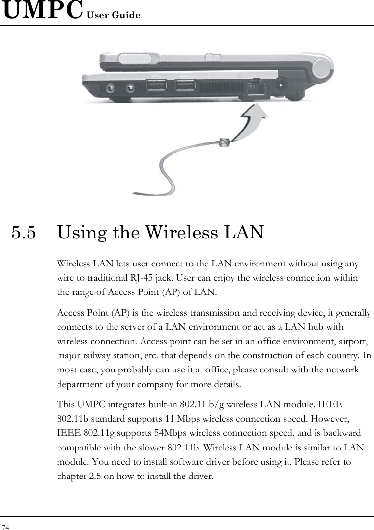
![UMPC User Guide 82 6.4 Security Menu Setup Phoenix BIOS Setup Utility Main Advanced Security Boot Exit Item Specific Help Supervisor Password Is: Clear User Password Is: Clear Supervisor Password controls access to the Set Supervisor Password [Enter] setup utility. Set User Password [Enter] Password on boot [Disabled] Fixed disk boot sector: [Normal] F1 Help Ç È Select Item -/+ Change Values F9 Setup Defaults Esc Exit Å--> Select Menu Enter Select Sub-Menu F10 Save and Exit • Supervisor Password Is Set/Clear selections show that the UMPC is under controlled by Supervisor Password or not. • User Password Is Set/Clear selections show that the UMPC is under controlled by User Password or not.](https://usermanual.wiki/First-Computer/CE260A.manual/User-Guide-835632-Page-82.png)