First Computer CE2A1A UMPC (Notebook) User Manual User Guide
First International Computer Inc UMPC (Notebook) User Guide
UserManual.wiki
>
First Computer
>
CE2A1A User Manual
User Manual
Navigation menu
Upload a User Manual
Namespaces
Wiki Guide
HTML
PDF
Info
Views
User Manual
Discussion / Help
Navigation


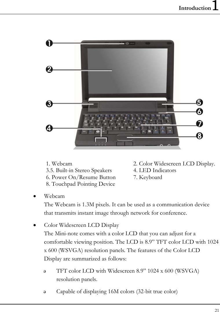
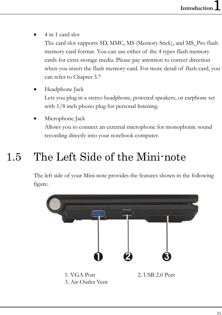


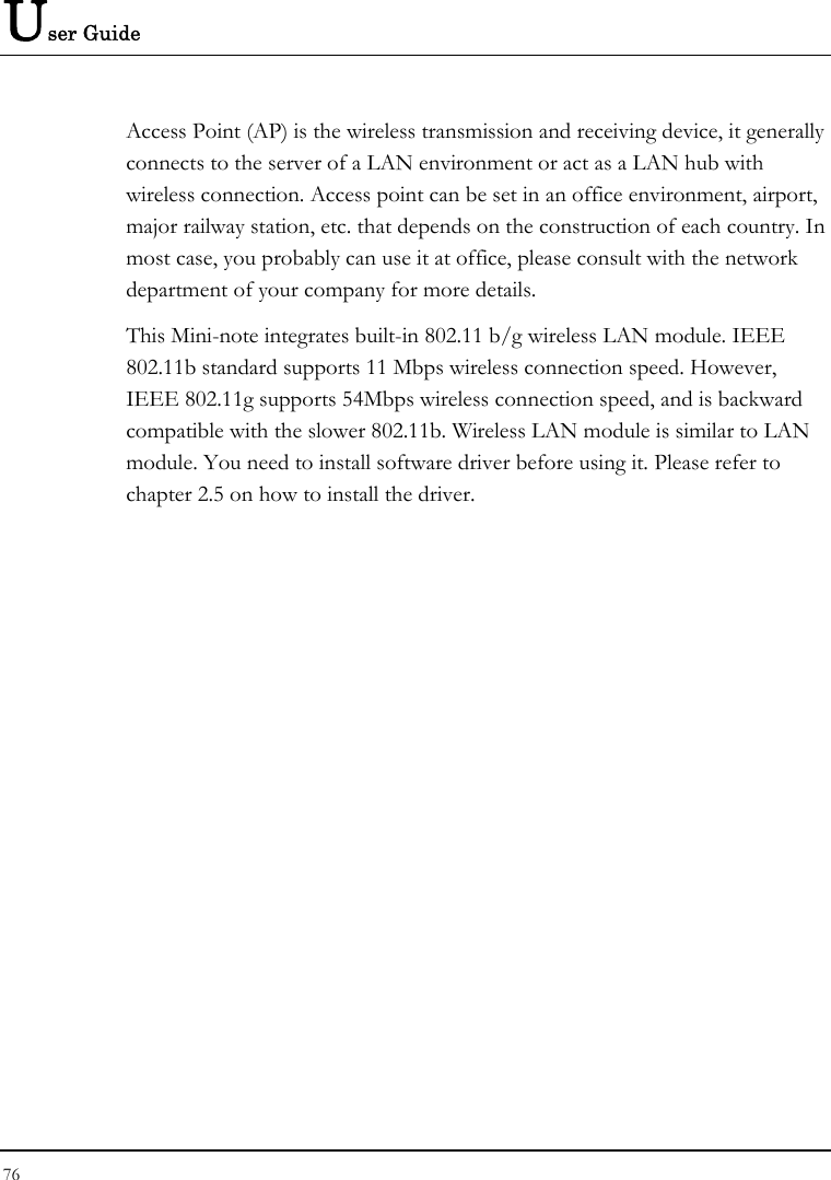
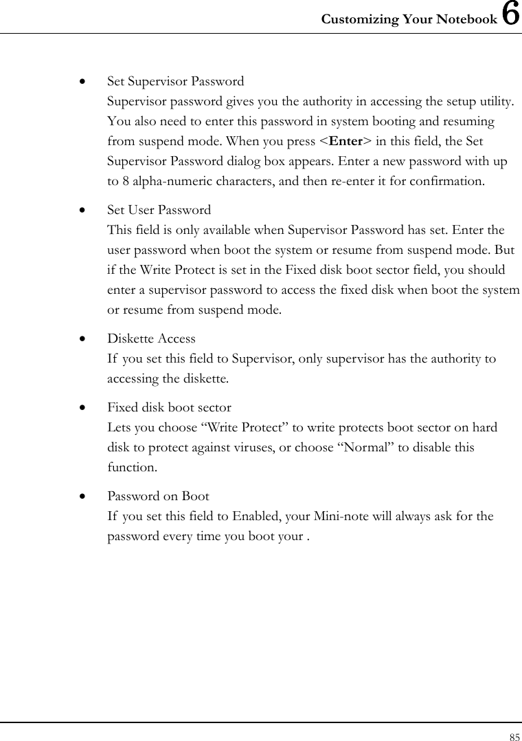
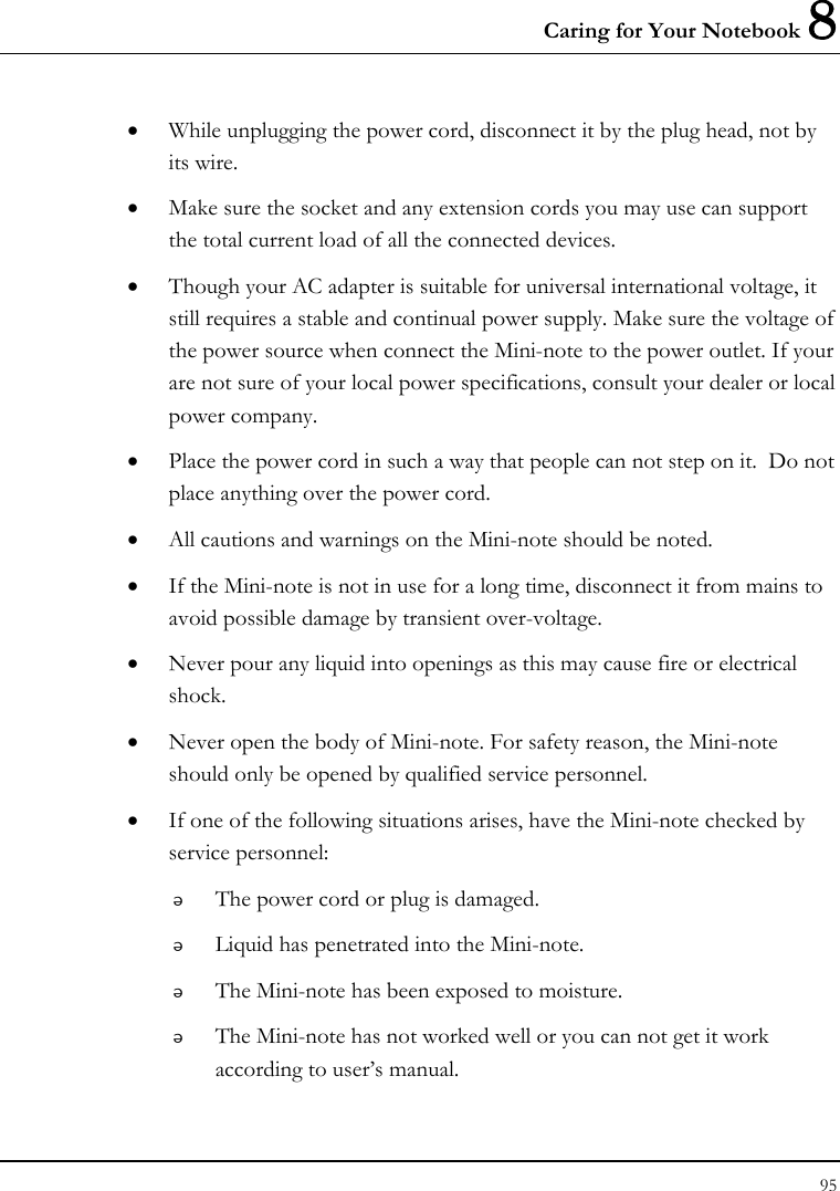
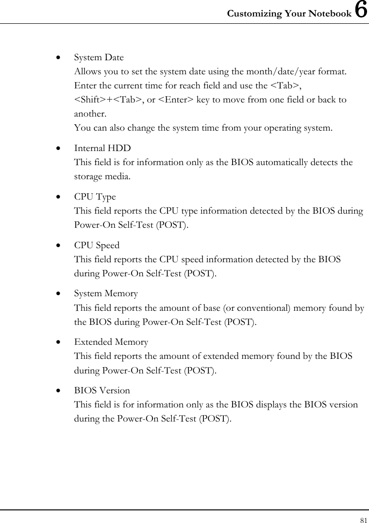
![User Guide 80 6.2 Using the Main Menu Setup Phoenix BIOS Setup Utility Main Advanced Security Boot Exit Item Specific Help System Time: [07 :54 :32] <Tab>, <Shift-Tab>, System Date: [06/11/2008] or <Enter> selects field. 4Internal HDD [SAMSUNG HS06THB-(SM)] CPU Type: VIA C7-M Processor 1200MHz CPU Speed: 1200 MHz System Memory: 640 KB Extended Memory: 916480 KB BIOS Version: 0.4A-0302-0018 F1 Help Ç È Select Item F5/F6 Change Values F9 Setup Defaults Esc Exit Å--> Select Menu Enter Select Sub-Menu F10 Save and Exit • System Time Allows you to change the system time using the hour:minute:second format of the . Enter the current time for reach field and use the <Tab>, <Shift>+<Tab>, or <Enter> key to move from one field or back to another. You can also change the system time from your operating system.](https://usermanual.wiki/First-Computer/CE2A1A/User-Guide-989574-Page-80.png)
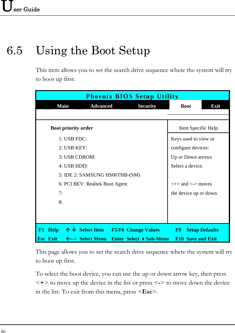
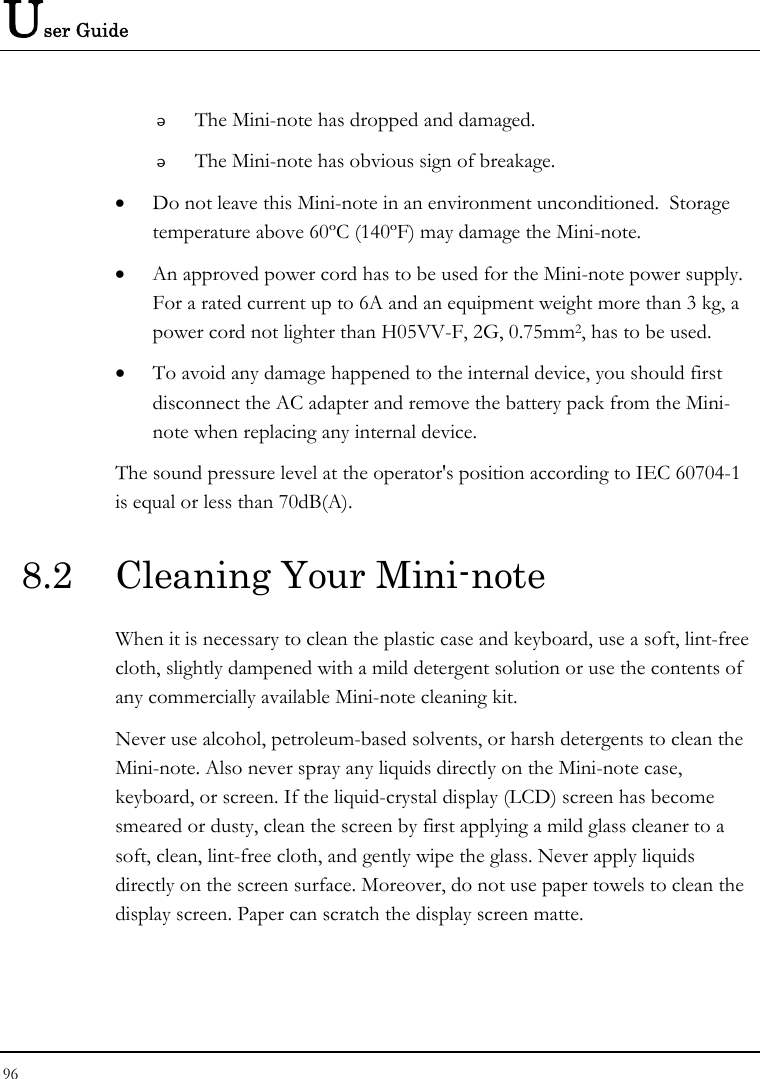
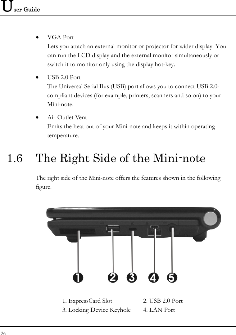
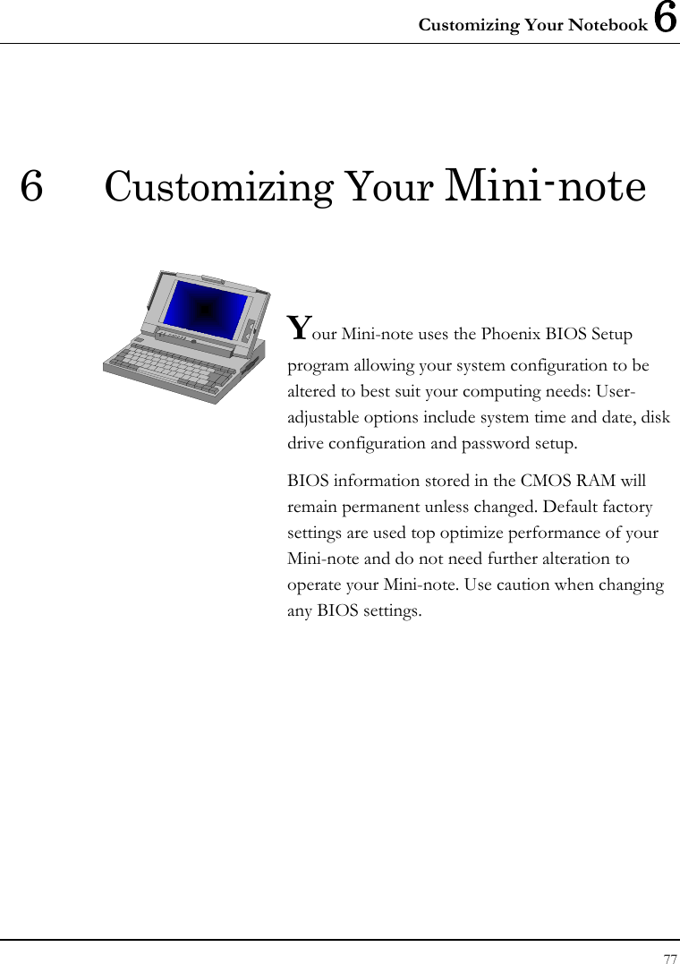
![User Guide 82 6.2.1 INTERNAL HDD SUB-MENU Phoenix BIOS Setup Utility Main Internal HDD [SAMSUNG HS06THB-(SM)] Item Specific Help Type: [Auto] Auto = autotypes LBA Format hard-disk drive Total Sector: 117210240 Installed here. Maximum Capacity: 60012 MB Multi-Sector Transfers: [16 Sectors] LBA Mode Control: [Enabled] 32 Bit I/O: [Disabled] Transfer Mode: [FPIO 4 / DMA 2] Ultra DMA Mode: [Mode 5] SMART Monitoring: Enabled F1 Help Ç È Select Item F5/F6 Change Values F9 Setup Defaults Esc Exit Å--> Select Menu Enter Select Sub-Menu F10 Save and Exit Use the Type field to select the drive type installed. You can select different drive types as CD-ROM, User, Auto or None by pressing <Space> bar. Set this option to Auto so your Mini-note will automatically detect the drive type during power on. Set this option to None when your Mini-note is not installed any devices. Press <Esc> to return to the Main Menu.](https://usermanual.wiki/First-Computer/CE2A1A/User-Guide-989574-Page-82.png)
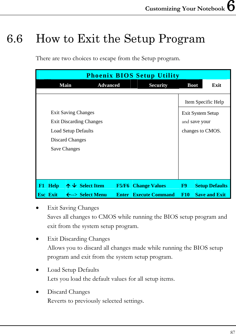
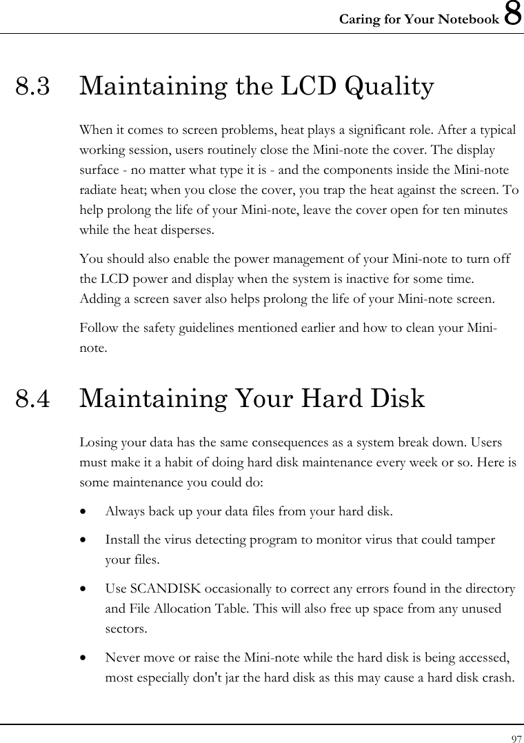
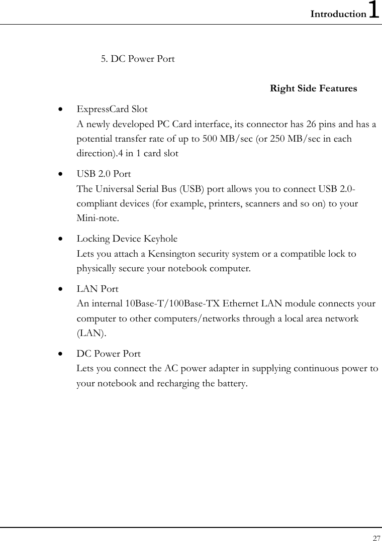
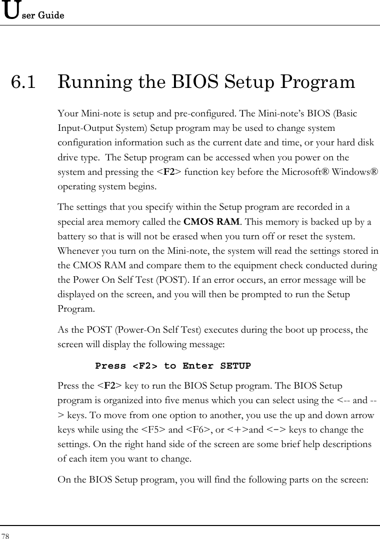
![Customizing Your Notebook 6 83 6.3 Using the Advanced CMOS Setup Phoenix BIOS Setup Utility Main Advanced Security Boot Exit Item Specific Help Boot-time Diagnostic Screen: [Enabled] Display the diagnostic Frame Buffer Size: [128 MB] screen during boot. Legacy USB Support [Enabled] Energy Star Support [Enabled] . . F1 Help Ç È Select Item F5/F6 Change Values F9 Setup Defaults Esc Exit Å--> Select Menu Enter Select Sub-Menu F10 Save and Exit • Boot-time Diagnostic Screen Lets you choose display or not display the diagnostic screen during system boot. • Frame Buffer Size Lets you specify the Frame Buffer Size to 64MB, 128MB, or 256MB. • Legacy USB Support Enable or disable the USB Bus support when in connection with USB device. • Energy Star Support Lets you activate or inactivate the function of Energy Star Support.](https://usermanual.wiki/First-Computer/CE2A1A/User-Guide-989574-Page-83.png)
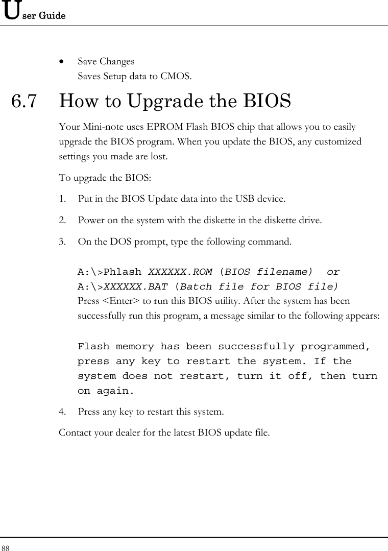
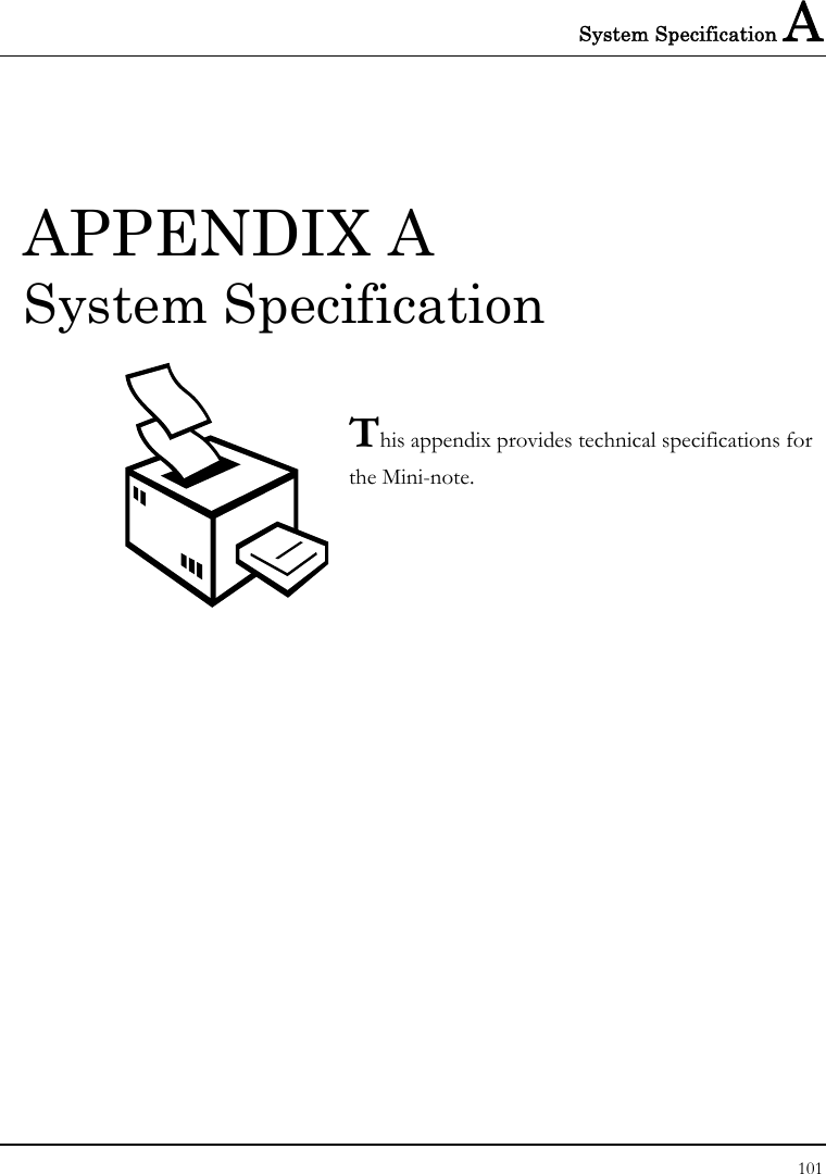
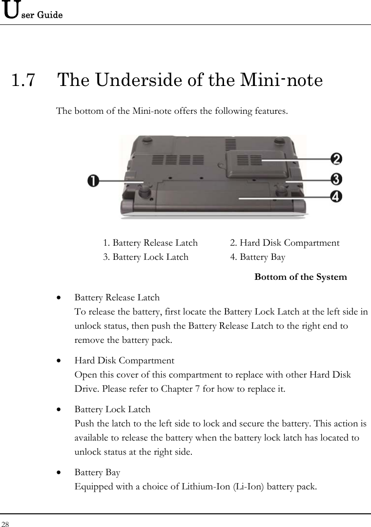
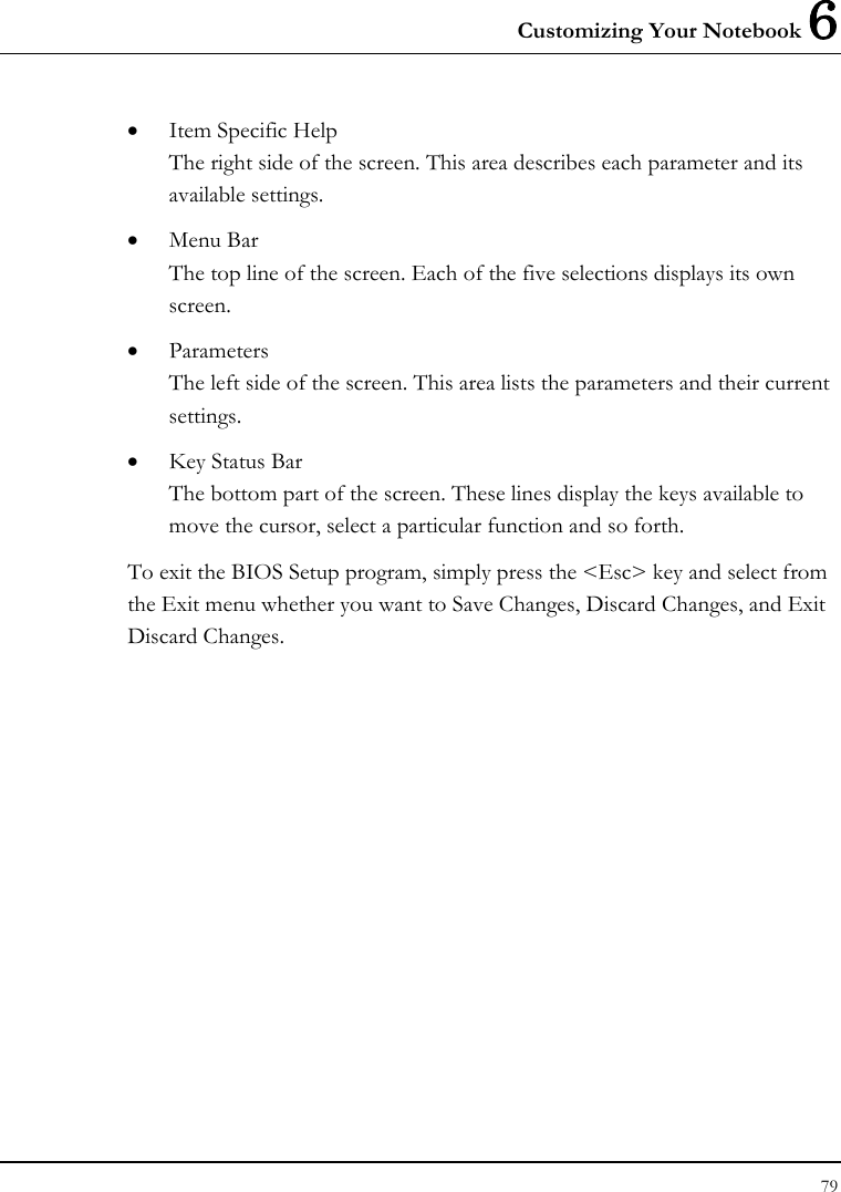
![User Guide 84 6.4 Security Menu Setup Phoenix BIOS Setup Utility Main Advanced Security Boot Exit Item Specific Help Supervisor Password Is: Clear User Password Is: Clear Supervisor Password controls access to the Set Supervisor Password [Enter] setup utility. Set User Password [Enter] Diskette Access [Supervisor] Fixed disk boot sector: [Normal] Password on boot [Disabled] F1 Help Ç È Select Item F5/F6 Change Values F9 Setup Defaults Esc Exit Å--> Select Menu Enter Select Sub-Menu F10 Save and Exit • Supervisor Password Is Set/Clear selections show that the Mini-note is under controlled by Supervisor Password or not. • User Password Is Set/Clear selections show that the Mini-note is under controlled by User Password or not.](https://usermanual.wiki/First-Computer/CE2A1A/User-Guide-989574-Page-84.png)