First Computer CW001-02 Notebook User Manual
First International Computer Inc Notebook
UserManual.wiki
>
First Computer
>
CW001 02 User Manual
Users Manaul
Navigation menu
Upload a User Manual
Namespaces
Wiki Guide
HTML
PDF
Info
Views
User Manual
Discussion / Help
Navigation
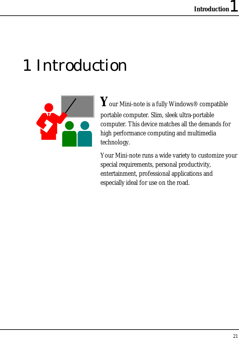
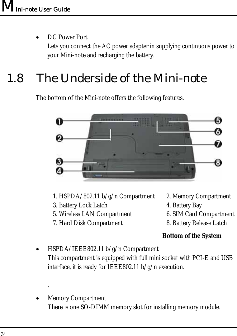
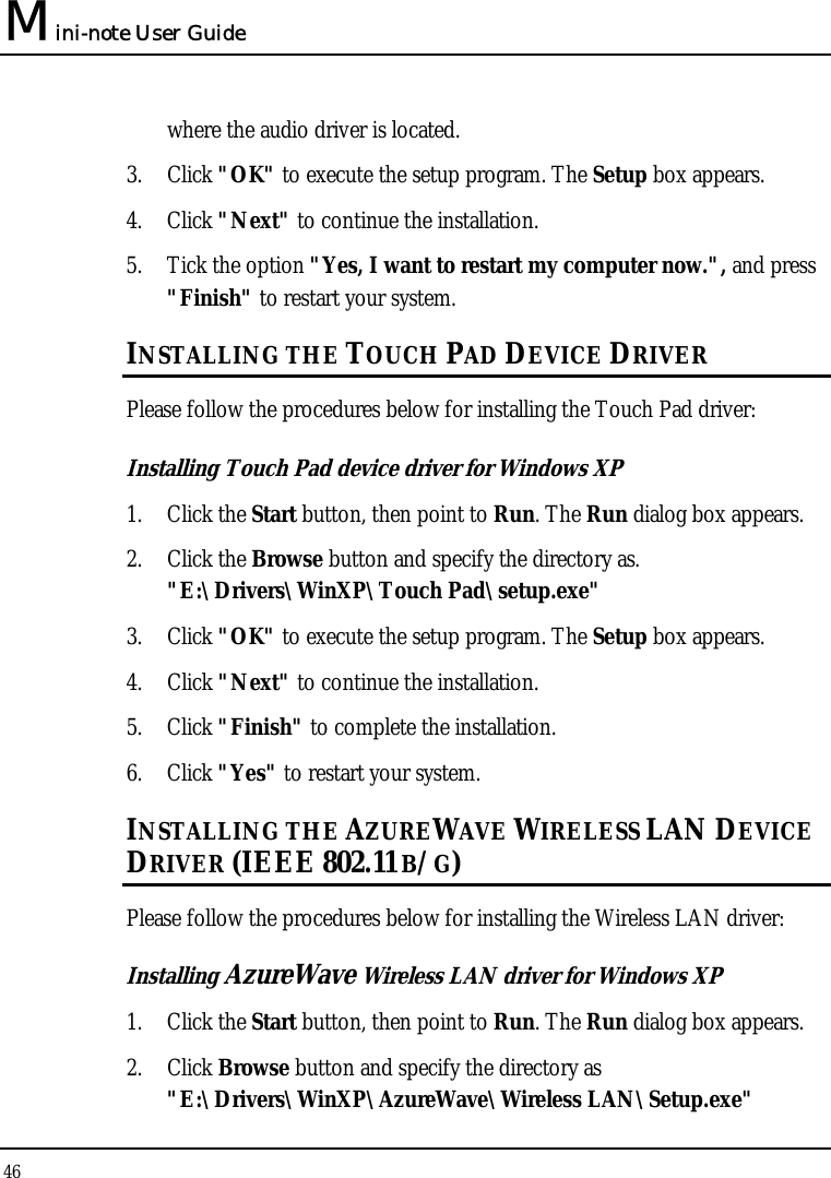

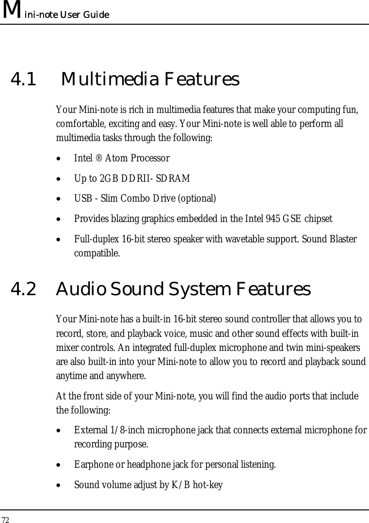
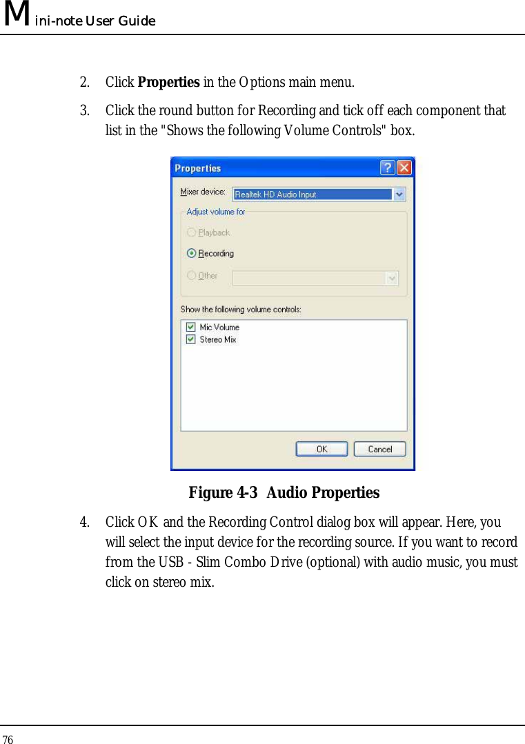

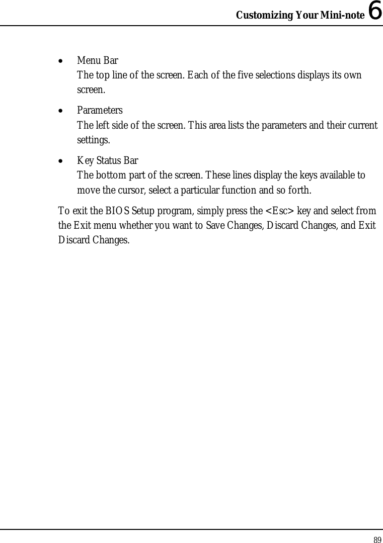
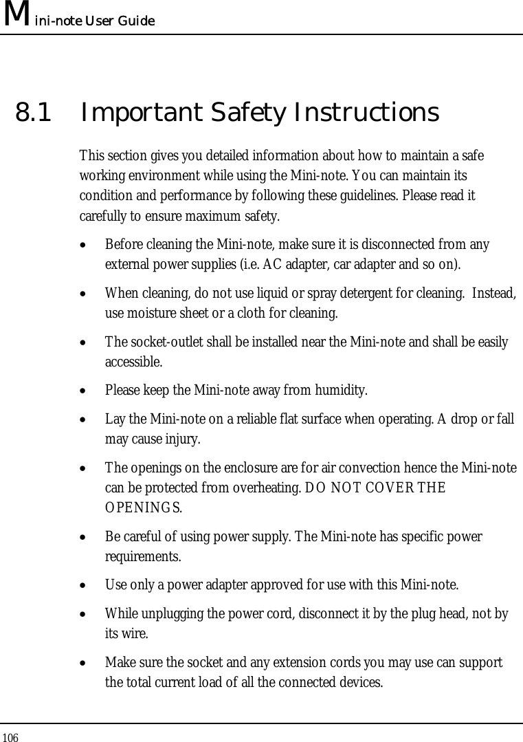
![Mini-note User Guide 90 6.2 Using the Main Menu Setup Phoenix BIOS Setup Utility Main Advanced Security Boot Exit Item Specific Help System Time:[07 :54 :32] <Tab>, <Shift-Tab>, System Date: [10/28/2008] or <Enter> selects field. BIOS revision: IMB05 IDE Channel 0 Master FUJITSU MHZ2120BH G2-(S1) CPU Type: Intel (R) Atom(TM) CPU N270 CPU Speed: 1600 MHz System Memory: 640 KB Extended Memory: 1038336 KB F1 Help Ç ÈSelect Item ─ / + Change Values F9 Setup Defaults Esc Exit ÅÎ Select Menu Enter Select Sub-Menu F10 Save and Exit • System Time Allows you to change the system time using the hour:minute:second format of the . Enter the current time for reach field and use the <Tab>, <Shift>+<Tab>, or <Enter> key to move from one field or back to another. You can also change the system time from your operating system.](https://usermanual.wiki/First-Computer/CW001-02/User-Guide-1063312-Page-90.png)
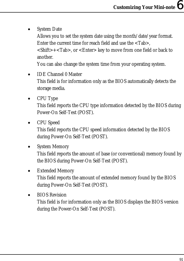
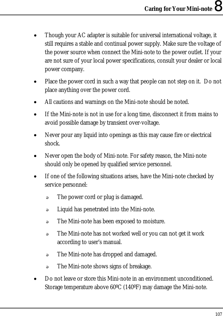
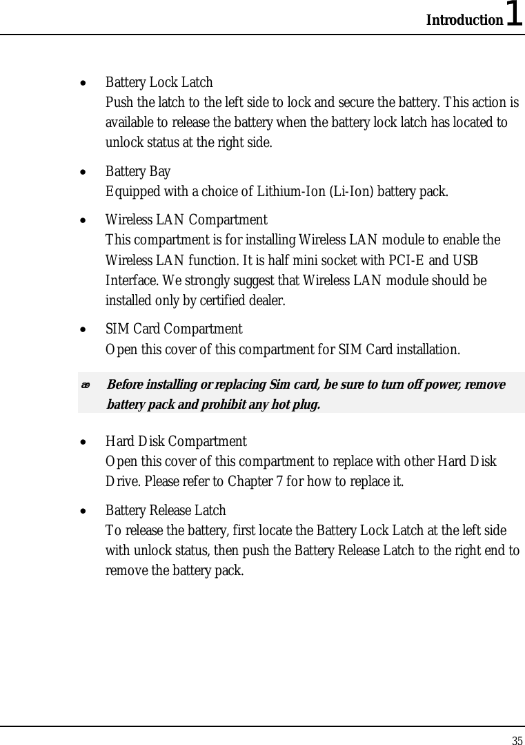
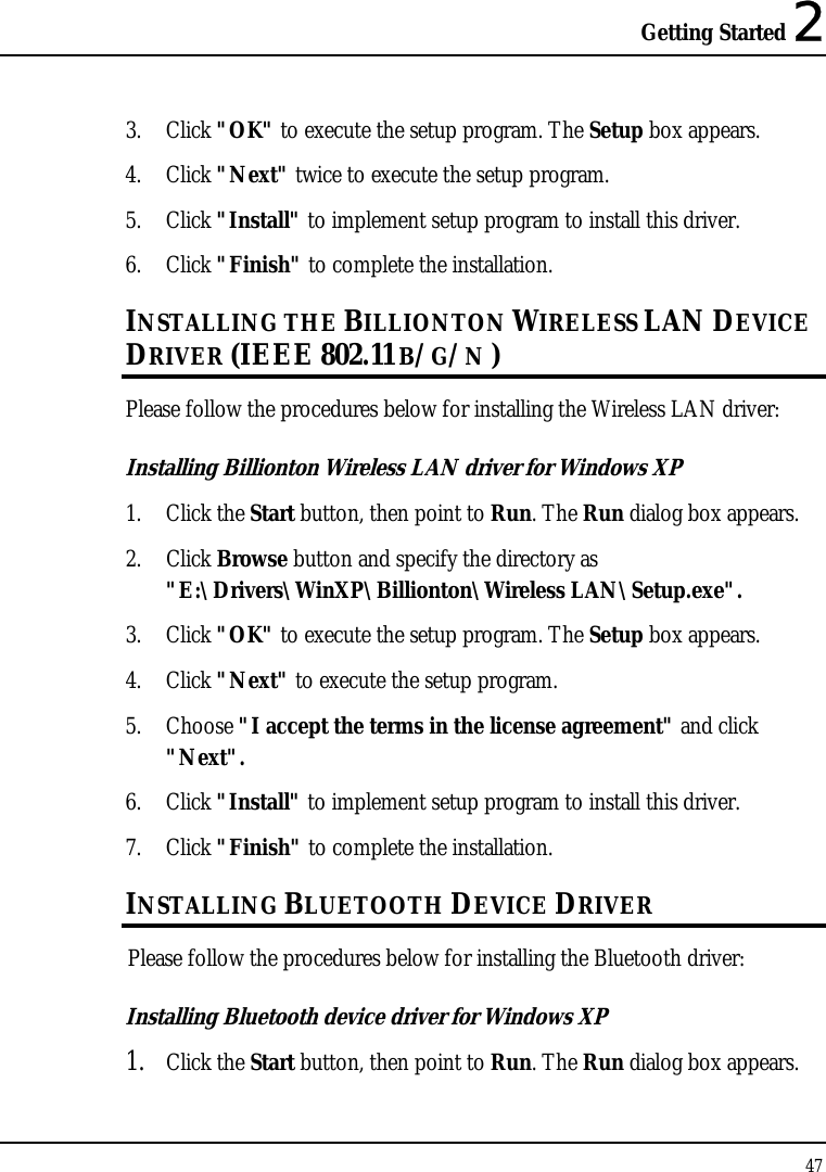
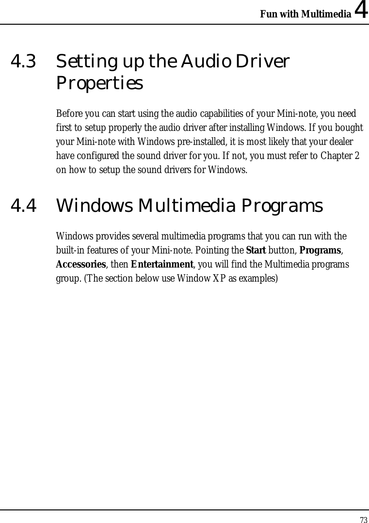
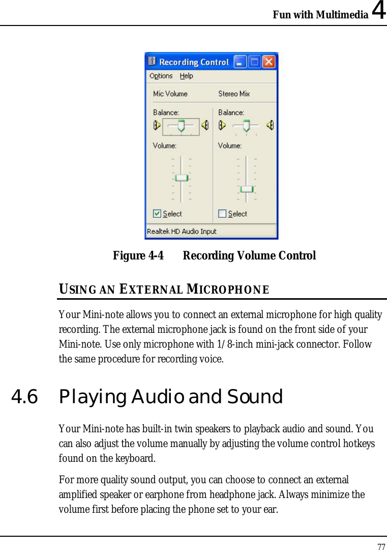
![Mini-note User Guide 92 6.3 Using the Advanced CMOS Setup Phoenix BIOS Setup Utility Main Advanced Security Boot Exit Item Specific Help Legacy USB Support [Enabled] Enable support for USB – Device 29, Function 7: [Enabled] Legacy Universal Serial Boot-time Diagnostic Screen: [Disabled] Bus Total Graphics Memory [MaxDVMT] DVMT Graphics Memory 216MB Energy Star Support [Enabled] F1 Help Ç È Select Item ─ / + Change Values F9 Setup Defaults Esc Exit ÅÎ Select Menu Enter Select Sub-Menu F10 Save and Exit • Legacy USB Support Enable or Disable the Legacy Universal Serial Bus support • USB – Device 29, Function 7 Enable or Disable the USB 2.0 controller support. • Boot-time Diagnostic Screen Lets you choose display or not display the diagnostic screen during system boot.](https://usermanual.wiki/First-Computer/CW001-02/User-Guide-1063312-Page-92.png)
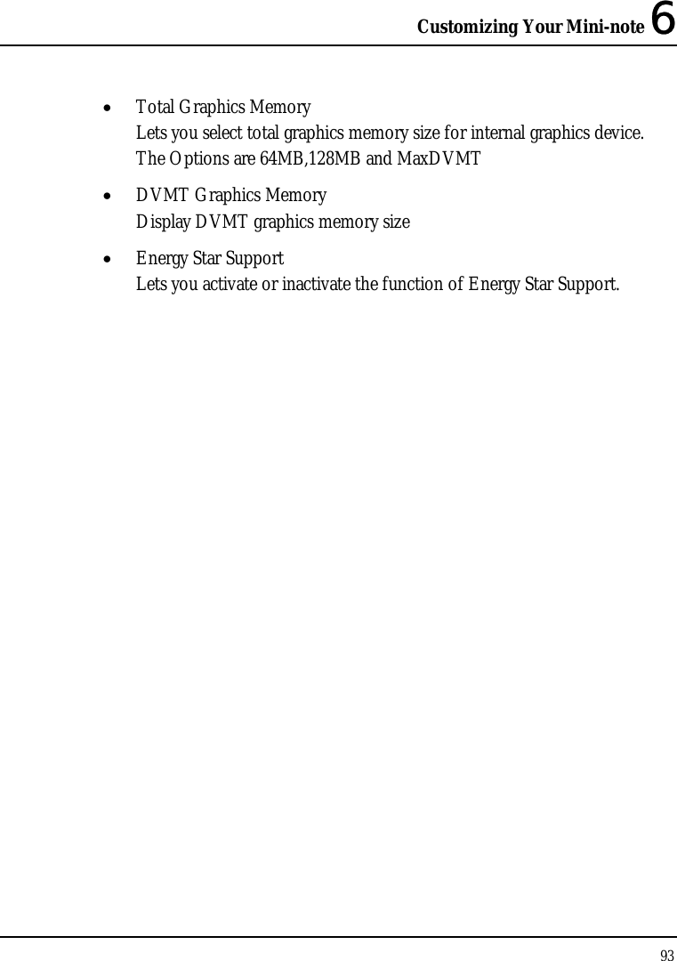
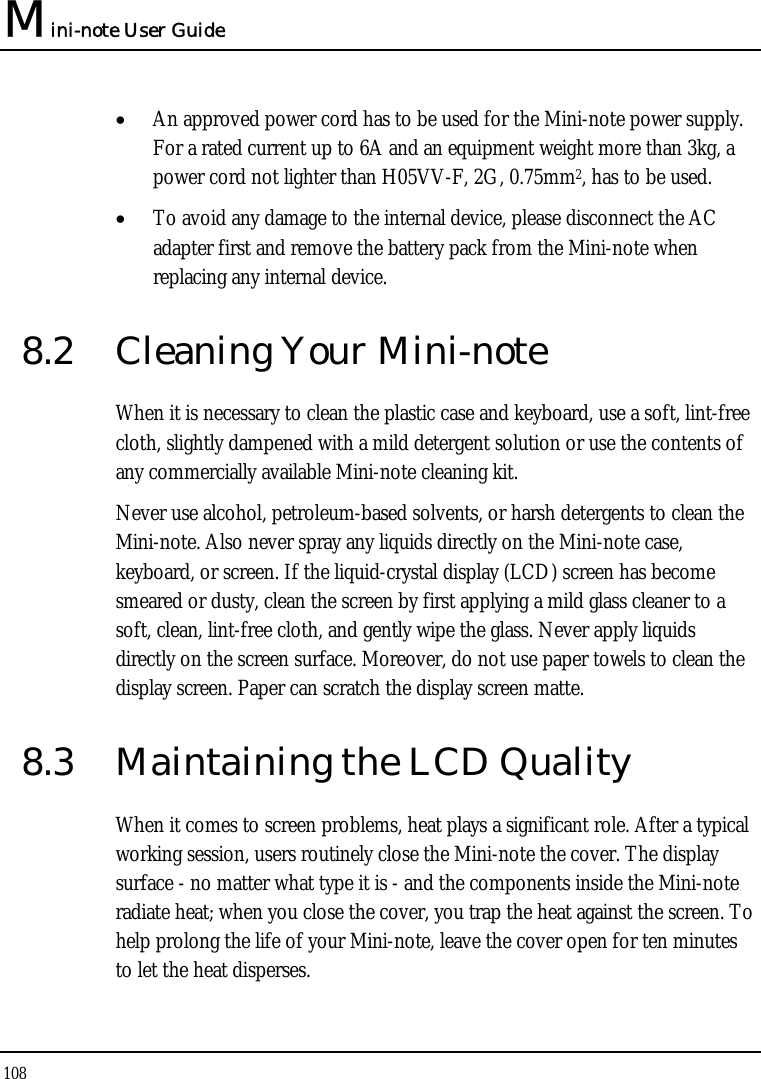
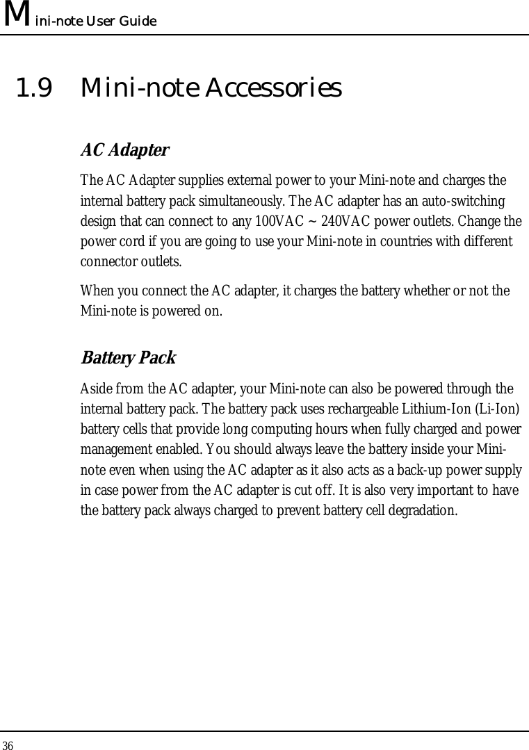
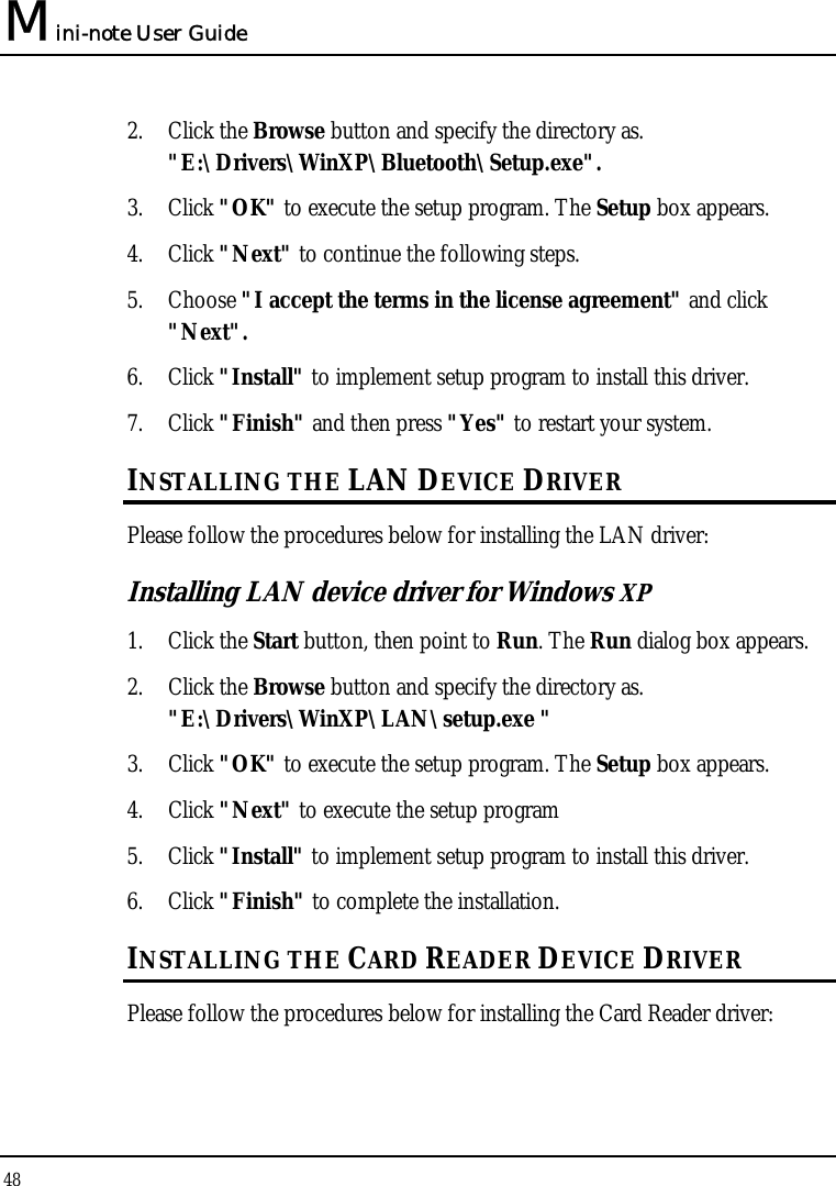
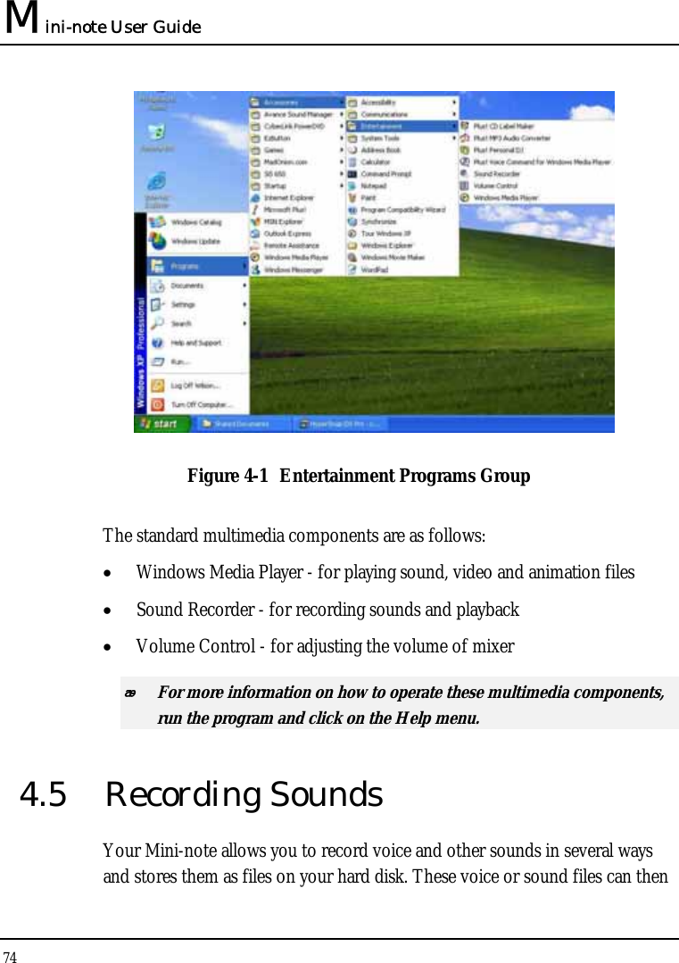
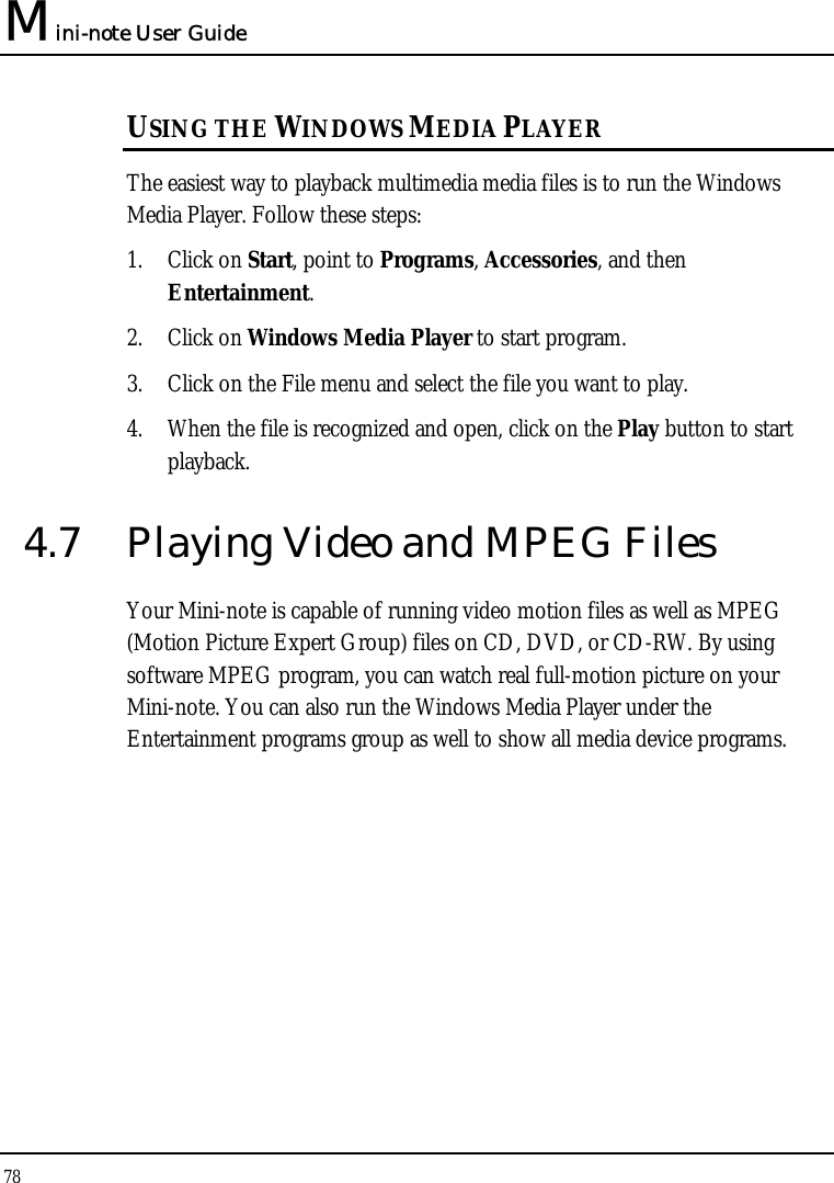
![Mini-note User Guide 94 6.4 Security Menu Setup Phoenix BIOS Setup Utility Main Advanced Security Boot Exit Item Specific Help Supervisor Password Is: Clear User Password Is: Clear Supervisor Password controls access to the Set Supervisor Password [Enter] setup utility. Set User Password [Enter] Password on boot [Disabled] F1 Help Ç ÈSelect Item ─ / + Change Values F9 Setup Defaults Esc Exit ÅÎ Select Menu Enter Select Sub-Menu F10 Save and Exit • Supervisor Password Is Set/Clear selections show that the Mini-note is under controlled by Supervisor Password or not. • User Password Is Set/Clear selections show that the Mini-note is under controlled by User Password or not. • Set Supervisor Password Supervisor password gives you the authority in accessing the setup utility. You also need to enter this password in system booting and resuming from suspend mode. When you press <Enter> in this field, the Set Supervisor Password dialog box appears. Enter a new password with up to 8 alpha-numeric characters, and then re-enter it for confirmation.](https://usermanual.wiki/First-Computer/CW001-02/User-Guide-1063312-Page-94.png)
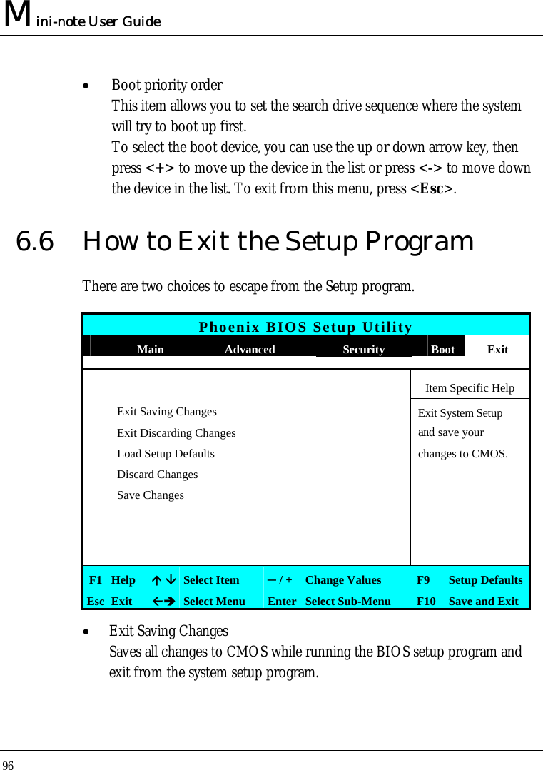
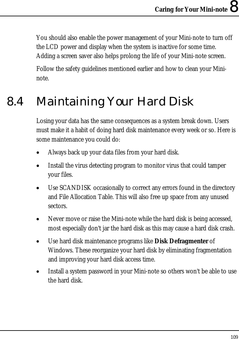
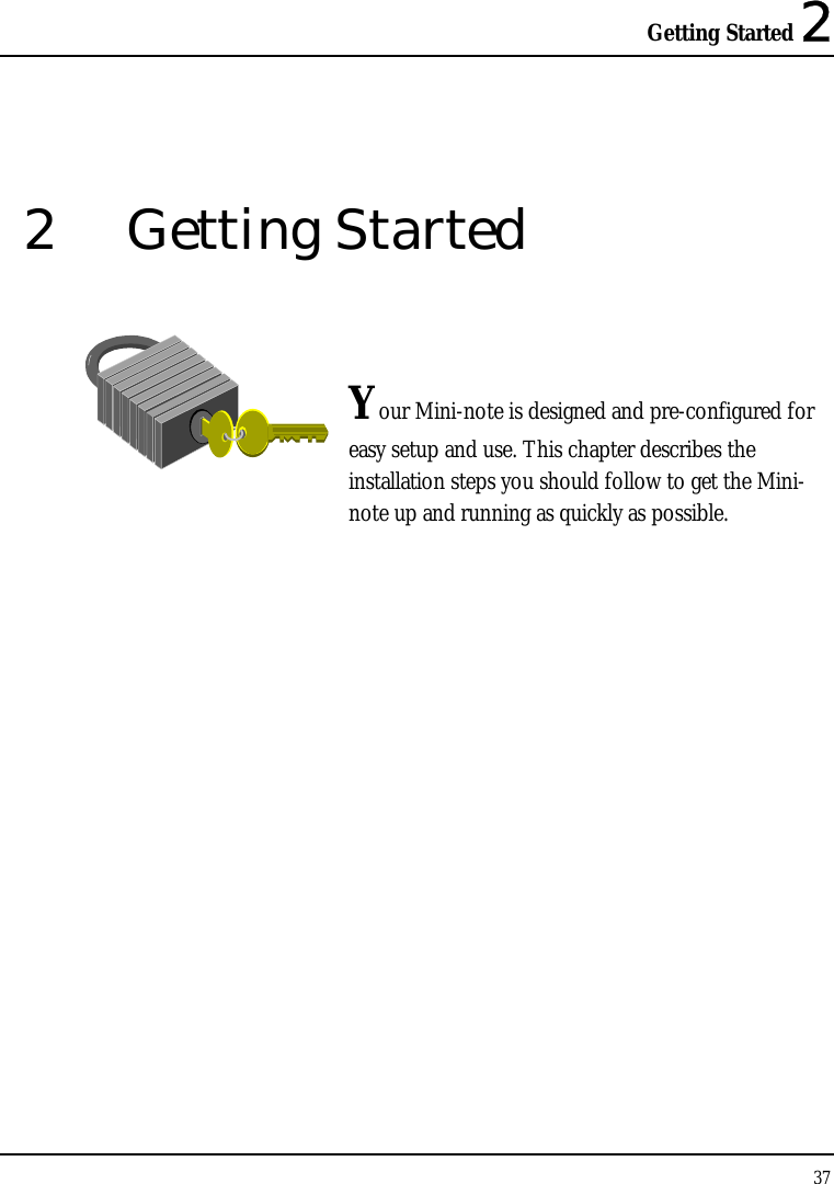
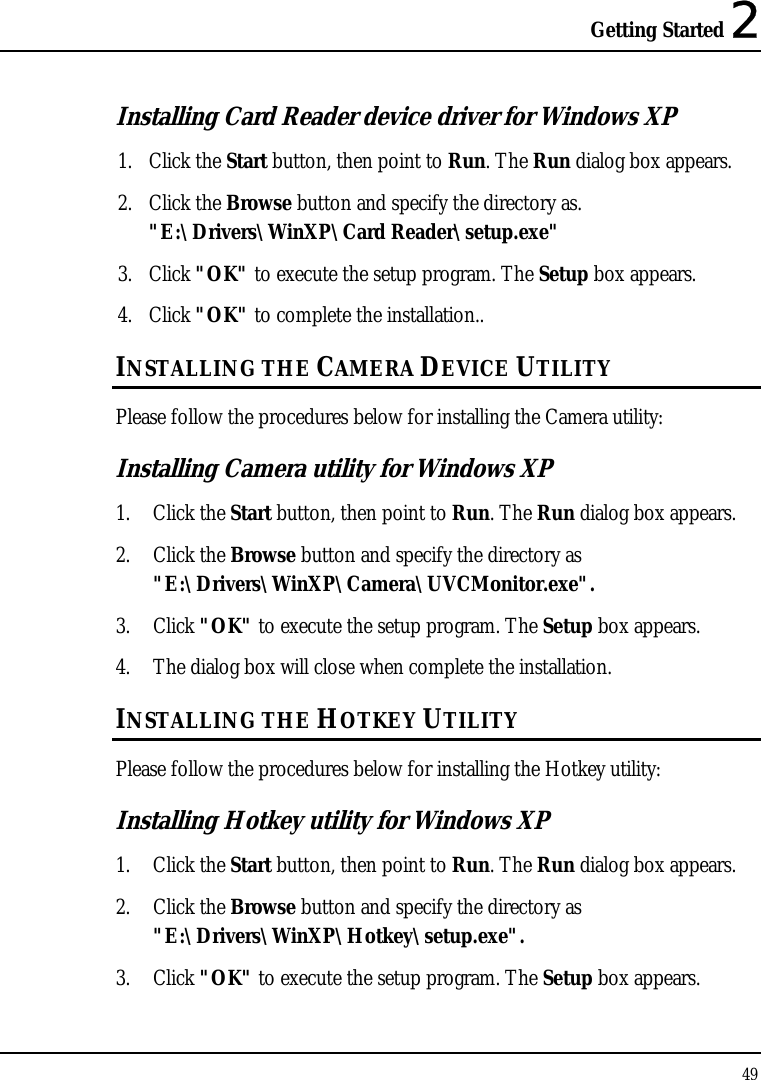
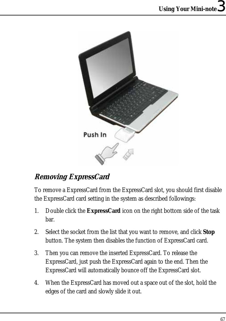
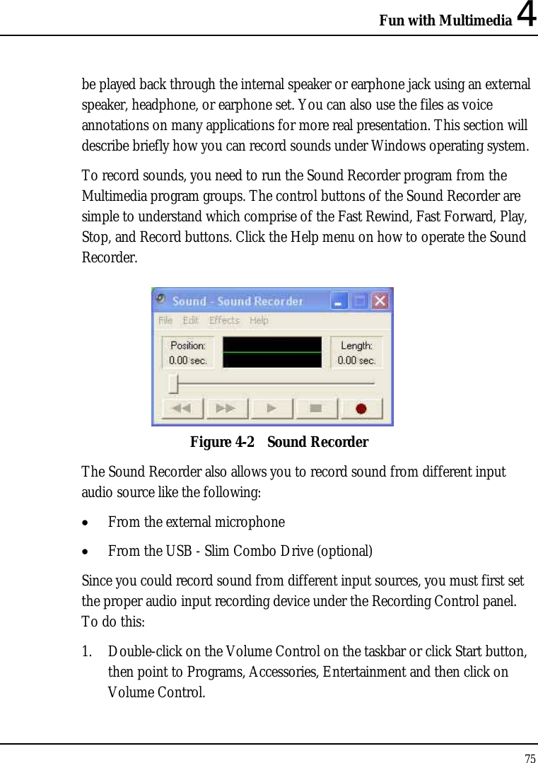
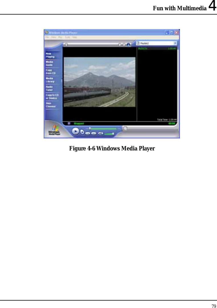
![Customizing Your Mini-note 6 95 • Set User Password Enter the user password when boot the system or resume from suspend mode. • Password on Boot If you set this field to Enabled, your Mini-note will always ask for the password every time you boot your . 6.5 Using the Boot Setup This item allows you to set the search drive sequence where the system will try to boot up first. Phoenix BIOS Setup Utility Main Advanced Security Boot Exit LAN BOOT: [Disabled] Item Specific Help Enable LAN boot. Boot priority order 1: USB FDC: 2: USB CDROM: 3: USB KEY: 4: USB HDD: 5: IDE HDD: FUJITSU MHZ2120BH G2-(S1) 6: PCI BEV F1 Help Ç ÈSelect Item ─ / + Change Values F9 Setup Defaults Esc Exit ÅÎ Select Menu Enter Select Sub-Menu F10 Save and Exit • LAN Boot Lets you Enable or Disable the LAN boot function.](https://usermanual.wiki/First-Computer/CW001-02/User-Guide-1063312-Page-95.png)