First Computer CW0A1A CW0A1 Mini Note User Manual XP CW0A1 Manual
First International Computer Inc CW0A1 Mini Note XP CW0A1 Manual
UserManual.wiki
>
First Computer
>
CW0A1A User Manual
>
manual
Contents
1.
manual
2.
user manual
manual
Navigation menu
Upload a User Manual
Namespaces
Wiki Guide
HTML
PDF
Info
Views
User Manual
Discussion / Help
Navigation
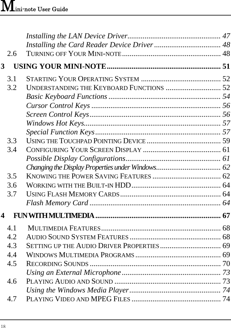

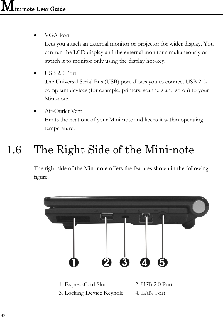


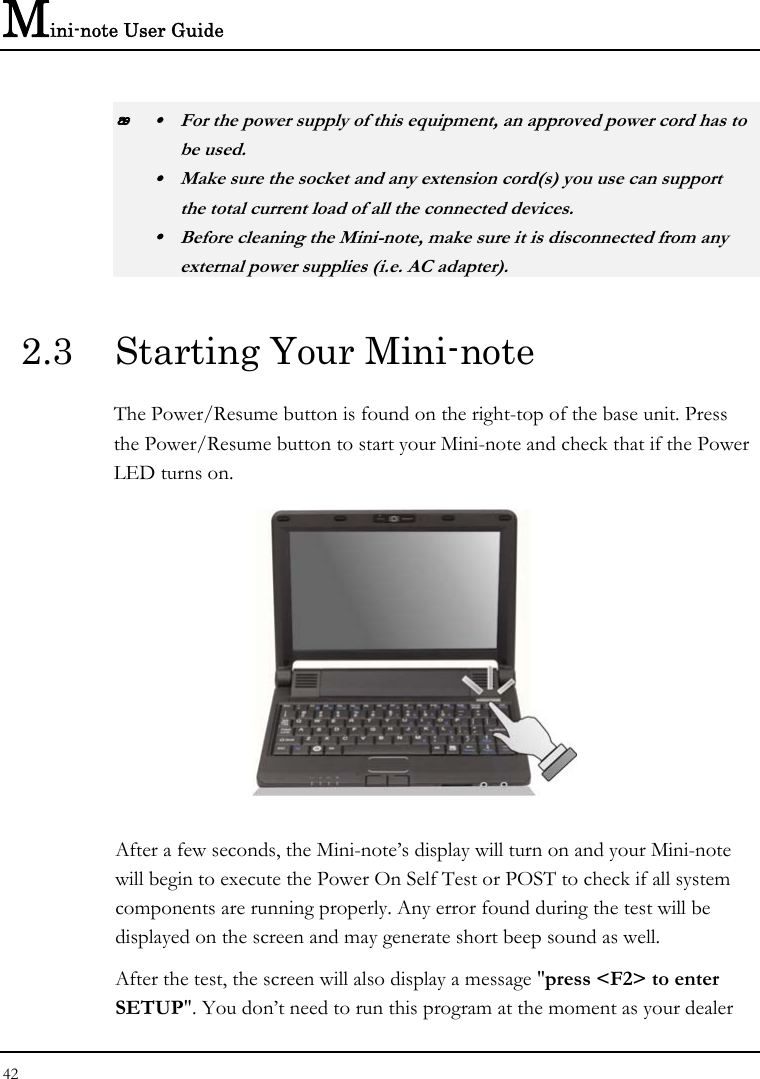

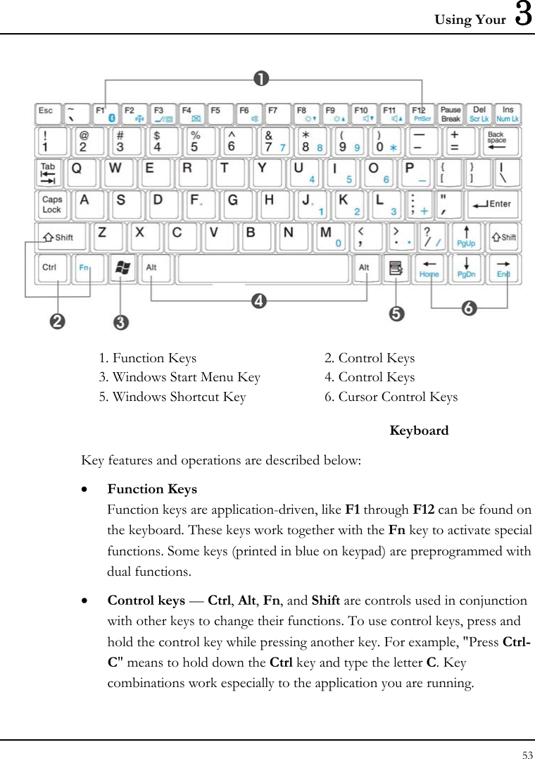


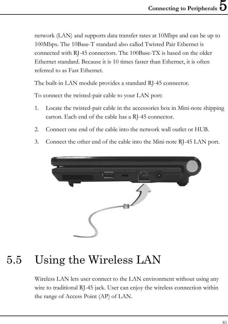
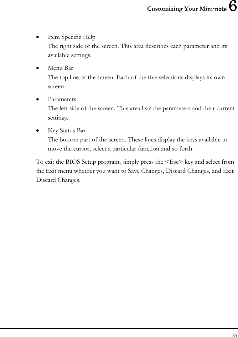
![Mini-note User Guide 86 6.2 Using the Main Menu Setup Phoenix BIOS Setup Utility Main Advanced Security Boot Exit Item Specific System Time: [07 :54 :32] <Tab>, <Shift- System Date: [09/02/2008] or <Enter> selects field. 4IDE Channel 0 Master [TOSHIBA MK6028GAL-(PM)] CPU Type: Intel (R) Atom(TM) CPU N270 CPU Speed: 1.60GHz System Memory: 640 KB Extended Memory: 916480 KB BIOS Version: 0.4A-1585-0018 F1 Help Ç È Select Item F5/F6 Change Values F9 Setup Defaults Esc Exit Å--> Select Menu Enter Select Sub-Menu F10 Save and Exit • System Time Allows you to change the system time using the hour:minute:second format of the . Enter the current time for reach field and use the <Tab>, <Shift>+<Tab>, or <Enter> key to move from one field or back to another. You can also change the system time from your operating system.](https://usermanual.wiki/First-Computer/CW0A1A.manual/User-Guide-1001029-Page-86.png)
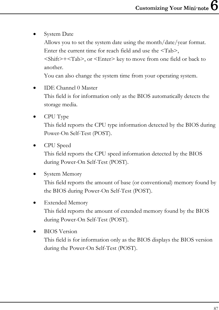
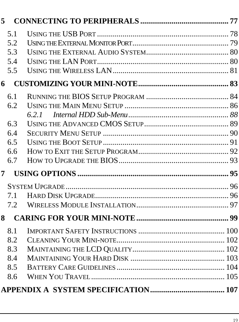
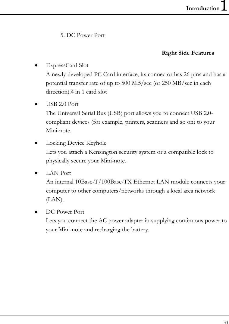
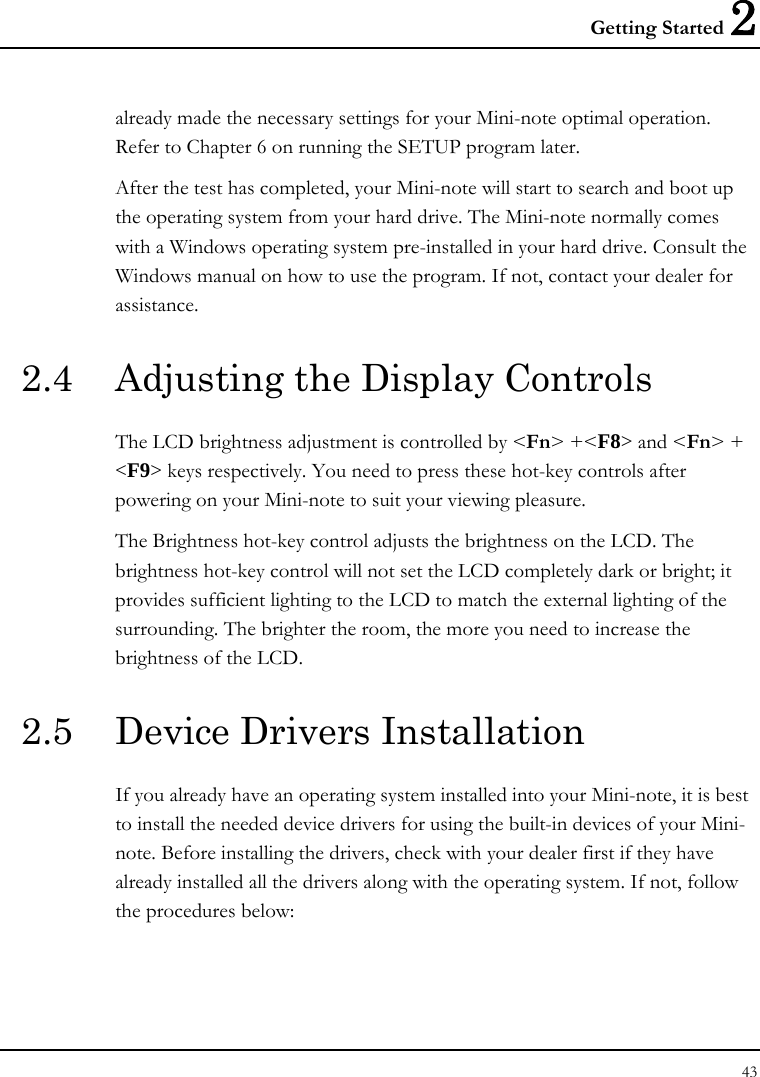
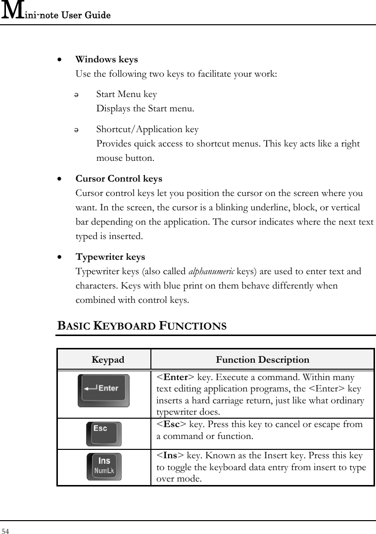
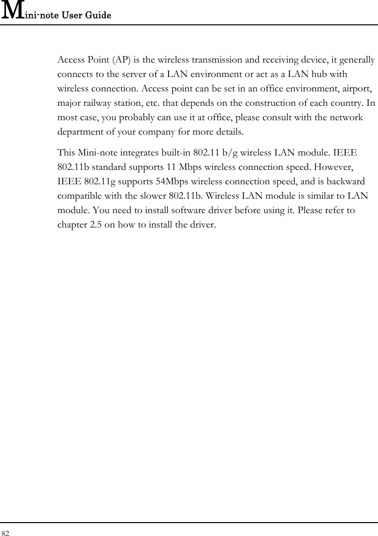
![Mini-note User Guide 88 6.2.1 INTERNAL HDD SUB-MENU Phoenix BIOS Setup Utility Main IDE Channel 0 Master [TOSHIBA MK6028GAL- Item Specific Help Type: [Auto] User = you enter LBA Format parameters of hard-disk drive Total Sector: 117210240 installed at this connection. Maximum Capacity: 60012 MB Auto = autotypes hard-disk drive installed here. Multi-Sector Transfers: [16 Sectors] CD-ROM = a CD-ROM LBA Mode Control: [Enabled] drive is installed here. 32 Bit I/O: [Disabled] ATAPI Removable = Transfer Mode: [FPIO 4 / DMA 2] removable disk drive is Ultra DMA Mode: [Mode 5] installed here. SMART Monitoring: Enabled F1 Help Ç È Select Item F5/F6 Change Values F9 Setup Defaults Esc Exit Å--> Select Menu Enter Select Sub-Menu F10 Save and Exit Use the Type field to select the drive type installed. You can select different drive types as CD-ROM, User, Auto or None by pressing <Space> bar. Set this option to Auto so your Mini-note will automatically detect the drive type during power on. Set this option to None when your Mini-note is not installed any devices. Press <Esc> to return to the Main Menu.](https://usermanual.wiki/First-Computer/CW0A1A.manual/User-Guide-1001029-Page-88.png)
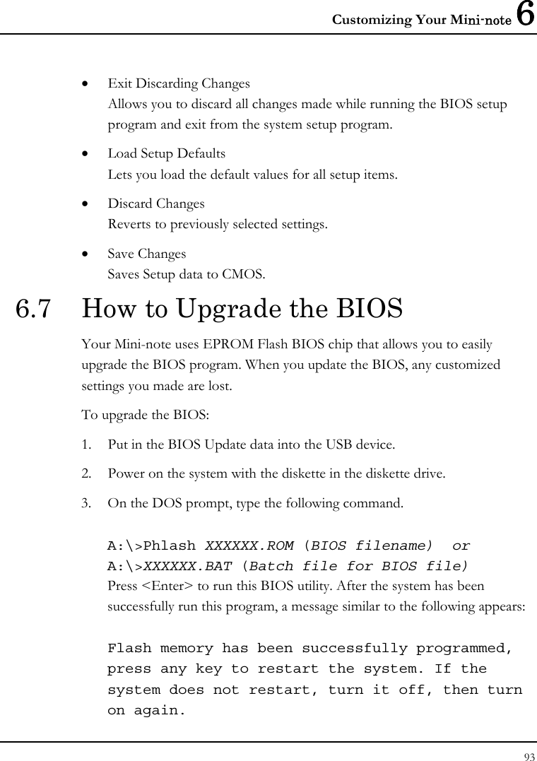
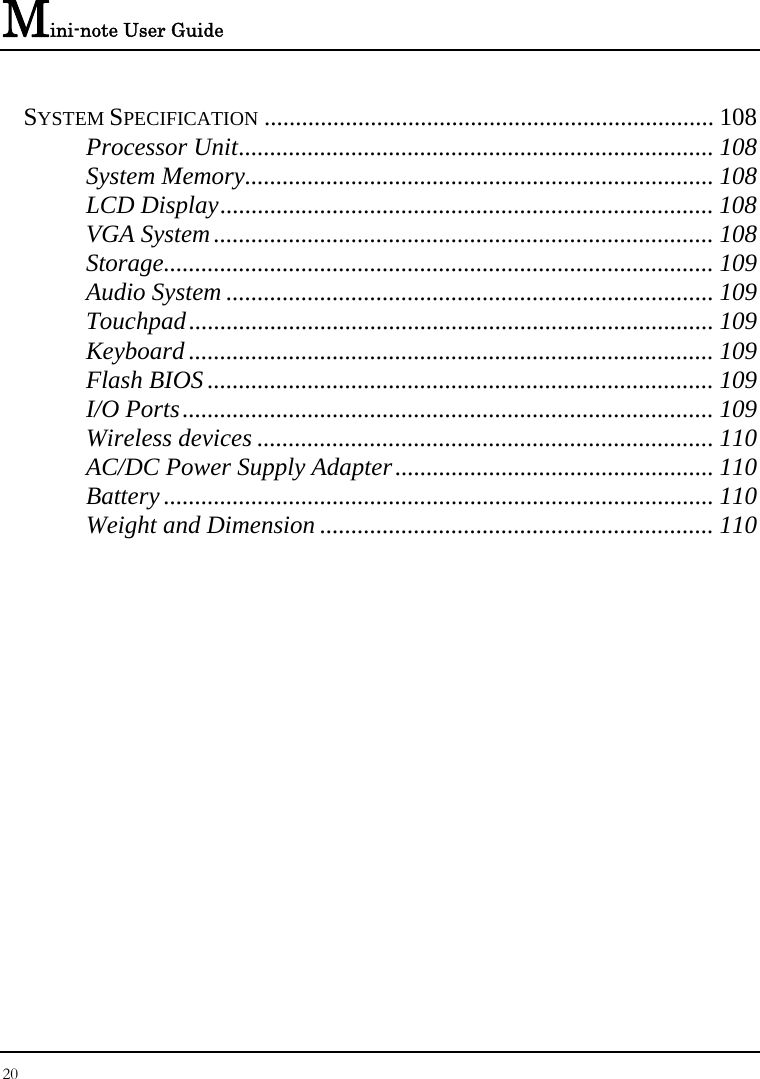
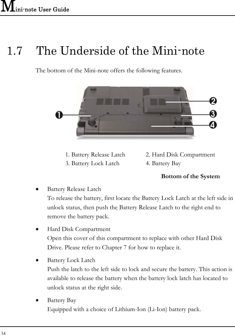
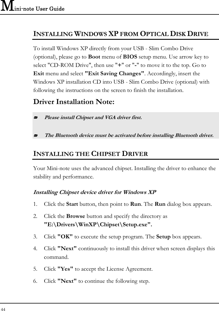
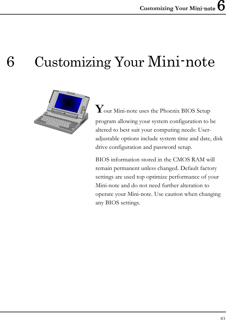
![Customizing Your Mini-note 6 89 6.3 Using the Advanced CMOS Setup Phoenix BIOS Setup Utility Main Advanced Security Boot Exit Item Specific Help Legacy USB Support [Enabled] Display the diagnostic Boot-time Diagnostic Screen: [Enabled] screen during boot. Energy Star Support [Enabled] . . F1 Help Ç È Select Item F5/F6 Change Values F9 Setup Defaults Esc Exit Å--> Select Menu Enter Select Sub-Menu F10 Save and Exit • Legacy USB Support Enable or disable the USB Bus support when in connection with USB device. • Boot-time Diagnostic Screen Lets you choose display or not display the diagnostic screen during system boot. • Energy Star Support Lets you activate or inactivate the function of Energy Star Support.](https://usermanual.wiki/First-Computer/CW0A1A.manual/User-Guide-1001029-Page-89.png)
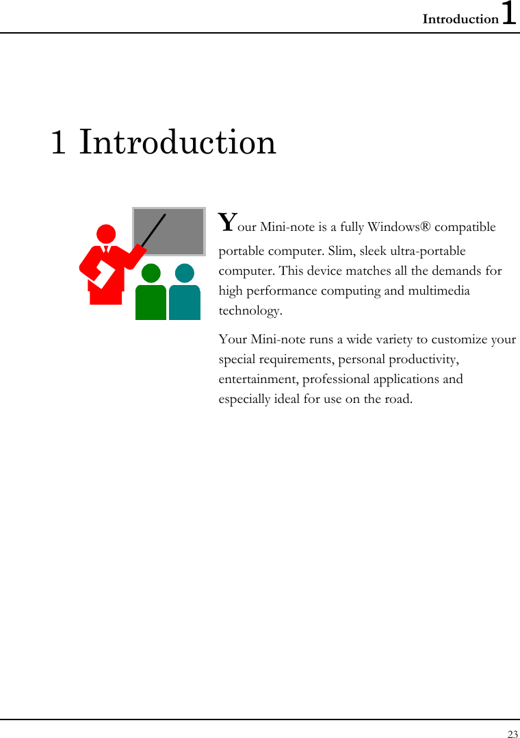
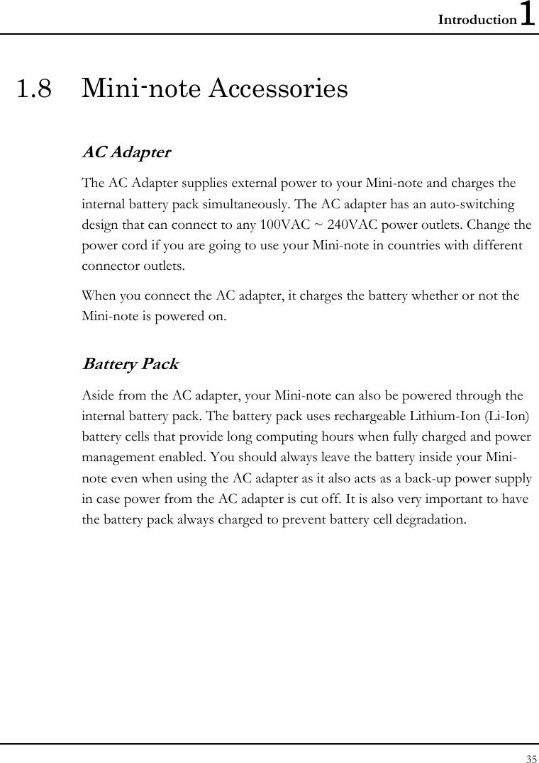
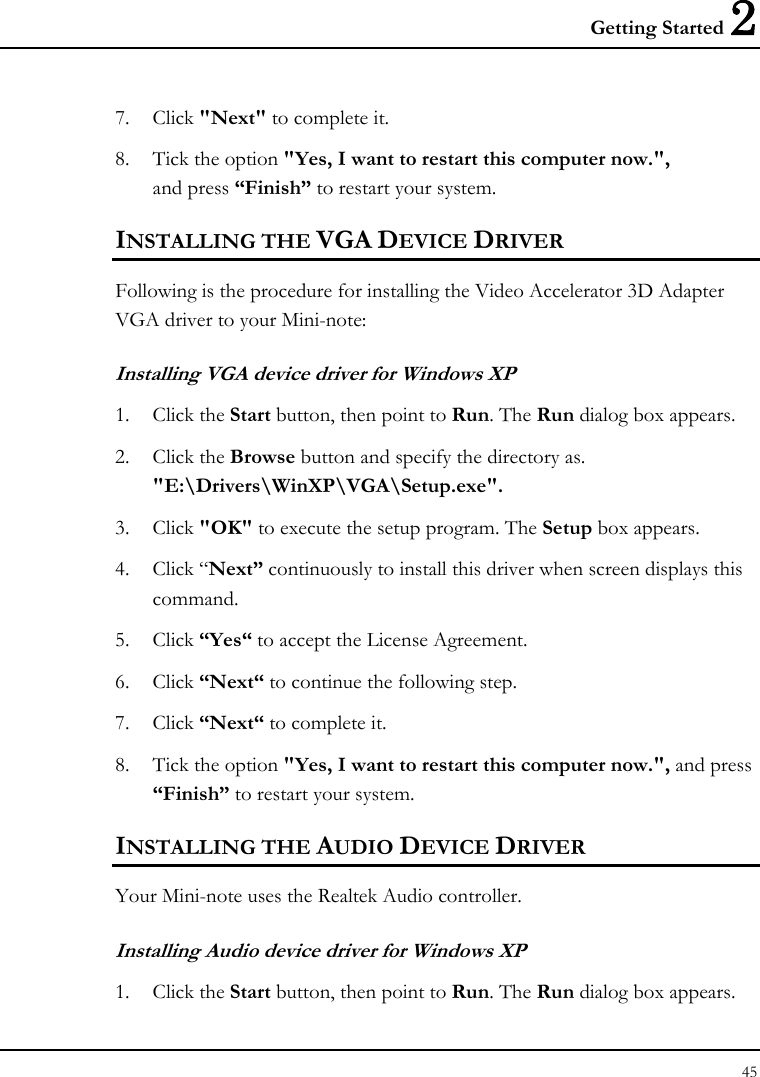
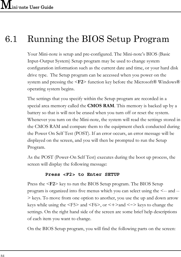
![Mini-note User Guide 90 6.4 Security Menu Setup Phoenix BIOS Setup Utility Main Advanced Security Boot Exit Item Specific Help Supervisor Password Is: Clear User Password Is: Clear Supervisor Password controls access to the Set Supervisor Password [Enter] setup utility. Set User Password [Enter] Password on boot [Disabled] F1 Help Ç È Select Item F5/F6 Change Values F9 Setup Defaults Esc Exit Å--> Select Menu Enter Select Sub-Menu F10 Save and Exit • Supervisor Password Is Set/Clear selections show that the Mini-note is under controlled by Supervisor Password or not. • User Password Is Set/Clear selections show that the Mini-note is under controlled by User Password or not. • Set Supervisor Password Supervisor password gives you the authority in accessing the setup utility. You also need to enter this password in system booting and resuming from suspend mode. When you press <Enter> in this field, the Set Supervisor Password dialog box appears. Enter a new password with up to 8 alpha-numeric characters, and then re-enter it for confirmation.](https://usermanual.wiki/First-Computer/CW0A1A.manual/User-Guide-1001029-Page-90.png)
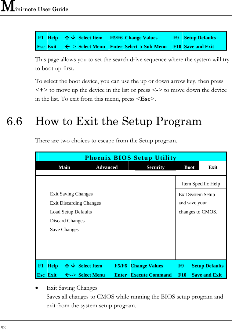
![Customizing Your Mini-note 6 91 • Set User Password This field is only available when Supervisor Password has set. Enter the user password when boot the system or resume from suspend mode. But if the Write Protect is set in the Fixed disk boot sector field, you should enter a supervisor password to access the fixed disk when boot the system or resume from suspend mode. • Password on Boot If you set this field to Enabled, your Mini-note will always ask for the password every time you boot your . 6.5 Using the Boot Setup This item allows you to set the search drive sequence where the system will try to boot up first. Phoenix BIOS Setup Utility Main Advanced Security Boot Exit LAN BOOT: [Disabled] Item Specific Help Enable LAN boot. Boot priority order 1: USB FDC: 2: USB CDROM: 3: IDE CD: 4: USB KEY: 5: USB HDD: 6: IDE HDD: TOSHIBA MK6028GAL-(PM) 7: PCI BEV](https://usermanual.wiki/First-Computer/CW0A1A.manual/User-Guide-1001029-Page-91.png)