First Computer GE2L Notebook PC User Manual GE2 English Manual
First International Computer Inc Notebook PC GE2 English Manual
UserManual.wiki
>
First Computer
>
GE2L User Manual
Users Manual
Navigation menu
Upload a User Manual
Namespaces
Wiki Guide
HTML
PDF
Info
Views
User Manual
Discussion / Help
Navigation
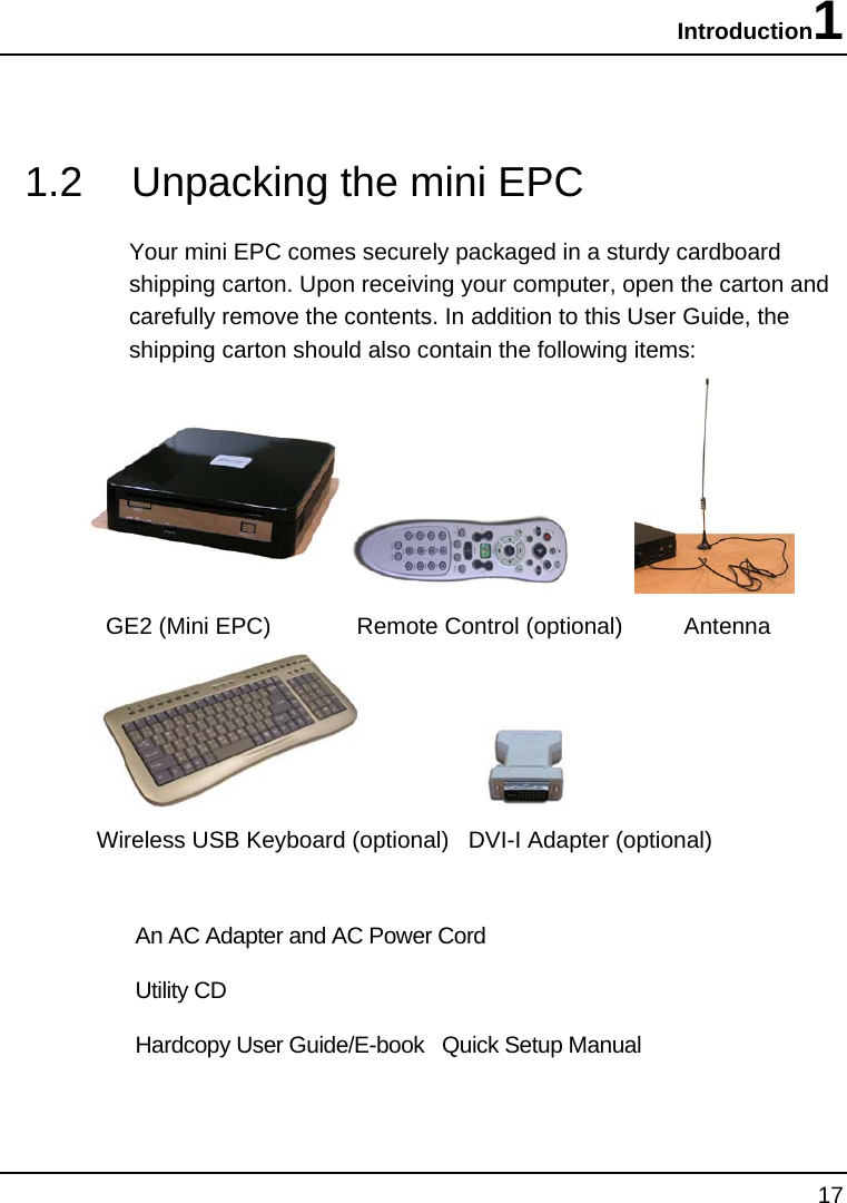
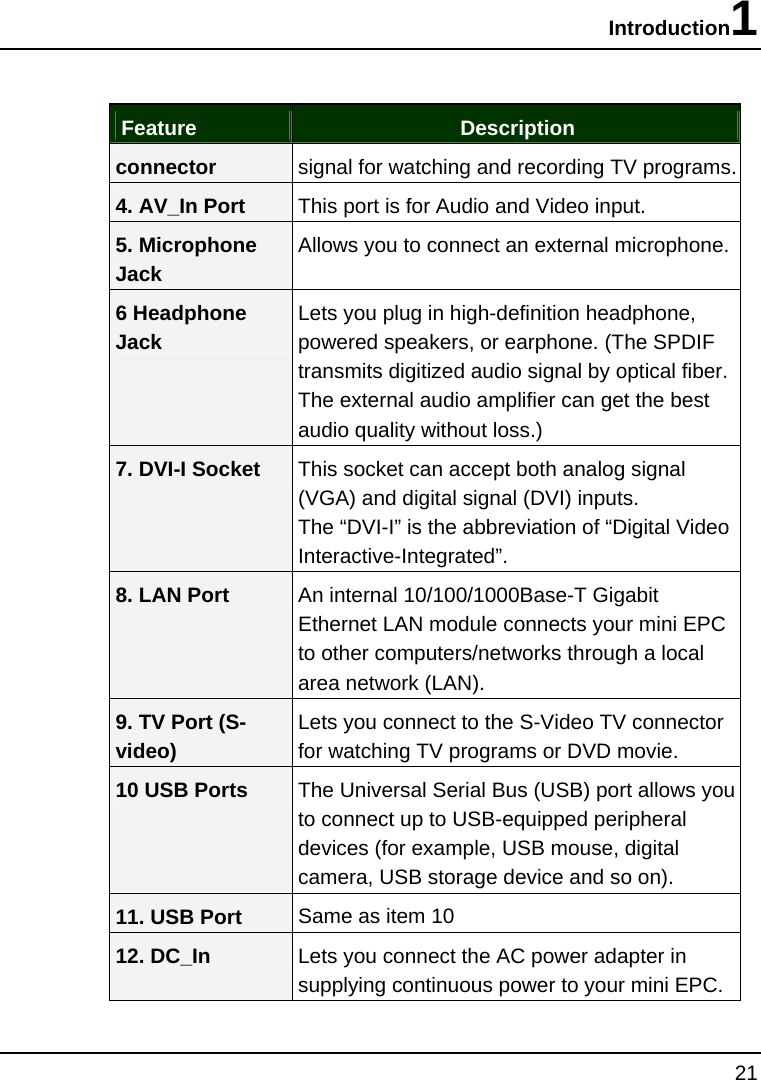
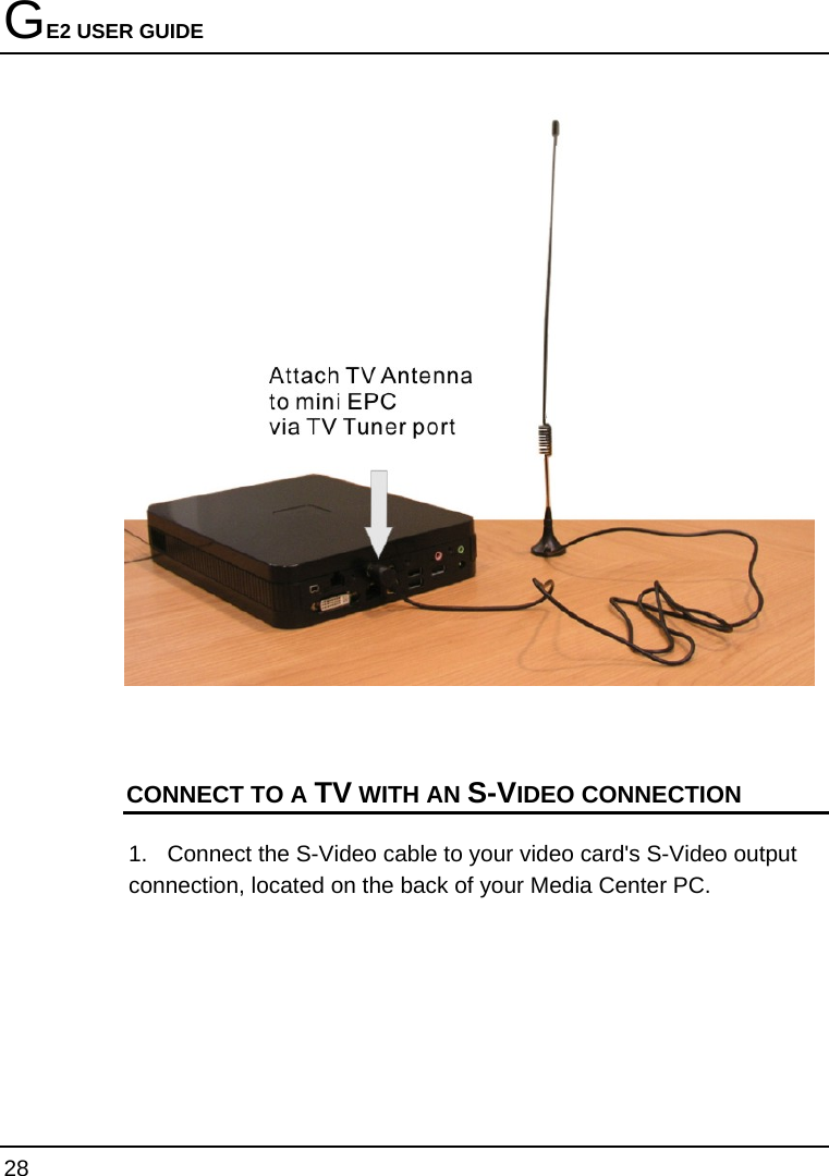
![GE2 USER GUIDE 6 ---Consult the dealer or an experienced radio/TV technician for help. 5.21 Regulatory information / Disclaimers Installation and use of this Wireless LAN device must be in strict accordance with the instructions included in the user documentation provided with the product. Any changes or modifications (including the antennas) made to this device that are not expressly approved by the manufacturer may void the user’s authority to operate the equipment. The manufacturer is not responsible for any radio or television interference caused by unauthorized modification of this device, or the substitution of the connecting cables and equipment other than manufacturer specified. It is the responsibility of the user to correct any interference caused by such unauthorized modification, substitution or attachment. Manufacturer and its authorized resellers or distributors will assume no liability for any damage or violation of government regulations arising from failing to comply with these guidelines. IMPORTANT NOTE (CO-LOCATION) FCC RF Radiation Exposure Statement: This equipment complies with FCC RF radiation exposure limits set forth for an uncontrolled environment. This device and its antenna must not be co-located or operating in conjunction with any other antenna or transmitter. IMPORTANT NOTE (CO-LOCATED EVALUATION PERFORMED) This transmitter has been demonstrated co-located operation compliance requirement with [PRODUCT DESCRIPTION/BRAND/MODEL#]. This transmitter must not be co-located or operating in conjunction with any other antenna or transmitter.](https://usermanual.wiki/First-Computer/GE2L/User-Guide-677138-Page-6.png)
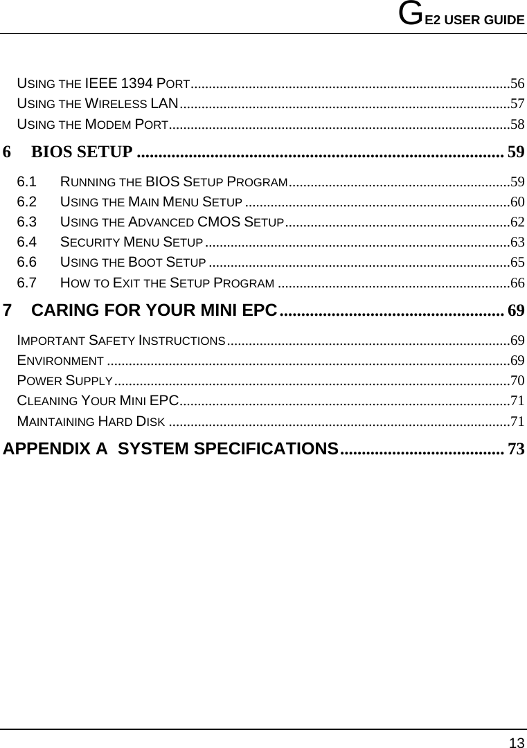
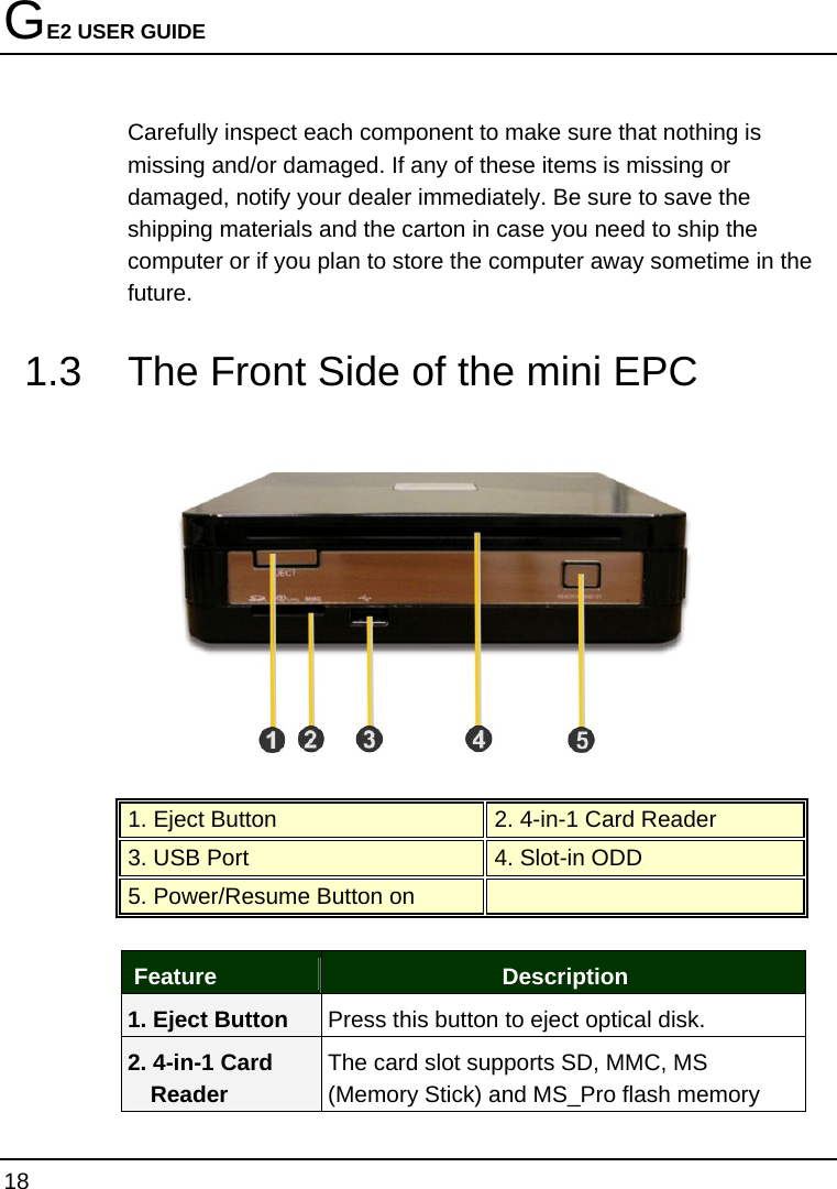
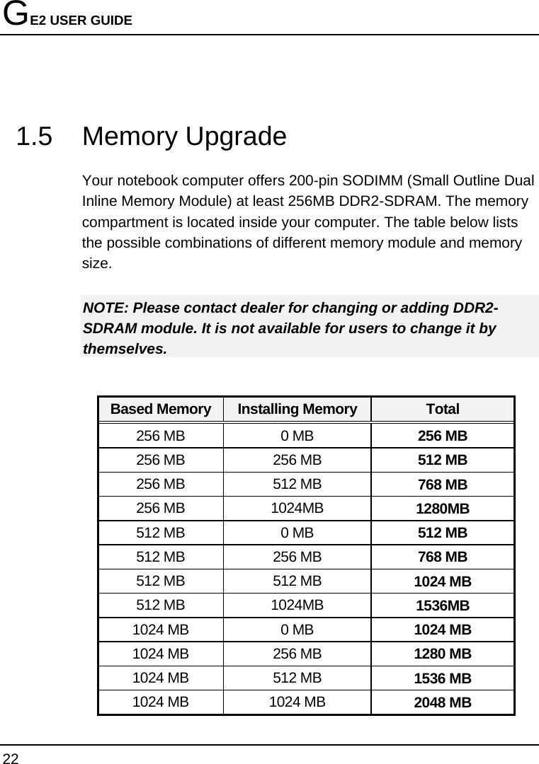


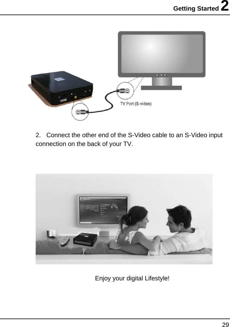

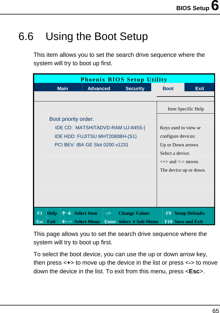
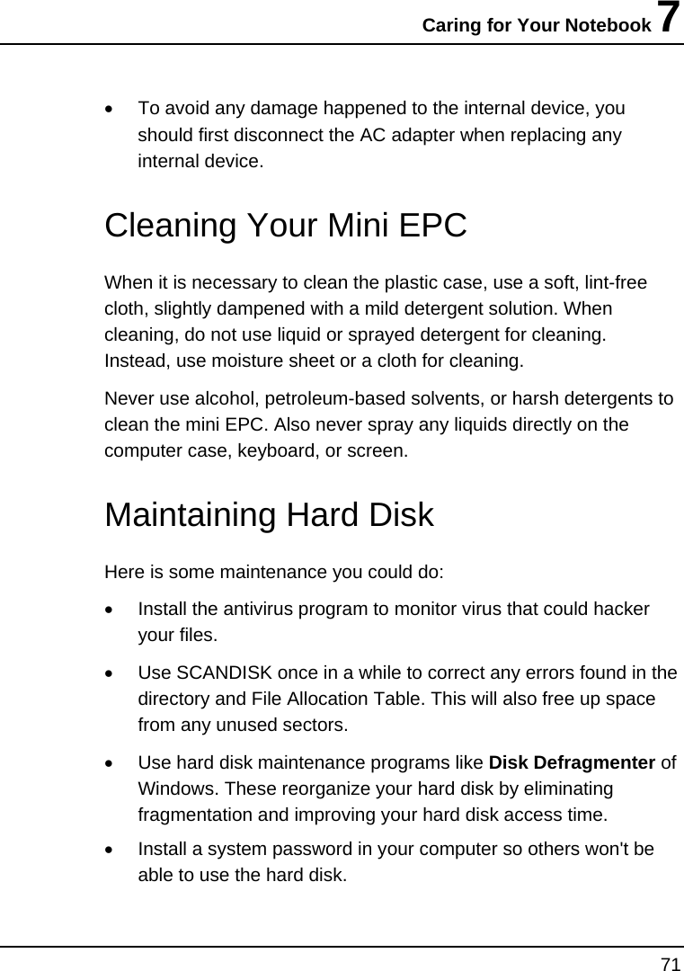
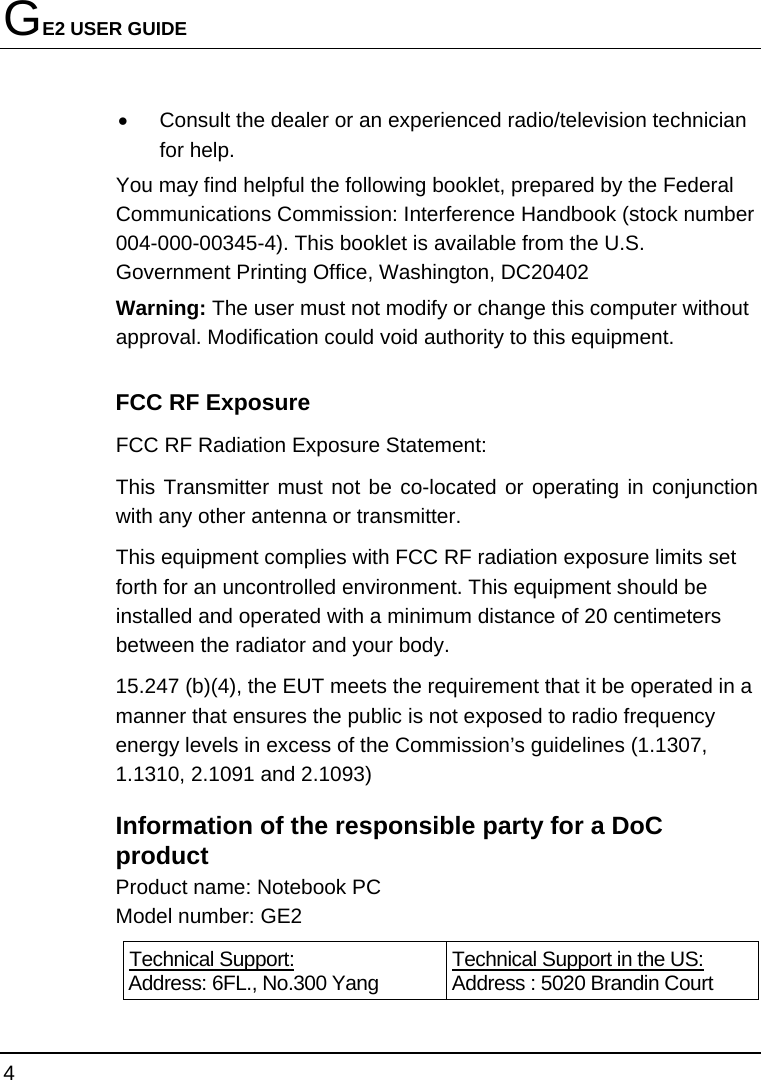
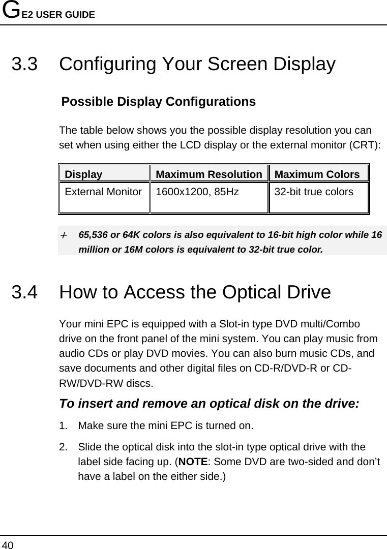
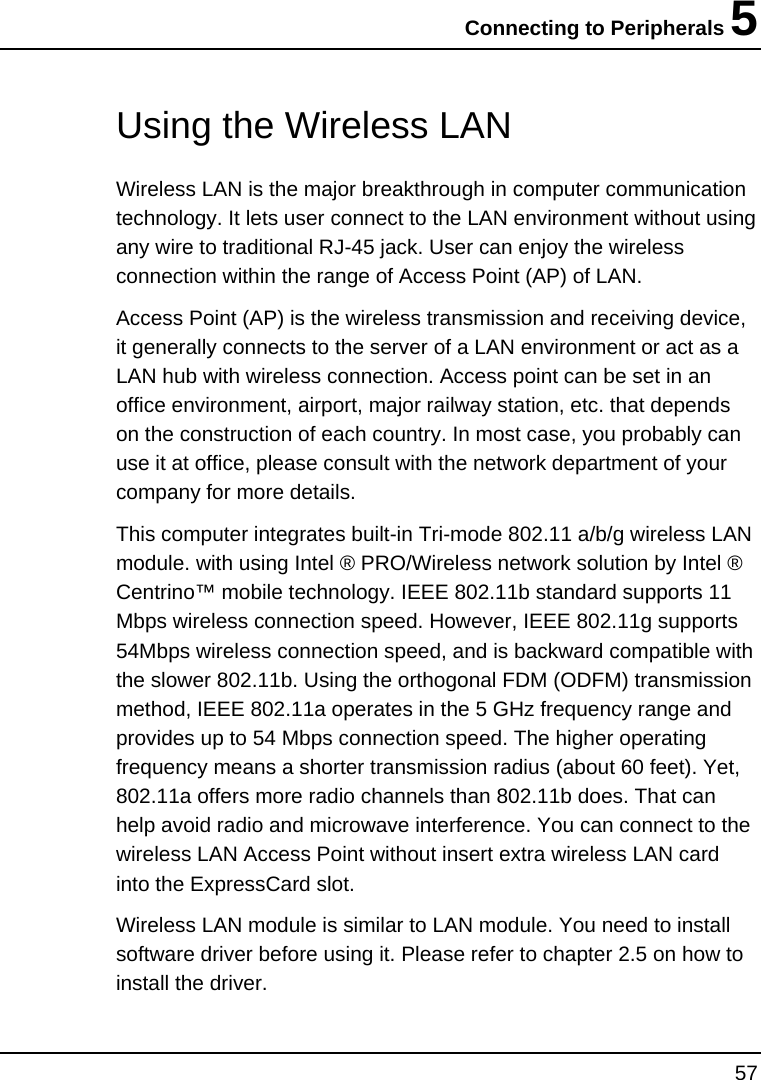
![Using Your Mini EPC 3 39 [The real Wireless USB Keyboard for shipment is still NOT available. This one is for symbol only.] Key numbers: 99Keys (including hot-keys) Battery: AA size Battery x4 Parameters for Remote Control Distance for remote control: within 5m. Angle for remote control: 360 degrees Frequency band for signal transmitted: at 2.4GHz frequency. Standby Mode: System will wait for 5 minutes to activate Standby Mode if there is no any input signal. (During Standby Mode, mouse (pointing device) will be disabled while keyboard function reminds alive. You can touch any key to resume system.](https://usermanual.wiki/First-Computer/GE2L/User-Guide-677138-Page-39.png)
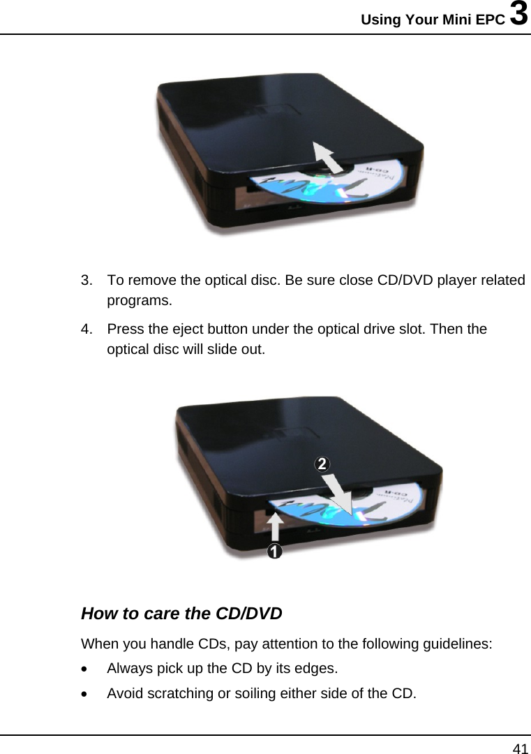
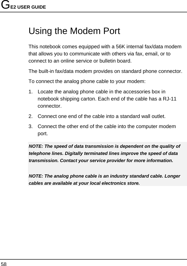
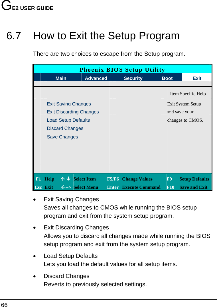
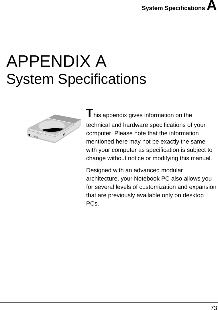
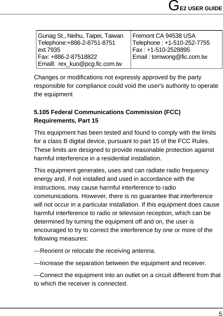
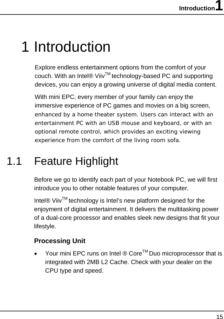
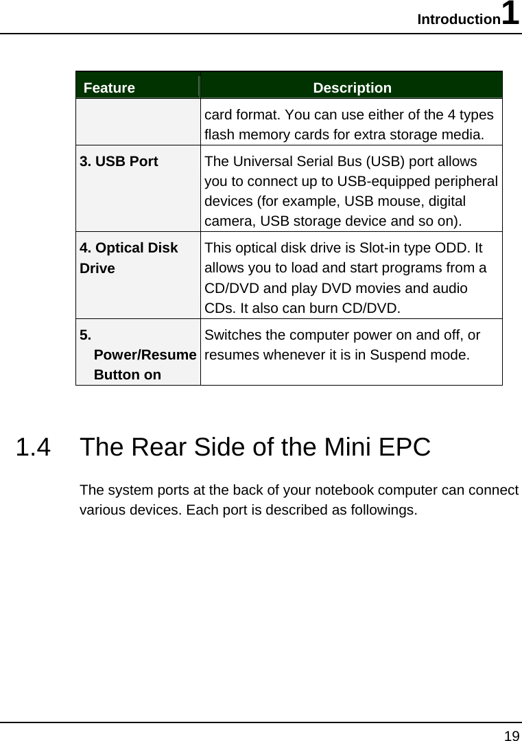
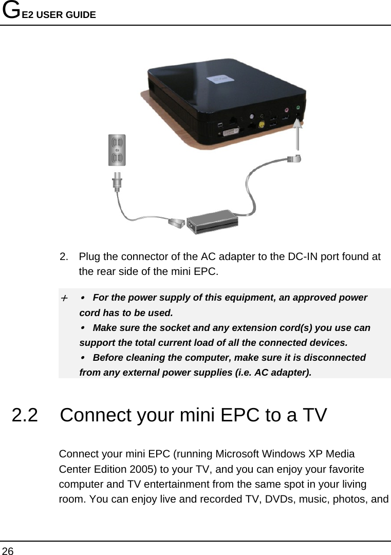
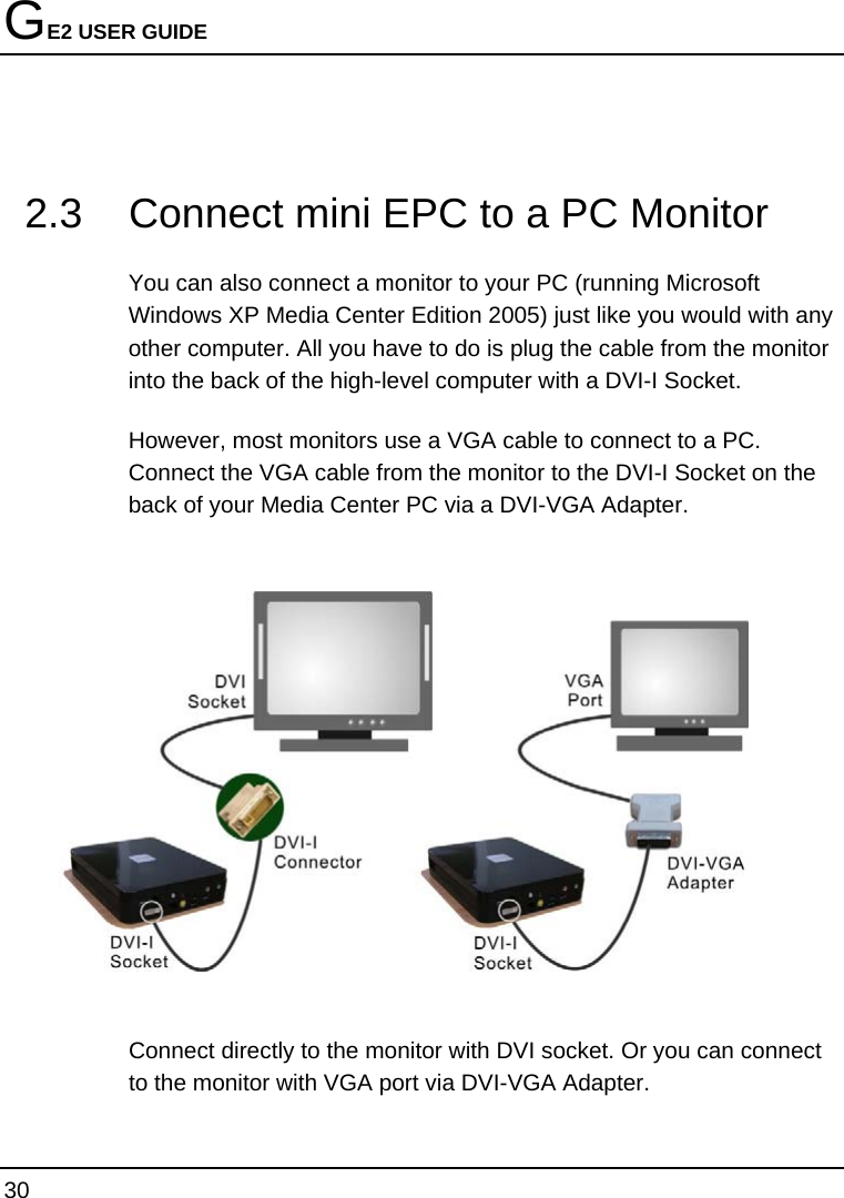
![GE2 USER GUIDE 60 the screen are some brief help descriptions of each item you want to change. To exit the BIOS Setup program, simply press the <Esc> key and select from the Exit menu whether you want to Save changes and exit; Discard Changes and exit. 6.2 Using the Main Menu Setup Phoenix BIOS Setup Utility Main Advanced Security Boot Exit Item Specific Help System Time: [10 :28 :32] <Tab>, <Shift-Tab>, System Date: [03/31/2006] or <Enter> selects field. 4IDE Channel 0 Master [ Installed CD/DVD] 4SATA Port 0 [ 80026MB SATA1] CPU Type: Intel® Pentium® M CPU CPU Speed: 1660 MHz System Memory: 640 KB Extended Memory: 1038336 KB BIOS Version: C.3B-1284-0000 F1 Help Ç È Select Item -/+ Change Values F9 Setup Defaults Esc Exit Å--> Select Menu Enter Select Sub-Menu F10 Save and Exit](https://usermanual.wiki/First-Computer/GE2L/User-Guide-677138-Page-60.png)
![BIOS Setup 6 61 • System Time Allows you to change the system time using the hour: minute: second format of the computer. You can also change the system time from your operating system. • System Date Allows you to set the system date using the month/date/year format. You can also change the system time from your operating system. • IDE Channel 0 Master This field display various parameters for the hard disk drive. If type [Auto] is selected, the system automatically sets these parameters. If type [User] is selected, Cylinders, Heads and Sectors and other value can be edited. • SATA Port 0 This field is for information only as the BIOS automatically detects the optical drive. • CPU Type This field reports the CPU type information detected by the BIOS during Power-On Self-Test (POST). • CPU Speed This field reports the CPU speed information detected by the BIOS during Power-On Self-Test (POST). • System Memory This field reports the amount of base (or conventional) memory found by the BIOS during Power-On Self-Test (POST).](https://usermanual.wiki/First-Computer/GE2L/User-Guide-677138-Page-61.png)
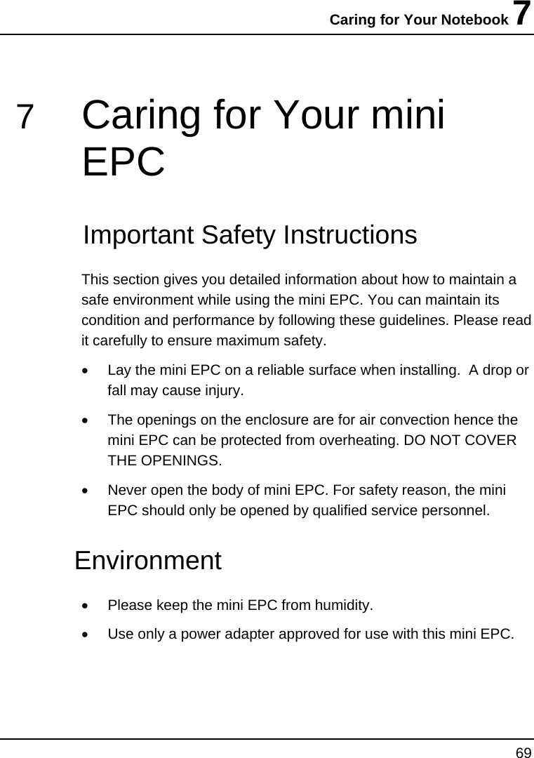
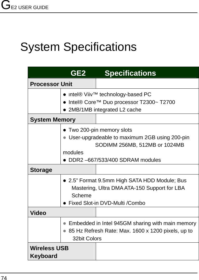
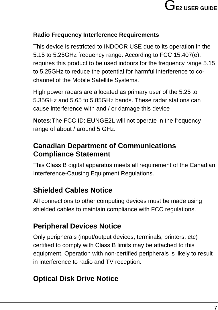
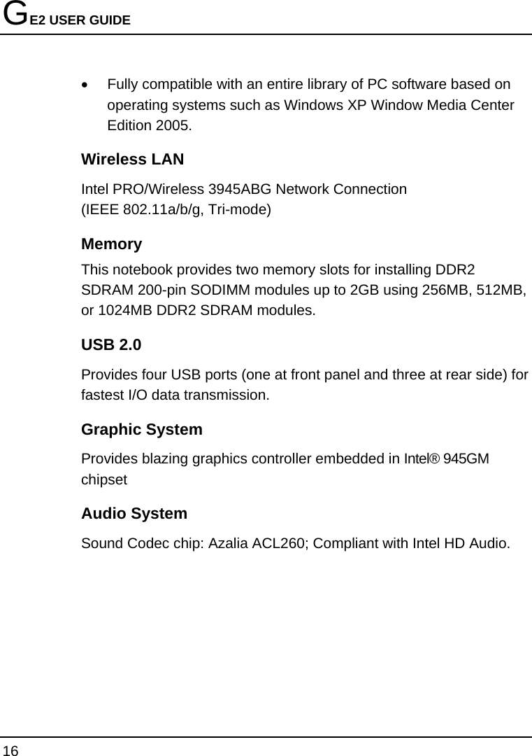
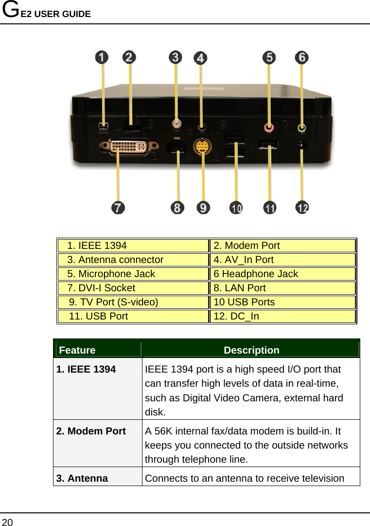
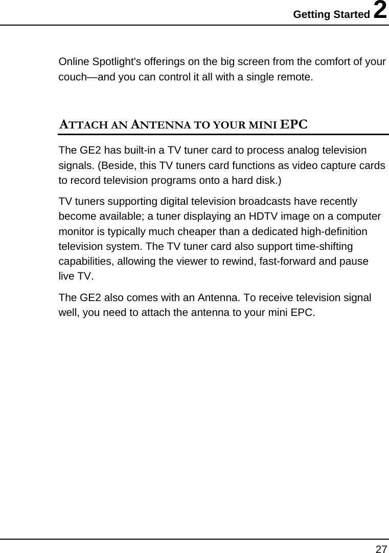
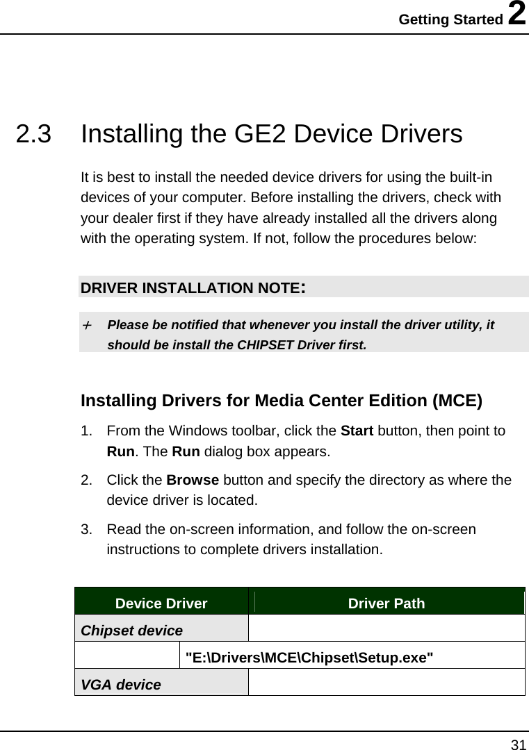
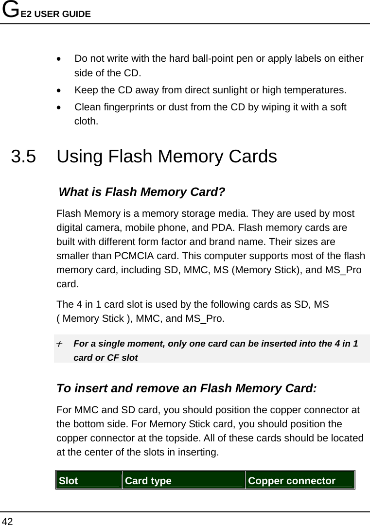
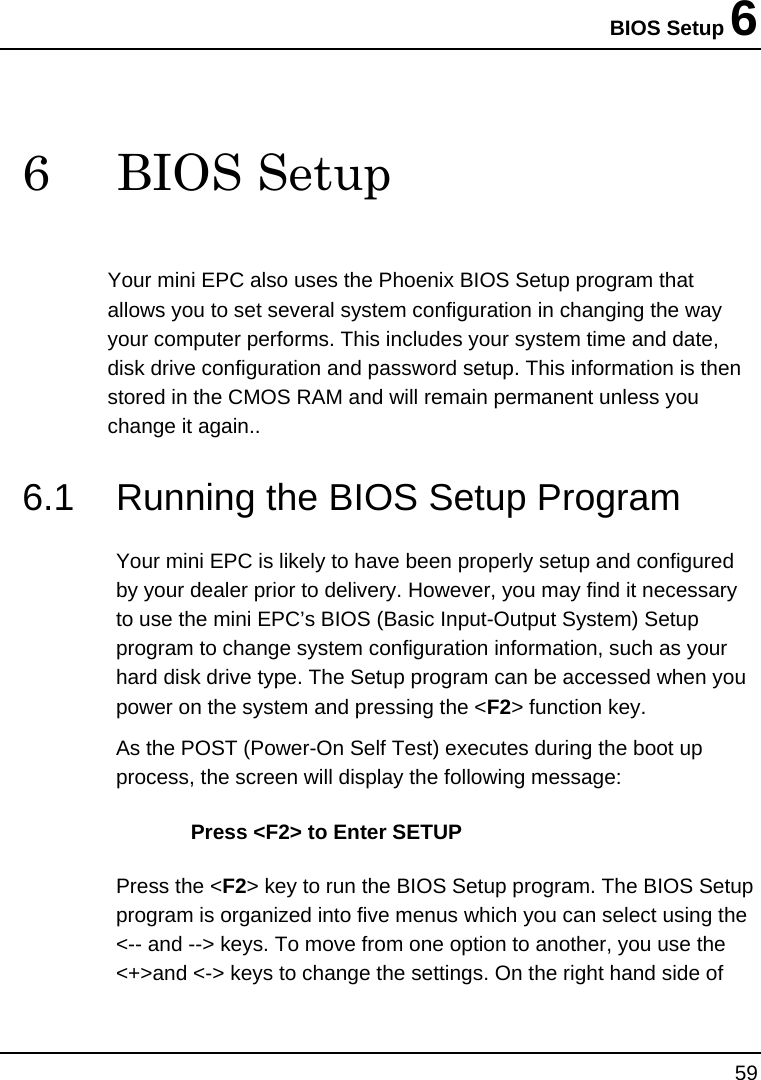
![GE2 USER GUIDE 62 • Extended Memory This field reports the amount of extended memory found by the BIOS during Power-On Self-Test (POST). • BIOS Version This field is for information only as the BIOS displays the BIOS version during the Power-On Self-Test (POST). 6.3 Using the Advanced CMOS Setup Phoenix BIOS Setup Utility Main Advanced Security Boot Exit Item Specific Help Legacy USB Support: [Enabled] Enable support for Boot-time Diagnostic Screen [Disabled] Legacy Universal Serial Extended Memory Testing [None] Bus F1 Help Ç È Select Item -/+ Change Values F9 Setup Defaults Esc Exit Å--> Select Menu Enter Select Sub-Menu F10 Save and Exit • USB Legacy Support Enable or disable the USB Bus support when in connection with USB device. • Disable Logo screen](https://usermanual.wiki/First-Computer/GE2L/User-Guide-677138-Page-62.png)
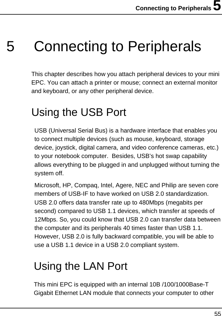
![BIOS Setup 6 63 Select boot screen using options: [Enabled] to display POST screen, or [Disabled] to display Logo screen. 6.4 Security Menu Setup Phoenix BIOS Setup Utility Main Advanced Security Boot Exit Item Specific Help Supervisor Password Is: Clear User Password Is: Clear Supervisor Password controls access to the Set Supervisor Password [Enter] setup utility. Set User Password [Enter] Password on boot [Disabled] Fixed disk boot sector [Normal] F1 Help Ç È Select Item -/+ Change Values F9 Setup Defaults Esc Exit Å--> Select Menu Enter Select Sub-Menu F10 Save and Exit • Supervisor Password Is Set/Clear selections show that the notebook is under controlled by Supervisor Password or not. • User Password Is Set/Clear selections show that the notebook is under controlled by User Password or not.](https://usermanual.wiki/First-Computer/GE2L/User-Guide-677138-Page-63.png)