Fleetwood Group WRS960X Low Power Wireless Response System Controller User Manual CERTIFICATE OF COMPLIANCE
Fleetwood Group Inc Low Power Wireless Response System Controller CERTIFICATE OF COMPLIANCE
users manual

Rhein Tech Laboratories, Inc. Client: Fleetwood Group, Inc.
360 Herndon Parkway Model Name: WRS960X
Suite 1400 Standards: FCC 15.247/IC RSS-210
FCC/IC ID: FBRWRS960X/1859A-WRS960X Herndon, VA 20170
http://www.rheintech.com Report #: 2007182
Page 38 of 46
Appendix I: Manual
Please refer to the following pages.

1
Preliminary Document
USER MANUAL
Reply®
• Base Station, Model WRS960X

Preliminary Document
©Copyright 2007 Fleetwood Group, Inc., Electronics Division. All rights reserved. Licensed software products are
owned by Fleetwood Group, Inc. or its suppliers and are protected by United States copyright laws and international
treaty provisions.
Fleetwood Group, Inc. products are covered by U.S. and foreign patents, issued and pending. Information in this
publication supersedes that in all previously published material. Specifications and pricing are subject to change
without notice.
Printed in the U.S.A.
Fleetwood Group, Inc.
Electronics Division
11832 James St.
Holland, Michigan 49424
www.fleetwoodgroup.com
www.replysystems.com
Sales: 1-800-257-6390
Technical Service: 1-888-GO-REPLY (467-3759)
Reply® is a registered trademark of Fleetwood Group, Inc.
Other trademarks contained herein are the property of their respective holders.
Revision History:
Rev Date Description
A 06/01/07 Original

Preliminary Document
3
Table of Contents
1.0 Reply® Systems ......................................................................................................................... 5
1.1 Introduction....................................................................................................................................... 5
1.2 Applications/Advantages.................................................................................................................. 5
1.3 RF Communication........................................................................................................................... 5
1.4 Technology Leadership, Patent Protection, and Certification...................................................... 5
1.5 Other Fleetwood Group, Inc. Products........................................................................................... 5
2.0 Principles of Operation............................................................................................................ 5
2.1 Placement of the Reply® System ...................................................................................................... 6
3.0 How to Use the Keypad ............................................................................................................ 6
3.1 Initial Setup ....................................................................................................................................... 6
3.2 Softkeys .............................................................................................................................................. 7
3.3 Set Keypad Address.......................................................................................................................... 7
3.4 Set Keypad Channel Number .......................................................................................................... 7
3.5 Changing the Batteries ..................................................................................................................... 7
4.0 How to Use the Base ................................................................................................................ 8
4.1 System Power..................................................................................................................................... 8
4.2 Main Menu......................................................................................................................................... 8
4.3 System Help ....................................................................................................................................... 8
4.4 System Setup Menu........................................................................................................................... 8
4.4.1 Channel Selection...............................................................................................................................................8
4.4.2 Video Output Control.........................................................................................................................................8
4.4.3 Backlight Control................................................................................................................................................8
4.4.4 Keypad Test Screen............................................................................................................................................8
4.4.5 Video System Selection......................................................................................................................................9
4.4.6 Firmware Revision .............................................................................................................................................9
4.4.7 LCD Contrast Control ........................................................................................................................................9
4.5 Loading Predefined Questions......................................................................................................... 9
4.6 Saving Test Results ........................................................................................................................... 9
4.7 Clearing Questions and Test Results............................................................................................... 9
4.8 Voting Predefined Questions.......................................................................................................... 10
4.9 Voting Impromptu Questions ........................................................................................................ 10
4.10 Displaying Test Results................................................................................................................. 10
4.10.1 Graphing Test Results ....................................................................................................................................10
4.10.2 Grid Display Test Results...............................................................................................................................10
5.0 CSV File Data Format........................................................................................................... 11
5.1 Question.csv File Format................................................................................................................ 11
5.2 Results.csv File Format................................................................................................................... 12

Preliminary Document
6.0 Keypad 9XX code Quick Reference Guide.............................................................................13
7.0 Command List.........................................................................................................................14
8.0 How To Return Components..................................................................................................15
9.0 Accessories ..............................................................................................................................16
10.0 Limited Product Warranty....................................................................................................17
11.0 FCC Compliance Information .............................................................................................18
12.0 Technical Specifications.......................................................................................................19
13.0 Troubleshooting Procedures ................................................................................................20
14.0 Index......................................................................................................................................21

Preliminary Document
5
1.0 Reply® Systems
1.1 Introduction
The Einstein base unit is designed to provide users
with a simple method of using Reply® Worldwide
keypads without the need of a PC.
Questions can be asked without a
PC by using the “Impromptu”
feature. An optional USB flash
drive allows users to create pre-
defined questions on a PC and
administer these questions.
Voting results will be stored on
the base with the option of saving
these results to the USB drive for
further interpretation.
1.2 Applications/Advantages
Many meeting and learning
venues require a mechanism for
audience interaction. Moreover,
many seek a method of automating surveys and
grading activities. Reply® meets the need for such an
interactive tool, bringing everyone together and
instantly allowing measurement of interest,
understanding, and involvement.
¾ Audience members can participate from
their seat and personally indicate their opinions,
ideas, and knowledge.
¾ Results of the interaction are immediately
available, and their display offers presenters a
valuable insight into the opinion and comprehension
level of audience members.
¾ System setup is as simple as handing a
Keypad to every participant and optionally
connecting the Base to a video display. No
Base/Keypad wires or cabling are required prior to
use. This allows fast, reliable, safe, and attractive
installation.
1.3 RF Communication
The Keypads communicate with the Base Station
using wireless Radio Frequency (RF) technologies.
The patented proprietary design has been rigorously
tested and optimized for reliability and collection
speed.
1.4 Technology Leadership, Patent Protection,
and Certification
Fleetwood Group, Inc. maintains a leadership
position in wireless development of audience
response solutions. United States Patents 5,093,786,
Re. 35,449 and other patents reflect the commitment
to wireless technology leadership and the unique
position that Fleetwood Group, Inc. brings to the
market. Additional United States and foreign patents
are pending.
Fleetwood Group, Inc. also maintains a commitment
to complying with the United States Federal
Communications Commission and various
foreign regulatory requirements. In
addition to satisfying various FCC
requirements, such as Part 15, Part 68, and
Part 74, many foreign countries have type
approved Fleetwood products. Others are
continuously being added. Please contact
your reseller or Fleetwood Group, Inc. for
more information on certification.
1.5 Other Fleetwood Group, Inc.
Products
Fleetwood Group, Inc. is a manufacturer of
quality electronic products that are sold
through a worldwide reseller network. All Reply®
products are designed and manufactured in Holland,
Michigan.
For more information on these products or our
customization capability, please visit our website at
www.replysystems.com.
2.0 Principles of Operation
This Reply® System uses the latest in 2.4 GHz
wireless technology to turn any meeting into a
dynamic interactive experience for each participant
without having to deal with a nightmare of cables and
connectors.
Fleetwood is unique in the marketplace with its
patented technology to provide a two-way link with
the keypads. This design ensures that no responses
are missed by requiring a keypad to retransmit the
user’s response until it is properly received by the
Base Station. The design also allows the system to
refuse to acknowledge any invalid entries. This is
clearly superior to other technologies using one-way
radio or infrared, which do not provide
acknowledgment to the keypad when its entry is
received and do not have any way of rejecting invalid
entries.
Preliminary Document
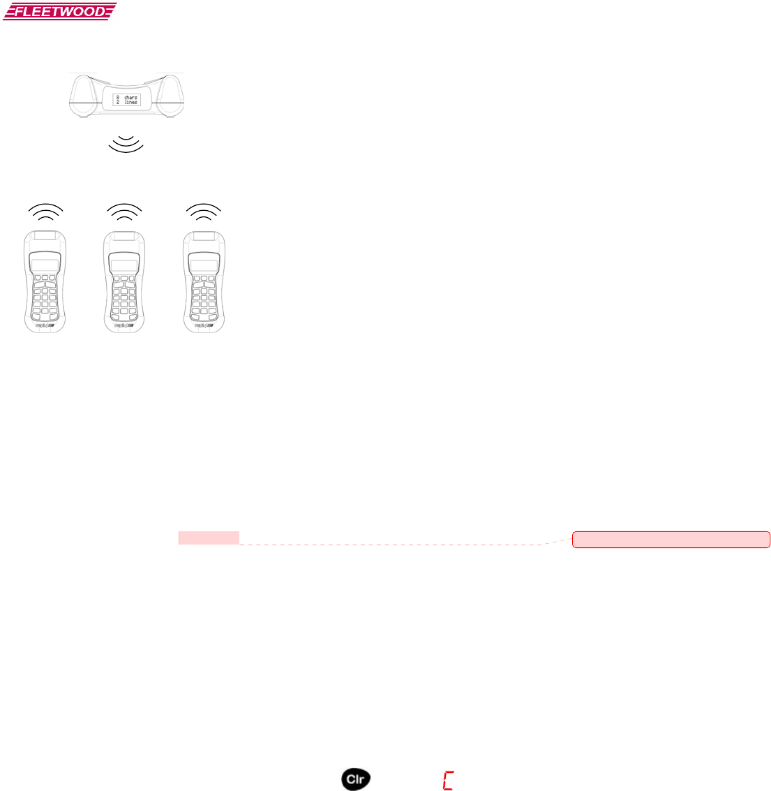
The WRS960X Base Station is the control center for
the system. The Base Station can be set to any of the
15 available channels. A Base Station can process
responses from up to 50 keypads.
A radio frequency packet is continuously sent, while
polling is active, by the base station. Each base
station’s packet can only be heard by keypads that
have been set to the same channel.
2.1 Placement of the Reply® System
The Base Station can be located anywhere in the area
where the keypads are to be used. WRS5200
keypads can operate in a room up to 300’ x 300’ in
size. Despite a robust communication system, walls
and some other 2.4 GHz devices can moderately to
severely limit the WRS960X system’s performance.
If coverage of a larger area is necessary, elevation of
the Base Station or centering in room can usually
improve the reception of the keypad signals.
NOTE: Due to the properties of signals operating at
2.4 GHz, Fleetwood does not recommend placing any
walls between the base station and the keypads. The
material in a wall tends to absorb the RF signal and
slightly reduced performance might be observed.
3.0 How to Use the Keypad
Each keypad is powered by a single chip that
contains both a microcontroller and integrated 2.4
GHz wireless transceiver. The keypad contains a
fully integrated antenna that eliminates the need for
bulky, inconvenient, external antennas
3.1 Initial Setup
After the Base Station is turned on, pass out the
keypads to the meeting participants and demonstrate
how the keypad works. Ask each person to press a
numeric key on his or her keypad and observe what
happens. When a key on the keypad is pressed, a
single digit display will indicate which key was
activated.
The digit keys (1 through 10) are used to enter
numeric responses, including multiple choice
questions (A through E) or yes/no answers, into
keypad memory. The key must be released to allow
the next key press to occur. Entries are transmitted to
and stored on the Reply® WRS960X Base Station.
Data can be offloaded from the base, at later time, via
USB disk. As keys are pressed, the digits are echoed
on the seven-segment display (SSD).
During normal operation, the displayed digit will go
out within 3 seconds. This indicates to the user that
the Base Station has accepted the entry and the
hardware is operational.
If the light blinks and comes back on, this means that
the Base Station addressed the keypad but was not
able to accept the entry. This could mean one of a
few things:
¾ An invalid choice was made. A key masking
function, that rejects entries from certain keys, is
used depending on the question type being
polled. For example, keys #3 – 9 and 0 will be
marked as invalid answers and keys #1 - 2 as
valid answers to a Yes/No question. The
participant should press the “Clear” key and
enter a new valid answer.
Comment [B.H.1]: Is this range correct?
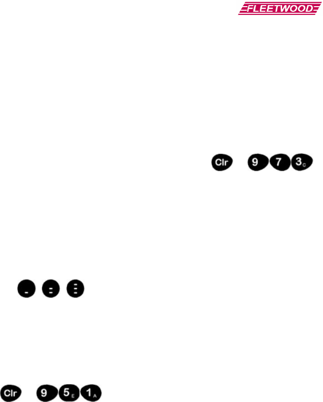
To clear a response, the CLEAR key must be
pressed and released before the Reply®
WRS960X Base Station receives the keypad
transmission. This may take 0.5 second. While
the “Clear” key is depressed, the keypad will
display the letter C on the SSD.
“ ”
Preliminary Document
7
Figure 1-A
¾ The keypad is out of range of the Base Station.
Try moving the keypad closer to the base. An
out of range keypad’s LED indicator will wink
approximately every 2.5 seconds (with 250
keypads polling).
¾ If the LED indicator on one keypad stays on and
never blinks while other keypads are working,
check the address and channel of the keypad. If
everything appears to be set correctly, then the
pad might need factory repair.
There is also a low battery detect circuit built into the
keypad to notify the user when the battery is getting
low and needs replacement. This causes the LED
indicator to flash at a high rate (several times per
second) when the battery is getting low and should be
replaced. There will, however, still be several hours
of usage left in the battery, allowing use of the
keypad until the meeting is completed.
3.2 Softkeys
WRS5200 Softkeys
A new feature for the WRS5200 keypad is the
addition of 3 “Softkeys”. These keys can be used as
3 extra general purpose response buttons for non-
numeric responses.
3.3 Set Keypad Address
+
Model WRS5200 keypads have a mode that allows
the user to change or recall the current keypad
address. There are two methods for accessing this
mode:
¾ Enter code 951 (See Section 6 for how to
enter 9XX codes).
¾ Press and hold “Clr” and press “1”. Then
release both keys. This feature may be
disabled from a previous base command. If
it is disabled, use the 951 code listed above.
Once one of the above actions has been performed,
the two lower horizontal segments will light on the
keypad. At this point, you have 5 seconds to do one
of the following actions:
¾ To recall the current address, press the “*”
key. The address will blink out on the
display (001 – 250).
¾ To set a new address, simply type in the new
3-digit address (i.e. “0”-“0”-“1” = address 1,
and “2”-“5”-“0” = address 250).
If the address was changed, the keypad will use this
new address on the next key press.
3.4 Set Keypad Channel Number
+
The WRS5200 keypads contain a mode that allows
the user to recall or change the current channel.
There are two different methods of accessing this
mode:
¾ Enter code 973 (See Section 6 for how to
enter 9XX codes).
¾ Press and hold “Clr” and press “2”. Then
release both keys. This feature may be
disabled from a previous base command. If
it is disabled, use the 973 code listed above.
Once one of the above actions has been performed,
the two lower horizontal segments will light on the
keypad. At this point, you have 5 seconds to do one
of the following actions:
¾ To recall the current channel, press the “*”
key. The channel will blink out on the
display (01 – 15).
¾ To set a new channel, simply type in the
new 2-digit address (i.e. “0”-“1” = channel
1, and “1”-“5” = channel 15).
If the channel was changed, the keypad will use this
new channel on the next keypress.
3.5 Changing the Batteries
Each keypad is powered from 2 x “AA” batteries.
Fleetwood recommends using alkaline batteries, but
rechargeable NiMH batteries work giving a shorter
life. In order to use rechargeable batteries, a third
party charger must be used since the keypads are not
rechargeable. One fresh set of alkaline batteries can
last for up to 100,000 votes.

Preliminary Document
4.0 How to Use the Base
4.1 System Power
Press the Power key to turn on the WRS960X base.
The base will display a Reply® splash screen and then
default to the Main Menu of the system.
The Power key is also used to turn off the base. Press
and hold the Power key, until the “Powering Down”
message is displayed, to shut down the base.
The base will turn off automatically after 5 minutes,
if no keys are pressed.
4.2 Main Menu
Main Menu is the default screen that appears after the
base is powered up. The Main Menu can also be
accessed directly, from most other screens, by
pressing the “Main” button.
The Main Menu allows access to all utility functions
needed to operate the base. Functionality accessible
from the Main Menu includes: Clearing stored
questions and test result data from the base, opening
predefined question lists, saving test result data to a
USB disk, viewing help screens and accessing the
setup menu.
4.3 System Help
System Help is accessible from a Main Menu softkey
and a direct key on the keypad. The System Help
screens provide information on the functionality of
all keys on the base.
To access System Help press the “Help” softkey on
the Main Menu or the direct Help key located near
the bottom of the base membrane. After pressing the
Help key press any other key to access a short
description of the keys functionality.
4.4 System Setup Menu
System setup is accessed with the “Setup” softkey on
the Main Menu. Functionality accessible from the
System Setup screen includes: channel selection,
video output control, backlight control, keypad test
screen, video output format, firmware revision and
LCD contrast control.
4.4.1 Channel Selection
While in the System Setup Menu select the “Basic”
tab with the softkey left/right arrows. Press the “1”
key to access Channel Selection. The Channel
Selection screen displays the currently selected
channel and allows for the selection of different
channels. The valid channel range is 1-15.
Use the softkey left/right arrows to cycle through the
available channels. Channels are stored in the base
memory and are recalled after a power cycle or a
change of batteries.
4.4.2 Video Output Control
While in the System Setup Menu select the “Basic”
tab with the softkey left/right arrows. Press the “2”
key to access Video Output Control. The Video
Output Control screen enables/disables the output of
a video signal from the base. The video signal can be
displayed on devices that support NTSC and
PAL/SECAM video signals. This includes most
TV’s and video projectors.
To enable Video Output, press the “1” key on the
base. To disable Video Output press the “2” key on
the base. The current video selection will be
highlighted. The Video Output selection is not stored
in the base. Video Output will default to disabled
after a power cycle or a change of batteries.
NOTE: Enabling Video Output significantly
decreases battery life. To conserve batteries only
enable Video Output when necessary.
4.4.3 Backlight Control
While in the System Setup Menu select the “Basic”
tab with the softkey left/right arrows. Press the “3”
key to access Backlight Control. The Backlight
selection screen enables/disables the LCD backlight.
When the backlight is turned on the LCD will be
illuminated for 5 seconds after each keypress.
To enable the Backlight, press the “1” key on the
base. To disable the Backlight, press the “2” key on
the base. The Backlight setting is stored in the base
memory and is recalled after a power cycle or a
change of batteries.
NOTE: Enabling the Backlight option will reduce
battery life.
4.4.4 Keypad Test Screen
While in the System Setup Menu select the
“Diagnostics” tab with the softkey left/right arrows.
Press the “4” key to access Keypad Test Screen. The
Keypad Test Screen allows the viewing of responses
from keypads that are set to the same channel as the
base.
The test grid is setup to display all fifty keypads that
can be used with the system. Keypad responses are
displayed in a grid format with 10 keypad address

Preliminary Document
9
numbers per line. (E.g. Responses for keypad
addressed to 1 will be displayed in the upper left
corner. Responses for keypad addressed to 50 will be
displayed in the lower right corner.)
Keypad responses displayed in reverse text (white
text/black background) indicate a low battery on the
keypad.
4.4.5 Video System Selection
While in the System Setup Menu select the
“Advanced” tab with the softkey left/right arrows.
Press the “5” key to access Video System Selection.
The Video System Selection screen allows selection
of the desired video output type. Two video output
formats are supported: NTSC and PAL/SECAM.
To select NTSC video format, press the “1” key on
the base. To enable PAL/SECAM video format,
press the “2” key on the base. The current video
format selection will be highlighted. The Video
System Selection is stored in the base memory and is
recalled after a power cycle or a change of batteries.
4.4.6 Firmware Revision
While in the System Setup Menu select the
“Advanced” tab with the softkey left/right arrows.
Press the “6” key to access Firmware Revision. The
Firmware Revision screen displays the current
version of firmware running on the base.
4.4.7 LCD Contrast Control
While in the System Setup Menu select the
“Advanced” tab with the softkey left/right arrows.
Press the “7” key to access LCD Contrast Control.
Use the softkey left/right arrows to adjust the contrast
of the LCD display. Pressing the left arrow softkey
turns the contrast down. Pressing the right arrow
softkey turns the contrast up.
4.5 Loading Predefined Questions
The WRS960X base supports the ability to load up to
99 predefined questions. Predefined questions are
stored in a CSV file format. See additional
documentation on creating predefined questions here.
The questions are loaded via a USB flash drive.
Previously loaded questions will be overwritten with
new questions.
To load predefined questions, connect a USB flash
drive containing the Question.csv file. From the
Main Menu, select the “Open” softkey option. A
USB animation will be displayed as the predefined
question file is loaded into the base memory.
If the question file is loaded successfully, the first
question contained in the Question.csv file will be
displayed for polling. If an error occurs while
loading a question file the base will return to the
Main Menu. Loaded questions are stored in base
memory and will be available after a power cycle or a
change of batteries.
WARNING: Do NOT remove the USB flash drive
while the base is loading a question file. Corruption
of data on the USB flash drive may occur if the drive
is removed while being accessed.
4.6 Saving Test Results
The WRS960X base supports the ability to store up
to 99 test results. Test results may be a combination
of predefined question results and impromptu
question results. Both types of questions may be re-
voted up to 10 times. Re-voting a question uses an
additional test result storage space. Test results are
stored in base memory and will be available after a
power cycle or a change of batteries.
To save test results, connect a USB flash drive to the
base. From the Main Menu, select the “Save”
softkey option. A USB animation will be displayed
as the test results file is saved to the USB flash drive.
A confirmation screen will be displayed after test
results are successfully stored to disk.
NOTE: Saving test results can take anywhere from a
couple of seconds to a couple of minutes. The time
depends on the type of USB flash drive used and the
size of the test result file being saved. Test results
may be displayed using this software.
WARNING: Do NOT remove the USB flash drive
while the base is saving test results. Corruption of
data on the USB flash drive may occur if the drive is
removed while being accessed.
4.7 Clearing Questions and Test Results
All predefined questions and test results are stored in
memory on the base. Periodically this data needs to
be cleared. From the Main Menu, select the “New”
softkey option. Press the “1” key to delete all
predefined questions and stored test results from base
memory. Press the “2” key to return to Main Menu
without deleting any data.
WARNING: Make sure test results have been stored
to a USB flash disk before deleting. Test results are
NOT recoverable after they have been deleted from
base memory.
Comment [B.H.3]: Need reference to
Neil’s software application
documentation.
Comment [B.H.2]: Need to reference
Neil’s software application
documentation.

Preliminary Document
4.8 Voting Predefined Questions
There are two ways to access predefined questions.
The first predefined question is automatically
displayed after loading from the USB flash drive.
Predefined questions, previously stored in the base,
can also be accessed with the “Query” key. After
pressing the “Query” key a selection between
impromptu and predefined question types is
displayed. Press the “2” key to access predefined
questions.
Predefined questions display a question number in
the format: Q01.0. The “Q” denotes a predefined
question. The “01” specifies the question number.
The “0” specifies the number of times the question
has been re-voted. The left/right softkey arrows
allow for selection of a specific question. The page
up/down softkey will be displayed for questions that
have more than five possible answers. Press the page
up/down softkey to toggle between possible answers.
To start voting a question, press the “Start” polling
key located at the bottom of the base membrane.
Notice that the question number displayed at the
bottom left of the LCD now shows “#0”. During
polling, keypad vote count is displayed instead of
question number. Keypad vote count keeps track of
how many keypads have responded to the question.
Press the “Stop” polling key when finished voting a
question. Select the next question to vote by pressing
the left/right softkey.
4.9 Voting Impromptu Questions
Impromptu questions allow the presenter to ask a
question “on the fly”. These questions can be voted
at any time and do not have to be prepared before a
meeting. There are nine different types of predefined
questions available. They include the following
types:
1. Multiple Choice (A-E)
2. Multiple Choice (1-5)
3. Yes/No
4. Yes/No/Abstain
5. Yes/No/Don’t Know
6. Strongly Agree – Strongly Disagree (4
point)
7. Strongly Agree – Strongly Disagree (5
point)
8. True/False
9. Softkey Response
Press the “Query” key to display the Impromptu
Question/Previously Defined Question selection
screen. Press the “1” key to select an impromptu
question. The list of question types, corresponding to
the description above, is displayed on the screen.
Use the page up/down key to view all question types.
Select the question type by pressing the associated
numeric key. After selecting question type the Select
Correct Answer screen is displayed. The correct
answer is used when displaying user responses in
graph/grid format and when saving test results to file.
Select the correct answer by pressing the associated
numeric key.
The impromptu question is now displayed and ready
for voting. Notice the question number format: I01.0.
The “I” denotes an impromptu type question. The
“01” specifies the impromptu question number. The
“0” specifies the number of times the question has
been re-voted. Impromptu questions can be re-voted
until exiting the currently selected impromptu
question screen.
4.10 Displaying Test Results
Test results are displayed in the order in which
questions are voted. Test results can be displayed in
both a graph and grid format directly on the base.
The graph format displays the voting results in a bar
graph style format. The grid format displays the
voting results in a 50 block grid. Each block in the
grid represents one keypad.
4.10.1 Graphing Test Results
Graphing test results displays the percentage or count
of votes for each possible answer. Press the “Graph”
key, located on the left side of the base membrane, to
display test results. Test results can be displayed in a
percentage format or an actual count format.
Pressing the “Graph” key toggles the between
displaying a percentage or an actual count. Questions
having more than five possible answers will display
the page up/down softkey. Press the page up/down
softkey to display the rest of the results. Press the
left/right softkeys to display results for each question
voted.
4.10.2 Grid Display Test Results
Grid display of test results displays results in a 50
block grid. The grid is read left to right, top to
bottom. Keypad channels 1-10 are displayed on the
first row with additions groups of 10 channels in
following rows. Keypads that have voted the correct
answer will display a “9”. Keypads that have voted
the incorrect answer will display the numerical value
voted. The correct answer for the question is
displayed at the bottom of the screen. Press the
left/right softkeys to display results for each question
voted.

Preliminary Document
11
5.0 CSV File Data Format
5.1 Question.csv File Format
The first record of the CSV file will always contain the number of total questions that have been pre-defined. It will be in
this format:
<Total Questions>[CR][LF]
Total questions will always be 2 bytes of ASCII defining the number of questions (i.e. “03” means there are three questions
and “99” means there are 99 questions.
Each pre-defined question will be stored in a CSV file called “Question.CSV” in the following format:
<Question Number>,[Question Type (1-9)],[Correct Answer],<Number of Keys
Used>,<Text Line 1>,<Text Line 2>,…,<Text Line 12>[CR][LF]
Where:
Item Fixed Length
(Characters) Description
Question Number 2 Question number for the following data (01-99)
Question Type 1 ASCII value representing the question type (same as impromptu list)
Correct Answer 1 Correct answer (numeric keypress expected). For example, if the correct
answer is “True” for a True/False Question, “1” would be listed as the correct
answer.
Number of Keys Used 2 Used to determine what keys to disable on keypad.
Text Line N 20 ASCII string containing text that will be displayed on line N. Each text line
can be up to 20 characters long. Base will automatically pad lines shorter
than 20 characters with spaces (0x00).

Preliminary Document
5.2 Results.csv File Format
“Results.CSV” will contain all question information as well as all keypad responses. Each question record will be in
the following format:
Each question record will be formatted as follows:
Question Information
<Question Number (Major)>,[Question Number (Minor)],[Times Voted],[Question
Type],<Correct Answer>,<Text Line 1>,<Text Line 2>,…,<Text Line 12>
Keypad Voting Information (continuation of the same record but separated for readability)
<Keypad Address>,<Response Data>,<Status>,<Serial Number>…Repeated for all 50
keypads…[CR][LF]
Where:
Item Fixed Length
(Characters) Description
Question Configuration
Items Fixed Length
(Characters) Description
Question Number
(Major) 2 Question Number (01-99)
Question Number
(Minor) 1 Re-Vote Number (0 = initial vote, 1=first re-vote, 2=second re-vote,
etc). The limit is 9
Question Type 1 ASCII value representing the question type (same as impromptu list)
Correct Answer 1 Correct answer (numeric keypress expected). For example, if the
correct answer is “True” for a True/False Question, “1” would be listed
as the correct answer.
Text Line N 20 Text string for line N. Data must be exactly 20 characters long for each
line of text. Extra space on each line should be padded with spaces
(hex 0x20).
Keypad Vote Items Items below repeated for all 50 keypads
Keypad Address 2 Keypad Address (01-50)
Response Data 1
Status 2 Battery status, and other status options TBD
Serial Number 6 Serial Number of the keypad (000000 – FFFFFF)
Preliminary Document
13
6.0 Keypad 9XX code Quick Reference Guide
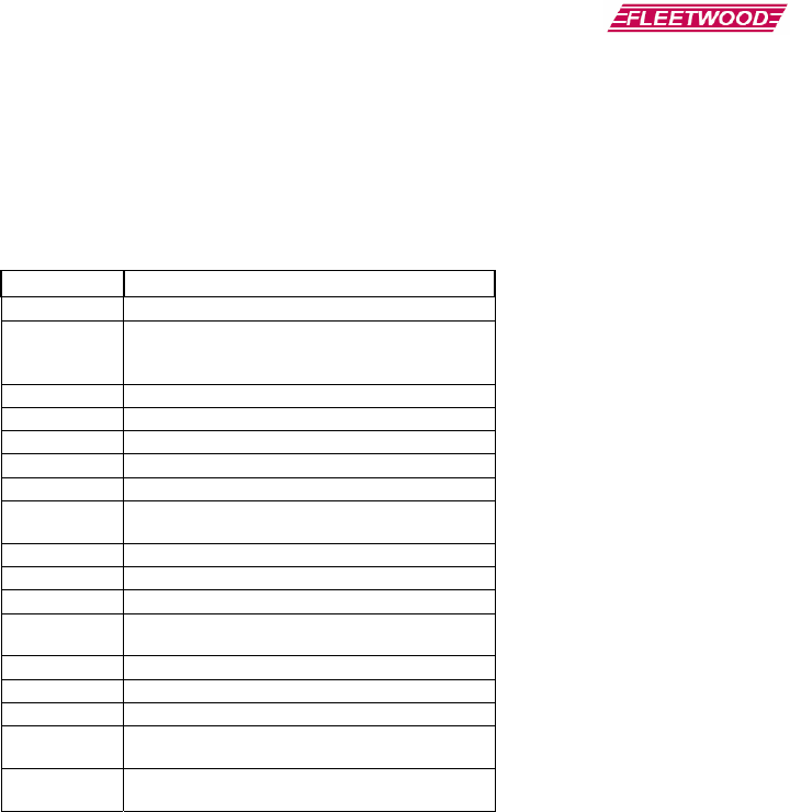
Most of the keypad settings are controlled by a series of 9XX codes, where “XX” represents a two digit number. To
enter a 9XX code, press and hold down the “C” key, type in the 3 digit 9XX code, and release the “C” key.
For example, to enter the code “970”, press and hold the “C” key, type “9”-“7”-“0” and then release all keys. In this
example, the keypad will blink back the firmware revision.
9XX code Description
910 Display the key that was pressed.
911
Display a secure character ("-") instead of the
key that was pressed. The actual key pressed
will still be sent.
920 Disable post acknowledge
921-929 Enable post acknowledge for 1-9 seconds
930 Disable the "*" key.
931 Enable the "*" key.
940 Disable sending low battery message.
941 Enable sending low battery message (A "?" is
sent after each response if the battery is low)
951 Setup the keypad's address.
952 Disable the C-1 and C-2 shortcut keys.
953 Enable the C-1 and C-2 shortcut keys.
960 Display the keypad's 6 digit serial number (in
Hex)
970 Display the keypad's firmware revision
973 Setup the keypad's channel.
980 Reset EEPROM to default settings.
983 Disable key lockout (Any key can be pressed at
any time).
984 Enable key lockout (Only the first key is
accepted until an acknowledge is received).

Preliminary Document
7.0 Command List
This device is designed to be simple and portable. In order to keep operation of this base station simple, not all of
the keypad features on the Reply® Worldwide keypad will be available to be changed. The following table shows
all keypad options and the state that these options will be in when running with an Einstein base station:
Option Status 9XX
Code
Local Echo Always on 910
Asterisk Key Enable Always on 931
Low Battery Notification Always on N/A
Post Acknowledgement Always on 920
Keypad Shortcut Keys Always off N/A
Softkeys Always on N/A
Individual Key Lockout Controlled automatically by
question type N/A
Only Accept First Key Always Off 983

Preliminary Document
15
8.0 How To Return Components
If you encounter a problem that requires sending keypad(s) or base(s) to Fleetwood for service, please enclose a
cover letter with an itemized list of product being returned with a description detailing the problem with each
component. Be as accurate as you can and be sure to include your Name, Return/Billing address and phone
number.
Before shipping the product back to Fleetwood, the owner should contact our Product Service Coordinator at
1-888-GO REPLY (467-3759)
to obtain a Return Material Authorization (RMA) number prior to shipping the product back to the factory.
NOTE: An RMA number MUST be obtained before shipping product back to Fleetwood. Fleetwood will not accept
any product without a RMA Number
For product under Warranty, see section 10.0 “Limited Product Warranty”.
Unless otherwise specified, all parts should be sent to:
Fleetwood Group, Inc.
Electronics Division
Product Service Coordinator
11832 James Street
Holland, MI 49424
Phone Support
To reach Fleetwood’s Technical Support, call 1-888-467-3759.
Fleetwood’s standard hours are Monday through Friday 7:00 AM to 3:30 PM Eastern Standard Time.

Preliminary Document
9.0 Accessories
Call Fleetwood or an authorized dealer for information on available storage/shipping cases, extra cables or power
supply kits.

Preliminary Document
17
10.0 Limited Product Warranty
Fleetwood Group, Inc. warrants its Reply® Cordless Response System components for a period of 24 months from
the date of manufacture for any material or workmanship defect in the product. This warranty does not extend to
batteries or any product component, which has been subjected to misuse, neglect, accidental breakage, improper
installation, use outside of present guidelines, or alteration outside of our factory.
This product uses internal antennas built directly on the printed circuit board. Modifying this antenna in any way
will result in reduced range and will void the warranty. There are no user serviceable parts inside the base or
keypad.
Fleetwood Group, Inc. agrees to remedy, at the factory, any product defect, or at its discretion, replace any
component or part of the product provided the owner complies with the following procedures:
1) The owner is to determine that the problem is not the battery or a faulty or improper connection with the
personal computer or power source.
The owner will contact our Product Service Coordinator at
1-888-GO REPLY (467-3759)
to obtain a Return Material Authorization (RMA) number prior to shipping the product back to the factory.
The owner will send the defective component via prepaid freight to:
Fleetwood Group, Inc.
Electronics Division
Product Service Coordinator
11832 James Street
Holland, MI 49424
2) If the factory determines the defect is due to negligence or oversight on the part of the owner, the owner will be
invoiced for the cost of the repair.

Preliminary Document
11.0 FCC Compliance Information
WRS960X Reply® Base Station and WRS7200 Reply® Keypad
Responsible Party Pertaining to the Declaration of Conformity
Fleetwood Group, Inc.
11832 James Street
Holland, MI 49424
Attn: Product Service Coordinator
Phone: 888-467-3759
This device complies with Part 15 of the FCC Rules and RSS-210 of the Industry Canada Rules. Operation is
subject to the following two conditions: (1) this device may not cause interference and (2) this device must accept
any interference, including interference that may cause undesired operation of the device. The user is cautioned
that changes or modifications to the device that are not approved by the manufacturer could void the user’s
authority to operate the device. Notice
The base and keypad units may be susceptible to Electrostatic Discharge (ESD) and other similar fast transient
events causing system interruption. Should system interruption occur, reset base unit by powering down and
powering up. Push any key on keypads which have powered down.

Preliminary Document
19
12.0 Technical Specifications
Size (LxWxH) (mm) 147.6 x 72.6 x TBD
Weight TBD
Enclosure type Black ABS Plastic
Power Requirements Battery powered, (3) AAA Alkaline Cells
PC Interface USB Flash Drive interface
Connectors/Buttons -USB connector (Type A) for flash drive
-23 key membrane
Display: -132x64 Graphics LCD
-Composite TV Output (NTSC, PAL/SECAM)
Bootloader Main code will be firmware upgradeable
Maximum Keypad Capacity 50
Number of Channels 15
Groups 1 group of 50 keypads per Base ID
Range between keypad and base TBD
Number of pre-defined test
questions 99
Number of times a question can
be repeated and stored to memory Max of 10
Number of impromptu test
questions Max of 99
Answer Length Single digit only.
Battery Life Expectancy TBD
Range Minimum of 100 feet (30.5 m) (with open-air, line-of-sight conditions)
Drop Test Durability Fleetwood EDP100 Type B compliant

Preliminary Document
13.0 Troubleshooting Procedures
DO’s
¾ Position the Base Station in a clear, open location such as the top of a desk. This will provide optimal
performance.
¾ Elevate the Base Station to at least keypad height, or higher if possible for best reception.
¾ Check out the keypads before use. Use a data stream test utility to assure that data is properly flowing to
the PC.
¾ Verify the channel number of each keypad. Make sure it matches the Base Station channel (i.e. Channel #1
pads can only “talk” to a Base Station when it is set to Channel #1).
DON’Ts
¾ Avoid placing the Base Station on large, metal areas such as a TV cart. The metal could cause some RF
performance deterioration.
¾ Never position the Base Station inside or near a metal enclosure.
¾ Avoid positioning the keypad on a metal surface during operation as this may cause the RF performance to
deteriorate.
¾ Never have two Base Stations with the same channel turned “on” at the same time.
¾ Never have two keypads with the same ID number assigned to avoid overwriting keypad responses.
¾ Never use a keypad that has a rapidly flashing display. This indicates the battery is low and must be
replaced.
Caution: Use of the system in an outdoor location or different indoor environments can significantly alter the range
of the keypads.

Preliminary Document
21
14.0 Index
A
Accessories, 14
Answer Types, 11
D
Dynamic Mode System, 10
E
Ethernet, 7
F
Fleetwood products, 5
I
Interface, 14
K
Keypad Backlight, 13
Keypad Menu, 8
Keypad Serial Number, 8
Keypad, basic operation, 7
O
Operating Modes, 9
P
Patent information, 5
Prompting, 12
Q
Question Answers, 12
R
Return Parts, 14
RF communication, 5
S
Service, ii, 14, 15
Software, 14
Static Mode System, 10
System Operation, 9
System Operation Mode
Dynamic, 10
Static, 10
T
Technical Specifications, 17
Troubleshooting, 17
U
Universal Serial Bus (USB), 6
W
Warranty, 15