Flextronics Canada Design Services 10I Wireless Access Point User Manual
Flextronics Canada Design Services Inc. Wireless Access Point Users Manual
Users Manual

P/N 9034671
Enterasys® Wireless
Access Points
Installation Guide
WS-AP3710i
WS-AP3710e
WS-AP3725i
WS-AP3725e
DRAFT
DRAFT

i
Notice
Enterasys Networks reserves the right to make changes in specifications and other information contained in this document and
its web site without prior notice. The reader should in all cases consult Enterasys Networks to determine whether any such
changes have been made.
The hardware, firmware, or software described in this document is subject to change without notice.
IN NO EVENT SHALL ENTERASYS NETWORKS BE LIABLE FOR ANY INCIDENTAL, INDIRECT, SPECIAL, OR
CONSEQUENTIAL DAMAGES WHATSOEVER (INCLUDING BUT NOT LIMITED TO LOST PROFITS) ARISING OUT OF
OR RELATED TO THIS DOCUMENT, WEB SITE, OR THE INFORMATION CONTAINED IN THEM, EVEN IF
ENTERASYS NETWORKS HAS BEEN ADVISED OF, KNEW OF, OR SHOULD HAVE KNOWN OF, THE POSSIBILITY OF
SUCH DAMAGES.
Enterasys Networks, Inc.
50 Minuteman Road
Andover, MA 01810
2012 Enterasys Networks, Inc. All rights reserved.
Part Number: 9034671 October 2012
ENTERASYS, ENTERASYS NETWORKS, ENTERASYS SECURE NETWORKS, NETSIGHT, ENTERASYS NETSIGHT, and any
logos associated therewith, are trademarks or registered trademarks of Enterasys Networks, Inc., in the United States and/or
other countries. For a complete list of Enterasys trademarks, see http://www.enterasys.com/company/trademarks.aspx.
All other product names mentioned in this manual may be trademarks or registered trademarks of their respective companies.
Documentation URL:https://extranet.enterasys.com/downloads/
Electrical Hazard: Only qualified personnel should perform installation procedures.
Riesgo Electrico: Solamente personal calificado debe realizar procedimientos de instalacion.
Elektrischer Gefahrenhinweis: Installationen sollten nur durch ausgebildetes und qualifiziertes Personal
vorgenommen werden.
DRAFT

ii
Hazardous Substances
This product complies with the requirements of European Directive, 2002/95/EC, Restriction of Hazardous Substances (RoHS)
in Electrical and Electronic Equipment.
European Waste Electrical and Electronic Equipment (WEEE) Notice
In accordance with Directive 2002/96/EC of the European Parliament on waste electrical and electronic equipment (WEEE):
1. The symbol above indicates that separate collection of electrical and electronic equipment is required and that this product
was placed on the European market after August 13, 2005, the date of enforcement for Directive 2002/96/EC.
2. When this product has reached the end of its serviceable life, it cannot be disposed of as unsorted municipal waste. It must
be collected and treated separately.
3. It has been determined by the European Parliament that there are potential negative effects on the environment and human
health as a result of the presence of hazardous substances in electrical and electronic equipment.
4. It is the users’ responsibility to utilize the available collection system to ensure WEEE is properly treated.
For information about the available collection system, please contact Enterasys Customer Support at +353 61 705500
(Ireland).
DRAFT

iii
ѻѻક䇈ᯢк䰘ӊ
Supplement to Product Instructions
᳝↦᳝ᆇ⠽䋼ܗ㋴(Hazardous Substance)
䚼ӊৡ⿄
(Parts) 䪙
3E
∲
+J
䬝
&G
݁Ӌ䫀
&U
⒈㘨㣃
3%%
⒈Ѡ㣃䝮
3%'(
䞥ሲ䚼ӊ
(Metal Parts)
hƻ ƻ ƻ ƻ ƻ
⬉䏃ഫ
(Circuit Modules)
hƻ ƻ ƻ ƻ ƻ
⬉㓚ঞ⬉㓚㒘ӊ
(Cables & Cable Assemblies)
hƻ ƻ ƻ ƻ ƻ
ล᭭㘮ড়⠽䚼ӊ
(Plastic and Polymeric parts)
ƻƻ ƻ ƻ ƻ ƻ
⬉䏃ᓔ݇
(Circuit Breakers)
ƻƻ ƻ ƻ ƻ ƻ
ƻ˖ 㸼⼎䆹᳝↦᳝ᆇ⠽䋼䆹䚼ӊ᠔᳝ഛ䋼ᴤ᭭Ёⱘ䞣ഛ SJ/T 11363-2006 ᷛޚ㾘ᅮⱘ䰤䞣㽕∖ҹϟDŽ
Indicates that the concentration of the hazardous substance in all homogeneous materials in the parts is
below the relevant threshold of the SJ/T 11363-2006 standard.
h˖ 㸼⼎䆹᳝↦᳝ᆇ⠽䋼㟇ᇥ䆹䚼ӊⱘᶤϔഛ䋼ᴤ᭭Ёⱘ䞣䍙ߎSJ/T 11363-2006 ᷛޚ㾘ᅮⱘ䰤䞣㽕∖DŽ
Indicates that the concentration of the hazardous substance of at least one of all homogeneous
materials in the parts is above the relevant threshold of the SJ/T 11363-2006 standard.
ᇍ䫔ଂП᮹ⱘ᠔ଂѻકᴀ㸼ᰒ⼎
߃߯կᑨ䫒ⱘ⬉ᄤֵᙃѻકৃ㛑ࣙ䖭ѯ⠽䋼DŽ⊼ᛣ᠔ଂѻકЁৃ㛑Ӯгৃ㛑ϡӮ᳝᠔᳝᠔߫ⱘ䚼ӊDŽ
This table shows where these substances may be found in the supply chain of Enterasys electronic
information products, as of the date of sale of the enclosed product. Note that some of the component types
listed above may or may not be a part of the enclosed product.
䰸䴲⡍߿ⱘᷛ⊼ℸᷛᖫЎ䩜ᇍ᠔⍝ঞѻકⱘ⦃ֱՓ⫼ᳳᷛᖫᶤѯ䳊䚼ӊӮ
᳝ϔϾϡৠⱘ⦃ֱՓ⫼ᳳ՟བ⬉∴ऩܗഫ䌈݊ѻકϞ
ℸ⦃ֱՓ⫼ᳳ䰤া䗖⫼ѢѻકᰃѻકݠЁ᠔㾘ᅮⱘᴵӊϟᎹ
The Environmentally Friendly Use Period (EFUP) for all enclosed products and their parts
are per the symbol shown here, unless otherwise marked. Certain parts may have a
different EFUP (for example, battery modules) and so are marked to reflect such. The
Environmentally Friendly Use Period is valid only when the product is operated under the
conditions defined in the product manual.
DRAFT
iv
Enterasys Networks, Inc. Firmware License Agreement
BEFORE OPENING OR UTILIZING THE ENCLOSED PRODUCT,
CAREFULLY READ THIS LICENSE AGREEMENT.
This document is an agreement (“Agreement”) between the end user (“You”) and Enterasys Networks, Inc., on behalf of itself
and its Affiliates (as hereinafter defined) (“Enterasys”) that sets forth Your rights and obligations with respect to the Enterasys
software program/firmware (including any accompanying documentation, hardware or media) (“Program”) in the package
and prevails over any additional, conflicting or inconsistent terms and conditions appearing on any purchase order or other
document submitted by You. “Affiliate” means any person, partnership, corporation, limited liability company, other form of
enterprise that directly or indirectly through one or more intermediaries, controls, or is controlled by, or is under common
control with the party specified. This Agreement constitutes the entire understanding between the parties, with respect to the
subject matter of this Agreement. The Program may be contained in firmware, chips or other media.
BY INSTALLING OR OTHERWISE USING THE PROGRAM, YOU REPRESENT THAT YOU ARE AUTHORIZED TO ACCEPT
THESE TERMS ON BEHALF OF THE END USER (IF THE END USER IS AN ENTITY ON WHOSE BEHALF YOU ARE
AUTHORIZED TO ACT, “YOU” AND “YOUR” SHALL BE DEEMED TO REFER TO SUCH ENTITY) AND THAT YOU
AGREE THAT YOU ARE BOUND BY THE TERMS OF THIS AGREEMENT, WHICH INCLUDES, AMONG OTHER
PROVISIONS, THE LICENSE, THE DISCLAIMER OF WARRANTY AND THE LIMITATION OF LIABILITY. IF YOU DO NOT
AGREE TO THE TERMS OF THIS AGREEMENT OR ARE NOT AUTHORIZED TO ENTER INTO THIS AGREEMENT,
ENTERASYS IS UNWILLING TO LICENSE THE PROGRAM TO YOU AND YOU AGREE TO RETURN THE UNOPENED
PRODUCT TO ENTERASYS OR YOUR DEALER, IF ANY, WITHIN TEN (10) DAYS FOLLOWING THE DATE OF RECEIPT
FOR A FULL REFUND.
IF YOU HAVE ANY QUESTIONS ABOUT THIS AGREEMENT, CONTACT ENTERASYS NETWORKS, LEGAL
DEPARTMENT AT (978) 684-1000.
You and Enterasys agree as follows:
1. LICENSE. You have the non-exclusive and non-transferable right to use only the one (1) copy of the Program provided in
this package subject to the terms and conditions of this Agreement.
2. RESTRICTIONS. Except as otherwise authorized in writing by Enterasys, You may not, nor may You permit any third
party to:
(a) Reverse engineer, decompile, disassemble or modify the Program, in whole or in part, including for reasons of error
correction or interoperability, except to the extent expressly permitted by applicable law and to the extent the parties
shall not be permitted by that applicable law, such rights are expressly excluded. Information necessary to achieve
interoperability or correct errors is available from Enterasys upon request and upon payment of Enterasys’ applicable
fee.
(b) Incorporate the Program in whole or in part, in any other product or create derivative works based on the Program, in
whole or in part.
(c) Publish, disclose, copy reproduce or transmit the Program, in whole or in part.
(d) Assign, sell, license, sublicense, rent, lease, encumber by way of security interest, pledge or otherwise transfer the
Program, in whole or in part.
(e) Remove any copyright, trademark, proprietary rights, disclaimer or warning notice included on or embedded in any
part of the Program.
3. APPLICABLE LAW. This Agreement shall be interpreted and governed under the laws and in the state and federal courts
of the Commonwealth of Massachusetts without regard to its conflicts of laws provisions. You accept the personal jurisdiction
and venue of the Commonwealth of Massachusetts courts. None of the 1980 United Nations Convention on the Limitation Period
in the International Sale of Goods, and the Uniform Computer Information Transactions Act shall apply to this Agreement.
DRAFT
v
4. EXPORT RESTRICTIONS. You understand that Enterasys and its Affiliates are subject to regulation by agencies of the
U.S. Government, including the U.S. Department of Commerce, which prohibit export or diversion of certain technical products
to certain countries, unless a license to export the product is obtained from the U.S. Government or an exception from obtaining
such license may be relied upon by the exporting party.
If the Program is exported from the United States pursuant to the License Exception CIV under the U.S. Export
Administration Regulations, You agree that You are a civil end user of the Program and agree that You will use the Program for
civil end uses only and not for military purposes.
If the Program is exported from the United States pursuant to the License Exception TSR under the U.S. Export
Administration Regulations, in addition to the restriction on transfer set forth in Section 1 or 2 of this Agreement, You agree not
to (i) reexport or release the Program, the source code for the Program or technology to a national of a country in Country
Groups D:1 or E:2 (Albania, Armenia, Azerbaijan, Belarus, Cambodia, Cuba, Georgia, Iraq, Kazakhstan, Laos, Libya, Macau,
Moldova, Mongolia, North Korea, the People’s Republic of China, Russia, Tajikistan, Turkmenistan, Ukraine, Uzbekistan,
Vietnam, or such other countries as may be designated by the United States Government), (ii) export to Country Groups D:1 or
E:2 (as defined herein) the direct product of the Program or the technology, if such foreign produced direct product is subject to
national security controls as identified on the U.S. Commerce Control List, or (iii) if the direct product of the technology is a
complete plant or any major component of a plant, export to Country Groups D:1 or E:2 the direct product of the plant or a
major component thereof, if such foreign produced direct product is subject to national security controls as identified on the
U.S. Commerce Control List or is subject to State Department controls under the U.S. Munitions List.
5. UNITED STATES GOVERNMENT RESTRICTED RIGHTS. The enclosed Program (i) was developed solely at private
expense; (ii) contains “restricted computer software” submitted with restricted rights in accordance with section 52.227-19 (a)
through (d) of the Commercial Computer Software-Restricted Rights Clause and its successors, and (iii) in all respects is
proprietary data belonging to Enterasys and/or its suppliers. For Department of Defense units, the Program is considered
commercial computer software in accordance with DFARS section 227.7202-3 and its successors, and use, duplication, or
disclosure by the U.S. Government is subject to restrictions set forth herein.
6. DISCLAIMER OF WARRANTY. EXCEPT FOR THOSE WARRANTIES EXPRESSLY PROVIDED TO YOU IN WRITING
BY ENTERASYS, ENTERASYS DISCLAIMS ALL WARRANTIES, EITHER EXPRESS OR IMPLIED, INCLUDING BUT NOT
LIMITED TO IMPLIED WARRANTIES OF MERCHANTABILITY, SATISFACTORY QUALITY, FITNESS FOR A PARTICULAR
PURPOSE, TITLE AND NON-INFRINGEMENT WITH RESPECT TO THE PROGRAM. IF IMPLIED WARRANTIES MAY NOT
BE DISCLAIMED BY APPLICABLE LAW, THEN ANY IMPLIED WARRANTIES ARE LIMITED IN DURATION TO THIRTY
(30) DAYS AFTER DELIVERY OF THE PROGRAM TO YOU.
7. LIMITATION OF LIABILITY. IN NO EVENT SHALL ENTERASYS OR ITS SUPPLIERS BE LIABLE FOR ANY
DAMAGES WHATSOEVER (INCLUDING, WITHOUT LIMITATION, DAMAGES FOR LOSS OF BUSINESS, PROFITS,
BUSINESS INTERRUPTION, LOSS OF BUSINESS INFORMATION, SPECIAL, INCIDENTAL, CONSEQUENTIAL, OR
RELIANCE DAMAGES, OR OTHER LOSS) ARISING OUT OF THE USE OR INABILITY TO USE THE PROGRAM, EVEN IF
ENTERASYS HAS BEEN ADVISED OF THE POSSIBILITY OF SUCH DAMAGES. THIS FOREGOING LIMITATION SHALL
APPLY REGARDLESS OF THE CAUSE OF ACTION UNDER WHICH DAMAGES ARE SOUGHT.
THE CUMULATIVE LIABILITY OF ENTERASYS TO YOU FOR ALL CLAIMS RELATING TO THE PROGRAM, IN
CONTRACT, TORT OR OTHERWISE, SHALL NOT EXCEED THE TOTAL AMOUNT OF FEES PAID TO ENTERASYS BY
YOU FOR THE RIGHTS GRANTED HEREIN.
8. AUDIT RIGHTS. You hereby acknowledge that the intellectual property rights associated with the Program are of critical
value to Enterasys, and, accordingly, You hereby agree to maintain complete books, records and accounts showing (i) license
fees due and paid, and (ii) the use, copying and deployment of the Program. You also grant to Enterasys and its authorized
representatives, upon reasonable notice, the right to audit and examine during Your normal business hours, Your books, records,
accounts and hardware devices upon which the Program may be deployed to verify compliance with this Agreement, including
the verification of the license fees due and paid Enterasys and the use, copying and deployment of the Program. Enterasys’ right
of examination shall be exercised reasonably, in good faith and in a manner calculated to not unreasonably interfere with Your
business. In the event such audit discovers non-compliance with this Agreement, including copies of the Program made, used
or deployed in breach of this Agreement, You shall promptly pay to Enterasys the appropriate license fees. Enterasys reserves
the right, to be exercised in its sole discretion and without prior notice, to terminate this license, effective immediately, for failure
to comply with this Agreement. Upon any such termination, You shall immediately cease all use of the Program and shall return
to Enterasys the Program and all copies of the Program.
9. OWNERSHIP. This is a license agreement and not an agreement for sale. You acknowledge and agree that the Program
constitutes trade secrets and/or copyrighted material of Enterasys and/or its suppliers. You agree to implement reasonable
security measures to protect such trade secrets and copyrighted material. All right, title and interest in and to the Program shall
remain with Enterasys and/or its suppliers. All rights not specifically granted to You shall be reserved to Enterasys.
DRAFT
vi
10. ENFORCEMENT. You acknowledge and agree that any breach of Sections 2, 4, or 9 of this Agreement by You may cause
Enterasys irreparable damage for which recovery of money damages would be inadequate, and that Enterasys may be entitled
to seek timely injunctive relief to protect Enterasys’ rights under this Agreement in addition to any and all remedies available at
law.
11. ASSIGNMENT. You may not assign, transfer or sublicense this Agreement or any of Your rights or obligations under this
Agreement, except that You may assign this Agreement to any person or entity which acquires substantially all of Your stock
assets. Enterasys may assign this Agreement in its sole discretion. This Agreement shall be binding upon and inure to the benefit
of the parties, their legal representatives, permitted transferees, successors and assigns as permitted by this Agreement. Any
attempted assignment, transfer or sublicense in violation of the terms of this Agreement shall be void and a breach of this
Agreement.
12. WAIVER. A waiver by Enterasys of a breach of any of the terms and conditions of this Agreement must be in writing and
will not be construed as a waiver of any subsequent breach of such term or condition. Enterasys’ failure to enforce a term upon
Your breach of such term shall not be construed as a waiver of Your breach or prevent enforcement on any other occasion.
13. SEVERABILITY. In the event any provision of this Agreement is found to be invalid, illegal or unenforceable, the validity,
legality and enforceability of any of the remaining provisions shall not in any way be affected or impaired thereby, and that
provision shall be reformed, construed and enforced to the maximum extent permissible. Any such invalidity, illegality, or
unenforceability in any jurisdiction shall not invalidate or render illegal or unenforceable such provision in any other
jurisdiction.
14. TERMINATION. Enterasys may terminate this Agreement immediately upon Your breach of any of the terms and
conditions of this Agreement. Upon any such termination, You shall immediately cease all use of the Program and shall return
to Enterasys the Program and all copies of the Program.
DRAFT

vii
Contents
About This Guide
Who Should Use This Guide .............................................................................................................................ix
How to Use This Guide ......................................................................................................................................ix
Related Documents ............................................................................................................................................x
Typographical Conventions ................................................................................................................................x
Getting Help .......................................................................................................................................................xi
Chapter 1: Introduction
About the WS-AP3710 and WS-AP3725 ........................................................................................................ 1-1
WS-AP3710 Overview .................................................................................................................................... 1-2
WS-AP3710 LED Indicators ..................................................................................................................... 1-6
WS-AP3725 Overview .................................................................................................................................... 1-7
WS-AP3725 LED Indicators ................................................................................................................... 1-10
Common Architectural Features ................................................................................................................... 1-11
Console Port .......................................................................................................................................... 1-11
LAN Port ................................................................................................................................................. 1-11
Reset Switch .......................................................................................................................................... 1-11
Kensington Lock Slot ............................................................................................................................. 1-11
Chapter 2: Installation
Unpacking the WS-AP3710 and WS-AP3725 ................................................................................................ 2-1
Accessories .................................................................................................................................................... 2-1
Access Point Installation Procedures ............................................................................................................. 2-2
Mounting the AP3710/AP3725 to a Drop Ceiling ..................................................................................... 2-2
Mounting the AP3710/AP3725 to a Wall .................................................................................................. 2-4
Mounting on a Junction Box, or in Place of an Older AP .........................................................................2-5
LAN/Console Connections ....................................................................................................................... 2-6
Power Connections .................................................................................................................................. 2-6
Connecting the DC Power Supply to the AP3710/AP3725 ...................................................................... 2-6
Appendix A: Specifications
Appendix B: Regulatory Information
Enterasys Wireless WS-AP3710 and WS-AP3725 ........................................................................................B-1
United States ............................................................................................................................................B-1
FCC Declaration of Conformity Statement ........................................................................................ B-1
USA Conformance Standards ........................................................................................................... B-2
FCC RF Radiation Exposure Statement............................................................................................ B-2
Canada .....................................................................................................................................................B-3
Industry Canada Compliance Statement........................................................................................... B-3
Canada Conformance Standards ...................................................................................................... B-4
European Community ..............................................................................................................................B-4
Declaration of Conformity in Languages of the European Community.............................................. B-5
European Conformance Standards ................................................................................................... B-6
Conditions of use in the European Community ................................................................................. B-7
European Spectrum Usage Rules ..................................................................................................... B-7
Certifications of Other Countries ..............................................................................................................B-9
DRAFT
viii
Figures
1-1 Enterasys Wireless AP3710i Front View ............................................................................................ 1-3
1-2 Enterasys Wireless AP3710e Front View, Antennas Detached ......................................................... 1-4
1-3 WS-AP3710 Back View (WS-AP3710e Model Shown) ...................................................................... 1-5
1-4 WS-AP3710 LEDs (Front, lower right)................................................................................................ 1-6
1-5 Enterasys Wireless AP3725i Front View ............................................................................................ 1-7
1-6 Enterasys Wireless AP3725e Front View, Antennas Detached ......................................................... 1-8
1-7 WS-AP3725 Back View (WS-AP3725e Model Shown) ...................................................................... 1-9
1-8 WS-AP3725 LEDs (Front, lower right).............................................................................................. 1-10
2-1 Mounting Bracket and T-bar Rail Clamp ............................................................................................ 2-2
2-2 Attaching the AP to the Ceiling Mount Assembly ...............................................................................2-3
2-3 Wall Mounting Bracket........................................................................................................................ 2-4
2-4 Mounting the AP on the Mounting Bracket ......................................................................................... 2-5
2-5 AP 48V DC Power Supply .................................................................................................................. 2-7
Tables
1-1 WS-AP3710 and WS-AP3725 Differences......................................................................................... 1-2
1-2 WS-AP3710 LED Indications.............................................................................................................. 1-6
1-3 WS-AP3725 LED Indications............................................................................................................ 1-10
2-1 AP3710/AP3725 Package Contents................................................................................................... 2-1
A-1 Specifications for the WS-AP3710 and WS-AP3725..........................................................................A-1
A-2 Specifications for the AP Power Supply (WS-AP3X48-MR)...............................................................A-2
B-1 European Spectrum Usage Rules ......................................................................................................B-7
DRAFT
Enterasys Wireless AP3710/AP3725 Installation Guide ix
About This Guide
The guide describes how to mount and connect cables to the Enterasys Wireless AP3710/AP3725
access points (WS-AP3710i, WS-AP3710e, WS-AP3725i, and WS-AP3725e). In addition, this guide
provides information on the product certifications and national approvals for the AP3710/AP3725
access points.
Who Should Use This Guide
This product should be installed and serviced by a qualified licensed technician, electrician, or
electrical maintenance person familiar with its operation and the hazards involved. Proper
installation, which includes wiring, mounting, fusing or other over current protection and
grounding, can reduce the chance of electric shocks, fires, or explosion in this product or products
used within this product.
How to Use This Guide
Read through this guide completely to familiarize yourself with its contents and to gain an
understanding of the features and capabilities of the AP3710/AP3725 access points. A general
working knowledge of data communications networks is helpful when setting up this product.
This preface provides an overview of this guide, defines the conventions used in this document,
and instructs how to obtain technical support from Enterasys Networks. To locate information
about various subjects in this guide, refer to the following table.
Note: This guide does not provide information on configuration of the access points. For
information on how to configure the access points, see the Enterasys Wireless Convergence
Software User Guide.
Electrical Hazard: Only qualified personnel should install or service this unit.
Riesgo Electrico: Nada mas personal capacitado debe de instalar o darle servicio a esta unida.
Elektrischer Gefahrenhinweis: Installationen oder Servicearbeiten sollten nur durch
ausgebildetes und qualifiziertes Personal vorgenommen werden.
For... Refer to...
An overview of the AP3710/AP3725 features. Chapter 1, Introduction
Instructions to mount the AP3710/AP3725, connect cables,
and connect power. Instructions are also included to mount
and connect the optional Power Supply.
Chapter 2, Installation
Specifications, environmental requirements, and physical
properties of the AP3710/AP3725 and optional Power Supply.
Appendix A, Specifications
Regulatory certifications and national approvals. Appendix B, Regulatory Information
DRAFT
x
Related Documents
The following document can be obtained from the World Wide Web in Adobe Acrobat Portable
Document Format (PDF) at the following location:
https://extranet.enterasys.com/downloads/
• Enterasys Wireless Convergence Software User Guide
Typographical Conventions
The following typographical conventions and icons are used in this document.
blue type Indicates a hypertext link. When reading this document online, click the text in blue to go to
the referenced figure, table, or section.
Lowercase x Indicates the general use of an alphanumeric character (for example, AP37xx, the x’s
indicate a combination of numbers or letters).
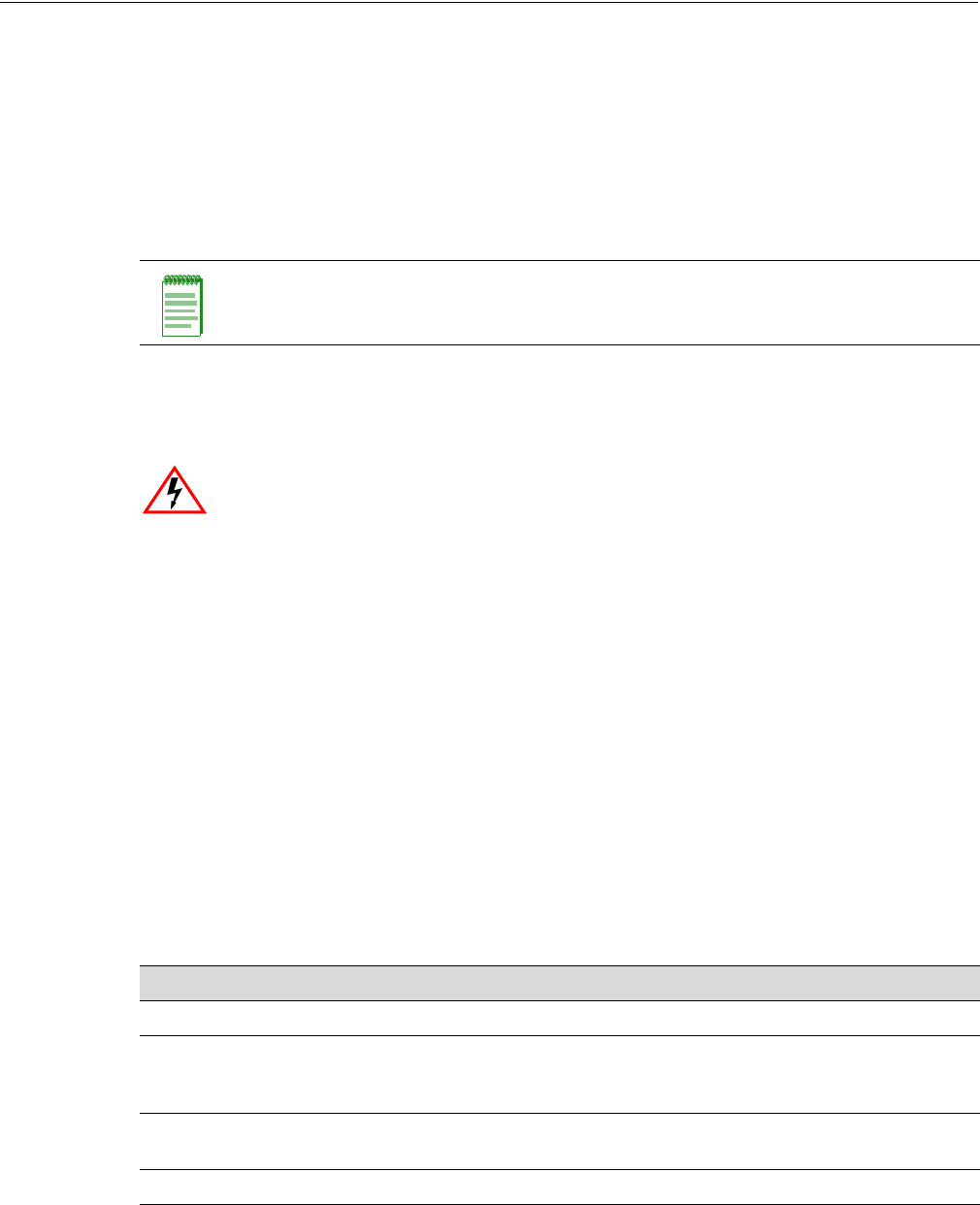
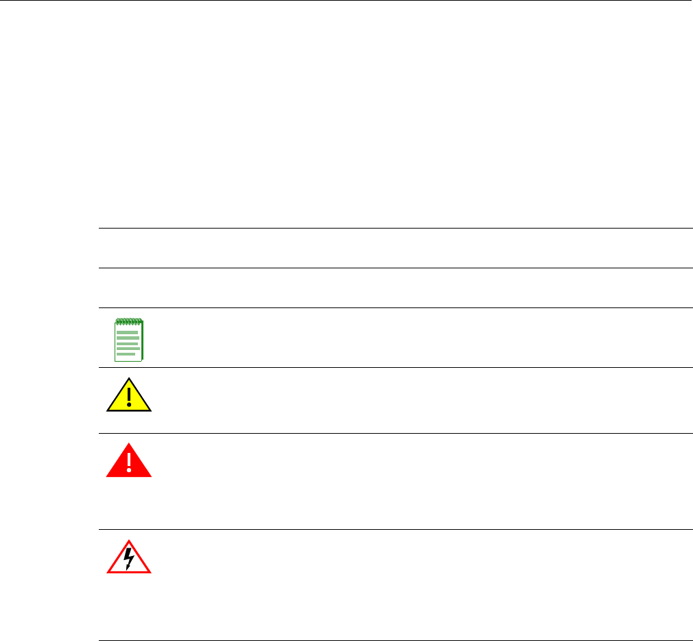
Note: Calls the reader’s attention to any item of information that may be of special
importance.
Caution: Contains information essential to avoid damage to the equipment.
Precaución: Contiene información esencial para prevenir dañar el equipo.
Achtung: Verweißt auf wichtige Informationen zum Schutz gegen Beschädigungen.
Warning: Warns against an action that could result in personal injury or death.
Advertencia: Advierte contra una acción que pudiera resultar en lesión corporal o la
muerte.
Warnhinweis: Warnung vor Handlungen, die zu Verletzung von Personen oder gar
Todesfällen führen können!
Electrical Hazard: Warns against an action that could result in personal injury or death.
Riesgo Electrico: Advierte contra una acción que pudiera resultar en lesión corporal o la
muerte debido a un riesgo eléctrico.
Elektrischer Gefahrenhinweis: Warnung vor sämtlichen Handlungen, die zu Verletzung
von Personen oder Todesfällen – hervorgerufen durch elektrische Spannung – führen
können!
DRAFT

Enterasys Wireless AP3710/AP3725 Installation Guide xi
Getting Help
For additional support related to the AP3710/AP3725 or this document, contact Enterasys
Networks using one of the following methods:
Before contacting Enterasys Networks for technical support, have the following data ready:
• Your Enterasys Networks service contract number
• A description of the failure
• A description of any action(s) already taken to resolve the problem (for example, changing
mode switches or rebooting the unit)
• The serial and revision numbers of all involved Enterasys Networks products in the network
• A description of your network environment (such as layout, cable type, other relevant
environmental information)
• Network load and frame size at the time of trouble (if known)
• The device history (for example, if you have returned the device before, or if this is a recurring
problem)
• Any previous Return Material Authorization (RMA) numbers
World Wide Web www.enterasys.com/support/
Phone 1-800-872-8440 (toll-free in U.S. and Canada)
or 1-978-684-1000
For the Enterasys Networks Support toll-free number in your country:
www.enterasys.com/support/
Internet mail support@enterasys.com
To expedite your message, please type [Wireless] in the subject line.
DRAFT

xii
DRAFT

Enterasys Wireless AP3710/AP3725 Installation Guide 1-1
1
Introduction
This installation guide provides an overview and installation instructions for the Enterasys
Wireless Access Points WS-AP3710 and WS-AP3725.
About the WS-AP3710 and WS-AP3725
The WS-AP3710 and WS-AP3725 access points are a cost-effective solution for extending your
wireless LAN around indoor locations. They interoperate fully with the Enterasys wireless LAN,
including support for Enterasys wireless VoWLAN, branch office mode, availability and mobility
features.
The WS-AP3710 and WS-AP3725 are nearly identical in appearance and have the following
features in common:
• Both operate in 802.11n mode, and also support 802.11a/802.11g and 802.11b standard legacy
devices.
• Both support two MIMO 3x3 (up to three 802.11n spatial streams).
• They provide two single band radios for dual-band, concurrent operation, optimized for
indoor antenna coverage:
– 5GHz (Radio 1) in any of the following modes: IEEE802.11 a/b/g and/or n
– 2.4GHz (Radio 2) in any of the following modes: IEEE802.11 a/b/g and/or n
• They are enclosed in a rectangular, compact case.
• Both come in “i” (internal antenna) and “e” (external antenna) models.
• Both models include a mounting bracket for mounting them to walls and drop ceilings. (For
mounting on drop ceilings, an optional T-bar rail clamp accessory is needed.)
• They provide 40MHz Bandwidth at 2.4/5GHz operation (Channel Bonding).
• They can be powered directly through the LAN using Power over Ethernet (PoE), or by an
external 120/240V AC/DC adaptor.
The Enterasys Wireless WS-AP3710 and WS-AP3725 APs are the mid-range and high-end models
(respectively) of the Enterasys Wireless AP37xx product family, along with the entry-level
For information about... Refer to page...
About the WS-AP3710 and WS-AP3725 1-1
WS-AP3710 Overview 1-2
WS-AP3725 Overview 1-7
Common Architectural Features 1-11
DRAFT

1-2 WS-AP3710 Overview
WS-AP3705i. Table 1-1 shows the comparative differences between the WS-AP3710 and
WS-AP3725 models.
WS-AP3710 Overview
The WS-AP3710 access point is available in two models:
• WS-AP3710i contains six internal single-band antennas
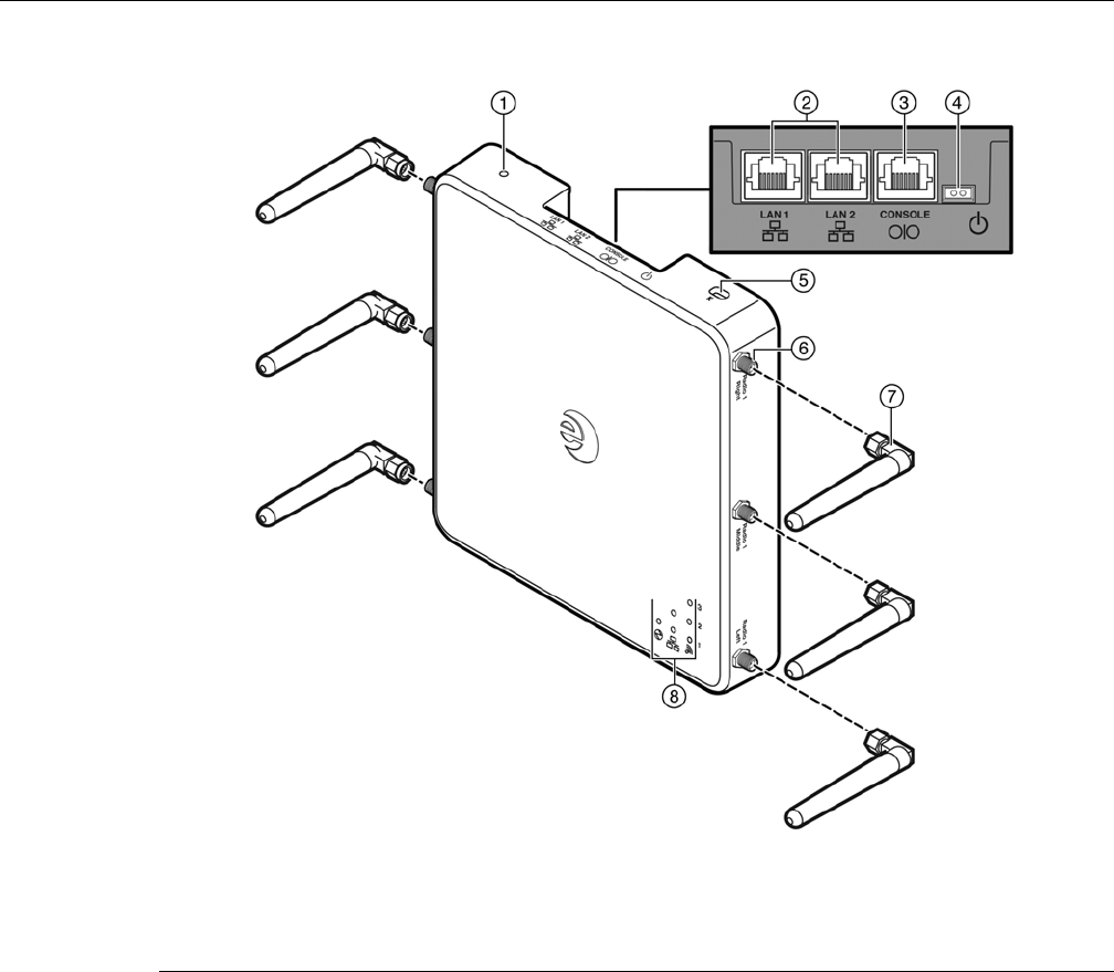
• WS-AP3710e contains six external RSMA connectors for optional external antennas, for
greater range and coverage versatility
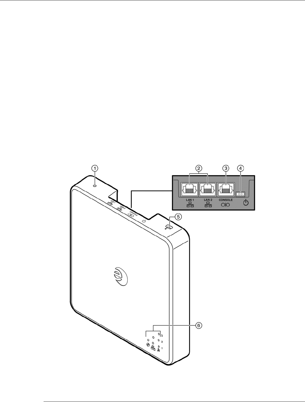
Figure 1-1 on page 1-3 shows the front view of the WS-AP3710i and Figure 1-2 on page 1-4 shows
the front view of the WS-AP3710e. Both figures also show the location of the LAN port, console
port, and external power supply connector.
Figure 1-3 on page 1-5 shows the back view of the WS-AP3710. Although the figure shows the
WS-AP3710e model, the back panel is the same for both models.
Figure 1-4 on page 1-6 illustrates the WS-AP3710 LEDs.
Table 1-1 WS-AP3710 and WS-AP3725 Differences
Feature WS-AP3710 WS-AP3725
Radios 2 3, including additional 2.4GHz/5GHz
radio (Radio 3) that operates as a sensor
radio
LEDs 4 6
1 Ghz Ethernet
Port
12
Power <12.9W;
802.3af
<24W;
802.3at
Antennas WS-AP3710i has 6 internal single-band
antennas
WS-AP3710e has 6 external RSMA
connectors
WS-AP3725i has 8 internal antennas (6
single-band ; 2 dual-band)
WS-AP3725e has 6 external RSMA
connectors
DRAFT
Enterasys Wireless AP3710/AP3725 Installation Guide 1-5
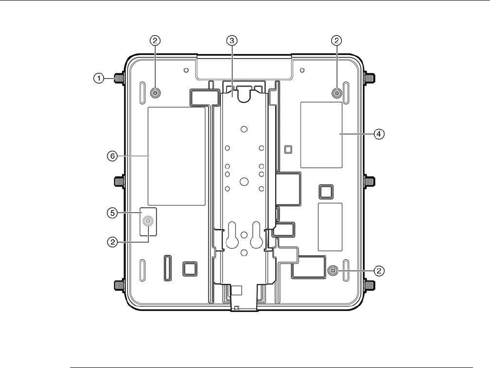
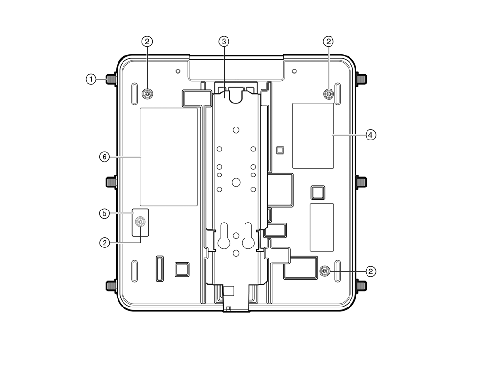
Figure 1-3 WS-AP3710 Back View (WS-AP3710e Model Shown)
1RSMA antenna connectors 4Product Label
2Back Plate Screws 5Tamper Evident Label
3Mount Bracket 6Regulatory Label
DRAFT
1-6 WS-AP3710 Overview
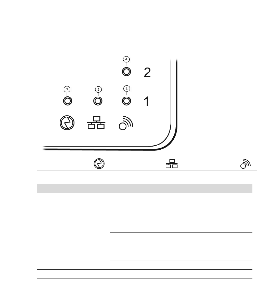
WS-AP3710 LED Indicators
Both models of the WS-AP3710 have four LED indicators, shown in Figure 1-4 below. The LEDs
provide status information, described in Table 1-2, on the current state of the WS-AP3710. For
more information, see the Enterasys Wireless Convergence Software User Guide.
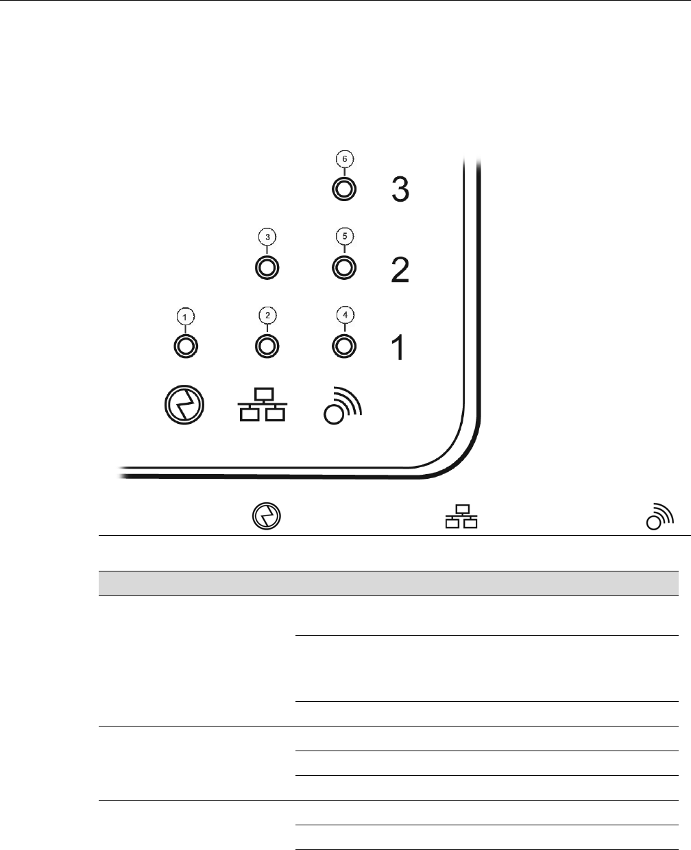
Figure 1-4 WS-AP3710 LEDs (Front, lower right)
Identifies Power
Indicator LED
Identifes LAN
Indicator LED
Identifies Radio
Indicator LEDs
Table 1-2 WS-AP3710 LED Indications
LED Status Description
1 (AP status) On Green Indicates the WS-AP3710 is working
normally.
Flashing Green Indicates:
• running a self test
• loading software program
On Red Indicates a CPU/system failure.
2 (Ethernet link state) On Green Indicates a valid 100Mbps Ethernet link.
On Blue Indicates a valid 1Gbps Ethernet link.
Off Indicates the link is down.
3 (Radio 1 status) On Green Indicates Radio 1 is enabled.
4 (Radio 2 status) On Green Indicates Radio 2 is enabled.
DRAFT
Enterasys Wireless AP3710/AP3725 Installation Guide 1-7
WS-AP3725 Overview
The WS-AP3725 is available in two models:
• WS-AP3725i contains eight internal single-band antennas, with six single-band antennas as in
the WS-AP3710i, and two additional dual band 2.4/5GHz antennas for radio 3.
• WS-AP3725e contains six external RSMA connectors: three are shared using a diplexer
between radio 1 and radio 2; three are directly connected (no diplexer) to radio 3
Radio 3 is used for concurrent dual band interference detection, wireless intrusion
detection/prevention and wireless capture.
Figure 1-5 on page 1-7 shows the front view of the WS-AP3725i and Figure 1-6 on page 1-8 shows
the front view of the WS-AP3725e. Both figures also show the location of the LAN port, console
port, and external power supply connector.
Figure 1-7 on page 1-9 shows the back view of the WS-AP3725. Although the figure shows the
WS-AP3725e model, the back panel is the same for both models.
Figure 1-8 on page 1-10 illustrates the WS-AP3725 LEDs.
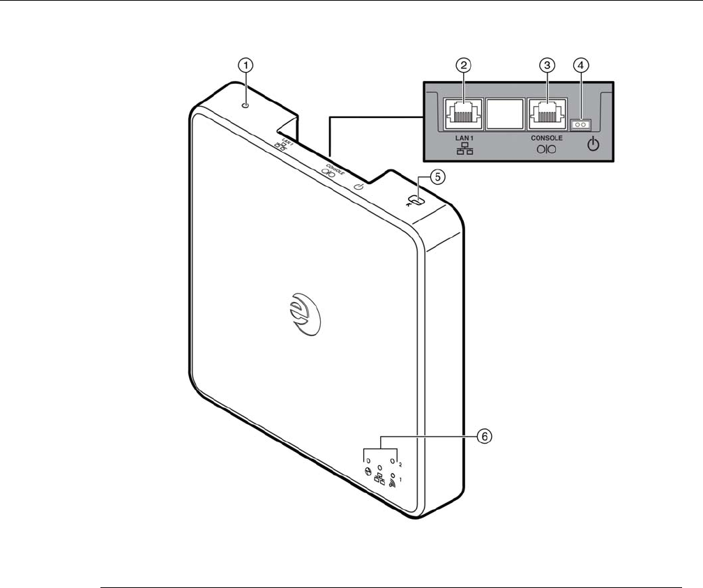
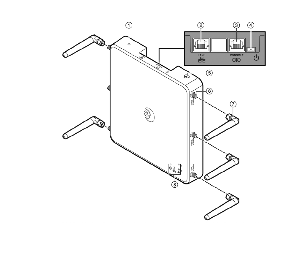
Figure 1-5 Enterasys Wireless AP3725i Front View
1Reset switch 4External power supply port
2LAN ports 5Slot for Kensington lock
3Console port 6LEDs (See Figure 1-8 on page 1-10 for details)
DRAFT
Enterasys Wireless AP3710/AP3725 Installation Guide 1-9
Figure 1-7 WS-AP3725 Back View (WS-AP3725e Model Shown)
1RSMA antenna connectors 4Product Label
2Back Plate Screws 5Tamper Evident Label
3Mounting Bracket 6Regulatory Label
DRAFT
1-10 WS-AP3725 Overview
WS-AP3725 LED Indicators
Both models of the WS-AP3725 have six LED indicators, as shown in Figure 1-8 below. The LEDs
provide status information, described in Table 1-3, on the current state of the WS-AP3725. For
more information, see the Enterasys Wireless Convergence Software User Guide.
Figure 1-8 WS-AP3725 LEDs (Front, lower right)
Identifies power
Indicator LED
Identifies LAN
Indicator LEDs
Identifies Radio
Indicator LEDs
Table 1-3 WS-AP3725 LED Indications
LED Status Description
1 (AP status) On Green Indicates the WS-AP3710 is working
normally.
Flashing Green Indicates:
• running a self test
• loading software program
On Red Indicates a CPU/system failure.
2 (Ethernet 1 link state) On Green Indicates a valid 100Mbps Ethernet link.
On Blue Indicates a valid 1Gbps Ethernet link.
Off Indicates the link is down.
3 (Ethernet 2 link state) On Green Indicates a valid 100Mbps Ethernet link.
On Blue Indicates a valid 1Gbps Ethernet link.
Off Indicates the link is down.
DRAFT

Enterasys Wireless AP3710/AP3725 Installation Guide 1-11
Common Architectural Features
Console Port
The WS-AP3710 and WS-AP3725 both include a single RJ45 console port (shown in Figure 1-1 on
page 1-3 and Figure 1-5 on page 1-7) for debug purposes. This port enables connection of a console
device to the AP through a serial cable. The console device can be a PC or workstation running a
VT-100 terminal adapter emulator, or a VT-100 terminal.
LAN Port
The WS-AP3710 has one 10/100/1000BaseT RJ45 LAN port (see Figure 1-1 on page 1-3) that can be
attached directly to a 10/100/1000BaseT LAN segment. This segment must conform to the IEEE
802.3 or 802.3u specifications. The WS-AP3725 has two such ports, as shown in Figure 1-5 on
page 1-7.
The APs appear as Ethernet nodes and perform a bridging function by moving packets from the
wired LAN to remote workstations on the wireless infrastructure.
The LAN ports also support power over Ethernet (PoE) based on the IEEE 802.3at standard. Refer
to “Installation” on page 2-1, for information on supplying power to the AP network port from a
network device, such as a switch, that provides Power over Ethernet (PoE).
Reset Switch
The WS-AP3710 and WS-AP3725 both provide a Reset Switch to reset or restore factory default
configurations. Use a pen tip or a nail to press the switch button through the hole (located on the
top side of the AP). If you hold down the button for less than 5 seconds, the AP performs a
software interrupt, causing it to drop all connections and reset. If you hold the button down for 5
seconds or more, any configuration changes are removed, and the factory default configuration
restores to the AP.
Kensington Lock Slot
There is a slot for a Kensington lock on the top side of the AP. See Kensington lock documentation
for instructions on use of the lock.
4 (Radio 1 status) On Green Indicates Radio 1 is enabled.
5 (Radio 2 status) On Green Indicates Radio 2 is enabled.
6 (Radio 3 status) On Green Indicates Radio 3 is enabled.
Table 1-3 WS-AP3725 LED Indications (continued)
LED Status Description
DRAFT

1-12 Common Architectural Features
DRAFT

Enterasys Wireless AP3710/AP3725 Installation Guide 2-1
2
Installation
This chapter provides installation instructions for the Enterasys Wireless WS-AP3710 and
WS-AP3725 access points and the optional AP power supply.
Unpacking the WS-AP3710 and WS-AP3725
To unpack the access point:
1. Open the box and remove the packing material protecting the AP.
2. Verify that the carton contains the items listed in Table 2-1.
3. Perform a visual inspection of the AP for any signs of physical damage. Contact Enterasys
Networks if there are any signs of damage. Refer to “Getting Help” on page xi for details.
Accessories
The following accessories are available for the Enterasys Wireless AP3710/AP3725. For ordering
information, contact your Enterasys sales representative.
• 48V DC power supply, part number WS-AP3X48-MR
• Ceiling T-bar rail mount kit, part number WS-MB3700-01
For information about... Refer to page...
Unpacking the WS-AP3710 and WS-AP3725 2-1
Accessories 2-1
Access Point Installation Procedures 2-2
Table 2-1 AP3710/AP3725 Package Contents
Quantity Item
1 AP3710/AP3725
1 Mounting Bracket with screw
1 Quick Reference card
DRAFT
Access Point Installation Procedures
2-2 Installation
Access Point Installation Procedures
These procedures describe how to attach the AP3710/AP3725 to a drop ceiling (flat or protruded),
how to mount the AP to a wall, and how to mount the AP on an existing AP mount plate or a
junction box.
Mounting the AP3710/AP3725 to a Drop Ceiling
To mount the AP to a drop ceiling, you need the separately orderable T-bar rail mount kit
(WS-MB3700-01). T-bar rail clamps can be used to mount APs on flat or protruded drop ceilings.
To attach the AP3710/AP3725 to a drop ceiling:
1. Attach the first of the two T-bar rail clamps (it doesn’t matter which) to the universal mount
bracket that ships with the access point. Place the clamp against the top of the plate so that its
two screw holes match up to the topmost pair of countersink holes, and screw in the provided
screws from underneath the mounting bracket as shown in Figure 2-1.
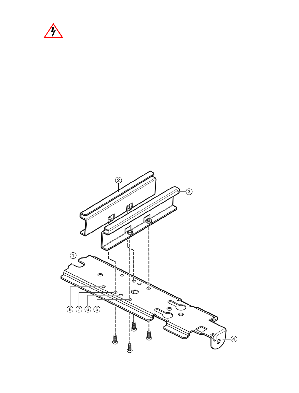
Figure 2-1 Mounting Bracket and T-bar Rail Clamp
Electrical Hazard: This product should be installed and serviced by a qualified licensed technician,
electrician, or electrical maintenance person familiar with its operation and the hazards involved.
1Mounting Bracket 5Top Pair Countersink Holes
2T-bar Rail Clamp 2 6Countersink Hole Pair for 9/16” Rail
3T-bar Rail Clamp 1 7Countersink Hole Pair for 15/16” Rail
4Locking Tab 8Countersink Hole Pair for 1.5” Rail
DRAFT
Access Point Installation Procedures
Enterasys Wireless AP3710/AP3725 Installation Guide 2-3
2. Attach the second T-bar rail clamp to the bracket with its two screw holes matching up to the
pair of countersink holes at the width needed for the rails you have, as shown Figure 2-1. Turn
the screws into the mount bracket countersink holes from beneath, no more than one or two
turns so the second clamp is attached but loose.
3. Remove the ceiling panels around the drop ceiling T-bar rails where you intend to mount the
AP. Verify that the Ethernet cable that will connect to the AP can reach the AP at the point
where you plan to mount it.
4. Hold the bracket and clamp assembly in one hand with the two clamps spread and held apart
by a finger, and fit the edges of the clamps over the T-bar rail on both sides of the rail at once.
Release the clamps over the rail and tighten the screws the rest of the way in the countersink
holes.
5. Fit the back of the AP against the mounting bracket with the locking tab aligned with the lock
screw hole, and slide it backward so that the end of the AP is against the locking tab, as shown
in Figure 2-2.
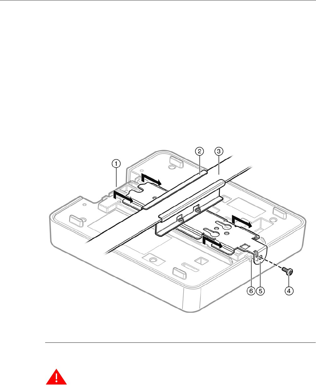
Figure 2-2 Attaching the AP to the Ceiling Mount Assembly
6. Screw the mounting screw into the locking tab and hole to secure the AP in place
(Figure 2-2).
7. Make a hole through the ceiling panel closest to the connector bay on the AP. Then run the
Ethernet cable through the hole and into the LAN port (RJ45 Ethernet port) in the connector
bay.
8. Replace the displaced ceiling panels.
1Connector Bay 4Locking Screw
2Bracket and Clamp Assembly 5Locking Tab
3T-bar Rail 6Locking Screw Hole
Warning: If the screw is not inserted as described in this step, there is a strong risk the
Enterasys Wireless AP3710/AP3725 will fall from the bracket.
DRAFT
Access Point Installation Procedures
2-4 Installation
Mounting the AP3710/AP3725 to a Wall
Mounting the access point to a wall uses the mounting bracket that ships with the AP. Screws for
attaching the AP to a wall are not supplied with the product, however, because the type and
length of the screws will depend on the wall type and thickness.
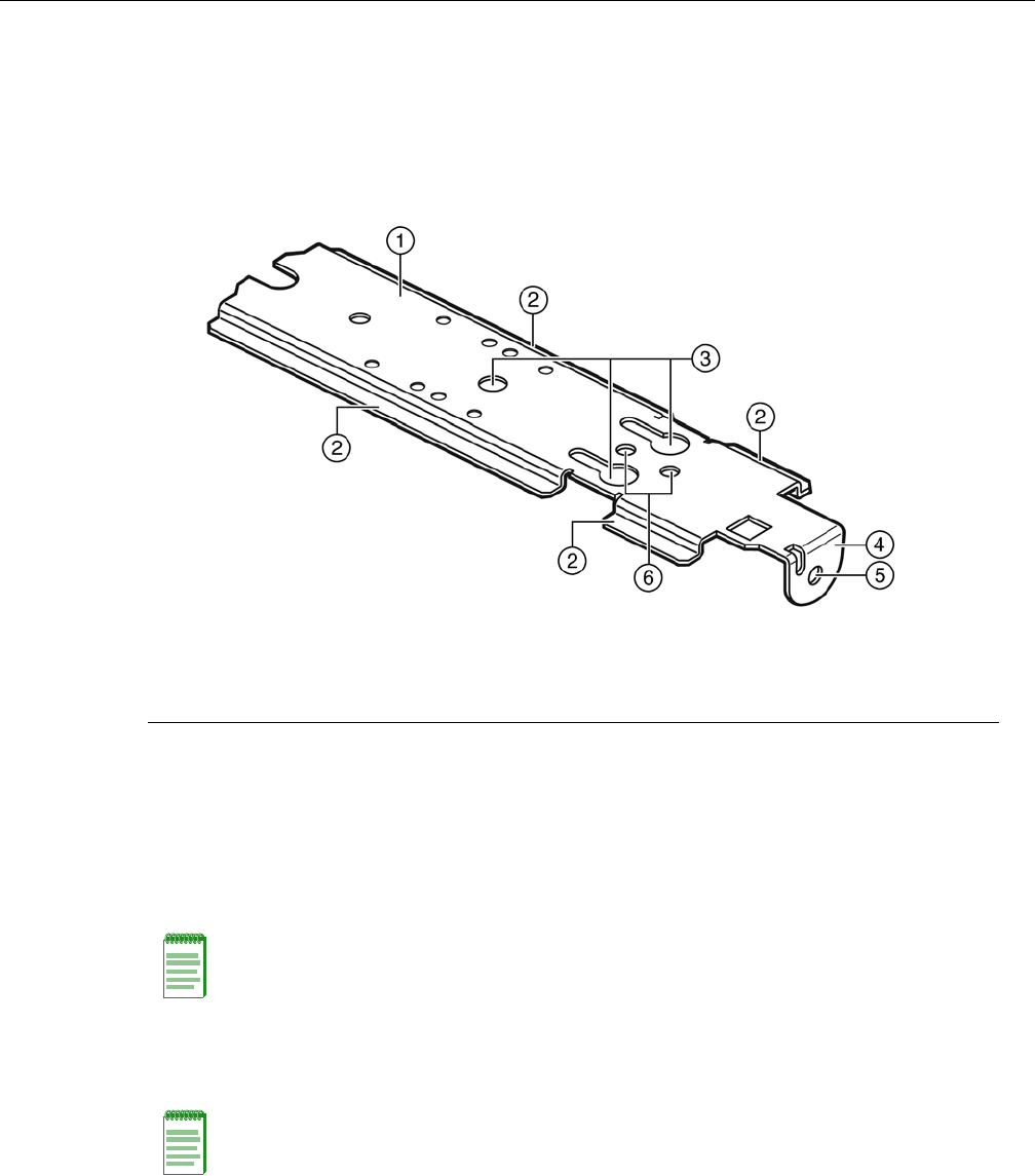
Figure 2-3 Wall Mounting Bracket
To attach the AP3710/AP3725 to a wall:
1. Determine the spot on the wall where the AP is to be mounted, preferably high up on the wall
(near the ceiling for maximum radio wave dispersion) but in reach of the Ethernet cable and a
wall power outlet if you are not able to use Power over Ethernet.
2. Place the flat side of the AP wall mounting bracket firmly against the wall surface, with the
locking tab facing out, and at the bottom.
3. Secure the bracket to the wall with three screws (see Figure 2-4 on page 2-5) through the
central wall mounting holes.
1Mounting Bracket, flat side up 4Locking Tab
2Bracket Side Rails 5Locking Screw Hole
3Wall mounting holes 6Junction Box Screw Holes
Note: The recommended orientation for the bracket is mounted on the wall vertically with the
locking tab at the bottom. This means the AP will be mounted with the cable ports at the top. The
bracket may be reversed (with locking tab at the top) so that the cable ports are at the bottom, but
this requires holding the AP in place until the locking screw is firmly screwed in.
Note: Screws for attaching the AP to a wall are not supplied with the product. The type and length
of the screws will depend on the wall type and thickness.
DRAFT
Access Point Installation Procedures
Enterasys Wireless AP3710/AP3725 Installation Guide 2-5
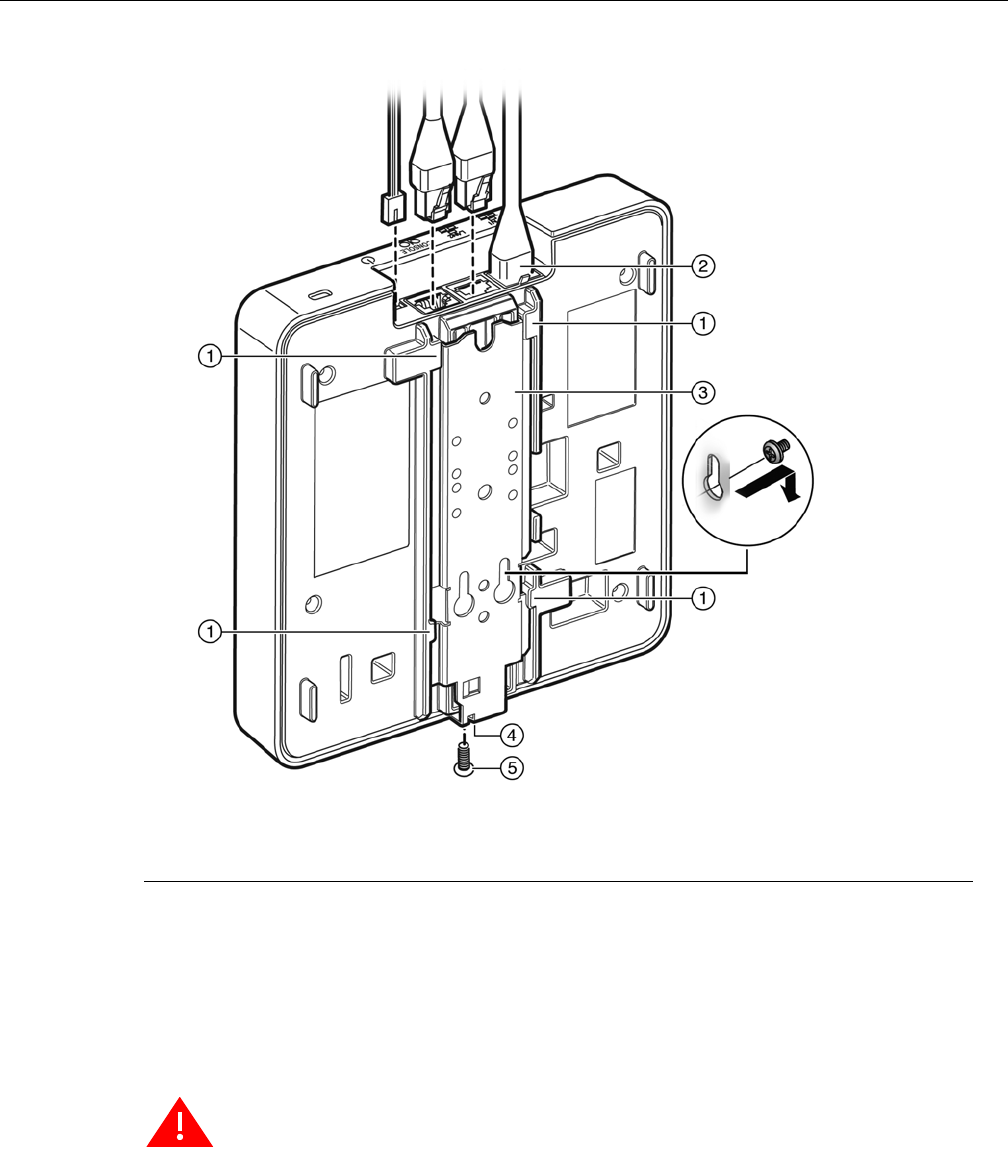
Figure 2-4 Mounting the AP on the Mounting Bracket
4. Plug the Ethernet cable into the RJ-45 port (and plug the power cord into the power port, if
applicable) on the back of the AP before mounting the AP on the bracket.
5. Place the back of the AP against the mounting bracket so that the bracket side rails fit into the
rail slots on the back of the AP and the locking screw hole in the AP aligns with the locking
tab. Slide the AP down until the AP rests on the locking tab, and screw in the locking screw
through the locking tab and locking screw hole. Figure 2-4 shows what the AP would look like
with the mounting bracket in place.
Mounting on a Junction Box, or in Place of an Older AP
You can replace an older AP or mount the AP3710/AP3725 on a junction box.
1. If there is a mounting bracket plate already in place from an older AP model, remove it.
2. Attach the AP mounting bracket where the older mounting bracket was, or directly to a
junction box, with two screws through the bracket junction box screw holes into the
1Rail slots 4Locking Tab and Locking Screw Hole
2Ethernet Cables 5Locking Screw
3Mounting Bracket
Warning: If the locking screw is not inserted as described in this step, there is a strong risk the
Enterasys Wireless AP3710/AP3725 will fall from the bracket.
DRAFT

Access Point Installation Procedures
2-6 Installation
corresponding holes on the junction box (see Figure 2-3 for location of junction box screw
holes).
3. Plug the Ethernet cable into the RJ-45 port (and plug the power cord into the power port, if
applicable) on the back of the AP before mounting the AP on the bracket.
4. Place the back of the AP against the mounting bracket so that the bracket side rails fit into the
rail slots on the back of the AP and the locking screw hole in the AP aligns with the locking
tab. Slide the AP down until the AP rests on the locking tab, and screw in the locking screw
through the locking tab and locking screw hole. Figure 2-4 on page 2-5 shows what the AP
would look like with the mounting bracket in place.
LAN/Console Connections
The WS-AP3710 has both a LAN and a Console port. Refer to Figure 1-1 on page 1-3 for the
location of these ports. The WS-AP3725 has two LAN ports and a Console port. Refer to Figure 1-5
on page 1-7 for the location of these ports.
During administration and maintenance through the LAN or Console, the AP must have a power
connection through either an Ethernet PoE cable or a DC power supply.
Power Connections
The AP can be powered in one of the following ways:
• Power over Ethernet (PoE)
Power is provided through the RJ45 Ethernet port (LAN port) on the top of the AP. This is the
preferred method of powering the AP on ceiling and high wall installations.
• Power by external power supply
Where a PoE-capable Ethernet connection is unavailable or impractical, an external 48V DC
power supply (WS-AP3X48-MR) may be ordered separately to power the AP from a standard
AC wall outlet. For more information on the installation process, see Connecting the DC
Power Supply to the AP3710/AP3725 below.
Connecting the DC Power Supply to the AP3710/AP3725
There is no wall mount for the WS-AP3X48-MR 48V DC power supply. To connect the power
supply to the AP for everyday operation, mount the AP and plug in the power supply as
described in Mounting the AP3710/AP3725 to a Wall. If you have taken the AP off its mount for
configuration and maintenance, plug the power cable from the DC power supply into the DC
connector on the top of the AP.
Warning: If the screw is not inserted as described in this step, there is a strong risk the
Enterasys Wireless AP3710/AP3725 will fall from the bracket.
DRAFT

Access Point Installation Procedures
Enterasys Wireless AP3710/AP3725 Installation Guide 2-7
Figure 2-5 AP 48V DC Power Supply
Figure TBD
DRAFT

Access Point Installation Procedures
2-8 Installation
DRAFT

Enterasys Wireless AP3710/AP3725 Installation Guide A-1
A
Specifications
This appendix lists the specifications for the WS-AP3710 and WS-AP3725 access points and the
Enterasys 48V DC power supply.
Table A-1 Specifications for the WS-AP3710 and WS-AP3725
Item Specification
Enclosure material Metal base, plastic housing
Power source 802.3af compliant PoE PD,
48V DC input
Power consumption < 12.94W (Max.)
Outside dimensions (max) WS-AP3725 Length: 190.5mm (7.5")
Width: 145mm to 180.0mm (7.5" to 7.09")
Thickness (not including mounting bracket): 29mm (1.13") to
38mm (1.5").
Antenna (AP3710i only) 6x internal antennas, single band
Uplink Interface GbE Ethernet x1 with PoE
RoHS compliant Yes
Radio Configuration IEEE 802.11a/b/g/n,
2.4/5GHz single-band,
Dual-radio, 3x3:2 MIMO
Operating temperature 32o F to 122o F (0o C to +50o C)
DRAFT

A-2
Table A-2 Specifications for the AP Power Supply (WS-AP3X48-MR)
Item Specification
Enclosure material Plastic housing
AC Input 90 to 264V
DC output 48V
Outside dimensions (max) 8.5 x 4.8 inches
54 x 31 x 95.5mm
Weight 200 g.
RoHS compliant Yes
Operating temperature 0o C to +50o C
DRAFT
Enterasys Wireless AP3710/AP3725 Installation Guide B-1
B
Regulatory Information
This appendix provides regulatory information for the Enterasys Wireless WS-AP3710 and WS-
AP3725 access points.
Enterasys Wireless WS-AP3710 and WS-AP3725
The following regulatory information applies to the Enterasys Wireless access points WS-AP3710
and WS-AP3725.
United States
FCC Declaration of Conformity Statement
This device complies with Part 15 of the FCC Rules. Operation is subject to the following two
conditions:
• This device may not cause harmful interference.
• This device must accept any interference received, including interference that may cause
undesired operation.
This equipment has been tested and found to comply with the limits for a Class B digital device,
pursuant to Part 15 of the FCC Rules. These limits are designed to provide reasonable protection
against harmful interference when the equipment is operated in a residential and business
environment. This equipment generates, uses, and radiates radio frequency energy, and if not
installed and used in accordance with instructions, may cause harmful interference. However,
there is no guarantee that interference will not occur. If this equipment does cause harmful
Warning: Warnings identify essential information. Ignoring a warning can lead to problems with the
application.
Note: Throughout this appendix, the term ‘Enterasys Wireless AP3710/AP3725’ refers to the AP
models WS-AP3710i, WS-AP3710e, WS-AP3725i, and WS-AP3725e. Specific AP models are only
identified in this appendix where it is necessary to do so.
Warning: Changes or modifications made to the Enterasys Wireless AP3710/AP3725 which are
not expressly approved by Enterasys could void the user's authority to operate the equipment.
Only authorized Enterasys service personnel are permitted to service the system. Procedures that
should be performed only by Enterasys personnel are clearly identified in this guide.
Note: The Enterasys Wireless AP3710/AP3725 is in compliance with the European Directive 2002/
95/EC on the restriction of the use of certain hazardous substances (RoHS) in electrical and
electronic equipment.
DRAFT

Enterasys Wireless WS-AP3710 and WS-AP3725
B-2
interference, which can be determined by turning the equipment off and on, the user is
encouraged to try to correct the interference by one or more of the following measures:
• Reorient or relocate the transmitting antenna.
• Increase the separation between the equipment or devices.
• Connect the equipment to an outlet other than the receiver's.
• Consult a dealer or an experienced radio/TV technician for suggestions.
USA Conformance Standards
This equipment meets the following conformance standards:
Safety
• UL 60950-1
EMC
• FCC CFR 47 Part 15, Class B
Radio transceiver
• CFR 47 Part 15.247, Subpart C
• CFR 47 Part 15.407, Subpart E
Other
• IEEE 802.11a (5 GHz)
• IEEE 802.11b/g (2.4 GHz)
• IEEE 802.11n
• IEEE 802.3af (PoE)
FCC RF Radiation Exposure Statement
The Enterasys Wireless AP3710/AP3725 complies with FCC RF radiated exposure limits set forth
for an uncontrolled environment. End users must follow the specific operating instructions for
satisfying RF exposure compliance. This device has been tested and has demonstrated compliance
when simultaneously operated in the 2.4 GHz and 5 GHz frequency ranges. This device must not
be co-located or operated in conjunction with any other antenna or transmitter.
The radiated output power of the Enterasys Wireless AP3710/AP3725 is below the FCC radio
frequency exposure limits as specified in “Guidelines for Human Exposure to Radio Frequency
Electromagnetic Fields” (OET Bulletin 65, Supplement C). This equipment should be installed and
Warning: The Enterasys Wireless AP3710/AP3725 must be installed and used in strict accordance
with the manufacturer's instructions as described in this guide and related documentation for the
device to which the Enterasys Wireless AP3710/AP3725 is connected. Any other installation or use
of the product violates FCC Part 15 regulations.
This Part 15 radio device operates on a non-interference basis with other devices operating at the
same frequency when using the antennas provided or other Enterasys-certified antennas. Any
changes or modifications to the product not expressly approved by Enterasys could void the user's
authority to operate this device.
For the product available in the USA market, only channels 1 to 11 can be operated. Selection of
other channels in the 2.4 GHz band is not possible.
DRAFT

Enterasys Wireless WS-AP3710 and WS-AP3725
Enterasys Wireless AP3710/AP3725 Installation Guide B-3
operated with a minimum distance of 25 cm between the radiator and your body or other co-
located operating antennas.
Canada
Industry Canada Compliance Statement
This digital apparatus does not exceed the Class B limits for radio noise emissions from digital
apparatus as set out in the interference-causing equipment standard entitled “Digital Apparatus,”
ICES-003 of Industry Canada.
Cet appareil numerique respecte les limites de bruits radioelectriques applicables aux appareils
numeriques de Classe B prescrites dans la norme sur le materiel brouilleur: “Appareils
Numeriques,” NMB-003 edictee par le Industrie Canada.
This device complies with RSS-210 of the Industry Canada Rules. Operation is subject to the
following conditions:
• This device may not cause harmful interference.
• This device must accept any interference received, including interference that may cause
undesired operation.
• This Class B digital apparatus complies with Canadian ICES-003.
• Operation in the 5150-5250 MHz band is only for indoor usage to reduce potential for harmful
interference to co-channel mobile satellite systems.
• Users are advised that high power radars are allocated as primary users (meaning they have
priority) and can cause interference in the 5250-5350 MHz and 5470-5850 MHz bands of LE-
LAN devices.
• For the product available in the Canadian market, only channels 1 to 11 can be operated.
Selection of other channels in the 2.4 GHz band is not possible.
• Under Industry Canada regulations, this radio transmitter may only operate using an antenna
of a type and maximum (or lesser) gain approved for the transmitter by Industry Canada. To
reduce potential radio interference to other users, the antenna type and its gain should be so
chosen that the equivalent isotropically radiated power (e.i.r.p.) is not more than that
necessary for successful communication.
Ce dispositif est conforme à la norme CNR-210 d'Industrie Canada applicable aux appareils radio
exempts de licence. Son fonctionnement est sujet aux conditions suivantes:
• Le dispositif ne doit pas produire de brouillage préjudiciable.
• Ce dispositif doit accepter tout brouillage reçu, y compris un brouillage susceptible de
provoquer un fonctionnement indésirable.
• Ce dispositif est conforme à la norme NMB-003 edictee par le Industrie Canada.
• Translation needed here — (Operation in the 5150-5250 MHz band is only for indoor usage to
reduce potential for harmful interference to co-channel mobile satellite systems.)
• Les utilisateurs devraient aussi être avisés que les utilisateurs de radars de haute puissance
sont désignés utilisateurs principaux (c.-à-d., qu'ils ont la priorité) pour les bandes 5250-5350
MHz et 5470-5850 MHz et que ces radars pourraient causer du brouillage et/ou des dommages
aux dispositifs LAN-EL.
• Translation needed here — (For the product available in the Canadian market, only channels 1
to 11 can be operated. Selection of other channels in the 2.4 GHz band is not possible.)
DRAFT

Enterasys Wireless WS-AP3710 and WS-AP3725
B-4
• Translation needed here — (Under Industry Canada regulations, this radio transmitter may
only operate using an antenna of a type and maximum (or lesser) gain approved for the
transmitter by Industry Canada. To reduce potential radio interference to other users, the
antenna type and its gain should be so chosen that the equivalent isotropically radiated power
(e.i.r.p.) is not more than that necessary for successful communication.)
Canada Conformance Standards
This equipment meets the following conformance standards:
Safety
• C22.2 No.60950-1-03
EMC
• ICES-003, Class B
Radio transceiver
• RSS-210 (2.4 GHz and 5GHz)
Other
• IEEE 802.11a (5 GHz)
• IEEE 802.11b/g (2.4 GHz)
• IEEE 802.11n
• IEEE 802.3af (PoE)
RF Safety Distance
The antennas used for this transmitter must be installed to provide a separation distance of at least
20 cm from all persons and must not be co-located or operating in conjunction with another
antenna or transmitter.
French translation needed here
European Community
The Enterasys Wireless AP3710/AP3725 is designed for use in the European Union and other
countries with similar regulatory restrictions where the end user or installer is allowed to
configure the Enterasys Wireless AP3710/AP3725 for operation by entry of a country code relative
to a specific country. After the country code is selected, the Enterasys Wireless AP3710/AP3725
uses the proper frequencies and power outputs for that country code.
The Enterasys Wireless AP3710/AP3725 is intended for indoor use and must be installed in a
proper indoor location. Contact local Authority for procedure to follow and regulatory
information. For more details on legal combinations of frequencies, power levels and antennas,
contact Enterasys.
Declaration of Conformity with R&TTE Directive of the European Union 1999/5/EC
The following symbol indicates compliance with the Essential Requirements of the R&TTE
Directive of the European Union (1999/5/EC).
DRAFT

Enterasys Wireless WS-AP3710 and WS-AP3725
Enterasys Wireless AP3710/AP3725 Installation Guide B-5
Declaration of Conformity in Languages of the European Community
English Hereby, Enterasys, declares that this Radio LAN device is in compliance with the essential
requirements and other relevant provisions of Directive 1999/5/EC.
Finnish Valmistaja Enterasys vakuuttaa täten että Radio LAN device tyyppinen laite on direktiivin
1999/5/EY oleellisten vaatimusten ja sitä koskevien direktiivin muiden ehtojen mukainen.
Dutch Hierbij verklaart Enterasys dat het toestel Radio LAN device in overeenstemming is met
de essentiële eisen en de andere relevante bepalingen van richtlijn 1999/5/EG.
Bij deze verklaart Enterasys dat deze Radio LAN device voldoet aan de essentiële eisen
en aan de overige relevante bepalingen van Richtlijn 1999/5/EC.
French Par la présente Enterasys déclare que l'appareil Radio LAN device est conforme aux
exigences essentielles et aux autres dispositions pertinentes de la directive 1999/5/CE.
Par la présente, Enterasys déclare que ce Radio LAN device est conforme aux exigences
essentielles et aux autres dispositions de la directive 1999/5/CE qui lui sont applicables.
Swedish Härmed intygar Enterasys att denna Radio LAN device står I överensstämmelse med de
väsentliga egenskapskrav och övriga relevanta bestämmelser som framgår av direktiv
1999/5/EG.
Danish Undertegnede Enterasys erklærer herved, at følgende udstyr Radio LAN device
overholder de væsentlige krav og øvrige relevante krav i direktiv 1999/5/EF.
German Hiermit erklärt Enterasys die Übereinstimmung des "WLAN Wireless Controller bzw.
Access Points" mit den grundlegenden Anforderungen und den anderen relevanten
Festlegungen der Richtlinie 1999/5/EG.
Greek ΜΕ ΤΗΝ ΠΑΡΟΥΣΑ Enterasys ∆ΗΛΩΝΕΙ ΟΤΙ Radio LAN device ΣΥΜΜΟΡΦΩΝΕΤΑΙ
ΠΡΟΣ ΤΙΣ ΟΥΣΙΩ∆ΕΙΣ ΑΠΑΙΤΗΣΕΙΣ ΚΑΙ ΤΙΣ ΛΟΙΠΕΣ ΣΧΕΤΙΚΕΣ ∆ΙΑΤΑΞΕΙΣ ΤΗΣ
Ο∆ΗΓΙΑΣ 1999/5/ΕΚ.
Icelandic Enterasys lysir her med yfir að thessi bunadur, Radio LAN device, uppfyllir allar
grunnkrofur, sem gerdar eru i R&TTE tilskipun ESB nr 1999/5/EC.
Italian Con la presente Enterasys dichiara che questo Radio LAN device è conforme ai requisiti
essenziali ed alle altre disposizioni pertinenti stabilite dalla direttiva 1999/5/CE.
Spanish Por medio de la presente Enterasys declara que el Radio LAN device cumple con los
requisitos esenciales y cualesquiera otras disposiciones aplicables o exigibles de la
Directiva 1999/5/CE.
Portuguese Enterasys declara que este Radio LAN device está conforme com os requisitos essenciais
e outras disposições da Directiva 1999/5/CE.
DRAFT

Enterasys Wireless WS-AP3710 and WS-AP3725
B-6
New Member States Requirements of Declaration of Conformity
European Conformance Standards
This equipment meets the following conformance standards:
Safety
• 2006/95/EC Low Voltage Directive (LVD)
• IEC/EN 60950-1 + National Deviations
EMC (Emissions / Immunity)
• 2004/108/EC EMC Directive
• EN 55011/CISPR 11, Class B, Group 1 ISM
• EN 55022/CISPR 22, Class B
• EN 55024/CISPR 24, includes IEC/EN 61000-4-2,3,4,5,6,11
• EN 61000-3-2 and -3-3 (Harmonics and Flicker)
• EN 60601-1-2 (EMC immunity for medical equipment)
• EN 50385 (EMF)
• ETSI/EN 301 489-1 & -17
Radio transceiver
• R&TTE Directive 1999/5/EC
• ETSI/EN 300 328 (2.4 GHz)
• ETSI/EN 301 893 (5 GHz)
Other
• IEEE 802.11a (5 GHz)
Malti Hawnhekk, Enterasys, jiddikjara li dan Radio LAN device jikkonforma mal-htigijiet
essenzjali u ma provvedimenti ohrajn relevanti li hemm fid-Dirrettiva 1999/5/EC.
Estonian Käesolevaga kinnitab Enterasys seadme Radio LAN device vastavust direktiivi 1999/5/EÜ
põhinõuetele ja nimetatud direktiivist tulenevatele teistele asjakohastele sätetele.
Hungary Alulírott, Enterasys nyilatkozom, hogy a Radio LAN device megfelel a vonatkozó alapvetõ
követelményeknek és az 1999/5/EC irányelv egyéb elõírásainak.
Slovak Enterasys týmto vyhlasuje, že Radio LAN device spĺňa základné požiadavky a všetky
príslušné ustanovenia Smernice 1999/5/ES.
Czech Enterasys tímto prohlašuje, že tento Radio LAN device je ve shodě se základními
požadavky a dalšími příslušnými ustanoveními směrnice 1999/5/ES."
Slovenian Šiuo Enterasys deklaruoja, kad šis Radio LAN device atitinka esminius reikalavimus ir
kitas 1999/5/EB Direktyvos nuostatas.
Latvian Ar šo Enterasys deklarē, ka Radio LAN device atbilst Direktīvas 1999/5/EK būtiskajām
prasībām un citiem ar to saistītajiem noteikumiem
Lithuanian Enterasys deklaruoja, kad Radio LAN device atitinka 1999/5/EC Direktyvos esminius
reikalavimus ir kitas nuostatas".
Polish Niniejszym, Enterasys, deklaruję, że Radio LAN device spełnia wymagania zasadnicze
oraz stosowne postanowienia zawarte Dyrektywie 1999/5/EC.
DRAFT
Enterasys Wireless WS-AP3710 and WS-AP3725
Enterasys Wireless AP3710/AP3725 Installation Guide B-7
• IEEE 802.11b/g (2.4 GHz)
• IEEE 802.11n
• IEEE 802.3af (PoE)
RoHS
• European Directive 2002/95/EC
Conditions of use in the European Community
Some EU countries allow outdoor operation with limitations and restrictions, which are described
in this section. It is the responsibility of the end user to ensure operation in accordance with these
rules, frequencies, and transmitter power output. The Enterasys Wireless AP3710/AP3725 must
not be operated until configured for the customer’s geographic location.
European Spectrum Usage Rules
The AP configured with approved internal antennas can be used for indoor transmissions
throughout the European community as displayed in Table B-1. Some restrictions apply in France,
Greece, and Italy.
Caution: The user or installer is responsible to ensure that the Enterasys Wireless AP3710/AP3725
is operated according to channel limitations, indoor / outdoor restrictions, license requirements, and
within power level limits for the current country of operation. A configuration utility has been
provided with the Wireless AP to allow the end user to check the configuration and make necessary
configuration changes to ensure proper operation in accordance with the spectrum usage rules for
compliance with the European R&TTE directive 1999/5/EC.
Caution: Please follow the instructions in this user guide to configure the Enterasys Wireless
AP3710/AP3725.
• Each Wireless AP is configured with a default group of settings. There is the ability to change
these settings. The user or installer is responsible to ensure that each Enterasys Wireless
AP3710/AP3725 is configured properly.
• The software within the Wireless AP automatically limits the allowable channels and output
power determined by the selected country code. Selecting the incorrect country of operation or
misidentifying the antenna being used,may result in illegal operation and may cause harmful
interference to other systems.
• This device employs a radar detection feature required for European Community operation in the
5 GHz band. This feature is automatically enabled when the country of operation is correctly
configured for any European Community country. The presence of nearby radar operation may
result in temporary interruption of operation of this device. The radar detection feature will
automatically restart operation on a channel free of radar.
• The 5150- 5350 MHz band, channels 36, 40, 44, 48, 52, 56, 60, or 64, are restricted to indoor
use only.
• The 2.4 GHz band, channels 1 - 13, may be used for indoor use but there may be some channel
restrictions.
• In France, outdoor operation is not permitted using the 2.4 - 2.454 GHz band.
Table B-1 European Spectrum Usage Rules
Country
5.15-5.25 (GHz)
Channels:
36,40,44,48
5.25-5.35 (GHz)
Channels:
52,56,60,64
5.47-5.725 (GHz)
Channels:
100,104,108,112,116,
132,136,140
2.4-2.4835 (GHz)
Channels: 1 to 13
(Except Where Noted)
Austria Indoor only Indoor only Indoor or outdoor Indoor or outdoor
DRAFT

Enterasys Wireless WS-AP3710 and WS-AP3725
B-8
Belgium Indoor only Indoor only Indoor or outdoor * Indoor or outdoor
Bulgaria Indoor only Indoor only Indoor or outdoor Indoor or outdoor
Croatia Indoor only Indoor only Indoor or outdoor Indoor or outdoor
Cyprus Indoor only Indoor only Indoor or outdoor Indoor or outdoor
Czech Rep. Indoor only Indoor only Indoor or outdoor Indoor or outdoor
Denmark Indoor only Indoor only Indoor or outdoor Indoor or outdoor
Estonia Indoor only Indoor only Indoor or outdoor Indoor or outdoor
Finland Indoor only Indoor only Indoor or outdoor Indoor or outdoor
France Indoor only Indoor only Indoor or outdoor Indoor only
Germany Indoor only Indoor only Indoor or outdoor Indoor or outdoor
Greece Indoor only Indoor only Indoor (Outdoor w/License) Indoor (Outdoor w/license)
Hungary Indoor only Indoor only Indoor or outdoor Indoor or outdoor
Iceland Indoor only Indoor only Indoor or outdoor Indoor or outdoor
Ireland Indoor only Indoor only Indoor or outdoor Indoor or outdoor
Italy Indoor only Indoor only Indoor or outdoor Indoor (Outdoor w/license)
Latvia Indoor only Indoor only Indoor or outdoor Indoor or outdoor
Liechtenstein Indoor only Indoor only Indoor or outdoor Indoor or outdoor
Lithuania Indoor only Indoor only Indoor or outdoor Indoor or outdoor
Luxembourg Indoor only Indoor only Indoor or outdoor Indoor or outdoor
Malta Indoor only Indoor only Indoor or outdoor Indoor or outdoor
Netherlands Indoor only Indoor only Indoor or outdoor Indoor or outdoor
Norway Indoor only Indoor only Indoor or outdoor Indoor or outdoor
Poland Indoor only Indoor only Indoor or outdoor Indoor or outdoor
Portugal Indoor only Indoor only Indoor or outdoor Indoor or outdoor
Romania Indoor only Indoor only Indoor or outdoor Indoor or outdoor
Slovak Rep. Indoor only Indoor only Indoor or outdoor Indoor or outdoor
Slovenia Indoor only Indoor only Indoor or outdoor Indoor or outdoor
Spain Indoor only Indoor only Indoor or outdoor Indoor or outdoor
Sweden Indoor only Indoor only Indoor or outdoor Indoor or outdoor
Switzerland Indoor only Indoor only Indoor or outdoor Indoor or outdoor
Turkey Indoor only Indoor only Indoor or outdoor Indoor or outdoor
U.K Indoor only Indoor only Indoor or outdoor Indoor or outdoor
Table B-1 European Spectrum Usage Rules (continued)
Country
5.15-5.25 (GHz)
Channels:
36,40,44,48
5.25-5.35 (GHz)
Channels:
52,56,60,64
5.47-5.725 (GHz)
Channels:
100,104,108,112,116,
132,136,140
2.4-2.4835 (GHz)
Channels: 1 to 13
(Except Where Noted)
DRAFT

Enterasys Wireless WS-AP3710 and WS-AP3725
Enterasys Wireless AP3710/AP3725 Installation Guide B-9
Certifications of Other Countries
The Enterasys Wireless AP3710/AP3725 has been certified for use in various other countries. Once
the correct country code is selected, the Wireless AP automatically uses the proper frequencies
and power outputs for that country code.
It is the responsibility of the end user to select the proper country code for the country within
which the device will be operated, or run the risk violating local laws and regulations.
.Other Country Specific Compliance Standards, Approvals and Declarations
• IEC 60950-1 CB Scheme + National Deviations
• AS/NZS 60950.1 (Safety)
• AS/NZS 3548 (Emissions via EU standards – ACMA)
• AS/NZS 4288 (Radio via EU standards)
• EN 300 328 (2.4 GHz)
• EN 301 893 (5 GHz)
• EN 301 489-1 & -17 (RLAN)
• IEEE 802.11a (5 GHz)
• IEEE 802.11b/g (2.4 GHz)
• IEEE 802.11n
• IEEE 802.3af (PoE)
RF Safety Distance
The antennas used for this transmitter must be installed to provide a separation distance of at least
25 cm from all persons and must not be co-located or operating in conjunction with another
antenna or transmitter.
DRAFT

Enterasys Wireless WS-AP3710 and WS-AP3725
B-10
DRAFT