Flextronics Special Business Solutions MWS-1000 Client (slave) unit User Manual MWB1300v3 12 100 UserGuide
Flextronics Special Business Solutions Ltd. Client (slave) unit MWB1300v3 12 100 UserGuide
UserManual.wiki
>
Flextronics Special Business Solutions
>
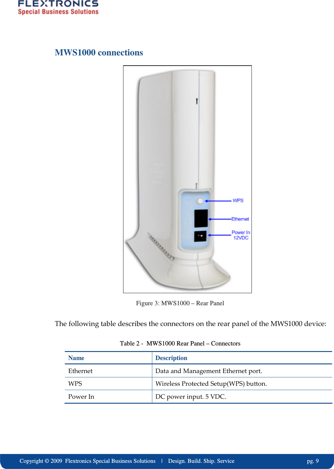
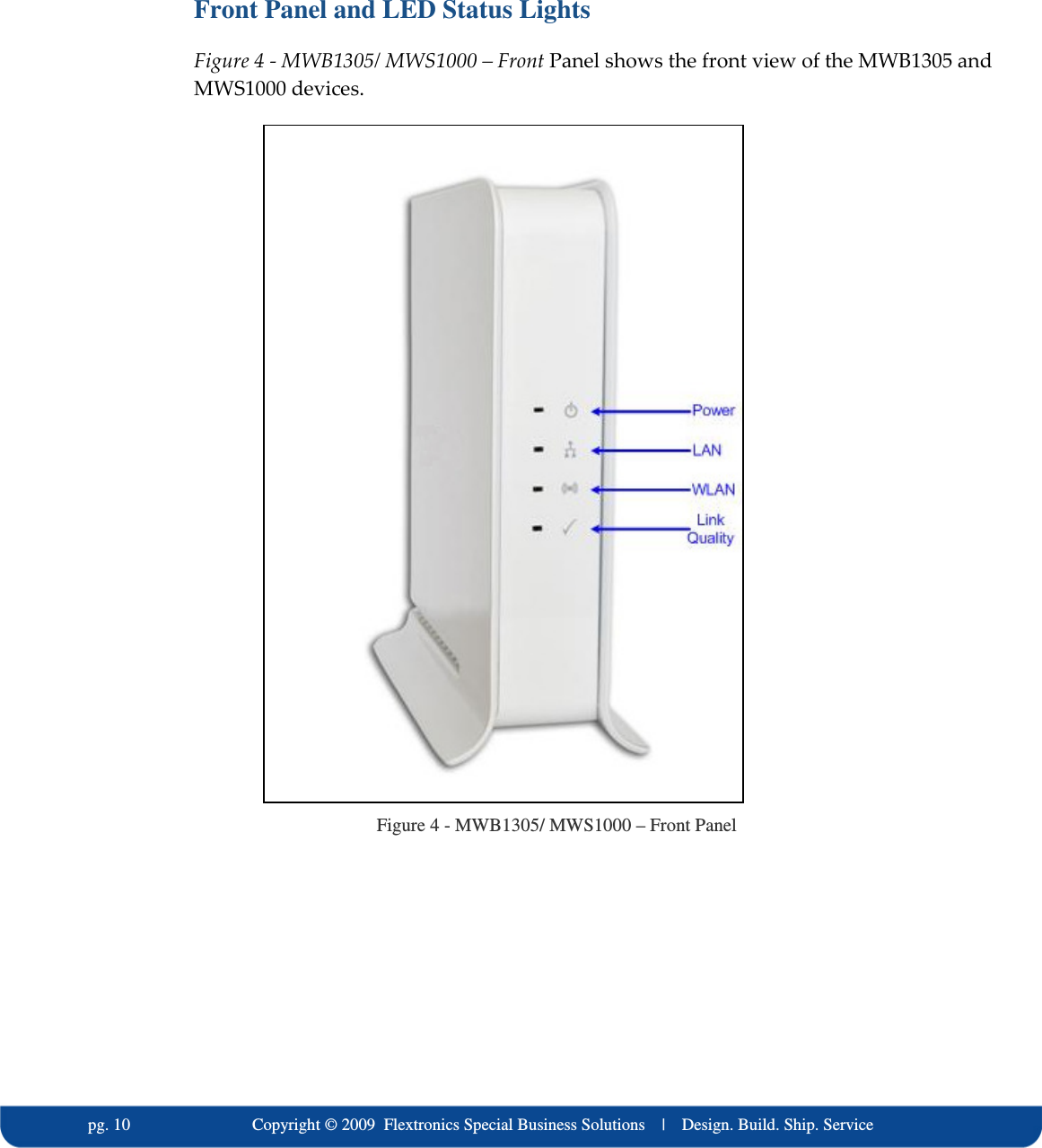
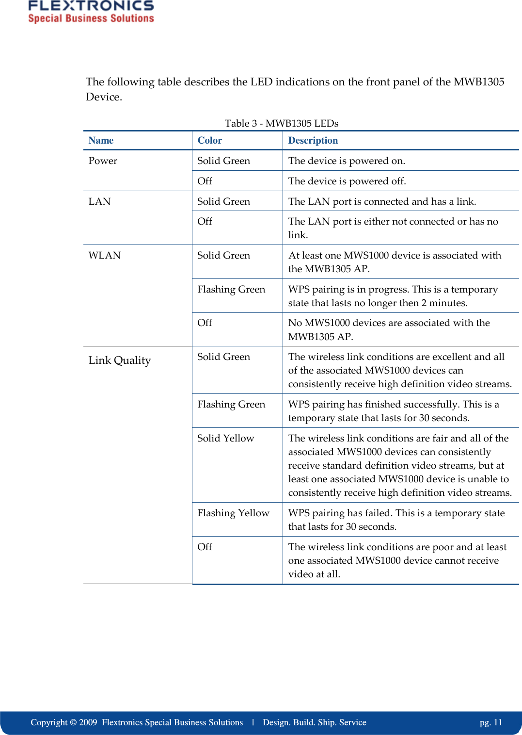
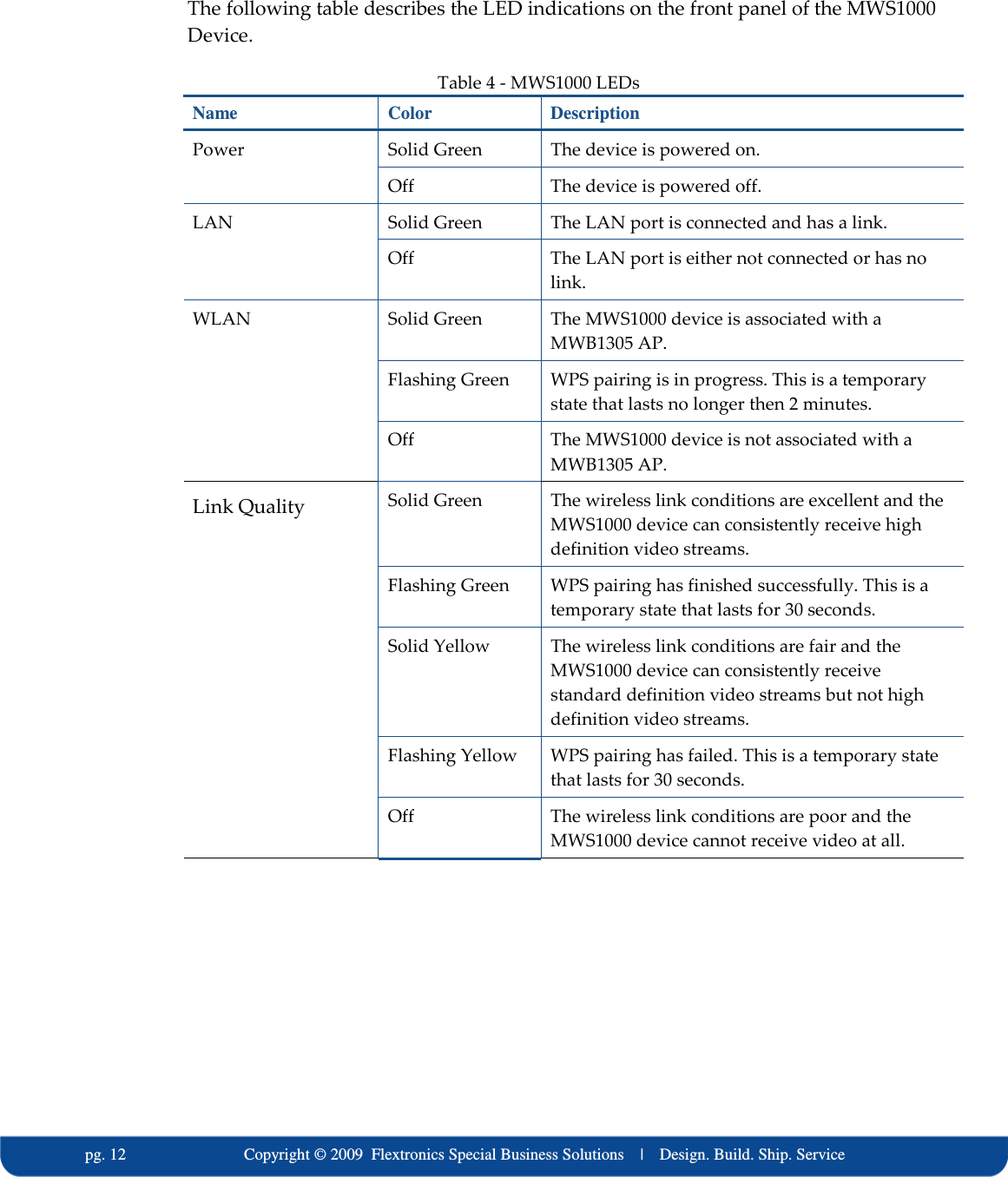
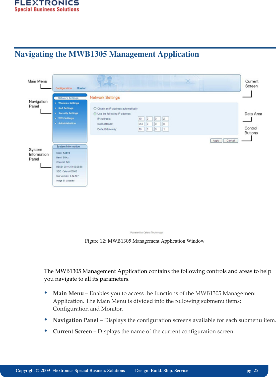
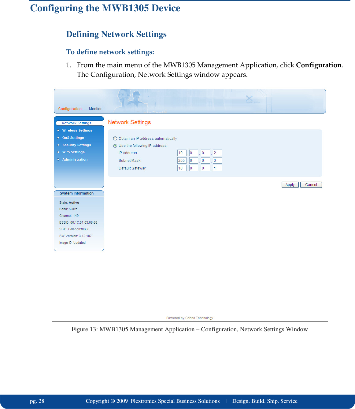
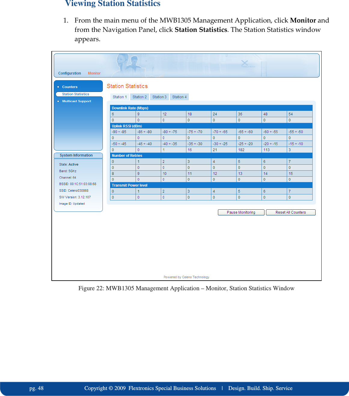
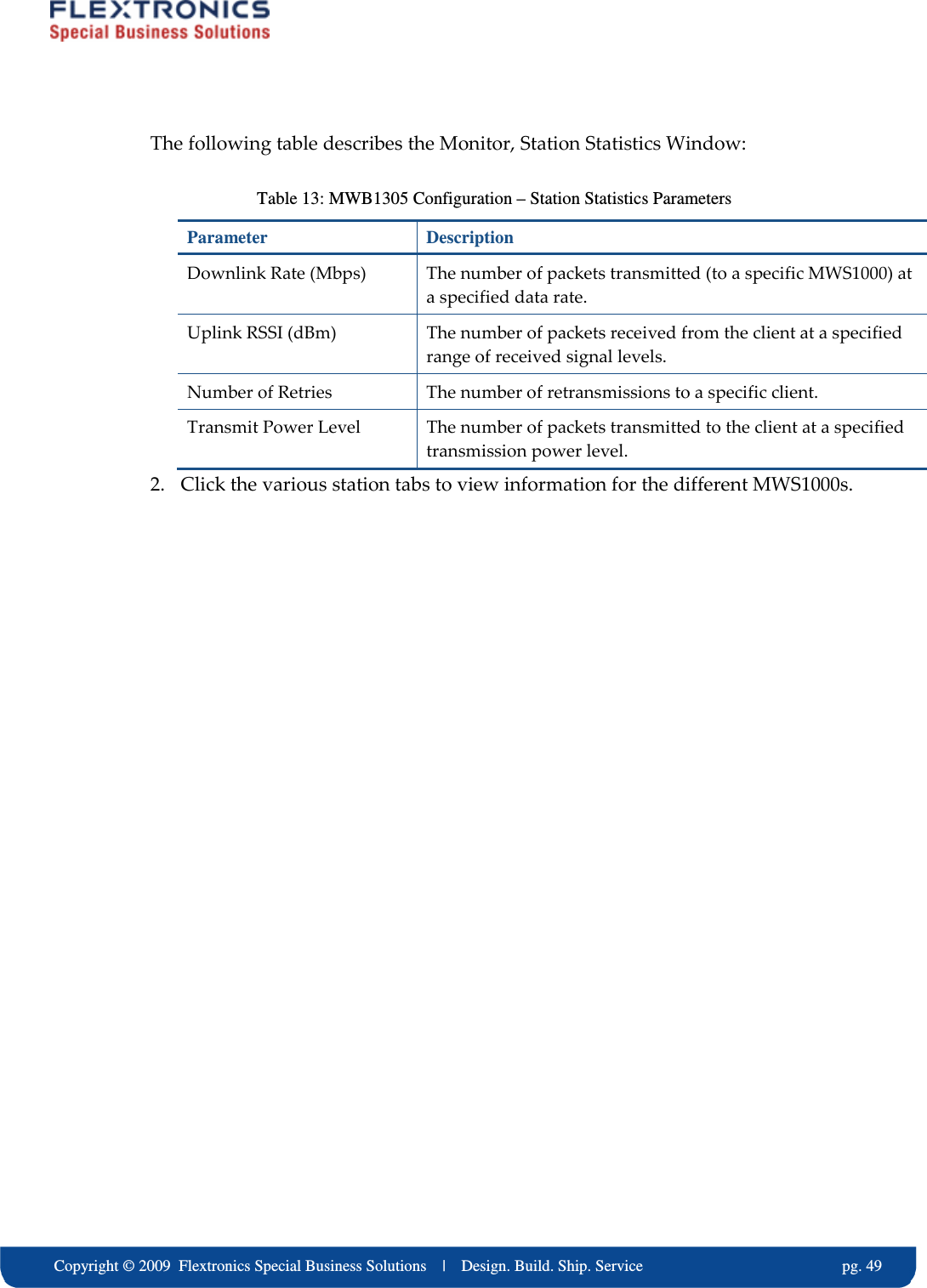
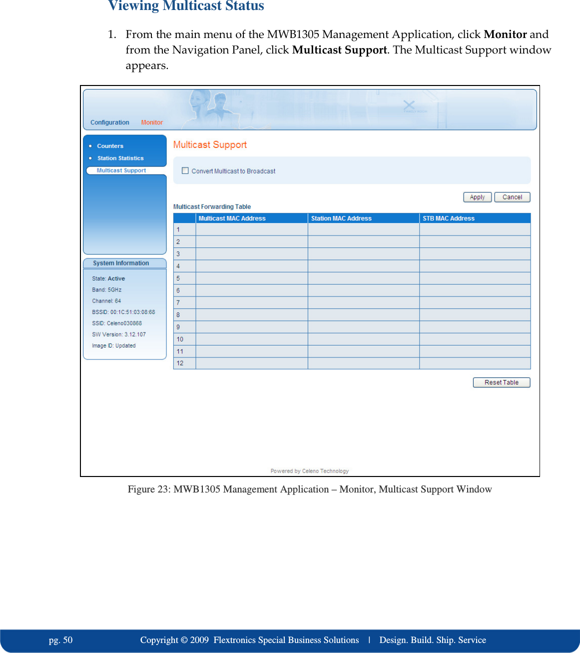
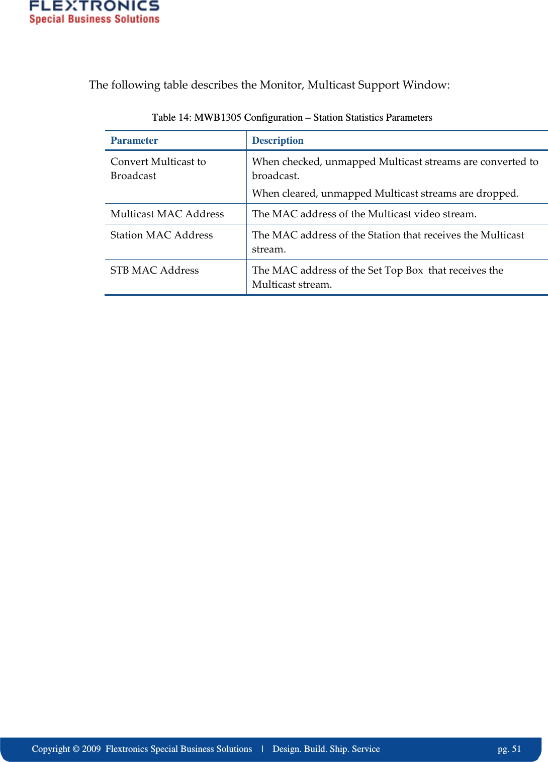
MWS 1000 User Manual
User manual
Navigation menu
Upload a User Manual
Namespaces
Wiki Guide
HTML
PDF
Info
Views
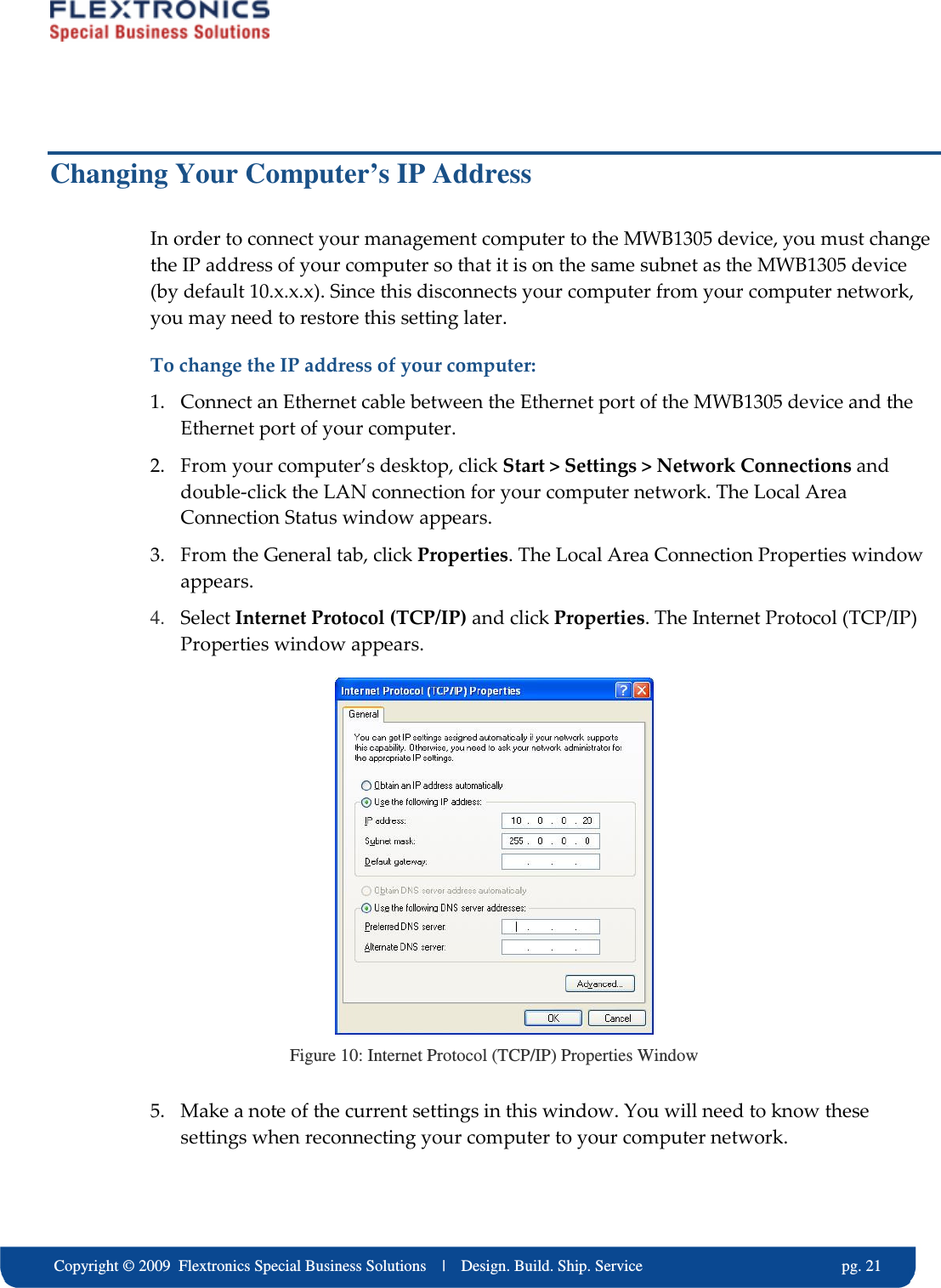
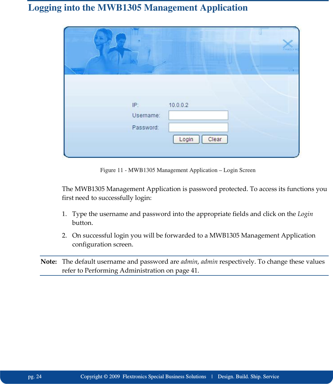
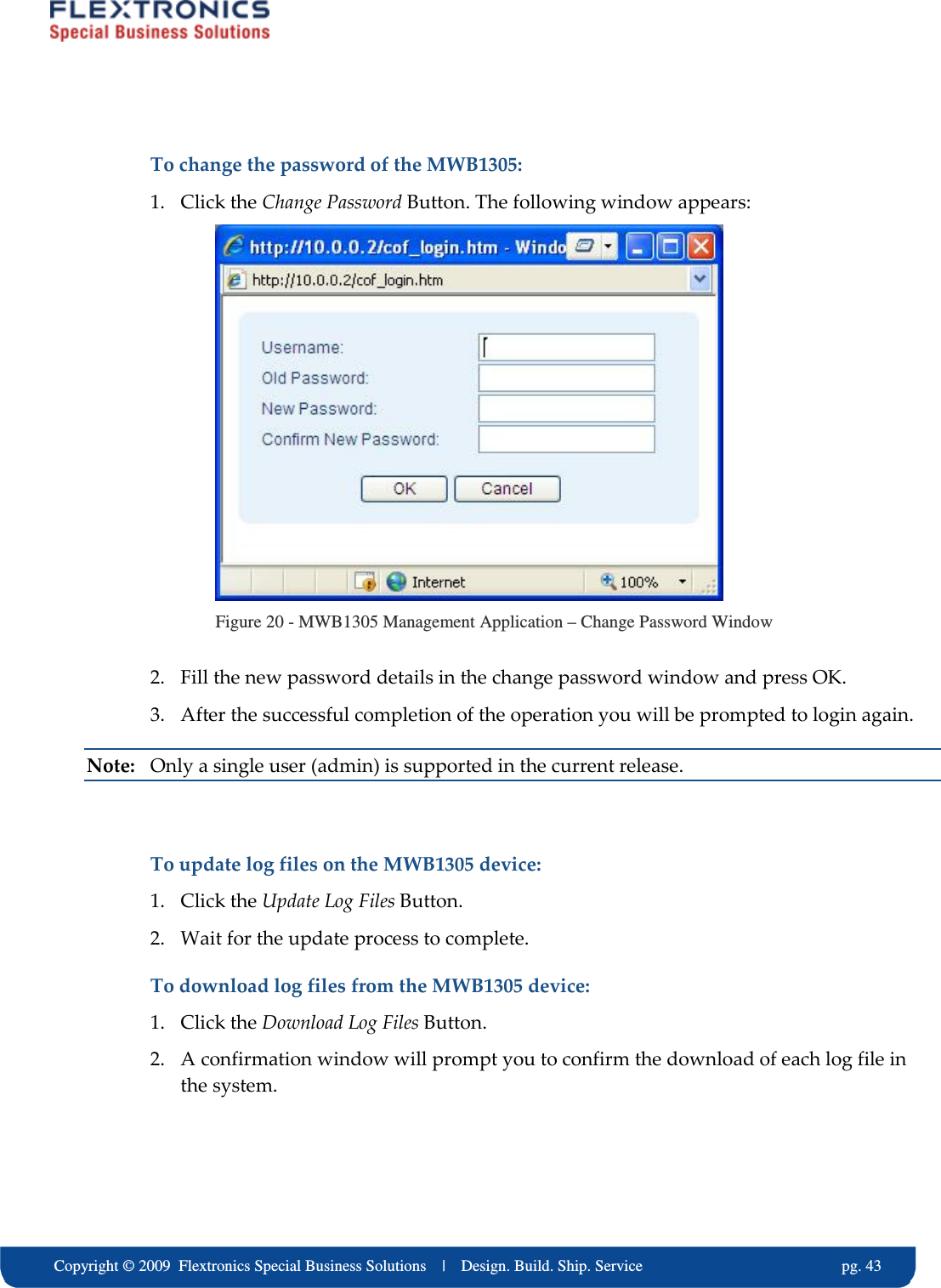
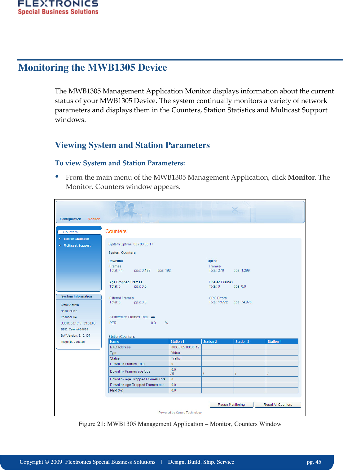
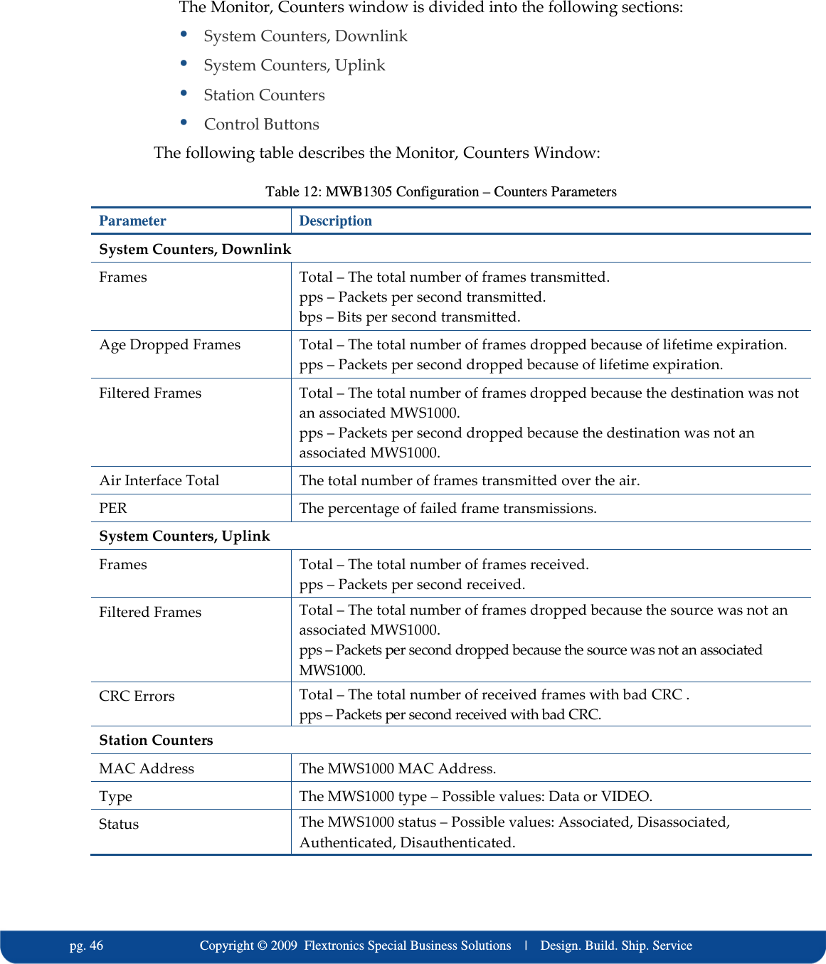
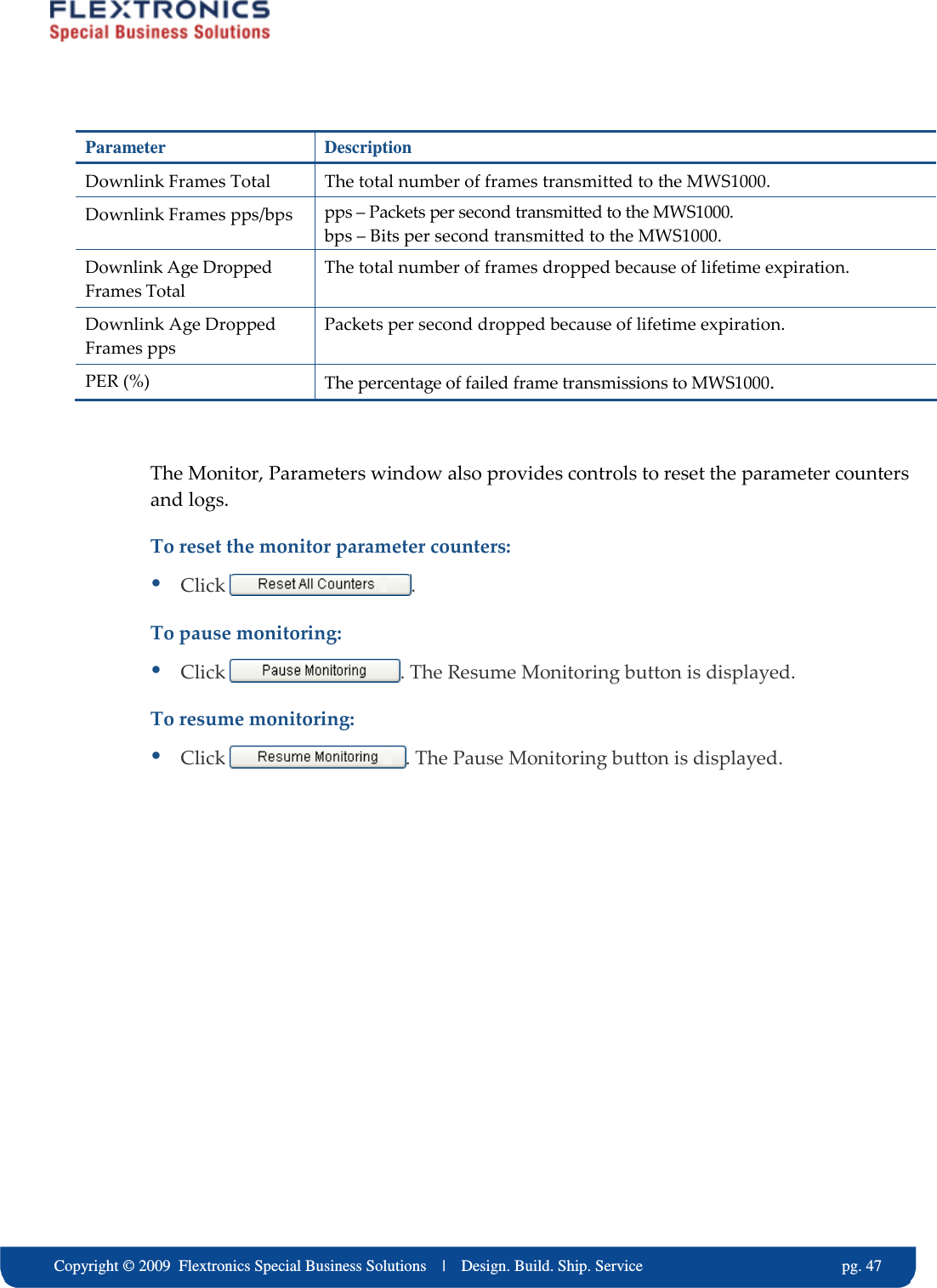
User Manual
Discussion / Help
Navigation