FlightScope PT238 Sports equipment motion measuring sensor User Manual 2
FlightScope (Pty) Ltd Sports equipment motion measuring sensor 2
UserManual.wiki
>
FlightScope
>
PT238 User Manual
>
User Manual 2
Contents
1.
User Manual 1
2.
User Manual 2
User Manual 2
Navigation menu
Upload a User Manual
Namespaces
Wiki Guide
HTML
PDF
Info
Views
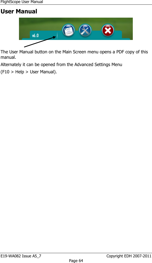
User Manual
Discussion / Help
Navigation