FlightScope TB101 Indoor Golf Sensor User Manual Part 15 with 38 dB rejection
FlightScope (Pty) Ltd Indoor Golf Sensor Part 15 with 38 dB rejection
Users Manual

Rhein Tech Laboratories, Inc. Client: EDH (South Africa) (Pty) Ltd).
360 Herndon Parkway Model #: TB101
Suite 1400 Report No: 2003022
Herndon, VA 20170 Standards: FCC 15.245 & IC RSS-210
http://www.rheintech.com Date: April 15, 2003
Page 24 of 39
APPENDIX H: MANUAL
Please see the following pages.

TBox Installation and Operating Manual A
______________________________________________________________________________________________
page 1 of 1
Issue A
EDH TBox Sensor
Model TB 1.01
Installation and Operating Manual
EDH (South Africa) (Pty) Ltd
All rights reserved.

TBox Installation and Operating Manual A
______________________________________________________________________________________________
page 2 of 2
Issue A
General and Safety Notices
Summary
The following notices and general safety precautions must be observed
during all phases of operation, service and repair of this equipment. Failure
to comply with these precautions or with specific warnings elsewhere in
this manual violates safety standards of the design, manufacture and
intended use of the equipment.
EDH accepts no liability for failure to comply with these requirements.
FCC Compliance
This device complies with Part 15 of the FCC Rules. Operation is subject to the
following two conditions: (1) this device may not cause harmful interference, and (2)
this device must accept any interference received, including interference that may
cause undesired operation.
Radiation Safety Warning
This device radiates a low level of microwave electromagnetic radiation periodically
when used. The level of radiation is below international safety standards for
microwave frequencies. It is however recommended to observe a minimum distance
of 1.5 ft (45 cm) directly in front of the Sensor Unit, when operating.
Live Electrical Circuits
Equipment covers must never be removed while equipment is connected to a mains
supply. Only qualified service personnel are allowed to make repairs and adjustments.
Never perform repairs with the mains power cables connected. To avoid injuries,
always disconnect power and discharge circuits before touching them.
CONFIDENTIALITY NOTICE
The information presented in this document is confidential and may not be copied or disclosed
to any third party without the prior written consent of EDH (South Africa) (Pty) Ltd.
EDH retains all rights to the information in this document. Title of the Information or any copies
thereof shall remain the property of EDH.
No proprietary, copyright, confidential, or other proprietary rights legend or markings may be
removed from any part of this document.
Changes or modifications not expressly approved by EDH could void the user's authority to operate
the equipment.

TBox Installation and Operating Manual A
______________________________________________________________________________________________
page 3 of 3
Issue A
Table of Contents
1 PREFACE................................................................................................... 4
2 SYSTEM DESCRIPTION............................................................................. 5
3 INSTALLATION ......................................................................................... 6
3.1 MOUNTING AND ALIGNMENT.............................................................................6
3.2 DATA CONNECTIONS ......................................................................................6
3.3 SWITCHING ON.............................................................................................6
4 TBOX SOFTWARE...................................................................................... 7
4.1 DESCRIPTION ...............................................................................................7
4.2 SOFTWARE INSTALLATION ...............................................................................7
4.2.1
Host computer requirements.................................................................7
4.2.2
Installation of software.........................................................................7
4.2.3
Operation ............................................................................................7
5 USING THE SYSTEM.................................................................................. 8
6 MAINTENANCE AND TROUBLESHOOTING .............................................. 10
6.1 INTRODUCTION........................................................................................... 10
6.2 MAINTAINING THE SENSOR ............................................................................10
6.2.1
Routine maintenance.......................................................................... 10
6.2.2
Corrective maintenance ......................................................................10
6.2.3
General maintenance actions ..............................................................10
6.3 TROUBLESHOOTING ..................................................................................... 11
6.4 CABLE INSPECTIONS.....................................................................................11
6.4.1
Data interface cable ...........................................................................11
7 SPECIFICATIONS.................................................................................... 12
8 INDEX..................................................................................................... 13

TBox Installation and Operating Manual A
______________________________________________________________________________________________
page 4 of 4
Issue A
1 PREFACE
This manual provides instructions for the installation, operation and troubleshooting of
the EDH TBox Sensor Unit.
TBox Installation and Operating Manual A
______________________________________________________________________________________________
page 5 of 5
Issue A
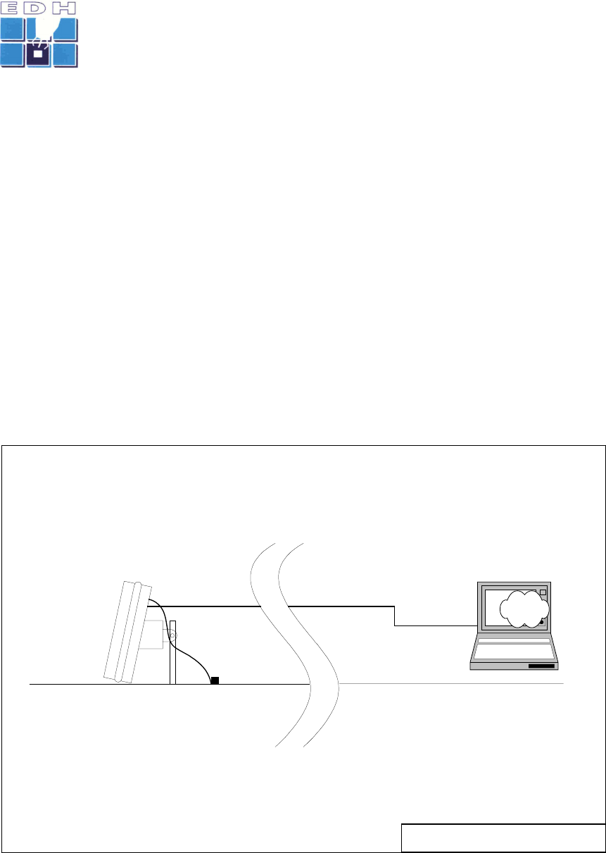
2 SYSTEM DESCRIPTION
The TBox Sensor Unit is a standalone measurement sensor for the detection and
measurement of moving objects in sports applications.
The unit comprises the following main sub-assemblies and/or printed circuit board
assemblies:
• Microwave subassembly, comprising a microstrip microwave antenna array with
integrated transmitter and receiver circuits
• DC/Video printed circuit board assembly
• Digital processor printed circuit board assembly
• Mains power supply module
• User interface software (PC based)
• Mains power cable
• Data interface cable
The following diagram depicts the TBox Sensor Unit:
TBOX System Block Diagram Issue A
20 January 2003
Copyright EDH (South Africa) (Pty) Ltd
Host Computer
RS-422 Data
Interface
TBOX
Sensor Unit
Main Power Supply
(100 - 240VAC 50/60Hz)
TBOX
Software
(Main.exe)
RS-422 Data
Interface
Figure 1 – System Block Diagram

TBox Installation and Operating Manual A
______________________________________________________________________________________________
page 6 of 6
Issue A
3 INSTALLATION
This section explains how to install, interconnect and set up the system.
3.1 MOUNTING AND ALIGNMENT
The TBox Sensor Unit is intended to be floor mounted, using the mounting bracket and
accessories supplied. The Unit should be installed on a hard, level horizontal surface.
The Sensor is fastened to the surface by means of the mounting rod attached to the
mounting bracket on the rear of the Sensor Unit.
While the rod must be anchored using an appropriately secure anchor or pivot, the
Sensor body must be free-standing on the floor surface, to enable it to be aligned and
pointed in the desired direction.
Once the Sensor has been anchored to the mounting rod, it must be roughly pointed in
the desired direction, being perpendicular to the front face of the Unit.
If necessary, corrections must be made to the mounting anchor/pivot as well as the
body of the Sensor Unit to ensure that it is level relative to the horizontal plane. Where
necessary, spacers may be placed under the sensor unit to eliminate uneven floor
characteristics. The integral bubble spirit level on the mounting block can be used to
verify the installation.
Once the sensor is aligned horizontally, the pointing direction must be finally adjusted,
ensuring that the pointing direction is to within ± 2 degrees of the desired direction.
Finally, secure the mounting rod anchor fasteners and mounting bracket bolts.
3.2 DATA CONNECTIONS
The data interface to the host computer is a balanced, asynchronous serial data
interface compliant with RS-422 standard specifications.
Identify the data interface connector (9 pin D-style) on the rear panel of the Sensor
Unit.
Attach the host computer to the Sensor Unit, using the supplied data interface cable.
3.3 SWITCHING ON
Identify the mains power connector (3 pole Powercon) on the rear panel.
Attach the mains power to the Sensor Unit, using the supplied mains power cable.
Ensure that the mains power supplies connected are correct (AC) and that the voltages
are to specification (100-240 Vac, 50/60Hz, 30VA).
Switch on the Sensor Unit.
The system is now ready for use.

TBox Installation and Operating Manual A
______________________________________________________________________________________________
page 7 of 7
Issue A
4 TBOX SOFTWARE
4.1 DESCRIPTION
The TBox Software is a computer program that provides the user interface to the
Sensor Unit.
The TBox Software enables the user to:
• Make/change Sensor settings
• View measured speed and ancillary data
4.2 SOFTWARE INSTALLATION
4.2.1 Host computer requirements
The Host Computer should have the following minimum specifications:
System Processor Intel Pentium III, 500 MHz or more
Memory 128 Mbytes or more
Display 800 x 600 or 1024 x 768 pixels, color
Hard Disk Drive 4 Gbyte or more
CD ROM Drive Optional
Flexible Disk Drive 1.44 Mbyte – required
Operating system Windows 2000, NT 4, Windows 98, or Windows
XP
Mouse and keyboard Required
USB interface port Optional
4.2.2 Installation of software
The TBox Software is automatically installed on the host PC from either the 1.44 Mbyte
flexible Diskette or CD ROM media supplied.
The software is supplied on both 1.44 Mbyte flexible disk and CD formats, and can be
installed on the host PC without the rest of the system connected.
1) Insert flexible diskette into 1.44 Mbyte diskette drive (alternatively, insert CD
into CD drive)
2) Run the
setup.exe application from the selected drive
oExamples: A:setup.exe (for a diskette in drive A:) or D:setup.exe (for a
CD in drive D: )
3) Follow the installation instructions
4) When the program files are successfully installed, press the “Finish” button.
4.2.3 Operation
Run the application in Windows, by selecting START > PROGRAMS > EDH > main.exe
TBox Installation and Operating Manual A
______________________________________________________________________________________________
page 8 of 8
Issue A
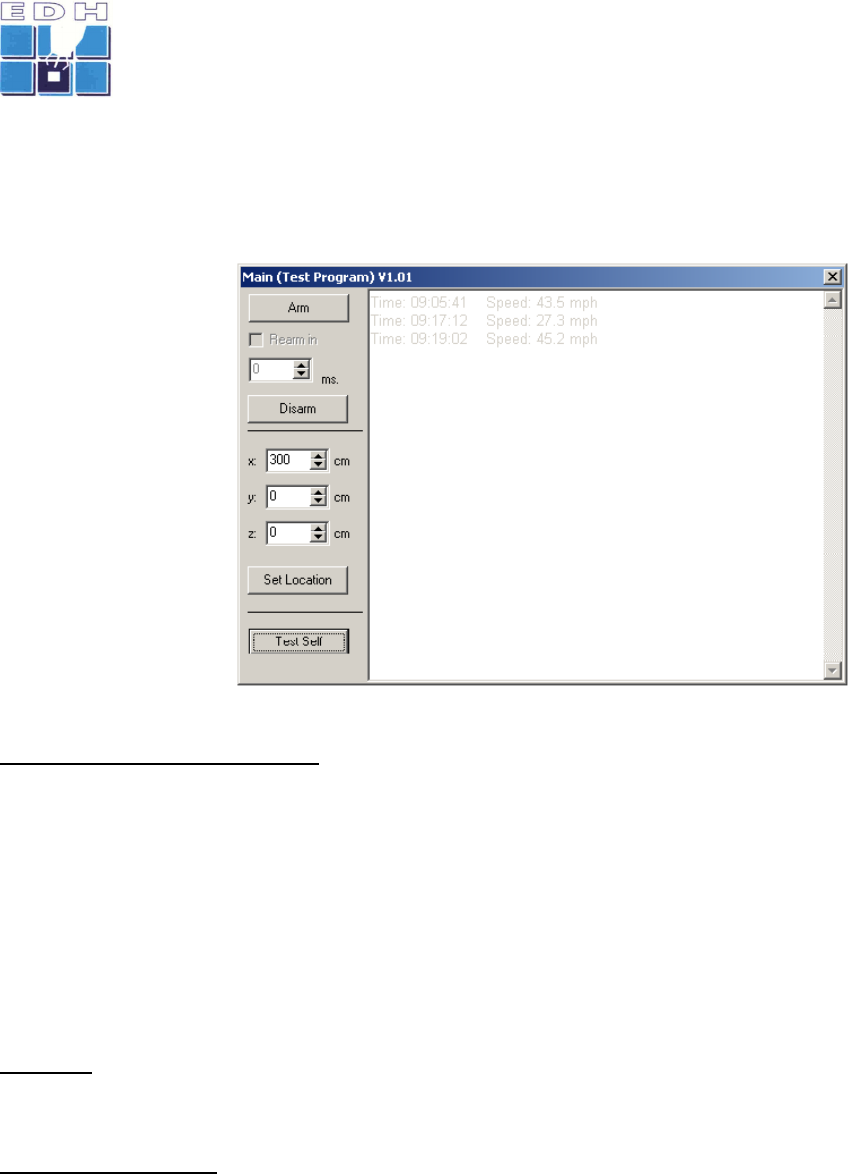
5 USING THE SYSTEM
Once the setup steps as described in the previous section have been performed, the
user may proceed with measurements.
First, ensure that the TBox Sensor Unit is switched on, and connected to the Host PC.
Run the host
computer software
application
main.exe. The
user screen will
display the required
controls and settings,
as well as the log of
speed
measurements.
The primary
functions available to
the user are:
View/set the sensor location
The location of the sensor relative to the measured event can be set, in three
dimensions (x,y,z). Negative values may be selected. The notation for location settings
is as follows:
x : positive distance along the pointing direction of the Sensor
y : offset perpendicular to the pointing line of the sensor.
+ for Right offsets and – for Left offsets
z : vertical offset between the object and the Sensor Unit
+ for Sensor lower than object, - otherwise
Self test
Selecting this function will perform a self test of the TBox Sensor Unit, providing a
Go/NoGo indication of the basic functional operation of the Unit.
Arm/Disarm sensor
The sensor can be manually armed by clicking on the Arm button. This will cause the
sensor unit to transmit a microwave signal and anticipate a trigger event (such as rapid
object movement). When the Sensor detects a suitable moving object, it will process
the measured signals to produce a speed value for the detected object. The speed
data will be sent to the TBox Software for display.
The unit can also be set to automatically re-arm after the re-arm delay (in
milliseconds).
Once armed, the sensor can be disarmed by selecting the Disarm button.

TBox Installation and Operating Manual A
______________________________________________________________________________________________
page 9 of 9
Issue A
Speed log display
Each speed measurement received from the TBox Sensor will be displayed on the log
screen, with the time at which it was measured.

TBox Installation and Operating Manual A
______________________________________________________________________________________________
page 10 of 10
Issue A
6 MAINTENANCE AND TROUBLESHOOTING
6.1 INTRODUCTION
The Sensor Unit and its associated software is supplied on the strict condition that all
rights relating to trademarks, copyright, patents and designs are reserved by EDH and
may not be reproduced or used in any manner not authorized in writing by EDH.
6.2 MAINTAINING THE SENSOR
The TBox Sensor system is a highly reliable electronic system that requires low
maintenance.
6.2.1 Routine maintenance
Routine maintenance is limited to the following:
• Keep dry and clean at all times
• Cleaning periodically using a damp cloth with, if required, a light household
detergent and water to remove visible soiling
• Inspect the Unit enclosure as well as cable connections periodically for visible
signs of damage or wear
These tasks should be performed by the operator/end user three-monthly (or more
regularly where high levels of dust or mechanical effects (vibration, handling, etc) are
present).
6.2.2 Corrective maintenance
The Sensor Unit is only factory repairable. Faulty units must be swapped with
replacement units.
6.2.3 General maintenance actions
6.2.3.1 Storage
When not in use, store the equipment in its transport packaging.
6.2.3.2 Connectors
Ensure that the connectors are clean and dry at all times. Exposed connectors should
always be protected from dust, moisture, insects and other contaminants.
6.2.3.3 Power supply
Please observe the voltage levels on any external supply, BEFORE applying the power
to the system.
6.2.3.4 Data connector
The data interface connector is a 10 pin ITT Cannon connector fitted to its rear panel.
This connector should be kept dry and free from contamination.
If used continuously for prolonged periods, the cable may be attached and the
connector covered with a self-vulcanizing sealing tape.

TBox Installation and Operating Manual A
______________________________________________________________________________________________
page 11 of 11
Issue A
6.3 TROUBLESHOOTING
Symptom Sensor Unit does not power up
Step 1 Check external supply connections and presence of mains supply to Sensor
Unit
Step 2 Remove Sensor Unit and return for repair
Symptom No Communication between PC and Sensor Unit
Step 1 Check communications cable connection between PC and Sensor
Step 2 Check selection of correct COM” port on TBox Software
Step 3 Restart the PC and the TBox Software
Step 4 Exit the TBox Software program and restart the computer
Step 5 Remove Sensor Unit and return for repair
Symptom No measurements obtained on live objects
Step 1 Ensure Sensor Unit has mains power supply and is switched on
Step 2 Inspect the Sensor Unit to ensure that its mechanically mounting and
alignment is correct
Step 3 Review all settings in the TBox Software, ensuring that the settings and
selections are sensible
Step 4 Inspect data interface connection
Step 5 Remove Sensor Unit and return for repair
Symptom Results appear incorrect
Step 1 Run the Self Test command from the TBox Software
Step 2 Carefully review all settings in the TBox Software, ensuring that the settings
are sensible. Refer to recorded settings used when setting up initially.
Step 3 Change settings in the TBox Software and re-measure objects
6.4 CABLE INSPECTIONS
6.4.1 Data interface cable
Do continuity test between the connectors of the cable roll.
Test for short circuit between all pins on each of the connectors of the cable.

TBox Installation and Operating Manual A
______________________________________________________________________________________________
page 12 of 12
Issue A
7 SPECIFICATIONS
Operating Frequency 10.525.GHz
Transmitter power 10 mW
Antenna gain 17 dB
Horizontal beamwidth 10 degrees
Vertical beamwidth 20 degrees
Dimensions Width 13.8” (350 mm)
Height 10.6” (270 mm)
Thickness 3.9” (100 mm)
Mass < 4.4 lb (2 kg)
Mains power supply 100 – 240 Vac, 50/60 Hz, 1.2A max
Data interface RS-422 asynchronous serial

TBox Installation and Operating Manual A
______________________________________________________________________________________________
page 13 of 13
Issue A
8 INDEX
Alignment......................................... 11
Antenna ............................................. 5
Antenna gain.................................... 12
Arming............................................... 8
CD..................................................... 7
Copyright ......................................... 10
Corrective Maintenance ..................... 10
Data connections ................................ 6
Data interface................................... 12
Dimensions ...................................... 12
Disarming........................................... 8
General Maintenance Actions ............. 10
Horizontal beamwidth........................ 12
Host Computer ................................... 7
Host PC.............................................. 8
Installation ......................................... 6
Installation of Software ....................... 7
Left offsets......................................... 8
Main.exe ............................................ 8
Mains power supply .......................... 12
Maintenance..................................... 10
Mass................................................ 12
Measurements .................................... 8
Memory ............................................. 7
Mounting............................................ 6
Operating frequency ......................... 12
Operating system................................ 7
Patents ............................................ 10
Pointing.............................................. 8
Pointing.............................................. 6
Power .............................................. 12
Power Supply.................................... 10
Re-arm delay ...................................... 8
Right offsets ....................................... 8
Routine maintenance......................... 10
RS-422 ......................................... 6, 12
Self test.............................................. 8
Sensor location ................................... 8
Sensor settings ................................... 7
Serial data interface ............................6
Settings............................................ 11
Setup.exe ........................................... 7
Speed ................................................8
Spirit level .......................................... 6
Storage ............................................ 10
Switching on....................................... 6
System Description.............................. 5
Tbox Software .................................... 7
Trademarks ...................................... 10
Transmitter....................................... 12
Trigger ............................................... 8
Troubleshooting ...........................10, 11
User interface software........................ 5
Vertical beamwidth............................ 12
Vertical offset ..................................... 8
Voltages ............................................. 6