Flir BelgiumBA AD2D-8P Light marine navigational radar User Manual 81256 3

Raymarine UK Ltd. Light marine navigational radar 81256 3

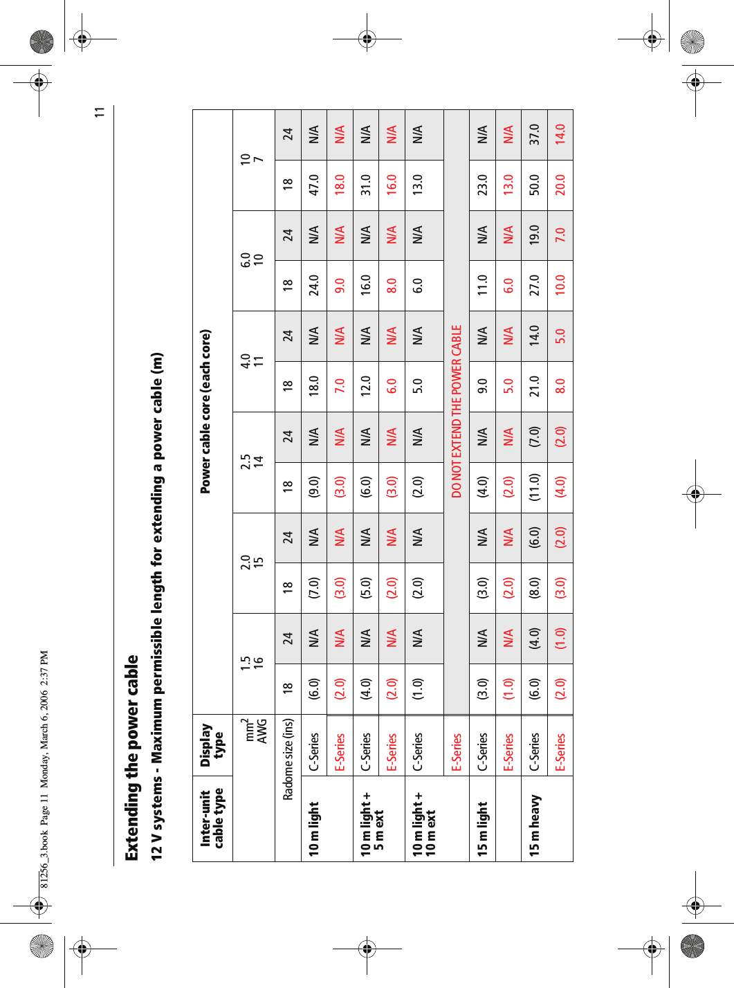
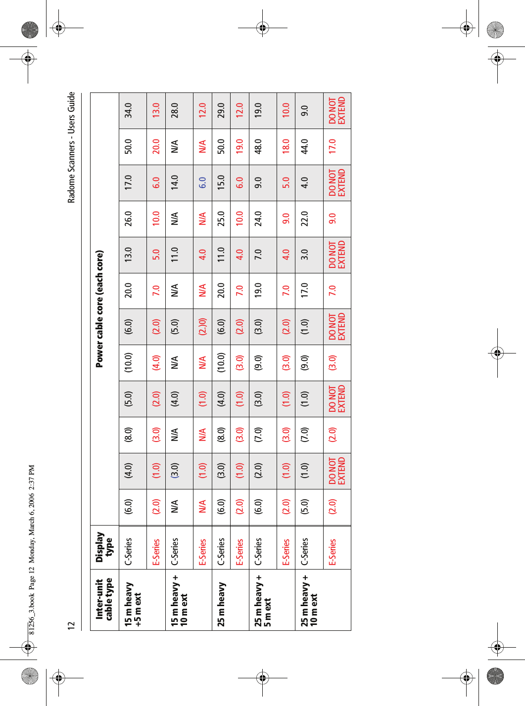
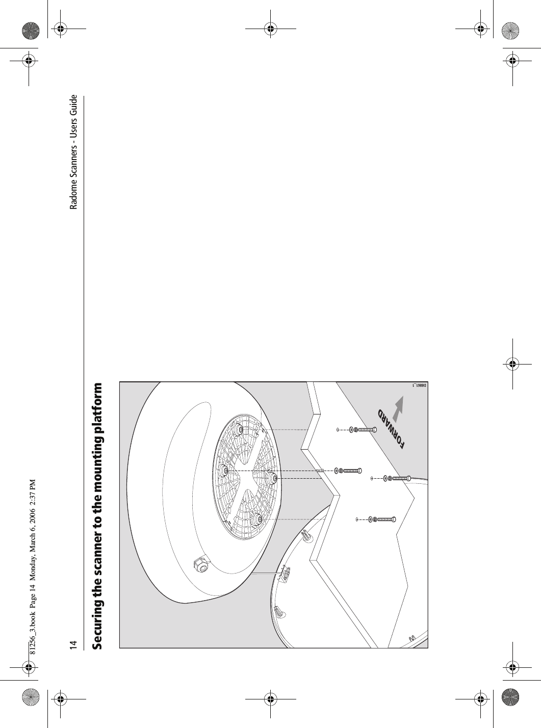
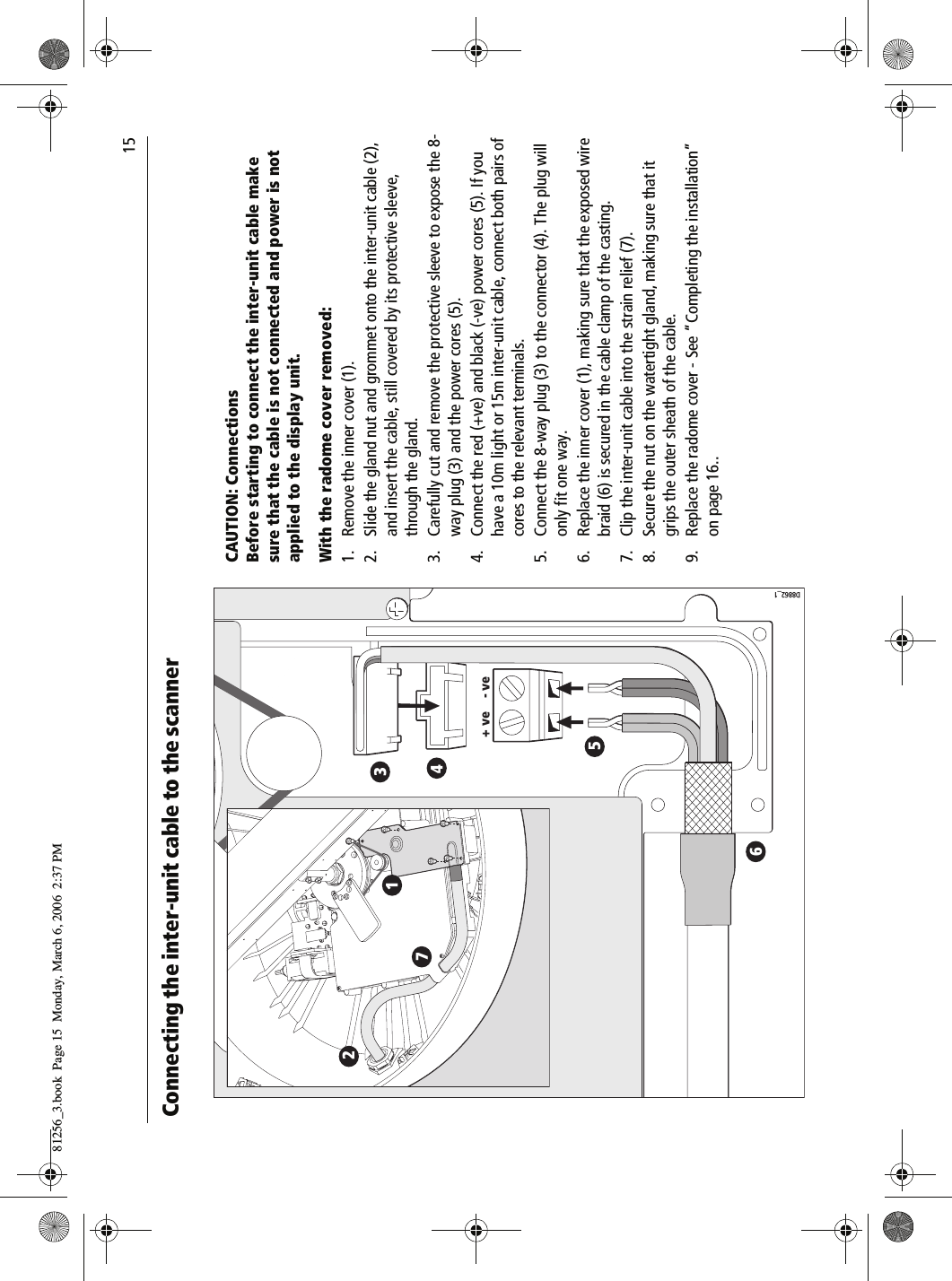
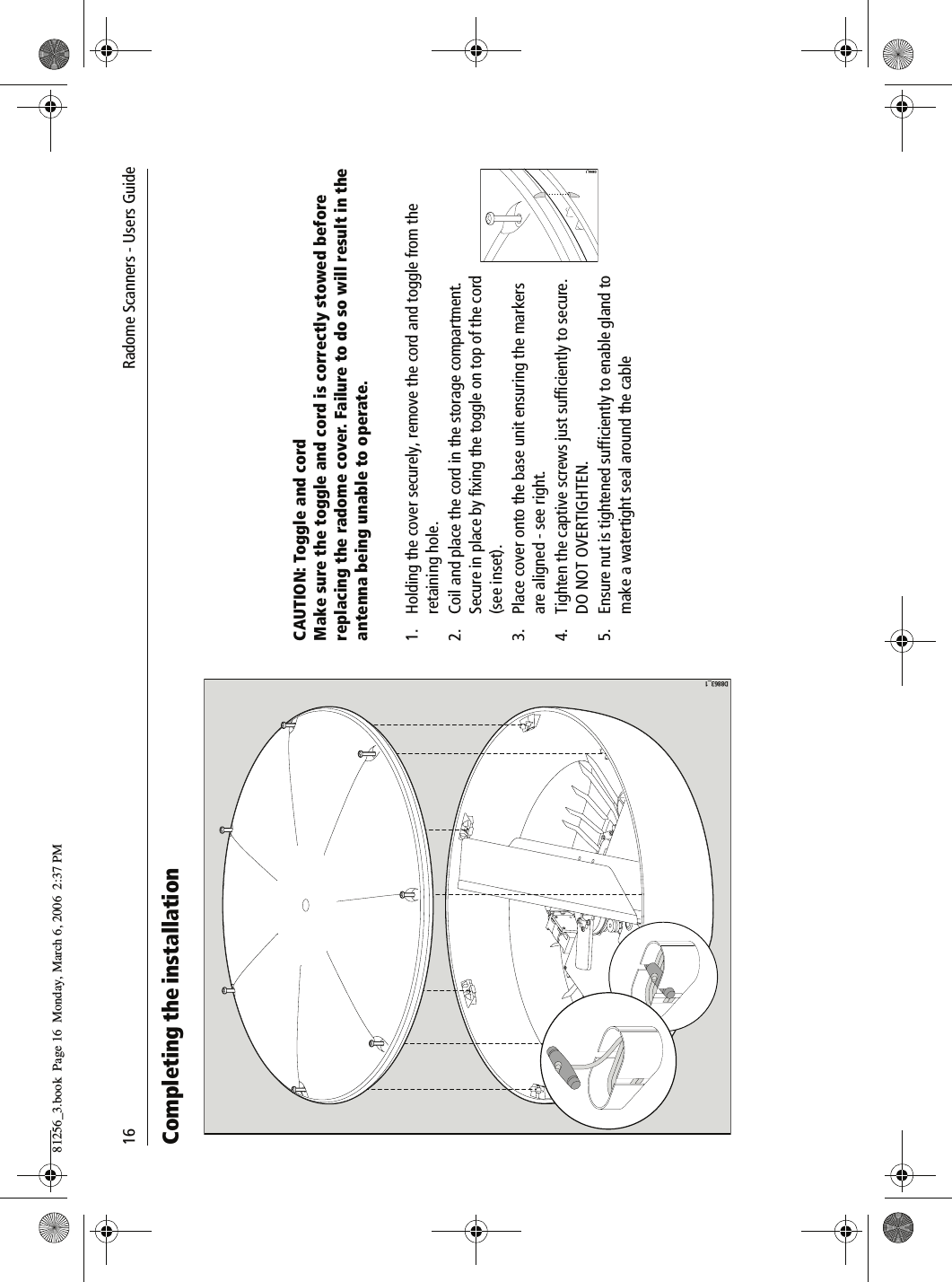
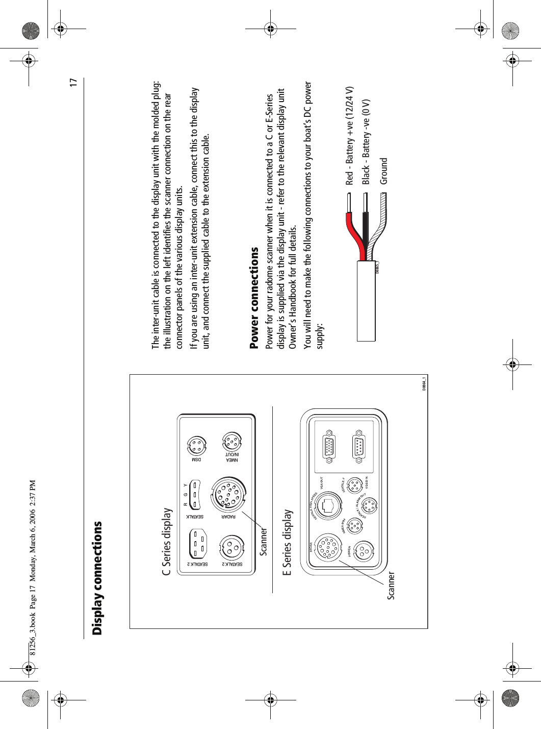
Radome scanners user guide

 Radome Scanners Users Guide     Document Number: 81256_3     Date: March 200681256_3.book  Page 1  Monday, March 6, 2006  2:37 PM
Trademarks and registered trademarksAutohelm, HSB, Raymarine, RayTech, RayTech RNS, Sail Pilot, SeaTalk and Sportpilot are registered trademarks of Raymarine Limited. Apelco is a registered trademark of Raymarine Holdings Limited (Registered in all major marketing territories).AST, Autoadapt, Auto GST, Autoseastate, Autotrim, Bidata, Marine Intelli-gence, Maxiview, On Board, Raychart, Raynav, Raypilot, Raystar, ST40, ST60, Seaclutter, Smart Route, Tridata and Waypoint Navigation are trade-marks of Raymarine Limited.All other product names mentioned are trademarks or registered trade-marks (if applicable) of their respective companies.© Raymarine UK Ltd 200681256_3.book  Page 2  Monday, March 6, 2006  2:37 PM
 Contents                              iContentsImportant information ................................................................1Introduction........................................................................................... 1Intended use ......................................................................................... 1Safety notices........................................................................................ 1WARNING: High voltage............................................................1WARNING: Electromagnetic energy........................................1WARNING: Product installation ...............................................1Waste Electrical and Electronic Directive............................................... 2EMC conformance ................................................................................. 2Declaration of conformity...................................................................... 2Display software version ....................................................................... 2Warranty ............................................................................................... 2Handbook information .......................................................................... 2Installation ....................................................................................3EMC installation guidelines................................................................... 3Suppression ferrite............................................................................. 3Connections to other equipment .......................................................  3What’s in the box? ................................................................................ 4What tools do I need to install the scanner? .....................................  4How big is the scanner? ........................................................................ 518” Radome scanner.........................................................................  524” Radome scanner.........................................................................  5Planning the installation ....................................................................... 6Cable requirements ............................................................................... 7Scanner cables ...................................................................................... 7Running the cable to the scanner ......................................................  7Inter-unit cables.................................................................................  7Power cables ......................................................................................... 8Extending the power cable ................................................................ 8Power requirements........................................................................... 8Extending the power cable....................................................................9Mounting options................................................................................11Preparing the mounting holes .............................................................11Securing the scanner to the mounting platform ..................................12Connecting the inter-unit cable to the scanner ...................................13Completing the installation .................................................................14Display connections.............................................................................15Power connections........................................................................... 15Inter-unit cable connections ............................................................ 16Scanner setup......................................................................................16Before you go to sea........................................................................ 16EMC conformance............................................................................ 16System checks.................................................................................. 16Set up, alignment and timing checks............................................... 17Maintenance and troubleshooting .......................................... 19Introduction ..................................................................................... 19Maintenance.................................................................................... 19Troubleshooting............................................................................... 19Technical support............................................................................. 20Technical specification.............................................................. 21RD218 18”Radome scanner unit  ........................................................ 21RD424 24”Radome scanner unit  ........................................................ 23Raymarine World Wide Warranty  ............................................2581256_3.book  Page i  Monday, March 6, 2006  2:37 PM
ii        Radome Scanners - Users Guide81256_3.book  Page ii  Monday, March 6, 2006  2:37 PM
 Important information                              1Important informationIntroductionThis handbook contains an explanation of how to install, connect andmaintain your radome scanner and covers the following models:• RD218 - 18” 2kW Radome scanner.• RD424 - 24” 4 kW Radome scanner.Your radar has been designed and manufactured to meet the rigorousdemands of the marine environment. However, no machine can perform itsintended function unless installed, operated and maintained properly.Please carefully read and follow the recommended procedures for installa-tion contained in this handbook.When properly installed and operated, the use of this radar will conform tothe requirements of:• IEEE C95.1 - 1999 - Standard for Safety Levels with respect to HumanExposure to Radio Frequency Electromagnetic Fields, 3 kHz to 300GHz.• ICNIRP Guidelines 1998 - International Commission on Non-IonisingRadiation Protection: Guidelines for limiting exposure to time-varyingelectric, magnetic and electro-magnetic fields (up to 300GHz) 1998.Intended useThis product is a radar scanner intended for use within a navigational radarsystem. The intended application is for leisure marine boats and workboats not covered by IMO/SOLAS carriage requirements.Safety notices                    WARNINGRadio Frequency Radiation HazardThe radar antenna emits electromagnetic radio frequency (RF) energy which can be harmful particularly to your eyes. DO NOT look at the antenna at close range. It is important that the radar is turned off whenever personnel are required to come close to the scanner assembly or associated equipment. It is recommeded that the radar scanner is mounted out of range of personnel (above head height).Distances from the face of the radar at which RF radiation levels of 100 W/m2 and 10 W/m2 exist are given belowModel Distance to 100 W/m2 pointDistance to 10 W/m2 pointRD218 Nil Worst case 1.0mRD214 Nil Worst case 1.0m81256_3.book  Page 1  Monday, March 6, 2006  2:37 PM
2     Radome Scanners  - Users GuideFCC NoticeChanges or modifications to this equipment, not expressly approved in writing by Raymarine Inc., could violate compli-ance withFCC rules and void the operator’s authority to operate the equipment.Waste Electrical and Electronic EquipmentDirective          The Waste Electrical and Electronic Equipment (WEEE) Direc-tive requires the recycling of waste electrical and electronicequipment. Whilst the WEEE Directive does not apply to someof Raymarine’s products, we support its policy and ask you tobe aware of how to dispose of this product.The crossed out wheelie bin symbol, illustrated above, and found on ourproducts signifies that this product should not be disposed of in generalwaste or landfill.Please contact your local dealer, national distributor or Raymarine Tech-nical Services for information on product disposal.EMC conformance All Raymarine equipment and accessories are designed to the best industrystandards for use in the recreational marine environment. The design andmanufacture of Raymarine equipment and accessories conform to theappropriate Electromagnetic Compatibility (EMC) standards, but correctinstallation is required to ensure that performance is not compromised.Declaration of conformityRaymarine UK Limited hereby declare that the products to which thismanual relates comply with the appropriate requirements and provisionsof the R&TTE Directive 1999/5/EC.The full Declaration of Conformity may be viewed on the relevant product pages at www.raymarine.com          WARNINGHigh VoltageThe scanner unit contains high voltages. Adjustments require specialized service procedures and tools only avail-able to qualified service technicians - there are no user serviceable parts or adjustments. The operator should never remove the scanner unit internal covers or attempt to sevice the equipment.          WARNINGProduct installationThis equipment must be installed in accordance with the instructions contained in this handbook. Failure to do so could result in poor product performance, personal injury and/or damage to your boat.81256_3.book  Page 2  Monday, March 6, 2006  2:37 PM
 Important information                              3Display software versionFor operation of your scanner, the display unit requires the appropriatesoftware version.  These are:• E Series displays - Version 3.03 or later.• C Series displays - Version 3.01 or later.The software version can be confirmed by switching on the display andchecking the version number during the magnetron warm-up sequence.However, if a scanner is not connected to the display, the version numberwill only be displayed for 10 seconds.WarrantyTo register your new Raymarine product, please take a few minutes to fillout the warranty card. It is important that you complete the owner infor-mation and return the card to receive full warranty benefits. Alternativelyyou can register your product on line at www.raymarine.comHandbook informationThe technical and graphical information contained in this handbook, to thebest of our knowledge, was correct as it went to press. However, our policyof continuous improvement and updating may change product specifica-tions without prior notice. As a result, unavoidable differences between theproduct and handbook may occur from time to time.81256_3.book  Page 3  Monday, March 6, 2006  2:37 PM
4     Radome Scanners  - Users Guide81256_3.book  Page 4  Monday, March 6, 2006  2:37 PM
 Installation                              5InstallationEMC installation guidelinesAll Raymarine equipment and accessories are designed to the best industrystandards for use in the recreational marine environment.Their design and manufacture conforms to the appropriate ElectromagneticCompatibility (EMC) standards, but correct  installation is required toensure that performance is not compromised. Although every effort hasbeen taken to ensure that they will perform under all conditions, it isimportant to understand what facts could affect the operation of theproduct.The guidelines here describe the conditions for optimum EMC performance,but it is recognized that it may not be possible to meet all of these condi-tions in all situations. To ensure the best possible conditions for EMCperformance within the constraints imposed by any location, always ensurethe maximum separation possible between different items of electricalequipment.For optimum EMC performance, it is recommended wherever possible:• Raymarine equipment and cables connected to it are:• At least 3 ft. (1m) from any other equipment transmitting orcarrying radio signals. In the case of Single Side Band (SSB) radio,the distance should be increased to 7 ft. (2m).• More than 7 ft. (2m) from the path of a radar beam. A radar beamcan normally be assumed to spread 20 degrees above and belowthe radiating element.• The equipment is supplied from a separate battery to that used forengine start. Voltage drops below 10 V, and starter motor transients,can cause the equipment to reset. This will not damage the equipment,but may cause the loss of some information and may change the oper-ating mode.• Raymarine specified cables are used. Cutting and rejoining thesecables can compromise EMC performance and must be avoided unlessdoing so is detailed in the installation manual/Suppression ferriteIf a suppression ferrite is attached to a cable, thisferrite should not be removed. If the ferrite needs tobe removed during installation it must be reassem-bled in the same position.The illustration shows typical cable suppressionferrites used with Raymarine equipment. Alwaysuse the ferrites supplied by Raymarine.Connections to other equipmentIf your Raymarine equipment is to be connected to other equipment using acable not supplied by Raymarine, a suppression ferrite MUST always beattached to the cable near to the Raymarine unit.D8852_181256_3.book  Page 5  Monday, March 6, 2006  2:37 PM
6             Radome Scanners - Users GuideWhat’s in the box?          Components are dependant on your system package, but are either:• 18” 2 kW Radome scanner and 15 m light cable, or• 24” 4 kW Radome scanner and 15 m heavy cable.• Fixing bolts and washers.•Grease.• Handbook.What tools do I need to install the scanner?          Radome ScannerInter-unit cableInstallation templateD8853_1Drill 4 holes, 10 mm diameter(18'' and 24'' Radomes)141.5 mm27.5 mm18'' or 24'' NGS RadomeMounting TemplateCenter Line of Radome3026-136-AArtwork Number 3032-866-ACenter Line of RadomeForward233 mmGreaseFixing bolts and washers X4DrillAdhesive tape10 mm  drill bit13 mm socketTorque  wrenchPhilips screwdriverD8854_181256_3.book  Page 6  Monday, March 6, 2006  2:37 PM
 Installation                              7How big is the scanner?18” Radome scanner          24” Radome scanner          346 mm (13.62 in)diameter521 mm (20.5 in)diameter233 mm(9.17 in)D8566-1247 mm (9.7 in)116.5 mm(4.58 in)141.5 mm(5.57 in)27.5 mm(0.92 in)D8567-1 247 mm (9.7 in)233 mm(9.17 in)116.5 mm(4.58 in)141.5 mm(5.57 in)27.5 mm(1.08 in)346 mm (13.62 in)diameter652 mm (25.67 in)diameter81256_3.book  Page 7  Monday, March 6, 2006  2:37 PM
8             Radome Scanners - Users GuidePlanning the installation          Mount the scanner as high as possible above the waterline for better long range performance, but make sure it:• is above head height.• is easily accessible.• is as near to the boat’s centerline as possible.• is on a rigid and stable platform.• is clear of large objects such as the flybridge, large engine stacks, searchlights, horns or masts.• is clear of heat and fumes.• is at least 1 m away from a magnetic compass or other equipment antenna.Don’t put the scanner so high, that it is affected by the pitching and rolling of the boat.          Mount the scanner so that the array rotates parallel to the waterline.The radar beam is approximately 25o wide in the vertical direction, giving good target detection when your boat pitches and rolls.           Planing hull and some displace-ment hull boats adopt a higher bow angle when the boat is at cruising speed., giving poor target detection. It may be neces-sary to lower the radar beam back towards the parallel, by shimming the rear of the radar, so that the beam points slightly down when the boat is at rest.D8855_112.5˚12.5˚D8856_1Wedge orwashersForwardD8857_181256_3.book  Page 8  Monday, March 6, 2006  2:37 PM
 Installation                              9Cable requirementsYou need to consider the following points before installing the system cables:• You need to connect the scanner to the display unit and power. The cable required will depend on the display unit and scanner type.• All cables should be adequately clamped and protected from physical damage and exposure to heat - avoid running cables through bilges or doorways, or close to moving or hot objects.• Acute bends must be avoided.• Where a cable passes through an exposed bulkhead or deckhead, a watertight gland or swan neck tube should be used.• Avoid cutting and rejoining cables. If this cannot be avoided refer to Extending the power cable on page -11.Scanner cablesA radome scanner connected to a C or E-Series display receives power via the display unit. Running the cable to the scannerDO NOT pull the cable through bulkheads using a cord attached to the connector. This could damage the connections.The cable entrance is at the rear of the scanner unit. If the unit is mounted on a hollow mast, the cable may be run inside the mast and fed though the unit’s cable entrance. Make sure that the cable does not chafe where it enters and exits the mast.To minimize electrical interference try to avoid running radar cables near other on board electrical equipment. It is also good practice to avoid running radar cables in parallel with power cables.Inter-unit cablesThe inter-unit cable, illustrated below, is fitted with an 8-way plug and power cores (covered with a clear protective sleeve) for connecting to the scanner.          The length of the cable supplied should be sufficient to complete the cable run on most small boats. For longer runs, additional or replacement cables are available. These cables have four power cores to minimize voltage drops over the longer cable run.Optional cable lengths available are:• Part No. M92668 - 15 m heavy extension cable.• Part No. M92669 - 25 m heavy replacement cable.The maximum inter-unit cable length is limited by the minimum supply voltage, the scanner type (18” or 24 “radome), and the cable type (2 or 4 power cores).For boats with 12 V DC power systems details of recommended cable(s) for different run lengths can be found in Extending the power cable on page -11.Boats with 24 V DC power systems can use any combination of inter-unit cables.To display or extension(power supplied via display unit) To Radome ScannerD8858_181256_3.book  Page 9  Monday, March 6, 2006  2:37 PM
10              Radome Scanners - Users GuidePower cablesRadome radar systems are intended for use on boat’s DC power systems operating in the range 10.7 to 32 V DC. That is 12 V and 24 V systems, they should not be used on 32 V systems.A 1.5 m (5ft) power cable is supplied with the display unit for connecting the boat’s DC power to the radar scanner via the display unit.Refer to the relevant display unit handbook for details on connecting this cable.Extending the power cable24 V power systemsIf your boat has a 24 V power system, the power cable may be extended by up to 20 m using a wire gauge of 1.5 mm2 (AWG 16) or greater, irrespec-tive of the inter-unit cable length.12 V power systemsIf your boat has a 12 V power system, longer power cable runs may require larger wire gauges to minimize any voltage drop in the cable. For full details on extending the power cable and maximum permissible lengths refer to Extending the power cable on page -11.Power requirementsThis radar is not recommended for use on ‘positive’ ground boats. The power cable earth screen must be connected to the boat’s ground.The boat’s power system should be either:• Negative grounded, with the negative battery terminal connected to the boat’s ground, or,• Floating with neither battery terminal connected to the boat’s ground.Radome scanners receive power from the display via the inter-unit cable. The display power cable is supplied with the display unit and details for connecting power are detailed in the relevant Owner’s handbook.Grounding the radar systemIt is important that an effective radio frequency (RF) ground is connected to the radar system.You must ground the radar by connecting the drain wire (screen) of the power cable to the nearest ground point of your boat’s RF ground system. Full details can be found in the Owner’s Handbook for your display unit.If you need to extend the wire, the extension wire should be an 8 mm braid or 6 mm2 (AWG 10) multi-strand cable.If your boat does not have an RF system, connect the drain wire to the negative battery terminal.81256_3.book  Page 10  Monday, March 6, 2006  2:37 PM
                               11Extending the power cable12 V systems - Maximum permissible length for extending a power cable (m)Inter-unit cable typeDisplay typePower cable core (each core)mm2AWG1.516 2.015 2.514 4.011 6.010 107Radome size (ins) 18 24 18 24 18 24 18 24 18 24 18 2410 m light C-Series (6.0) N/A (7.0) N/A (9.0) N/A 18.0 N/A 24.0 N/A 47.0 N/AE-Series (2.0) N/A (3.0) N/A (3.0) N/A 7.0 N/A 9.0 N/A 18.0 N/A10 m light + 5 m extC-Series (4.0) N/A (5.0) N/A (6.0) N/A 12.0 N/A 16.0 N/A 31.0 N/AE-Series (2.0) N/A (2.0) N/A (3.0) N/A 6.0 N/A 8.0 N/A 16.0 N/A10 m light + 10 m extC-Series (1.0) N/A (2.0) N/A (2.0) N/A 5.0 N/A 6.0 N/A 13.0 N/AE-Series DO NOT EXTEND THE POWER CABLE15 m light C-Series (3.0) N/A (3.0) N/A (4.0) N/A 9.0 N/A 11.0 N/A 23.0 N/AE-Series (1.0) N/A (2.0) N/A (2.0) N/A 5.0 N/A 6.0 N/A 13.0 N/A15 m heavy C-Series (6.0) (4.0) (8.0) (6.0) (11.0) (7.0) 21.0 14.0 27.0 19.0 50.0 37.0E-Series (2.0) (1.0) (3.0) (2.0) (4.0) (2.0) 8.0 5.0 10.0 7.0 20.0 14.081256_3.book  Page 11  Monday, March 6, 2006  2:37 PM
12               Radome Scanners - Users Guide15 m heavy +5 m extC-Series (6.0) (4.0) (8.0) (5.0) (10.0) (6.0) 20.0 13.0 26.0 17.0 50.0 34.0E-Series (2.0) (1.0) (3.0) (2.0) (4.0) (2.0) 7.0 5.0 10.0 6.0 20.0 13.015 m heavy + 10 m extC-Series N/A (3.0) N/A (4.0) N/A (5.0) N/A 11.0 N/A 14.0 N/A 28.0E-Series N/A (1.0) N/A (1.0) N/A (2.)0) N/A 4.0 N/A 6.0 N/A 12.025 m heavy C-Series (6.0) (3.0) (8.0) (4.0) (10.0) (6.0) 20.0 11.0 25.0 15.0 50.0 29.0E-Series (2.0) (1.0) (3.0) (1.0) (3.0) (2.0) 7.0 4.0 10.0 6.0 19.0 12.025 m heavy + 5 m extC-Series (6.0) (2.0) (7.0) (3.0) (9.0) (3.0) 19.0 7.0 24.0 9.0 48.0 19.0E-Series (2.0) (1.0) (3.0) (1.0) (3.0) (2.0) 7.0 4.0 9.0 5.0 18.0 10.025 m heavy + 10 m extC-Series (5.0) (1.0) (7.0) (1.0) (9.0) (1.0) 17.0 3.0 22.0 4.0 44.0 9.0E-Series (2.0) DO NOT EXTEND (2.0) DO NOT EXTEND (3.0) DO NOT EXTEND 7.0 DO NOT EXTEND 9.0 DO NOT EXTEND 17.0 DO NOT EXTENDInter-unit cable typeDisplay typePower cable core (each core)81256_3.book  Page 12  Monday, March 6, 2006  2:37 PM
                               13Mounting options          Preparing the mounting holes          Mounting platformMounting platformFORWARDFORWARD12D8859_1AMounting platformD8860_1IMPORTANTEnsure mounting platform is adequately robust for this installation.FORWARD121. Tape template to mounting  platform.2. Using template, drill 10 mm   diameter hole in 4 positions. Drill 4 holes, 10 mm diameter(18'' and 24'' Radomes)141.5 mm27.5 mm233 mm18'' or 24'' NGS RadomeMounting TemplateCenter Line of Radome3026-136-AArtwork Number 3032-866-ACenter Line of RadomeForwar d81256_3.book  Page 13  Monday, March 6, 2006  2:37 PM
14               Radome Scanners - Users GuideSecuring the scanner to the mounting platform          FORWARDD8861_181256_3.book  Page 14  Monday, March 6, 2006  2:37 PM
                               15Connecting the inter-unit cable to the scanner          D8862_11234567+ ve - veCAUTION: ConnectionsBefore starting to connect the inter-unit cable make sure that the cable is not connected and power is not applied to the display unit.With the radome cover removed:1. Remove the inner cover (1).2. Slide the gland nut and grommet onto the inter-unit cable (2), and insert the cable, still covered by its protective sleeve, through the gland.3. Carefully cut and remove the protective sleeve to expose the 8-way plug (3) and the power cores (5).4. Connect the red (+ve) and black (-ve) power cores (5). If you have a 10m light or 15m inter-unit cable, connect both pairs of cores to the relevant terminals.5. Connect the 8-way plug (3) to the connector (4). The plug will only fit one way.6. Replace the inner cover (1), making sure that the exposed wire braid (6) is secured in the cable clamp of the casting.7. Clip the inter-unit cable into the strain relief (7).8. Secure the nut on the watertight gland, making sure that it grips the outer sheath of the cable.9. Replace the radome cover - See “Completing the installation” on page 16..81256_3.book  Page 15  Monday, March 6, 2006  2:37 PM
16               Radome Scanners - Users GuideCompleting the installationCAUTION: Toggle and cordMake sure the toggle and cord is correctly stowed before replacing the radome cover. Failure to do so will result in the antenna being unable to operate.1. Holding the cover securely, remove the cord and toggle from the retaining hole.2. Coil and place the cord in the storage compartment. Secure in place by fixing the toggle on top of the cord (see inset).3. Place cover onto the base unit ensuring the markers are aligned - see right.4. Tighten the captive screws just sufficiently to secure. DO NOT OVERTIGHTEN.5. Ensure nut is tightened sufficiently to enable gland to make a watertight seal around the cableD8863_1D8984_181256_3.book  Page 16  Monday, March 6, 2006  2:37 PM
                               17Display connections          The inter-unit cable is connected to the display unit with the molded plug: the illustration on the left identifies the scanner connection on the rear connector panels of the various display units.If you are using an inter-unit extension cable, connect this to the display unit, and connect the supplied cable to the extension cable.Power connectionsPower for your radome scanner when it is connected to a C or E-Series display is supplied via the display unit - refer to the relevant display unit Owner’s Handbook for full details.You will need to make the following connections to your boat’s DC power supply:          NMEAIN/OUTDSMSEATALKRADARSEATALK 2SEATALK 2RGYScannerC Series displayScannerE Series displayD8864_1Red - Battery +ve (12/24 V)Black - Battery -ve (0 V)GroundD8865_181256_3.book  Page 17  Monday, March 6, 2006  2:37 PM
18               Radome Scanners - Users GuideInter-unit cable connectionsThe illustration below details the connections for the inter-unit cable:          Scanner setupBefore you go to seaAfter you have installed your radar, and before you go to sea, it is impor-tant to check the installation. You can then set up the radar system, align the scanner and check the system timing.Set up, alignment and timing checks are performed from the radar system display unit. The procedures are outlined on this page; full details are avail-able in the relevant display unit Owner’s Handbook. You should read this and familiarize yourself with the operation of the radar.EMC conformanceAlways check the installation before going to sea to make sure that it is not affected by radio transmissions, engine starting, etc.System checks System checkBefore performing any functional tests, make sure:• All securing bolts are fully tightened and mechanical locking devices as specified are in place.• All connections have been made.• All connecting wires are secured and protected as necessary.If you have installed the radar yourself, ask your local Raymarine autho-rized installation dealer to check the installation.123547101186913 12BlackWhiteOrangeBlackBlackGreenYellowShieldRedRedVioletBlueGreyVideoVideo RTN*Battery --veTx Trigger +Battery --veData I/O +Tx Trigger --    Battery +veData I/O --*Battery +veAzimuth +Azimuth -- 1234567    8910111213WhiteBlackOrangeYellowGreenBlueViolet    GreyRedRedBlackBlack 8765432    1VideoVideo RtnTx Trigger +Tx Trigger --Data I/O +Data I/O --Azimuth +    Azimuth --Battery +ve*Battery +ve*Battery --veBattery --ve Not fitted onOpen Array Scanners(refer to Section 2.2)Front view ofDisplay Cable ConnectorFront view of RadomeScanner Cable ConnectorDisplay Scanner* Not present on 'light', 11 core cables.   Battery +ve/--ve = 12 or 24v.D8866_12 14 36 58 781256_3.book  Page 18  Monday, March 6, 2006  2:37 PM
                               19Set up, alignment and timing checksSwitch on and initial set up1. Press and hold the POWER key of the display unit until the unit beeps. The magnetron warm-up sequence should start, after which the unit should enter standby mode.2. If necessary, adjust the lighting and contrast.3. If necessary, change the default language settings.Transmission checkEnsure that all personnel are clear of the scanner and switch to transmit mode. Run through the radar operations as described in the relevant display unit’s Owner’s Handbook and check that all the expected data is displayed.Bearing alignmentWith the system correctly installed, check the bearing alignment to ensure that targets appear at their correct bearing relative to the boat’s bow. Adjust the alignment as necessary.Display timing adjustmentThe display timing can be affected by the length of cable used to connect the scanner to the display unit. This in turn affects the short range accuracy shown on the display.It is advisable to check the display timing before using the system for navigation.81256_3.book  Page 19  Monday, March 6, 2006  2:37 PM
20               Radome Scanners - Users Guide81256_3.book  Page 20  Monday, March 6, 2006  2:37 PM
 Maintenance and troubleshooting                              21Maintenance and troubleshootingCAUTION: System powerAlways turn the radar system OFF before carrying out any routine maintenance on the scanner or nearby equipment.Switch off the display unit before removing the power cord.IntroductionDO NOT remove the rear cover of the display or the internal covers in the scanner. There are no user serviceable parts or adjustments. DO NOT attempt to service the equipment.MaintenanceMaintenance is limited to the following periodical checks:• Examine the cables for signs of damage, such as chafing, nicks and cuts.• Check that the cable connectors are firmly attached.• Remove the scanner cover and check for signs of water damage.• Make sure the scanner is still securely attached to the mounting surface.• Once a year, remove, grease and re-attach the mounting bolts securing the scanner.TroubleshootingThe table below identifies the most likely cause and the corrective action required to restore normal operation.          If you still have a problem after referring to this table, contact your local dealer, national distributor or Raymarine Product Support Department for further advice.Always quote the product serial number. The display unit serial number can be found on the back of the unit, the scanner serial number can be found on the back of the scanner near the gland.Problem Solution“Scanner not responding” message1. Check that the cable connecting the scanner to the radar display unit is firmly attached and undamaged.2. Check that the polarity of the cables is correct.The bearing displayed on the radar display is not the same as the actual bearing.Perform the bearing alignment proce-dure described in the relevant display unit Owner’s handbook.81256_3.book  Page 21  Monday, March 6, 2006  2:37 PM
22              Radome Scanners - Users GuideTechnical support          www.raymarine.comUnited StatesRaymarine Technical Support1-800-539-5539 extension 2444, or(603) -881-5200Product Repair and ServiceRaymarine Product Repair Center21  Manchester Street,Merrimack,  NH03054 - 48011-800-539-5539Opening hours:Monday through Friday 0815 - 1700Eastern Standard or Eastern Daylight Savings Time.EuropeTechnical SupportServicesAccessoriesRaymarine UK LimitedAnchorage ParkPortsmouthPO3 5TDEnglandTel:+44(0)23 9271 4713Fax:+44(0)23 9266  1228Help us to help youWhen requesting service, please quote the following product information:Equipment type      Model number      Serial number  D8867_181256_3.book  Page 22  Monday, March 6, 2006  2:37 PM
                               23Appendix A: Technical specification RD218 18”Radome scanner unit             GeneralApprovalsCE - conforms toFCC - conforms to 1999/5/EC47CFR Part 2 and Part 80Dimensions Φ521 x 247 mm (20.5 x 9.7 in)Weight 9.5 kg (21 lbs)Input Voltage  8.7 - 32 V DC (from display unit)Power Consumption 28 W (9 W Standby)Environmental Waterproof to CFR46Temperature range: -10° to +55°CHumidity limit: up to 95% at 35°C Maximum wind speed for satisfactory operation: 100 Kts Maximum Range Scale 24 nm             TransmitterTransmitter Frequency 9410 +/– 30 MHzPeak Power Output 2.0 kW (nominal)Transmitter Solid-state modulator driving MagnetronPulse Length/PRFRange (nm) Pulse Length (ns) PRF (kHz)0.25 or less 75 3.0 0.50 100 3.00.75 150 3.00.75 expanded 250 2.51.50 350 1.83.00 450 1.43.00 expanded 600 1.06.00 or greater 1.0 μs 740 HzStandby Mode magnetron heater and control left on, all other services offDuplexer Circulator81256_3.book  Page 23  Monday, March 6, 2006  2:37 PM
24       Pathfinder Radomes  - Users Handbook            AntennaAntenna Type Patch arrayBeam Width (nominal) 5.1° horizontal, 25° verticalPolarization HorizontalRotation Rate 24 rpm (nominal)            ReceiverIF Frequency 60 MHz (nominal)Receiver Characteristic LogarithmicReceiver Noise Figure Less than 5 dB (including Low Noise Converter/Limiter & IF Receiver)Receiver Bandwidth 12/3/0.7/0.5 MHz81256_3.book  Page 24  Monday, March 6, 2006  2:37 PM
                               25RD424 24”Radome scanner unit             GeneralApprovalsCE - conforms toFCC - conforms to 1999/5/EC47CFR Part 2 and Part 80Dimensions Φ652 x 247 mm (25.67 x 9.7 in)Weight 10.0 kg (22 lbs)Input Voltage  8.7 - 32 V DC (from display unit)Power Consumption 34 W (10 W Standby)Environmental Waterproof to CFR46Temperature range: -10° to +55°CHumidity limit: up to 95% at 35°C Maximum wind speed for satisfactory oper-ation: 100 KtsMaximum Range Scale 48 nm            TransmitterTransmitter Frequency 9410 +/– 30 MHzPeak Power Output 4.0 kW (nominal)Transmitter Solid-state modulator driving MagnetronPulse Length/PRFRange (nm) Pulse Length (ns) PRF (Hz)0.25 or less 75 3.0 0.50 100 3.00.75 150 3.00.75 expanded 250 3.01.50 350 2.03.00 450 1.53.00 expanded 600 1.36.00 or greater 1.0 μs 740 HzStandby Mode Magnetron heater and control left on, all other ser-vices offDuplexer CirculatorAntennaAntenna Type Patch arrayBeam Width (nominal) 4.5° horizontal, 25° vertical             Transmitter81256_3.book  Page 25  Monday, March 6, 2006  2:37 PM
26       Pathfinder Radomes  - Users HandbookPolarization HorizontalRotation Rate 24 rpm (nominal)          ReceiverIF Frequency 60 MHz (nominal)Receiver Characteristic LogarithmicReceiver Noise Figure Less than 5 dB(including Low Noise Converter/Lim-iter & IF Receiver)Receiver Bandwidth 12/3/0.7/0.5 MHzAntenna81256_3.book  Page 26  Monday, March 6, 2006  2:37 PM
                               27Raymarine World Wide WarrantyRaymarine Inc.APPLICABLE TO PRODUCTS SOLD THROUGH OFFICIAL RAYMARINE INC. DEALERS, DISTRIBUTORS AND BOAT BUILDERS WITHIN THE AMERICAS AND CARIBBEAN.Limited warrantySubject to the terms, conditions and limitations set forth in this U.S. Limited Warranty (hereinafter the ‘Warranty’), Raymarine warrants that its products, when properly installed and used, will be free from defects in material and workmanship for a period of twenty-four (24) months (with respect to VHF radios, a period of thirty-six (36) months), from the date of first purchase (the ‘Warranty Period’).For the purposes of this warranty, ‘date of first purchase’ means the date that the product was purchased by the first retail customer; or in the case of a product installed on a new vessel by a certified Raymarine original equipment manufacturer (a ‘Raymarine OEM’), the date that such vessel was purchased by the first retail customer.Raymarine will, at its sole option, repair or replace any defective products or components returned during the Warranty Period in accordance with the terms, conditions and limitations set forth below. Such repairs or replacement will be the sole remedy of the customer under this Warranty.Obtaining Warranty ServiceStandard Warranty ServiceTo qualify for standard warranty service the product must be returned to a Raymarine-certified service agent, or directly to Raymarine in person, or by mail (i) within the Warranty Period, and (I) within thirty (30) days of the alleged product failure.Any products returned by mail must be securely packaged and sent pre-paid and insured to Raymarine or to a Raymarine-certified service agent. All products, whether returned in person or by mail, must be accompanied by a copy of the original sales receipt, to be eligible for standard warranty service. A list of Raymarine-certified service agents is available from Raymarine Technical Support or at www.raymarine.com‘On Board’ Warranty ServiceFor any Raymarine product or system that (i) has been installed on your vessel by a Raymarine-certified service agent or by a Raymarine OEM, and (ii) has a MSRP equal to or greater than USD $2,500, you are eligible to receive warranty service by a Raymarine certified service agent on-board your vessel (‘On Board Warranty Service’) for a period of 12 months from the date of first purchase of such product or system, or the date of first purchase of the vessel on which such product or system has been installed (the ‘On Board Warranty Period’). In order to obtain On Board Warranty Service eligible customers MUST:• (i) within the On Board Warranty Period, and (ii) within thirty (30) days from the date of the alleged failure giving rise to the warranty claim for which you are requesting On Board Warranty Service, contact a local Raymarine-certified ser-vice agent and request On Board Warranty Service.• Present to the Raymarine-certified service agent a copy of the original sales receipt for the product, together with proof of the date of installation of the product by a Raymarine-certified service agent. The service agent may at its sole option, accept or deny such proof of purchase and proof of installation as sufficient to qualify you for On Board Warranty Service.Costs associated with travel, mileage, taxi fares, launch or docking fees, aircraft or vehicle rental, meals, customs, shipping, communication charges, and service agent travel costs are specifically excluded from coverage under this Warranty and are your responsibility. In addition, this Warranty does not cover fees associated with hauling, shipping or towing your vessel to a Raymarine-certified agent.Upon the expiration of the On Board Warranty Period, you are still eligible to receive standard warranty service for the remaining term of the Warranty Period, but will not be eligible for continued On Board Warranty Service.81256_3.book  Page 27  Monday, March 6, 2006  2:37 PM
28Limitations and ExclusionsIn addition to any other limitations and exclusions set forth herein, Raymarine is not responsible for, and this Warranty does not cover:• failures due to abuse, misuse, accident, unauthorized alteration or repair, improper installation (whether or not by a Raymarine-certified service agent), shipping damage or corrosion;• Costs associated with routine system checkouts, alignment/calibration, seatri-als or commissioning;• repair or replacement of consumable items, including, without limitation, fuses, batteries, drive belts, radar mixer diodes, snap-in impeller carriers, impel-lers, impeller bearings and impeller shafts;• costs associated with overtime or premium labor costs;• differences in material, coloring or size that may exist between actual products and the pictures or descriptions of such products in our advertising, advertising literature or on the Internet;• products purchased by a customer from a United States dealer via the Internet if such products were not delivered and installed within the United States; or• the replacement of missing components from the package of any product pur-chased through an online auction site.Other conditionsThis Warranty is fully transferable provided that you furnish the original proof of purchase to Raymarine or, in the case of On Board Warranty Service, to a Raymarine-certified service agent. This Warranty is void if the label bearing the serial number has been removed or defaced.TO THE EXTENT CONSISTENT WITH STATE AND FEDERAL LAW, THE FOREGOING WARRANTY IS RAYMARINE’S SOLE WARRANTY AND IS APPLICABLE ONLY TO NEW PRODUCTS PURCHASED IN THE UNITED STATES OF AMERICA. THE PROVISIONS OF THIS WARRANTY ARE IN LIEU OF ANY OTHER WRITTEN WARRANTY, WHETHER EXPRESSED OR IMPLIED, WRITTEN OR ORAL, INCLUDING ANY WARRANTY OF MERCHANTABILITY OR FITNESS FOR A PARTICULAR PURPOSE.THE LIABILITY OF RAYMARINE TO A CUSTOMER UNDER THIS WARRANTY, WHETHER FOR BREACH OF CONTRACT, TORT, BREACH OF STATUTORY DUTY OR OTHERWISE SHALL IN NO EVENT EXCEED AN AMOUNT EQUAL TO TEN (10) TIMES THE MANUFACTURER’S SUGGESTED RETAIL PRICE OF THE PRODUCT GIVING RISE TO SUCH LIABILITY AND IN NO EVENT SHALL RAYMARINE BE LIABLE FOR SPECIAL, INCIDENTAL, CONSEQUENTIAL OR INDIRECT DAMAGES.SOME JURISDICTIONS DO NOT ALLOW EXCLUSION OR LIMITATION OF INCIDENTAL OR CONSEQUENTIAL DAMAGES SO THE ABOVE LIMITATIONS OR EXCLUSIONS MAY NOT APPLY TO YOU. THIS WARRANTY GIVES YOU SPECIFIC LEGAL RIGHTS AND YOU MAY ALSO HAVE OTHER RIGHTS, WHICH VARY FROM JURISDICTION TO JURISDICTION.This Warranty supersedes and replaces all previous Warranties.January 200581256_3.book  Page 28  Monday, March 6, 2006  2:37 PM
                               29Raymarine UK Ltd.APPLICABLE TO PRODUCT SOLD THROUGH OFFICIAL RAYMARINE UK LTD. DEALERS, DISTRIBUTORS AND BOAT BUILDERS WITHIN EUROPE, THE MIDDLE AND FAR EAST, AFRICA AND AUSTRALASIA.Limited WarrantyThe Raymarine warranty terms and conditions as described below do not affect the customers legal rights and complies with EU Directive 1999/44/EC.In order to ensure that the product continues to operate efficiently and reliably, we recommend that, before using the product, the customer carefully reads the Owner’s Handbook and follows the advice on the safe and correct operation and use of the product. We recommend that the Raymarine product is installed by a Raymarine certified installer. Installation by persons other than a Raymarine certified installer may invalidate the warranty.1. Product warranty1.1 Raymarine warrants each new product to be of good materials and workmanship. Raymarine, or its approved agents, will repair or exchange under warranty any parts or product proven to be defective in material or workmanship under normal use, for a period of 2 years (24 months) from date of sale to end user, subject to the limits contained in this warranty document.1.2 The Raymarine warranty covers the parts and labour associated with any warranty repair as described above, provided that the product is returned to Raymarine or one of its approved agents.1.3 Raymarine reserve the right to replace under warranty, not repair, certain Raymarine products subject to the limitations below, provided that they are returned to the nearest Raymarine National Distributor. For details of such products refer to the internet at www.raymarine.com  or contact your nearest Raymarine National Distributor.2. Onboard warranty2.1 In addition to the Product warranty cover as described above, Raymarine will, authorize onboard warranty service by the nearest Raymarine approved service agent, subject to the maximum mileage and other limits referred to in paragraph 4.12 below, on products, where proof of installation, or commission by Raymarine certified installers, can be shown.2.2 The warranty provides for onboard repair or exchange of the product, by Raymarine or its approved service agents, for a period of 2 years (24 months), subject to the limits contained in this warranty document. In the case of a product installed, by a Raymarine certified OEM installer, on a new boat prior to the sale of the boat to a customer, the 2-year period will begin on the date of the sale of the boat to the customer. In the case of a product installed, by a Raymarine certified installer, on a boat already in the possession of the customer, the 2-year period will begin on the date of the commissioning of the installed product.2.3 Certain Raymarine products are not covered by onboard warranty unless the products are pre-registered and on board warranty is purchased from the Raymarine certified installer. For details of such products refer to the internet at www.raymarine.com or contact your nearest Raymarine National Distributor.2.4 The Purchaseable onboard warranty is subject to the limitations below.3.Obtaining warranty service3.1 In the event of warranty service being required, the customer should contact Raymarine Technical Support or the nearest Raymarine approved service agent - the contact details of Raymarine Technical Support and a full list of the names and details of worldwide service agents are available on the internet at www.raymarine.com and in the Owner’s Handbook.3.2 In cases where the customer is requesting a warranty service and a Raymarine certified installer has not installed the product; i.e. Product warranty, the affected product must be returned to the customer’s local Raymarine approved service agent or direct to Raymarine with:3.2.1 proof of purchase showing the date of purchase and the name of the supplier of the product; and3.2.2 the serial number of the affected product; or3.2.3 a warranty card completed by the product supplier (which will contain the information required by paragraphs 3.2.1 and 3.2.2).81256_3.book  Page 29  Monday, March 6, 2006  2:37 PM
30Subject to the limitations below, the product will be repaired or replaced (at the discretion of Raymarine or a Raymarine Service Agent) at no further cost and promptly returned to the customer.3.3 In cases where the customer is making a warranty claim and the product has been installed by a Raymarine certified installer, (boat builder, installer, dealer etc.) i.e. Onboard warranty, the nearest Raymarine approved service agent should be contacted and onboard service requested (which will be subject to the limits referred to in paragraph 4.12 below). Before the onboard warranty service is performed, the customer must have available:3.3.1 proof of purchase showing the date of purchase and the name of the supplier of the product; and3.3.2 the serial number of the affected product; or3.3.3 proof of installation of the product by a Raymarine certified installer; or3.3.4 a warranty card completed by the product supplier (which will contain the information required by paragraphs 3.3.1 and 3.3.3).3.4 In cases where onboard warranty has been purchased - as described in 2.3; the nearest Raymarine approved service agent should be contacted and onboard service requested, information detailed in 3.3.1 and 3.3.2 is required. Onboard warranty service will only be performed if the product serial number confirms that the onboard warranty service has been purchased and is valid.4. Warranty limitations4.1 Raymarine warranty policy does not apply to any product that has been subjected to accident, abuse or misuse, shipping damage, alterations, corrosion, incorrect and/or non-authorized service, or products on which the serial number has been altered, mutilated or removed.4.2 Certain products do not carry the onboard warranty, as described in section 2 above, unless the onboard warranty cover is purchased at the time of installation. The purchaseable onboard warranty is only available on products purchased in specific territories, for further details refer to the internet at www.raymarine.com or contact your nearest Raymarine National Distributor.4.3 Products purchased outside the country of installation will not be covered by onboard warranty.4.4 Raymarine assumes no responsibility for damage incurred during installation or as a result of improper installation.4.5 This warranty does not cover routine system checkouts, alignment/calibration, seatrials or commissioning, unless required by replacement of part(s) in the area being aligned.4.6 Raymarine assumes no responsibility for damage caused by or to other equipment, systems or components occasioned by improper or unauthorized connection, or use, of the product.4.7 Consumable items, including, but not limited to: fuses, batteries, drive belts, radar mixer diodes, snap-in impeller carriers, impellers, impeller bearings, and impeller shafts are specifically excluded from this warranty. A complete list of the consumable items relating to each product can be found in the Owner’s Handbook and/or on the internet at www.raymarine.com.4.8 All costs associated with transducer replacement, other than the cost of the transducer itself, are specifically excluded from this warranty.4.9 Overtime/premium labour portion of services outside of normal working hours is not covered by this warranty.4.10 If repairs are necessary under the warranty, the affected product must be forwarded to a Raymarine facility or a Raymarine approved service agent, at the owner’s expense.4.11 The Raymarine warranty does not cover any differences in material, coloring or size between those alluded to in corporate advertising, literature or published on the internet, which are not specifically objected to at the time of delivery.4.12 Travel costs other than auto mileage, tolls and two (2) hours travel time, are specifically excluded from the warranty on all products. Costs, which are excluded from the coverage of this warranty, include but are not limited to; taxi fares, launch fees, aircraft rental, subsistence, customs, shipping, and communications charges etc.4.13 Neither Raymarine nor a Raymarine service agent shall be liable for any incidental, indirect, consequential or special (including punitive or multiple) damages, nor shall 81256_3.book  Page 30  Monday, March 6, 2006  2:37 PM
                               31Raymarine or a Raymarine service agent be liable for any loss of profit, business, contracts, opportunity, goodwill or other similar loss. The liability of Raymarine or a Raymarine service agent to a customer under this warranty, whether for breach of contract, tort, breach of statutory duty or otherwise, shall not exceed US$1,000,000. Nothing in this paragraph 4.13 shall limit the liability of Raymarine or a Raymarine service agent in respect of death or personal injury caused by its negligence, fraud or any other liability which by law, cannot be excluded or limited.4.14 All Raymarine products sold or provided hereunder are merely aids to navigation. It is the responsibility of the user to exercise discretion and proper navigational skill independent of any Raymarine product.Document Number 80009_1January 200581256_3.book  Page 31  Monday, March 6, 2006  2:37 PM
3281256_3.book  Page 32  Monday, March 6, 2006  2:37 PM

Navigation menu