Flir BelgiumBA AIS500 Marine Class B CS Automatic Identification System User Manual Raymarine proAIS USA
Raymarine UK Ltd. Marine Class B CS Automatic Identification System Raymarine proAIS USA
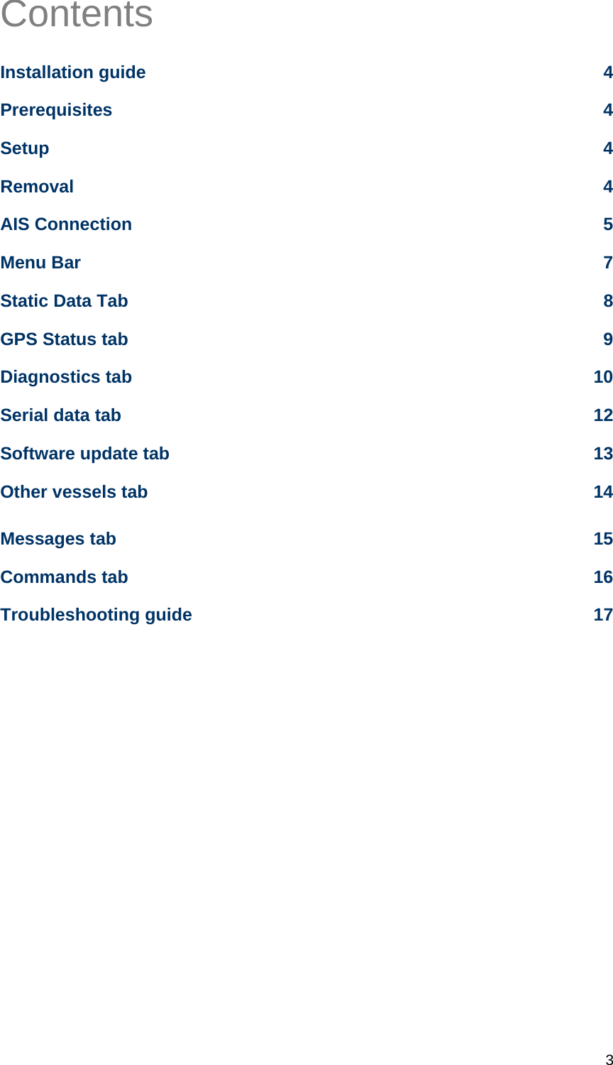
Contents
- 1. Configuration User Guide
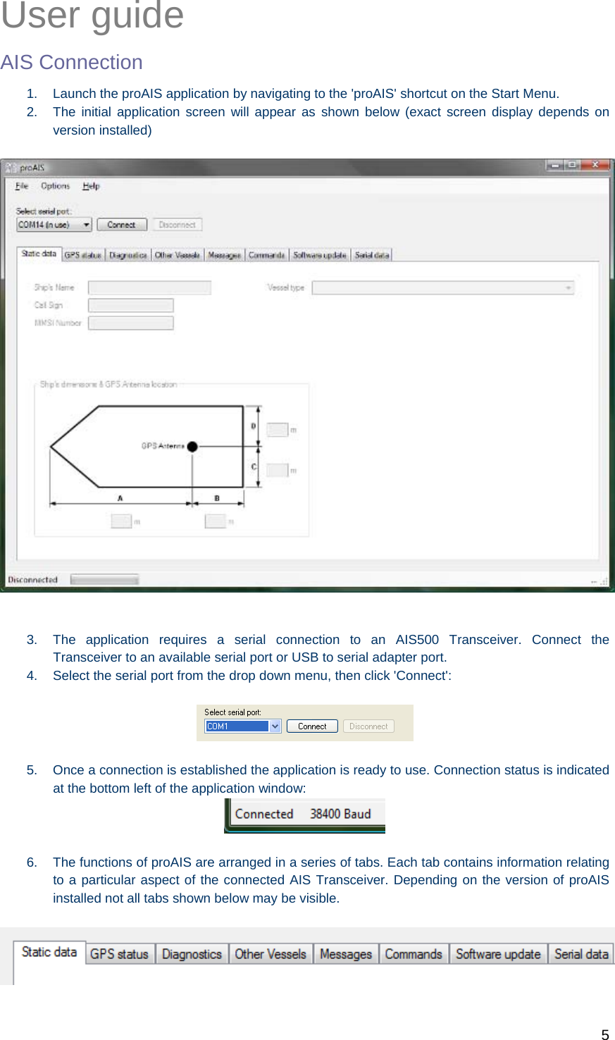
- 2. User Manual
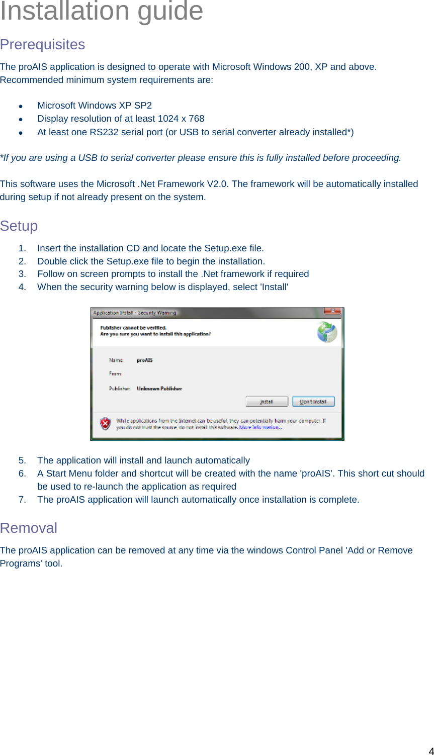
Configuration User Guide

![2 GENERAL WARNINGS All Class A and Class B marine Automatic Identification System (AIS) units utilize a satellite based system such as the Global Positioning Satellite (GPS) network or the Global Navigation Satellite System (GLONASS) network to determine position. The accuracy of these systems is variable and is affected by factors such as the antenna positioning, how many satellites are used to determine a position and how long satellite information has been received for. It is desirable wherever possible therefore to verify both your vessels AIS derived position data and other vessels AIS derived position data with visual or radar based observations. The proAIS application is intended for use as an installation and configuration tool. The application is not a navigation tool and should not be used as such. LICENSING IMPORTANT: In most countries the operation of an AIS unit is included under the vessels marine VHF licence provisions. The vessel on to which the AIS unit is to installed must therefore possess a current VHF radiotelephone license which lists the AIS system and the vessel Call Sign and MMSI number. Please contact the relevant authority in your country for more information. In accordance with a policy of continual development and product improvement the AIS500 hardware and software may be upgraded from time to time and future versions of the AIS500 may therefore not correspond exactly with this manual. When necessary, upgrades to the product will be accompanied by updates or addenda to this manual. Please take time to read this manual carefully and to understand its contents fully so that you can install and operate your AIS system correctly. Information contained in this manual is liable to change without notice. [company] Inc and Software Radio Technology plc disclaim any liability for consequences arising from omissions or inaccuracies in this manual and any other documentation provided with this product. DISCLAIMER THIS SOFTWARE IS PROVIDED BY THE COPYRIGHT HOLDERS AND CONTRIBUTORS "AS IS" AND ANY EXPRESS OR IMPLIED WARRANTIES, INCLUDING, BUT NOT LIMITED TO, THE IMPLIED WARRANTIES OF MERCHANTABILITY AND FITNESS FOR A PARTICULAR PURPOSE ARE DISCLAIMED. IN NO EVENT SHALL THE COPYRIGHT OWNER OR CONTRIBUTORS BE LIABLE FOR ANY DIRECT, INDIRECT, INCIDENTAL, SPECIAL, EXEMPLARY, OR CONSEQUENTIAL DAMAGES (INCLUDING, BUT NOT LIMITED TO, PROCUREMENT OF SUBSTITUTE GOODS OR SERVICES; LOSS OF USE, DATA, OR PROFITS; OR BUSINESS INTERRUPTION) HOWEVER CAUSED AND ON ANY THEORY OF LIABILITY, WHETHER IN CONTRACT, STRICT LIABILITY, OR TORT (INCLUDING NEGLIGENCE OR OTHERWISE) ARISING IN ANY WAY OUT OF THE USE OF THIS SOFTWARE, EVEN IF ADVISED OF THE POSSIBILITY OF SUCH DAMAGE. This software uses components and source code developed by other companies or groups. Microsoft .Net Framework V2.0: Copyright © 2005 Microsoft Corporation ZedGraph Graphing component dll (http://zedgraph.org): Provided under the GNU Lesser General Public License All trademarks mentioned in this document are the property of their respective owners. Copyright © 2008](https://usermanual.wiki/Flir-BelgiumBA/AIS500.Configuration-User-Guide/User-Guide-1106458-Page-2.png)
![8 Static Data Tab This tab shows the current configuration of the AIS Transceiver. When an AIS500 Transceiver is connected for the first time the display will be similar to that shown below: Vessel details The vessel details below will be pre-programmed into you’re AIS500. The required vessel data includes: Vessel name Radio call sign (if available) MMSI number Vessel dimensions including AIS GPS antenna location (in meters, to the nearest meter) Vessel type (from a pre-defined list of vessel types) If any of the pre-programmed information is incorrect please contact [company] to arrange for the data to be corrected before using you’re AIS500. It is not possible to change the programmed information yourself.](https://usermanual.wiki/Flir-BelgiumBA/AIS500.Configuration-User-Guide/User-Guide-1106458-Page-8.png)
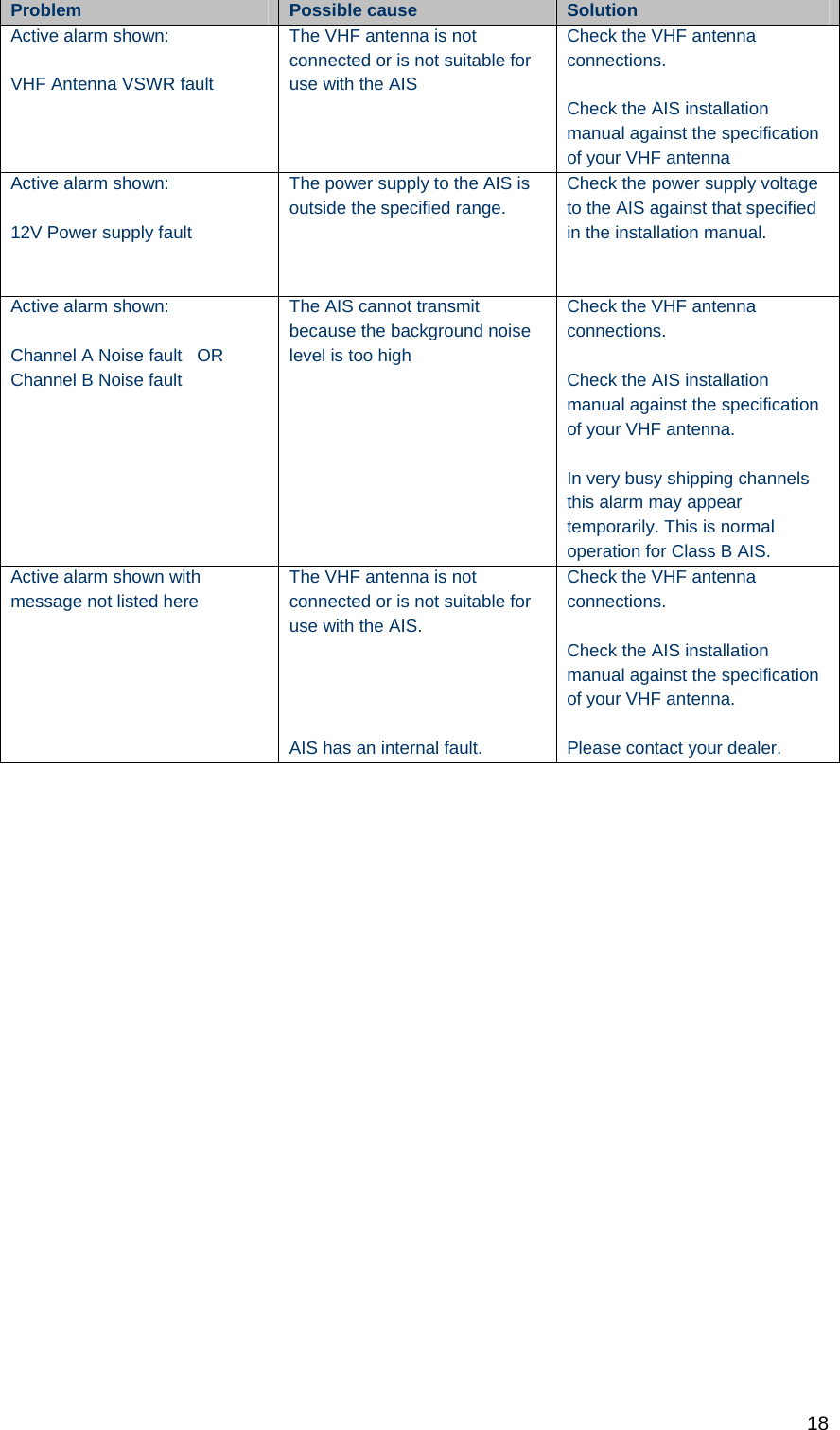
![17 Troubleshooting guide Problem Possible cause Solution General No AIS is detected The AIS is not connected to the serial port selected from the drop down menu The AIS is not powered The serial cable is damaged or faulty Check the number of the serial port the AIS is connected to and retry Check that the power supply is connected and switched on Try an alternative serial cable Can not communicate with unit The AIS is not connected to the serial port selected from the drop down menu The Serial cable is damaged or faulty Check the number of the serial port the AIS is connected to and retry Try an alternative serial cable Static Data tab No static data is displayed The unit has not yet been configured Contact [company] to have the transponder correctly configured The MMSI or vessel data can not be changed The data has already been programmed The data can only be programmed once. If it is incorrect please contact [company]. The static data is incorrect Data was entered incorrectly Contact [company] to have the transponder correctly configured GPS tab No GPS position information is displayed (or graph shows only blue bars) The unit has not acquired GPS fix The GPS antenna is not correctly connected The GPS antenna does not have a clear view of the sky GPS antenna is unsuitable for use with AIS Check the GPS antenna connections and power cycle the AIS unit. Check the GPS antenna location and make sure it's view of the sky is not obstructed Check the AIS installation manual against the specification of your GPS antenna Diagnostics tab Red cross against a status item Unit configuration or antenna connections See Diagnostics tab section of this user guide for advice on each item Active alarm shown: Position sensor fault OR SOG data fault OR COG data fault OR The unit has not acquired GPS fix Wait at least five minutes for the unit to acquire GPS position fix Follow troubleshooting guide for GPS tab](https://usermanual.wiki/Flir-BelgiumBA/AIS500.Configuration-User-Guide/User-Guide-1106458-Page-17.png)