Flir BelgiumBA BASE Base Station - Autopilot radio interface node User Manual 509875
Raymarine UK Ltd. Base Station - Autopilot radio interface node 509875
User Manual

EMBER & RAYMARINE LIMITED - COMPANY CONFIDENTIAL
D619SP06 Issue 1.0 Page 1 DO NOT DISTRIBUTE
Project Development Number
RF Products - Technical Description D619
Prepared by Date Issue
Neal Hewer – Raymarine 11th January 2005 1.0
RAYMARINE LIMITED/RAYMARINE INC PROPRIETARY DATA
This document contains proprietary technical data pertaining to items, or components, or
processes or other matter developed or acquired at the private expense of Raymarine
Limited/Raymarine Inc and is restricted to use only by Raymarine employees or other
persons authorised by Raymarine Limited/Raymarine Inc in writing to use it. Neither said
document nor said technical data shall be furnished or disclosed to or copied or used by
persons outside Raymarine Limited/Raymarine Inc without the express written approval
of Raymarine Limited/Raymarine Inc.
Issued copies to be signed off below:
On Behalf of Raymarine Limited/Raymarine Inc Date
IMPORTANT NOTE
This document is controlled under PVCS. It is the responsibility of the person using this
document to ensure that it is the latest Revision. If there is any doubt about whether or
not this document is the latest Revision then please check with the Vessel Control and
Data Manager.

EMBER & RAYMARINE LIMITED - COMPANY CONFIDENTIAL
D619SP06 Issue 1.0 Page 2 DO NOT DISTRIBUTE
Change Notes
Revision Description Date
0.01 Initial Draft 29 October, 2004
0.02 EMC units added 16 November, 2004
0.03 Minor changes to text. Changes from previous Issue marked with a
right hand sidebar where practicable.
6th January, 2005
1.0 Initial Issue 11th January 2005

EMBER & RAYMARINE LIMITED - COMPANY CONFIDENTIAL
D619SP06 Issue 1.0 Page 3 DO NOT DISTRIBUTE
Abbreviations
Abbreviation Description
RCM Raydio Communications Module
GW Gateway
HC Handheld Controller
SOF Start Of Frame
EOF End Of Frame
RFIC Radio Frequency Integrated Circuit
REAP Raymarine to Ember Application Protocol
UART Universal Asynchronous Receiver Transmitter
SPI Serial Peripheral Interface
EMBER & RAYMARINE LIMITED - COMPANY CONFIDENTIAL
D619SP06 Issue 1.0 Page 4 DO NOT DISTRIBUTE
CONTENT
1 Purpose ...........................................................................................................................5
2 Product Overview ...........................................................................................................5
2.1 BASE ..........................................................................................................................5
2.2 S1000 ........................................................................................................................5
2.3 S100 ..........................................................................................................................5
2.4 SMART CONTROLLER ...................................................................................................6
2.5 PRODUCT MATRIX ........................................................................................................6
3 Hardware Overview.........................................................................................................7
3.1 SYSTEM BLOCK DIAGRAM .............................................................................................7
3.2 IMPLEMENTATION .........................................................................................................7
3.3 APPLICATION ...............................................................................................................8
3.3.1 Rule 1 – Data on Request...................................................................................8
3.3.2 Rule 2 – Frame usage ........................................................................................8
3.3.3 Rule 3 – Periodicity.............................................................................................8
3.4 GATEWAY (GW) ..........................................................................................................9
3.4.1 EM2420 Control..................................................................................................9
3.4.2 EmberNet Networking.........................................................................................9
3.4.3 Pass Through to the Host Processor ..................................................................9
3.5 HANDHELD CONTROLLER (HC) ...................................................................................10
3.5.1 EM2420 Control................................................................................................10
3.5.2 EmberNet Networking.......................................................................................10
3.5.3 Pass Through to the Host Processor ................................................................10
3.5.4 Power Consumption .........................................................................................10
4 Summary .......................................................................................................................12

EMBER & RAYMARINE LIMITED - COMPANY CONFIDENTIAL
D619SP06 Issue 1.0 Page 5 DO NOT DISTRIBUTE
1 Purpose
The purpose of this document is to outline Raymarine’s Embedded Wireless Networking
Technology.
Raymarine are developing four products. They are:
1. BASE
2. S1000 (Autopilot)
3. S100 (Autopilot Controller)
4. SMART CONTROLLER
As such these developments can be grouped by into two distinct, and quite different wireless
categories. These are:
1. GW - Gateway
2. HC - Handheld Controller
The following Sections consider an overview of the products, the RF technology used and the
distinction between Gateway & Handheld Controller.
2 Product Overview
2.1 Base
The Base is a Gateway.
It may be used in conjunction with the S100 or the Smart Controller.
Its function is to act as bridge between a wired communication system (SeaTalk) and
wireless products for the transfer of data and commands. For example, it will be capable of
transferring control information to a wired Autopilot and vessel information such as Boat
Speed, Wind Direction, etc,.
2.2 S1000
The S1000 is a Gateway.
It will be used in conjunction with the S100.
Its function is a Wirelessly Controlled Autopilot. It uses a combination of GPS and vessel
attitude to maintain the vessel on a pre-determined course.
2.3 S100
The S100 is a Handheld Controller.
It may be used in conjunction with the S1000 or the Base.
Its function is control both the S1000 and existing wired Autopilots available via the Base.
There is only one Autopilot per system. The S100 issues commands to the Autopilot that

EMBER & RAYMARINE LIMITED - COMPANY CONFIDENTIAL
D619SP06 Issue 1.0 Page 6 DO NOT DISTRIBUTE
change its mode of operation. For example, from Standby to Auto and vice versa, course
changes, etc… It also displays the current Autopilot status.
2.4 Smart Controller
The Smart Controller is a Handheld Controller.
It will be used in conjunction with the Base
Its function is to control a wired Autopilot as well as displaying vessel data that is available on
the wired system to which the Base is attached. It issues commands to the Autopilot that
change the mode of the Autopilot. For example, from Standby to Auto and vice versa, course
changes, etc… It also displays the current Autopilot status. It also gathers vessel data such
as Alarms, Boat Speed, and Water Depth etc,.
2.5 Product Matrix
These four products will be combined with ancillary equipment in three packages. This
defines the three applications for Notified Body Opinion under the R&TTE Directive.
Product Matrix
System Smart
Controller
S100 S1000 Base Pump Fitting Kit
E15023 X X
E12169 X X X X
E15024 X X
EMBER & RAYMARINE LIMITED - COMPANY CONFIDENTIAL
D619SP06 Issue 1.0 Page 7 DO NOT DISTRIBUTE
3 Hardware Overview
This Section provides a general overview of the hardware implementation for both the
Gateway and the Handheld Controller.
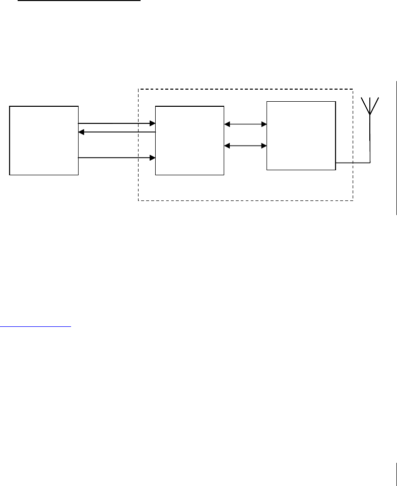
3.1 System Block Diagram
The illustration below is a block diagram for the solution.
The Raydio Communication Module (RCM) is based upon Ember’s EM2420 2.45GHz RF
transceiver connected to an ATMEGA64 microprocessor, the Network Processor. This
Network Processor runs EmberStack - Ember’s networking embedded wireless networking
solution.
3.2 Implementation
This solution is based upon IEEE 802.15.4. It uses Ember’s EM2420 integrated solution
(www.ember.com) and Embernet, Ember’s networking software.
Key Features
• 2400 – 2483.5 MHz Range
o 16 channels from 2405MHz to 2480MHz @ 5MHz intervals
o Fixed channel operation – No channel hopping
• Direct Sequence Spread Spectrum
• 0dBm (nom) output power
• –90dBm (nom) receiver sensitivity
• Point-to-point and mesh networking capability
Host Processor Network
Processor
RX
TX
#RESET
Ra
y
dio Communication Module
Host Processor Network
Processor
RX
TX
#RESET
Ra
y
dio Communication Module
Host Processor Network
Processor
RF Transceiver
EM2420
RX
TX
#RESET
Ra
y
dio Communication Module
SPI
CONTROL

EMBER & RAYMARINE LIMITED - COMPANY CONFIDENTIAL
D619SP06 Issue 1.0 Page 8 DO NOT DISTRIBUTE
3.3 Application
The application of this solution follows the rules below.
3.3.1 Rule 1 – Data on Request
This RF system is not a broadcast system. Data must be requested using the PID request
mechanism for the following reasons:
1. Reduced power consumption
2. Reduced on-air time
3. To avoid synchronisation problems
Typically a Handheld Controller will request data and stay awake until it has received the
requested data (these being battery powered nodes).
The Gateway services the Handheld Controller requests. Since it is a powered node it can
stay awake, permanently listening for requests and incoming data.
3.3.2 Rule 2 – Frame usage
Data is sent in 91-byte data frames. For optimum performance the frame is used to transport
multiple data entries.
3.3.3 Rule 3 – Periodicity
Data will be requested no more than once a second. The exception to this rule is when an
immediate response is required that would otherwise have an immediate impact on the
functionality of the product / system. For example, changing Autopilot mode would be
considered as being acceptable.

EMBER & RAYMARINE LIMITED - COMPANY CONFIDENTIAL
D619SP06 Issue 1.0 Page 9 DO NOT DISTRIBUTE
3.4 Gateway (GW)
The GW is an always-powered device, which will serve requests initiated by Handheld
Controllers. This design uses PCB mounted antenna. Its role is to interact with the
SeaTalk bus caching data locally, in order to speed up remote transactions. Since the GW
is always powered it will be used as a relay / routing device. The embedded software running
on the network processor of the GW performs the following functions:
1. Control the EM2420 RFIC
2. Perform networking functions required by EmberNet
3. Act as protocol gateway, passing data through to the host using the REAP protocol
via a UART.
4. Provide a means of indicating registration activity
5. Manage and maintain all ‘binding’ information
6. The primary role of the Host Processor is to provide product functionality and not RF
networking capability
Details for each of these functions are as follows.
3.4.1 EM2420 Control
The software is responsible for all interactions between the network processor and the
EM2420 RFIC. The software performs power-on configuration of the EM2420, upper-level
MAC functions, SPI communications, and other necessary services.
3.4.2 EmberNet Networking
The software implements the EmberNet stack. It performs all basic messaging services
including origination, acknowledgement, and forwarding. It supports acknowledged
transmissions, route discovery / maintenance, device discovery, and network diagnostics.
3.4.3 Pass Through to the Host Processor
For communication between the network processor and the host microcontroller a simple
protocol, known as Raymarine to Ember Application Protocol (REAP) will be established. In
general this protocol simply takes advantage of the existing Raymarine protocol definition.

EMBER & RAYMARINE LIMITED - COMPANY CONFIDENTIAL
D619SP06 Issue 1.0 Page 10 DO NOT DISTRIBUTE
3.5 Handheld Controller (HC)
The HC is a highly power conscious device which will be asleep most of the time in order to
preserve power. This design uses an inverted ‘F’ tracked antenna. It will initiate
communication on the network and stay awake long enough to hear responses. It will
primarily perform ‘set and get’ operations on the gateway to which it is bound. The embedded
software running on the networking microprocessor of HC performs the following functions:
1. Control the EM2420 RFIC
2. Perform networking functions required by EmberNet
3. Act as protocol gateway, passing data through to the host using the REAP protocol
via a UART.
4. Minimize power consumption
5. Get and Set operations performed on a 1 second interval
6. Operations that would affect the functionality of the product
7. The primary role of the Host Processor is to provide product functionality and not RF
networking capability
Details for each of these functions are as follows.
3.5.1 EM2420 Control
The software is responsible for all interactions between the network processor and the
EM2420 RFIC. The software performs power-on configuration of the EM2420, upper-level
MAC functions, SPI communications, and other necessary services.
3.5.2 EmberNet Networking
The software implements the EmberNet stack. It performs all basic messaging services
including origination, and acknowledgement. It supports “best effort” and connection-based
messaging, route discovery / maintenance, device discovery, and network diagnostics. In
order to minimize power consumption, routing and repeating functionality will be disabled on
the HC device.
3.5.3 Pass Through to the Host Processor
For communication between the network processor and the host processor a simple protocol,
known as Raymarine to Ember Application Protocol (REAP) will be established. In general
this protocol simply takes advantage of the existing Raymarine protocol definition.
3.5.4 Power Consumption
In order to achieve the aggressive battery life, expected from the HC, the network processor
must be extremely power conscious. This will mean turning off any unused peripherals on the
network processor, as well as structuring the code in such a manner that it sleeps as often as
possible, and changing the time base prescaler to maximize asleep time.
In effect, the network processor software should be kept as autonomous as possible from the
host. The host will only be able to wake the network processor by an external interrupt. The
goal will then be to execute the command issued by the host in as short a time as possible, in
order to sleep again.
EMBER & RAYMARINE LIMITED - COMPANY CONFIDENTIAL
D619SP06 Issue 1.0 Page 11 DO NOT DISTRIBUTE
In order to further minimize power consumption, the network processor will be called upon,
using specially formed commands to execute repetitive tasks, for the host. This will allow the
host to stay asleep, while the network processor wakes and performs the tasks, the host will
be notified of task results as well as if an error occurs.

EMBER & RAYMARINE LIMITED - COMPANY CONFIDENTIAL
D619SP06 Issue 1.0 Page 12 DO NOT DISTRIBUTE
4 Summary
Outline Summary of Raymarine’s Wireless Products
Product Name Smart Controller S100 S1000 Base
Alias SMART
CONTROLLER
FOB ELP BASE-STATION
Part # A18105 A18104 A18107 A18106
RF Category HC HC GW GW
Schematic
Reference
4593-002 Issue P 4593-004 Issue r 4590-002 Issue L 4619-003 Issue u
PCB Reference 3015-358 Issue E 3015-359 Issue D 3015-344 Issue E 3015-364 Issue D
Output Power Nominally 1mW
(0dBm)
Nominally 1mW
(0dBm)
Nominally 1mW
(0dBm)
Nominally 1mW
(0dBm)
Frequency ANY CHANNEL
16 CHANNELS
FROM 2405MHz TO
2480MHz @ 5MHz
INTERVALS
ANY CHANNEL
16 CHANNELS
FROM 2405MHz TO
2480MHz @ 5MHz
INTERVALS
ANY CHANNEL
16 CHANNELS
FROM 2405MHz TO
2480MHz @ 5MHz
INTERVALS
ANY CHANNEL
16 CHANNELS
FROM 2405MHz TO
2480MHz @ 5MHz
INTERVALS
Bandwidth 2MHz 2MHz 2MHz 2MHz
RF Protocol IEEE 802.15.4
CSMA-CA
IEEE 802.15.4
CSMA-CA
IEEE 802.15.4
CSMA-CA
IEEE 802.15.4
CSMA-CA
Modulation DSSS
FIXED CHANNEL
NO CHANNEL
HOPPING
DSSS
FIXED CHANNEL
NO CHANNEL
HOPPING
DSSS
FIXED CHANNEL
NO CHANNEL
HOPPING
DSSS
FIXED CHANNEL
NO CHANNEL
HOPPING
Duty Cycle 4% 4% 4% 4%
Antenna PCB INVERTED ‘F’ PCB INVERTED ‘F’ PCB MOUNTED
ANTENNA 1/4λ
PCB MOUNTED
ANTENNA 1/4λ
Power Source INTERNAL
RECHARGEABLE
BATTERY
EXTERNAL
POWER SOURCE
(SHIPS BATTERY)
INTERNAL
DISPOSABLE
BATTERY
EXTERNAL
POWER SOURCE
(SHIPS BATTERY)
EXTERNAL
POWER SOURCE
(SHIPS BATTERY)
Default Channel 4 4 4 4