Flir BelgiumBA LTB Wireless MOB System User Manual 87064 1
Raymarine UK Ltd. Wireless MOB System 87064 1
UserManual.wiki
>
Flir BelgiumBA
>
LTB User Manual
>
Installation
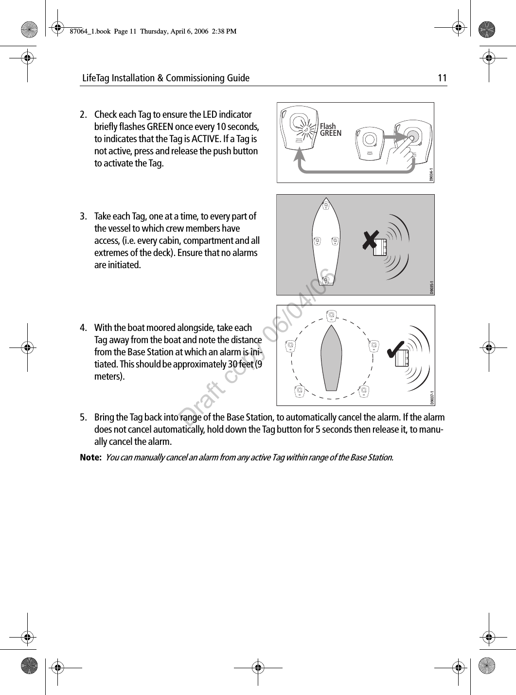
Contents
1.
Installation
2.
System operating guide
3.
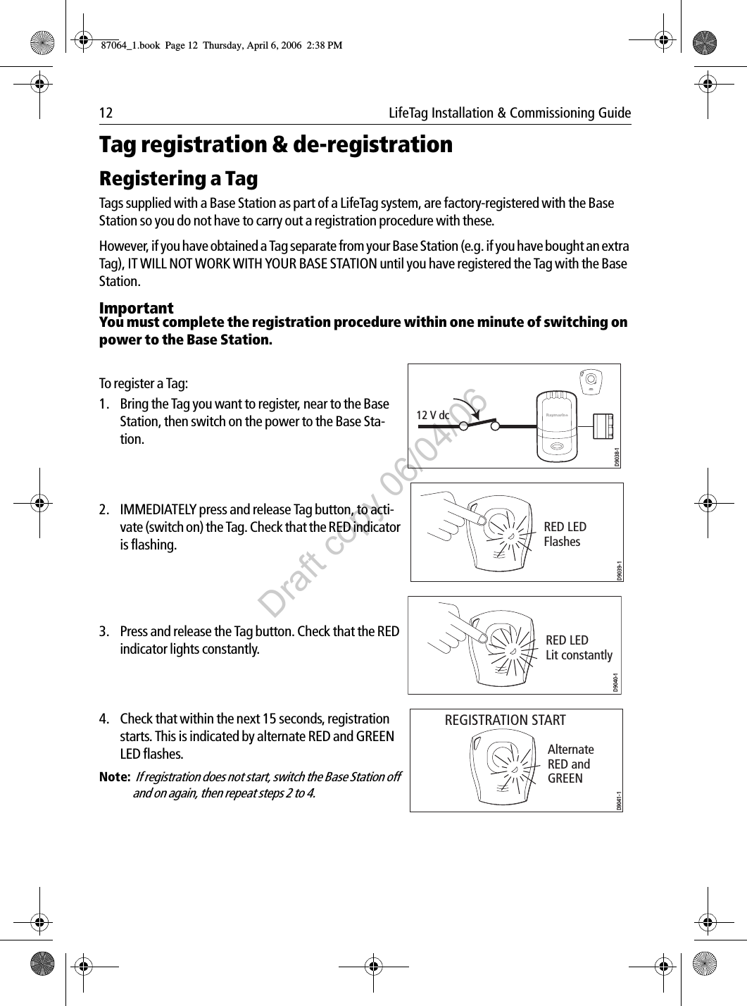
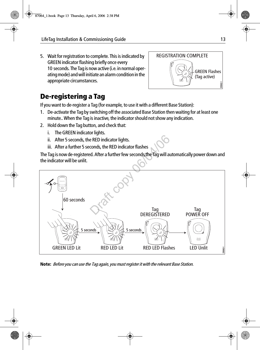
Tag register
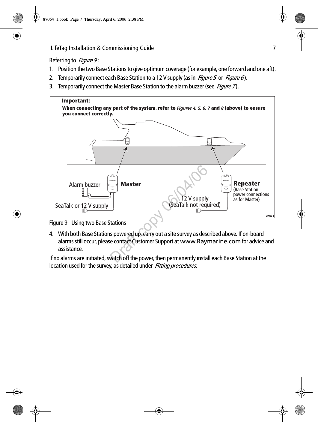
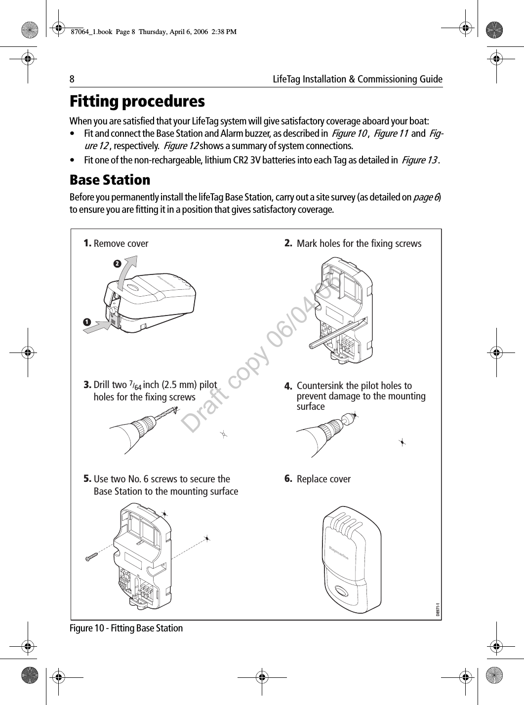
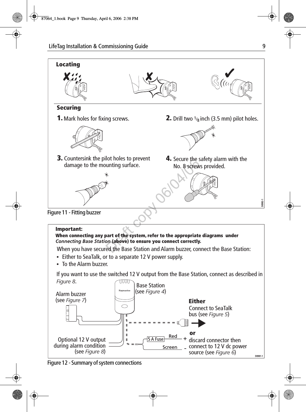
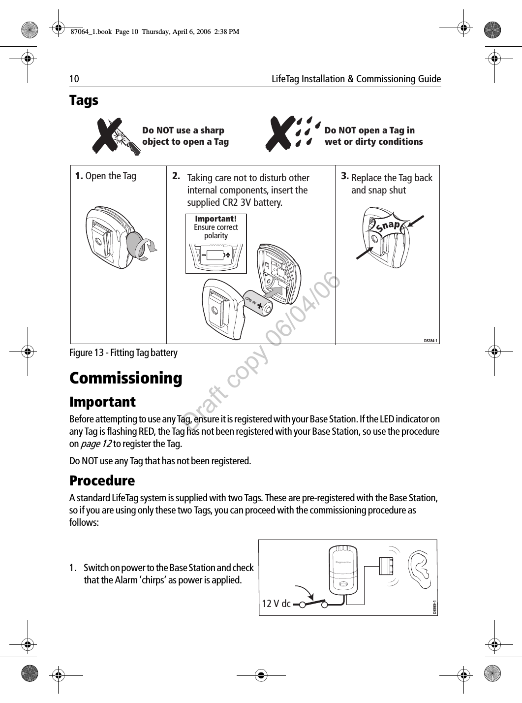
Installation
Navigation menu
Upload a User Manual
Namespaces
Wiki Guide
HTML
PDF
Info
Views
User Manual
Discussion / Help
Navigation