Flir BelgiumBA LTT Wireless MOB System (tag) User Manual 87064 1
Raymarine UK Ltd. Wireless MOB System (tag) 87064 1
Contents
- 1. Install manual
- 2. Operation
- 3. Registration
Install manual
LifeTag System
Installation &
Commissioning Guide
Document reference: 87064-1
Date: April 2006
87064_1.book Page 1 Thursday, April 6, 2006 2:38 PM
Draft copy 06/04/06
Raymarine and SeaTalk are trademarks of Raymarine plc
© Handbook contents copyright Raymarine plc
Important Information
WARNING:LifeTag System
The Raymarine LifeTag system is only an aid to crew safety, and must not be relied
upon as the vessel's main crew safety system. It is the responsibility of the Captain
and all crew members to ensure that all safety instructions and procedures are in
place and obeyed in accordance with local requirements. Failure to operate this
system in accordance with the operating instructions may result in unreliable or
reduced system performance.
WARNING:Lithium Batteries
The LifeTag System Tags use non-rechargeable lithium batteries. Do not attempt
to recharge these batteries. Do not incinerate these batteries. Ensure that these
batteries are replaced with a battery of the same type and check local regulations
when disposing of spent batteries. Incorrectly fitting batteries or using the wrong
battery types may result in un-reliable or reduced system performance.
General Care & Safety
The operation of some medical electronic devices, such as hearing aids and pacemakers, may be
affected if a LifeTag or LifeTag Base Station is used next to them. Observe the makers
recommendations for such devices.
RF Energy
The LifeTag and Lifetag Base Station are low-power radio transceivers. When on, they
intermittently transmit RF energy (radio waves). The LifeTag and LifeTag Base Station are designed
to comply with the limits for RF energy exposure for the general population set by national
authorities and international health agencies, for example BS EN 50371:2002.
Intended Use
The LifeTag and LifeTag Base Station are intended as an aid to safety on leisure vessels and
small workboats.
Waste Electrical and Electronic (WEEE) Directive
The WEEE Directive requires the recycling of waste electrical and electronic equipment.
Whilst the WEEE Directive does not apply to some of Raymarine's products, we support its policy
and ask you to be aware of how to dispose of this product.
The crossed out wheelie bin symbol, illustrated above, and found on our products signifies that this
product should not be disposed of in general waste or landfill.
Please contact your local dealer, national distributor or Raymarine Technical Services for
information on product disposal.
87064_1.book Page 2 Thursday, April 6, 2006 2:38 PM
Draft copy 06/04/06
1
LifeTag Installation & Commissioning Guide
Getting Started
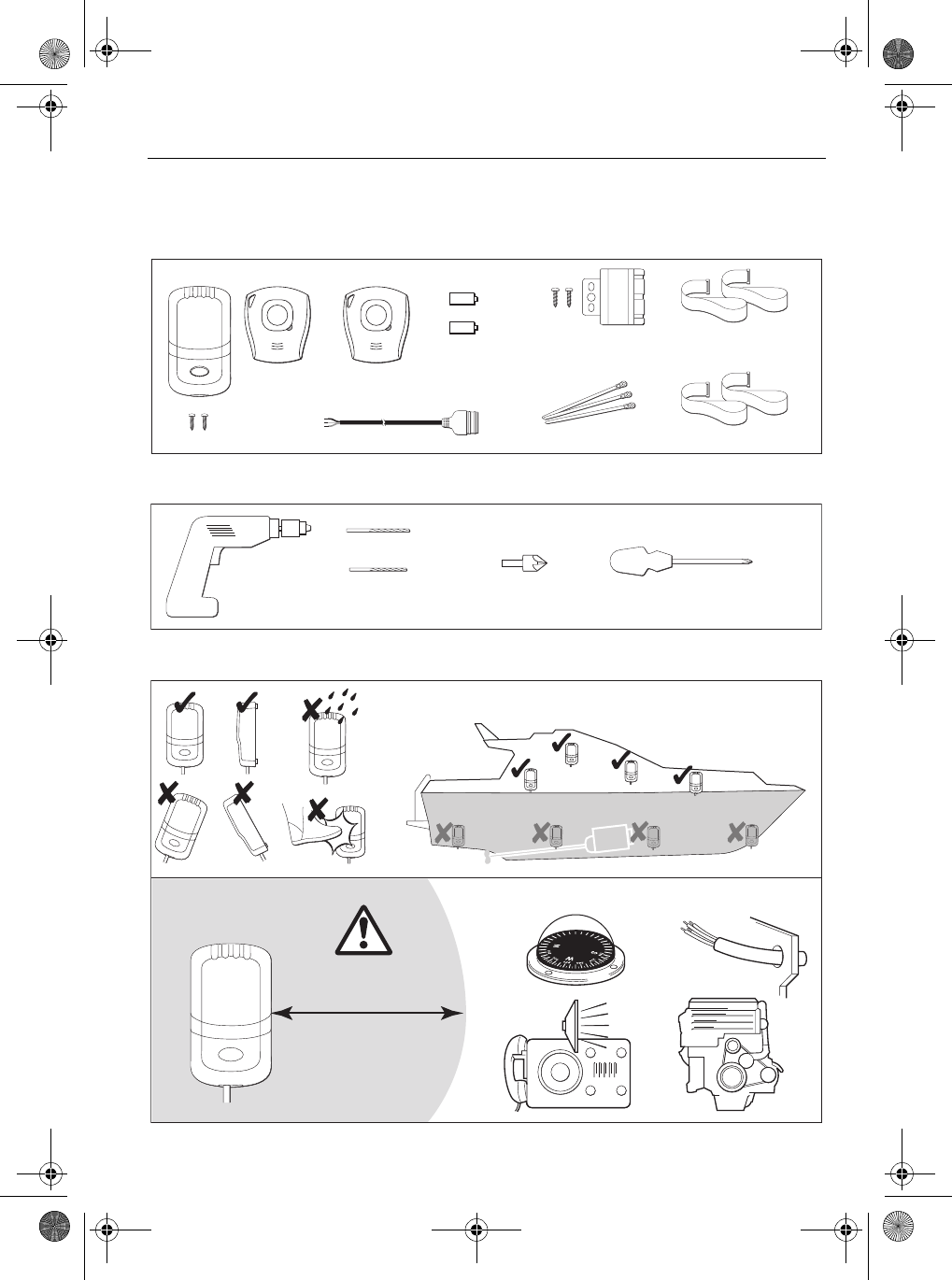
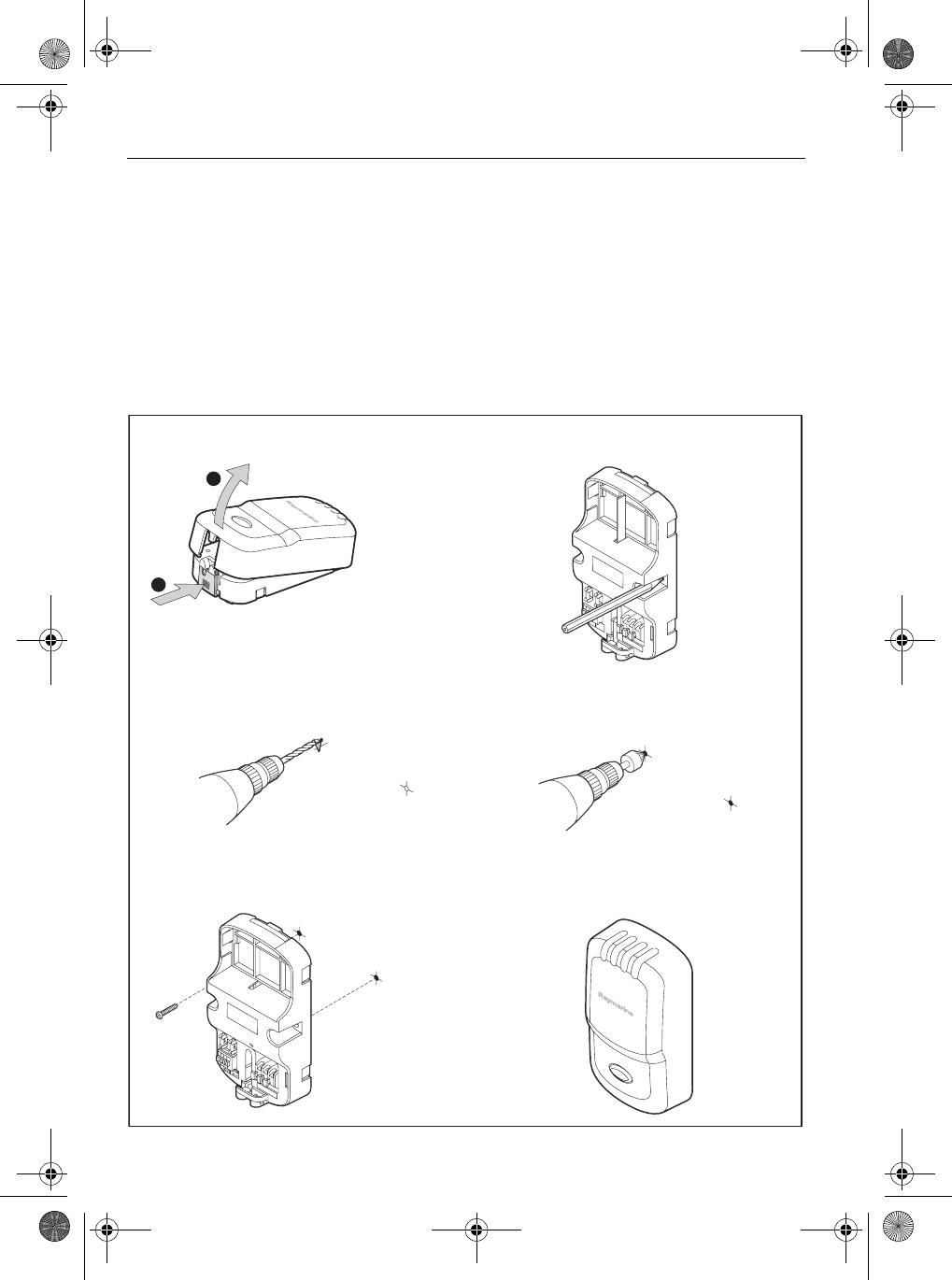
Figure 1 - Parts supplied
Figure 2 - Tools required
Figure 3 - Locating Base Station
Self-tapping
screws x2
Base Station
Straps x2
Strap extensions x2
Tags x2
Cable ties
Buzzer, bracket and
fixing screws x2
CR2 3V lithium
batteries x2
SeaTalk cable
3ft (1 meter)
D8919-1
Pozidriv screwdriver
Power Drill 7/64 inch (2.5 mm) drill
1/8 inch (3.5 mm) drill
Countersink bit
D9029-1
Min 3 ft 3 in (1m)
D8955-1
Fit Base Station as high up as possible, in a dry location
87064_1.book Page 1 Thursday, April 6, 2006 2:38 PM
Draft copy 06/04/06
2 LifeTag Installation & Commissioning Guide
EMC Installation Guidelines
All Raymarine equipment and accessories are designed to the best industry standards for use in the
recreational marine environment.
Their design and manufacture conforms to the appropriate Electromagnetic Compatibility (EMC)
standards, but correct installation is required to ensure that performance is not compromised.
Although every effort has been taken to ensure that they will perform under all conditions, it is
important to understand what factors could affect the operation of the product.
The guidelines given here describe the conditions for optimum EMC performance, but it is recognized
that it may not be possible to meet all of these conditions in all situations. To ensure the best possible
conditions for EMC performance within the constraints imposed by any location, always ensure the
maximum separation possible between different items of electrical equipment.
For optimum EMC performance, it is recommended that wherever possible:
• Raymarine equipment and cables connected to it are:
• At least 3 ft (1 m) from any equipment transmitting or cables carrying radio signals e.g. VHF radios,
cables and antennas. In the case of SSB radios, the distance should be increased to 7 ft (2 m).
• More than 7 ft (2 m) from the path of a radar beam. A radar beam can normally be assumed
to spread 20 degrees above and below the radiating element.
• The equipment is supplied from a separate battery from that used for engine start. Voltage drops
below 10 V in the power supply to our products, and starter motor transients, can cause the equip-
ment to reset. This will not damage the equipment, but may cause the loss of some information
and may change the operating mode.
• Raymarine specified cables are used. Cutting and rejoining these cables can compromise EMC
performance and must be avoided unless doing so is detailed in the installation manual.
• If a suppression ferrite is attached to a cable, this ferrite should not be removed. If the ferrite needs
to be removed during installation it must be reassembled in the same position.
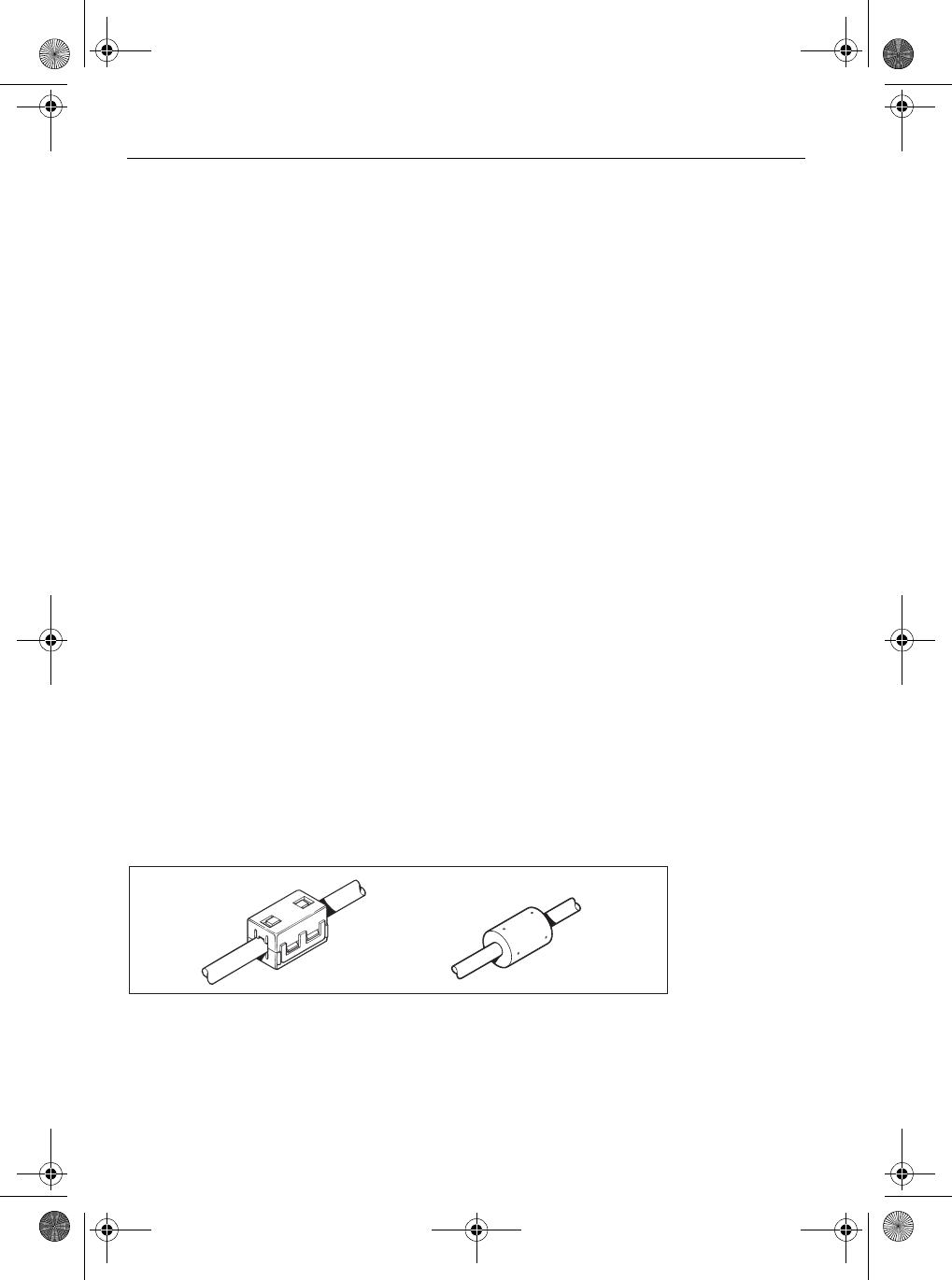
Suppression Ferrites
The following illustration shows typical cable suppression ferrites used with Raymarine equipment.
Always use the ferrites supplied by Raymarine.
Connections to Other Equipment
If your Raymarine equipment is to be connected to other equipment using a cable not supplied by
Raymarine, a suppression ferrite MUST always be attached to the cable near the Raymarine unit.
EMC Conformance
Always check the installation before going to sea to make sure that it is not affected by radio
transmissions, engine starting etc.
D3548-6
87064_1.book Page 2 Thursday, April 6, 2006 2:38 PM
Draft copy 06/04/06
LifeTag Installation & Commissioning Guide 3
Connecting Base Station
The LifeTag system Base Station has to be connected to a 12 V dc power source and to the Alarm
Buzzer:
• Temporary connections are required to enable an initial site survey to be carried out.
• Permanent connections are required when the system is fully installed.
An ancillary switched output is also available from the Base Station. This provides a 12 V output when
an alarm occurs.
After you have made any connections to the Base Station, gently pull the wires, to
ensure that the connections are secure.
Connect SeaTalk cable
The SeaTalk cable provides power in and alarm signal out connections for the Base Station. If SeaTalk
is available use this to connect the Base Station to SeaTalk, as shown in
Figure 5
. If SeaTalk is not
available, use the SeaTalk cable to connect the Base Station to a 12 V dc power source.
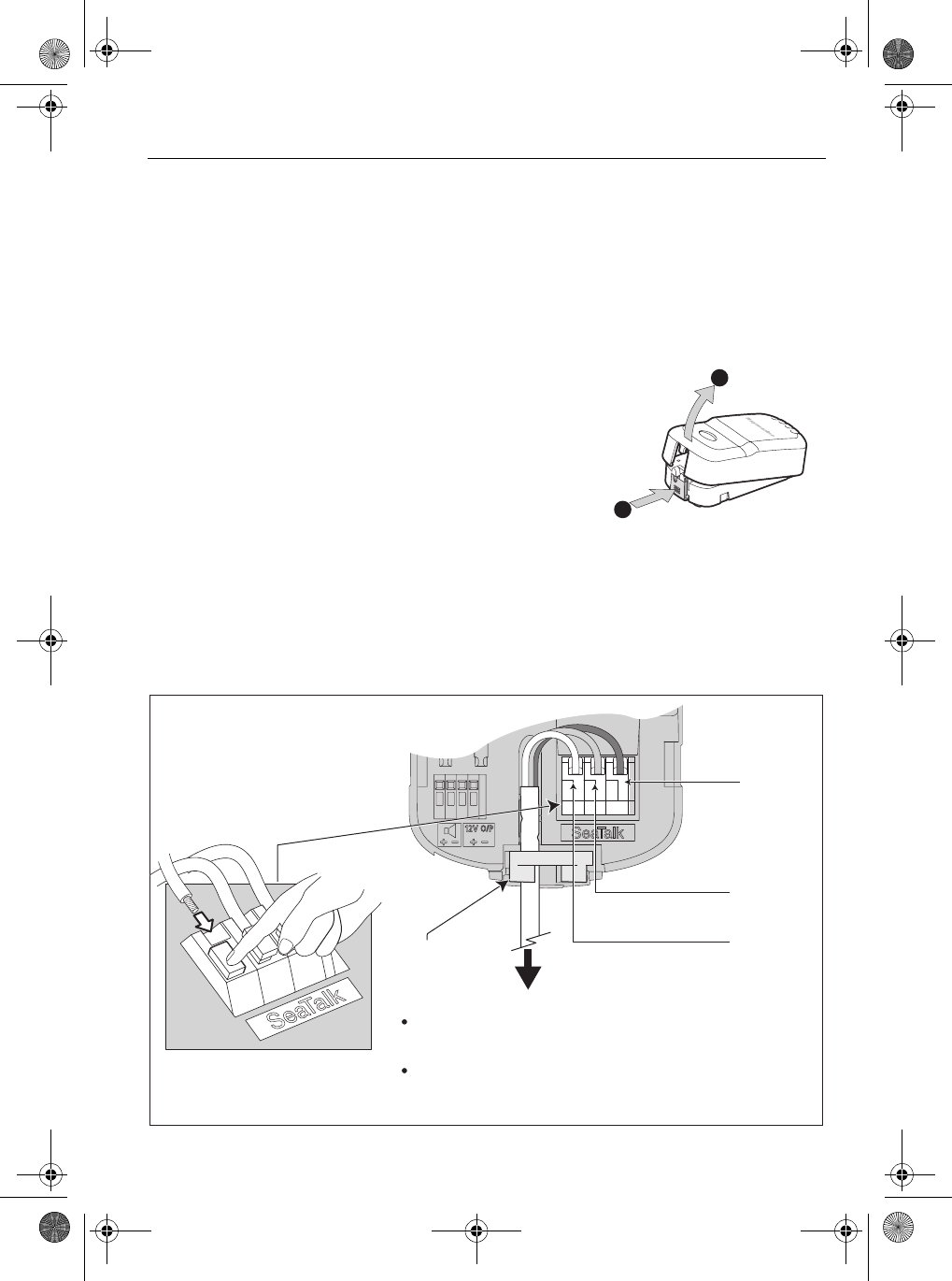
Figure 4 - SeaTalk cable connections to Base Station
The connection procedures are described here once for you to refer
to as necessary, whether you are making temporary connections for
the site survey or making the permanent connections for normal
operation.
To connect your Base Station, ensure the power supply for the Base
Station is switched off, then remove the Base Station cover.
Important
1
2
Raymarine SeaTalk system, if available
or to
Connect SeaTalk cable either to:
See Figures 5 & 6 for connection details
12V dc supply, if SeaTalk system is not, available
Red
(+12 V)
Screen
(Gray, -ve)
Yellow
(Data)
Cable
restraint
D8970-1
87064_1.book Page 3 Thursday, April 6, 2006 2:38 PM
Draft copy 06/04/06
4 LifeTag Installation & Commissioning Guide
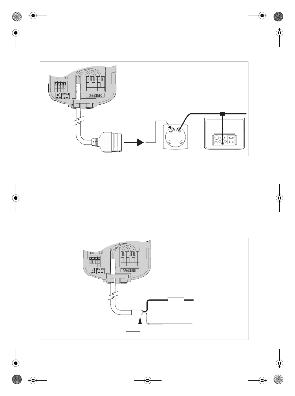
Connecting Base Station to SeaTalk
Figure 5 - Base Station connection to SeaTalk
Compatibility with other Seatalk Products
If the LifeTag Base Station is connected to a Seatalk system which includes a SeaTalk chartplotter and
GPS, and a LifeTag alarm occurs, a MOB marker will be displayed on the chartplotter at the location of
the MOB event. In addition, the chartplotter and compatible Seatalk instruments (such as ST60+
Graphic and ST290 Graphic instruments) will display a MOB 999 Waypoint Name, and range / bearing
or latitude/longitude to the MOB location, plus elapsed time since the MOB event.
This occurs only with compatible products on SeaTalk systems. It does NOT occur on other products
connected via NMEA0183.
SeaTalk not available
Figure 6 - SeaTalk power connections when SeaTalk is not available
SeaTalk bus
D8976-1
Ensure that the 12 V supply on the
SeaTalk bus is protected by a 5 A fuse.
Important:
Cut back and insulate YELLOW wire
Remove & discard connector.
Red
Screen
5 A Fuse +12 V
0 V (typically
battery -ve)
D8976-1
87064_1.book Page 4 Thursday, April 6, 2006 2:38 PM
Draft copy 06/04/06
LifeTag Installation & Commissioning Guide 5
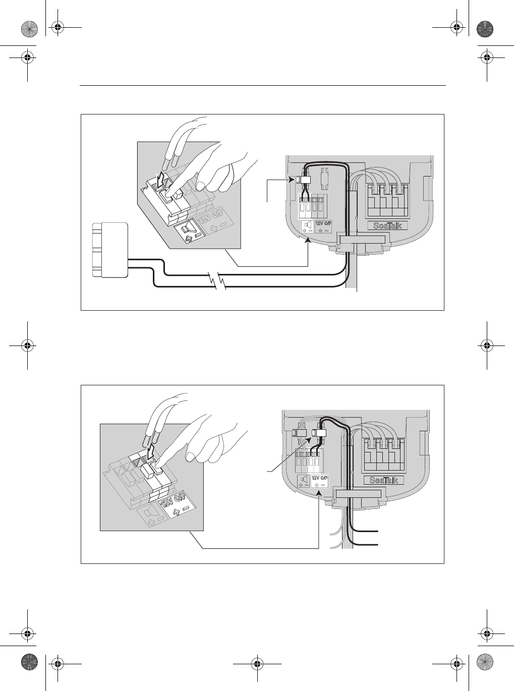
Connect Alarm buzzer
Figure 7 - Alarm buzzer connections
Connect switched 12 V output (optional)
The switched 12 V output can be used to automatically trigger appropriate emergency systems, when
a MOB event occurs.
Figure 8 - Optional 12 V output connection
Base Station
Alarm buzzer Fit cable tie
D9007-1
D9032-1
Base Station
}12 V output
during alarm
condition
Fit cable tie
87064_1.book Page 5 Thursday, April 6, 2006 2:38 PM
Draft copy 06/04/06

6 LifeTag Installation & Commissioning Guide
Ensure satisfactory LifeTag coverage
The nominal LifeTag Base Station-to-Tag range is 30 feet (9 meters), so on boats where this
separation is unlikely to be exceeded, the LifeTag system should operate satisfactorily with just one
Base Station, provided it is positioned for optimum performance, as detailed in
Figure 3
.
However, system performance can be affected by obstructions (superstructure, decking, bulkheads
etc) so to ensure satisfactory operation, it is strongly recommended you carry out a site survey to
ensure satisfactory system operation, before permanently installing the LifeTag Base Station.
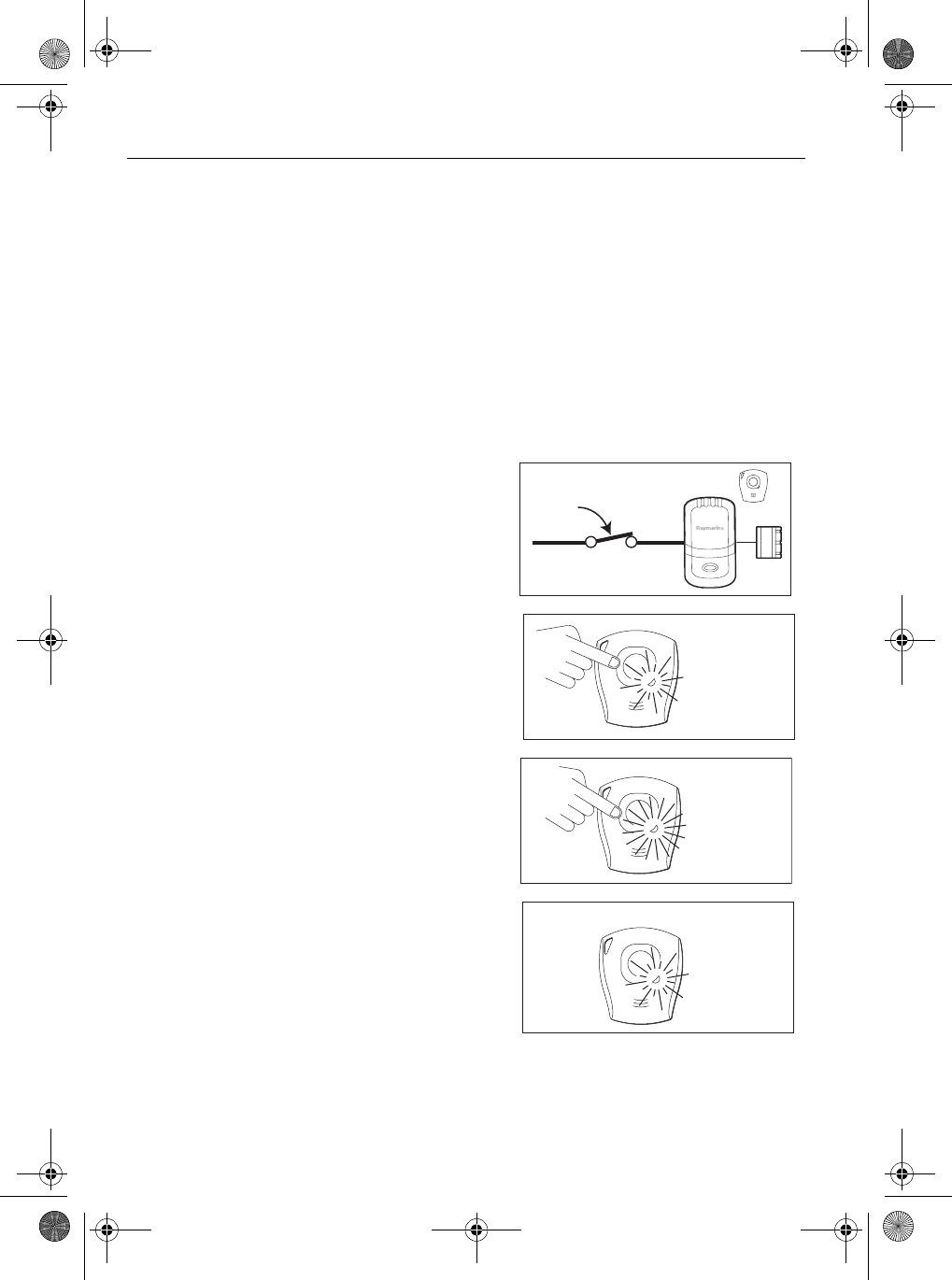
Site survey
To carry out a site survey:
1. Referring to
Figure 3
, place the Base Station at the location you intend installing it and tempo-
rarily connect it either to Seatalk as described in
Figure 5
or to a separate 12 V dc supply via a 5 A
fuse, as described in
Figure 6
.
2. Temporarily connect the alarm buzzer to the Base Station, as described in
Figure 7
.
3. Switch on the 12 V supply to the Base Station.
4. Take one of the Tags supplied with the Base Station and ensure that the LED briefly flashes GREEN
once every 10 seconds to indicate the Tag is active. If the Tag is not active, press and release the
Tag push button to activate the Tag.
5. Take the Tag to every part of the vessel to which crew members have access, (i.e. every cabin, com-
partment and all extremes of the deck), to check if an alarm is initiated.
6. Take the appropriate action as detailed for either
No alarm
or
Alarm initiated
, below.
No alarm
If no alarms are initiated during the site survey, the LifeTag system is operating satisfactorily with the
Base Station at its current location. Switch off the power, then permanently install the Base Station at
that location, as detailed under
Fitting procedures
, below.
Alarm initiated
If an alarm is initiated at any time during the site survey
1. Bring the Tag back into range of the Base Station, to automatically cancel the alarm. If the alarm
does not cancel automatically, hold down the Tag button for 5 seconds then release it, to manu-
ally cancel the alarm..
2. Reposition the Base Station, then carry out another site survey.
If on-board alarms still occur, you need to install a second Base Station, so that the system comprises
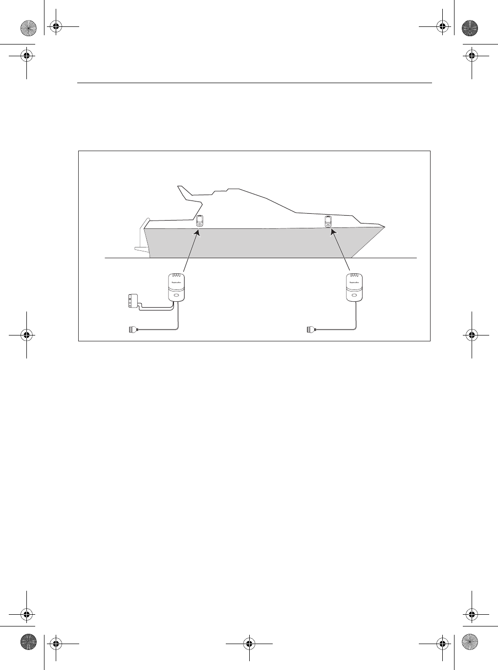
a Master Base Station (the original Base Station), and a Repeater Base Station (the second one).
87064_1.book Page 6 Thursday, April 6, 2006 2:38 PM
Draft copy 06/04/06
LifeTag Installation & Commissioning Guide 7
Referring to
Figure 9
:
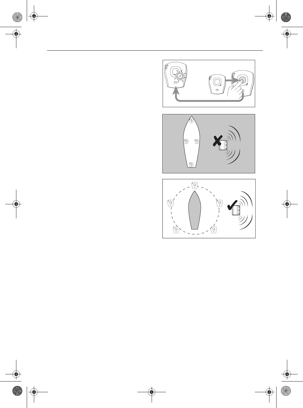
1. Position the two Base Stations to give optimum coverage (for example, one forward and one aft).
2. Temporarily connect each Base Station to a 12 V supply (as in
Figure 5
or
Figure 6
).
3. Temporarily connect the Master Base Station to the alarm buzzer (see
Figure 7
).
Figure 9 - Using two Base Stations
4. With both Base Stations powered up, carry out a site survey as described above. If on-board
alarms still occur, please contact Customer Support at www.Raymarine.com for advice and
assistance.
If no alarms are initiated, switch off the power, then permanently install each Base Station at the
location used for the survey, as detailed under
Fitting procedures
.
Alarm buzzer
Important:
When connecting any part of the system, refer to Figures 4, 5, 6, 7 and 8 (above) to ensure
you connect correctly.
SeaTalk or 12 V supply
12 V supply
(SeaTalk not required)
Master Repeater
(Base Station
power connections
as for Master)
D9033-1
87064_1.book Page 7 Thursday, April 6, 2006 2:38 PM
Draft copy 06/04/06
8 LifeTag Installation & Commissioning Guide
Fitting procedures
When you are satisfied that your LifeTag system will give satisfactory coverage aboard your boat:
• Fit and connect the Base Station and Alarm buzzer, as described in
Figure 10
,
Figure 11
and
Fig-
ure 12
, respectively.
Figure 12
shows a summary of system connections.
• Fit one of the non-rechargeable, lithium CR2 3V batteries into each Tag as detailed in
Figure 13
.
Base Station
Before you permanently install the lifeTag Base Station, carry out a site survey (as detailed on
page 6
)
to ensure you are fitting it in a position that gives satisfactory coverage.
Figure 10 - Fitting Base Station
2.1. Mark holes for the fixing screws
Remove cover
6. Replace cover
5.
D8971-1
1
2
4. Countersink the pilot holes to
prevent damage to the mounting
surface
Use two No. 6 screws to secure the
Base Station to the mounting surface
3. Drill two
7/64 inch (2.5 mm) pilot
holes for the fixing screws
87064_1.book Page 8 Thursday, April 6, 2006 2:38 PM
Draft copy 06/04/06
LifeTag Installation & Commissioning Guide 9
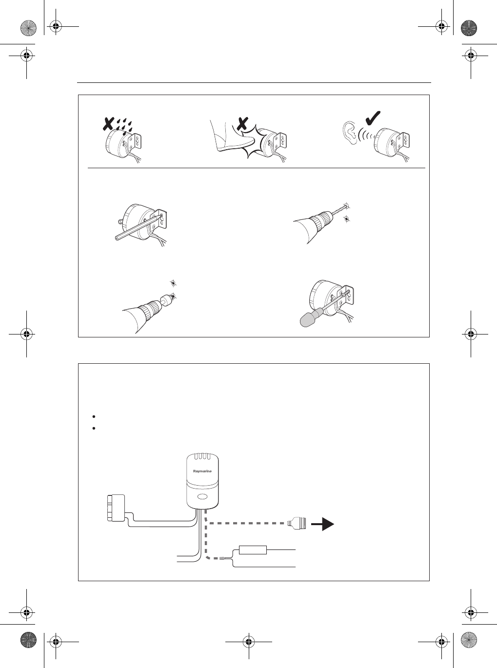
Figure 11 - Fitting buzzer
Figure 12 - Summary of system connections
D8982-1
1. 2.
4.
3.
Mark holes for fixing screws. Drill two 1/8 inch (3.5 mm) pilot holes.
Secure the safety alarm with the
No. 8 screws provided.
Countersink the pilot holes to prevent
damage to the mounting surface.
Locating
Securing
D8981-1
When you have secured the Base Station and Alarm buzzer, connect the Base Station:
If you want to use the switched 12 V output from the Base Station, connect as described in
Figure 8
.
To the Alarm buzzer.
Alarm buzzer
(see
Figure 7
)
Base Station
(see
Figure 4
)
Connect to SeaTalk
bus (see
Figure 5
)
discard connector then
connect to 12 V dc power
source (see
Figure 6
)
Important:
When connecting any part of the system, refer to the appropriate diagrams under
Connecting Base Station (above) to ensure you connect correctly.
Either to SeaTalk, or to a separate 12 V power supply.
or
Optional 12 V output
during alarm condition
(see
Figure 8
)
Red
Screen
+
-
Either
5 A Fuse
87064_1.book Page 9 Thursday, April 6, 2006 2:38 PM
Draft copy 06/04/06
10 LifeTag Installation & Commissioning Guide
Tags
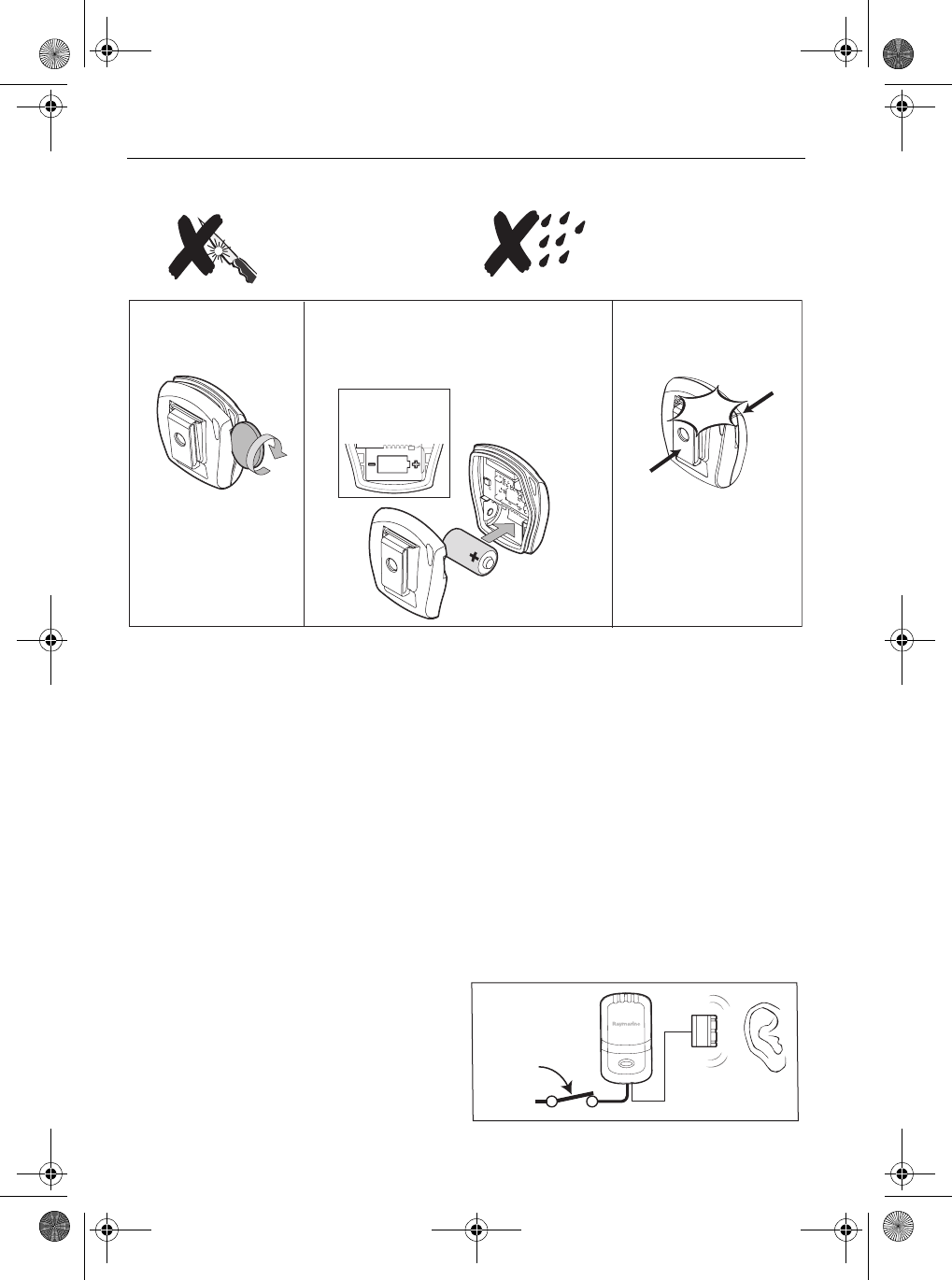
Figure 13 - Fitting Tag battery
Commissioning
Important
Before attempting to use any Tag, ensure it is registered with your Base Station. If the LED indicator on
any Tag is flashing RED, the Tag has not been registered with your Base Station, so use the procedure
on
page 12
to register the Tag.
Do NOT use any Tag that has not been registered.
Procedure
A standard LifeTag system is supplied with two Tags. These are pre-registered with the Base Station,
so if you are using only these two Tags, you can proceed with the commissioning procedure as
follows:
1. Switch on power to the Base Station and check
that the Alarm ‘chirps’ as power is applied.
Do NOT use a sharp
object to open a Tag
Replace the Tag back
and snap shut
Taking care not to disturb other
internal components, insert the
supplied CR2 3V battery.
Open the Tag
S
n
a
p
3.
CR2 3V
D8284-1
Ensure correct
polarity
Important!
1. 2.
Do NOT open a Tag in
wet or dirty conditions
12 V dc
D8989-1
87064_1.book Page 10 Thursday, April 6, 2006 2:38 PM
Draft copy 06/04/06
LifeTag Installation & Commissioning Guide 11
5. Bring the Tag back into range of the Base Station, to automatically cancel the alarm. If the alarm
does not cancel automatically, hold down the Tag button for 5 seconds then release it, to manu-
ally cancel the alarm.
Note:
You can manually cancel an alarm from any active Tag within range of the Base Station.
2. Check each Tag to ensure the LED indicator
briefly flashes GREEN once every 10 seconds,
to indicates that the Tag is ACTIVE. If a Tag is
not active, press and release the push button
to activate the Tag.
3. Take each Tag, one at a time, to every part of
the vessel to which crew members have
access, (i.e. every cabin, compartment and all
extremes of the deck). Ensure that no alarms
are initiated.
4. With the boat moored alongside, take each
Tag away from the boat and note the distance
from the Base Station at which an alarm is ini-
tiated. This should be approximately 30 feet (9
meters).
Flash
GREEN
D9034-1
D9035-1
D9037-1
87064_1.book Page 11 Thursday, April 6, 2006 2:38 PM
Draft copy 06/04/06
12 LifeTag Installation & Commissioning Guide
Tag registration & de-registration
Registering a Tag
Tags supplied with a Base Station as part of a LifeTag system, are factory-registered with the Base
Station so you do not have to carry out a registration procedure with these.
However, if you have obtained a Tag separate from your Base Station (e.g. if you have bought an extra
Tag), IT WILL NOT WORK WITH YOUR BASE STATION until you have registered the Tag with the Base
Station.
Important
You must complete the registration procedure within one minute of switching on
power to the Base Station.
To register a Tag:
1. Bring the Tag you want to register, near to the Base
Station, then switch on the power to the Base Sta-
tion.
2. IMMEDIATELY press and release Tag button, to acti-
vate (switch on) the Tag. Check that the RED indicator
is flashing.
3. Press and release the Tag button. Check that the RED
indicator lights constantly.
4. Check that within the next 15 seconds, registration
starts. This is indicated by alternate RED and GREEN
LED flashes.
Note:
If registration does not start, switch the Base Station off
and on again, then repeat steps 2 to 4.
12 V dc
D9038-1
RED LED
Flashes
D9039-1
RED LED
Lit constantly
D9040-1
Alternate
RED and
GREEN
REGISTRATION START
D9041-1
87064_1.book Page 12 Thursday, April 6, 2006 2:38 PM
Draft copy 06/04/06
LifeTag Installation & Commissioning Guide 13
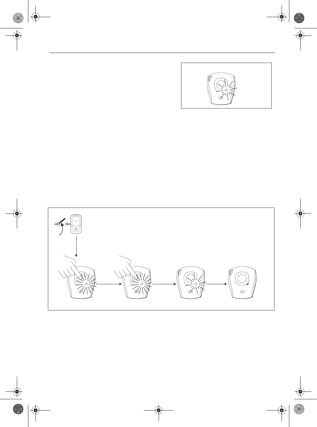
De-registering a Tag
If you want to de-register a Tag (for example, to use it with a different Base Station):
1. De-activate the Tag by switching off the associated Base Station then waiting for at least one
minute.. When the Tag is inactive, the indicator should not show any indication.
2. Hold down the Tag button, and check that:
i. The GREEN indicator lights.
ii. After 5 seconds, the RED indicator lights.
iii. After a further 5 seconds, the RED indicator flashes
The Tag is now de-registered. After a further few seconds,the Tag will automatically power down and
the indicator will be unlit.
Note:
Before you can use the Tag again, you must register it with the relevant Base Station.
5. Wait for registration to complete. This is indicated by
GREEN indicator flashing briefly once every
10 seconds. The Tag is now active (i.e. in normal oper-
ating mode) and will initiate an alarm condition in the
appropriate circumstances.
GREEN Flashes
(Tag active)
REGISTRATION COMPLETE
D9042-1
RED LED LitGREEN LED Lit
Tag
DEREGISTERED
Tag
POWER OFF
RED LED Flashes LED Unlit
5 seconds 5 seconds
60 seconds
D9043-1
87064_1.book Page 13 Thursday, April 6, 2006 2:38 PM
Draft copy 06/04/06
14 LifeTag Installation & Commissioning Guide
Raymarine UK Ltd,
Quay Point, Northarbour Road
Portsmouth, Hampshire PO6 3TD,
United Kingdom.
Tel: +44 (0) 23 9269 3611
Fax: +44 (0) 23 9269 4642
www.raymarine.com
Raymarine Inc,
21 Manchester Street, Merrimack,
New Hampshire 03054,
USA.
Tel: +1 603.881.5200
Fax: +1 603.864.4756
www.raymarine.com
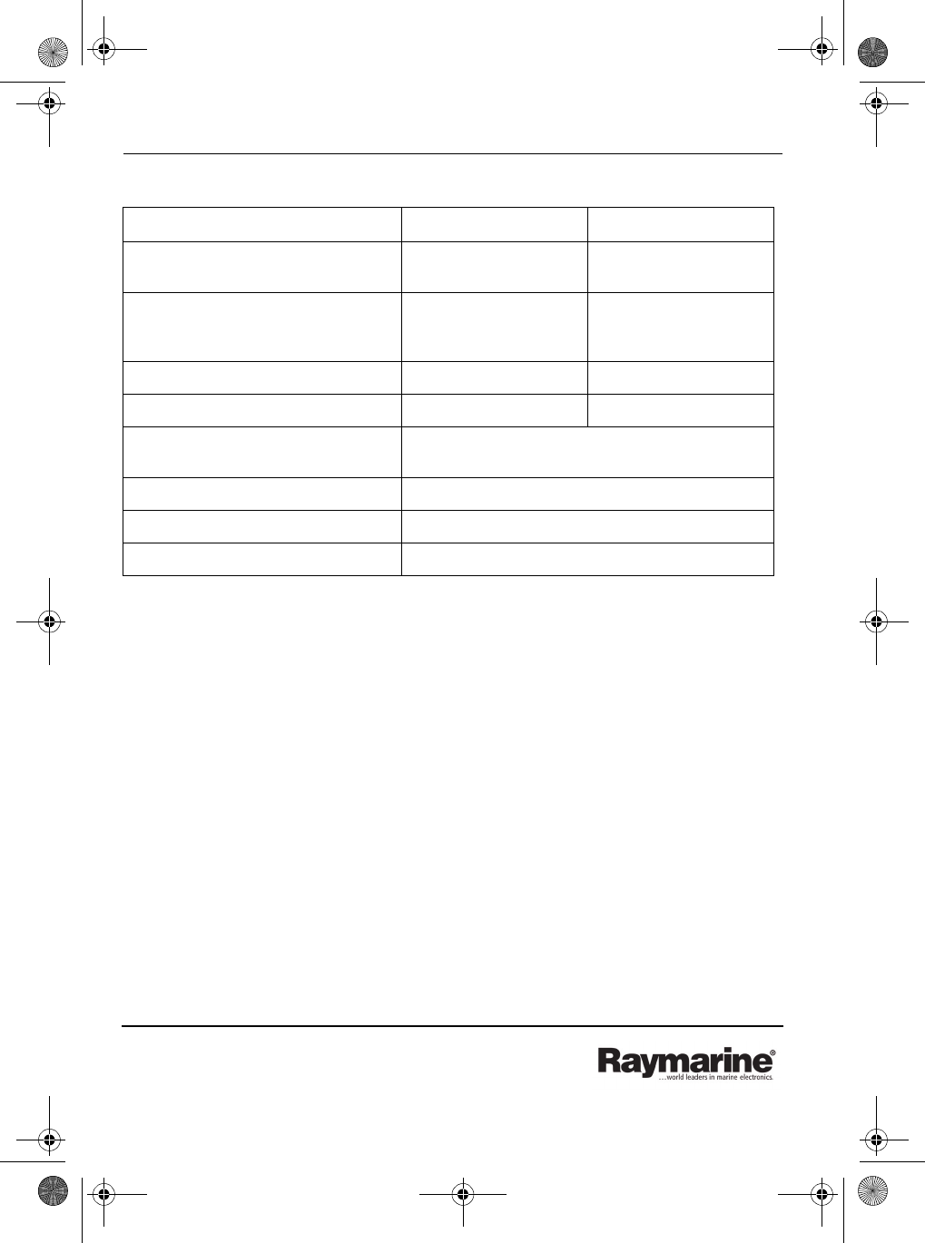
Specification
FCC Information
The LifeTag and LifeTag Base Station comply with part 15 of the FCC Rules. Operation is subject to the following
two conditions: (1) these devices may not cause harmful interference and (2) these devices must accept
interference received, including interference that may cause undesired operation.
Changes or modifications to these devices not expressly approved in writing by Raymarine could violate
compliance with FCC rules and void the user's authority to operate the equipment.
Declaration of Conformity
Raymarine UK Ltd. hereby declares that the LifeTag and LifeTag Base Stationare in compliance with the essential
requirements and other relevant provisions of the R&TTE Directive 1999/5/EC.
The original Declarations of Conformity may be viewed on the relevant product pages at www.raymarine.com.
Approvals
Parameter Base Station Tag
Power source 8 V to 12 V dc external supply Non-rechargeable, CR2 3V
lithium battery
Dimensions (overall) 2.6 in x 4.7 in x 1.4 in
(66 mm x 118 mm x 36mm)
1.93 in x 2.24 in x 1 in
(49 mm x 56.8 mm x 24.4
mm)
Ancillary switched output contact rating 200 mA at supply voltage N/A
Transmitted power (nominal) 1 mW 1 mW
Temperature: Operating:
Non-operating:
-15°C to +55°C
-20°C to +70°C
Humidity 0% to 95% non-condensing
Base Station to Tag range Typically 30 ft (9 m)
Maximum number of Tags per system 16
EU R&TTE Directive 1995/5/EC
USA FCC Part 15 FCC ID: PJ5-LTB (LifeTag Base Station) PJ5-LTT (LifeTag)
Industry Canada RSP100 ID IC4069B-LTB (LifeTag Base Station) IC4069B-LLT (LifeTag)
87064_1.book Page 14 Thursday, April 6, 2006 2:38 PM
Draft copy 06/04/06