Flir BelgiumBA MICRO-TALK Micro-Talk data bridge for use on leisure craft User Manual Installation instructions
Raymarine UK Ltd. Micro-Talk data bridge for use on leisure craft Installation instructions
Contents
- 1. Installation instructions
- 2. Addition to manual
Installation instructions

© 2016 Raymarine UK Limited
87265-1Document number:
07-2016Date:
English (en-US)
INSTALLATION
INSTRUCTIONS
Micro-Talk


Trademarkandpatentsnotice
Raymarine,Tacktick,ClearPulse,Truzoom,HSB,SeaTalk,SeaTalkhs,SeaTalkng,Micronet,Raytech,GearUp,MarineShield,Seahawk,Autohelm,Automagic,
andVisionalityareregisteredorclaimedtrademarksofRaymarineBelgium.
FLIR,DownVision,SideVision,Dragony,Quantum,Instalert,InfraredEverywhere,andTheWorld’sSixthSenseareregisteredorclaimedtrademarksofFLIR
Systems,Inc.
Allothertrademarks,tradenames,orcompanynamesreferencedhereinareusedforidenticationonlyandarethepropertyoftheirrespectiveowners.
Thisproductisprotectedbypatents,designpatents,patentspending,ordesignpatentspending.
FairUseStatement
Youmayprintnomorethanthreecopiesofthismanualforyourownuse.Youmaynotmakeanyfurthercopiesordistributeorusethemanualinanyotherwayincluding
withoutlimitationexploitingthemanualcommerciallyorgivingorsellingcopiestothirdparties.
Softwareupdates
Important:ChecktheRaymarinewebsiteforthelatestsoftwarereleasesforyourproduct.
www.raymarine.com/software
Producthandbooks
ThelatestversionsofallEnglishandtranslatedhandbooksareavailabletodownloadinPDFformatfromthewebsitewww.raymarine.com.
Pleasecheckthewebsitetoensureyouhavethelatesthandbooks.
Copyright©2016RaymarineUKLtd.Allrightsreserved.
English(en-US)
Documentnumber:87265-1
Releaselabel: AA
Commitrevision: 791
Date:07-2016

Contents
Chapter1Importantinformation.....................................7
Wateringress.............................................................7
Disclaimer.................................................................7
Suppressionferrites.....................................................7
Connectionstootherequipment.......................................8
Declarationofconformity................................................8
Productdisposal.........................................................8
Warrantyregistration.....................................................8
IMOandSOLAS.........................................................8
Technicalaccuracy.......................................................8
Chapter2Documentandproductinformation..................9
2.1Documentinformation..............................................10
Applicableproducts....................................................10
Productdocumentation................................................10
Documentillustrations.................................................10
Operationinstructions.................................................10
2.2Productoverview...................................................10
Multipledatasources(MDS)...........................................11
SeaTalkng®............................................................11
Micronet...............................................................11
2.3Networkingrestrictions.............................................11
Chapter3Planningtheinstallation................................13
3.1Installationchecklist................................................14
Schematicdiagram....................................................14
3.2Partssupplied.......................................................14
3.3Softwareupdates...................................................14
3.4T oolsrequiredforinstallation......................................15
3.5Warningsandcautions.............................................15
3.6Selectingalocation.................................................15
Micronetdevicelocationrequirements.................................15
Compasssafedistance................................................16
EMCinstallationguidelines............................................16
3.7Productdimensions................................................16
Chapter4Cablesandconnections................................17
4.1Generalcablingguidance.........................................18
Cabletypesandlength................................................18
Routingcables.........................................................18
Strainrelief............................................................18
Cableshielding........................................................18
4.2Connectionsoverview..............................................18
ConnectingSeaTalkng®cables........................................19
SeaTalkng®productloading...........................................19
4.3SeaT alkng®powersupply.........................................19
SeaTalkng®powerconnectionpoint...................................19
In-linefuseandthermalbreakerratings................................19
SeaTalkng®systemloading...........................................20
Powerdistribution—SeaTalkng®.....................................20
Sharingabreaker......................................................21
4.4Networkexamples..................................................21
4.5Autonetworking.....................................................22
Autonetworking—compatibleMicronetdisplays.......................22
PerformingAutonetworking............................................23
Chapter5Installation...................................................25
5.1Surfacemounting...................................................26
5

5.2Polemounting.......................................................26
5.3SurfacemountingusingtheDeckmountingkit.................27
5.4BracketmountingusingtheDeckmountingkit.................28
5.5SurfacemountingusingtheRiser................................28
5.6Lockingandreleasingtheunit....................................29
Chapter6Systemchecksandtroubleshooting...............31
6.1Troubleshooting.....................................................32
6.2LEDDiagnostics....................................................33
Chapter7Maintenance.................................................35
7.1Serviceandmaintenance..........................................36
7.2Routineequipmentchecks........................................36
7.3Productcleaning....................................................36
Chapter8Technicalsupport.........................................37
8.1Raymarineproductsupportandservicing.......................38
Viewingproductinformation...........................................38
8.2Learningresources.................................................39
Chapter9Technicalspecication..................................41
9.1T echnicalspecication.............................................42
Chapter10Sparesandaccessories...............................43
10.1Accessories........................................................44
10.2SeaT alkng®cablingcomponents.................................44
10.3SeaT alkng®cablesandaccessories.............................44
AppendixANMEA2000PGNsupport............................47
6
Chapter1:Important
information
Warning:Product
installationandoperation
•Thisproductmustbeinstalledand
operatedinaccordancewiththe
instructionsprovided.Failuretodoso
couldresultinpersonalinjury,damage
toyourvesseland/orpoorproduct
performance.
•Raymarinerecommendscertied
installationbyaRaymarineapproved
installer.Acertiedinstallationqualies
forenhancedproductwarrantybenets.
ContactyourRaymarinedealerfor
furtherdetails,andrefertotheseparate
warrantydocumentpackedwithyour
product.
Warning:Potentialignition
source
ThisproductisNOTapprovedforusein
hazardous/ammableatmospheres.Do
NOTinstallinahazardous/ammable
atmosphere(suchasinanengineroomor
nearfueltanks).
Warning:Switchoffpower
supply
Ensurethevessel’spowersupplyis
switchedOFFbeforestartingtoinstallthis
product.DoNOTconnectordisconnect
equipmentwiththepowerswitchedon,
unlessinstructedinthisdocument.
Warning:Powersupply
voltage
Connectingthisproducttoavoltagesupply
greaterthanthespeciedmaximumrating
maycausepermanentdamagetotheunit.
RefertotheTechnicalspecicationsection
forvoltagerating.
Caution:Powersupply
protection
Wheninstallingthisproductensurethe
powersourceisadequatelyprotectedby
meansofasuitably-ratedfuseorautomatic
circuitbreaker.
Caution:Productcleaning
Whencleaningproducts:
•Ifyourproductincludesadisplayscreen,
doNOTwipethescreenwithadrycloth,
asthiscouldscratchthescreencoating.
•DoNOTuseabrasive,oracidor
ammoniabasedproducts.
•DoNOTuseajetwash.
Caution:Serviceand
maintenance
Thisproductcontainsnouserserviceable
components.Pleasereferallmaintenance
andrepairtoauthorizedRaymarine
dealers.Unauthorizedrepairmayaffect
yourwarranty.
Wateringress
Wateringressdisclaimer
Althoughthewaterproofratingcapacityofthis
productmeetsthestatedIPXstandard(refertothe
product’sTechnicalSpecication),waterintrusionand
subsequentequipmentfailuremayoccuriftheproduct
issubjectedtocommercialhigh-pressurewashing.
Raymarinewillnotwarrantproductssubjectedto
high-pressurewashing.
Disclaimer
Raymarinedoesnotwarrantthatthisproductis
error-freeorthatitiscompatiblewithproducts
manufacturedbyanypersonorentityotherthan
Raymarine.
Raymarineisnotresponsiblefordamagesorinjuries
causedbyyouruseorinabilitytousetheproduct,bythe
interactionoftheproductwithproductsmanufactured
byothers,orbyerrorsininformationutilizedbythe
productsuppliedbythirdparties.
Suppressionferrites
•Raymarinecablesmaybepre-ttedorsuppliedwith
suppressionferrites.Theseareimportantforcorrect
EMCperformance.Ifferritesaresuppliedseparately
tothecables(i.e.notpre-tted),youmusttthe
suppliedferrites,usingthesuppliedinstructions.
•Ifaferritehastoberemovedforanypurpose(e.g.
installationormaintenance),itmustbereplacedin
theoriginalpositionbeforetheproductisused.
•Useonlyferritesofthecorrecttype,suppliedby
Raymarineoritsauthorizeddealers.
•Whereaninstallationrequiresmultipleferritestobe
addedtoacable,additionalcableclipsshouldbe
usedtopreventstressontheconnectorsduetothe
extraweightofthecable.
Importantinformation7

Connectionstoother
equipment
Requirementforferritesonnon-Raymarinecables
IfyourRaymarineequipmentistobeconnectedtoother
equipmentusingacablenotsuppliedbyRaymarine,a
suppressionferriteMUSTalwaysbeattachedtothe
cableneartheRaymarineunit.
Declarationofconformity
RaymarineUKLtd.declaresthatthisproductis
compliantwiththeessentialrequirementsofEMC
directive2004/108/EC.
TheoriginalDeclarationofConformitycerticate
maybeviewedontherelevantproductpageat
www.raymarine.com.
Productdisposal
DisposeofthisproductinaccordancewiththeWEEE
Directive.
TheWasteElectricalandElectronicEquipment
(WEEE)Directiverequirestherecyclingofwaste
electricalandelectronicequipment.
Warrantyregistration
ToregisteryourRaymarineproductownership,please
visitwww.raymarine.comandregisteronline.
Itisimportantthatyouregisteryourproducttoreceive
fullwarrantybenets.Yourunitpackageincludesa
barcodelabelindicatingtheserialnumberoftheunit.
Youwillneedthisserialnumberwhenregisteringyour
productonline.Youshouldretainthelabelforfuture
reference.
IMOandSOLAS
Theequipmentdescribedwithinthisdocumentis
intendedforuseonleisuremarineboatsandworkboats
NOTcoveredbyInternationalMaritimeOrganization
(IMO)andSafetyofLifeatSea(SOLAS)Carriage
Regulations.
Technicalaccuracy
Tothebestofourknowledge,theinformationinthis
documentwascorrectatthetimeitwasproduced.
However,Raymarinecannotacceptliabilityforany
inaccuraciesoromissionsitmaycontain.Inaddition,
ourpolicyofcontinuousproductimprovementmay
changespecicationswithoutnotice.Asaresult,
Raymarinecannotacceptliabilityforanydifferences
betweentheproductandthisdocument.Please
checktheRaymarinewebsite(www.raymarine.com)to
ensureyouhavethemostup-to-dateversion(s)ofthe
documentationforyourproduct.
8

2.1Documentinformation
Thisdocumentcontainsimportantinformationrelated
totheinstallationofyourRaymarineproduct.
Thedocumentincludesinformationtohelpyou:
•planyourinstallationandensureyouhaveallthe
necessaryequipment;
•installandconnectyourproductaspartofawider
systemofconnectedmarineelectronics;
•troubleshootproblemsandobtaintechnicalsupport
ifrequired.
ThisandotherRaymarineproductdocuments
areavailabletodownloadinPDFformatfrom
www.raymarine.com.
Applicableproducts
Thisdocumentisapplicabletothefollowingproducts:
Part
numberNameDescription
E70361Micro-TalkMicronet
(Wireless)to
SeaTalkng®
gateway
Productdocumentation
Thefollowingdocumentationisapplicabletoyour
product:
Description
Part
number
Micro-TalkInstallationinstructions
InstallationofaMicro-Talkgatewayand
connectiontoawidersystemofmarine
electronics.
87265/
88066
Micro-Talkmountingtemplate
TemplateforsurfacemountingtheMicro-Talk
gateway.
87272
Documentillustrations
Yourproductmaydifferslightlyfromthatshowninthe
illustrationsinthisdocument,dependingonproduct
variantanddateofmanufacture.
Allimagesareprovidedforillustrationpurposesonly.
Operationinstructions
Fordetailedoperationinstructionsforyourproduct,
refertothedocumentationthataccompaniesyour
display.
2.2Productoverview
TheMicro-TalkgatewaybridgesdatabetweenMicronet
(wireless)andSeaTalkng®networks.Whenusedin
conjunctionwithaSeaTalk®toSeaT alkng®converter
thedatacanalsobebridgedontotheSeaT alk®
networkordevices.
TheMicro-Talkgatewayhasthefollowingfeatures:
•BridgesdatafromMicronettoSeaT alkng®
•BridgesdatafromSeaTalkng®toMicronet
•Pole,RailorSurfaceorBracketmountableusing
optionalmountingkits
•NMEA2000compliant
•Lowpowerconsumption
•12Vdcoperation(24Vprotection)
•WaterprooftoIPx6andIPx7
ThefollowingdatacanbebridgedbytheMicro-T alk
gateway:
Data
Micro-Talkto
SeaTalkng®
SeaTalkng®to
Micro-Talk
Wind
Mastrotation
Depth
(1)or(2)
10
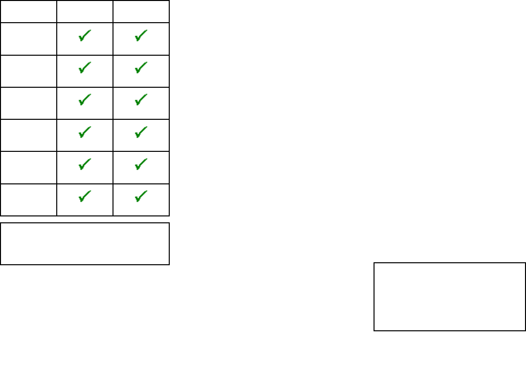
Data
Micro-Talkto
SeaTalkng®
SeaTalkng®to
Micro-Talk
Speed
(1)or(2)
Temperature
(1)or(2)
Heading
(1)or(2)
GPS
(2)
Time&Date
(2)
Navigationdata
(2)
Note:
•(1)RequiresT121Wirelesshulltransmitter.
•(2)RequiresT122NMEA0183wirelessinterface.
Multipledatasources(MDS)
TheMicro-T alkgatewayisMDScompliant.Ifadata
typeisavailableontheMicronetnetworkthenthe
gatewaywillbeselectableasadatasource,forthat
datatype,fromSeaT alkng®displays.
Ininstallationswheremultiplesourcesofthesame
datatypeexistontheMicronetnetwork,thedata
sourcethatisusedbythegatewayandtransmittedon
toSeaT alkng®willbethesamedatasourcethatis
displayedonMicronetdisplays.
Ininstallationswherethesamedatatypesexistonboth
networksthentheMDSselecteddatasourcewillbe
shownondisplaysonbothnetworks.
IfMDSissettoAutothenthegatewaywillbethe
preferreddatasource.
SeaTalkng®
SeaTalkng®(NextGeneration)isanenhancedprotocol
forconnectionofcompatiblemarineinstrumentsand
equipment.ItreplacestheolderSeaTalkandSeaT alk2
protocols.
SeaTalkng®utilizesasinglebackbonetowhich
compatibleequipmentconnectusingaspur.Dataand
powerarecarriedwithinthebackbone.Devicesthat
havealowdrawcanbepoweredfromthenetwork,
althoughhighcurrentequipmentwillneedtohavea
separatepowerconnection.
SeaTalkng®isaproprietaryextensiontoNMEA2000
andtheprovenCANbustechnology.Compatible
NMEA2000andSeaT alkandSeaTalk2devicescan
alsobeconnectedusingtheappropriateinterfacesor
adaptorcablesasrequired.
Micronet
MicronetisaproprietarywirelessRadioFrequency(RF)
networkprotocolcompatiblewithRaymarine’swireless
rangeofinstrumentdisplaysandtransducers.
Micronetcanbeusedtoconnectupto32compatible
devicestogethertocreateawirelessmarineelectronics
network.Micronetproductscanoperateon1of2
frequenciesdependingongeographiclocation:
•869.8MHzforproductsoperatingintheUK,Europe
orAfrica
•915.9MHzforproductsoperatingintheUSA,
Canada,SouthAmericaandAustralia
MicronetproductscomplywiththerelevantISM
regulationsandareexemptfromlicensingineachof
theseterritories.
2.3Networkingrestrictions
Toensurereliablesystemoperation,certainrestrictions
mustbeadheredtowhenusingtheMicro-Talkgateway.
•Wirelessinterface(NMEA0183)Whenthe
Micro-TalkgatewayisusedinaMicronetnetworkthat
hasaWirelessinterface(T122)present,toprevent
datalooping,youmustensurethattheWireless
interface’sNMEA0183input/outputconnectionsare
NOTconnectedtoanMFDoranNMEA0183to
SeaTalkng®converterthatisconnectedtothesame
networkasthegateway.
•MultipleMicro-TalkgatewaysItisrecommended
thatonly1Micro-Talkgatewayisusedper
SeaTalkng®network.Afterpoweringupifagateway
detectsanothergatewayitwillshutitselfdown.Itis
recommendedthatonly1Micro-T alkgatewayisused
perMicronetnetwork.BridgingmultipleSeaT alkng®
networksusingMicronetisNOTrecommended.
•DatadampingTheMicronetprotocolapplies
dampingtodataatsourcesothatthedatatransmitted
onthenetworkismorestable/consistent.On
SeaTalkng®networksthedataisdampedbythe
displays.Thereisthereforariskthatdatacanbe
doubledamped,onceatsourceonMicronetand
thenagainbytheSeaT alkng®display.Tominimize
theeffectofdoubledamping,whenthegatewayis
poweredupitwillautomaticallysendamessagetoall
Micronetdisplaysandsettheirdampingtothelowest
level.ThismayresultinMicronetdisplaysshowing
rapidlychangingdata.
Note:Theremaybesmalldifferencesin
thedatashownonMicronetdisplaystothat
shownonSeaT alkng®displaysduetothe
effectsofdamping.Youcanmanuallyalterthe
dampingsettingsonyourdisplaystoprovide
amorestable/consistentreading.Damping
settingsonMicronetdisplaysareresetwhen
thesystemispowercycled.
Documentandproductinformation11

12

3.1Installationchecklist
Installationincludesthefollowingactivities:
InstallationTask
1Planyoursystem.
2Obtainallrequiredequipmentandtools.
3Siteallequipment.
4Routeallcables.
5Drillcableandmountingholes.
6Makeallconnectionsintoequipment.
7Secureallequipmentinplace.
8Poweronandtestthesystem.
Schematicdiagram
Aschematicdiagramisanessentialpartofplanning
anyinstallation.Itisalsousefulforanyfutureadditions
ormaintenanceofthesystem.Thediagramshould
include:
•Locationofallcomponents.
•Connectors,cabletypes,routesandlengths.
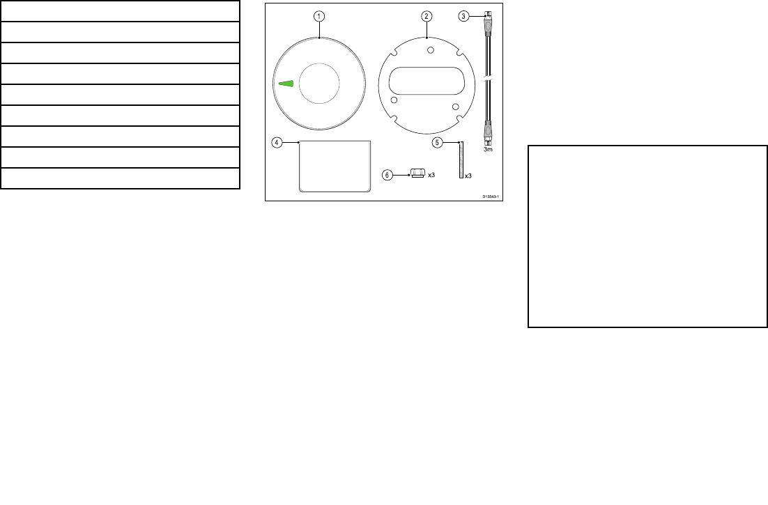
3.2Partssupplied
Thefollowingpartsaresuppliedwithyourproduct.
1.Unit
2.Mountingseal
3.3m(9.84ft)SeaT alkng®spurcable
4.Documentation
5.M4x40mmThreadedstudsx3(usedforsurface
mounting)
6.Fingernutsx3(usedforsurfacemounting)
Unpackyourproductcarefullytopreventdamageor
lossofparts,checktheboxcontentsagainstthelist
above.Retainthepackaginganddocumentationfor
futurereference.
3.3Softwareupdates
Thesoftwarerunningontheproductcanbeupdated.
•Raymarineperiodicallyreleasessoftwareupdatesto
improveproductperformanceandaddnewfeatures.
•Youcanupdatethesoftwareforyourproductusinga
connectedandcompatiblemultifunctiondisplay.
•Refertowww.raymarine.com/software/forthelatest
softwareupdatesandthesoftwareupdateprocedure
foryourproduct.
•Ifindoubtastothecorrectprocedureforupdating
yourproductsoftware,refertoyourdealeror
Raymarinetechnicalsupport.
Caution:Installingsoftware
updates
Thesoftwareupdateprocessiscarried
outatyourownrisk.Beforeinitiatingthe
updateprocessensureyouhavebacked
upanyimportantles.
Ensurethattheunithasareliablepower
supplyandthattheupdateprocessisnot
interrupted.
Damagecausedbyincompleteupdates
arenotcoveredbyRaymarinewarranty.
Bydownloadingthesoftwareupdate
package,youagreetotheseterms.
14
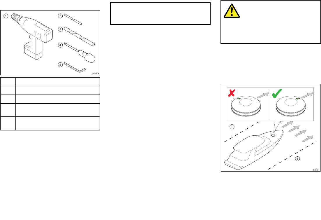
3.4Toolsrequiredfor
installation
1Powerdrill
24mm(11/64)drillbit(forxingstuds)
322mm(forcableholewhensurfacemounting)
4Pozi-drivescrewdriver(onlyrequiredforPolemount
installations)
5Size4(2.5mm)HexKey(onlyrequiredforPole
mountinstallations)
3.5Warningsandcautions
Important:Beforeproceeding,ensurethatyouhave
readandunderstoodthewarningsandcautions
providedintheChapter1Importantinformation
sectionofthisdocument.
3.6Selectingalocation
Warning:Potentialignition
source
ThisproductisNOTapprovedforusein
hazardous/ammableatmospheres.Do
NOTinstallinahazardous/ammable
atmosphere(suchasinanengineroomor
nearfueltanks).
Micronetdevicelocation
requirements
Yourunitincludesawirelesstransceiverthatutilizesthe
Micronetnetworkingprotocol.Theproduct’swireless
performanceshouldbecheckedatthedesiredlocation
beforedrillinganymountingholes.
Foroptimumperformancetheproductshouldbe
installedabovedecks,onahorizontallysurfacewiththe
LED‘arrow’pointingtowardsthebowofthevessel.
Whenplanningtheinstallationlocation,alsoconsider
thefollowing:
•Theproductshouldhaveaclearlineofsighttothe
Micronetproductsitwillconnectwith.Rangefor
Planningtheinstallation15
unobstructedlineofsightisupto150m(492ft),if
thelineofsightisobstructedbyabulkheadorother
objectthisrangecanbedrasticallyreduced.
•Theunitshouldbemountedatleast1m(3ft)away
fromdevicesthatmaycauseinterference,suchasa
compass,motors,generators,VHFradio,andany
othertransmittersorreceivers.
•Choosealocationwheretheunitwillbesafefrom
physicaldamageandexcessivevibration.
•Choosealocationwherenoloadorforcemaybeput
ontheproduct.
•Mountawayfromanysourceofheatorpotential
ammablehazards,suchasfuelvapor.
•Theproductshouldbemountedinalocationwhere
thediagnosticsLEDisviewable.
Note:DoNOTmountonaCarbon,Steelor
Aluminiumsurface,asthismaycauseinterferenceof
thewirelesssignal,instead,inthesecircumstances,
mountusingtheoptionalPolemountingorDeck
mountingkit.
Compasssafedistance
Topreventpotentialinterferencewiththevessel's
magneticcompasses,ensureanadequatedistanceis
maintainedfromtheproduct.
Whenchoosingasuitablelocationfortheproductyou
shouldaimtomaintainthemaximumpossibledistance
fromanycompasses.Typicallythisdistanceshouldbe
atleast1m(3ft)inalldirections.Howeverforsome
smallervesselsitmaynotbepossibletolocatethe
productthisfarawayfromacompass.Inthissituation,
whenchoosingtheinstallationlocationforyourproduct,
ensurethatthecompassisnotaffectedbytheproduct
whenitisinapoweredstate.
EMCinstallationguidelines
Raymarineequipmentandaccessoriesconformto
theappropriateElectromagneticCompatibility(EMC)
regulations,tominimizeelectromagneticinterference
betweenequipmentandminimizetheeffectsuch
interferencecouldhaveontheperformanceofyour
system
CorrectinstallationisrequiredtoensurethatEMC
performanceisnotcompromised.
Note:InareasofextremeEMCinterference,
someslightinterferencemaybenoticedonthe
product.Wherethisoccurstheproductandthe
sourceoftheinterferenceshouldbeseparatedby
agreaterdistance.
ForoptimumEMCperformancewerecommendthat
whereverpossible:
•Raymarineequipmentandcablesconnectedtoitare:
–Atleast1m(3ft)fromanyequipmenttransmitting
orcablescarryingradiosignalse.g.VHFradios,
cablesandantennas.InthecaseofSSBradios,
thedistanceshouldbeincreasedto7ft(2m).
–Morethan2m(7ft)fromthepathofaradarbeam.
Aradarbeamcannormallybeassumedtospread
20degreesaboveandbelowtheradiatingelement.
•Theproductissuppliedfromaseparatebatteryfrom
thatusedforenginestart.Thisisimportanttoprevent
erraticbehavioranddatalosswhichcanoccurifthe
enginestartdoesnothaveaseparatebattery.
•Raymarinespeciedcablesareused.
•Cablesarenotcutorextended,unlessdoingsois
detailedintheinstallationmanual.
Note:Whereconstraintsontheinstallation
preventanyoftheaboverecommendations,
alwaysensurethemaximumpossibleseparation
betweendifferentitemsofelectricalequipment,to
providethebestconditionsforEMCperformance
throughouttheinstallation
3.7Productdimensions
16

4.1Generalcablingguidance
Cabletypesandlength
Itisimportanttousecablesoftheappropriatetypeand
length
•Unlessotherwisestateduseonlystandardcablesof
thecorrecttype,suppliedbyRaymarine.
•Ensurethatanynon-Raymarinecablesareofthe
correctqualityandgauge.Forexample,longer
powercablerunsmayrequirelargerwiregaugesto
minimizevoltagedropalongtherun.
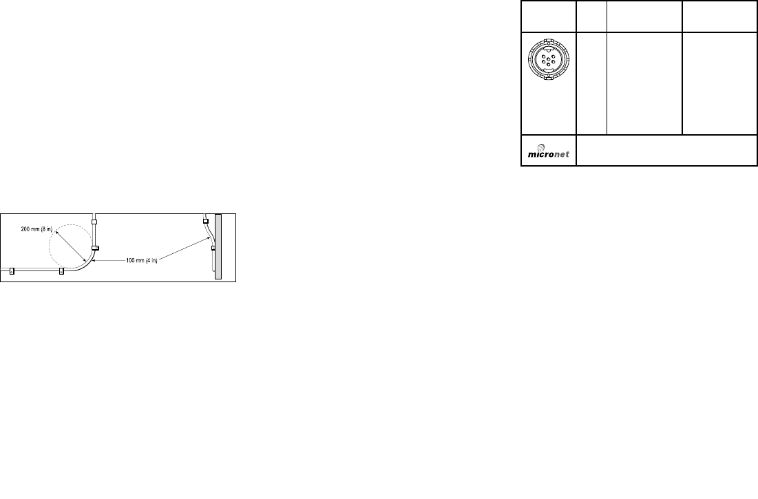
Routingcables
Cablesmustberoutedcorrectly,tomaximize
performanceandprolongcablelife.
•DoNOTbendcablesexcessively.Wherever
possible,ensureaminimumbenddiameterof200
mm(8in)/minimumbendradiusof100mm(4in).
•Protectallcablesfromphysicaldamageand
exposuretoheat.Usetrunkingorconduitwhere
possible.DoNOTruncablesthroughbilgesor
doorways,orclosetomovingorhotobjects.
•Securecablesinplaceusingtie-wrapsorlacing
twine.Coilanyextracableandtieitoutoftheway.
•Whereacablepassesthroughanexposedbulkhead
ordeckhead,useasuitablewatertightfeed-through.
•DoNOTruncablesneartoenginesoruorescent
lights.
Alwaysroutedatacablesasfarawayaspossiblefrom:
•otherequipmentandcables,
•highcurrentcarryingACandDCpowerlines,
•antennae.
Strainrelief
Ensureadequatestrainreliefisprovided.Protect
connectorsfromstrainandensuretheywillnotpullout
underextremeseaconditions.
Cableshielding
Ensurethatalldatacablesareproperlyshieldedthat
thecableshieldingisintact(e.g.hasn’tbeenscraped
offbybeingsqueezedthroughatightarea).
4.2Connectionsoverview
Yourproductincludesthefollowingconnections.
Connec-
tionQtyConnectsto:Suitablecables
11.SeaT alkng®
backbone
2.NMEA2000
backbone
1.SeaTalkng®
spurcables
2.SeaTalkng®
to
DeviceNet
adaptor
cable
(A06045)
Canconnectupto32CompatibleMicronet
(wireless)devicessimultaneously.
18
ConnectingSeaTalkng®cables
1.Rotatethelockingcollarontheunittotheunlocked
position.
2.Ensurethecable’sconnectoriscorrectlyoriented.
3.Fullyinsertthecableconnector.
4.Rotatelockingcollarclockwise(2clicks)untilitisin
thelockedposition.
SeaTalkng®productloading
Thenumberofproductsthatcanbeconnectedto
aSeaT alkng®backbonedependsonthepower
consumptionofeachproductandthephysicaloverall
lengthofthebackbone.
SeaTalkng®productshaveaLoadEquivalency
Number(LEN),whichindicatestheproduct’spower
consumption.TheLENforeachproductcanbefound
intheproduct’sTechnicalSpecication.
4.3SeaTalkng®powersupply
PowerissuppliedtotheproductovertheSeaTalkng®
backbone.
ASeaT alkng®backbonerequiresone12Vdcpower
supply,connectedtotheSeaT alkng®backbone.This
canbeprovidedby:
•abattery(1),viathedistributionpanel,
•anAutopilotControlUnit(ACU)(2),
•anSPXcoursecomputer(2),
•for24Vvesselsa5amp,regulated,continuous24V
dcto12Vdcconverterisrequired.
Note:
•(1)Thebatteryusedforstartingthevessel’s
engine(s)shouldNOTbeusedtopowerthe
SeaTalkng®backboneasthiscancausesudden
voltagedrops,whentheenginesarestarted.
•(2)TheACU-100andSPX-5cannotbeusedto
powertheSeaTalkng®backbone.
SeaTalkng®powerconnectionpoint
Smallsystems
Ifthebackbonelengthis60m(197ft)orless,the
powerconnectionpointmaybeconnectedatanypoint
inthebackbone.
Largesystems
Ifthebackbonelengthisgreaterthan60m(197ft),
thepowerconnectionpointshouldbeconnectedata
pointthatcreatesabalancedcurrentdrawfromeach
sideofthebackbone.TheLoadEquivalencyNumber
(LEN)isusedtodeterminethepowerconnectionpoint
forthesystem.
IntheexampleabovethesystemhasanoverallLENof
10,sotheoptimumconnectionpointwouldbetohave
5LENeithersideoftheconnectionpoint.
In-linefuseandthermalbreaker
ratings
TheSeaT alkng®network’spowersupplyrequiresan
in-linefuseorthermalbreakertobetted.
In-linefuseratingThermalbreakerrating
5A3A(ifonlyconnectingone
device)
Note:Thesuitablefuseratingforthethermal
breakerisdependentonthenumberofdevicesyou
areconnecting.Ifindoubtconsultanauthorized
Raymarinedealer.
Cablesandconnections19
SeaTalkng®systemloading
Themaximumloading/LENforaSeaTalkng®system
dependsonthelengthofthebackbone.
LoadingtypeBackbonelengthTotalLEN
Unbalanced20m(66ft)40
Unbalanced40m(131ft)20
Unbalanced60m(197ft)14
Balanced60m(197ft)or
less
100
Balanced80m(262ft)84
Balanced100m(328ft)60
Balanced120m(394ft)50
Balanced140mto160m
(459ftto525ft)
40
Balanced180mto200m
(591ftto656ft)
32
Powerdistribution—SeaTalkng®
Recommendationsandbestpractice.
•OnlyuseapprovedSeaT alkng®powercables.Do
NOTuseapowercabledesignedfor,orsupplied
with,adifferentproduct.
•Seebelowformoreinformationonimplementation
forsomecommonpowerdistributionscenarios.
Important:Whenplanningandwiring,takeinto
considerationotherproductsinyoursystem,someof
which(e.g.sonarmodules)mayplacelargepower
demandpeaksonthevessel’selectricalsystem.
Note:Theinformationprovidedbelowisfor
guidanceonly,tohelpprotectyourproduct.Itcovers
commonvesselpowerarrangements,butdoes
NOTcovereveryscenario.Ifyouareunsurehow
toprovidethecorrectlevelofprotection,please
consultanauthorizedRaymarinedealerorasuitably
qualiedprofessionalmarineelectrician.
Implementation—directconnectiontobattery
•SeaTalkng®powercablesmaybeconnecteddirectly
tothevessel'sbattery,viaasuitablyratedfuseor
breaker.
•YouMUSTtasuitablyratedfuseorbreakerbetween
theredwireandthebattery’spositiveterminal.
•Refertotheinlinefuseratingsprovidedinthe
product’sdocumentation.
•Ifyouneedtoextendthelengthofthepowercable,
ensureyouusesuitablyratedcableandthatsufcient
power(12Vdc)isavailableattheSeaTalkng®
backbone’spowerconnection.
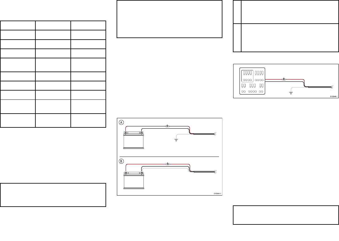
ABatteryconnectionscenarioA:suitableforavesselwitha
commonRFgroundpoint.Inthisscenario,ifyourproduct’s
powercableissuppliedwithaseparatedrainwirethenit
shouldbeconnectedtothevessel’scommongroundpoint.
BBatteryconnectionscenarioB:suitableforavesselwithout
acommongroundingpoint.Inthiscase,ifyourproduct’s
powercableissuppliedwithaseparatedrainwirethen
itshouldbeconnecteddirectlytothebattery’snegative
terminal.
Implementation—connectiontodistributionpanel
•Alternatively,theSeaTalkng®powercablemaybe
connectedtoasuitablebreakerorswitchonthe
vessel'sdistributionpanelorfactory-ttedpower
distributionpoint.
•Thedistributionpointshouldbefedfromthevessel’s
primarypowersourceby8AWG(8.36mm2)cable.
•Ideally,allequipmentshouldbewiredtoindividual
suitably-ratedthermalbreakersorfuses,with
appropriatecircuitprotection.Wherethisisnot
possibleandmorethan1itemofequipmentsharesa
breaker,useindividualin-linefusesforeachpower
circuittoprovidethenecessaryprotection.
•Inallcases,observetherecommendedbreaker/
fuseratingsprovidedintheproduct’sdocumentation.
•Ifyouneedtoextendthelengthofthepowercable,
ensureyouusesuitablyratedcableandthatsufcient
power(12Vdc)isavailableattheSeaTalkng®
backbone’spowerconnection.
Important:Beawarethatthesuitablefuserating
forthethermalbreakerorfuseisdependentonthe
numberofdevicesyouareconnecting.
20
Moreinformation
Raymarinerecommendsthatbestpracticeisobserved
inallvesselelectricalinstallations,asdetailedinthe
followingstandards:
•BMEACodeofPracticeforElectricalandElectronic
InstallationsinBoats
•NMEA0400InstallationStandard
•ABYCE-11AC&DCElectricalSystemsonBoats
•ABYCA-31BatterychargersandInverters
•ABYCTE-4LightningProtection
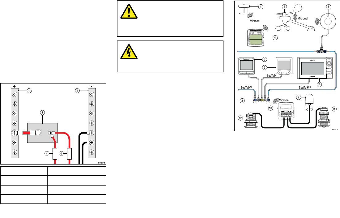
Sharingabreaker
Wheremorethan1pieceofequipmentsharesa
breakeryoumustprovideprotectionfortheindividual
circuits.E.g.byconnectinganin-linefuseforeach
powercircuit.
1Positive(+)bar
2Negative(-)bar
3Circuitbreaker
4Fuse
Wherepossible,connectindividualitemsofequipment
toindividualcircuitbreakers.Wherethisisnotpossible,
useindividualin-linefusestoprovidethenecessary
protection.
Warning:Product
grounding
Beforeapplyingpowertothisproduct,
ensureithasbeencorrectlygrounded,in
accordancewiththeinstructionsprovided.
Warning:Positiveground
systems
Donotconnectthisunittoasystemwhich
haspositivegrounding.
4.4Networkexamples
Theillustrationsbelowareprovidedasexamplesonly.
Examplesystemwithwirelesshulltransmitter
1.Mastrotationsensor
2.MicronetWindVane
3.Micro-Talkgateway
4.Wirelessinstrument
5.SeaTalkng®instrument
6.SeaTalkPilotController
7.SeaTalkng®MFD
8.SeaTalktoSeaT alkng®converter
9.T909Compasstransducer
10.Wirelesshulltransmitter
Cablesandconnections21
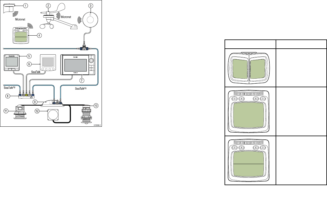
11.Depthtransducer
12.Speedandtemperaturetransducer
ExamplesystemwithiTC-5
1.Mastrotationsensor
2.MicronetWindVane
3.Micro-Talkgateway
4.Wirelessinstrument
5.SeaTalkng®instrument
6.SeaTalkPilotController
7.SeaTalkng®MFD
8.SeaTalktoSeaT alkng®converter
9.iTC-5
10.Depthtransducer
11.Speedandtemperaturetransducer
12.SeaTalkng®headingsource(e.g.Fluxgate
compassorEVsensor.)
4.5Autonetworking
Micronetwirelessproductsarenetworkedtogether
usingtheAutonetworkingprocedure.
Autonetworkingconnectscompatiblewirelessproducts,
withinrange,tothesameMicronetnetwork.
Autonetworking—compatible
Micronetdisplays
Autonetworkingcanbeinitiatedusingoneofthe
compatibleMicronetdisplaysshownbelow.
ProductDescription
T070RaceMasterDisplay
T110Multifunctionwireless
display
T111Multifunctionwireless
dualdisplay
22
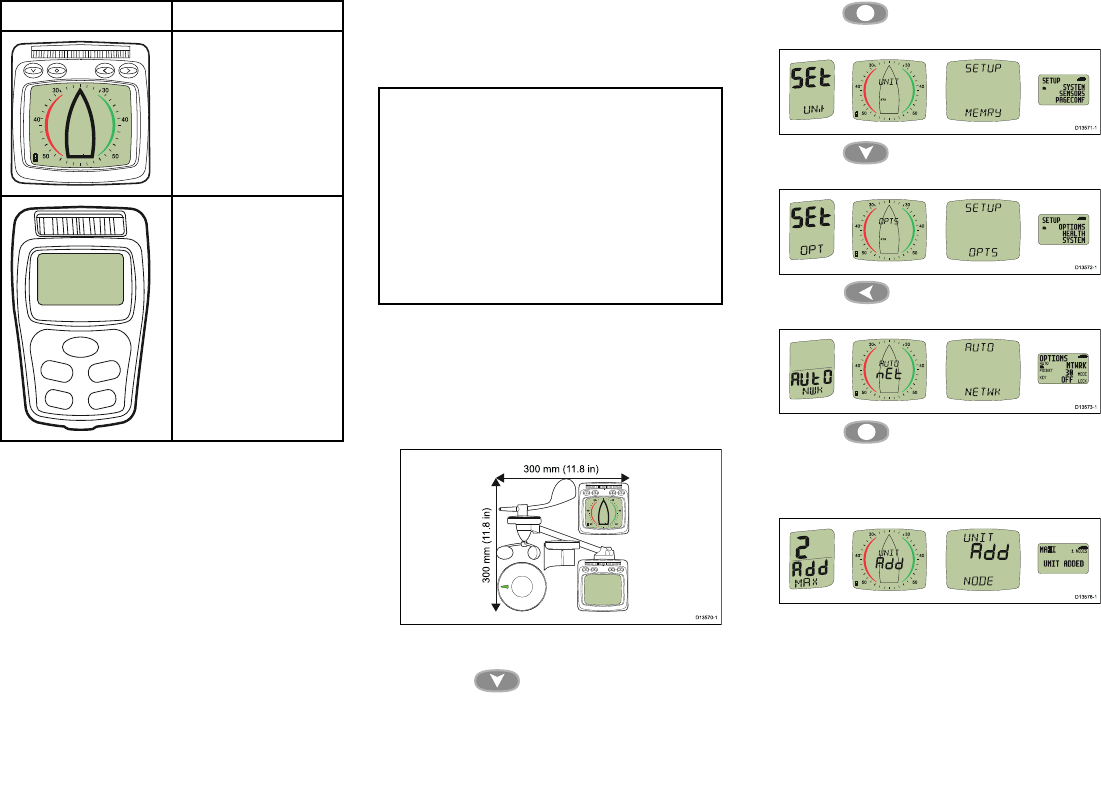
ProductDescription
T112Multifunctionwireless
analoguedisplay
T113Multifunctionwireless
remotedisplay
PerformingAutonetworking
FollowthestepsbelowtoaddnewMicronetproducts
toanexistingsystem,orcreateanewsystemfrom
multipleboxes.
Note:
•Autonetworkingshouldbeperformedbeforenew
productsaremounted.
•ThefollowingprocedureisNOTrequiredwhen
creatinganewsystemwithproductsthathave
beensuppliedinasinglebox.
•Youwillneedtochooseadisplaycapableof
initiatingAutonetworking.
•Ifyouhaveanexistingsystemthenacapable
displayfromthissystemshouldbechosen.
1.Connectproductsthatrequireanexternalpower
sourcetoa12Vdcpowersupply.
2.PlaceallNewproductswithin300mm(11.8in)ofthe
displayyouhavechosentoperformAutonetworking.
Existingnetworkedproductsdonotneedtobe
included.
3.Ensureallproductsarepoweredoff.
4.Poweronthechosendisplay,bypressingand
holdingthe Down/Powerbuttonfor2
seconds.
5.Ensurethechosendisplayisnotshowinga‘Racer
Timer’or‘WindShift’page.
6.Pressthe SetUpbuttonfor2secondsto
displaytheSetupmenu.
7.Pressthe Down/Powerbuttonuntilthe
Optionspageisdisplayed.
8.Pressthe Leftbuttontodisplaythe
Autonetworkingpage.
9.Pressthe Setupbuttontobeginthe
Autonetworkingprocedure.
Acountdownwillbeginandthechosendisplay
shows‘WAIT’andthen‘JOIN’asdevicesjointhe
network.
10.Inthelast30secondsofthecountdownsome
displaysmayswitchonand‘JOIN’willash
onscreen,toallowthesedisplaystojointhenetwork
followthestepsbelow:
Cablesandconnections23
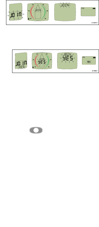
i.Pressanybuttononadisplaythathas‘JOIN’
ashingonscreen.
TheDisplaywillshow‘JOINYES’
ii.Conrmbypressinganybuttononthesame
display.
Thedisplaywillshow‘DONE’.
Ifconrmationisnotcompletedwithin25seconds,
‘FAIL’willbeshownwhichmeansthedisplayhas
notjoinedthenetwork.
Whenthecountdowniscomplete,thechosen
displayreturnstotheAutonetworkingpage.Press
andholdthe
Setupbuttonfor2secondsto
returntonormaloperation.
11.T estthesystem:
i.Switchoffthechosendisplay.
ii.Switchonthechosendisplay.
Ifsomeunitsdonotpowerup,checkthatallnew
unitsarewithin300mm(11.8in)ofthechosen
displayandifrequired,areconnectedtoapower
source.
12.Repeatthestepsaboveuntilallunitshavejoined
thenetwork.
13.Ifyouarereplacingolderunits,removethemfrom
thevessel.
14.Ensureallunitsareworkingcorrectlybefore
mountingthem.
ProductidenticationonMicronet
TheMicro-T alkgatewayisidentieddifferentlyduring
theAutonetworkingprocessthanwhencheckingthe
HealthpagesfromaMicronetdisplay.
DuringAutonetworkingthegatewayisidentiedasan
NMEA2000device(i.e.:2000,N2000,orN2000)
WhencheckingtheHealthpagesfromaMicronet
displaythegatewayisidentiedasType7device(i.e:
TYP7,TYPE7orTYPE7.
24

5.1Surfacemounting
Theunitcanbemountedonasurfacethatisupto
approximately28mm(1.10in)thickusingthexings
suppliedwiththeunit.T omountonathickersurface
longerstudswillberequired.
1.Ensuringcorrectorientation,afxthesupplied
mountingtemplatetothemountingsurfaceatthe
desiredlocation.
2.Drill3xxingholesand1xcableholeusingdrillbit
sizesasindicatedonthetemplate.
3.Placethewaterproofgasketintopositiononthe
undersideoftheunit.
4.ConnectthecabletoanavailableSeaTalkngspur
connectionthenconnecttheotherendtothe
connectorontheundersideoftheunitandsecure
usingthelockingcollar.
5.Screwthethreadedstudsintotheundersideofthe
unit(theseshouldbehand-tightonly).
6.Positiontheunitsothatthemountingstudspass
throughtheholesinthemountingsurface.
7.Securetheunittothemountingsurfaceusingthe
thumbnuts.(theseshouldbehand-tightonly).
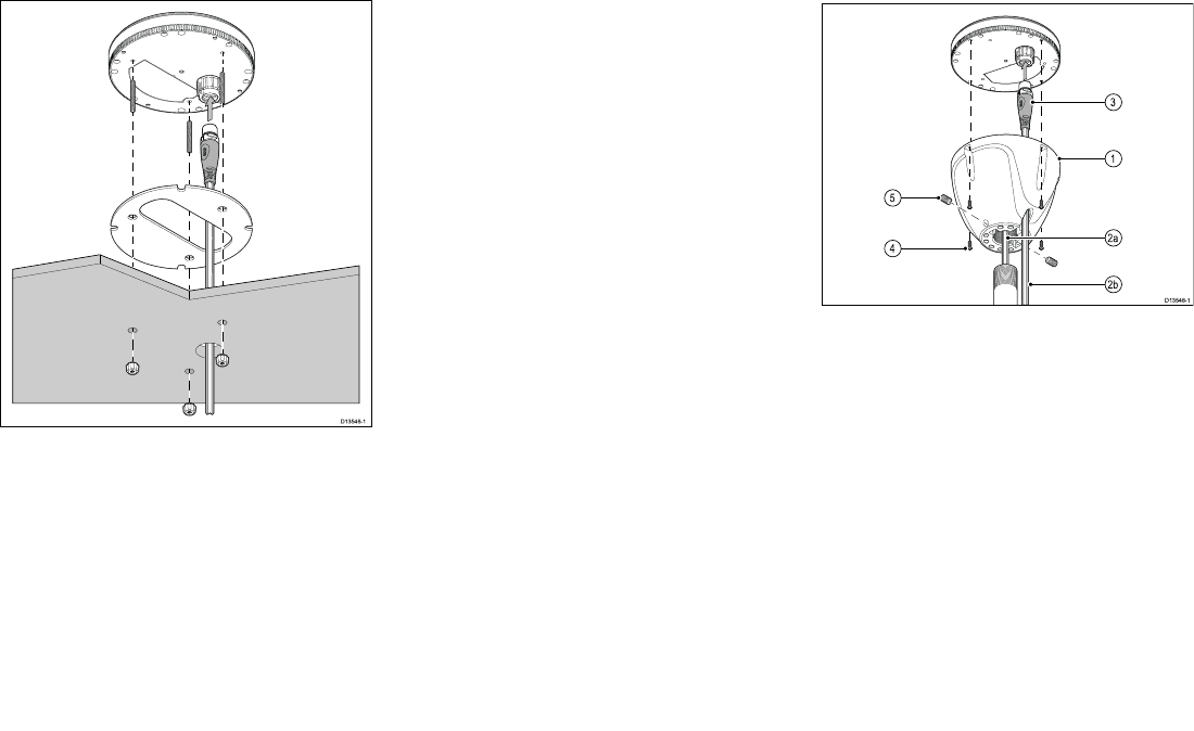
5.2Polemounting
ThePolemountkit(A80370)canbeusedtomount
yourproductonapoleorrail.
Polemountingrequiresapolewitha1inch14TPI
thread:
1.ScrewthePolemountadaptortothetopofthepole.
2.Feedthecablethrougheither:
•2a)thecenterofthePolemountadaptorand
pole,or
•2b)thecableexithole.
3.ConnectthecabletoanavailableSeaTalkngspur
connectionthenconnecttheotherendofthecable
totheconnectorontheundersideoftheunitand
secureusingthelockingcollar.
4.Ensuringcorrectorientation,Securetheunittothe
Polemountadaptorusingthexingssuppliedwith
theadaptor.
5.Fixtheunit’sorientationbytighteningthegrub
screws.
Thegrubscrewsandtheircaptivenutsaresupplied
ttedtotheadaptor.
26
Note:ThePoleMountAdaptormayalsobeusedto
railmounttheunitusinga3rdpartyrailclampwith
a1inch14TPIthread.
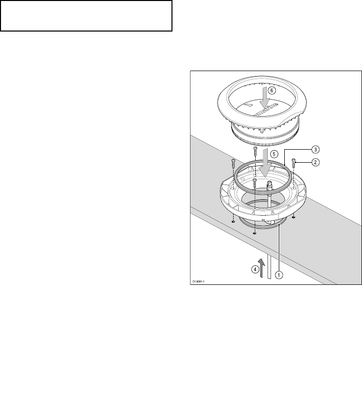
5.3Surfacemountingusing
theDeckmountingkit
TheDeckmountingkit(A80437)canbeusedtosurface
orbracketmountyourproduct.
TheRiserandBracketpiecesarenotrequiredforthis
installation.
1.UsetheMountingtraytemplatesuppliedwiththe
Deckmountingkittodrill4holesinthemounting
surface,plusa22mm(7/8in)holeforthe
SeaTalkng®cable.Placethesmallsealingringin
thegroovelocatedonthebottomofthemounting
tray.
2.Securethetraytothemountingsurfaceusingthe
suppliedxings.
3.Placethelargesealingringintothegrooveonthe
uppersideofthemountingtray.
4.PulltheSeaTalkng®cablethroughthemounting
surfaceholeandthemountingtray.Pluginthecable
connectorontheundersideoftheunitandsecure
byrotatingthelockingcollarclockwise2clicks.
5.SecuretheunittotheMountingtraybypositioning
theunitwiththeLEDfacingforwardandinserting
theunitintothegroovesintheMountingtray.
6.PlacetheMountingtrimovertheunitslightlyoffset,
andthentwisttheMountingtrimclockwiseuntilit
locksintoposition.
Installation27
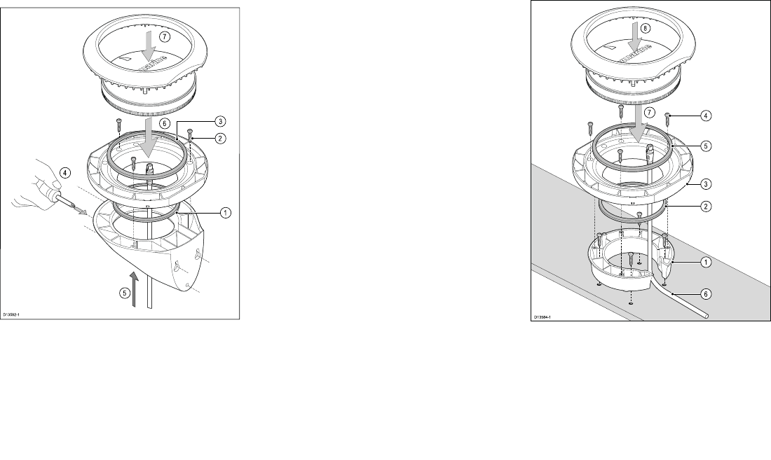
5.4Bracketmountingusing
theDeckmountingkit
TheDeckmountingkit(A80437)canbeusedtowall
mountyourproduct.
TheRiserpieceisnotrequiredforbracketmounting
theproduct.
1.Placethesmallsealingringinthegroovelocatedon
thebottomofthemountingtray.
2.Securethetraytothebracketusingthesupplied
xingsin3positions.
3.Placethelargesealingringintothegrooveonthe
uppersideofthemountingtray.
4.Securethebrackettothemountingsurfaceusing
thesuppliedmountingtemplate.Securethebracket
usingthesuppliedxingsin3positions.
5.PulltheSeaTalkng®cablethroughthemounting
bracketholeandthemountingtray.Pluginthecable
connectorontheundersideoftheunitandsecure
byrotatingthelockingcollarclockwise2clicks.
6.SecuretheunittotheMountingtraybypositioning
theunitwiththeLEDfacingforwardandinserting
theunitintothegroovesintheMountingtray.
7.PlacetheMountingtrimovertheunitslightlyoffset,
andthentwisttheMountingtrimclockwiseuntilit
locksintoposition.
5.5Surfacemountingusing
theRiser
TheDeckmountingkit(A80437)canbeusedtoraise
theproductfromthemountingsurface.
TheWallbracketisnotrequiredwhenusingtheRiser.
1.UsethesuppliedDeckmountrisertemplatetodrill4
holesinthemountingsurface.SecuretheRiserto
themountingsurfaceusing4xsuppliedxings.
2.Placethesmallsealingringinthegroovelocatedon
thebottomofthemountingtray.
3.PositiontheMountingtrayontopoftheRiser.
4.SecuretheMountingtraytotheRiserusing3x
suppliedxings.
28
5.Placethelargesealingringintothegrooveonthe
uppersideoftheMountingtray.
6.PulltheSeaT alkng®cablethroughtheRiserand
Mountingtray.Pluginthecableconnectoronthe
undersideoftheunitandsecurebyrotatingthe
lockingcollarclockwise2clicks.
7.SecuretheunittotheMountingtraybypositioning
theunitwiththeLEDfacingforwardandinserting
theunitintothegroovesintheMountingtray.
8.PlacetheMountingtrimovertheunitslightlyoffset,
andthentwisttheMountingtrimclockwiseuntilit
locksintoposition.
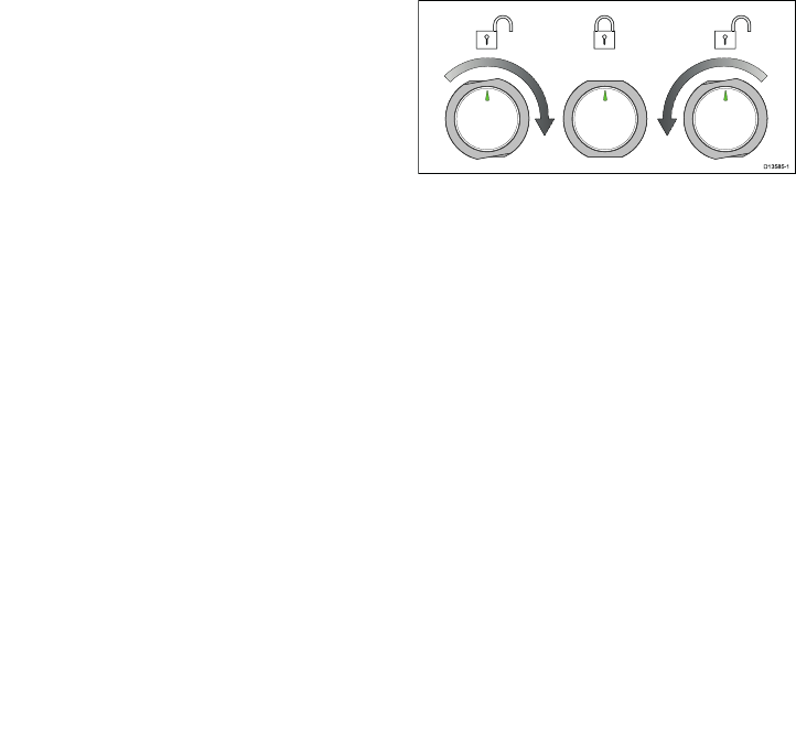
5.6Lockingandreleasingthe
unit
Followthestepsbelowtolockandreleasetheunitfrom
themountingadaptor.
1.T olocktheunit:PlacetheMountingtrimoverthe
unitslightlyoffset,andthentwisttheMountingtrim
clockwiseuntilitlocksintoposition.
2.T oreleasetheunit:Twistthetrimpiece
counter-clockwiseandthenliftawayfromtheunit.
Installation29

30


6.1Troubleshooting
Thetroubleshootinginformationprovidespossible
causesandcorrectiveactionrequiredforcommon
problemsassociatedwithmarineelectronics
installations.
AllRaymarineproductsare,priortopackingand
shipping,subjectedtocomprehensivetestandquality
assuranceprograms.However,ifyouexperience
problemswiththeoperationofyourproductthissection
willhelpyoutodiagnoseandcorrectproblemsinorder
torestorenormaloperation.
Ifafterreferringtothissectionyouarestillhaving
problemswithyourunit,pleasecontactRaymarine
TechnicalSupportforfurtheradvice.
32
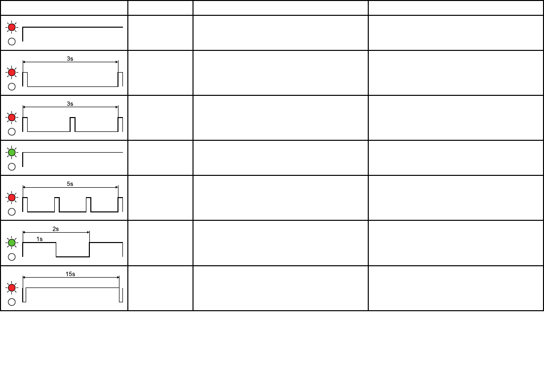
6.2LEDDiagnostics
LEDSequenceLEDColorStatusAction
RedSeaTalkng®poweringupNone
RedPowerupfailedPowercycleunit
RedMultipleMicro-T alkgatewaysdetectedonSeaTalkng®Removeallbut1Micro-TalkgatewayfromSeaT alkng®
GreenSeaTalkng®poweredup,MicronetpoweringupNone
RedMicronetconnectionfailedPowercycletheunit
GreenMicronetjoiningnetworkNone
RedMicronetsearchingfornetworkNone
Systemchecksandtroubleshooting33
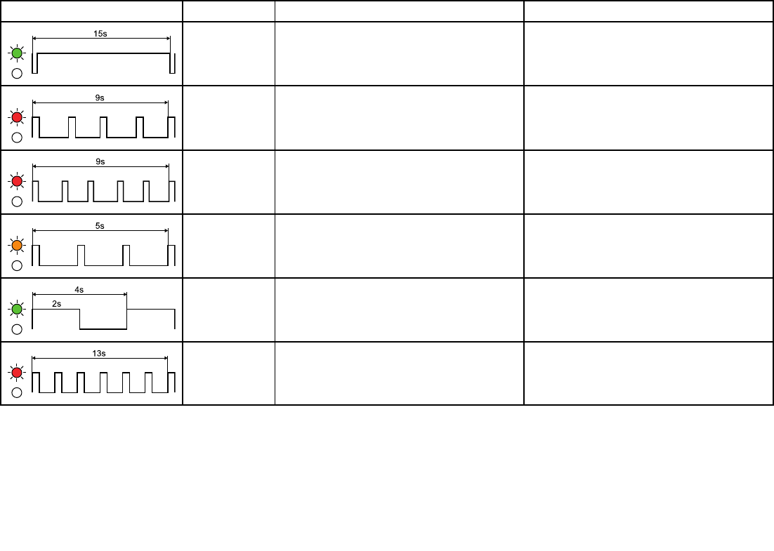
LEDSequenceLEDColorStatusAction
GreenNormaloperationNone
RedSeaTalkng®connectionlost,Micronetwillreverttosearching
modeafter30seconds
1.Powercycleunit
2.Checknetworkconnections
RedNodatabeingreceivedonSeaTalkng®,Micronetwillrevertto
searchingmodeafter30seconds
1.Powercycleunit
2.Checknetworkconnections
AmberDevicefailedtocommencesoftwareupdateprocess.Powercycleunitandretrytheupdate
GreenSoftwareupdateinprogressNone
RedSoftwareupdatefailedPowercycleunitandretrytheupdate
34


7.1Serviceandmaintenance
Thisproductcontainsnouserserviceablecomponents.
Pleasereferallmaintenanceandrepairtoauthorized
Raymarinedealers.Unauthorizedrepairmayaffect
yourwarranty.
7.2Routineequipmentchecks
Raymarinestronglyrecommendsthatyoucompletea
numberofroutinecheckstoensurethecorrectand
reliableoperationofyourequipment.
Completethefollowingchecksonaregularbasis:
•Examineallcablesforsignsofdamageorwearand
tear.
•Checkthatallcablesaresecurelyconnected.
7.3Productcleaning
Bestcleaningpractices.
Whencleaningproducts:
•Ifyourproductincludesadisplayscreen,doNOT
wipethescreenwithadrycloth,asthiscouldscratch
thescreencoating.
•DoNOTuseabrasive,oracidorammoniabased
products.
•DoNOTuseajetwash.
36


8.1Raymarineproduct
supportandservicing
Raymarineprovidesacomprehensiveproductsupport
service,aswellaswarranty,service,andrepairs.You
canaccesstheseservicesthroughtheRaymarine
website,telephone,ande-mail.
Productinformation
Ifyouneedtorequestserviceorsupport,pleasehave
thefollowinginformationtohand:
•Productname.
•Productidentity.
•Serialnumber.
•Softwareapplicationversion.
•Systemdiagrams.
Youcanobtainthisproductinformationusingthemenus
withinyourproduct.
Servicingandwarranty
Raymarineoffersdedicatedservicedepartmentsfor
warranty,service,andrepairs.
Don’tforgettovisittheRaymarinewebsiteto
registeryourproductforextendedwarrantybenets:
http://www.raymarine.co.uk/display/?id=788.
RegionTele-
phone
E-mail
United
Kingdom
(UK),EMEA,
andAsia
Pacic
+44
(0)1329
246932
emea.service@raymarine.com
UnitedStates
(US)
+1(603)
3247900
rm-usrepair@ir.com
Websupport
Pleasevisitthe“Support”areaoftheRaymarine
websitefor:
•ManualsandDocuments—http://www.rayma-
rine.com/manuals
•FAQ/Knowledgebase—http://www.rayma-
rine.com/knowledgebase
•Technicalsupportforum—http://forum.rayma-
rine.com
•Softwareupdates—http://www.raymarine.com/soft-
ware
Telephoneande-mailsupport
RegionTele-
phone
E-mail
UnitedKingdom
(UK),EMEA,
andAsiaPacic
+44
(0)1329
246777
support.uk@raymarine.com
UnitedStates
(US)
+1(603)
324
7900
(Toll-
free:
+800
539
5539)
support@raymarine.com
Australiaand
NewZealand
+612
8977
0300
aus.support@raymarine.com
(Raymarinesubsidiary)
France+33(0)1
464972
30
support.fr@raymarine.com
(Raymarinesubsidiary)
Germany+49
(0)40
237808
0
support.de@raymarine.com
(Raymarinesubsidiary)
Italy+3902
9945
1001
support.it@raymarine.com
(Raymarinesubsidiary)
RegionTele-
phone
E-mail
Spain+3496
2965
102
sat@azimut.es
(AuthorizedRaymarine
distributor)
Netherlands+31
(0)26
3614
905
support.nl@raymarine.com
(Raymarinesubsidiary)
Sweden+46
(0)317
633670
support.se@raymarine.com
(Raymarinesubsidiary)
Finland+358
(0)207
619937
support.@raymarine.com
(Raymarinesubsidiary)
Norway+47692
64600
support.no@raymarine.com
(Raymarinesubsidiary)
Denmark+45437
16464
support.dk@raymarine.com
(Raymarinesubsidiary)
Russia+7495
788
0508
info@mikstmarine.ru
(AuthorizedRaymarine
distributor)
Viewingproductinformation
WithyourMFDHomescreendisplayed:
1.SelectSet-up.
2.SelectMaintenance.
3.SelectDiagnostics.
4.SelectSelectDevice.
5.Selecttherelevantproductfromthelist.
TheDiagnosticspageisdisplayed.
38
8.2Learningresources
Raymarinehasproducedarangeoflearningresources
tohelpyougetthemostoutofyourproducts.
Videotutorials
Raymarineofcialchannelon
YouTube:
•http://www.youtube.com/u-
ser/RaymarineInc
VideoGallery:
•http://www.rayma-
rine.co.uk/view/?id=2679
ProductSupportvideos:
•http://www.rayma-
rine.co.uk/view/?id=4952
Note:
•Viewingthevideosrequiresadevicewithan
Internetconnection.
•SomevideosareonlyavailableinEnglish.
Trainingcourses
Raymarineregularlyrunsarangeofin-depthtraining
coursestohelpyoumakethemostofyourproducts.
VisittheTrainingsectionoftheRaymarinewebsitefor
moreinformation:
•http://www.raymarine.co.uk/view/?id=2372
FAQsandKnowledgeBase
RaymarinehasproducedanextensivesetofFAQsand
aKnowledgeBasetohelpyoundmoreinformation
andtroubleshootanyissues.
•http://www.raymarine.co.uk/knowledgebase/
Technicalsupportforum
YoucanusetheT echnicalsupportforumtoaska
technicalquestionaboutaRaymarineproductortond
outhowothercustomersareusingtheirRaymarine
equipment.Theresourceisregularlyupdatedwith
contributionsfromRaymarinecustomersandstaff:
•http://forum.raymarine.com
Technicalsupport39

40


9.1Technicalspecication
Nominalsupplyvoltage12Vdc(SuppliedbySeaTalkng®)
Operatingvoltagerange9Vdcto16Vdc(protectedupto
32Vdc)
Powerconsumption25mAatnominalsupplyvoltage
EnvironmentalInstallationenvironment
•Operatingtemperature:-20ºC
to+55ºC(-4ºFto131ºF)
•Storagetemperature:-30ºCto
+70ºC(-22ºFto158ºF)
•Relativehumidity:max93%
•WaterprooftoIPx6andIPx7
Supportedconnection
protocols
•SeaT alkng®/NMEA2000(via
DeviceNetadaptor)
•Micronet(wireless)
LEN(refertoSeaTalkng®
Referencemanualfor
moreinformation)
1
42


10.1Accessories
Thefollowingaccessoriesareavailable:
Accessories
ItemPartnumber
Pole/railmountingadaptorkitA80370
6mSeaTalkngwhitespur
cable
A06072
Deckmounting
(Clamshell/Riser)kit
A80437
10.2SeaTalkng®cabling
components
SeaTalkngcablingcomponentsandtheirpurposes.
Connection/CableNotes
Backbonecable(various
lengths)
Themaincablecarryingdata.
Spursfromthebackboneare
usedtoconnectSeaTalkng
devices.
T-piececonnectorUsedtomakejunctionsinthe
backbonetowhichdevices
canthenbeconnected.
TerminatorRequiredateitherendofthe
backbone.
InlineterminatorUsedtoconnectaspur
cabledirectlytotheendofa
backbone;usefulforlonger
cableruns.
SpurcableUsedtoconnectdevices
tothebackbone.Devices
maybedaisychainedor
connecteddirectlytothe
T-pieces.
SeaTalkng5–wayconnectorUsedtobranch,split,or
makeadditionalconnections
inSeaTalkorSeaT alkng
networks.
BlankingplugInsertedintounusedspur
connectorpositionsina
5-wayconnectororT-piece.
10.3SeaTalkng®cablesand
accessories
SeaTalkngcablesandaccessoriesforusewith
compatibleproducts.
DescriptionPartNoNotes
SeaTalkngstarterkitT70134Includes:
•1x5Wayconnector
(A06064)
•2xBackboneterminator
(A06031)
•1x3m(9.8ft)spur
cable(A06040)
•1xPowercable
(A06049)
SeaTalkng
BackboneKit
A25062Includes:
•2x5m(16.4ft)
Backbonecable
(A06036)
•1x20m(65.6ft)
Backbonecable
(A06037)
•4xT-piece(A06028)
•2xBackboneterminator
(A06031)
•1xPowercable
(A06049)
SeaTalkng0.4m
(1.3ft)spur
A06038
SeaTalkng1m
(3.3ft)spur
A06039
SeaTalkng3m
(9.8ft)spur
A06040
44

DescriptionPartNoNotes
SeaTalkng5m
(16.4ft)spur
A06041
SeaTalkng0.4m
(1.3ft)elbowspur
A06042
SeaTalkng0.4m
(1.3ft)backbone
A06033
SeaTalkng1m
(3.3ft)backbone
A06034
SeaTalkng3m
(9.8ft)backbone
A06035
SeaTalkng5m
(16.4ft)backbone
A06036
SeaTalkng9m
(29.5ft)backbone
A06068
SeaTalkng20m
(65.6ft)backbone
A06037
SeaTalkngtobare
ends1m(3.3ft)
spur
A06043
SeaTalkngtobare
ends3m(9.8ft)
spur
A06044
SeaTalkngPower
cable
A06049
SeaTalkng
Terminator
A06031
SeaTalkngT-pieceA06028Provides1xspur
connection
SeaTalkng5–way
connector
A06064Provides3xspur
connections
DescriptionPartNoNotes
SeaTalkng
backboneextender
A06030
SeaTalkto
SeaTalkng
converterkit
E22158Allowstheconnection
ofSeaTalkdevicestoa
SeaTalkngsystem.
SeaTalkngInline
terminator
A80001Providesdirectconnection
ofaspurcabletotheend
ofabackbonecable.No
T-piecerequired.
SeaTalkngBlanking
plug
A06032
ACU/SPX
SeaTalkngspur
cable0.3m(1.0ft)
R12112ConnectsanSPXcourse
computeroranACUtoa
SeaTalkngbackbone.
SeaTalk(3pin)to
SeaTalkngadaptor
cable0.4m(1.3ft)
A06047
SeaTalkto
SeaTalkngspur1
m(3.3ft)spur
A22164
SeaTalk2(5pin)to
SeaTalkngadaptor
cable0.4m(1.3ft)
A06048
DeviceNetadaptor
cable(Female)
A06045Allowstheconnectionof
NMEA2000devicestoa
SeaTalkngsystem.
DeviceNetadaptor
cable(Male)
A06046Allowstheconnectionof
NMEA2000devicestoa
SeaTalkngsystem.
DescriptionPartNoNotes
DeviceNetadaptor
cable(Female)to
bareends.
E05026Allowstheconnectionof
NMEA2000devicestoa
SeaTalkngsystem.
DeviceNetadaptor
cable(Male)to
bareends.
E05027Allowstheconnectionof
NMEA2000devicestoa
SeaTalkngsystem.
Sparesandaccessories45

46

AppendixANMEA2000PGN
support
TheunitsupportsthefollowingNMEA2000PGNs.
PGNDescription
Receive
(Rx)
Transmit
(Tx)
5990
4
ISORequest●
5993
2
ISO
Acknowledgement●
6016
0
ISOTransport
protocol,data
transfer
●
6041
6
ISOTransport
protocol,connection
management
●●
6092
8
ISOAddressclaim●●
6524
0
ISOCommanded
address●
1262
08
NMEA-Request
groupfunction●
1262
08
NMEA-Command
groupfunction●
1262
08
NMEA-
Acknowledgegroup
function
●
1264
64
TransmissionPGN
list●
1264
64
ReceivedPGNlist●
1269
92
Systemtime●●
PGNDescription
Receive
(Rx)
Transmit
(Tx)
1269
93
Heartbeat●
1269
96
Productinformation●
1269
98
Conguration
information●
1272
37
Heading/track
control●●
1272
50
Vesselheading●●
1272
58
Magneticvariation●●
1282
59
Speed,water
referenced●●
1282
67
Waterdepth●●
1282
75
Distancelog●●
1290
25
Position,rapid
update●
1290
26
COG&SOGrapid
update●●
1290
29
GNSSpositiondata●●
1290
33
Localtimeoffset
(formerlyTimeand
date)
●●
1292
83
Crosstrackerror●●
PGNDescription
Receive
(Rx)
Transmit
(Tx)
1282
84
Navigationdata●●
1292
85
NavigationRoute/
WPinformation●●
1300
67
RouteandWP
service–Route–
WPname&position
●
1300
68
RouteandWP
service–Route–
WPname
●
1300
74
RouteandWP
service–WPlist–
WPname&position
●
1303
06
Winddata●●
1303
10
Environmental
parameters●●
1303
16
Temperature,
extendedrange●●
1305
77
Directiondata●
NMEA2000PGNsupport47

48

Index
A
Accessories.....................................................................44
Autonetworking.............................................................22–23
B
Backbonelength............................................................19–20
Batteryconnection..............................................................20
Boxcontents,SeePartssupplied
Bracketmounting...............................................................28
C
Cablebendradius...............................................................18
Cableconnection,SeeConnectingcables
Cableconnector,SeeConnectingcables
Cableprotection.................................................................18
Cablerouting....................................................................18
Cleaning......................................................................7,36
Compasssafedistance.........................................................16
Compatibledisplays.............................................................22
Connectingcables..............................................................19
Connections.....................................................................18
Connectors,SeeConnections
Contacts........................................................................38
D
Damping........................................................................11
Databridging....................................................................10
DataDamping,SeeDamping
Datadifferences.................................................................11
Datasource,SeeMultipledatasources
Deckmountingkit...........................................................27–29
Diagnostics.....................................................................33
Distributionpanelconnection....................................................20
Doubledamping.................................................................11
E
ElectromagneticCompatibility...................................................16
EMC,SeeElectromagneticCompatibility
Environmentalparameters......................................................42
F
Frequency,SeeOperatingfrequency
Fuserating......................................................................19
I
Installation..................................................................26–29
Installationequipment,SeeTools
Interference.....................................................................16
SeealsoCompasssafedistance
L
LEDstatus......................................................................33
LEN,SeeLoadequivalencynumber,SeeLoadEquivalencyNumber
Loadequivalencynumber.......................................................19
Locationrequirements..........................................................15
Lockingcollar...................................................................19
M
Maintenance..................................................................7,36
Maximumrange,SeeRange
Maximumsystemloading.......................................................20
MDS,SeeMultipledatasources
Micro-Talk.......................................................................10
Micronet.........................................................................11
Micronetdisplays...............................................................22
Mountinglocation,SeeLocationrequirements
Mountingtemplate..............................................................10
Multipledatasources...........................................................11
N
Networkexamples..............................................................21
Networklength,SeeBackbonelength
Sparesandaccessories51

Networking......................................................................11
SeealsoAutonetworking
NMEA2000.....................................................................47
Nominalsupplyvoltage.........................................................42
O
Operatingfrequency............................................................11
Operatinglicense...............................................................11
Operatingvoltagerange........................................................42
Optimumperformance..........................................................15
Orientation......................................................................15
P
Packcontents,SeePartssupplied
Partssupplied...................................................................14
PGNs...........................................................................47
Polemounting...................................................................26
Powerconnectionpoint.........................................................19
Powerconsumption.............................................................42
Powersupply,SeeSeaT alkngpowersupply
Productdimensions,SeeDimensions
Productfeatures................................................................10
Productloading,SeeLoadEquivalencyNumber
Productorientation,SeeOrientation
Productsupport.................................................................38
R
Railmounting...................................................................26
Range...........................................................................15
Riser............................................................................28
Routinechecks..................................................................36
S
SeaTalkng.......................................................................11
Securingcables.................................................................18
ServiceCenter..................................................................38
Servicing......................................................................7,36
Softwareupdates...............................................................14
Strainrelief,SeeCableprotection
Surfacemounting...........................................................26–28
Systemexamples,SeeNetworkexamples
T
Technicalsupport...............................................................38
Thermalbreakerrating..........................................................19
Tools............................................................................15
Troubleshooting.................................................................32
Typicalsystems,SeeNetworkexamples
U
Upgrading,SeeSoftwareupdates
W
WallBracket....................................................................28
Warranty........................................................................38
Wirelessinterface...............................................................11
52
Owner notes:
Owner notes:
Raymarine UK Limited, Marine House, Cartwright Drive, Fareham, PO15 5RJ. United Kingdom.
Tel: +44 (0)1329 246 700
www.raymarine.com