Flir BelgiumBA MTX2-8P Leisure Marine Radar User Manual
Raymarine UK Ltd. Leisure Marine Radar
UserManual.wiki
>
Flir BelgiumBA
>
MTX2 8P User Manual
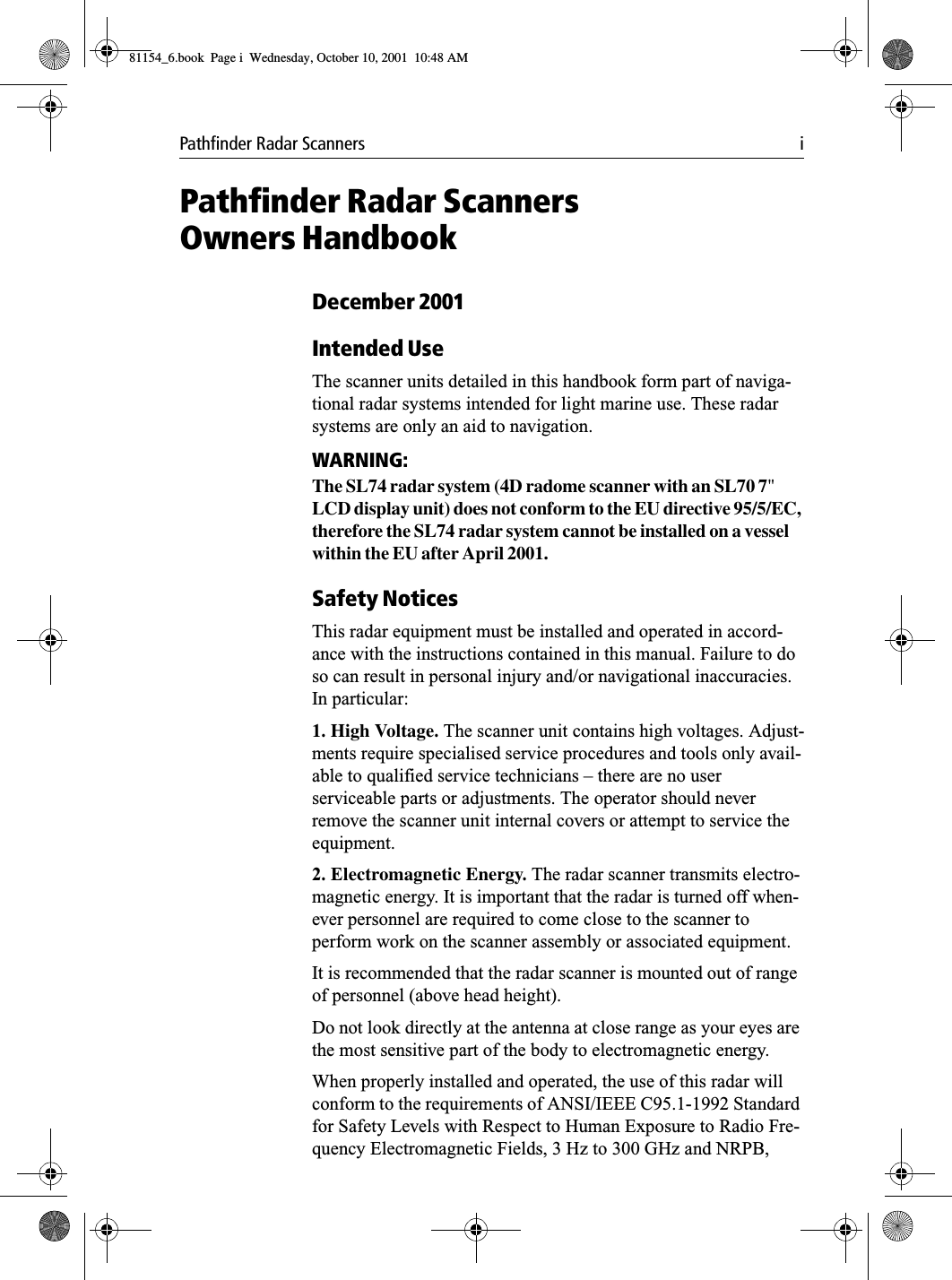
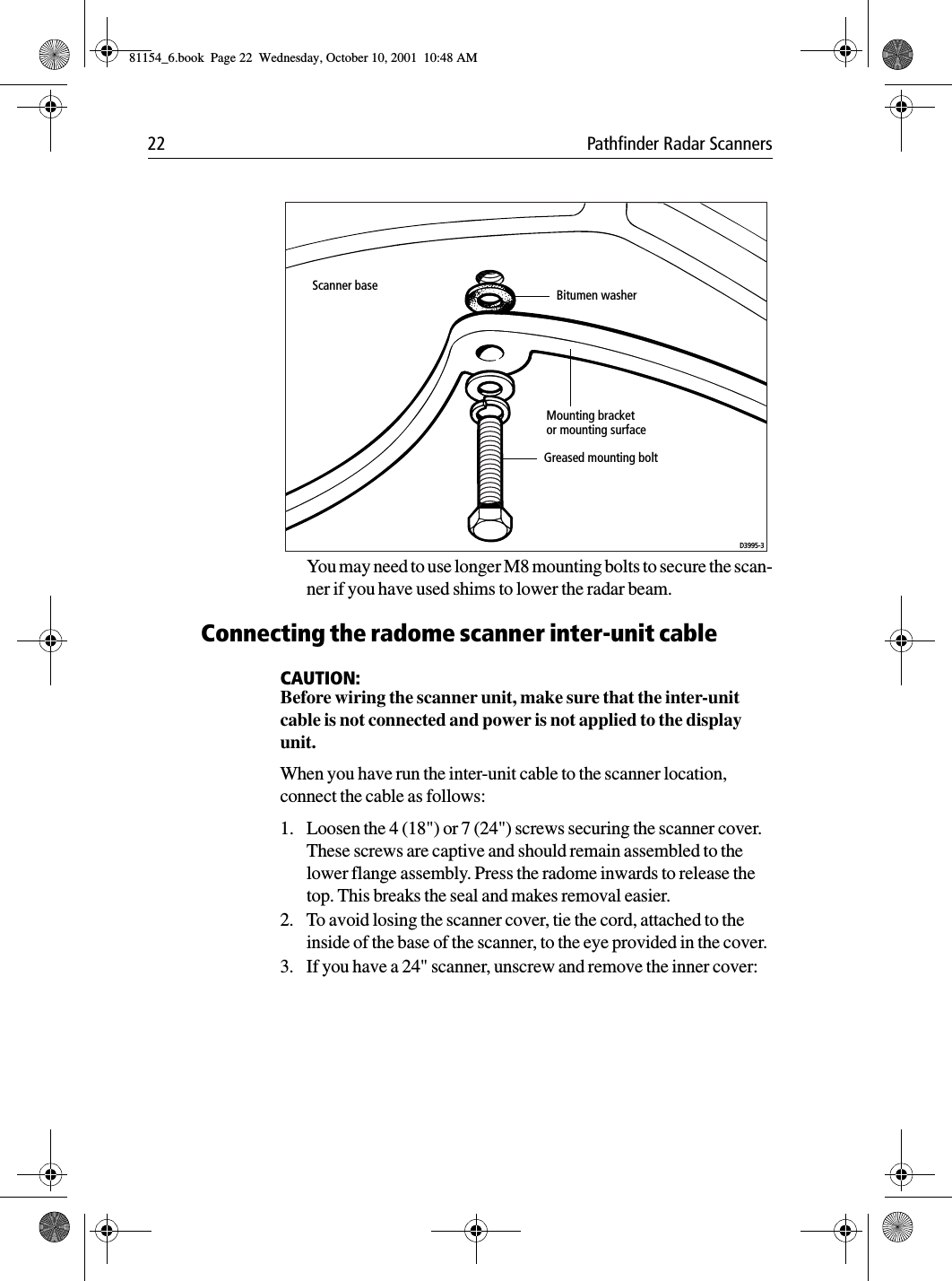
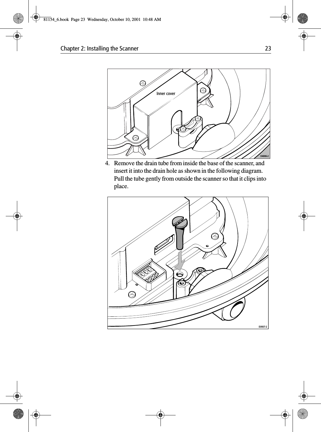
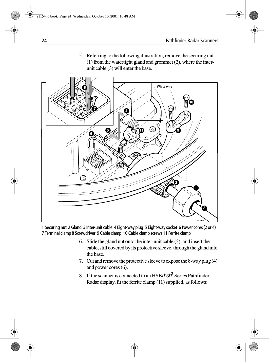
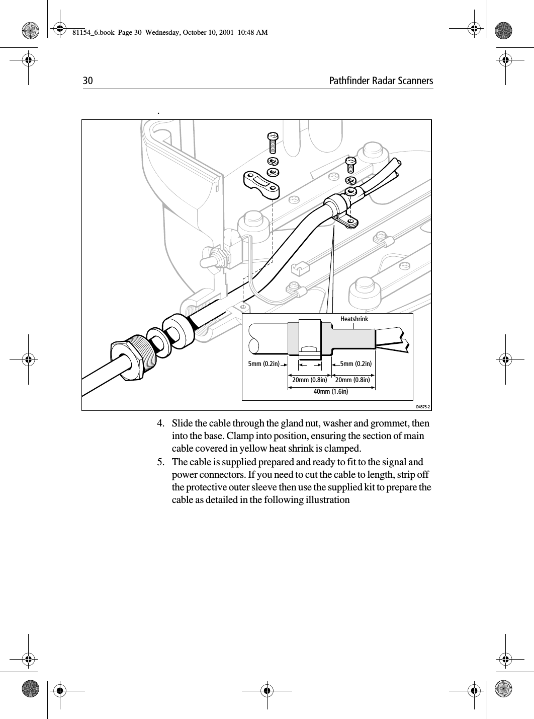
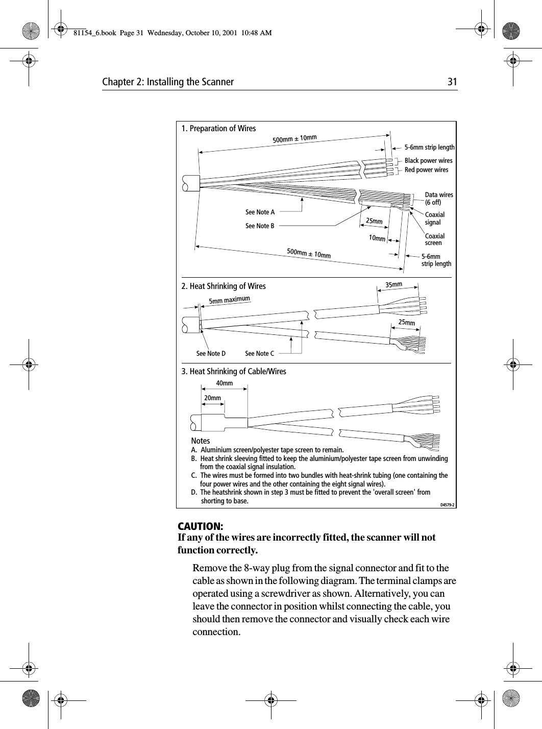
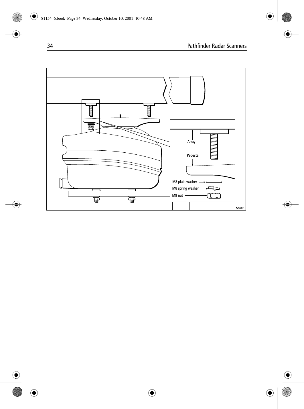
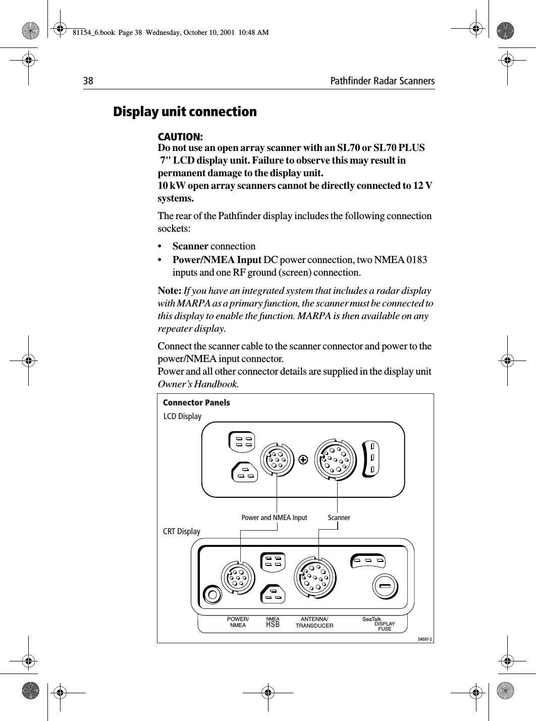
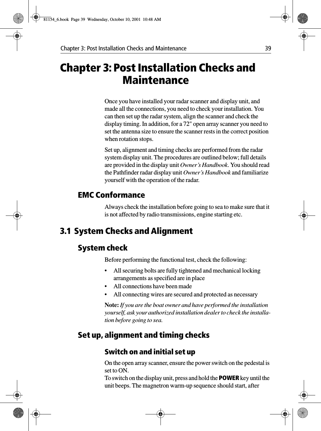
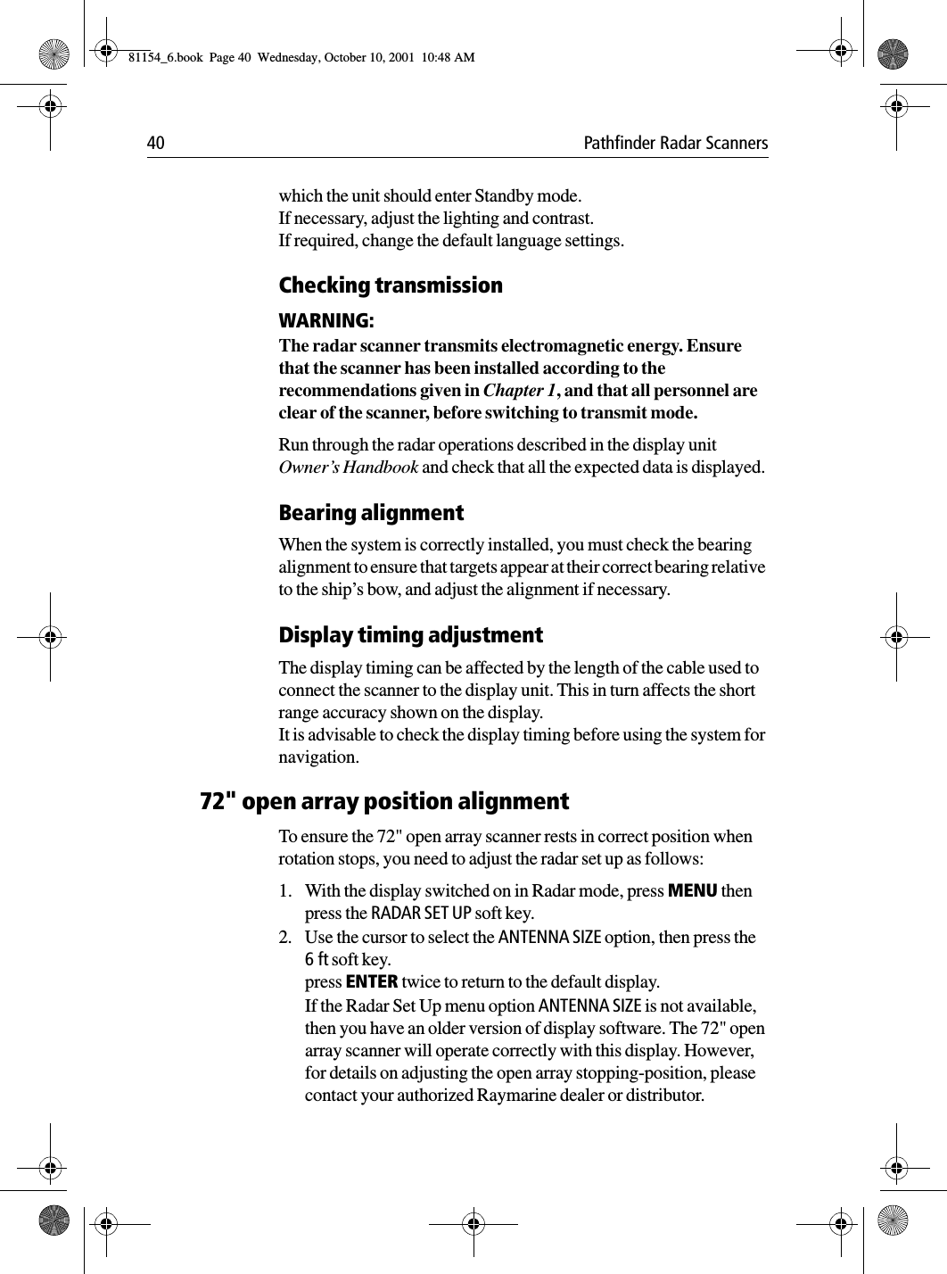
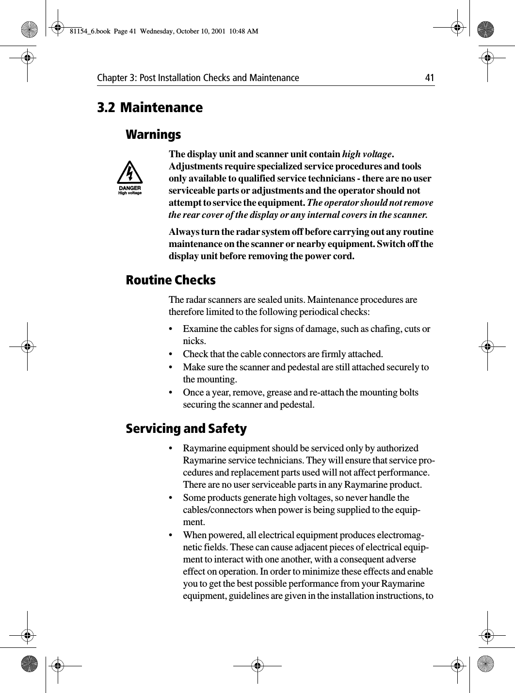
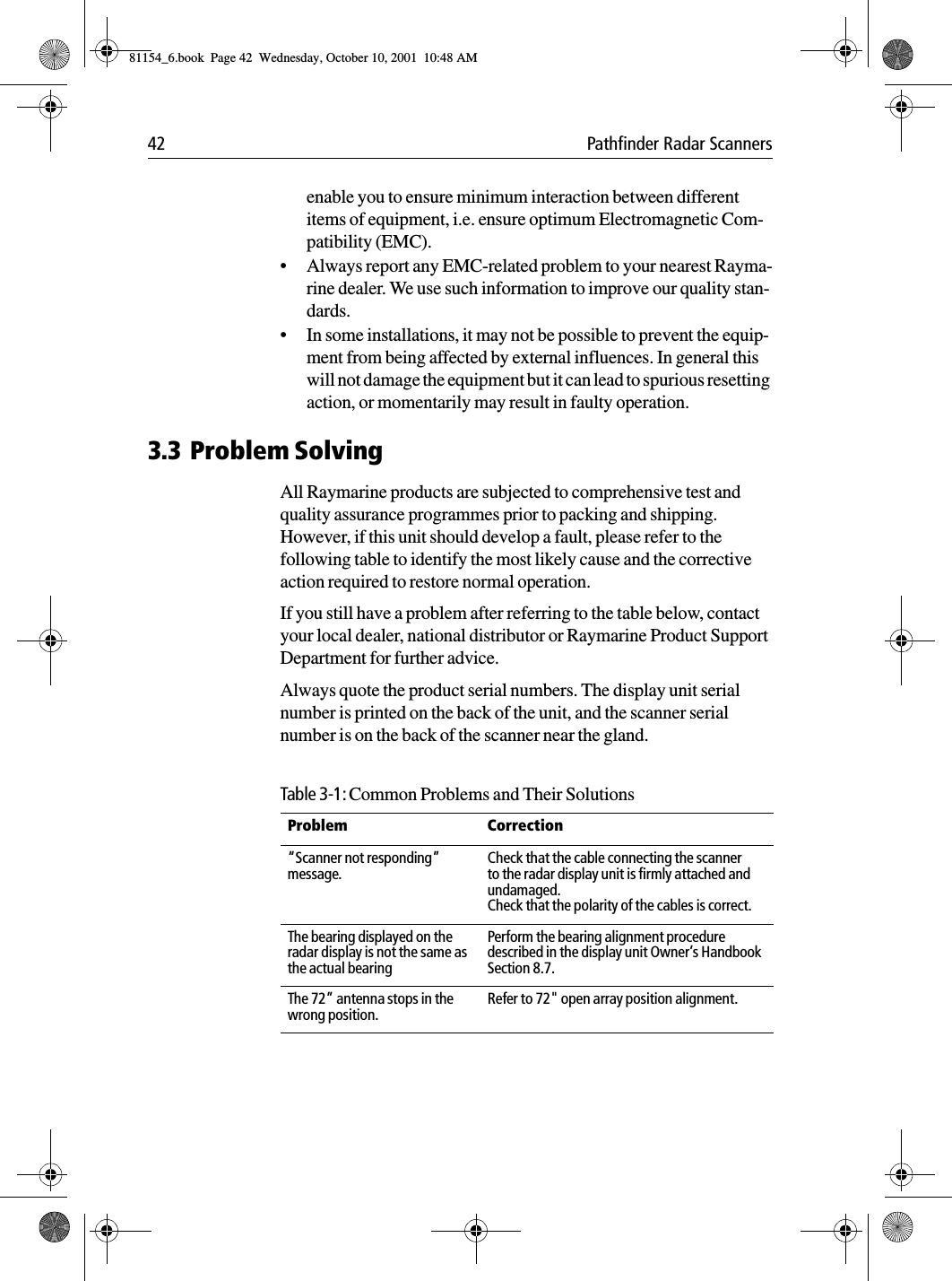
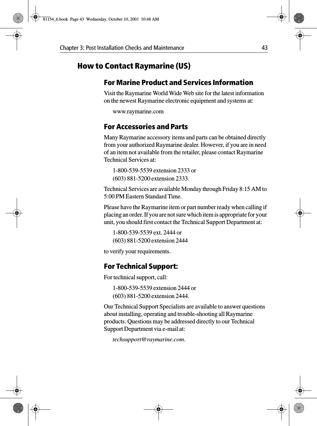
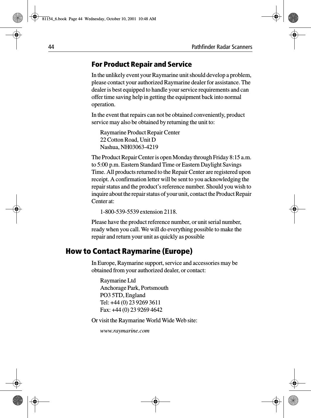
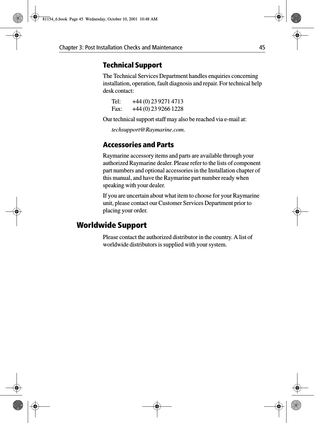
Owners handbook
Navigation menu
Upload a User Manual
Namespaces
Wiki Guide
HTML
PDF
Info
Views
User Manual
Discussion / Help
Navigation