Flir BelgiumBA RAY230 VHF Marine Transmitter User Manual RAY230 COVER
Raymarine UK Ltd. VHF Marine Transmitter RAY230 COVER
users manual
RAY230 & RAY230E
Fixed Mount
VHF Radio
Owner’s
Handbook
Document number: R49006_1
Date: May 2001

iii
PURPOSEPURPOSE
PURPOSEPURPOSE
PURPOSE
This handbook contains very important information on the installation,
operation, and maintenance of your RAY230 US version or RAY230E
European version VHF radio. To get the best results in operation and
performance, please take the time to read this handbook thoroughly.
RAY230 US VersionRAY230 US Version
RAY230 US VersionRAY230 US Version
RAY230 US Version
Raymarine radios comply with the Federal Communications Commission
(FCC) and Industry Canada requirements that regulate marine VHF radio
usage for the US and Canada, respectively.
Marine VHF radio users in the US must comply with all applicable FCC
rules and regulations, some of which are described here and in Section 7.
This information was current at the time this handbook was printed. Up-
to-date information, including licensing requirements, can be obtained on
the FCC website at:
www.fcc.gov/wtb/marine
FCC NOTICEFCC NOTICE
FCC NOTICEFCC NOTICE
FCC NOTICE
This device complies with PART 15 of the FCC Rules. Operation is subject
to the conditions that this device does not cause harmful interference.
Changes or modifications to this equipment not expressly approved in
writing by Raymarine, Incorporated could violate compliance with FCC
rules and void the operator’s authority to operate the equipment.
Station LicenseStation License
Station LicenseStation License
Station License
An FCC Ship Radio Station License and Call Sign are not required for most
recreational vessels travelling in US waters. However, you must obtain a
license if: (1) you are required by law or treaty to carry a radio on your
vessel; (2) your vessel travels to foreign ports; (3) you use marine radio
equipment on board your vessel other than marine VHF radios, any type
of Emergency Position Indicating Radio Beacon (EPIRB), any type of radar,
GPS or LORAN receivers, depth finders, CB radio, or amateur radio (an
amateur license is required). Ships that use MF/HF single side-band radio,
satellite communications, or telegraphy must continue to be licensed by
the FCC. You can obtain a Station License by completing FCC Form 605
and mailing it with the required fee to:
Federal Communications Commission
1270 Fairfield Road
Gettysburg, PA 17325-7245

iv
Operator LicenseOperator License
Operator LicenseOperator License
Operator License
An Operator License is not required to operate a VHF Marine Radio within
US territorial waters. However, a license is required to operate the radio if
you dock in a foreign port (including Canada and Mexico) or leave a foreign
port to dock in a U.S. port. You can request a Restricted Radiotelephone
Operator Permit from the FCC by filing Form 753.
Maritime Mobile Service Identity (MMSI)Maritime Mobile Service Identity (MMSI)
Maritime Mobile Service Identity (MMSI)Maritime Mobile Service Identity (MMSI)
Maritime Mobile Service Identity (MMSI)
A nine-digit Maritime Mobile Service Identity (MMSI) number is required
to operate the DSC equipment in this radio. You can request an MMSI
number from the FCC when you apply for a Station License. If your vessel
does not require a license, you may obtain an MMSI by contacting either
BoatUS (www.boatus.com) or MariTEL (www.maritelusa.com).
Once obtained, you can program the MMSI number into your RAY230
using the Menu Operation described in this handbook.
INDUSTRY CANADAINDUSTRY CANADA
INDUSTRY CANADAINDUSTRY CANADA
INDUSTRY CANADA
You do not need a license to operate this radio within sovereign waters of
Canada or the US. You will need a license to operate this radio outside of
Canada or the US. To obtain Industry Canada licensing information, contact
the nearest field or regional office, or write:
Industry Canada
Radio Regulatory Branch
Attention: DOSP
300 Slater Street
Ottawa, Ontario
Canada, KIA OC8
The following information about the radio is required to complete the
license application:
Industry Canada Type Approval ________
FCC Type Number PJ5RAY230
FCC Type Accepted Part 80
Output Power 1 watt (low) & 25 watts (high)
Modulation 16FE (FM)
Frequency Range 156.025-157.425

v
RAY230E European VersionRAY230E European Version
RAY230E European VersionRAY230E European Version
RAY230E European Version
The RAY230E is a VHF radiotelephone that includes equipment for Class
“D” Digital Selective Calling. It is intended for general communication
within the Maritime Mobile Service worldwide and is for use on non-
SOLAS vessels.
Compliance InformationCompliance Information
Compliance InformationCompliance Information
Compliance Information
The Declaration of Conformity to EC standards for radio equipment appears
on page vii.
LicenseLicense
LicenseLicense
License
Regulations in some regions require that you obtain an operator license
before operating VHF radio equipment. It is your responsibility to determine
whether a license is required in your area before operating this equipment.
Maritime Mobile Service Identity (MMSI)Maritime Mobile Service Identity (MMSI)
Maritime Mobile Service Identity (MMSI)Maritime Mobile Service Identity (MMSI)
Maritime Mobile Service Identity (MMSI)
An MMSI number is required to operate the Digital Selective Calling (DSC)
equipment in this radio. In some areas, a radio operator license is required
before an MMSI number will be issued. You can request an MMSI number
from the same agency that issues radio operator licenses in your area. You
can then program the MMSI number into your RAY230E using the Menu
Operation described in this handbook. If your region does not permit you
to program the MMSI number yourself, your distributor can program the
number for you.
Automatic Transmission Identification System (ATIS)Automatic Transmission Identification System (ATIS)
Automatic Transmission Identification System (ATIS)Automatic Transmission Identification System (ATIS)
Automatic Transmission Identification System (ATIS)
Your RAY230E can activate the ATIS feature, if needed. You can request
an ATIS number from the same agency that issues radio operator licenses
in your area. You can then program the ATIS number into your RAY230E
using the Menu Operation described in this handbook. If your region
does not permit you to program the ATIS number yourself, you can have
your distributor program the number for you. You must only enable this
feature when operating the radio in the inland waterways of European
countries that require automatic identification transmission.
SAFETY NOTICESAFETY NOTICE
SAFETY NOTICESAFETY NOTICE
SAFETY NOTICE
This device is only an aid to navigation. Its accuracy can be affected by
many factors including equipment failure or defects, environmental
conditions, and improper handling or use. It is the user's responsibility to
exercise common prudence and navigational judgement, and this device
should not be relied upon as a substitute for such prudence and judgement.

vi
Your Raymarine VHF radio generates and radiates radio frequency (RF)
electromagnetic energy (EME). This equipment must be installed and
operated in accordance with the instructions contained in this handbook.
Failure to do so can result in personal injury and/or product malfunction.
Antenna Mounting and EME ExposureAntenna Mounting and EME Exposure
Antenna Mounting and EME ExposureAntenna Mounting and EME Exposure
Antenna Mounting and EME Exposure
For optimal radio performance and minimal human exposure to radio
frequency electromagnetic energy, make sure the antenna is:
• connected to the radio before transmitting
• properly mounted
• located where it will be away from people
• located at least three feet (91 cm) from the Base Station transceiver
and Handsets
Adjustments or RepairAdjustments or Repair
Adjustments or RepairAdjustments or Repair
Adjustments or Repair
Adjustments require specialized service procedures and tools only available
to qualified service technicians – there are no user serviceable parts or
adjustments. The operator should never remove the cover or attempt to
service the equipment.
Raymarine products are supported by a network of Authorized Service
Representatives. For product information you may contact the following
regional centers:
UNITED STATES Raymarine, Incorporated
22 Cotton Road, Unit D
Nashua, NH 03063-4219
Telephone: 603-881-5200
800-539-5539
Fax: 603-864-4756
EUROPE Raymarine Limited
Anchorage Park
Portsmouth, Hampshire
England PO3 5TD
Telephone: +44 (0) 23 9269 3611
Fax: +44 (0) 23 9269 4642
© Raymarine, Inc. 2001

vii
[Declaration of Conformity goes here]

viii
GLOSSARY OF TERMSGLOSSARY OF TERMS
GLOSSARY OF TERMSGLOSSARY OF TERMS
GLOSSARY OF TERMS
All Scan ........................... Scans all channels
ATIS ................................ Automatic Transmission Identification
System; used for inland waterways in some
European countries
Canadian Channels ......... Channel designator as defined by the DOC
Carrier Wave ................... A Radio Frequency on which intelligence is
superimposed.
DSC ................................. Digital Selective Calling
Dual Watch ..................... Monitor channel 16 while working on another
channel
Duplex ............................. Transmit and receive on different frequencies
ETSI ................................ European Telecommunications Standards
Institute
FM .................................. Frequency Modulation
International Channels .... Channel designator as defined by the ITU
ITU .................................. International Telecommunications Union
LCD ................................. Liquid Crystal Display
Memory Scan .................. Scans only user selected memory channels
MMSI .............................. Maritime Mobile Service Identity; a number
issued by each country to identify maritime
stations.
NOAA ............................. National Oceanographic and Atmospheric
Administration
PLL .................................. Phase Locked Loop (a type of frequency
synthesizer)
PTT switch ...................... Microphone push-to-talk switch
RF .................................... Radio Frequency
RTCM .............................. Radio Technical Commission for Maritime
Services
RX ................................... Receiver
Simplex ............................ Transmit and receive on the same frequency
Squelch ........................... To suppress totally
TX ................................... Transmit
US Channels ................... Channel designations as defined by the FCC
VCO ................................. Voltage Controlled Oscillator
VHF ................................. Very High Frequency 30MHz to 300MHz
Weather Channels ........... Channels for routine and emergency weather
information broadcast by NOAA

ix
TABLE OF CONTENTS TABLE OF CONTENTS
TABLE OF CONTENTS TABLE OF CONTENTS
TABLE OF CONTENTS
SECTION 1 GENERAL DESCRIPTIONSECTION 1 GENERAL DESCRIPTION
SECTION 1 GENERAL DESCRIPTIONSECTION 1 GENERAL DESCRIPTION
SECTION 1 GENERAL DESCRIPTION
1.1 Introduction............................................................................. 1-1
1.2 Equipment Features ................................................................. 1-1
SECTION 2 INSTALLATIONSECTION 2 INSTALLATION
SECTION 2 INSTALLATIONSECTION 2 INSTALLATION
SECTION 2 INSTALLATION
2.1 Unpacking and Inspection ...................................................... 2-1
2.2 Equipment Supplied................................................................. 2-1
2.2.1 Optional Accessories .................................................. 2-1
2.3 Planning the Installation .......................................................... 2-2
2.4 Electrical Connections ............................................................. 2-4
2.4.1 DC Power and Hailer/NMEA Cable Connections ........ 2-4
2.4.2 Hailer Cable Connections ............................................ 2-5
2.4.3 NMEA Data ................................................................. 2-6
2.4.4 Using the SeaTalk Auxiliary Junction Box ................... 2-6
2.4.5 Antenna Connections ................................................. 2-7
2.4.6 Antenna Mounting Suggestions ................................ 2-8
2.4.7 Grounding ................................................................... 2-8
SECTION 3 OPERATIONSSECTION 3 OPERATIONS
SECTION 3 OPERATIONSSECTION 3 OPERATIONS
SECTION 3 OPERATIONS
3.1 Introduction............................................................................. 3-1
3.2 Control and LCD Display ........................................................ 3-1
3.2.1 Controls ...................................................................... 3-2
3.2.2 LCD Display ................................................................ 3-6
3.3 Radio Functions ...................................................................... 3-8
3.3.1 RAY230 US Version ..................................................... 3-8
3.3.2 RAY230E European Version ........................................ 3-9
3.4 Equipment Connections ........................................................ 3-12
3.5 Operating Procedures ............................................................ 3-13
3.5.1 Turning ON/OFF the power supply .......................... 3-13
3.5.2 Setting the Volume .................................................... 3-14
3.5.3 Setting the Squelch ................................................... 3-14
3.5.4 Using the Function Key ............................................ 3-14
3.5.5 Setting the Frequency Mode (RAY230) .................... 3-15
3.5.6 Setting the Frequency Mode (RAY230E) .................. 3-16
3.5.7 Receiving the Weather Channels .............................. 3-16
3.5.8 Selecting the Channel ............................................... 3-17
3.5.9 Selecting the Private Channel (RAY230E only) ......... 3-17
3.5.10 Priority Channel (RAY230) ........................................ 3-18
3.5.11 Priority Channel (RAY230E) ...................................... 3-18

x
3.5.12 Multi-Call Operation (RAY230E only) ....................... 3-18
3.5.13 Channel Memory ....................................................... 3-19
3.5.14 Setting the Transmission Power Output ................... 3-20
3.5.15 Reduced Reception Sensitivity (Local Mode) .......... 3-20
3.5.16 LCD Backlight Function ............................................ 3-20
3.5.17 Hailer Mode .............................................................. 3-21
3.5.18 Fog Alert/Siren Mode ............................................... 3-21
3.5.19 Cellular Phone Mode................................................. 3-22
3.5.20 Intercom Mode.......................................................... 3-23
3.5.21 Scan Mode ................................................................ 3-24
3.5.22 Monitor Mode .......................................................... 3-26
3.5.23 Priority using Multiple Handsets .............................. 3-27
3.5.24 NMEA Operation ...................................................... 3-30
3.5.25 Sea Talk Operation .................................................... 3-31
3.5.26 Digital Selective Calling (DSC) .................................. 3-31
3.5.26.1 Individual Call to Ship ....................................... 3-31
3.5.26.2 Individual Call to Shore Station ........................ 3-34
3.5.26.3 Receiving an Individual Call.............................. 3-36
3.5.26.4 Receiving a Group Call ...................................... 3-37
3.5.26.5 Transmitting an All Ships Call ........................... 3-38
3.5.26.6 Receiving an All Ships Call ............................... 3-39
3.5.26.7 Transmitting a Distress Call .............................. 3-40
3.5.26.8 Receiving a Distress Call ................................... 3-44
3.5.27 ATIS Operation (RAY230E only) ............................... 3-45
3.5.28 Alert Operation ......................................................... 3-45
3.5.30 Menu Operation ........................................................ 3-48
3.5.30.1 Selecting the Menu Operation .......................... 3-48
3.5.30.2 NAVSTAT Operation ......................................... 3-49
3.5.30.3 DSC Operation .................................................. 3-50
3.5.30.3.1 Selecting Distress Call type (NATURE) ............ 3-51
3.5.30.3.2 Manual Entry of Latitude/Longitude
(L/L ENT) .......................................................... 3-51
3.5.30.3.3 Modifying the MMSI Number List
(PHNBOOK) ...................................................... 3-54
3.5.30.3.4 Modifying the MMSI Group Number List
(GROUP) ............................................................ 3-59
3.5.30.4 Setting Operation (RAY230) .............................. 3-61
3.5.30.5 Setting Operation (RAY230E) ............................ 3-66
3.5.31 RAY230/E Marine Channels and Their Usage .......... 3-71

xi
SECTION 4 TECHNICAL DESCRIPTIONSECTION 4 TECHNICAL DESCRIPTION
SECTION 4 TECHNICAL DESCRIPTIONSECTION 4 TECHNICAL DESCRIPTION
SECTION 4 TECHNICAL DESCRIPTION
4.1 Base Station Transceiver ......................................................... 4-1
4.1.1 Power Supply Section ................................................. 4-1
4.1.2 Receiver Section ......................................................... 4-1
4.1.2.1 Antenna Switching ............................................. 4-1
4.1.2.2 Pre-Amp, Splitter (binary distribution) ................ 4-1
4.1.2.3 All Channels Receiver ......................................... 4-1
4.1.2.4 Channel 70 Receiver ............................................ 4-2
1) High Frequency Amplifier ............................... 4-2
2) 1st IF ............................................................... 4-3
3) 2nd IF .............................................................. 4-3
4) De-emphasis .................................................... 4-3
5) Squelch ........................................................... 4-3
4.1.2.5 WX Alert (Weather Channel) .............................. 4-4
4.1.2.6 ATIS Decode (All Channel Receiver) .................. 4-4
4.1.2.7 DSC Decoding (Channel 70 Receiver) ................. 4-4
4.1.3 Transmitter Section ..................................................... 4-4
4.1.3.1 IDC Circuit ........................................................... 4-4
4.1.3.2 Buffer Driver Amplifier ........................................ 4-4
4.1.3.3 APC Circuit ......................................................... 4-4
4.1.3.4 ATIS, DSC, Encoding .......................................... 4-5
4.1.4 PLL Circuit .................................................................. 4-5
4.1.5 AF Control Section ..................................................... 4-5
4.1.5.1 AF Selection........................................................ 4-5
4.1.5.2 Line Selection ...................................................... 4-5
4.1.5.3 Speaker Selection ................................................ 4-5
4.1.5.4 Telephone, I/O, Cross-point switch .................... 4-6
4.1.6 Handset I/O ................................................................. 4-7
4.1.6.1 Audio I/O ............................................................ 4-6
4.1.6.2 Digital I/O ............................................................ 4-6
4.1.7 NMEA I/O ................................................................... 4-6
4.1.8 SeaTalk I/O .................................................................. 4-6
4.1.10 Write Data Operation .................................................. 4-6
4.2 Handset Circuit ........................................................................ 4-7
4.2.1 Outline ........................................................................ 4-7
4.2.2 Circuit constitution ..................................................... 4-7
4.2.3 Power Supply System ................................................. 4-7
4.2.4 CPU ............................................................................. 4-7
4.2.5 LCD Driver .................................................................. 4-7
4.2.6 LED Driver Circuit ....................................................... 4-7
4.2.7 Electronically Controlled Volume ................................. 4-8

xii
4.2.8 Off-Hook Detection Relay ........................................... 4-8
4.3 External Speaker Circuit ........................................................... 4-8
4.3.1 Outline ........................................................................ 4-8
4.3.2 Power Supply System ................................................. 4-8
4.3.3 Monitor Speaker Amplifier .......................................... 4-8
4.3.4 Sound Volume Control ................................................ 4-8
4.4 Specifications .......................................................................... 4-9
4.4.1 Transmitter .................................................................. 4-9
4.4.2 Receiver ...................................................................... 4-9
4.4.3 Operating Requirements ........................................... 4-10
4.4.4 Radio Dimensions ..................................................... 4-10
SECTION 5 MAINTENANCESECTION 5 MAINTENANCE
SECTION 5 MAINTENANCESECTION 5 MAINTENANCE
SECTION 5 MAINTENANCE
5.1 General .................................................................................... 5-1
5.1.1 How to Contact Raymarine (US) ................................. 5-1
5.1.2 How to Contact Raymarine (Europe)........................... 5-2
5.2 Preventive Maintenance .......................................................... 5-3
5.3 Alignment ................................................................................ 5-3
5.3.1 PLL Frequency Adjustment
(Transmitter, All Channel Receiver) ............................. 5-4
5.3.2 Local Frequency Adjustment
(Channel 70 Receiver) ................................................. 5-4
5.3.3 Modulation Adjustment (Transmitter) ........................ 5-4
5.3.4 Output Power Adjustment (Transmitter) ..................... 5-4
5.3.5 RF Sensitivity Adjustment (All Channel Receiver) ..... 5-5
5.3.6 RF Sensitivity Adjustment (Channel 70 Receiver) ...... 5-5
5.3.7 Weather Alert Decoder Adjustment ............................ 5-5
5.4 Troubleshooting Guide ........................................................... 5-6
SECTION 6 PARTS LIST & DRAWINGSSECTION 6 PARTS LIST & DRAWINGS
SECTION 6 PARTS LIST & DRAWINGSSECTION 6 PARTS LIST & DRAWINGS
SECTION 6 PARTS LIST & DRAWINGS
6.1 Parts Location List ................................................................... 6-1
6.2 RAY230 Assembly Drawing ................................................... 6-12
6.3 Block Diagram ........................................................................ 6-13
6.4 RAY230 PCB Layout .............................................................. 6-14
6.5 RAY230 Wiring Diagram ........................................................ 6-15
SECTION 7 APPENDIXSECTION 7 APPENDIX
SECTION 7 APPENDIXSECTION 7 APPENDIX
SECTION 7 APPENDIX
7.1 VHF Marine Channel Usage Guide and
Licensing Requirements .......................................................... 7-1

1-1
General Description
SECTION 1SECTION 1
SECTION 1SECTION 1
SECTION 1 GENERAL DESCRIPTIONGENERAL DESCRIPTION
GENERAL DESCRIPTIONGENERAL DESCRIPTION
GENERAL DESCRIPTION
1.11.1
1.11.1
1.1 IntroductionIntroduction
IntroductionIntroduction
Introduction
Congratulations on your purchase of Raymarine’s RAY230 US version or
RAY230E European version fixed-mount marine radiotelephone. In this
document, the terms “RAY230/E” or “RAY230/RAY230E” refer to both
versions of the radiotelephone.
The RAY230/RAY230E is a microprocessor controlled, digitally
synthesized, compact transceiver that provides reliable simplex and semi-
duplex (two-frequency) communications. The RAY230/E provides two-
way communications on Marine channels and reception on 10 separate
weather channels. More importantly, the RAY230/E has built-in full Class
D Digital Selective Calling (DSC) for sending and receiving DSC Distress,
Urgency and Safety calls.
1.21.2
1.21.2
1.2 Equipment FeaturesEquipment Features
Equipment FeaturesEquipment Features
Equipment Features
The RAY230/RAY230E is designed and manufactured to provide ease of
operation with excellent reliability. The important built-in features of the
equipment are listed below.
•Independent, dedicated receiver for the DSC channel (Channel 70)
•Oversized LCD on the Handset
•Waterproof to U.S.C.G. standard CFR-46 for Base Station Transceiver,
Cradle and External Speaker
•Waterproof to JIS-7 standard for Handset
•Dedicated DISTRESS key on back of Handset
•All solid-state circuitry for low current drain and maximum reliability
•Series relay protection on input power circuits to prevent reverse polarity
damage
•High-performance receiver section with optimum selectivity
•All Scan and Memory Scan features
•Dual/Tri-Watch Monitor modes
•Hailer function
•High-performance receiver section with optimum selectivity
•Distant/local mode
Note: The External Speaker operates only when the handset is in the
cradle (on hook) or when sounding an alert (regardless of whether
handset is on hook or off hook).

1-2 General Description
Exclusive Features of the RAY230 US VersionExclusive Features of the RAY230 US Version
Exclusive Features of the RAY230 US VersionExclusive Features of the RAY230 US Version
Exclusive Features of the RAY230 US Version
•Built-in full class D DSC in accordance with RTCM standard SC-101
•Exclusive circuit that automatically selects 16 or 9 as the Priority Channel
when the radio is turned on
• Dedicated key for changing the Priority Channel (16/9)
•Exclusive weather alert feature (when in monitor mode)
Exclusive Features of the RAY230E European VersionExclusive Features of the RAY230E European Version
Exclusive Features of the RAY230E European VersionExclusive Features of the RAY230E European Version
Exclusive Features of the RAY230E European Version
•ETSI EN 301 025 compliant Class D
•ATIS
• 10 Private Chanels
•Multi-call operation

2-1 Installation
SECTION 2SECTION 2
SECTION 2SECTION 2
SECTION 2 INSTALLATION INSTALLATION
INSTALLATION INSTALLATION
INSTALLATION
2.12.1
2.12.1
2.1 Unpacking and InspectionUnpacking and Inspection
Unpacking and InspectionUnpacking and Inspection
Unpacking and Inspection
Use care when unpacking the unit from the shipping carton to prevent
damage to the contents. It is also good practice to save the carton and the
interior packing material. The original packing material should be used in
the unlikely event it is necessary to return the unit to the factory.
2.22.2
2.22.2
2.2 Equipment SuppliedEquipment Supplied
Equipment SuppliedEquipment Supplied
Equipment Supplied
The following is a list of materials supplied with the RAY230 and RAY230E:
DescriptionDescription
DescriptionDescription
Description Part No.Part No.
Part No.Part No.
Part No.
Base Station Transceiver R49001
Handset with Cradle:
RAY230 Full Function Handset E46009
RAY230E Full Function Handset E46010
RAY230 External Speaker R49003
Power/Hailer/NMEA Cable R49004
10m Connection Cable R49005
Instruction Manual, RAY230 R49006
FCC Instruction FCC Form 506
2.2.1 Optional Accessories2.2.1 Optional Accessories
2.2.1 Optional Accessories2.2.1 Optional Accessories
2.2.1 Optional Accessories
DescriptionDescription
DescriptionDescription
Description Part No.Part No.
Part No.Part No.
Part No.
RAY230 Full Function Handset E46009
RAY230E Full Function Handset E46010
External Speaker R49003
Handset Extension Cable
External Speaker Extension Cable
Hailer Horn Speaker M95435
2-2
Installation
2.32.3
2.32.3
2.3 Planning the InstallationPlanning the Installation
Planning the InstallationPlanning the Installation
Planning the Installation
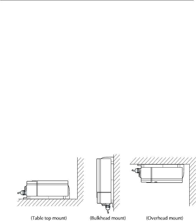
When planning the installation of your RAY230/E, the following conditions
should be considered to ensure dependable and trouble-free operation.
•The mounting location of the primary cradle and handset should allow
easy access from where the ship is normally navigated.
•The Base Station transceiver and Handset should be located at least 3
feet from the antenna.
•There should be adequate ventilation for the Base Station transceiver.
•A sufficient space should be secured behind the transceiver to allow for
proper cable connections to the rear panel connectors.
•The transceiver should be located as near as possible to the power source
•The selected location should be as far apart as possible from any devices
that may cause interference such as motors, generators, and other on
board electronics.
•The transceiver should be protected from prolonged direct exposure to
rain and salt spray. It is always a good practice to protect your valuable
electronic equipment from the elements as much as possible.
•Use adequately sized wire for all DC power connections and make sure to
solder all in-line connectors or splices.
Figure 2-1 Typical Mounting Methods Figure 2-1 Typical Mounting Methods
Figure 2-1 Typical Mounting Methods Figure 2-1 Typical Mounting Methods
Figure 2-1 Typical Mounting Methods
2-3 Installation
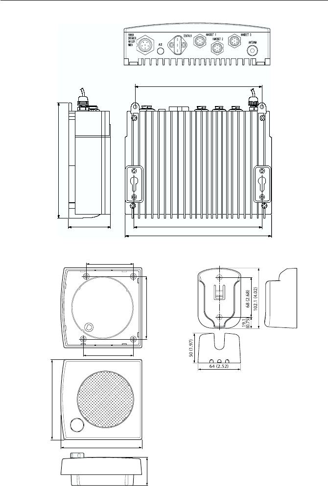
Figure 2-2 Outline and Mounting Dimensions Figure 2-2 Outline and Mounting Dimensions
Figure 2-2 Outline and Mounting Dimensions Figure 2-2 Outline and Mounting Dimensions
Figure 2-2 Outline and Mounting Dimensions
All dimensions are shown in (inches) and millimeters
84 (3.31)
110 (4.33)
25 (.98)
65 (2.56)
70 (2.76)
114 (4.49)
Base Station TransceiverBase Station Transceiver
Base Station TransceiverBase Station Transceiver
Base Station Transceiver
External Speaker UnitExternal Speaker Unit
External Speaker UnitExternal Speaker Unit
External Speaker Unit Cradle Unit Cradle Unit
Cradle Unit Cradle Unit
Cradle Unit
197 (7.76)
200 (7.87)
228 (8.98)
67 (2.63)
1.78 (7.04)
2-4
Installation
2.42.4
2.42.4
2.4 Electrical ConnectionsElectrical Connections
Electrical ConnectionsElectrical Connections
Electrical Connections
2.4.1 DC Power and Hailer/NMEA Cable Connections2.4.1 DC Power and Hailer/NMEA Cable Connections
2.4.1 DC Power and Hailer/NMEA Cable Connections2.4.1 DC Power and Hailer/NMEA Cable Connections
2.4.1 DC Power and Hailer/NMEA Cable Connections
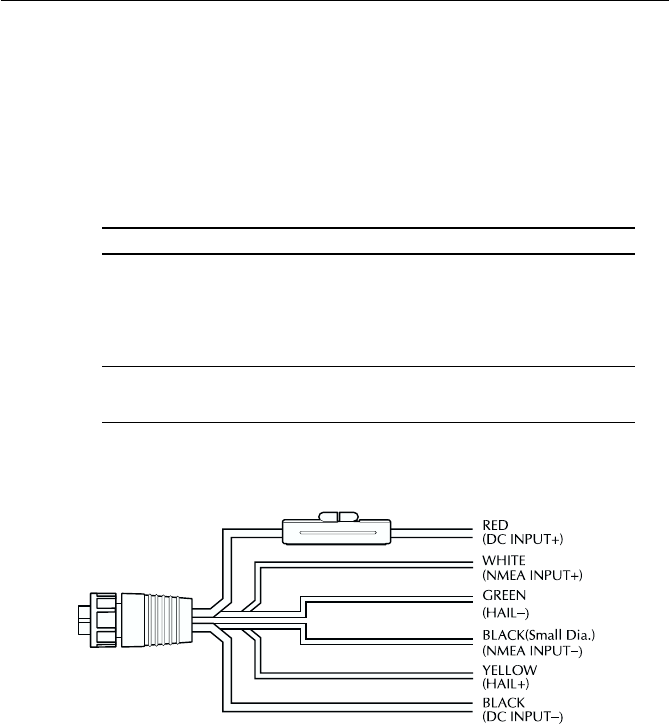
The 6-foot long power cable is a multipurpose assembly containing three
wire-pairs for connections to DC power, NMEA input, and the Hailer Horn
Wire ColorWire Color
Wire ColorWire Color
Wire Color FunctionFunction
FunctionFunction
Function Connects toConnects to
Connects toConnects to
Connects to
RED Power + Ship's 13.2 VDC power
BLACK Power –
YELLOW Hailer + Hailer Horn speaker
GREEN Hailer –
WHITE NMEA + Input from position source (GPS,
BLACK NMEA – LORAN)
The RED (+) power wire contains a 10 amp in-line fuse.
Figure 2-3 Power/Hailer/NMEA Cable and 6-pin ConnectorFigure 2-3 Power/Hailer/NMEA Cable and 6-pin Connector
Figure 2-3 Power/Hailer/NMEA Cable and 6-pin ConnectorFigure 2-3 Power/Hailer/NMEA Cable and 6-pin Connector
Figure 2-3 Power/Hailer/NMEA Cable and 6-pin Connector
speaker. Connections to the 6-pin connector are as follows:
In most cases the length of the power cable should be adequate enough to
reach the DC power source. If additional wire length is required, the cable
can be extended by adding more cable as necessary. However, for power
cable runs longer than 15 feet, larger wire diameter size should be used to
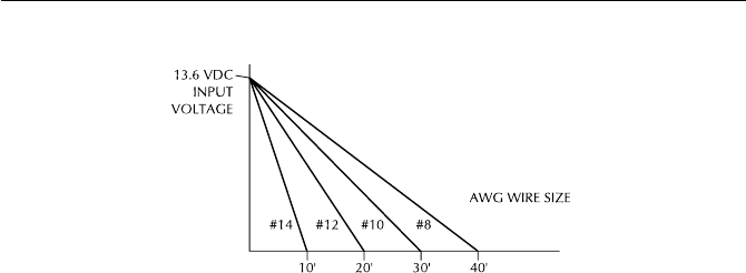
2-5 Installation
prevent voltage line loss.
Your RAY230/E radio should be connected to the nearest primary source
of ship's DC power. A typical source may be a circuit breaker on the power
panel or a fuse block near the unit. When connecting to either of these
sources, the circuit breaker or other in-line fuse should be rated at 10 amps.
It is recommended that lugs be used to connect the power cable to the DC
supply and the lug connections should be both crimped and soldered.
This is very important in order to ensure adequate current draw to the
equipment. If an insufficient connection is made to the power source, the
unit may not work properly. The connection terminal should be clean, with
no sign of corrosion.
The RED (+) wire is connected to the positive terminal of the power source.
The BLACK (-) wire is connected to the negative (ground) of the power
source. Should the power connections be inadvertently reversed, the unit
will not power up but no damage will occur. Simply check the polarity with
a VOM (Voltage/Ohm Meter) and reconnect observing correct polarity. If
the fuse ever needs replacement, be sure to use the same type and rating.
2.4.22.4.2
2.4.22.4.2
2.4.2 Hailer Cable ConnectionsHailer Cable Connections
Hailer Cable ConnectionsHailer Cable Connections
Hailer Cable Connections
The YELLOW (+) wire and GREEN (-) wire are used for connecting the
RAY230/RAY230E to a Hailer Horn speaker. (Refer to Figure 2-3)
Three watts of audio output power are provided for an external 4 ohm
speaker. A suitable speaker can be purchased from your local marine dealer.
Connect the YELLOW (+) wire and GREEN (-) wire to the speaker observing
polarity as it is marked on the speaker. When connected, the external
Figure 2-4 Power Cable LengthFigure 2-4 Power Cable Length
Figure 2-4 Power Cable LengthFigure 2-4 Power Cable Length
Figure 2-4 Power Cable Length
2-6
Installation
speaker will function simultaneously with the internal speaker.
2.4.3 NMEA Data2.4.3 NMEA Data
2.4.3 NMEA Data2.4.3 NMEA Data
2.4.3 NMEA Data
The RAY230/E accepts NMEA 0183 data from a position determining device
(GPS, Loran, etc.) to provide the Latitude and Longitude position
information that is transmitted during a DSC Distress Call. The NMEA
sentences that provide positional data, by order of priority are: GGA, RMC,
RMA, and GLL.
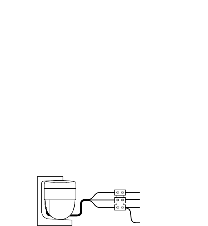
Connect the input(s) of the positioning device to the white (NMEA+) and
black (NMEA-) wires in the Power/Hailer/NMEA cable.
For example, to connect a Raymarine Heading Sensor to the NMEA input,
connect the cables and power supply using a suitable connector block, as
shown in the diagram below. If installed, it may be convenient to connect
the power to the SeaTalk auxiliary junction box described in the following
section.
Note:
All return connections (-) must be tied to a common ground reference.
2.4.4 Using the SeaTalk Auxiliary Junction Box2.4.4 Using the SeaTalk Auxiliary Junction Box
2.4.4 Using the SeaTalk Auxiliary Junction Box2.4.4 Using the SeaTalk Auxiliary Junction Box
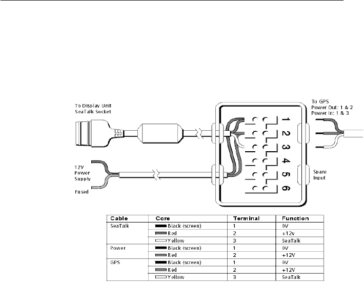
2.4.4 Using the SeaTalk Auxiliary Junction Box
A junction box is used to connect the SeaTalk instrument system to the
RAY230. This junction box enables the SeaTalk bus, power and GPS to be
connected.
If power is not already available (via another SeaTalk instrument), the
junction box can be used to apply power to the SeaTalk bus for other
applications. The junction box may also be used for connecting an NMEA
GPS system.
+12 V
0V
+ NMEA Data (white)
-- NMEA Data (black)
Red
Black
Yellow
Figure 2-5 Sample GPS ConnectionsFigure 2-5 Sample GPS Connections
Figure 2-5 Sample GPS ConnectionsFigure 2-5 Sample GPS Connections
Figure 2-5 Sample GPS Connections
2-7 Installation
2.4.52.4.5
2.4.52.4.5
2.4.5 Antenna ConnectionsAntenna Connections
Antenna ConnectionsAntenna Connections
Antenna Connections
Your coaxial VHF antenna cable connects to the RAY230/E antenna cable
on the rear panel using a PL259 VHF type connector. Your VHF antenna
cable can be cut to length but the overall cable length can be critical to
performance. If you are uncertain, contact a professional installer or call
Raymarine Customer Service. If a longer cable length is required, RG-58
(50 ohm) coaxial cable or equivalent cable can be used for runs up to a
maximum of 50 feet. If the distance required is even greater, we recommend
using low loss RG-213 or equivalent cable for the entire run to avoid
excessive losses in power output.
If the antenna RF connector is likely to be exposed to the marine
environment, a protective coating of grease (Dow Corning DC-4 or similar)
can be applied to the connector before connecting it to the radio. Any
other extensions or adapters in the cable run should also be protected by
silicon grease and then wrapped with a waterproofing tape.
The junction box includes:
•SeaTalk cable and connector to attach to display unit
•Power cable to connect to 12 V power (if required)
•Input connections to connect SeaTalk cable from external equipment
•Spare connections for another instrument
The illustration below shows how to connect the junction box.
Figure 2-6 SeaTalk Junction Box ConnectionsFigure 2-6 SeaTalk Junction Box Connections
Figure 2-6 SeaTalk Junction Box ConnectionsFigure 2-6 SeaTalk Junction Box Connections
Figure 2-6 SeaTalk Junction Box Connections
2-8 Installation
2.4.62.4.6
2.4.62.4.6
2.4.6 Antenna Mounting SuggestionsAntenna Mounting Suggestions
Antenna Mounting SuggestionsAntenna Mounting Suggestions
Antenna Mounting Suggestions
The best radio in the world is useless without a quality antenna and good
location. Mounting the VHF antenna properly is very important because it
will directly affect the performance of your VHF radio. A VHF antenna
designed for marine vessels should be used.
•Since VHF transmission is essentially line-of-sight, mount the antenna at
the highest possible location on the vessel and free of obstruction to
obtain maximum range.
•If you must extend the length of the coaxial cable between the antenna
and the radio, use a coaxial cable designed for the least amount of power
loss over the entire cable length.
•Keep the coaxial cable between the radio and antenna as short as possible
but remember to maintain the recommended 3 feet between the radio and
antenna.
2.4.72.4.7
2.4.72.4.7
2.4.7 GroundingGrounding
GroundingGrounding
Grounding
While special grounding is not generally required for VHF radiotelephone
installations, it is good marine practice to properly ground all electronic
equipment to the ship's ground system. The RAY230/E can be connected
to ground by attaching a wire to one of the screws on the unit's rear panel
and then to the nearest ship's ground connection point. The recommended
wire to be used for such grounding is #10 AWG.
Figure 2-7 Typical Grounding MethodsFigure 2-7 Typical Grounding Methods
Figure 2-7 Typical Grounding MethodsFigure 2-7 Typical Grounding Methods
Figure 2-7 Typical Grounding Methods
3-1
Operations
SECTION 3SECTION 3
SECTION 3SECTION 3
SECTION 3 OPERATIONSOPERATIONS
OPERATIONSOPERATIONS
OPERATIONS
3.13.1
3.13.1
3.1 IntroductionIntroduction
IntroductionIntroduction
Introduction
The RAY230 has the capability to transmit and receive on all available US,
Canadian, and International Marine VHF radiotelephone channels. The
RAY230E can transmit and receive on all available International and US
Marine VHF radiotelephone channels. There are channels that are FCC
approved but may only be used by authorized stations for specific
purposes, depending on the type of vessel (commercial or non-commercial.)
Refer to Table 3.5.31, which lists all marine VHF channels available in your
RAY230/RAY230E for US, International and Canadian radiotelephone use.
Full familiarization of these tables is essential when selecting your channels
to ensure proper channel usage.
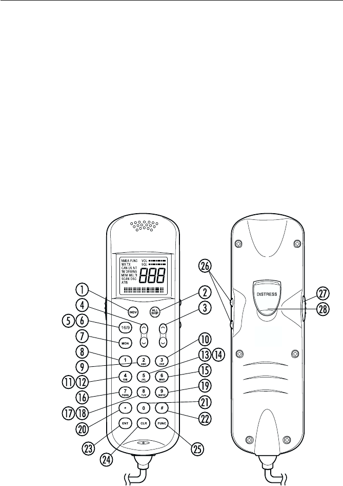
Figure 3-1 Layout of Controls

3-2 Operations
3.23.2
3.23.2
3.2 Controls and LCD DisplayControls and LCD Display
Controls and LCD DisplayControls and LCD Display
Controls and LCD Display
3.2.1 Controls3.2.1 Controls
3.2.1 Controls3.2.1 Controls
3.2.1 Controls
INDV keyINDV key
INDV keyINDV key
INDV key
Switches to the DSC Individual Ships Call mode for initiating ship-to-
ship or ship-to-shore calls using a specific MMSI number. Descriptions
of subsequent operations appear below in sections 3.5.26.1 and
3.5.26.2.
ALL SHIP keyALL SHIP key
ALL SHIP keyALL SHIP key
ALL SHIP key
Switches to the All Ships Call mode for Safety and Urgency
transmissions. Descriptions of subsequent operations appear below
in section 3.5.26.5 Transmitting All Ships Call.
!
SQ UP/DOWN (SCROLL) keySQ UP/DOWN (SCROLL) key
SQ UP/DOWN (SCROLL) keySQ UP/DOWN (SCROLL) key
SQ UP/DOWN (SCROLL) key
Increases or decreases the squelch sensitivity. Pressing the UP
∧∧
∧∧
∧
key increases the squelch, while the DOWN
∨∨
∨∨
∨
key decreases it. The
number of segments in the SQ bar graph on the LCD display will
increase or decrease accordingly. This key is also used as a scroll key
for changing the channel number and other settings, as described
below.
"
VOL UP/DOWN keyVOL UP/DOWN key
VOL UP/DOWN keyVOL UP/DOWN key
VOL UP/DOWN key
Changes the sound volume of the handset. Pressing the UP
∧∧
∧∧
∧
key
increases the volume, while the DOWN
∨∨
∨∨
∨
key causes it to decrease.
The number of segments in the VOL bar graph on the LCD display
will increase or decrease accordingly.
#16/9 key (RAY230 US version only)16/9 key (RAY230 US version only)
16/9 key (RAY230 US version only)16/9 key (RAY230 US version only)
16/9 key (RAY230 US version only)
Switches between the Working Channel and the Priority Channel.
Pressing and holding the key for 2 seconds alternates the Priority
Channel between channel 9 and channel 16. When the transceiver’s
main power switch is turned on, this key is also used to power the
system ON or OFF.
$16 key (RAY230E European version only)16 key (RAY230E European version only)
16 key (RAY230E European version only)16 key (RAY230E European version only)
16 key (RAY230E European version only)
Switches between the Working Channel and Channel 16 (the Priority
Channel).

3-3
Operations
%
MON/TRI keyMON/TRI key
MON/TRI keyMON/TRI key
MON/TRI key
Starts the Dual-Watch monitor mode. Pressing the FUNC key followed
by the MON/TRI key initiates the Tri-Watch monitor mode.
&
1/MEM key1/MEM key
1/MEM key1/MEM key
1/MEM key
This key inputs the number 1. When an alphanumeric response is
appropriate, this key alternates between entering a 1 and a space. If
the channel number indicated on the LCD display is not currently
stored in memory, pressing the FUNC key followed by the 1/MEM
key enters that channel number into memory. If the currently indicated
channel has already been stored, pressing the FUNC key followed by
the 1/MEM key deletes that channel from memory.
'
2/SCAN key2/SCAN key
2/SCAN key2/SCAN key
2/SCAN key
This key inputs the number 2. When an alphanumeric response is
appropriate, each press of this key alternately inputs the characters
A, B, C, then 2. Pressing the FUNC key followed by the 2/SCAN key
toggles Scan mode ON or OFF. Scan mode is described below in
Section 3.5.21.
3/CELL key3/CELL key
3/CELL key3/CELL key
3/CELL key
This key inputs the number 3. When an alphanumeric response is
appropriate, each press of this key alternately inputs the characters
D, E, F, then 3. Pressing the FUNC key followed by the 3/CELL key
connects the handset with any auxiliary communication equipment
with DTMF interface (RAYCOM Cellular, Mini-M, etc.) connected to
the AUX port at the rear of the transceiver. See section 3.5.19.
4/INT key (RAY230 only)4/INT key (RAY230 only)
4/INT key (RAY230 only)4/INT key (RAY230 only)
4/INT key (RAY230 only)
This key inputs the number 4. When an alphanumeric response is
appropriate, each press of this key alternately inputs the characters G,
H, I, then 4. Pressing the FUNC key followed by the 4/INT key alternates
the frequency groups from US mode to International mode to Canadian
mode.
4/US key (RAY230E only)4/US key (RAY230E only)
4/US key (RAY230E only)4/US key (RAY230E only)
4/US key (RAY230E only)
This key inputs the number 4. When an alphanumeric response is
appropriate, each press of this key alternately inputs the characters G,
H, I, then 4. Pressing the FUNC key followed by the 4/US key alternates
the frequency groups between US mode and International mode.

3-4 Operations
!
5 key (RAY230 only)5 key (RAY230 only)
5 key (RAY230 only)5 key (RAY230 only)
5 key (RAY230 only)
This key inputs the number 5. When an alphanumeric response is
appropriate, each press of this key alternately inputs the characters J,
K, L, then 5.
"
5/PRIV key (RAY230E only)5/PRIV key (RAY230E only)
5/PRIV key (RAY230E only)5/PRIV key (RAY230E only)
5/PRIV key (RAY230E only)
This key inputs the number 5. When an alphanumeric response is
appropriate, each press of this key alternately inputs the characters J,
K, L, then 5. Pressing the FUNC key followed by the 5/PRIV key
switches to the Private Channel mode. To select the desired Private
Channel, press the FUNC key followed by the 5/PRIV key, then input
the number key(s) corresponding to the desired channel number and
press ENT.
#
6/WX key6/WX key
6/WX key6/WX key
6/WX key
This key inputs the number 6. When an alphanumeric response is
appropriate, each press of this key alternately inputs the characters
M, N, O, then 6. Pressing the FUNC key followed by the 6/WX key
alternates between the Working Channel and the Weather Channel.
For the RAY230E European model, this operation is valid only in US
frequency mode.
$
7/ D/L key7/ D/L key
7/ D/L key7/ D/L key
7/ D/L key
This key inputs the number 7. When an alphanumeric response is
appropriate, each press of this key alternately inputs the characters P,
Q, R, S, then 7. Pressing the FUNC key followed by the 7/D/L key
toggles between full receiver sensitivity (distant mode) and attenuated
receiver sensitivity (local mode). Local mode is used in high traffic
areas to decrease unwanted reception. While in local mode (receiver
is desensitized), the DESENS indicator appears in the LCD display.
% 8 key (RAY230 only)8 key (RAY230 only)
8 key (RAY230 only)8 key (RAY230 only)
8 key (RAY230 only)
This key inputs the number 8. When an alphanumeric response is
appropriate, each press of this key alternately inputs the characters
T, U, V, then 8.
& 8/ M-CALL key (RAY230E only)8/ M-CALL key (RAY230E only)
8/ M-CALL key (RAY230E only)8/ M-CALL key (RAY230E only)
8/ M-CALL key (RAY230E only)
This key inputs the number 8. When an alphanumeric response is
appropriate, each press of this key alternately inputs the characters
T, U, V, then 8. Pressing the FUNC key followed by the 8/M-CALL key
starts Multi-Call mode. If the key is pressed during Multi-Call mode,
the operation returns to normal mode.

3-5
Operations
'
9/ 1/25 key9/ 1/25 key
9/ 1/25 key9/ 1/25 key
9/ 1/25 key
This key inputs the number 9. When an alphanumeric response is
appropriate, each press of this key alternately inputs the characters
W, X, Y, Z, and then 9. Pressing the FUNC key followed by the 9/1/25
key alternates the transmission power between 1W and 25W.
*/HAIL key*/HAIL key
*/HAIL key*/HAIL key
*/HAIL key
This key inputs an asterisk (*). Pressing the FUNC key followed by
the */HAIL key initiates the Hailer mode, which enables a Hailer Horn
speaker to be used as a loud speaker or a directional microphone.
Pressing this key during Hailer mode returns operation to normal
mode.
0/IC key0/IC key
0/IC key0/IC key
0/IC key
This key inputs the number 0. Pressing the FUNC key followed by the
0/IC key starts Intercom mode, which enables conversation between
handsets. Pressing this key during Intercom mode returns operation
to normal mode.
#/FOG key#/FOG key
#/FOG key#/FOG key
#/FOG key
This key inputs the # character. Pressing the FUNC key followed by
the #/FOG key initiates the Fog Alert mode, which enables a Hailer
Horn speaker to sound several types of automatic or manual alert
tones.
!
ENT/MENU keyENT/MENU key
ENT/MENU keyENT/MENU key
ENT/MENU key
This key performs the Enter function. It is used to confirm and
implement an input action. Pressing the FUNC key followed by the
ENT/MENU key initiates the Menu mode. Pressing the key during
Menu mode returns the operation to normal mode.
" CLR/LOG keyCLR/LOG key
CLR/LOG keyCLR/LOG key
CLR/LOG key
Depending on when it is used, this key exits the current mode and
reverts to the last used mode or normal operation. This key also can
be used to clear any alphanumeric inputs one at a time in the order
that they were entered. Pressing the FUNC key followed by CLR/LOG
key initiates the Digital Selective Calling (DSC) Log. Pressing the key
during logging returns operation to normal mode.
# FUNC/DIM keyFUNC/DIM key
FUNC/DIM keyFUNC/DIM key
FUNC/DIM key
Initiates the Function mode and activates the FUNC indicator in the
LCD display. The next key pressed determines the function selected.
(See above key descriptions.) Pressing this key twice starts Dimmer
mode, which reduces the brightness of LCD's backlight.
3-6 Operations
$ Channel UP/ DOWN switchChannel UP/ DOWN switch
Channel UP/ DOWN switchChannel UP/ DOWN switch
Channel UP/ DOWN switch
Pressing this switch during normal operation changes the channel
number UP or DOWN.
% PTT (Press-to-Talk) switchPTT (Press-to-Talk) switch
PTT (Press-to-Talk) switchPTT (Press-to-Talk) switch
PTT (Press-to-Talk) switch
Pressing this switch during normal operation places the radio in
Transmit mode and displays the TX indicator in the LCD. When the
switch is pressed in various function modes, the assigned operation
is initiated.
Note: After 5 minutes of continuously holding the PTT switch, the radio
will automatically stop transmitting so that it can receive any incoming
messages. To begin transmitting again, release the PTT and depress again.
&
DISTRESS switchDISTRESS switch
DISTRESS switchDISTRESS switch
DISTRESS switch
This switch is located under the small door labeled DISTRESS on the
back of the handset. Pressing and holding this switch for 4 seconds
selects Distress Signal Call mode. Subsequent operations are
described in section 3.5.26.7.
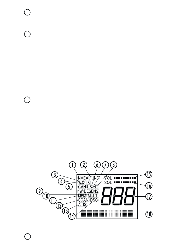
3.2.2 LCD Display3.2.2 LCD Display
3.2.2 LCD Display3.2.2 LCD Display
3.2.2 LCD Display
The following describes the functional characters on the RAY230/RAY230E
Handset's LCD.
NMEA indicatorNMEA indicator
NMEA indicatorNMEA indicator
NMEA indicator
Displayed when the radio receives valid SeaTalk or NMEA position
data. If the data is invalid or no data is received for a period of time,
the indicator disappears.
Figure 3-2 LCD Display Layout

3-7
Operations
FUNC indicatorFUNC indicator
FUNC indicatorFUNC indicator
FUNC indicator
Displayed when the FUNC key is pressed. Disappears when another
key is pressed, or after no other key is pressed for a period of time.
!
WX indicatorWX indicator
WX indicatorWX indicator
WX indicator
Displayed while in Weather Channel or Tri-Watch monitor mode. For
the RAY230E, this indicator only appears in the US frequency mode.
"
TX indicatorTX indicator
TX indicatorTX indicator
TX indicator
Displayed while transmitting.
#CAN indicator (RAY230 only)CAN indicator (RAY230 only)
CAN indicator (RAY230 only)CAN indicator (RAY230 only)
CAN indicator (RAY230 only)
Displayed when the Canadian frequency group is selected.
$US indicatorUS indicator
US indicatorUS indicator
US indicator
Displayed when the US frequency group is selected.
%DESENS indicatorDESENS indicator
DESENS indicatorDESENS indicator
DESENS indicator
Displayed during the desensitized receiving (local) mode.
&INT indicatorINT indicator
INT indicatorINT indicator
INT indicator
Displayed when the International frequency group is selected.
'1W indicator1W indicator
1W indicator1W indicator
1W indicator
Displayed when the transmission power of 1W is selected with the
9/1/25 key or when a low power channel is selected.
MULTI indicator (RAY230E only)MULTI indicator (RAY230E only)
MULTI indicator (RAY230E only)MULTI indicator (RAY230E only)
MULTI indicator (RAY230E only)
Displayed while the channel stored in Multi-Call memory is displayed.
MEM indicatorMEM indicator
MEM indicatorMEM indicator
MEM indicator
Displayed while the channel stored in memory is displayed. This
indicator flashes before the start of the memory scan operation.
SCAN indicatorSCAN indicator
SCAN indicatorSCAN indicator
SCAN indicator
Displayed during Scan mode. If channels have been stored in memory,
this indicator will be flashing before the start of Scan mode.
MEM indicatorMEM indicator
MEM indicatorMEM indicator
MEM indicator
Displayed while the channel stored in memory is displayed. This
indicator flashes before the start of the memory scan operation.
!
ATIS indicatorATIS indicator
ATIS indicatorATIS indicator
ATIS indicator
Displayed when the ATIS (automatic identification transmission)
feature is turned on (via the Menu mode).

3-8 Operations
"
DSC indicatorDSC indicator
DSC indicatorDSC indicator
DSC indicator
Displayed when in a Digital Selective Calling (DSC) call mode, DSC
log, or the DSC menu.
#
VOL indicator (in bar graph)VOL indicator (in bar graph)
VOL indicator (in bar graph)VOL indicator (in bar graph)
VOL indicator (in bar graph)
Represents the current sound volume level of the handset. A louder
volume displays a larger number of segments in the bar graph. This
bar graph is not displayed during Menu mode.
$
SQL indicator (in bar graph)SQL indicator (in bar graph)
SQL indicator (in bar graph)SQL indicator (in bar graph)
SQL indicator (in bar graph)
Represents the current squelch level. A deeper squelch displays a
larger number of segments in the bar graph.
% Three-digit, Seven-segment indicatorsThree-digit, Seven-segment indicators
Three-digit, Seven-segment indicatorsThree-digit, Seven-segment indicators
Three-digit, Seven-segment indicators
Display the channel number or state of the radio.
& Nine-digit Dot-matrix displayNine-digit Dot-matrix display
Nine-digit Dot-matrix displayNine-digit Dot-matrix display
Nine-digit Dot-matrix display
Displays alphanumeric messages, modes, and functional status of
the radio.
3.33.3
3.33.3
3.3 Radio FunctionsRadio Functions
Radio FunctionsRadio Functions
Radio Functions
3.3.1 RAY230 US Version3.3.1 RAY230 US Version
3.3.1 RAY230 US Version3.3.1 RAY230 US Version
3.3.1 RAY230 US Version
1)1)
1)1)
1) Selecting the Frequency ModeSelecting the Frequency Mode
Selecting the Frequency ModeSelecting the Frequency Mode
Selecting the Frequency Mode
Channel selection is available from among three frequency groups:
US, International, or Canadian.
2)2)
2)2)
2) Receiving the Weather ChannelsReceiving the Weather Channels
Receiving the Weather ChannelsReceiving the Weather Channels
Receiving the Weather Channels
The RAY230 is programmed to receive 10 NOAA weather channels
and will sound an alarm if a Weather Alert is received.
4)4)
4)4)
4) Selecting the Priority ChannelSelecting the Priority Channel
Selecting the Priority ChannelSelecting the Priority Channel
Selecting the Priority Channel
Select Channel 16 or Channel 9 as the Priority Channel.
5)5)
5)5)
5) Dimmer OperationDimmer Operation
Dimmer OperationDimmer Operation
Dimmer Operation
Select from four LCD backlight levels, including OFF.
6)6)
6)6)
6) Monitor OperationMonitor Operation
Monitor OperationMonitor Operation
Monitor Operation
Select from Dual-Watch or Tri-Watch mode.
7)7)
7)7)
7) Scan OperationScan Operation
Scan OperationScan Operation
Scan Operation
Select from All Scan or Memory Scan.
8)8)
8)8)
8) Selecting Transmission Power OutputSelecting Transmission Power Output
Selecting Transmission Power OutputSelecting Transmission Power Output
Selecting Transmission Power Output
Select either 1W or 25W for the transmission power.

3-9
Operations
9)9)
9)9)
9) Digital Selective Calling (DSC) OperationDigital Selective Calling (DSC) Operation
Digital Selective Calling (DSC) OperationDigital Selective Calling (DSC) Operation
Digital Selective Calling (DSC) Operation
Conforms to all class D functionality of a VHF DSC radio in accordance
with RTCM SC-101 and ITU 493. These functions include Individual
Ships Call, All Ships Call, Distress Call, Group Call, and DSC logging
capability.
10)10)
10)10)
10) NMEA Receiving OperationNMEA Receiving Operation
NMEA Receiving OperationNMEA Receiving Operation
NMEA Receiving Operation
Positional information from external equipment is obtained using the
NMEA 0183 interface. Receivable commands are limited to the position
commands of GGA, GLL, RMC, and RMA and to the status commands
of RMC, APB, GLL, and APA.
11)11)
11)11)
11) SeaTalk OperationSeaTalk Operation
SeaTalk OperationSeaTalk Operation
SeaTalk Operation
Position data from other Raymarine equipment is obtained using the
SeaTalk line.
12)12)
12)12)
12) Remote OperationRemote Operation
Remote OperationRemote Operation
Remote Operation
Up to three full function handsets can be connected to the RAY230.
Auxiliary handsets can be housed in the cradle, enabling you to listen
to radio reception from the external speaker.
13)13)
13)13)
13) Intercom Function between HandsetsIntercom Function between Handsets
Intercom Function between HandsetsIntercom Function between Handsets
Intercom Function between Handsets
The Intercom function is available when two or more handsets are
connected.
14)14)
14)14)
14) Reduced Receiving Sensitivity (Local Mode)Reduced Receiving Sensitivity (Local Mode)
Reduced Receiving Sensitivity (Local Mode)Reduced Receiving Sensitivity (Local Mode)
Reduced Receiving Sensitivity (Local Mode)
This function decreases receiver sensitivity in high traffic areas to
decrease unwanted reception.
15)15)
15)15)
15) Hailer OperationHailer Operation
Hailer OperationHailer Operation
Hailer Operation
The Hailer Horn speaker can be used as a loud speaker or a directional
microphone.
16)16)
16)16)
16) Fog Horn OperationFog Horn Operation
Fog Horn OperationFog Horn Operation
Fog Horn Operation
The Hailer Horn speaker can sound several types of fog alerts.
17)17)
17)17)
17) Cellular Phone OperationCellular Phone Operation
Cellular Phone OperationCellular Phone Operation
Cellular Phone Operation
By connecting an optional RAYCOM Cellular Fixed Wireless Terminal
(or other DTMF formatted communications device, such as the Mini-
M) to the AUX terminal, the handset can be used as a cellular phone.
See section 3.5.19.

3-10 Operations
3.3.2 RAY230E European Version3.3.2 RAY230E European Version
3.3.2 RAY230E European Version3.3.2 RAY230E European Version
3.3.2 RAY230E European Version
1) 1)
1) 1)
1) Selecting the Frequency ModeSelecting the Frequency Mode
Selecting the Frequency ModeSelecting the Frequency Mode
Selecting the Frequency Mode
Channel selection is available from two frequency groups: US and
International. In the US mode, the radio only has access to US
channels.
2)2)
2)2)
2) Private Channel OperationPrivate Channel Operation
Private Channel OperationPrivate Channel Operation
Private Channel Operation
Any of the channels from Channel 1 to Channel 10 can be designated
as the Private Channel.
3)3)
3)3)
3) Multi-call OperationMulti-call Operation
Multi-call OperationMulti-call Operation
Multi-call Operation
The Multi-Call function stores in memory up to 8 channels for each of
the 2 frequency groups.
4)4)
4)4)
4) Weather Channel Access OperationWeather Channel Access Operation
Weather Channel Access OperationWeather Channel Access Operation
Weather Channel Access Operation
The RAY230E is programmed to receive 10 NOAA weather channels
and will sound an alarm if a Weather Alert is received. This operation
is available only in US frequency mode.
5)5)
5)5)
5) Channel Memory OperationChannel Memory Operation
Channel Memory OperationChannel Memory Operation
Channel Memory Operation
Channels that are stored in memory in the same frequency group can
be scanned using the Memory Channel Scan function.
6)6)
6)6)
6) Priority Channel OperationPriority Channel Operation
Priority Channel OperationPriority Channel Operation
Priority Channel Operation
Channel 16 is designated as the Priority Channel.
7)7)
7)7)
7) Dimmer OperationDimmer Operation
Dimmer OperationDimmer Operation
Dimmer Operation
Select from four LCD backlight levels, including OFF.
8)8)
8)8)
8) Monitor OperationMonitor Operation
Monitor OperationMonitor Operation
Monitor Operation
Select from Dual-Watch or Tri-Watch mode.
9)9)
9)9)
9) Scan OperationScan Operation
Scan OperationScan Operation
Scan Operation
Select from All Scan or Memory Scan.
10)10)
10)10)
10) Selecting Transmission Power OutputSelecting Transmission Power Output
Selecting Transmission Power OutputSelecting Transmission Power Output
Selecting Transmission Power Output
Select either 1W or 25W for the transmission power.
11)11)
11)11)
11) Digital Selective Calling (DSC) OperationDigital Selective Calling (DSC) Operation
Digital Selective Calling (DSC) OperationDigital Selective Calling (DSC) Operation
Digital Selective Calling (DSC) Operation
This operation conforms to EN 301 025 in accordance with ITU-RM493.
These functions include Individual Ships Call, All Ships Call, Distress
Call, Group Call, and DSC logging capability.
12)12)
12)12)
12) NMEA Receiving OperationNMEA Receiving Operation
NMEA Receiving OperationNMEA Receiving Operation
NMEA Receiving Operation
Positional information from external equipment is obtained using the
NMEA 0183 interface. Receivable commands are limited to the position
commands of GGA, GLL, RMC, and RMA and to the status commands
of RMC, APB, GLL, and APA.

3-11
Operations
13)13)
13)13)
13) ATIS OperationATIS Operation
ATIS OperationATIS Operation
ATIS Operation
When operating in inland waterways, many European countries require
automatic identification transmission, in accordance with ETS300 698.
The RAY230E has the capability of activating this ATIS function.
This radio is also equipped with “ATIS Killer” to squelch unwanted
electrical noise associated with ATIS transmissions.
14)14)
14)14)
14) SeaTalk OperationSeaTalk Operation
SeaTalk OperationSeaTalk Operation
SeaTalk Operation
Position data from other Raymarine equipment is obtained using the
SeaTalk line.
15)15)
15)15)
15) Remote OperationRemote Operation
Remote OperationRemote Operation
Remote Operation
Up to three full function handsets can be connected to the RAY230E.
Auxiliary handsets can be housed in the cradle, enabling you to listen
to radio reception from the external speaker.
16)16)
16)16)
16) Intercom Function between HandsetsIntercom Function between Handsets
Intercom Function between HandsetsIntercom Function between Handsets
Intercom Function between Handsets
The Intercom function is available when two or more handsets are
connected.
17)17)
17)17)
17) Reduced Receiving Sensitivity (Local Mode)Reduced Receiving Sensitivity (Local Mode)
Reduced Receiving Sensitivity (Local Mode)Reduced Receiving Sensitivity (Local Mode)
Reduced Receiving Sensitivity (Local Mode)
This function decreases receiver sensitivity in high traffic areas to
decrease unwanted reception.
18)18)
18)18)
18) Hailer OperationHailer Operation
Hailer OperationHailer Operation
Hailer Operation
The Hailer Horn can be used as a loud speaker or a directional
microphone.
19)19)
19)19)
19) Fog Horn OperationFog Horn Operation
Fog Horn OperationFog Horn Operation
Fog Horn Operation
The Hailer Horn speaker can sound several types of manual and auto
fog alerts.
20)20)
20)20)
20) Cellular Phone OperationCellular Phone Operation
Cellular Phone OperationCellular Phone Operation
Cellular Phone Operation
By connecting an optional RAYCOM Cellular Fixed Wireless Terminal
(or other DTMF formatted communications device, such as the Mini-
M) to the AUX terminal, the handset can be used as a cellular phone.
See section 3.5.19.
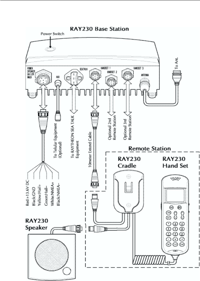
3-12 Operations
3.43.4
3.43.4
3.4 Equipment ConnectionsEquipment Connections
Equipment ConnectionsEquipment Connections
Equipment Connections

3-13
Operations
3.53.5
3.53.5
3.5 Operating ProceduresOperating Procedures
Operating ProceduresOperating Procedures
Operating Procedures
With the RAY230 and RAY230E, all operations are made on the Handset
except turning ON/OFF the main power supply and adjusting the sound
volume of the External Speaker.
3.5.1 Turning ON/ OFF the Power Supply3.5.1 Turning ON/ OFF the Power Supply
3.5.1 Turning ON/ OFF the Power Supply3.5.1 Turning ON/ OFF the Power Supply
3.5.1 Turning ON/ OFF the Power Supply
To power on the RAY230/E:
1) Press the main power supply button located on the top of the base
station transceiver (main unit). A light illuminates the button when
power is ON.
The main unit and the handset(s) will then be in a standby power
condition; the radio circuitry does not yet have power.
2) Press the 16/9 key on any handset. The full system is powered ON.
Note:
If the main power supply switch is OFF, the handsets cannot power the
system ON.
If the main power supply switch is ON and multiple handsets are connected,
pressing the FUNC and 16/9 key from one handset will fully power ON
the system and all handsets.
To power off the RAY230/E:
1) Press the FUNC key followed by the 16/9 key on any handset. The
main unit and all handset(s) return to the standby condition.
2) Switch OFF the main power supply. The light illuminating the button
goes out. Full system power is OFF.
Note:
If multiple handsets are connected, initiating power OFF from one handset
will cause all the handsets (and main unit) to enter the standby condition.
Power OFF can be only be initiated from the handset that has priority.
See section 3.5.23 below.

3-14 Operations
3.5.2 Setting the Volume3.5.2 Setting the Volume
3.5.2 Setting the Volume3.5.2 Setting the Volume
3.5.2 Setting the Volume
Setting the Volume on the Handset
The sound volume adjustment for the handset has 11 settings. Pressing
and releasing the VOL UP
∧∧
∧∧
∧
key increases the volume by one level;
pressing and releasing the VOL DOWN
∨∨
∨∨
∨
key reduces the volume by one
level.
The number of segments in the VOL bar graph on the LCD display will
increase or decrease accordingly. If the VOL UP/DOWN keys are pressed
and held, the volume levels will automatically change every half-second.
Setting the Volume on the External Speaker
The volume knob on the External Speaker controls its sound volume.
Turning the knob clockwise increases the volume; turning it
counterclockwise reduces the volume.
Turning the knob fully counterclockwise turns off the volume completely.
However, when an alert is received, the tone is sounded at maximum volume
regardless of the volume set with the knob.
3.5.3 Setting the Squelch3.5.3 Setting the Squelch
3.5.3 Setting the Squelch3.5.3 Setting the Squelch
3.5.3 Setting the Squelch
The squelch adjustment enables you to "quiet" the receiver when no
signal is being received. The squelch adjustment for the handset has 11
settings. Pressing and releasing the SQ UP
∧∧
∧∧
∧
key increases the squelch
by one level; pressing and releasing the SQ DOWN
∨∨
∨∨
∨
key decreases it by
one level. The number of segments in the SQ bar graph on the LCD display
will increase or decrease accordingly. If the SQ UP/DOWN keys are pressed
and held, the squelch levels will automatically change every half-second.
3.5.4 Using the Function Key3.5.4 Using the Function Key
3.5.4 Using the Function Key3.5.4 Using the Function Key
3.5.4 Using the Function Key
Most of the keys on the handset control multiple operations. Pressing one
of these keys after pressing the FUNC key initiates the operation marked
on the label above that key. When the FUNC key is pressed, the FUNC
indicator is displayed on the LCD display. If no other key is pressed for 5
seconds, the Function operation is cancelled and the FUNC indicator
disappears.

3-15
Operations
3.5.5 Setting the Frequency Mode (RAY230)3.5.5 Setting the Frequency Mode (RAY230)
3.5.5 Setting the Frequency Mode (RAY230)3.5.5 Setting the Frequency Mode (RAY230)
3.5.5 Setting the Frequency Mode (RAY230)
Select the channel frequency group to be used: US, International, or
Canadian. Indicators displayed in the LCD identify the active frequency
group: US for the US frequency group, INT for the International group,
and CAN for the Canadian group.
Pressing the FUNC key followed by the INT key alternates the frequency
groups from US mode to International mode to Canadian mode then back
to US mode. When the power supply is turned on, the radio is initiated on
the last selected Priority Channel (9 or 16) in the frequency group last
selected.
When the frequency group is changed, the channel number remains the
same as was selected in the previous group, as long as that number is
present in the new group. If a channel number is absent in the destination
group, the new channel will be the previous number plus 1. When returning
to the previous frequency group, the channel returns to its original number
if the channel has not been changed. If the channel has been changed,
that number is retained when the frequency group is changed.
Example 1
CH15 US ⇒ CH15 INT ⇒ CH15 CAN ⇒ CH15 US
When shifting the frequency group, the channel remains the same because
the corresponding channel number exists in the new frequency group.
Example 2
CH2 CAN ⇒ CH3 US ⇒ CH2 INT ⇒ CH2 CAN
No corresponding channel exists in the new frequency group, so the
channel is incremented by 1. As long as the channel is not changed further,
it returns to its previous number if the frequency group is again changed.
Example 3
CH2 CAN ⇒ CH3 US, then changed to CH5 ⇒ CH5 INT ⇒ CH5 CAN
However, if the channel is changed in the new frequency group, this new
number is retained when the frequency group is changed.

3-16 Operations
3.5.6 Setting the Frequency Mode (RAY 230E)3.5.6 Setting the Frequency Mode (RAY 230E)
3.5.6 Setting the Frequency Mode (RAY 230E)3.5.6 Setting the Frequency Mode (RAY 230E)
3.5.6 Setting the Frequency Mode (RAY 230E)
Select the channel frequency group to be used from either US or
International. Indicators displayed in the LCD identify the active frequency
group: US for the US frequency group or INT for the International group.
Changing the frequency group
Pressing the FUNC key followed by the INT key alternates the frequency
groups from US mode to International mode then back to US mode. When
the power supply is turned on, the radio initially operates on Channel 16 in
the frequency group last selected.
When the frequency group is changed, the channel number remains the
same as was selected in the previous group, as long as that number is
present in the new group. If a channel number is absent in the destination
group, the new channel will be the previous number plus 1. When returning
to the previous frequency group, the channel returns to its original number
if the channel has not been changed. If the channel has been changed,
that number is retained when the frequency group is changed.
Refer to the examples in section 3.5.5 above, ignoring the references to the
Canadian frequency group.
3.5.7 Receiving on the Weather Channels3.5.7 Receiving on the Weather Channels
3.5.7 Receiving on the Weather Channels3.5.7 Receiving on the Weather Channels
3.5.7 Receiving on the Weather Channels
The Weather Channels consist of Channel 0 through Channel 9. To switch
between the Working Channel and the current Weather Channel, press the
FUNC key followed by the 6/WX key. While the Weather Channel is active,
the WX indicator is appears in the LCD display and the frequency group
indicator disappears.
If the channel number is changed while in the Weather mode, the new
channel number is stored in memory upon exiting Weather mode. When
the power is turned off, the last-used Weather Channel is retained for use
when the unit is powered back on.
To exit Weather Mode, press CLR, or FUNC followed by 6/WX.

3-17
Operations
3.5.8 Selecting the Channel3.5.8 Selecting the Channel
3.5.8 Selecting the Channel3.5.8 Selecting the Channel
3.5.8 Selecting the Channel
Two methods are available for selecting the channel: inputting the channel
with the numeric keypad then pressing the ENT key or using the Channel
UP/DOWN switch on the side of the handset. Both methods are applicable
to the three frequency groups on the Working Channel.
Using the Channel UP/DOWN Switch
Pressing the Channel UP
∧∧
∧∧
∧
switch increments the current channel number
by one for each key-click. When the highest channel number is reached,
the channel scrolls to the lowest number and increments from there.
Pressing the Channel DOWN
∨∨
∨∨
∨
switch decrements the current channel
number by one for each key-click. When the lowest channel number is
reached, the channel scrolls to the highest number and decrements from
there. Channel numbers not available in a particular frequency group are
skipped.
If the Channel UP/DOWN switch is pressed and held for at least a half
second, channels automatically change every 100 milliseconds.
Using the Numeric Keypad
To select a channel, input the desired number on the keypad. For 5 seconds
the channel number flashes on the LCD display. If the ENT key is pressed
during this 5 second interval, the channel change is implemented. If the 5
seconds elapse without pressing another key, the channel change is
implemented anyway. If the CLR key is pressed while the number is flashing,
the channel returns to the previous number.
Note: A leading zero is required for single digit channel numbers.
3.5.9 Selecting Private Channel (RAY230E)3.5.9 Selecting Private Channel (RAY230E)
3.5.9 Selecting Private Channel (RAY230E)3.5.9 Selecting Private Channel (RAY230E)
3.5.9 Selecting Private Channel (RAY230E)
In the RAY 230E, any of the channels from Channel 1 to Channel 10 can be
designated as the Private Channel. To select the Private Channel, press
the FUNC key, followed by the 5/PRIV key, then input the channel number
on the keypad. For 5 seconds the channel number flashes on the LCD
display. If the ENT key is pressed during this flashing phase, the channel
change is implemented. If the 5 seconds elapse without pressing another
key, the channel change is implemented. If the CLR key is pressed during
the flashing phase, the channel returns to the previous number and an
error alert tone sounds.

3-18 Operations
Note:
While using the Private Channel, changing the channel number or
pressing the CLR key returns operation to the Working Channel.
3.5.10 Priority Channel for RAY2303.5.10 Priority Channel for RAY230
3.5.10 Priority Channel for RAY2303.5.10 Priority Channel for RAY230
3.5.10 Priority Channel for RAY230
In the RAY230 US version, the Priority Channel operates on either Channel
16 or Channel 9. Pressing the 16/9 key during any operation except the
Distress Call switches to the Priority Channel. Pressing and holding the
16/9 key for 2 seconds alternates the Priority Channel between Channel 16
and Channel 9.
While using the Priority Channel, pressing the 16/9 key or the CLR key
returns operation to the Working Channel.
3.5.11 Priority Channel for RAY230E3.5.11 Priority Channel for RAY230E
3.5.11 Priority Channel for RAY230E3.5.11 Priority Channel for RAY230E
3.5.11 Priority Channel for RAY230E
In the RAY230E European version, the Priority Channel operates on
Channel 16. Pressing the 16 key at any state except the Distress Call shifts
operation to the Priority Channel. While using the Priority Channel, pressing
the 16 key or the CLR key returns operation to the Working Channel.
3.5.12 Multi-Call Operation (RAY230E only)3.5.12 Multi-Call Operation (RAY230E only)
3.5.12 Multi-Call Operation (RAY230E only)3.5.12 Multi-Call Operation (RAY230E only)
3.5.12 Multi-Call Operation (RAY230E only)
The Multi-Call function stores in memory up to 8 channels for quick access
for each of the 2 frequency groups. When the frequency group is changed,
the radio operates the channels registered in the previous Multi-Call.
Using Multi-Call
To start the Multi-Call operation, press the FUNC key followed by the 8/
M-CALL key. The Multi-Call channel used in the previous operation is
displayed. Use the Channel UP/DOWN key to increment/decrement
through the Multi-Call channels in memory. When exiting Multi-Call, the
last-used channel is stored to be used the next time Multi-Call starts.
Changing from the Multi-Call Channel to the Working Channel
During the Multi-Call operation you can return to the Working Channel by
again pressing FUNC followed by 8/M-CALL, by pressing the CLR key, or
by entering the channel number directly with the ENT key.

3-19
Operations
Storing the Multi-Call Channel
From the Working Channel mode, select the channel to be stored. Press
and release the FUNC key then press and hold the 8/M-CALL key for 3
seconds. The MULTI indicator appears when the registration is complete.
If all 8 Multi-Call channels have already been stored, the registration is
terminated and an error alert tone sounds. Also, if you attempt to store as
a Multi-Call channel either a Weather Channel, a Private Channel, or
Channel 70 for DSC, the registration is terminated and an error alert tone
sounds.
Deleting a Channel from Multi-Call
From the Working Channel mode, select the channel to be deleted. Press
and release the FUNC key then press and hold the 8/M-CALL key for 3
seconds. The MULTI indicator disappears when the channel has been
deleted.
3.5.13 Channel Memory3.5.13 Channel Memory
3.5.13 Channel Memory3.5.13 Channel Memory
3.5.13 Channel Memory
Channels that are stored in memory in the same group can be scanned
using the Memory Channel Scan function. Channels can be stored in
memory for each frequency group; when the frequency group is changed,
the radio operates according to the channels stored in memory for that
group.
Storage in memory of Weather Channels, the Private Channels, or Channel
70 for DSC is disabled. When storage of these channels is attempted, the
registration is terminated and an error alert tone sounds.
Storing Channels in Memory
From the Working Channel mode, select the channel to be stored. Press
and the FUNC key followed by the 1/MEM key. The MEM indicator
appears when the registration is complete.
Deleting Channels from Memory
From the Working Channel mode, select the channel to be deleted. Press
and the FUNC key followed by the 1/MEM key. The MEM indicator
disappears when the channel is deleted.

3-20 Operations
3.5.14 Setting Transmission Power Output3.5.14 Setting Transmission Power Output
3.5.14 Setting Transmission Power Output3.5.14 Setting Transmission Power Output
3.5.14 Setting Transmission Power Output
The transmission output can be set at either 1W or 25W. When the power
supply is switched on, the output is 25W. Pressing the FUNC key followed
by the 9/1/25 key alternates the transmission between 25W and 1W. When
1W is selected, the 1W indicator is displayed on the LCD. When 25W is
selected the 1W indicator disappears.
This key is also used to override the programmed 1W setting in US mode
on Channels 13 and 67. To override, first select the channel. Press and hold
PTT and then the 9/1/25 key. While these keys are pressed, the power
output is 25W instead of 1W on these two channels.
3.5.15 Reduced Reception Sensitivity3.5.15 Reduced Reception Sensitivity
3.5.15 Reduced Reception Sensitivity3.5.15 Reduced Reception Sensitivity
3.5.15 Reduced Reception Sensitivity
(Local Mode)(Local Mode)
(Local Mode)(Local Mode)
(Local Mode)
You can set the RAY230/E to reduce the receiving sensitivity in high traffic
areas to decrease unwanted reception. This is also known as local mode.
To start Sensitivity Reduction, press the FUNC key followed by the 7/D/L
key. While the desensitize function (local mode) is active, the DESENS
indicator appears in the LCD display. To return to full receiver sensitivity
(distant mode), again press the FUNC 7/D/L key combination.
3.5.16 LCD Backlight Function3.5.16 LCD Backlight Function
3.5.16 LCD Backlight Function3.5.16 LCD Backlight Function
3.5.16 LCD Backlight Function
LCD backlight brightness can be set at four different levels. Press the
FUNC/DIM key two times to enter Dimmer mode. Each successive click of
the FUNC/DIM key alternates the brightness from Off, to Low, to Medium,
to High, then back to Off. As the backlight setting is changed, the dot
matrix indicator displays the following messages: DIM OFF for the Off
setting, DIM LOW for Low, DIM MID for Medium, and DIM HI for High.
When the ENT or CLR keys are pressed or when no other key operation is
made for 5 seconds, the current state is accepted and stored in memory,
and the backlight setting operation is complete. The next time the power
supply is switched on, the state of the backlight is recalled and is applied
to all handsets.

3-21
Operations
3.5.17 Hailer Mode3.5.17 Hailer Mode
3.5.17 Hailer Mode3.5.17 Hailer Mode
3.5.17 Hailer Mode
The Hailer operation enables the unit to use a Hailer Horn as a loudspeaker.
To start the Hailer operation, press the FUNC key followed by the */HAIL
key. During Hailer mode, LdH appears on the 7-segment display. Press the
PTT switch to place the unit in loudspeaker mode. The message HAILING
appears in the dot matrix display. Release the PTT switch to place the unit
in listen mode. LISTEN appears in the dot matrix display.
The VOL UP/DOWN keys adjust the sound volume separately for both
loudspeaker and listening modes. When the radio power supply is switched
on, the sound volume is the same as was last used. Each handset has its
own volume settings.
To cancel the Hailer operation, again press FUNC followed by */HAIL or
press the CLR key.
3.5.18 Fog Alert/Siren Mode3.5.18 Fog Alert/Siren Mode
3.5.18 Fog Alert/Siren Mode3.5.18 Fog Alert/Siren Mode
3.5.18 Fog Alert/Siren Mode
The Fog Alert / Siren operation enables the unit to use a Hailer Horn
speaker as a fog horn/siren in one of four different modes. To start the Fog
Alert operation, press the FUNC key followed by the #/FOG key. During
Fog Alert mode, FOG appears on the 7-segment display.
Use the SQ UP
∧∧
∧∧
∧
and SQ DOWN
∨∨
∨∨
∨
keys to select one of the following
modes, then press the ENT key to enable the selection:
Manu. Fog Pressing the PTT switch sounds a 500 Hz tone.
Auto Fog Every 115 seconds, the unit sounds a 500 Hz tone for 5
seconds duration.
Siren Pressing the PTT switch sounds one of 4 siren sounds that
are set up in the Menu operation. See sections 3.5.30.4.3.
A message appears on the dot matrix display depending on the mode
selected: MANU for Manual Fog, AUTO for Auto Fog, and SIREN for
Siren sounds.
When not sounding an alert during one of the Fog Alert / Siren modes, the
unit's listening function is operational. The operation mode is flashed on
the dot matrix display: ACT when an alert is being sounded (activated) and
LIS while in listening mode.

3-22 Operations
The VOL UP/DOWN keys adjust the sound volume for both Fog Alert and
listening modes. When the radio power supply is switched on, the sound
volume is same as was last used. Each handset has its own volume settings.
To cancel the Fog Alert operation, again press FUNC followed by #/FOG
or press the CLR key.
3.5.19 Cellular Phone Mode (Optional)3.5.19 Cellular Phone Mode (Optional)
3.5.19 Cellular Phone Mode (Optional)3.5.19 Cellular Phone Mode (Optional)
3.5.19 Cellular Phone Mode (Optional)
A cellular fixed wireless terminal (such as the RAYCOM Fixed Cellular
Wireless Terminal) or other radio communications device with DTMF
interface (such as some Inmarsat Mini-M’s) can be connected to the
RAY230 or RAY230E, using an optional interface to the AUX terminal. One
handset is used for cellular phone operation while optional handsets will
monitor transmissions on the last selected working or weather channel.
When any DSC call is received or a distress call is transmitted, cellular
phone operation is interrupted and radio operation is given priority. Channel
70 is always monitored for incoming DSC calls.
Making a call
To make a cellular phone call, remove the handset from the cradle hook and
press the FUNC key followed by the 3/CELL key. CEL appears on the 7-
segment display. Enter the telephone number to be called with the numeric
keypad. The number you just input appears on the dot matrix display. If
the phone number exceed 9 digits, the number scrolls and only the last 9
digits are visible.
NumberNumber
NumberNumber
Number SoundSound
SoundSound
Sound How to Operate the SirenHow to Operate the Siren
How to Operate the SirenHow to Operate the Siren
How to Operate the Siren
1 “Hi-Lo” Press and release PTT switch to emit
continuous sound. Press PTT again to
stop.
2 Siren Press and release PTT switch to emit
continuous sound. Press PTT again to
stop.
3 Whelp Press and hold PTT switch to emit sound.
Release PTT to stop.
4 Air Horn Press and hold PTT switch to emit sound.
Release PTT to stop.
The following table lists the four siren sounds and the procedure for
emitting them from the Hailer Horn speaker. See section 3.5.30.4.2 for set
up details.

3-23
Operations
Press the ENT key to send the call. Make your phone call as usual. When
the call is complete, hang the handset on the cradle hook or again press
FUNC followed by 3/CELL. The unit returns to normal operation.
Receiving a call
When a cellular phone call is received, an alert tone is sounded and
INCOMING CELL CALL is indicated on the dot matrix display. To answer
the call, press the FUNC key followed by the 3/CELL key. Any handset can
be used to answer an incoming call but when the call is answered, only this
handset can be used for cellular phone operation. Other handsets can
only be used for radio signal receiving.
3.5.20 Intercom Mode3.5.20 Intercom Mode
3.5.20 Intercom Mode3.5.20 Intercom Mode
3.5.20 Intercom Mode
When more than one handset is installed, Intercom operation enables
talking among the stations (handsets). To start Intercom mode, press the
FUNC key followed by the 0/IC key. If only one handset is installed, the
operation is cancelled and an error alert sounds.
Note:
The station number can be changed to any name up to a length of 9
letters using the Menu operation. For the details, refer to Section 3.5.30
Menu Operation.
Intercom operation is a duplex operation (much like the telephone in
your house), so communication can be performed without pressing the
PTT switch.
Although any of the handsets can initiate an intercom call, only one
handset can perform this function at a time.
Making a Call
Press the FUNC key followed by the 0/IC key to enter Intercom mode. Use
the SQ UP
∧∧
∧∧
∧
and SQ DOWN
∨∨
∨∨
∨
keys to choose the station (handset) to
be called: HANDSET 1, HANDSET 2 or HANDSET 3. Then press the ENT
key to enter your selection. While calling, CALLING and the handset
being called are shown every second on the dot matrix display. When the
other station is on the line, the message CALLING turns to CONNECT. If
the other station does not respond within one minute, the unit exits Intercom
mode.
To exit Intercom mode, hang the handset on the cradle, press the CLR key,
or again press FUNC followed by 0/IC.

3-24 Operations
Receiving a Call When the Handset is on the Cradle
When an Intercom call is received, the external speaker emits a calling tone
and CALL FROM with the name of the calling station appear on the dot
matrix display once every second. When the handset is removed from the
cradle, the calling tone ceases and the message CONNECT appears in the
dot matrix display.
Note:
If the handset is not taken out of the cradle within 1 minute after being
called, the call is terminated and the dot matrix display is returned to its
previous state.
To exit Intercom mode, hang the handset on the cradle, press the CLR key,
or again press FUNC followed by 0/IC.
Receiving a Call When the Handset is Off the Cradle
When an Intercom call is received, the handset speaker emits a calling
tone and CALL FROM with the name of the calling station appear on the
dot matrix display once every second. To answer the call, press the FUNC
key followed by the 0/IC key. The calling tone ceases and the message
CONNECT appears in the dot matrix display.
Note:
If the call is not answered within 1 minute after being called, the call is
terminated and the dot matrix display is returned to its previous state.
To exit Intercom mode, hang the handset on the cradle, press the CLR key,
or again press FUNC followed by 0/IC.
3.5.21 Scan Mode3.5.21 Scan Mode
3.5.21 Scan Mode3.5.21 Scan Mode
3.5.21 Scan Mode
During Scan mode, the RAY230/RAY230E searches through the channels,
stops when radio traffic is detected, then resumes scanning after the traffic
ceases. Two scan functions are available: All Channel Scan and Memory
Channel Scan. The All Channel Scan function searches all channels (except
Weather Channels, Private Channels, or Channel 70) within the same
frequency group. The Memory Channel Scan searches only the channels
stored in memory in the same group.

3-25
Operations
The scan begins from the channel following the one currently indicated.
The scan is suspended when a carrier is detected. Five seconds after the
carrier ceases, the scan resumes with the next channel. If the carrier is
detected again before 5 seconds elapse, the timer is re-initialized. Press the
2/SCAN key to resume the scan from the next channel. Press and hold 2/
SCAN for 3 seconds or press the PTT (Press to Talk) switch to cancel the
scan.
Upon reaching Channel 88, the radio scrolls back to Channel 1 and
continues the scan. If the scan stops on a channel with traffic and you
wish to communicate with the other party, press the PTT switch to cancel
the scan and remain on that channel.
Note:
Both Scan functions exclude Channel 70, which is used exclusively for
receiving and transmitting Digital Selective Calling (DSC) functions.
Using Memory Scan
This function is available only when at least one channel has been stored
in memory. Press the FUNC key followed by the 2/SCAN key. The messages
MEM and SCAN flash for 3 seconds on the LCD. A scan of only the
channels in memory is initiated when the 3 seconds elapse or when you
press the ENT key before the 3 seconds elapse.
Pressing the 2/SCAN key, the CLR key or the PTT switch during the scan
cancels Memory Scan.
Note:
No key functions are accepted while transmitting, Multi-calling, or
operating on the Weather or Private channels.
Using All Scan
Press the FUNC key followed by the 2/SCAN key The messages MEM
and SCAN flash for 3 seconds on the LCD. Before the 3 seconds elapse,
press the 2/SCAN key again to begin All Scan If the 3 seconds elapse
before you press the 2/SCAN key, the radio will enter Memory Scan.
Pressing the 2/SCAN key, the CLR key or the PTT switch during the scan
cancels All Scan.

3-26 Operations
Note:
No key functions are accepted while transmitting, Multi-calling, or
operating on the Weather or Private channels.
3.5.22 Monitor Mode3.5.22 Monitor Mode
3.5.22 Monitor Mode3.5.22 Monitor Mode
3.5.22 Monitor Mode
Monitor operation can be implemented in one of two modes: Dual-Watch
or Tri-Watch.
Dual-Watch
In Dual-Watch Mode, the RAY230/RAY230E operates on the Working
Channel while constantly monitoring the Priority Channel. The radio locks
onto the Priority Channel or the Working Channel whenever it becomes
active, then returns to Dual-Watch when there is no activity.
To start Dual-Watch Mode, select the desired Working Channel then press
the MON key. The Working Channel is displayed on the 7-segment display
and the Priority Channel appears on the right side of the dot matrix display.
To end Dual-Watch mode at the current channel, press the MON key, the
CLR key, or the PTT switch. If Dual-Watch mode is initiated at Channel 70,
the operation is cancelled and an error alert sounds.
Tri-Watch for US Model RAY230
In Tri-Watch Mode, the RAY230 operates on the Working Channel while
constantly monitoring the Priority Channel then the previously selected
Weather Channel for severe weather alert broadcasts. When a signal is
detected on the Working Channel or Priority Channel, that channel becomes
active. When there is no longer any activity on the Working Channel or
Priority Channel, the RAY230 returns to Tri-Watch.
If a weather alert broadcast is detected, the RAY230 emits an alert tone and
the WX indicator blinks. Tri-Watch mode terminates and the radio switches
to the WX channel to monitor the severe weather broadcast.
To start Tri-Watch mode, select the Working Channel then press the FUNC
key followed by the MON/TRI key. The Working Channel appears on the
7-segment display, the Priority Channel appears on the rightmost portion
of the dot matrix display, and the Weather Channel appears on the leftmost
portion of the dot matrix display.

3-27
Operations
To end Tri-Watch mode at the current channel, press the MON key, the
CLR key, or the PTT switch. If Tri-Watch mode is initiated at Channel 70,
the operation is cancelled and an error alert tone sounds.
Tri-Watch for European Model RAY230E
In Tri-Watch Mode, the RAY230E operates on the Working Channel while
constantly monitoring Channel 16. Then, a third user-selectable channel is
monitored: either the previously selected Weather Channel (in US mode)
or the last used Multi-Call Channel (in International mode). When a signal
is detected on one of the other channels, that channel becomes active.
When there is no longer any activity on the active channel, the RAY230E
returns to Tri-Watch.
To start Tri-Watch mode, select the Working Channel then press the FUNC
key followed by the MON/TRI key. The Working Channel appears on the
7-segment display, Channel 16 appears on the rightmost portion of the dot
matrix display, and the Weather Channel or Multi-Call Channel appears on
the leftmost portion of the dot matrix display.
To end Tri-Watch mode at the current channel, press the MON key, the
CLR key, or the PTT switch. If Tri-Watch mode is initiated at Channel 70,
the operation is cancelled and an error alert tone sounds.
3.5.23 Priority Using Multiple Handsets3.5.23 Priority Using Multiple Handsets
3.5.23 Priority Using Multiple Handsets3.5.23 Priority Using Multiple Handsets
3.5.23 Priority Using Multiple Handsets
If more than one handset has been installed, the station with the highest
priority has control of the radio’s operation when it is taken off the cradle
hook. A handset’s priority ranking is determined by its station number,
with Handset One having the highest rank and Handset Three having the
lowest. Handset One should be located where the ship is normally navigated
from, so in the event of an emergency, this handset can take immediate
control of the transceiver. The handset name as shown in the dot matrix
display can be changed to any name up to a length of 9 letters using the
Menu operation. For the details, refer to section 3.5.30 Menu Operation.
Operation States
Since it has highest priority, key operation is always possible from Handset
1 even while On-Hook. Operation of the other two handsets depends on
their On/Off-Hook status.

3-28 Operations
1) All Handsets On-Hook
Handset 1 Handset 2 Handset 3
On-Hook On-Hook On-Hook
Operation possible Operation disabled Operation disabled
2) All Higher-ranked Handsets On-Hook
Handset 1 Handset 2 Handset 3
On-Hook On-Hook OFF-Hook
Operation disabled Operation disabled Operation possible
3) Higher-ranked Handset is taken Off-Hook while a lower-ranked Handset
is Off-Hook
Handset 1 Handset 2 Handset 3
On-Hook OFF-Hook OFF-Hook
Operation disabled Operation possible Operation disabled
4) Handset 1 is Off-Hook while other stations are On-Hook
Handset 1 Handset 2 Handset 3
OFF-Hook On-Hook On-Hook
Operation possible Operation disabled Operation disabled
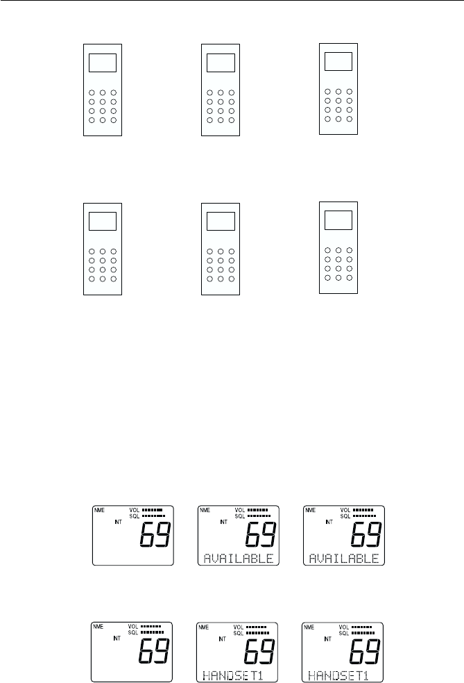
3-29
Operations
5) Handset 1 is Off-Hook while another Handset is Off-Hook
Handset 1 Handset 2 Handset 3
OFF-Hook On-Hook OFF-Hook
Operation possible Operation disabled Operation limited
6) All Handsets are Off-Hook
Handset 1 Handset 2 Handset 3
OFF-Hook OFF-Hook OFF-Hook
Operation possible Operation limited Operation disabled
In cases 5 and 6 above, limited operation means the handset can talk on
the Intercom, adjust the sound volume, and make a Distress Call.
Handset Display:
The dot matrix display indicates the handset's rank. If Handset 1 has
priority, for example, the message AVAILABLE is displayed on the LCD of
Handset 1 while HANDSET 1 is displayed on the LCD of the other
handsets.
1) If all Handsets are On-Hook
Handset1 Handset 2 Handset 3
2) If only Handset 1 is Off-Hook
Handset 1 Handset 2 Handset 3

3-30 Operations
3) If only Handset 2 is Off-Hook.
Handset 1 Handset 2 Handset 3
3.5.243.5.24
3.5.243.5.24
3.5.24 NMEA OperationNMEA Operation
NMEA OperationNMEA Operation
NMEA Operation
The RAY230/RAY230/E can receive valid position and time information
from an external device from an NMEA signal. This information can be
broadcast during a DSC call. See section 3.5.26.
Operation at Power Up
At power up, the SeaTalk line is monitored for 1 minute. If a signal is
detected, the NMEA line is not monitored. If no signal is detected on the
SeaTalk line, the radio is put in monitor mode and switches over to the
NMEA line. If no NMEA data is input during the 1 minute monitor time at
power up, all the position fields are set to 9’s and the time fields are set to
8’s. An error alert tone sounds to urge manual entry (see Section 3.5.30.3.2)
and the NMEA indicator disappears.
Validating NMEA Data
When an NMEA signal is received, it must be determined whether the data
is valid. Receivable commands are limited to the position commands of
GGA, GLL, RMC, and RMA and to the status commands of RMC, APB,
GLL, and APA. If valid, the data is input and the NMEA indicator is
displayed on the LCD.
Operation with Input Data Error
If position data becomes invalid or is not detected, the NMEA indicator
flashes and an alert tone of 1-minute duration is sounded at 4 hour intervals
to urge manual input of positional data. If no manual input was made
during the prior 23.5 hours, all the position data is set to 9’s and all the time
data to 8’s.

3-31
Operations
3.5.25 SeaTalk Operation3.5.25 SeaTalk Operation
3.5.25 SeaTalk Operation3.5.25 SeaTalk Operation
3.5.25 SeaTalk Operation
The RAY230/RAY230E can receive SeaTalk position and time information
from any SeaTalk capable device. As with NMEA data, if the position
information becomes invalid or is not present, you will be prompted to
manually input position data.
3.5.26 Digital Selective Calling (DSC)3.5.26 Digital Selective Calling (DSC)
3.5.26 Digital Selective Calling (DSC)3.5.26 Digital Selective Calling (DSC)
3.5.26 Digital Selective Calling (DSC)
Digital Selective Calling (DSC) operation includes the following:
1. Transmitting/Receiving an Individual Call
(including semi-automatic ship to shore phone calls)
2. Receiving a Group Call
3. Transmitting/Receiving an All Ships Call
4. Transmitting/Receiving a Distress Call
With the RAY230 and RAY230E, DSC transmission and reception occurs
on Channel 70. Actually, the RAY230/E has a separate receiver exclusively
for Channel 70 so that even if receiving under normal operation, the unit
can quickly switch over to Channel 70 upon receiving a DSC signal. When
the DSC signal is received, the unit performs the corresponding operation.
If the radio is transmitting, however, receiving on Channel 70 is disabled.
Transmitting an Individual Call
Press the IND key to initiate the call data setup operation. After setting the
call data, press the PTT switch to send the call at a transmission output of
1W. The following describes the two types of calling operations: Individual
Ship's (ship-to-ship) Call and Shore station (ship-to-shore) Call.
3.5.26.1 Individual Call to another Ship3.5.26.1 Individual Call to another Ship
3.5.26.1 Individual Call to another Ship3.5.26.1 Individual Call to another Ship
3.5.26.1 Individual Call to another Ship
(Ship-to-Ship)(Ship-to-Ship)
(Ship-to-Ship)(Ship-to-Ship)
(Ship-to-Ship)
To call another ship, you must select the Working Channel and a specific
MMSI number. The MMSI number is selected either manually or from a
Phonebook list of preprogrammed numbers specified using the MENU
function. To cancel the call, press and hold the CLR key for 4 seconds.
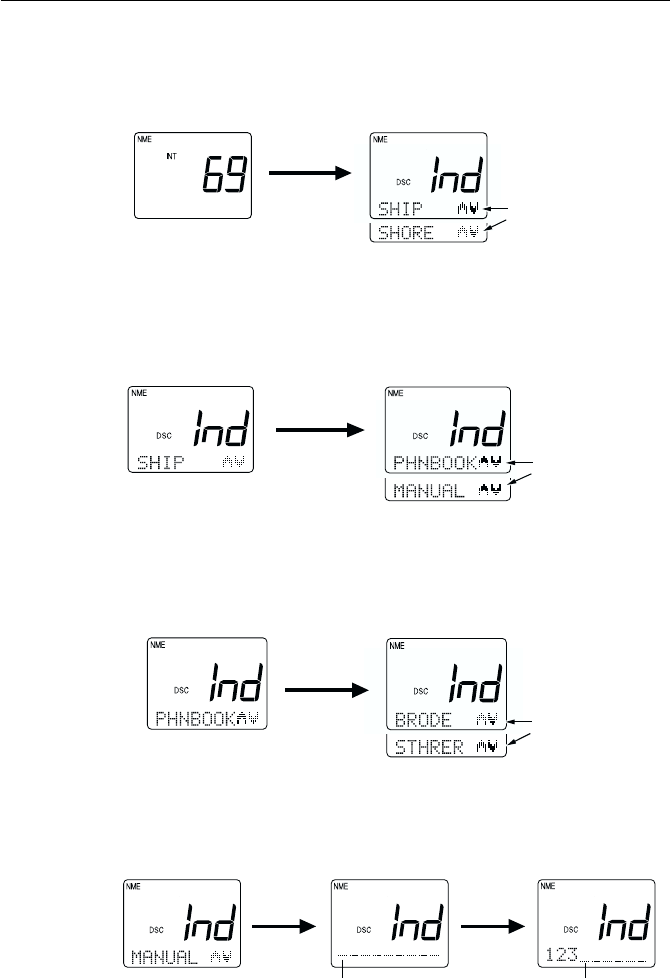
3-32 Operations
ENT
Use SQ UP/DOWN key
to scroll through list of
MMSI nos./nicknames
To Make an Individual Call to Ship (ship-to-ship):
1) Press the INDV key. Ind appears on the 7-segment display and the DSC
indicator is displayed.
Pressing the SQ UP/DOWN key alternates between SHIP and SHORE.
2) Select SHIP and press the ENT key.
3) Scroll with the SQ UP/DOWN keys to select the method for inputting
the MMSI number, either from the Phonebook or manually. Press ENT.
4) Select the MMSI number.
BY PHONEBOOK:
Scroll with the SQ UP/DOWN keys, select the name associated with
the desired MMSI number, and press the ENT key. If the MMSI number
is not listed in phonebook, the display reverts to manual input.
OR
BY MANUAL INPUT:
Input the 9-digit MMSI number with the numeric keypad, then press
the ENT key.
ENT
Changed by pressing
SQ UP/DOWN key
ENT
numeric
keypad
Flashing Flashing
INDV
Alternates with each click of
the SQ UP/DOWN key
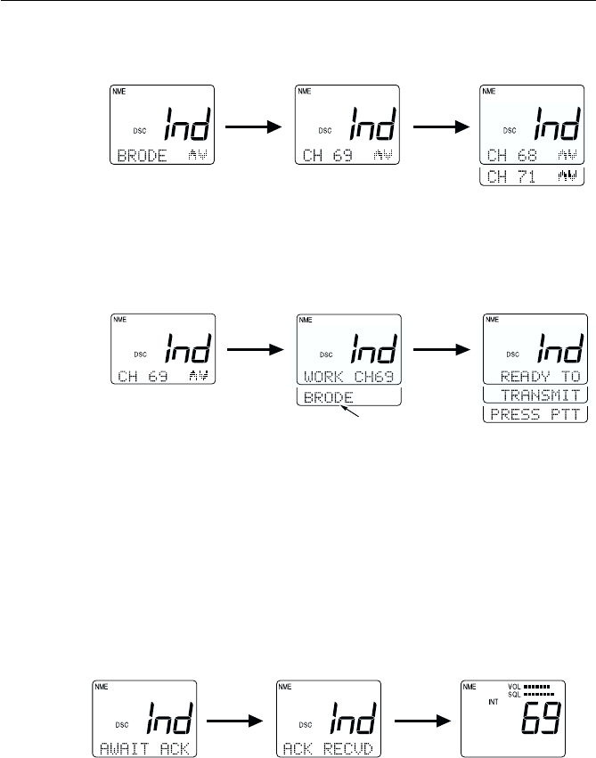
3-33
Operations
5) Specify the Working Channel with the SQ UP/DOWN keys and press
the ENT key.
6) Press the ENT key again. A prompt appears on the display instructing
you to press the PTT switch.
7) Press PTT to transmit. If PTT is not pressed within 15 seconds of the
prompt appearing, operation returns to the state before the call.
Note: Only simplex channels (those channels that transmit and receive
on the same frequency) can be selected for ship to ship Individual Calls.
Pressing the SQ UP/DOWN will scroll you through the simplex channels
usable for this operation.
Response
If a response is received after pressing the PTT switch, a receive-
confirmation message is displayed. After 5 seconds have elapsed, the
channel is changed to a communication channel and the Individual Ships
Call is completed.
If no response is received for 3 minutes after pressing the PTT switch, a
prompt to press the PTT switch appears once more. After 15 seconds
elapses without pressing the PTT switch following the prompt, operation
returns to the state before the call.
ACK 5 sec
ENT ENT
MMSI number or
nickname is displayed
ENT
SQ UP/
DOWN
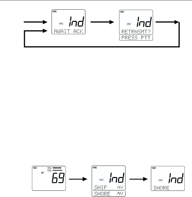
3-34 Operations
3.5.26.2 Individual Call to Shore Station3.5.26.2 Individual Call to Shore Station
3.5.26.2 Individual Call to Shore Station3.5.26.2 Individual Call to Shore Station
3.5.26.2 Individual Call to Shore Station
(Ship-to-Shore)(Ship-to-Shore)
(Ship-to-Shore)(Ship-to-Shore)
(Ship-to-Shore)
To call a shore station, you must select the specific MMSI number and, if
desired, the telephone number. The MMSI number must be selected from
a Phonebook list of preprogrammed numbers specified using the MENU
function. The telephone number can be entered manually or preset with
the MMSI number in Ship to Shore setup. Channel 16 is automatically
assigned for communications.
To cancel the call, press and hold the CLR key for 4 seconds.
To make an Individual Call to Shore Station (ship-to-shore):
1) Press the INDV key. The Ind appears on the 7-segment display and the
DSC indicator is displayed.
Pressing the SQ UP/DOWN key alternates between SHIP and SHORE.
2) Select SHORE and press the ENT key.
3) Scroll with the SQ UP/DOWN keys to select the method for inputting
the MMSI number, either from the phonebook or manually. Press ENT
to input your selection.
4) Select the name by MMSI number from the phonebook by scrolling
with the SQL UP/DOWN keys, and pressing the ENT key.
INDV ENT
Alternates with each
click of SQ UP/DOWN
After pressing ENT, the
indication switches to:
PHNBOOK, MANUAL
NO ACK
Scrolls every 15 sec
3 min
PTT PTT
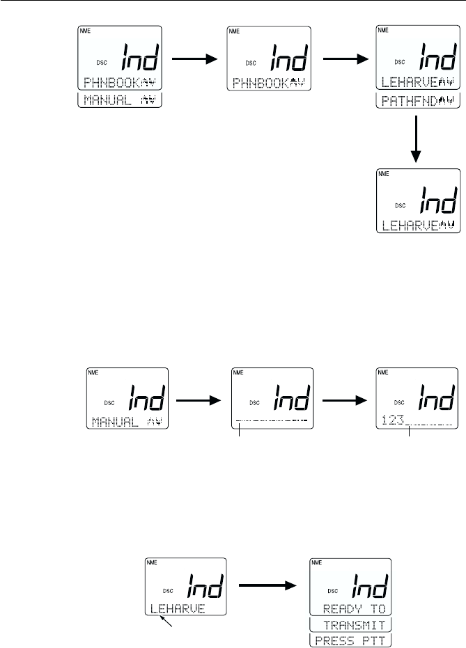
3-35
Operations
OR
Manually input the phone number with the numeric keypad, then press
the ENT key.
5) Press ENT again. A prompt appears on the display instructing you to
press the PTT switch.
6) Press PTT to transmit. If PTT is not pressed within 15 seconds of the
prompt appearing, operation returns to the state before the call.
ENT
With manual input, MMSI
number would be displayed
ENT ENT
ENT
Use SQ UP/DOWN key to scroll through
list of MMSI nicknames. Press ENT when
desired selection is displayed
ENT
numeric
keypad
Flashing Flashing
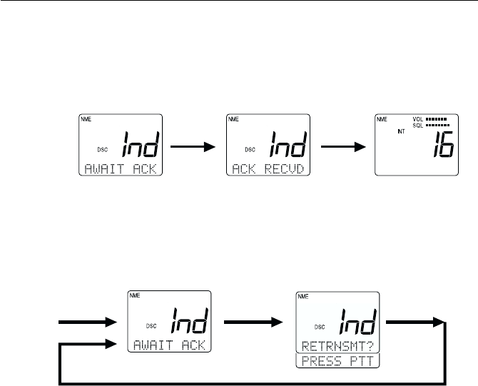
3-36 Operations
Response
If a response is received after pressing the PTT switch, a receive-
confirmation message is displayed. After 5 seconds have elapsed, the
channel is shifted to a communication channel and the Individual Call is
completed.
If no response is received for 3 minutes after pressing the PTT switch, a
prompt to press the PTT switch appears once more. If the PTT switch is
not pressed within 15 seconds after the prompt appears, operation returns
to the state before the call.
3.5.26.3 Receiving an Individual Call3.5.26.3 Receiving an Individual Call
3.5.26.3 Receiving an Individual Call3.5.26.3 Receiving an Individual Call
3.5.26.3 Receiving an Individual Call
When an Individual Call is received, the DSC indicator flashes, INd appears
on the 7-segment display, and the DSC Received Alert is sounded. On the
dot matrix display appears the message RECEIVED IND CALL along with
a prompt to press ENT to accept or CLR to log the call. If the MMSI
number exists in the list, the associated name is displayed. If no match is
found, the actual numeric value of the MMSI is displayed.
Until either the ENT key or the CLR key are pressed, the prompt is flashed
at 1-second intervals and is accompanied by an alarm for up to 3 minutes.
If neither ENT nor CLR are pressed during these 3 minutes, the radio
reverts to the operation mode before receiving the Individual Call. The
DSC indicator continues to be flashed on the LCD display until the contents
of the log files can be confirmed.
NO ACK
Scrolls every 15 sec
3 min
PTT PTT
ACK 5 sec
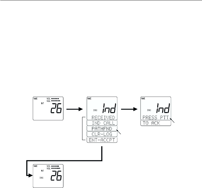
3-37
Operations
If ENT is pressed, the alarm is turned off, and a new prompt appears on the
display, instructing you to press the PTT switch. Press PTT to transmit an
acknowledgement (ACK). If PTT is not pressed within 5 seconds of the
prompt appearing, the transmission is done automatically. Pressing the
PTT switch causes the channel to change to the communication channel.
If the CLR key is pressed, the alarm is turned off and the displays are
cleared and the received contents are stored in the Log File. The radio then
reverts to the operation mode before receiving the Individual Call. DSC
will continue flashing to indicate there is an unread call in the log.
3.5.26.4 Receiving a Group Call3.5.26.4 Receiving a Group Call
3.5.26.4 Receiving a Group Call3.5.26.4 Receiving a Group Call
3.5.26.4 Receiving a Group Call
When a Group Call is received, the DSC indicator flashes, INd appears on
the 7-segment display, and the DSC Received Alert is sounded. On the dot
matrix display appears the message RECEIVED IND CALL, along with a
prompt to press ENT to accept or CLR to log the call. If the MMSI number
exists in the list, the associated name is displayed. If no match is found, the
actual numeric value of the MMSI is displayed.
Until either the ENT key or the CLR key are pressed, the prompt is flashed
at 1-second intervals and is accompanied by an alarm for up to 3 minutes.
If neither ENT nor CLR are pressed during these 3 minutes, the radio
reverts to the operation mode before receiving the Group Call. The DSC
indicator continues to be flashed on the LCD display until the contents of
the log files can be confirmed.
Scrolls
If the CLR key is pressed
Receiving ENT
Automatic transmission is
done if MMSI No. is displayed
but the No. is not listed
After no operation
for 5 seconds
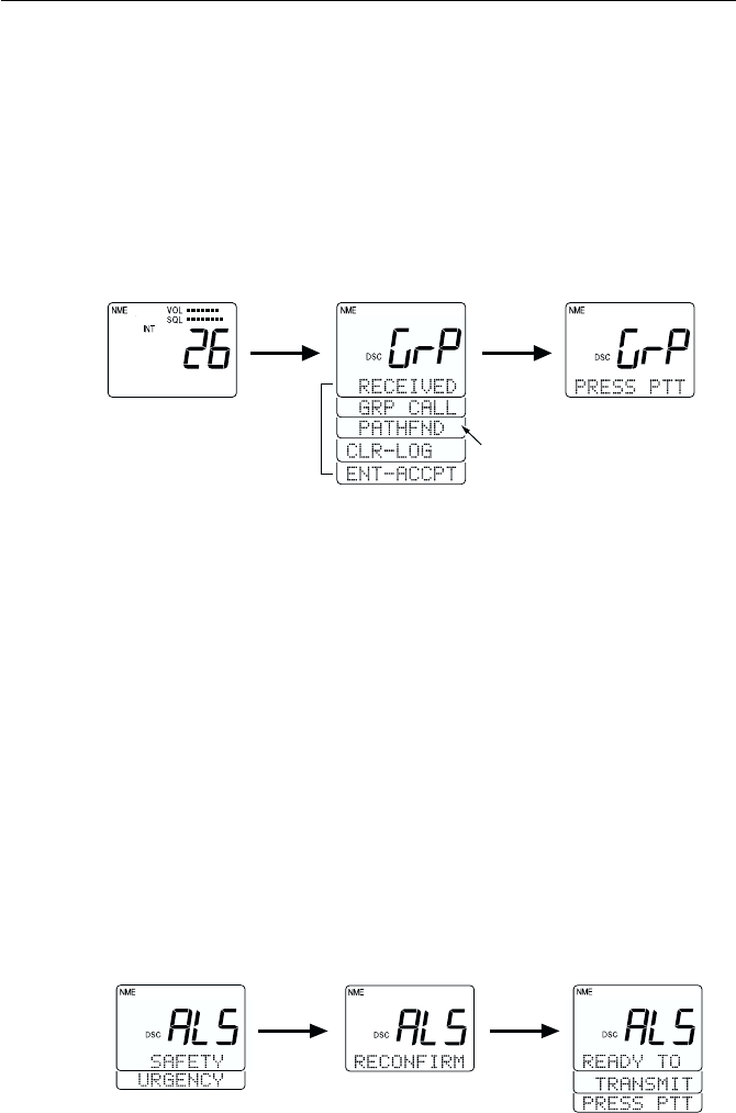
3-38 Operations
If ENT is pressed, the alarm is turned off, and a new prompt appears on the
display, instructing you to press the PTT switch. Press PTT to transmit. If
PTT is not pressed within 5 seconds of the prompt appearing, the
transmission is done automatically. Pressing the PTT switch causes the
channel to change to the communication channel.
If the CLR key is pressed, the alarm is turned off, the displays are cleared,
and the received contents are stored in the Log File. The radio then reverts
to the operation mode before receiving the Individual Call. DSC will
continue flashing to indicate there is an unread call in the log.
3.5.26.5 Transmitting an All Ships Call3.5.26.5 Transmitting an All Ships Call
3.5.26.5 Transmitting an All Ships Call3.5.26.5 Transmitting an All Ships Call
3.5.26.5 Transmitting an All Ships Call
The All Ships Call is classified in two categories: Safety Call and Urgency
Call.
To send an All Ships Call
1) Press the ALL SHIP key. The DSC indicator is displayed, and the
message SAFETY appears on the dot matrix display.
2) Press the SQ UP/DOWN key. The message URGENCY now appears on
the dot matrix display.
3) Make you selection between SAFETY or URGENCY and press the
ENT key to submit. The prompt RECONFIRM is displayed.
4) Press the ENT key to confirm. A prompt appears on the display,
instructing you to press the PTT switch.
5) Press PTT to transmit the call.
The All Ships Call is made on Channel 16. The transmission power is 1W
for a SAFETY Call and 25W for an URGENCY Call.
ENT ENT
Alternate by pressing the
SQ UP/DOWN key
Receiving ENT
Automatic transmission is
done if MMSI No. is not listed.
Scrolling every 1 sec
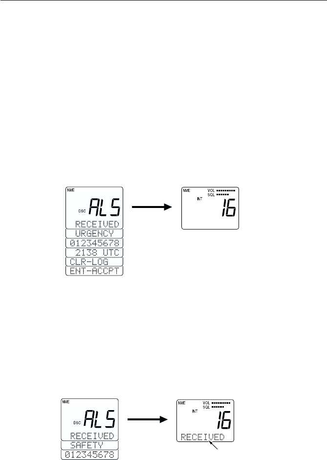
3-39
Operations
3.5.26.6 Receiving an All Ships Call3.5.26.6 Receiving an All Ships Call
3.5.26.6 Receiving an All Ships Call3.5.26.6 Receiving an All Ships Call
3.5.26.6 Receiving an All Ships Call
When receiving an All Ships Call, the unit's manner of response depends
on the type of call received.
When an URGENCY call is received, the DSC Distress alert is sounded.
The LCD displays a message that an URGENCY call is being received,
along with the sender's MMSI number, and a prompt to press ENT to
accept or CLR to log the call. The DSC Distress alert and the displayed
message continue until either ENT or CLR is pressed. If ENT is pressed,
the radio switches to Channel 16 in 25W mode and the contents of the
communication are stored in EEPROM. If CLR is pressed, the radio reverts
to the mode before receiving the URGENCY Call and the contents are
stored in EEPROM.
When a SAFETY call is received, the DSC Received alert is sounded. The
LCD displays a message that an SAFETY call is being received, along with
the sender's MMSI number, and a prompt to press ENT to accept or CLR to
log the call. The DSC Received alert and the displayed message continue
until either ENT or CLR is pressed. If ENT is pressed, the radio switches to
Channel 16 in 25W mode and the contents of the communication are stored
in memory. If CLR is pressed, the radio reverts to the mode before receiving
the SAFETY Call and the contents are stored in memory.
If CLR is pressed, the radio
reverts to the mode before
receiving the Safety Call
ENT
"DSC Received"
Alert sounds
ENT
If CLR is pressed, the radio
reverts to the mode before
receiving Urgency Call
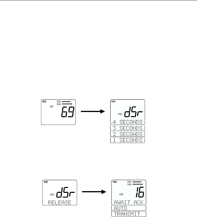
3-40 Operations
3.5.26.7 Transmitting a Distress Call3.5.26.7 Transmitting a Distress Call
3.5.26.7 Transmitting a Distress Call3.5.26.7 Transmitting a Distress Call
3.5.26.7 Transmitting a Distress Call
Two types of Distress Calls can be made: one that specifies the type of
distress and one that does not.
Unspecified Distress Call
To make a Distress Call without specifying type of distress:
1) Open the door labeled DISTRESS on the back of the handset and press
and hold the DISTRESS key. The message dSr is displayed on the 7-
segment LCD and the DSC indicator is displayed. On the dot matrix
display, a countdown message appears prompting you to hold the
DISTRESS key for 4 seconds.
2) After the countdown has completed, release the DISTRESS key. The
unit is switched to channel 16, displays the message AWAIT ACK,
and monitors channel 70 for an acknowledgement.
The unit retransmits the DISTRESS call at random intervals of 3.5 to 4.5
minutes, until a response is received or the call is manually cancelled.
To cancel the DISTRESS call, press the CLR key and hold for 3 seconds.
The call is cancelled and the unit returns to the state before the call.
release
DISTRESS
press
DISTRESS
Countdown starts 1 second after pressing
DISTRESS key. The types of DISTRESS
can be selected by releasing the key
before the Countdown is completed.
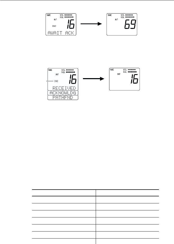
3-41
Operations
When a response is received, the DSC indicator flashes and the DSC
Distress alert is sounded. The LCD scrolls a message that the DISTRESS
has been acknowledged, along with the sending station's MMSI number.
The message and alert are repeated until the CLR key is pressed.
When the CLR key is pressed, the unit exits the DSC mode continues
monitoring Channel 16 on high power.
Regardless of the handset state, the DSC Distress alert is sounded at
maximum volume on the external speaker.
Specified Distress Call
You can assign one of eleven distress types to the call to provide the
potential rescuing station additional information if time and circumstances
permit. The Nature of the distress call can be selected using the DISTRESS
key as outlined below or in the system MENU as outlined in Section
3.5.30.3.1. Below are the messages and their meaning:
MessageMessage
MessageMessage
Message MeaningMeaning
MeaningMeaning
Meaning MessageMessage
MessageMessage
Message MeaningMeaning
MeaningMeaning
Meaning
FIRE fire ADRIFT drifting
FLOODNG flooding UNDESIG undesignated
COLLISN collision ABNDSHP abandoning ship
AGROUND run aground PIRACY piracy
LISTING listing MANONBD man overboard
SINKING sinking
CLR
Flashing
press and hold
CLR for 3
seconds
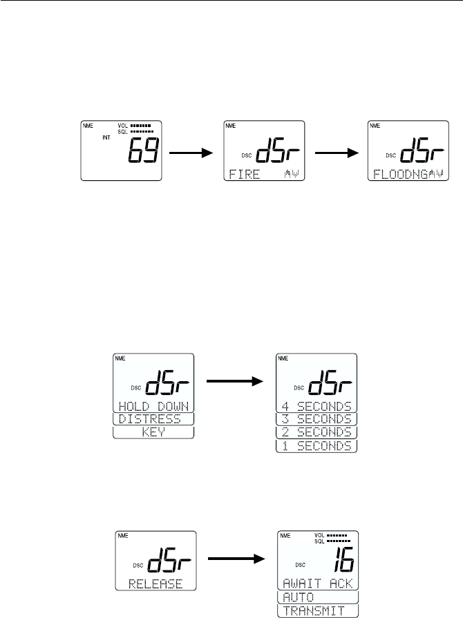
3-42 Operations
To make a Distress Call specifying the type of distress:
1) Open the door labeled DISTRESS on the back of the handset and press
and release the DISTRESS key on the back of the handset. The message
dSr is displayed on the 7-segment LCD and the DSC indicator is
displayed. On the dot matrix display, the message FIRE appears.
2) If FIRE is the message you wish to attach, press the ENT key.
OR
If FIRE is not the message you wish to attach, scroll through the list
with the SQ UP/DOWN keys. When the appropriate message is
displayed, press the ENT key.
On the dot matrix display, a message appears prompting you to hold
the DISTRESS key for 4 seconds. A countdown message is displayed.
3) Continue to press and hold the DISTRESS key. After 4 seconds have
elapsed, the message RELEASE appears, prompting you to release the
key.
4) When the prompt appears, release the DISTRESS key. The unit is
switched to Channel 16, displays the message AWAIT ACK, and
monitors channel 70 for an acknowledgement.
hold
DISTRESS
press and
release
DISTRESS
SQ UP/
DOWN
release
DISTRESS
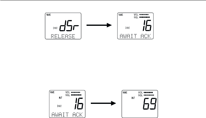
3-43
Operations
The unit retransmits the DISTRESS call at random intervals of 3.5 to 4.5
minutes, until a response is received or the call is manually cancelled.
To cancel the DISTRESS call, press the CLR key and hold for 3 seconds.
The call is cancelled and the unit returns to the state before the call.
When a response is received, the DSC indicator flashes and the DSC
Distress alert is sounded. The LCD scrolls a message that the DISTRESS
has been acknowledged, along with the sending station's MMSI number.
The message and alert are repeated until the CLR key is pressed.
When the CLR key is pressed, the unit exits the DSC mode continues
monitoring Channel 16 on high power.
Regardless of the handset state, the DSC Distress alert is sounded at
maximum volume on the external speaker.
press and hold
CLR 3 seconds
DISTRESS OFF
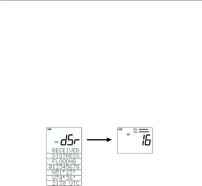
3-44 Operations
3.5.26.8 Receiving a Distress Call3.5.26.8 Receiving a Distress Call
3.5.26.8 Receiving a Distress Call3.5.26.8 Receiving a Distress Call
3.5.26.8 Receiving a Distress Call
When a Distress call is received, the DSC indicator flashes, the message
DSr is placed on the 7-segment display, and the DSC Distress alert is
sounded. On the dot matrix display are scrolled RECEIVED, DISTRESS,
the type of distress, the MMSI number, the transmitting time, the latitude,
and longitude of the transmitting station.
The DSC Distress Alert and the displayed message continue until either
ENT or CLR is pressed. When ENT or CLR is pressed, the radio switches
to channel 16 in 25 W mode and the contents of the communication are
stored in memory.
Five seconds after receiving the Distress Call, operation switches to Channel
16. Pressing the CLR key turns off the alert and clears the dot matrix display.
The received contents are stored in the Log File.
after 5 secs

3-45
Operations
3.5.27 ATIS Operation (RAY230E only)3.5.27 ATIS Operation (RAY230E only)
3.5.27 ATIS Operation (RAY230E only)3.5.27 ATIS Operation (RAY230E only)
3.5.27 ATIS Operation (RAY230E only)
The RAY230E European model comes equipped with ATIS capability for
inland waterway requirements in Europe. Your dealer or distributor must
first activate the ATIS feature before it can be utilized. Once activated, this
feature can be enabled or disabled in the system MENU so that the RAY230E
can be used in open water or inland waterways. With ATIS enabled, each
time the PTT switch is pressed your station ID is transmitted.
3.5.28 Alert Operation3.5.28 Alert Operation
3.5.28 Alert Operation3.5.28 Alert Operation
3.5.28 Alert Operation
This function emits various sounds to attract the operator's attention for
confirming a key operation, warning of an erroneous key operation, or
informing of a specific state. The different types of alert sounds are
described below.
1) Key Click
This sound is made when a handset key is pressed. In the On-Hook
state the sound emits from the external speaker; in the Off-Hook state
the sound emits from the handset speaker. The key click volume level
is determined by the sound volume setting.
2) Operation Error Alert
This alert sounds when an erroneous key operation is made. In the On-
Hook state the sound emits from the external speaker; in the Off-Hook
state the sound emits from the handset speaker. The alert tone volume
level is determined by the sound volume setting.
3) DSC Distress Alert
This sound is made when receiving a distress call in the DSC receiving
mode, receiving an acknowledgment to a transmitted distress signal,
or an Urgency signal to All Ships. The alert is output from the external
speaker at the maximum sound volume, regardless of the handset volume
setting.
4) DSC Received Alert
This sound is made when receiving an Individual Ships Call in DSC
receiving mode, a Group Ships Call, or a Safety call to All Ships. In this
case the sound is made from the external speaker. The alert is sounded
at maximum volume regardless of the volume setting.

3-46 Operations
5) DSC Transmission Alert
This sound is emitted from the external speaker to notify that the DSC
code is being sent after transmission is completed. The alert is sounded
at maximum volume regardless of the volume setting.
6) Weather Alert
This sound is made at the detection of a NOAA Weather Alert. The
alert is sounded from the external speaker at maximum volume regardless
of the volume setting or handset state.
7) Cellular Phone Call Sound
This sound is emitted from the external speaker when a call is received
by the optional cellular fixed wireless terminal, if installed. The call
volume level is determined by the sound volume setting.
8) Intercom Call Sound 1
This sound is made upon receiving a call using the Intercom function,
when selected through the Menu operation. If Off-Hook, the sound
emits from the handset; if On-Hook, the sound emits from the external
speaker at a low volume. The call volume level is determined by the
sound volume setting.
9) Intercom Call Sound 2
This sound is made upon receiving a call using the Intercom function,
when selected through the Menu operation. If Off-Hook, the sound
emits from the handset; if On-Hook, the sound emits from the external
speaker at a low volume. The call volume level is determined by the
sound volume setting.
10) Intercom Call Sound 3
This sound is made upon receiving a call using the Intercom function,
when selected through the Menu operation. If Off-Hook, the sound
emits from the handset; if On-Hook, the sound emits from the external
speaker at a low volume. The call volume level is determined by the
sound volume setting.

3-47
Operations
11) Intercom Call Sound 4
This sound is made upon receiving a call using the Intercom function,
when selected through the Menu operation. If Off-Hook, the sound
emits from the handset; if On-Hook, the sound emits from the external
speaker at a low volume. The call volume level is determined by the
sound volume setting.
12) Siren 1 ("Hi-Lo" Sound)
Select this sound option under Siren in the Menu operation. While in
Fog/Siren mode, pressing and releasing the PTT switch emits a
continuous "Hi-Lo" sound from the Hailer Horn speaker at maximum
volume. Pressing PTT again, the Hi-Lo sound stops.
13) Siren 2 (Siren Sound)
Select this sound option under Siren in the Menu operation. While in
Fog/Siren mode, pressing and releasing the PTT switch emits a
continuous siren sound from the Hailer Horn speaker at maximum
volume. Pressing PTT again, the siren sound stops.
14) Siren 3 (Whelp Sound)
Select this sound option under Fog Siren 1 in the Menu operation.
While in Fog/Siren mode, pressing and holding the PTT switch emits a
whooping or “whelp” sound from the Hailer Horn speaker at maximum
volume. When PTT is released, the whooping sound stops.
15) Siren 4 (Fog Horn)
Select this sound option under Fog Siren 1 in the Menu operation.
While in Fog/Siren mode, pressing and holding the PTT switch emits
an air horn sound from the Hailer Horn speaker at maximum volume.
When PTT is released, the air horn stops.
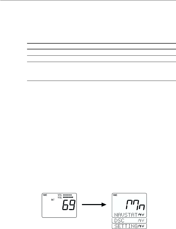
3-48 Operations
3.5.30.1 Selecting the Menu Operation3.5.30.1 Selecting the Menu Operation
3.5.30.1 Selecting the Menu Operation3.5.30.1 Selecting the Menu Operation
3.5.30.1 Selecting the Menu Operation
To initiate the Menu function:
1) Press the FUNC key followed by the MENU key. The indication Mn is
shown on the 7-segment display and NAVSTAT is shown on the dot
matrix display.
2) To scroll through these first level menu items, press the SQ UP/DOWN
key. The indicators alternate between NAVSTAT, DSC, and SETTING.
3) Select the desired operation and press the ENT key to enter that
particular menu item.
To exit the Menu operation, press and hold the CLR key for 3 seconds.
FUNC + MENU
FunctionFunction
FunctionFunction
Function PurposePurpose
PurposePurpose
Purpose
1. NAVSTA Indicates the information input from NMEA or SeaTalk.
2. DSC To register/modify various settings related to DSC.
3. SETTING To register the names of stations for Intercom mode, to
set the tone of the Fog Siren, and to set the operation
mode of ATIS (for RAY230E).
3.5.3 Menu Operation3.5.3 Menu Operation
3.5.3 Menu Operation3.5.3 Menu Operation
3.5.3 Menu Operation
The menu operation is used for making various settings and confirming
the current state. The operation is roughly divided in three functions as
follows:
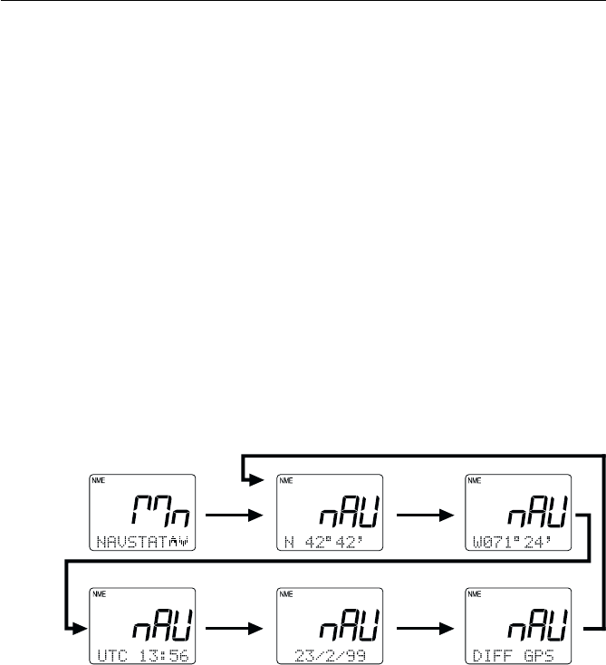
3-49
Operations
3.5.30.2 NAVSTAT Operation3.5.30.2 NAVSTAT Operation
3.5.30.2 NAVSTAT Operation3.5.30.2 NAVSTAT Operation
3.5.30.2 NAVSTAT Operation
This operation indicates on the LCD display the position information that
has been input through NMEA or SeaTalk.
1) Press the FUNC key followed by the MENU key to initiate the Menu
operation.
2) Select NAVSTAT and press the ENT key. Scroll through the following
five items with the SQ UP/DOWN key, or wait as they are automatically
displayed at 3-second intervals in the following order:
1. Latitude 4. UTC Data (Y/M/D)
2. Longitude 5. Position source (GPS, LORAN, etc.)
3. UTC Time
This data is for viewing only and can not be altered. Manual position entry
is done in the DSC menu as outlined in Section 3.5.30.3.2
3 sec or
SQ UP/DOWN
3 sec or
SQ UP/DOWN
after 3 seconds elapse or pressing SQ UP/DOWN
3 sec or
SQ UP/DOWN
3 sec or
SQ UP/DOWN
To return to the main menu screen, again press FUNC followed by MENU.
To exit the Menu operation, press and hold the CLR key for 3 seconds.
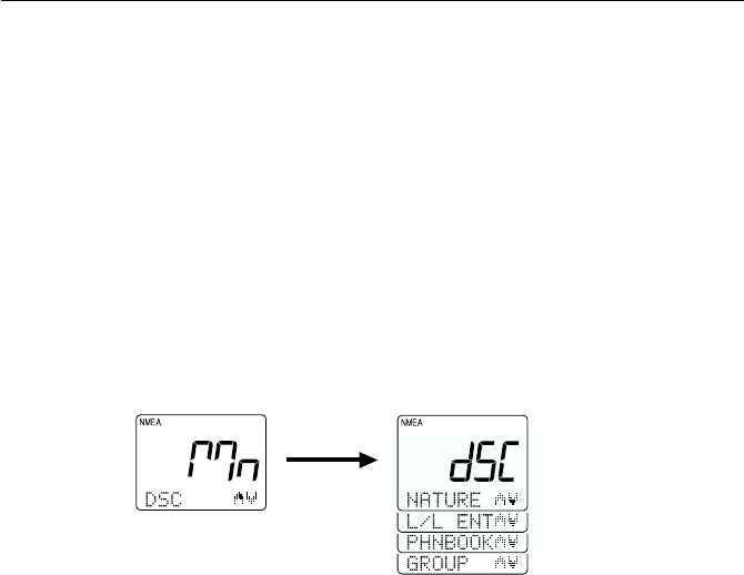
3-50 Operations
3.5.30.3 DSC Operation3.5.30.3 DSC Operation
3.5.30.3 DSC Operation3.5.30.3 DSC Operation
3.5.30.3 DSC Operation
DSC operation includes the manual entry of latitude/longitude, listing of
other ship’s MMSI numbers for ship-to-ship and ship-to-shore
communications, and listing of Group MMSI number.
1) Press the FUNC key followed by the MENU key to initiate the Menu
operation.
2) Select NAVSTAT and press the ENT key. The 7-segment display shows
dSC and the dot matrix display shows L/L ENT.
The DSC Main Menu is made up of NATURE, L/L ENT, PHNBOOK, and
GROUP submenus.
SQ UP/DOWN
3) Press the SQ UP/DOWN key until the desired operation is
displayed:
NATURE Select type of Distress Call
L/L ENT Manual entry of latitude/longitude
PHNBOOK Listing of MMSI number
GROUP Listing of Group MMSI number
4) Press the ENT key to submit.
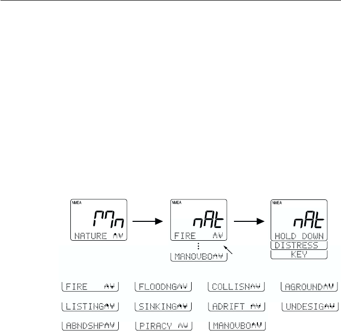
3-51
Operations
SQ UP/
DOWN ENT
Selections
shown
below:
3.5.30.3.1 Selecting Distress Call Type (NATURE)3.5.30.3.1 Selecting Distress Call Type (NATURE)
3.5.30.3.1 Selecting Distress Call Type (NATURE)3.5.30.3.1 Selecting Distress Call Type (NATURE)
3.5.30.3.1 Selecting Distress Call Type (NATURE)
This menu item is used to select the nature of a distress call before the call
is sent. The selected information will be sent along with the distress call.
To select the nature of the distress that will be included with the call:
1) As described in section 3.5.30.3 DSC Operation above, select the DSC
operation NATURE.
2) Press the ENT key to initiate the process. The 7-segment display shows
nAt and the dot matrix display shows FIRE.
3) Use the SQ UP/DOWN key to select the type of distress.
3) After selecting the desired distress type, press ENT. You are prompted
to press the DISTRESS key.
5) To send the distress call at this time, press and hold the DISTRESS
button. Follow the instructions on the display or the steps described
in Section 3.5.26.7.
4) To cancel the distress call, press and hold CLR for 3 seconds.

3-52 Operations
3) The subject items can be changed in the following order. Numeric values
that can be changed are flashing:
1. Degrees of lat at tens place 8. Minutes of lon at tens place
2. Degrees of lat at unit's place 9. Minutes of lon at unit's place
3. Minutes of lat at tens place 10. Hours of UTC at tens place
4. Minutes of lat at unit's place 11. Hours of UTC at unit's place
5. Degrees of lon at hundreds 12. Minutes of UTC at tens place
6. Degrees of lon at tens place 13. Minutes of UTC at units place
7. Degrees of lon at unit's place
4) After changing the subject item, the display scrolls from latitude to
longitude to UTC. To submit the change of the position data as shown
in the display, press the ENT key. The unit exits Menu mode and returns
to normal operation.
To exit the Menu operation, press and hold the CLR key for 3 seconds.
The following illustration shows an example of the operation:
KeysKeys
KeysKeys
Keys ActionAction
ActionAction
Action
0 - 9 keys Changes the flashing numeric value (see step 3), then
advances to the next digit's place.
ENT key Advances the (flashing) subject item to the next one
without changing the numeric value. Advances from
Latitude, to Longitude, to UTC.
CLR key Returns to the previous subject item.
SQ UP/ For Latitude, alternates between N and S.
DOWN key For Longitude, alternates between E and W.
For UTC, no effect.
3.5.30.3.2 Manual Entry of Lat/Longitude (L/L ENT)3.5.30.3.2 Manual Entry of Lat/Longitude (L/L ENT)
3.5.30.3.2 Manual Entry of Lat/Longitude (L/L ENT)3.5.30.3.2 Manual Entry of Lat/Longitude (L/L ENT)
3.5.30.3.2 Manual Entry of Lat/Longitude (L/L ENT)
This operation is used to manually enter the latitude/longitude and UTC
time when normal entry of the position information has been disabled.
1) As described in section 3.5.30.3 DSC Operation above, select the DSC
operation L/L ENT. The 7-segment display shows L L, while the dot
matrix display shows the latest latitude data.
2) Press one of the following keys to initiate the corresponding
operation:
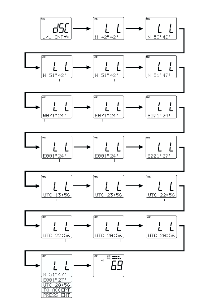
3-53
Operations
press ENT
press ENT
press 5
press 7
press SQ
UP/DOWN press ENT
press 7press ENT
press 2 press ENT
press ENT
Flashing Flashing
Flashing
Flashing Flashing Flashing
Flashing Flashing
FlashingFlashing Flashing
Flashing Flashing
Flashing
press ENT
press ENT
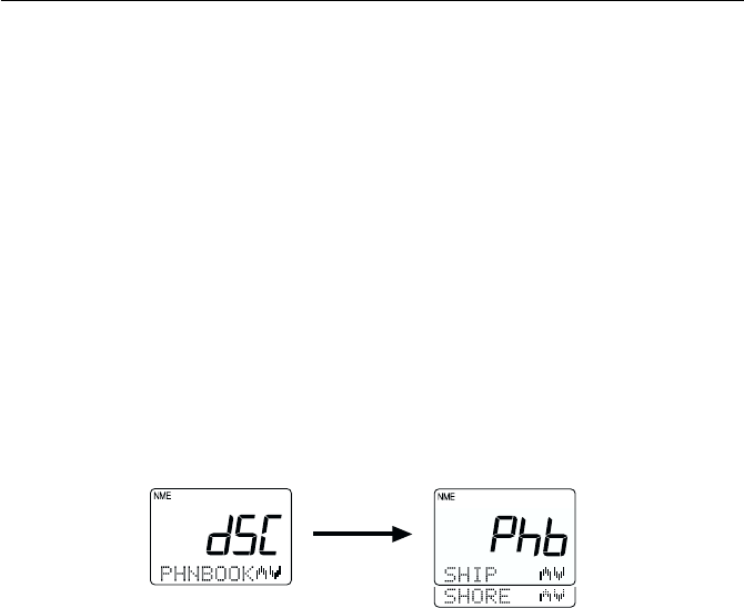
3-54 Operations
3.5.30.3.3 Modifying the MMSI Number List3.5.30.3.3 Modifying the MMSI Number List
3.5.30.3.3 Modifying the MMSI Number List3.5.30.3.3 Modifying the MMSI Number List
3.5.30.3.3 Modifying the MMSI Number List
(PHNBOOK)(PHNBOOK)
(PHNBOOK)(PHNBOOK)
(PHNBOOK)
This operation is used to modify the "phonebook" lists of MMSI numbers
used for DSC Individual Calls. Two lists are available: one for Ship stations
and one for Shore stations. Each list enables you to register a maximum of
20 stations. The list for the Ship station allows you to register the MMSI
number and nickname of the station, while the list for the Shore station
additionally enables you to register the telephone number for semi-
automatic ship-to-shore calling.
1) As described in section 3.5.30.3 DSC Operation above, select the DSC
operation PHNBOOK.
2) Press the ENT key to initiate the process. The 7-segment display shows
Phb and the dot matrix display shows SHIP.
3) Use the SQ UP/DOWN key to select between SHIP or SHORE.
4) Press the ENT key to turn to submit your selection.
Modifying the List of Ship Stations
In this operation, a ship is registered (added) to or deleted from the
phonebook list for ship stations.
1) When SHIP is displayed, press the ENT key. The 7-segment display
shows SHP, while on the dot matrix display shows ENTRY.
2) The ENTRY selection is used to register (add) an item to the list. Press
the ENT key to accept.
The list can hold a maximum of 20 entries. If a list is already full or if the
list becomes full during this process, operation returns to the EDIT
mode and the indicator PHNBOOK IS FULL is displayed.
ENT

3-55
Operations
3) To delete an item from the list, use the SQ UP/DOWN key to select
DELETE and press the ENT key. If no station has yet been registered,
the message PHNBOOK IS EMPTY is displayed.
Note:
Pressing and holding the CLR key for 3 seconds during either ENTRY or
DELETE returns operation to the mode before the Menu operation began.
Adding Ship Stations to the List
Adding to the phonebook list for ship stations is made in the order: MMSI
number and nickname of the station.
1) When the message CONT? Y appears, press the ENT key to submit the
registration.
2) To enter the MMSI number, press the corresponding numeric keys (0
through 9). The currently selected location is indicated by a flashing
"–" character. Pressing a numeric key enters that value then advances
to the next digit's place. To go back by 1 digit, press the CLR key.
3) To enter the nickname, use the numeric keys (0 through 9) to input the
associated alpha or numeric value (refer to section 3.2 Controls and
LCD Display). The currently selected location is indicated by the
flashing "–" character. After inputting the desired letter or numeral,
press the ENT key to submit the entry and proceed to the next place.
To go back by 1 digit, press the CLR key.
If no nickname is to be registered, press the ENT key for all characters
so that they all display a "–".
Note:
The 0 key will enter only the numeral "0", while the 1 key will alternately
enter "1" and "space". The 0 and 1 keys do not have associated alpha
characters.
ENT
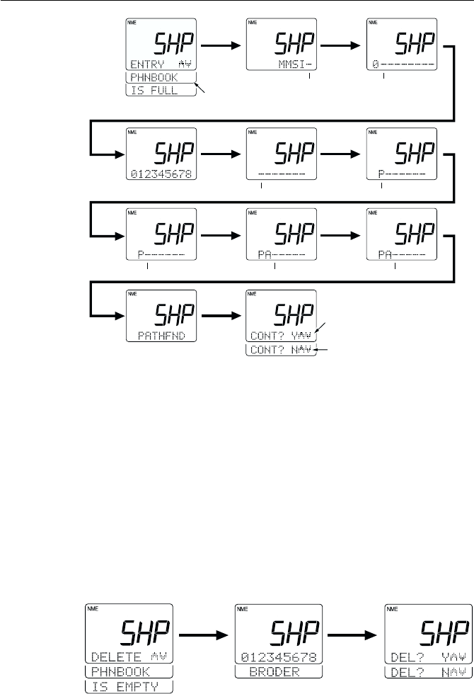
3-56 Operations
Deleting Ship Stations from the List
The oldest MMSI number and nickname flashes on the dot matrix display.
Press the SQ UP/DOWN key to display all registered stations. To delete
the contents indicated, press the ENT key and the message DEL? Y is
displayed. Press the ENT key to process the deletion and exit the Menu
operation. To exit without deleting, press the SQ UP/DOWN key until
DEL? N is displayed. Press the ENT key and operation returns operation
to the mode before the Menu operation began.
If the list has no stations entered, the message PHNBOOK IS EMPTY
HOLD DOWN CLR KEY is displayed. Press and hold the CLR key for 3
seconds to exit Menu mode.
ENT
ENT
press 0
ENT 7/PQRS
2/ABC
ENT
REPEAT ENT
Flashing Flashing
FlashingFlashing
Flashing Flashing Flashing
This display is shown only if the list already
has the maximum 20 stations registered
Pressing ENT while "N" is displayed
exits Menu mode without registering
the station.
Pressing ENT while "Y" is displayed
registers the station and exits Menu
mode.
ENT ENT
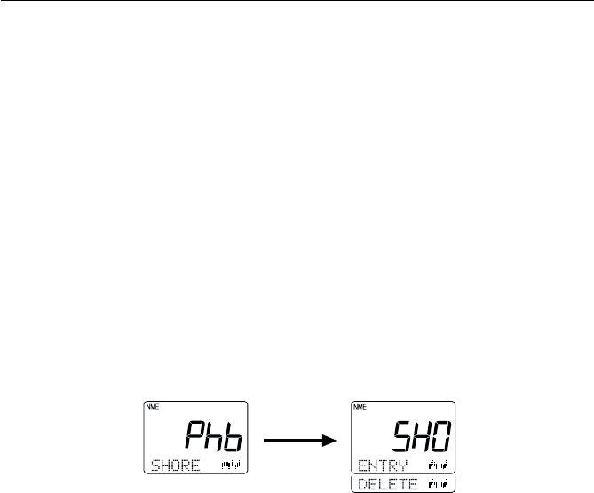
3-57
Operations
Modifying the List of Shore Stations
In this operation, a shore (coast) station is registered (added) to or deleted
from the phonebook list.
1) When SHORE is displayed, press the ENT key. The 7-segment display
shows SHO, while on the dot matrix display shows ENTRY.
2) The ENTRY selection is used to register (add) an item to the list. Press
the ENT key to accept.
The list can hold a maximum of 20 entries. If a list is already full or if the
list becomes full during this process, operation returns to the EDIT
mode and the indicator PHNBOOK IS FULL is displayed.
3) To delete an item from the list, use the SQ UP/DOWN key to select
DELETE and press the ENT key. If no station has yet been registered,
the message PHNBOOK IS EMPTY is displayed.
Note: Pressing and holding the CLR key for 3 seconds during either
ENTRY or DELETE returns operation to the mode before the Menu
operation began.
Adding Shore Stations to the List
Adding to the phonebook list for shore stations is made in the order:
MMSI number and nickname of the station.
1) When the message CONT? Y appears, press the ENT key to submit the
registration.
2) To enter the MMSI number, press the corresponding numeric keys
(0 through 9). The currently selected location is indicated by a flashing
"–" character. Pressing a numeric key enters that value then advances
to the next digit's place. To go back by 1 digit, press the CLR key.
ENT
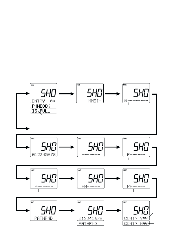
3-58 Operations
3) To enter the nickname, use the numeric keys (0 through 9) to input their
associated alpha or numeric value (refer to section 3.2 Controls and
LCD Display). The currently selected location is indicated by a flashing
"–" character. After inputting the desired letter or numeral, press the
ENT key to submit the entry and proceed to the next place. To go back
by 1 digit, press the CLR key.
If no nickname is to be registered, press the ENT key for all characters
so that they all display a "–".
ENT ON1-8 press 0
ENT ENT 7/PQRS
2/ABC
ENT
REPEAT
ENT
ENT
To DELETE mode
Flashing
FlashingFlashing
Flashing FlashingFlashing
If the maximum 20 stations are already registered, this
display is shown and the radio shifts to Delete mode
After "MMSI" is displayed, the
flashing segment is ready for input
Pressing ENT while "N" is displayed
exits Menu mode without registering
the station.
Pressing ENT while "Y" is displayed
registers the station and exits Menu
mode.
Note:
The 0 key will enter only the numeral "0", while the 1 key will alternately
enter "1" and "space". The 0 and 1 keys do not have associated alpha
characters.
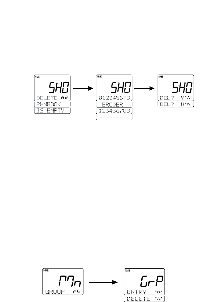
3-59
Operations
Deleting Shore Stations from the List
The oldest MMSI number and nickname registered flashes on the dot
matrix display. Press the SQ UP/DOWN key to display the registered
stations. To delete the contents indicated, press the ENT key and the
message DEL? Y is displayed. Press the ENT key to process the deletion
and exit the Menu operation. To exit without deleting, press the SQ UP/
DOWN key until DEL? N is displayed. Press the ENT key and operation
returns to the mode before the Menu operation began.
If the phonebook list has no stations entereed, the message PHNBOOK IS
EMPTY HOLD DOWN CLR KEY is displayed. Press and hold the CLR key
for 3 seconds to exit Menu mode.
3.5.30.3.4 Modifying the MMSI Group Number3.5.30.3.4 Modifying the MMSI Group Number
3.5.30.3.4 Modifying the MMSI Group Number3.5.30.3.4 Modifying the MMSI Group Number
3.5.30.3.4 Modifying the MMSI Group Number
(GROUP)(GROUP)
(GROUP)(GROUP)
(GROUP)
This operation modifies the MMSI number to be used in receiving a Group
Digital Selective Call.
1) As described in section 3.5.30.3 DSC Operation above, select the DSC
operation GROUP.
2) Press the ENT key to initiate the process. The 7-segment display shows
GrP and the dot matrix display shows ENTRY.
3) Use the SQ UP/DOWN key to alternate between ENTRY or DELETE.
4) Press the ENT key to turn to submit the desired selection.
ENT ENT
ENT
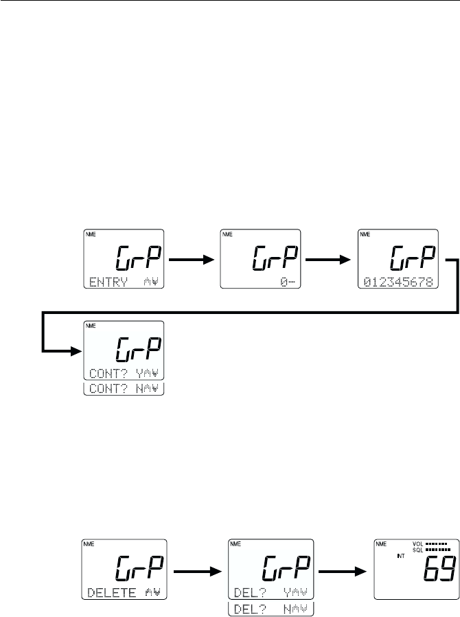
3-60 Operations
Adding a Group to the List
To add a group to the list, select ENTRY then press the ENT key. Use the
numeric keys (0 through 9) to input desired group number. The currently
selected location is indicated by a flashing "–" character. Pressing a numeric
key enters that value then advances to the next place. To go back by 1
digit, press the CLR key.
After the last position has been filled, the message CONT? Y appears.
Press ENT to register the group and exit the Menu operation. To exit
without registering, press SQ UP/DOWN until DEL? N is displayed. Press
the ENT key and operation returns to mode before the Menu operation n.
ENT ENT
ENT ENT
ENT
Deleting a Group from the List
Use the SQ UP/DOWN key to select DELETE. To delete the contents
indicated, press the ENT key and the message DEL? Y is displayed. Press
the ENT key to process the deletion and exit the Menu operation. To exit
without deleting, press the SQ UP/DOWN key until DEL? N is displayed.
Press the ENT key and operation returns to the mode before the Menu
operation began.
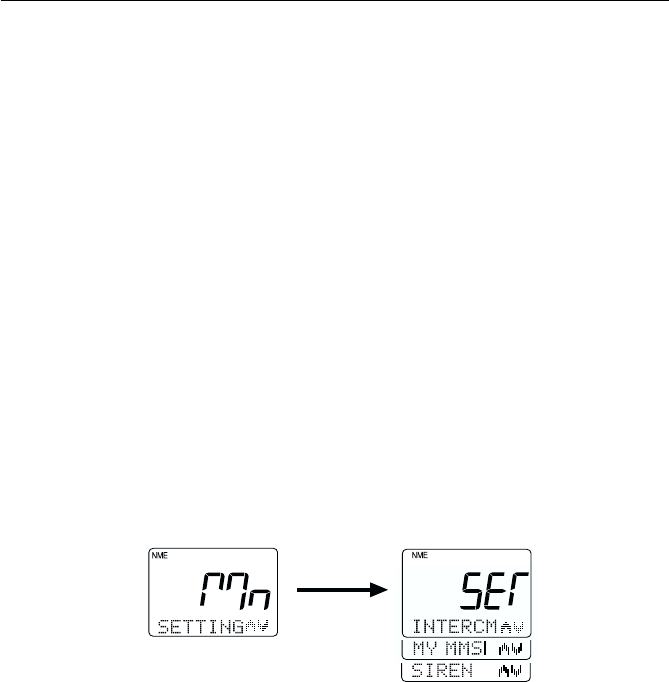
3-61
Operations
3.5.30.4 Setting Operation (RAY230)3.5.30.4 Setting Operation (RAY230)
3.5.30.4 Setting Operation (RAY230)3.5.30.4 Setting Operation (RAY230)
3.5.30.4 Setting Operation (RAY230)
This operation sets the function features of the unit, the name of the
Intercom station, the unit’s MMSI number, and the call tone/type of the
siren.
1) Press the FUNC key followed by the MENU key to initiate the Menu
mode. Mn is shown on the 7-segment display and NAVSTAT appears
on the dot matrix display.
2) Press the SQ UP/DOWN key to select SETTING.
3) Press the ENT key. The message SET appears on the 7-segment display
and INTERCM appears on the dot matrix display. Pressing the SQ UP/
DOWN key alternates between the following:
INTRCM selects the Intercom setting
MY MMSI selects the MMSI number for this unit
SIREN selects the Fog Alert siren setting
4) Select the desired operation and press the ENT key to submit your
selection.
To exit the Setting operation, press and hold he CLR key for 3 seconds.
3.5.30.4.1 Intercom Set Up3.5.30.4.1 Intercom Set Up
3.5.30.4.1 Intercom Set Up3.5.30.4.1 Intercom Set Up
3.5.30.4.1 Intercom Set Up
During an Intercom call, the name of the handset being called (or the name
of the handset initiating the call) appears in the dot matrix display. Initially,
this name is HANDSET 1, HANDSET 2, or HANDSET 3. This identifier
name and the alert tone sounded when receiving an Intercom call can be
chosen from among four types.
To change the Station name or Intercom tone:
1) Select the INTRCM operation as described above in section 3.5.30.4
Setting Operation (RAY230).
ENT
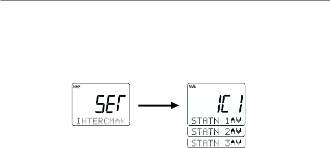
3-62 Operations
2) Press the ENT key. The 7-segment display shows IC1 and the dot
matrix display indicates STATN 1.
3) Press the SQ UP/DOWN key scroll to STATN 2 and STATN 3. The
indication on the 7-segment display changes to IC2 or IC3, respectively.
4) When the desired station name is displayed, press the ENT key to
submit.
5) To enter the new station name, use the numeric keys (0 through 9) to
input the associated alpha or numeric value (refer to section 3.2 Controls
and LCD Display). The currently selected location is indicated by the
flashing "–" character. After inputting the desired letter or numeral,
press the ENT key to submit the entry and proceed to the next place.
To go back by 1 digit, press the CLR key.
6) After entering all the desired characters, press the ENT key. The
message RING 1 is now displayed, prompting you to setup the ring
tone.
7) To change the tone, press the SQ UP/DOWN key to alternate between
RING 2, RING 3, and RING 4. As you scroll, the corresponding call tone
sounds from the handset.
8) When you hear the desired call tone, press the ENT key. The contents
of your changes are scrolled across the LCD.
9) If the contents are acceptable, press the ENT key to confirm. The
message CONT? Y is displayed.
10) Press the ENT key to register the changes.
To exit without making the changes, press the SQ UP/DOWN key until
DEL? N is displayed. Press the ENT key and operation returns to the mode
before the Menu operation began.
ENT
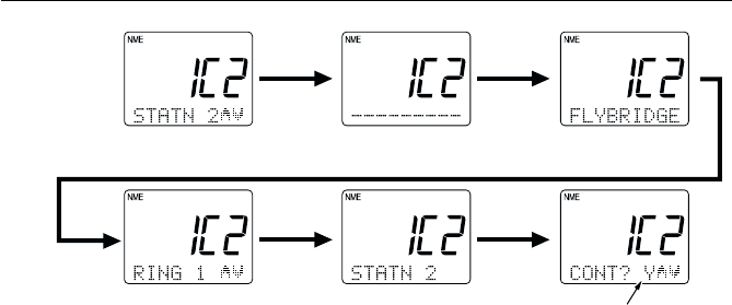
3-63
Operations
3.5.30.4.2 MMSI Number Set Up3.5.30.4.2 MMSI Number Set Up
3.5.30.4.2 MMSI Number Set Up3.5.30.4.2 MMSI Number Set Up
3.5.30.4.2 MMSI Number Set Up
This operation stores the MMSI number required for DSC communications,
including distress calls. You can request an MMSI number when you
apply for a radio license. If your vessel does not require a license, you may
obtain an MMSI by contacting either BoatUS (www.boatus.com) or
MariTEL (www.maritelusa.com).
Regulations in some regions do not allow end users to program their own
MMSI number. If this unit was purchased to be used in such a region, this
function will be disabled and the programming must be done by your
distributor.
Note:
This is a one-time operation. Once the MMSI number has been
programmed, you will not be able to change it.
Until the MMSI number is programmed, pressing the INDV, ALL SHIP,
and DISTRESS buttons will only sound an error alert.
To register the MMSI Number into memory:
1) Select the MY MMSI function as described above in Section 3.5.30.4
Setting Operation (RAY230).
2) Press the ENT key. The 7-segment display shows MS and the dot
matrix display scrolls PLEASE PROGRAM MMSI NO.
3) Press ENT. Nine underscore characters appear, which are placeholders
for the 9 digits of the MMSI number. The first character place to be
input is flashing.
To register your setup changes, press ENT
when "Y" is displayed. To exit without
saving, press ENT when "N" is displayed.
ENT NAME
ENT NAME
ENT

3-64 Operations
Pressing the following keys initiate the corresponding operation:
KeysKeys
KeysKeys
Keys ActionAction
ActionAction
Action
0 - 9 keys Changes the flashing numeric value, then advances to
the next digit's place.
ENT key Advances the (flashing) subject item to the next one
without changing the numeric value. Advances to the
next screen after entering the last (ninth) digit.
CLR key Returns to the previous subject item. Pressing and
holding for 3 seconds exits the operation and returns
to the mode before the Menu Operation began.
4) Input your MMSI number using the numeric keypad.
5) Press the ENT key. The message ENT - ACCEPT, CLR - EXIT scrolls
across the display.
6) Press the ENT key to submit the number. The message ENTER MMSI
NO. AGAIN is displayed.
7) Press ENT. The nine underscore placeholders appear once more.
8) Again input the MMSI number with the numeric keypad.
9) Press ENT to submit. If the second MMSI number you input matches
the first, the message ENT - ACCEPT, CLR - EXIT is again displayed.
Note: If the two MMSI numbers don’t match, the message MMSI NO. NOT
MATCH PRESS ENT scrolls across the display. Press ENT to exit the
Menu mode and try again from step 1.
10) Press ENT to verify. The message ENT - STORE, CLR - EXIT is
displayed.
11) Press ENT one last time to register the MMSI number in memory.
Operation returns to the mode before the Menu mode began.
To exit without making changes at any time, press and hold CLR for 3
seconds.
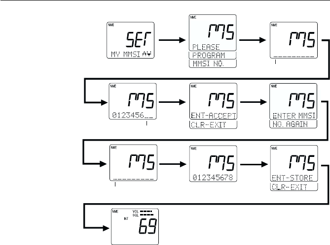
3-65
Operations
Flashing
Flashing
Flashing
ENT
ENT
Input MMSI number
using numeric keypad
ENT
ENT
ENT
re-enter
MMSI No.
ENT
ENT
3.5.30.4.3 Siren Set Up3.5.30.4.3 Siren Set Up
3.5.30.4.3 Siren Set Up3.5.30.4.3 Siren Set Up
3.5.30.4.3 Siren Set Up
This operation changes the tone of the siren that sounds from the Hailer
Horn speaker when the SIREN option is selected in Fog/Siren mode, as
described in Section 3.5.18.
To select the siren tone:
1) Select the SIREN function as described above in Section 3.5.30.4 Setting
Operation (RAY230).
2) Press the ENT key. The 7-segment display shows Sir, the dot matrix
display indicates CODENC1, and the corresponding call tone sounds
from the handset.
3) To change the tone, press the SQ UP/DOWN key to alternate between
CODENC2, CODENC3, and CODENC4. As you scroll, the corresponding
siren tone sounds from the handset. The table that follows describes
the type of tone emitted and the procedure for sounding the siren
while in Fog/Siren mode. Mn is shown on the 7-segment display and
NAVSTAT appears on the dot matrix display.
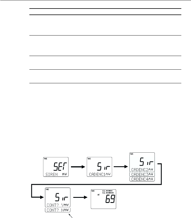
3-66 Operations
4) When the desired call tone is heard, press the ENT key to accept. The
message CONT? Y is displayed.
5) Press the ENT key to register the changes.
To exit without making the changes, press the SQ UP/DOWN key until
DEL? N is displayed. Press the ENT key and operation returns to the mode
before the Menu operation began.
NameName
NameName
Name SoundSound
SoundSound
Sound Operating Siren in Fog/Siren ModeOperating Siren in Fog/Siren Mode
Operating Siren in Fog/Siren ModeOperating Siren in Fog/Siren Mode
Operating Siren in Fog/Siren Mode
CODENC1 “Hi-Lo” Press and release PTT switch to emit
continous sound. Press PTT again to
stop.
CODENC2 Siren Press and release PTT switch to emit
continuous sound. Press PTT again
to stop.
CODENC3 Whelp Press and hold PTT switch to emit sound.
Release PTT to stop.
CODENC4 Air Horn Press and hold PTT switch to emit sound.
Release PTT to stop.
ENT
ENT
Pressing ENT while "Y" is displayed stores
the selected siren and exits Menu mode.
Pressing ENT while "N" is displayed exits
Menu mode without changing the siren.
SQ UP/
DOWN
ENT
Pressing SQ UP/DOWN
changes the siren sound
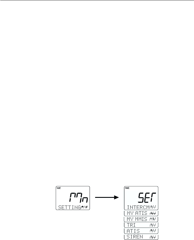
3-67
Operations
3.5.30.5 Setting Operation (RAY230E)3.5.30.5 Setting Operation (RAY230E)
3.5.30.5 Setting Operation (RAY230E)3.5.30.5 Setting Operation (RAY230E)
3.5.30.5 Setting Operation (RAY230E)
This operation sets the function features of the RAY230E: the name of the
Intercom station, the ATIS ID number and on/off state, the MMSI number,
the Tri-Watch function, and the call tone type of the siren.
1) Press the FUNC key followed by the MENU key to initiate the Menu
mode. Mn is shown on the 7-segment display and NAVSTAT appears
on the dot matrix display.
2) Press the SQ UP/DOWN key to select SETTING.
3) Press the ENT key. The message SET appears on the 7-segment display
and INTERCM appears on the dot matrix display. Pressing the SQ UP/
DOWN key alternates between the following:
INTRCM selects the Intercom setting
MY ATIS registers the ATIS ID number
MY MMSI registers the MMSI number
TRI selects the Tri-Watch operation
ATIS turns the ATIS function ON or OFF
SIREN selects the siren setting
4) Select the desired operation and press the ENT key to submit your
selection.
ENT

3-68 Operations
3.5.30.5.1 Intercom Set Up3.5.30.5.1 Intercom Set Up
3.5.30.5.1 Intercom Set Up3.5.30.5.1 Intercom Set Up
3.5.30.5.1 Intercom Set Up
The operation is identical to the Intercom operation described for the
RAY230 in section 3.5.30.4.1.
3.5.30.5.2 MY ATIS Set Up3.5.30.5.2 MY ATIS Set Up
3.5.30.5.2 MY ATIS Set Up3.5.30.5.2 MY ATIS Set Up
3.5.30.5.2 MY ATIS Set Up
This operation stores the ATIS number required for the Automatic
Transmission Identification System used in inland waterways of some
European countries. You can request an ATIS number when you apply for
a radio license.
Regulations in some regions do not allow end users to program their own
ATIS number. If this unit was purchased to be used in such a region, this
function will be disabled and the programming must be done by your
distributor.
Note:
This is a one-time operation. Once the ATIS number has been programmed,
you will not be able to change it.
The ATIS ID number is a ten digit number, beginning with a “9”. The MY
ATIS set up process has you input only the last 9 digits. The leading “9”
is automatically input for you.
To register the ATIS Number into memory:
1) Select the MY ATIS function as described above in Section 3.5.30.5
Setting Operation (RAY230E).
2) Press the ENT key. The 7-segment display shows AId and the dot
matrix display scrolls PLEASE PROGRAM ATIS ID.
3) Press ENT. Nine underscore characters appear, which are placeholders
for the last 9 digits of the ATIS number. The first character place to be
input is flashing.
Pressing the following keys initiate the corresponding operation:

3-69
Operations
4) Input your ATIS number using the numeric keypad.
5) Press the ENT key. The message ENT - ACCEPT, CLR - EXIT scrolls
across the display.
6) Press the ENT key to submit the number. The message ENTER ATIS ID
AGAIN is displayed.
7) Press ENT. The nine underscore placeholders appear once more.
8) Again input the ATIS number with the numeric keypad.
9) Press ENT to submit. If the second ATIS number you input matches
the first, the message ENT - ACCEPT, CLR - EXIT is again displayed.
NOTE: If the two ATIS numbers don’t match, the message ATIS ID NOT
MATCH PRESS ENT scrolls across the display. Press ENT to exit the
Menu mode and try again from step 1.
10) Press ENT to verify. The message ENT - STORE, CLR - EXIT is
displayed.
11) Press ENT one last time to register the ATIS number in memory.
Operation returns to the mode before the Menu operation began.
To exit without making changes at any time, press and hold CLR for 3
seconds.
KeysKeys
KeysKeys
Keys ActionAction
ActionAction
Action
0 - 9 keys Changes the flashing numeric value, then advances to
the next digit's place.
ENT key Advances the (flashing) subject item to the next one
without changing the numeric value. Advances to the
next screen after entering the last (ninth) digit.
CLR key Returns to the previous subject item. Pressing and
holding for 3 seconds exits the operation and returns
to the mode before the Menu Operation began.
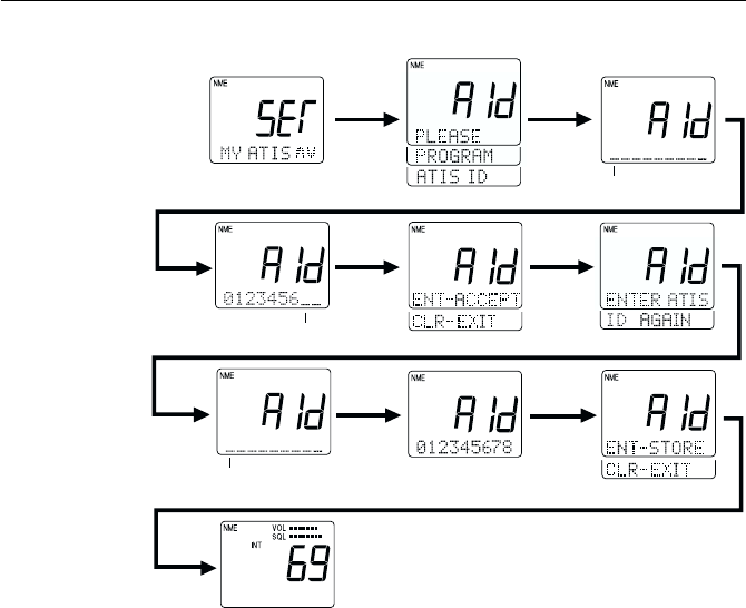
3-70 Operations
Flashing
Flashing
Flashing
ENT
ENT
Input last 9 digits of
ATIS number using
numeric keypad
ENT
ENT
ENT
re-enter
ATIS No.
ENT
ENT

3-71
Operations
3.5.30.5.3 MY MMSI Set Up3.5.30.5.3 MY MMSI Set Up
3.5.30.5.3 MY MMSI Set Up3.5.30.5.3 MY MMSI Set Up
3.5.30.5.3 MY MMSI Set Up
The operation is identical to the MMSI set up operation described for the
RAY230 in section 3.5.30.4.2 MY MMSI Set Up.
3.5.30.5.4 Tri-Watch Set Up3.5.30.5.4 Tri-Watch Set Up
3.5.30.5.4 Tri-Watch Set Up3.5.30.5.4 Tri-Watch Set Up
3.5.30.5.4 Tri-Watch Set Up
This operation selects whether the Weather Channel or the Multi-Call
Channel is monitored during Tri-Watch state in the US mode.
To change the monitored channel:
1) Per the description in section 3.5.30.8 Setting Operation above, select
TRI.
2) Press the ENT key. TrI appears on the 7-segment display and TRI WX
appears on the dot matrix.
3) Press the SQ UP/DOWN key to toggle between TRI MUL for Multi-
Call and TRI WX for Weather Channel.
4) After selecting the desired operation, press the ENT key.
5) If the setting is acceptable, press the ENT key to confirm. The message
CONT? Y is displayed.
6) Press the ENT key to register the setting.
To exit without making changes, press the SQ UP/DOWN key until DEL?
N is displayed. Press the ENT key and operation returns to the mode
before the Menu operation began.
ENT ENT

3-72 Operations
3.5.30.5 ATIS Set Up3.5.30.5 ATIS Set Up
3.5.30.5 ATIS Set Up3.5.30.5 ATIS Set Up
3.5.30.5 ATIS Set Up
This operation determines whether to effect ID transmission of ATIS after
the PTT switch is released.
When the ATIS transmission is set to the ON position, the ATIS sound is
automatically suppressed by the “ATIS Killer” feature.
To set the ATIS function:
1) Per the description in Section 3.5.30.5 Setting Operation (RAY230E)
above, select ATIS.
2) Press the ENT key. The message ATS is shown on the 7-segment
display and ATIS OFF appears on the dot matrix.
3) Press the SQ UP/DOWN key to toggle between ATIS ON and ATIS
OFF.
4) After selecting the desired operation, press the ENT key.
5) If the setting is acceptable, press the ENT key to confirm. The message
CONT? Y is displayed.
6) Press the ENT key to register the setting. When ATIS is ON, the ATIS
indicator is illuminated on the LCD.
To exit without making changes, press the SQ UP/DOWN key until DEL?
N is displayed. Press the ENT key and operation returns to the mode
before the Menu operation began.
3.5.30.5.6 Siren Set Up3.5.30.5.6 Siren Set Up
3.5.30.5.6 Siren Set Up3.5.30.5.6 Siren Set Up
3.5.30.5.6 Siren Set Up
The operation is identical to the Siren set up operation described for the
RAY230 in section 3.5.30.4.2.MY MMSI Set Up.
ENT ENT

3-73
Operations
3.5.31 RAY230/RAY230E Marine Channels3.5.31 RAY230/RAY230E Marine Channels
3.5.31 RAY230/RAY230E Marine Channels3.5.31 RAY230/RAY230E Marine Channels
3.5.31 RAY230/RAY230E Marine Channels
International Mode Frequency TableInternational Mode Frequency Table
International Mode Frequency TableInternational Mode Frequency Table
International Mode Frequency Table
Note:
International VHF frequency usage varies from country to country. Insure you are
familiar with the channel requirements of the country where you are boating before
using any VHF transceiver.
INT(International) Mode
Channel Frequency (MHz)
TYPE OF TRAFFIC
Function
Desig. TX RX SHIP SHIP
TO SHIP TO SHORE
01 156.050 160.650 Port Operations YES
02 156.100 160.700 Port Operations YES
03 156.150 160.750 Port Operations YES
04 156.200 160.800 Port Operations YES
05 156.250 160.850 Port Operations YES
06 156.300 156.300 Intership Safety YES
07 156.350 160.950 Port Operations YES
08 156.400 156.400 Intership YES
09 156.450 156.450 Calling YES
10 156.500 156.500 Port Operations YES
11 156.550 156.550 Port Operations YES
12 156.600 156.600 Port Operations YES
13 2 2
2 2
2 156.650 156.650 Port Operations YES
14 156.700 156.700 Port Operations YES
15 1 1
1 1
1 156.750 Port Operations — —
16 156.800 156.800 Emergency, Calling YES
17 3 3
3 3
3 156.850 156.850 Port Operations YES
18 156.900 161.500 Port Operations YES
19 156.950 161.550 Public Correspondence YES
20 157.000 161.600 Public Correspondence YES
21 157.050 161.650 Public Correspondence YES
22 157.100 161.700 Public Correspondence YES
23 157.150 161.750 Public Correspondence YES
24 157.200 161.800 Public Correspondence YES
25 157.250 161.850 Public Correspondence YES
26 157.300 161.900 Public Correspondence YES
27 157.350 161.950 Public Correspondence YES
28 157.400 162.000 Public Correspondence YES
60 156.025 160.625 Port Operations YES
61 156.075 160.675 Port Operations YES

3-74 Operations
Channel Frequency (MHz)
TYPE OF TRAFFIC
Function
Desig. TX RX SHIP SHIP
TO SHIP TO SHORE
62 156.125 160.725 Port Operations YES
63 156.175 160.775 Port Operations YES
64 156.225 160.825 Port Operations YES
65 156.275 160.875 Port Operations YES
66 156.325 160.925 Port Operations YES
67 156.375 156.375 Intership YES
68 156.425 156.425 Port Operations YES
69 156.475 156.475 Port Operations YES
70 4 4
4 4
4 156.525 156.525 DSC — —
71 156.575 156.575 Port Operations YES
72 156.625 156.625 Intership YES
73 156.675 156.675 Port Operations YES
74 156.725 156.725 Port Operations YES
75 1 1
1 1
1 156.775 CH16 Guard Band — —
76 1 1
1 1
1 156.825 CH16 Guard Band — —
77 3 3
3 3
3 156.875 156.875 Intership YES
78 156.925 161.525 Public Correspondence YES
79 156.975 161.575 Public Correspondence YES
80 157.025 161.625 Public Correspondence YES
81 157.075 161.675 Public Correspondence YES
82 157.125 161.725 Public Correspondence YES
83 157.175 161.775 Public Correspondence YES
84 157.225 161.825 Public Correspondence YES
85 157.275 161.875 Public Correspondence YES
86 157.325 161.925 Public Correspondence YES
87 157.375 161.975 Public Correspondence YES
88 157.425 162.025 Port Operations YES
Notes:
1 : Transmitter is automatically disabled on Channel 15, 75 and 76 in INT mode.
2 : 1 Watt initially. User can override to high power via front panel controls.
3 : 1 Watt only.
4 : Channel 70 is used for Digital Selective Calling (DSC) only.
Important Notice
The INT mode is not legal for use while operating in U.S. waters. The TX/RX frequencies
available in the INT mode were agreed upon by the attending countries at the 1968
ITU-International Telecommunication Union meeting in Geneva, and are legal for use
in International waters only.

3-75
Operations
Canada Mode Frequency Table for the RAY230Canada Mode Frequency Table for the RAY230
Canada Mode Frequency Table for the RAY230Canada Mode Frequency Table for the RAY230
Canada Mode Frequency Table for the RAY230
Canada Mode
Channel Frequency (MHz)
TYPE OF TRAFFIC
Function
Desig. TX RX SHIP SHIP
TO SHIP TO SHORE
01 156.050 156.050 VTS,Port Operation YES
02 156.100 156.100 Port Operation YES
03 4 4
4 4
4 156.150 156.150 Port Operation YES
04 156.200 156.200 Canadian Coast Guard, SAR YES
05 156.250 156.250 Port Operation YES
06 156.300 156.300 Intership Safety YES
07 156.350 156.350 Commercial YES
08 156.400 156.400 Commercial YES
09 156.450 156.450 Calling YES
10 156.500 156.500 Commercial YES
11 156.550 156.550 Commercial YES
12 156.600 156.600 Port Operation YES
13 2 2
2 2
2 156.650 156.650 Navigation, Bridge to Bridge YES
14 156.700 156.700 Port Operation YES
15 1 1
1 1
1 156.750 Environmental — —
16 156.800 156.800 Emergency, Calling YES
17 3 3
3 3
3 156.850 156.850 State Controlled YES
18 156.900 156.900 Commercial YES
19 156.950 156.950 Commercial YES
20 157.000 157.000 Port Operation YES
21 4 4
4 4
4 157.050 157.050 Coast Guard YES
22 4 4
4 4
4 157.100 157.100 Coast Guard YES
23 4 4
4 4
4 157.150 157.150 Coast Guard YES
24 157.200 161.800 Marine Operator YES
25 157.250 161.850 Marine Operator YES
26 157.300 161.900 Marine Operator YES
27 157.350 161.950 Marine Operator YES
28 157.400 162.000 Marine Operator YES
60 4 4
4 4
4 156.025 156.025 Canadian Coast Guard YES
61 4 4
4 4
4 156.075 156.075 Canadian Coast Guard YES
62 4 4
4 4
4 156.125 156.125 Canadian Coast Guard YES
63 156.175 156.175 Canadian Coast Guard YES
64 4 4
4 4
4 156.225 156.225 Canadian Coast Guard YES
65 156.275 156.275 Port Operation YES
66 156.325 156.325 Port Operation YES

3-76 Operations
Channel Frequency (MHz)
TYPE OF TRAFFIC
Function
Desig. TX RX SHIP SHIP
TO SHIP TO SHORE
67 2 2
2 2
2 156.375 156.375 Commercial YES
68 156.425 156.425 Boat Operations, Recreational YES
69 156.475 156.475 Boat Operations, Recreational YES
70 5 5
5 5
5 156.525 156.525 DSC — —
71 156.575 156.575 Boat Operations, Recreational YES
72 156.625 156.625 Boat Operations, Recreational YES
73 156.675 156.675 Port Operation YES
74 156.725 156.725 Port Operation YES
75 1 1
1 1
1 156.775 CH16 Guard Band — —
76 1 1
1 1
1 156.825 CH16 Guard Band — —
77 3 3
3 3
3 156.875 156.875 Port Operation YES
78 156.925 156.925 Boat Operations, Recreational YES
79 156.975 156.975 Commercial YES
80 157.025 157.025 Commercial YES
81 4 4
4 4
4 157.075 157.075 Coast Guard YES
82 4 4
4 4
4 157.125 157.125 Coast Guard YES
83 157.175 157.175 Coast Guard YES
84 157.225 161.825 Marine Operator YES
85 157.275 161.875 Marine Operator YES
86 157.325 161.925 Marine Operator YES
87 157.375 161.975 Marine Operator YES
88 157.425 157.425 Commercial YES
Notes:
1: Transmitter is automatically disabled on Channel 15, 75 and 76 in Canada
mode.
2: 1 Watt initially. User can override to high power via front panel controls
3: 1 Watt only.
4: Not for use by general public.
Requires special authorization from the Canadian Coast Guard, or under private
land mobile license.
5: Channel 70 is used for Digital Selective Calling (DSC) only.
Important Notice
The Canada mode is not legal for use while operating in U.S. waters.

3-77
Operations
US Mode Frequency TableUS Mode Frequency Table
US Mode Frequency TableUS Mode Frequency Table
US Mode Frequency Table
USA Mode
Channel Frequency (MHz)
TYPE OF TRAFFIC
Function
Desig. TX RX SHIP SHIP
TO SHIP TO SHORE
1 156.050 156.050 VTS/Port Operations YES
03 4 4
4 4
4 156.150 156.150 Port Operations YES
05 156.250 156.250 Port Operations YES
06 156.300 156.300 Intership Safety YES
07 156.350 156.350 Commercial YES
08 156.400 156.400 Commercial YES
09 156.450 156.450 Calling YES
10 156.500 156.500 Commercial YES
11 156.550 156.550 Commercial YES
12 156.600 156.600 Port Operations YES
13 2 2
2 2
2 156.650 156.650 Navigation,Bridge to Bridge YES
14 156.700 156.700 Port Operations YES
15 1 1
1 1
1 156.750 Environmental — —
16 156.800 156.800 Emergency, Calling YES
17 3 3
3 3
3 156.850 156.850 State Controlled YES
18 156.900 156.900 Commercial YES
19 156.950 156.950 Commercial YES
20 157.000 157.000 Port Operations YES
21 4 4
4 4
4 157.050 157.050 Coast Guard YES
22 4 4
4 4
4 157.100 157.100 Coast Guard YES
23 4 4
4 4
4 157.150 157.150 Coast Guard YES
24 157.200 161.800 Marine Operator YES
25 157.250 161.850 Marine Operator YES
26 157.300 161.900 Marine Operator YES
27 157.350 161.950 Marine Operator YES
28 157.400 162.000 Marine Operator YES
61 4 4
4 4
4 156.075 156.075 Canadian Coast Guard YES
63 156.175 156.175 Canadian Coast Guard YES
64 4 4
4 4
4 156.225 156.225 Canadian Coast Guard YES
65 156.275 156.275 Port Operations YES —
66 156.325 156.325 Port Operations YES
67 2 2
2 2
2 156.375 156.375 Commercial YES
68 156.425 156.425 Boat Operations,Recreational YES
69 156.475 156.475 Boat Operations,Recreational YES
70 5 5
5 5
5 156.525 156.525 DSC — —
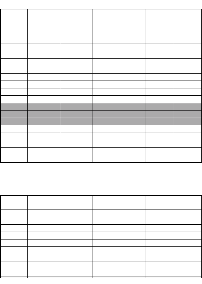
3-78 Operations
Channel Frequency (MHz)
TYPE OF TRAFFIC
Function
Desig. TX RX SHIP SHIP
TO SHIP TO SHORE
71 156.575 156.575 Boat Operations,Recreational YES
72 156.625 156.625 Boat Operations,Recreational YES
73 156.675 156.675 Port Operations YES
74 156.725 156.725 Port Operations YES
75 1 1
1 1
1 — 156.775 CH 16 Guard Band — —
76 1 1
1 1
1 — 156.825 CH 16 Guard Band — —
77 3 3
3 3
3 156.875 156.875 Port Operations YES
78 156.925 156.925 Boat Operations,Recreational YES
79 156.975 156.975 Commercial YES
80 157.025 157.025 Commercial YES
81 4 4
4 4
4 157.075 157.075 Coast Guard YES
82 4 4
4 4
4 157.125 157.125 Coast Guard YES
83 157.175 157.175 Coast Guard YES
84 157.225 161.825 Marine Operator YES
85 157.275 161.875 Marine Operator YES
86 157.325 161.925 Marine Operator YES
87 157.375 161.975 Marine Operator YES
88 157.425 157.425 Commercial YES
Weather Channels and FrequenciesWeather Channels and Frequencies
Weather Channels and FrequenciesWeather Channels and Frequencies
Weather Channels and Frequencies
CH RX Frequency TYPE OF TRAFFIC FUNCTION-SHIP TO
SHORE
0 163.275 NOAA Weather Receive only
1 162.550 NOAA Weather Receive only
2 162.400 NOAA Weather Receive only
3 162.475 NOAA Weather Receive only
4 162.425 NOAA Weather Receive only
5 162.450 NOAA Weather Receive only
6 162.500 NOAA Weather Receive only
7 162.525 NOAA Weather Receive only
8 161.650 Canadian Weather Receive only
9 161.775 Canadian Weather Receive only

3-79
Operations
Notes:
1: Transmitter is automatically disabled on Channel 15, 75 and 76 in US mode.
2: 1 Watt initially. User can override to high power by pressing and holding PTT
and the 9/1/25 key.
3: 1 Watt only.
4: Not for use by general public.
Requires special authorization from the U.S. Coast Guard, or under private land
mobile license.
5: Channel 70 is used for Digital Selective Calling (DSC) only.
Important Notice
Channel 3, 21, 23, 61, 64, 81, 82 and 83 (shaded) are not for use by the general public in
U.S. water.
These frequencies may be used only under authorization by the U.S. Coast Guard, or
under private land mobile license.

3-80 Operations

4-1
Technical Description
Section 4 TECHNICAL DESCRIPTIONSection 4 TECHNICAL DESCRIPTION
Section 4 TECHNICAL DESCRIPTIONSection 4 TECHNICAL DESCRIPTION
Section 4 TECHNICAL DESCRIPTION
4.14.1
4.14.1
4.1 Base Station TransceiverBase Station Transceiver
Base Station TransceiverBase Station Transceiver
Base Station Transceiver
4.1.1 Power Supply Section4.1.1 Power Supply Section
4.1.1 Power Supply Section4.1.1 Power Supply Section
4.1.1 Power Supply Section
This equipment is rated for 13.6 VDC but can operate within a voltage
range of 11.6 - 15.6 VDC. In case the input supply voltage exceeds 15.6
VDC, the over-voltage detection circuit (D18, Q27) cuts off the relay (RL1)
to the main power supply. Reverse connection of the power supply is
protected by a diode (D17) in the relay circuit.
Pressing the Power switch on the main unit turns on the power supply via
the relay circuit. This consists of Q26 on the main RF PCB, and Q301,
D301, and IC305 on the main control PCB and is switched by Q28, Q30,
Q33, and Q34). Only the CPU system is powered on. The RF circuit (Q29,
Q30 and Q331) remains off until the power switch is pressed on the handset.
At that time, the full system is operational.
4.1.2 Receiver Section4.1.2 Receiver Section
4.1.2 Receiver Section4.1.2 Receiver Section
4.1.2 Receiver Section
The RAY230/RAY230E is equipped with two receiver units: one for All
Channels and another exclusively for Channel 70.
4.1.2.1 Antenna Switching4.1.2.1 Antenna Switching
4.1.2.1 Antenna Switching4.1.2.1 Antenna Switching
4.1.2.1 Antenna Switching
The RF-signal passes through the low-pass filter to the RF pre-amplifier
(Q16) via the antenna switching action of D1 and D2. When receiving a
signal, diodes D1 and D2 are non-conductive.
4.1.2.2 Pre-amp, Splitter (binary distribution)4.1.2.2 Pre-amp, Splitter (binary distribution)
4.1.2.2 Pre-amp, Splitter (binary distribution)4.1.2.2 Pre-amp, Splitter (binary distribution)
4.1.2.2 Pre-amp, Splitter (binary distribution)
A bifilar wound distribution circuit (L37, R89) is furnished for the RF signal
because the radio is equipped with two built-in receivers (All Channels
and Channel 70). Since the pre-amplifier is used only to compensate for the
losses caused by this circuit, the amplifier is set at a low gain level. A
BALUN system assuring low losses is adopted for the distribution circuit.

4-2 Technical Description
4.1.2.3 All Channels Receiver4.1.2.3 All Channels Receiver
4.1.2.3 All Channels Receiver4.1.2.3 All Channels Receiver
4.1.2.3 All Channels Receiver
1) RF Amplifier
The RF amplifier consists of the FET amplifier (Q18) and a Band Pass
Filter (BPF) having variable bandwidth by variable capacitance diodes
(D12-D16). The response is automatically corrected by the control
voltage supplied from the CPU to a proper value corresponding to the
receive frequency. The BPF is provided with an attenuation
characteristic of 15 dB or larger at the detuning point 3 MHz lower than
the lower limit of the receive frequency (156 MHz). Then the RF signal,
having been mixed with the 1st local oscillator signal by the 1st mixer
(Q19) after passing the BPF, is converted to the 1st Intermediate
Frequency (IF) signal (21.6 MHz).
Note:
The 1st local oscillator signal generated by a synthesizer has a frequency
lower than the desired frequency by 21.6 MHz. The 1st local oscillator
signal is fed to the 1st mixer (Q19) after being amplified by the buffer
amplifier (Q14).
2) First Intermediate Frequency (1st IF)
The 1st IF signal of 21.6 MHz supplied via the crystal filter (F1) is then
amplified by the 1st IF amplifier (Q20).
3) 2nd IF
The 1st IF signal, having been mixed with the 2nd local oscillator signal
(21.145 MHz) in the IC (IC7 Mix, Osc, Amp, Limit, Det) for the 2nd IF, is
converted into the 2nd IF signal with a frequency of 455 kHz. Further,
after subjected to amplification and successive amplitude limitation
via the ceramic filter (F2), the signal is demodulated by the Quad detector
(quadrature detection) into an audio signal.
4) De-Emphasis
An audio signal is subjected to a correction in the frequency
characteristic to -6 dB/oct by the de-emphasis circuit (IC8).
5) Squelch
Within IC 9, high frequency noise outside the voice band from the DISC
output of IC 7 is amplified by the noise amplifier and converted into a DC
voltage by the detection circuit. Then, this voltage is further amplified by
the DC amplifier (IC374B on the control PCB) to a BUSY1 signal, which is

4-3
Technical Description
fed to the squelch control port (A/D). The operation level of the squelch is
determined by the electronically controlled volume (IC313 on the control
PCB) and the set value for the A/D action of the CPU.
4.1.2.4 Channel 70 Receiver4.1.2.4 Channel 70 Receiver
4.1.2.4 Channel 70 Receiver4.1.2.4 Channel 70 Receiver
4.1.2.4 Channel 70 Receiver
1) High Frequency Amplifier
The front-end part of the Channel 70 receiver consists of the FET
amplifier (Q21) and a narrow bandwidth BPF. The BPF has an
attenuation characteristic of 15 dB or larger at the detuning point 3
MHz lower than the lower limit of the receive frequency (156 MHz).
The amplified RF signal is mixed with the local oscillator signal in the
Mixer (Q22) and converted into the 1st IF signal of 16.9 MHz. The 1st
local signal, generated by an oscillation circuit (Q24) using the 3rd
over tone of the crystal (X3, 46.5417 MHz), has a frequency of 139.625
MHz. The signal is fed to the mixer (Q22) via the buffer amplifier (Q25).
2) 1st IF
The 1st IF signal of 16.9 MHz supplied via the crystal filter (F3) is
amplified by the 1st IF amplifier (Q23).
3) 2nd IF
The 1st IF signal is mixed with the 2nd local oscillator signal (16.445
MHz) in the IC (IC9 Mix, Osc, Amp, Limit, Det) for the 2nd IF and is
converted into the 2nd IF signal with a frequency of 455 kHz. After
further amplification and successive amplitude limitation via the ceramic
filter (F4), the signal is demodulated by the Quad detector (quadrature
detection) into an audio signal.
4) De-Emphasis
An audio signal is subjected to a correction in its frequency
characteristic to a -6dB/oct by the de-emphasis circuit (IC8).
5) Squelch
Within IC9, high-frequency noise outside the voice band from the
DISC output of IC 7 is amplified by the noise amplifier and converted
into a DC voltage by the detection circuit. Then, this converted voltage
is supplied as the BUSY2 signal to the squelch control port (A/D) of
the CPU. The threshold level is set with the VR4 on the PCB, free from
any external adjustment.

4-4 Technical Description
4.1.2.5 WX Alert (Weather Channel)4.1.2.5 WX Alert (Weather Channel)
4.1.2.5 WX Alert (Weather Channel)4.1.2.5 WX Alert (Weather Channel)
4.1.2.5 WX Alert (Weather Channel)
The tone decoder (IC11) detects the 1050 Hz tone signal from IC7 via IC8,
in the Weather Channel mode.
4.1.2.6 ATIS Decode (All Channel Receiver)4.1.2.6 ATIS Decode (All Channel Receiver)
4.1.2.6 ATIS Decode (All Channel Receiver)4.1.2.6 ATIS Decode (All Channel Receiver)
4.1.2.6 ATIS Decode (All Channel Receiver)
The FSK modulated signal of 1200 bps provided in the ETS300-698 is
demodulated by the FSK Modem-1 (IC308). Since this signal is offensive
to the ear, the AF is muted by the CPU control.
4.1.2.7 DSC Decoding (Channel 70 Receiver)4.1.2.7 DSC Decoding (Channel 70 Receiver)
4.1.2.7 DSC Decoding (Channel 70 Receiver)4.1.2.7 DSC Decoding (Channel 70 Receiver)
4.1.2.7 DSC Decoding (Channel 70 Receiver)
The DSC signal of 1200 bps is demodulated by the FSK Modem-2 (IC309).
4.1.3 Transmitter Section4.1.3 Transmitter Section
4.1.3 Transmitter Section4.1.3 Transmitter Section
4.1.3 Transmitter Section
4.1.3.1 Instantaneous Deviation Control (IDC)4.1.3.1 Instantaneous Deviation Control (IDC)
4.1.3.1 Instantaneous Deviation Control (IDC)4.1.3.1 Instantaneous Deviation Control (IDC)
4.1.3.1 Instantaneous Deviation Control (IDC)
CircuitCircuit
CircuitCircuit
Circuit
After pre-emphasis of 6 dB/oct in the IDC circuit (IC6), the microphone,
DSC, and ATIS signals from the control system are supplied to an amplitude-
limiting circuit. Then the signals are passed through a fifth-order low-pass
filter for splatter prevention and supplied to the VCO. The maximum
frequency deviation is set by VR3.
4.1.3.2 Buffer Driver Amplifier4.1.3.2 Buffer Driver Amplifier
4.1.3.2 Buffer Driver Amplifier4.1.3.2 Buffer Driver Amplifier
4.1.3.2 Buffer Driver Amplifier
The carrier frequency from the VCO is supplied via the diode switch (D7)
to the buffer (Q2). The carrier is then amplified up to about 200mW, and
finally boosted to 25W by the RF power amplifier (IC1) at the final stage.
The transmitting power is supplied to the antenna via the LPF by operating
the ANT switch (D1).
4.1.3.3 Automatic Power Control (APC) Circuit4.1.3.3 Automatic Power Control (APC) Circuit
4.1.3.3 Automatic Power Control (APC) Circuit4.1.3.3 Automatic Power Control (APC) Circuit
4.1.3.3 Automatic Power Control (APC) Circuit
The transmitting power is sampled and rectified in the detection circuit
(D5). Then, this DC voltage is compared with the standard set value of the
output at the comparator circuit (IC2). This output controls both the PA
and the driver by a two-stage DC amplifier (Q5 and Q6) so that a stable
transmitting power can be supplied to the ANT. The switchover of power
between 25 W and 1 W is effected with the output changeover switch
(Q7). The output is set with VR1 for 1W or VR2 for 25W.

4-5
Technical Description
4.1.3.4 ATIS, DSC Encoding4.1.3.4 ATIS, DSC Encoding
4.1.3.4 ATIS, DSC Encoding4.1.3.4 ATIS, DSC Encoding
4.1.3.4 ATIS, DSC Encoding
The FSK modulating signal of 1200 bps is produced in the FSK Modem-1
(IC308). The modulation index is: 1.0 for ATIS and 2.0 for DSC.
4.1.4 Phase Lock Loop (PLL) Circuit4.1.4 Phase Lock Loop (PLL) Circuit
4.1.4 Phase Lock Loop (PLL) Circuit4.1.4 Phase Lock Loop (PLL) Circuit
4.1.4 Phase Lock Loop (PLL) Circuit
The standard PLL frequency of 12.8 MHz is divided by 512 to produce 25
KHz channel spacing by the PLL IC (IC4). The oscillation frequency of the
VCO, which has been divided down to 25 kHz just like the standard, is
applied to a phase comparator within IC4, producing a pulse output
corresponding to the deviation. The output pulse is converted into a DC
value through the external charge pump circuit (Q11 and Q12) and a loop
filter, which is supplied to the control terminal of the VCO as a frequency
control voltage. A part of the output from the VCO is fed back to the PLL IC
(f in) via the buffer amplifier (Q13). The loop filter is provided with a time-
constant changeover-switch using the IC3 to meet the requirement for
high-speed response by accelerating the rise characteristic at the time of
transmission/reception changeover and frequency changeover. The
detection circuit (IC5) enables the PLL unlocking signal to output without
fluttering.
4.1.5 Audio Frequency (AF) Control Section4.1.5 Audio Frequency (AF) Control Section
4.1.5 Audio Frequency (AF) Control Section4.1.5 Audio Frequency (AF) Control Section
4.1.5 Audio Frequency (AF) Control Section
4.1.5.1 AF Selection4.1.5.1 AF Selection
4.1.5.1 AF Selection4.1.5.1 AF Selection
4.1.5.1 AF Selection
AF signals (RxAF, Fog, Siren, and Hail) are selected by the AF selector
(IC310). RxAF and the received Hailer sound are transferred to the cross
point switch via the mute circuit (Q302, Q303). The Fog, Siren, and the
transmitted Hailer voice signals are transferred via the electronic volume
control circuit (IC312, IC313) to the AF amplifier, which develops across a
4 ohm speaker load.
4.1.5.2 Line Selection4.1.5.2 Line Selection
4.1.5.2 Line Selection4.1.5.2 Line Selection
4.1.5.2 Line Selection
The line selector (IC311) selects the microphone, the DSC signal, or the
IDC input (modulation input).
4.1.5.3 Speaker Selection4.1.5.3 Speaker Selection
4.1.5.3 Speaker Selection4.1.5.3 Speaker Selection
4.1.5.3 Speaker Selection
The relay circuit (RL301, Q306) switches over operation to the external
speaker.

4-6 Technical Description
4.1.5.4 Telephone I/O, Cross-Point Switch4.1.5.4 Telephone I/O, Cross-Point Switch
4.1.5.4 Telephone I/O, Cross-Point Switch4.1.5.4 Telephone I/O, Cross-Point Switch
4.1.5.4 Telephone I/O, Cross-Point Switch
The telephone line driver, receiver, DTMF oscillator, and an 8 x 8 cross-
point switch are continued in IC315. The cross-point switch selects and
combines the AF signals that correspond to the RAY230/230E's respective
operations: handset-VHF, handset-Telephone and handset-Intercom.
Connection to a telephone can be made by adding optional communication
equipment with a DTMF interface such as RAYCOM Cellular, Mini-M, etc.
4.1.6 Handset I/O4.1.6 Handset I/O
4.1.6 Handset I/O4.1.6 Handset I/O
4.1.6 Handset I/O
To connect with the handset circuit, an interface unit is provided that is
suitable for both audio and digital applications.
4.1.6.1 Audio I/O4.1.6.1 Audio I/O
4.1.6.1 Audio I/O4.1.6.1 Audio I/O
4.1.6.1 Audio I/O
A buffer circuit created by the operational amplifier (IC319 - IC321) transmits
a low-impedance AF signal between the base station and the handset.
4.1.6.2 Digital I/O4.1.6.2 Digital I/O
4.1.6.2 Digital I/O4.1.6.2 Digital I/O
4.1.6.2 Digital I/O
Because of its anti-noise characteristics, photo-couplers (PC304 - PC309)
are used to transfer the control data. The received signal data is further
subjected to waveform shaping (Q319 - Q321) and processed by the CPU.
4.1.7 NMEA Data Input4.1.7 NMEA Data Input
4.1.7 NMEA Data Input4.1.7 NMEA Data Input
4.1.7 NMEA Data Input
The circuit uses a photo-coupler (PC301) as an interface to receive data.
4.1.8 SeaTalk I/O4.1.8 SeaTalk I/O
4.1.8 SeaTalk I/O4.1.8 SeaTalk I/O
4.1.8 SeaTalk I/O
Both the transmitter and the receiver are furnished with a photo-coupled
interface to the +12 VDC power supply circuit.
4.1.9 Write Data Operation4.1.9 Write Data Operation
4.1.9 Write Data Operation4.1.9 Write Data Operation
4.1.9 Write Data Operation
The CPU writes data through the Write terminal (J302). During the write
operation, the data port of the CPU is switched to the “write” side by the
selector (IC301–IC304). The switch selection is made according to the
corresponding operation modes.

4-7
Technical Description
4.24.2
4.24.2
4.2 Handset CircuitHandset Circuit
Handset CircuitHandset Circuit
Handset Circuit
4.2.1 Outline4.2.1 Outline
4.2.1 Outline4.2.1 Outline
4.2.1 Outline
The handset is connected to the cradle to communicate control data for
various functions, such as transmission/reception of voice signals on the
handset, all key operations, LCD display, lighting by LED, monitor control
of the cradle, etc.
4.2.2 Circuit Makeup4.2.2 Circuit Makeup
4.2.2 Circuit Makeup4.2.2 Circuit Makeup
4.2.2 Circuit Makeup
The circuit consists of the following components:
•Power supply system circuit
Digital system +5V Voltage Regulator (IC701)
Analog system +5V Voltage Regulator (IC702)
Analog system +9V Voltage Regulator (IC714)
•Single Chip CPU (IC706)
•LCD Display Controller/Driver (IC709)
•LED Driver Circuit (IC710)
•Electronically-controlled Volume (IC716)
4.2.3 Power Supply System4.2.3 Power Supply System
4.2.3 Power Supply System4.2.3 Power Supply System
4.2.3 Power Supply System
The input voltage of the main supply power is +13.6V. The internal operation
voltages for the respective applications are as follows:
•+9V by the voltage regulator (IC714) for LCD lighting
•+5V by the voltage regulator (D5V, IC701) for a digital voltage
•+5V by the voltage regulator (A5V, IC702) for an analog voltage
•+5V (VTH) from emitter follower (Q703) for working bias voltage for the
voice signals
4.2.4 CPU4.2.4 CPU
4.2.4 CPU4.2.4 CPU
4.2.4 CPU
The CPU is an 8-bit, single-chip microcomputer µPD789026 (IC706).
4.2.5 Controller Driver for LCD display4.2.5 Controller Driver for LCD display
4.2.5 Controller Driver for LCD display4.2.5 Controller Driver for LCD display
4.2.5 Controller Driver for LCD display
The PCF2113DH/F4 (IC709) is a LCD controller driver used to indicate
alphanumeric characters and symbols.
4.2.6 LED Driver Circuit4.2.6 LED Driver Circuit
4.2.6 LED Driver Circuit4.2.6 LED Driver Circuit
4.2.6 LED Driver Circuit
The TB62715 FN (IC710) makes a 4-stage dimming control for the LEDs
(D704–D707) and the LCD backlight, and also turns on/off the keypad
LEDs (D708–D720).

4-8 Technical Description
4.2.7 Electronically Controlled Volume4.2.7 Electronically Controlled Volume
4.2.7 Electronically Controlled Volume4.2.7 Electronically Controlled Volume
4.2.7 Electronically Controlled Volume
The receiver's sound volume on the handset is controlled by the M62429FP
(IC706).
4.2.8 Off-Hook Detection Relay4.2.8 Off-Hook Detection Relay
4.2.8 Off-Hook Detection Relay4.2.8 Off-Hook Detection Relay
4.2.8 Off-Hook Detection Relay
The reed relay ORD213 (RL701) detects the On/Off Hook State of the
handset.
4.34.3
4.34.3
4.3 External Speaker CircuitExternal Speaker Circuit
External Speaker CircuitExternal Speaker Circuit
External Speaker Circuit
4.3.1 Outline4.3.1 Outline
4.3.1 Outline4.3.1 Outline
4.3.1 Outline
The cradle relays signals between and the handset and the rest of the
equipment, makes a sound upon receiving a call, and monitors the calling
voice signal.
4.3.2 Power Supply System4.3.2 Power Supply System
4.3.2 Power Supply System4.3.2 Power Supply System
4.3.2 Power Supply System
+13.6 VDC is supplied as the main input source. The following voltages
are supplied for the internal components:
•+13.6 VDC for the speaker amplifier
•+5 VDC from the voltage regulator (IC804) for controlling the analog
switch
•+2.5 VDC (VTH) for operating bias-voltage for voice signals
4.3.3 Monitor Speaker Amplifier4.3.3 Monitor Speaker Amplifier
4.3.3 Monitor Speaker Amplifier4.3.3 Monitor Speaker Amplifier
4.3.3 Monitor Speaker Amplifier
A 5W/4Ω output TDA1905 (IC802) is used for the speaker amplifier to
implement an output of 2W/4Ω.
4.3.4 Sound Volume Control4.3.4 Sound Volume Control
4.3.4 Sound Volume Control4.3.4 Sound Volume Control
4.3.4 Sound Volume Control
Sound volume is adjusted by the Volume Controller (VR801).
Upon receiving a DSC (Digital Selective Calling), a sound is produced at
the maximum level regardless of the sound volume value set by the volume
controller (VR801).

4-9
Technical Description
4.44.4
4.44.4
4.4 SPECIFICATIONSSPECIFICATIONS
SPECIFICATIONSSPECIFICATIONS
SPECIFICATIONS
4.4.1 Transmitter4.4.1 Transmitter
4.4.1 Transmitter4.4.1 Transmitter
4.4.1 Transmitter
Channels All available US, International, and Canadian VHF
Marine Band
Frequency Stability +/- 10 PPM (+/- 0.001%) (-20°C to +50°C)
Frequency Range 156.025 to 157.425 MHz
Channel Spacing 25 kHz increments
Power Output 25 W switchable to 1W into 50 ohms at 13.6 VDC
Modulation Frequency modulated 16F3
(+/-4.5 kHz at 1000 Hz)
Modulation Audio Response
Shall not vary +1/-3dB from true 6dB pre-emphasis
from 300 to 2500 Hz, reference 1000 Hz. Audio
frequencies 3-20 kHz shall be attenuated (at 1 kHz
by 60 log f/3 dB. Above 20 kHz by 50 dB)
FM Hum & Noise level
Less than -40 dB below audio
Audio Distortion Less than 10 % at 1 kHz for 3 kHz deviation
Spurious & Hamonic Attenuated at least 43+10 log Po (below rated
radiated carrier Emissions power) per FCC Rules
Part 2 & 80
Antenna Impedance 50 ohms
Transmitter Protection Shall survive open or short circuit of antenna
system without damage (10 min. test)
4.4.2 Receiver4.4.2 Receiver
4.4.2 Receiver4.4.2 Receiver
4.4.2 Receiver
Channels All available US, International, and Canadian VHF
Marine Band
Frequency Range 156.025 to 163.275 MHz in 25 kHz increments
Frequency Stability +/- 10 PPM (+/- 0.001%) from -20°C to +50°C
Usable Sensitivity 0.35 µV for 12 dB (SINAD)
Squelch Sensitivity 0.2 µV or better
Threshold 1.0 µ full squelch
Adjacent CH Rejection
70 dB
Spurious Image Rejection
70 dB
Intermodulation Rejection
70 dB
Audio Output 2 watts or more at 10% or less distortion into 4
ohm load (internal)
Hum & Noise in Audio
Less than -40 dB

4-10 Technical Description
4.4.3 Operating Requirements4.4.3 Operating Requirements
4.4.3 Operating Requirements4.4.3 Operating Requirements
4.4.3 Operating Requirements
Input Voltage 13.6 VDC +/- 15% (11.6 to 15.6 VDC)
Current Required Less than 6 amps at 25 watts
Transmit Less than 2 amps at 1 watt
Operating Temperature
-20°C to +50°C
Duty Cycle Continuous, 80% receive, 20% transmit (max 10
min, @25°C)
Humidity 100% at 50°C for 8 hours
4.4.4 Radio Dimensions4.4.4 Radio Dimensions
4.4.4 Radio Dimensions4.4.4 Radio Dimensions
4.4.4 Radio Dimensions
Base Station Transceiver
Height 2.63 inches (67 mm)
Width 8.98 inches (228 mm)
Depth 7.04inches (179 mm)
Weight Approx. 4 lbs (1.87 kg)
Hand Set
Height 6.81 inches (173 mm)
Width 2.2 inches (56 mm)
Depth 1.1 inches (28 mm)
Weight Approx. 0.30 lbs (138 g)
Cradle
Height 1.97 inches (50 mm)
Width 2.52 inches (64 mm)
Length 4.02 inches (102.1 mm)
Weight Approx. 0.15 lbs (70 g) (without cables)
External Speaker
Height 4.53 inches (115 mm)
Width 4.33 inches (110 mm)
Depth 1.57 inches (40 mm)
Weight Approx. 0.75 lbs (340 g)

5-1
Maintenance
SECTION 5SECTION 5
SECTION 5SECTION 5
SECTION 5 MAINTENANCEMAINTENANCE
MAINTENANCEMAINTENANCE
MAINTENANCE
5.15.1
5.15.1
5.1 GeneralGeneral
GeneralGeneral
General
The purpose of this section is to provide servicing instructions to the
service technician.
The RAY230 is designed to provide long periods of trouble-free operation.
It is recognized, however, that environmental and other factors may result
in a need for occasional service.
5.1.1 How to Contact Raymarine (US)5.1.1 How to Contact Raymarine (US)
5.1.1 How to Contact Raymarine (US)5.1.1 How to Contact Raymarine (US)
5.1.1 How to Contact Raymarine (US)
Technical Support: 1-800-539-5539 ext. 2444, or
1-603-881-5200 ext. 2444
You can reach our Technical Support Department Monday to Friday 8:15
AM to 5:00 PM Eastern Standard Time. Our Technical Support Specialists
are available to answer installation, operation, and troubleshooting
questions about your Raymarine unit. Our Technical Support Department
can also be reached via the Internet.
Questions can be addressed directly to:
techsupport@raymarine.com
Or visit the Raymarine World Wide Web site:
www.raymarine.com
Accessories and Parts: 1-800-539-5539 ext. 2333, or
1-603-881-5200 ext. 2333
Many Raymarine accessory items and parts are available through your
authorized Raymarine dealer. However if you are in need of an item not
available through your retailer feel free to contact our Customer Service
department Monday to Friday 8:15 AM to 5:00 PM Eastern Standard Time.
If you are uncertain about what item to choose for your Raymarine unit
please contact our Technical Support Department Prior to placing your
order at 1-800-539-5539 ext. 2065.

5-2 Maintenance
Product Repair and Service
In the unlikely event your Raymarine unit should develop a problem please
contact the Raymarine dealer from where the unit was purchased. Your
Raymarine dealer is best equipped to handle your service needs. Service
may also obtained by returning your unit to Raymarine's Product Repair
Center at the address below.
Raymarine, Inc.
Product Repair Center
22 Cotton Road, Unit D
Nashua, NH 03063-4219
5.1.2 How to Contact Raymarine (Europe)5.1.2 How to Contact Raymarine (Europe)
5.1.2 How to Contact Raymarine (Europe)5.1.2 How to Contact Raymarine (Europe)
5.1.2 How to Contact Raymarine (Europe)
In Europe, Raymarine support, service and accessories may be obtained
from your authorized dealer, or contact:
Raymarine Limited
Anchorage Park
Portsmouth, Hampshire
England PO3 5TD
Tel +44 (0) 23 9269 3611
Fax +44 (0) 23 9269 4642
Or visit Raymarine World Wide Website:
www.raymarine.com
Technical Support Tel +44 (0) 23 9269 3611
Fax +44 (0) 23 9269 4642
The Technical Services Department handles inquiries concerning
installation, operation, fault diagnosis and repair.
For the technical help desk, contact:
techsupport@raymarine.com
Accessories and Parts
Raymarine accessory items and parts are available through your authorized
Raymarine dealer. Please refer to the lists of component part numbers and
optional accessories in Section 2.2 of this handbook and have the
Raymarine part number ready when speaking with your dealer. If you are
uncertain about what item to choose for your Raymarine unit, please contact
our Customer Services Department prior to placing your order.

5-3
Maintenance
Worldwide Support
Please contact the authorized distributor in the country. A list of worldwide
distributors os supplied with your unit.
5.25.2
5.25.2
5.2 Preventative MaintenancePreventative Maintenance
Preventative MaintenancePreventative Maintenance
Preventative Maintenance
The RAY230/RAY230E has been constructed to be virtually maintenance
free. Your attention to a few basic points should assure many years of
service.
1) Although the unit is waterproof, always keep the unit as dry as possible.
2) Clean the exterior of the unit with a tissue or soft non-abrasive cloth.
CAUTION
Do not use solvents or other chemicals for cleaning this equipment.
3) Inspect the radio case and antenna for any physical damage.
5.35.3
5.35.3
5.3 AlignmentAlignment
AlignmentAlignment
Alignment
This transceiver is completely aligned at the factory and does not require
any adjustments at installation. However it is considered good practice to
verify that none of the adjustments have changed or been disturbed.
The test equipment listed below is used for the test set up. This test setup
is used either in part or in total during the following adjustment.
Test Equipment
The test equipment required:
1. DC Power Supply (20V, 10A) set at 13.2 VDC
2. RF Power Meter (40W, 50 ohm, 150-200 MHz)
3. RF Signal Generator (50 ohm Output, 150-200 MHz)
4. FM Linear Detector (FMLD) or Deviation Monitor 150-200 MHz
5. Frequency Counter
6. Digital Voltmeter (DC Voltmeter)
7. Oscilloscope (any oscilloscope accurate for audio signal tracing)
8. SINAD Meter
9. Distortion Meter

5-4 Maintenance
5.3.1 PLL Frequency Adjustment5.3.1 PLL Frequency Adjustment
5.3.1 PLL Frequency Adjustment5.3.1 PLL Frequency Adjustment
5.3.1 PLL Frequency Adjustment
(Transmitter, All Channel Receiver)(Transmitter, All Channel Receiver)
(Transmitter, All Channel Receiver)(Transmitter, All Channel Receiver)
(Transmitter, All Channel Receiver)
1) Connect the power supply (13.2V, 10A) to the DC Power Line.
2) Connect the RF Power Meter and a Frequency Counter through the
coupler.
3) Turn the radio "ON" and select Channel 16 (156.800 MHz).
4) Press PTT on the Handset and read the indication on the Frequency
Counter.
5) Adjust trimmer capacitor (TC1) on the RF PCB (see Fig 5-2) for the
desired frequency (156.800 MHz) +/- 100 MHz.
5.3.2 Local Oscillator Adjustment (Channel5.3.2 Local Oscillator Adjustment (Channel
5.3.2 Local Oscillator Adjustment (Channel5.3.2 Local Oscillator Adjustment (Channel
5.3.2 Local Oscillator Adjustment (Channel
70 Receiver)70 Receiver)
70 Receiver)70 Receiver)
70 Receiver)
1) Connect a Frequency Counter to TP1 on the RF PCB and GND.
2) Set the radio on Channel 16 and adjust trimmer capacitor (TC2) on the
RF PCB for the desired frequency (139.625 MHz) +/- 100Hz.
5.3.3 Modulation Adjustment (Transmitter)5.3.3 Modulation Adjustment (Transmitter)
5.3.3 Modulation Adjustment (Transmitter)5.3.3 Modulation Adjustment (Transmitter)
5.3.3 Modulation Adjustment (Transmitter)
1) Connect an FM Linear Detector through the coupler.
2) Connect the Audio Oscillator to the IDC input (pin 15 of J2) as shown
in Fig 5-3.
3) Set the AF OSC output to 0 dBm (0.77 Vrms) at 1 kHz.
4) Press PTT and adjust VR3 on the RF PCB to the maximum modulation
of 4.5 kHz +/-100 Hz.5.3.4
5.3. Output Power Adjustment (Transmitter)5.3. Output Power Adjustment (Transmitter)
5.3. Output Power Adjustment (Transmitter)5.3. Output Power Adjustment (Transmitter)
5.3. Output Power Adjustment (Transmitter)
1) Connect the RF Power meter.
2) Set the radio on CH 16 (156.800 MHz) .
3) Transmit and adjust the RF power output by VR1 (Low) and VR2 (High)
on the RF PCB as follows.
SequenceSequence
SequenceSequence
Sequence RF Power RF Power
RF Power RF Power
RF Power Adjust Point Adjust Point
Adjust Point Adjust Point
Adjust Point Target PowerTarget Power
Target PowerTarget Power
Target Power
1 Low VR1 0.9W +/- 0.05W (limit 1W)
2 High VR2 24W +/-0.5W (limit 25W)

5-5
Maintenance
SequenceSequence
SequenceSequence
Sequence ConditionCondition
ConditionCondition
Condition Adjust PointAdjust Point
Adjust PointAdjust Point
Adjust Point Target LevelTarget Level
Target LevelTarget Level
Target Level
1 CH16 (156.800 MHz) SG output: 10uv L16, L18-L22 Maximum SINAD
2 CH60 (156.025 MHz) SG output: 0.6uv L16, L18-L22 Over 12dB SINAD
3 WX0 (163.275 MHz) SG output: 0.6uv L16, L18-L22 Over 12dB SINAD
5.3.5 RF Sensitivity Adjustment (All Channel5.3.5 RF Sensitivity Adjustment (All Channel
5.3.5 RF Sensitivity Adjustment (All Channel5.3.5 RF Sensitivity Adjustment (All Channel
5.3.5 RF Sensitivity Adjustment (All Channel
Receiver)Receiver)
Receiver)Receiver)
Receiver)
1) Connect a RF Signal Generator (SG) to the antenna connector and a
SINAD meter to the AF out 1 (pin 10 of J2).
2) Set up the SG at 1 kHz+/-3 kHz deviation and adjust L16, L18-L22 on the
RF PCB as follows.
Caution: Do not tune L17.Caution: Do not tune L17.
Caution: Do not tune L17.Caution: Do not tune L17.
Caution: Do not tune L17.
5.3.6 RF Sensitivity Adjustment (CH 705.3.6 RF Sensitivity Adjustment (CH 70
5.3.6 RF Sensitivity Adjustment (CH 705.3.6 RF Sensitivity Adjustment (CH 70
5.3.6 RF Sensitivity Adjustment (CH 70
Receiver)Receiver)
Receiver)Receiver)
Receiver)
1) Set up the SG to CH70 (156.525 MHz) at 1 kHz +/-3 kHz deviation.
2) Connect the SINAD Meter to the AFout2 (pin 16 of J2) on the RF PCB.
3) Adjust L25-L29 on the RF PCB to get the best SINAD (over 12 dB
SINAD) when SG output is .06uV.
4) Check using 0.35 uV SG input level for 12dB SINAD minimum per spec.
5.3.7 Weather Alert Decoder Adjustment5.3.7 Weather Alert Decoder Adjustment
5.3.7 Weather Alert Decoder Adjustment5.3.7 Weather Alert Decoder Adjustment
5.3.7 Weather Alert Decoder Adjustment
1) Connect the SG to the antenna connector.
2) Set up CH WX1 (162.550 MHz) with 1050 Hz +/-3 kHz deviation.
3) Connect the DC Volt Meter to TP2 on the RF PCB.
4) With VR5 fully clockwise, turn counter-clockwise and note its position
when TP2 voltage changes from 5.0 VDC to 0 VDC.
Continue to turn VR5 CCW until TP2 voltage changes from 0 VDC to 5
VDC.
The final setting for VR5 is for 0 VDC between these two points.
3) After alignment, check at Channel 60 and Weather Channel 0 for 12dB
SINAD minimum with 0.35 uV output from SG.

5-6 Maintenance
5.45.4
5.45.4
5.4 Troubleshooting GuideTroubleshooting Guide
Troubleshooting GuideTroubleshooting Guide
Troubleshooting Guide
The following table provides a general troubleshooting chart for the a
technician to isolate circuit failures within specific functional areas of the
VHF radio.
Note:
Micro-components within the radio are generally not field replaceable.
Therefore repairs to the radio typically go down to the PC board level
only. A replacement parts list for the RAY230/E can be found in Section 6.
Item No.Item No.
Item No.Item No.
Item No. SymptomSymptom
SymptomSymptom
Symptom Possible CausePossible Cause
Possible CausePossible Cause
Possible Cause
1 a.10 amp fuse in power line open
b. Check Power SW and Relay (RL1)
c.Check SW circuit as follows
1) Q26 input voltage: 0.7V -ON
2) +5v line: IC306 out at CPU PCB
3) R166: open
4) D18: shorted. Defective/device:
Power Switch, D17-18, Q26-27
Relay (RL1), R166, IC305-7
2 a.Defective handset cable and
connector.
b. Check handset as follows.
1) +B line: +13V Q708 Keyscan
output
2) +5v line: IC701 output
c.Defective/device: CPU (IC708), Reset
IC (IC707), Q701, Q704-6, Q708
Photo Coupler (PC701)
d. Check CPU PCB as follows:
1) RXD data input at Q319-321
e.Defective/device: CPU (IC305), Q319-
321 Photo Coupler (PC305, 307, 309)
3 a.Check RF PCB as follows:
1) RF on/off: +5V at pin 12 of J1
2) Q29 input
Unit does not turn
on and Main Switch
LED off during
Standby mode
Unit does not turn
on and LCD off
during Working
mode
No sound with AF
signal applied to
AF1 output (pin 10
of J2)

5-7
Maintenance
Item No.Item No.
Item No.Item No.
Item No. SymptomSymptom
SymptomSymptom
Symptom Possible CausePossible Cause
Possible CausePossible Cause
Possible Cause
3) B+ line: +13V
4) R5v line: +5V at Q33 output
5) COM8v line: +8v at IC12 output
6 DISC out at pin 4 of J2
b. Defective/device:
2nd IF IC (IC7), Disc (Z1), De-emph IC
(IC8), IC12-13, Q30, Q33-34, D19
4 a.Check CPU PCB as follows :
1) +5vA line
2) AF level: pin 3 of IC310
3) AF level: Q302 and Q303 output
4) AF level: cross-point SW at pins 7,
8, 17 of IC315
5) AF level: Buff amp at pin 1 of
IC319-321
b. Defective/device:
CPU (IC305), IC310, IC315, IC319-
321, Q302-304, Flex cable and
connector
5 a.Check +5V regulator of IC804
b. Check AF level on PCB as follows:
1) VR801 out pin 2 of J802
2) Analog SW out at pins 2, 6 of IC801
3) PA out at pin 1 of IC802, C817
c.Defective/devices: IC801 - 804,
VR801, C817
6 a.Check handset PCB as follows:
1) +9V line: IC714 output
2) +5V line: IC702 output
3) +2.5V Vref: Q703 output, VTH
output
4) AF leveL: pin 7 of IC704
5) AF level: pin 2 of IC711
6) AF level: pin 2 of IC706
No sound with AF
signal applied to
Main unit out
No sound with AF
signal applied to SP
box
No sound with AF
signal applied to
Handset

5-8 Maintenance
Item No. Item No.
Item No. Item No.
Item No. SymptomSymptom
SymptomSymptom
Symptom Possible CausePossible Cause
Possible CausePossible Cause
Possible Cause
7 a.Check RF PCB as follows:
1) +R8v line: Q30 output
2) BPF control voltage (Vcp): pin 12 of
J2, pin 7 of IC8, CH16: 2V, WX0:
4.8V
3) VCO frequency: f-21.6 MHz
4) VCO output level: 775 mV typ.
5) Mixer input: G2 of Q19
6) 1st IF output: Q20
7) 21.145 MHz Xtal OSC
b. Defective/device:
ANT SW diode: D1-2
BPF tracking: Vcp
PLL circuit
Q14, Q16-20, Q30, D9, D11-16
8 a.Check SQ circuit on RF PCB and CPU
PCB as follows:
1) Busy1 noise output: pin8 of J2,
pin14 of IC7
2) DC amp out: pin7 of IC314, pin97
of IC305
3) SQ VOL IC output: pin6 of J2, pin10
of IC13
b. Defective/device: IC7, IC312-314,
CPU (IC305)
9 a.Check at DC power source:
1) +6v line: IC14 output
2) +5v line: IC13 output
3) VCO B+ (5.3V): (Q8 output)
b. Check 12.8 MHz Xtal OSC (X1)
c.Check T/R SW voltage (VCO T/R):
RX : 0V TX: 5V (pin 13 of J2)
No receiver (All
Channel Receiver)
Or low sensitivity
SQ circuit
inoperative
PLL inoperative

5-9
Maintenance
d. Check VCO control voltage at TP3:
1.5V - 5.5V
e.Check PLL fin level at pin 8 of IC4,
245mV min
f. Defective/device: IC3-IC5, CPU
(IC305), IC13-14, Q8-13, VCO
10 a.Defective PTT switch on Handset
(S727)
b. Check PTT control circuit:
1) TXD data at Q705, pin 27 of IC 706
2) PTT signal at PC304, PC306,
PC308
3) RXD data at Q319-320
c.Check T8v line: Q31 output
d. Check PLL signal:5V at Q32 input,
IC305 pin79
e.Check PLL unlock: IC5 pin3,
unlock=51
f. Check PLL circuit: See Item 9
g.Defective/device
1) Handset: IC708, Q701, Q705-707
PC701, PTT Sw
2) CPU PCB: IC305, PC304-309
Q316-321, D307-312
3) RF PCB: Q31-32, PLL circuit
11 a.Check ANT cable and connector
b. Check DC line current: 25W 6.5A
c.Check LPF and Antenna switch
d. Check PA input power: 250mW typ.
e.Check power control circuit:
1) VR1-Low and VR2-High
2) APC output voltage at pin 2 of PA
3) H/L select: Q7 input (H-0V)
f. Defective/device: VR1-2, Q1-2, Q5-
7, D1-6, IC1-2 Antenna cable with c n
No transmit (TX)
Low power output
(TX)

5-10 Maintenance
12 a.Check IDC inp level at pin 15 of J2 +/-
3 kHz dev: 155 mV typ.
b. Check IDC output and VR3
c.Check handset mic line ouput: +/- 3
kHz dev: 155 mV typ.
d. Check cross-point SW (IC315) and
analog SW (IC311) on CPU PCB
e.Check VCOf. Defective/device
1) Handset: Mic, IC704-705, C717
2) CPU PCB: IC311, IC315, IC319-321
CPU (IC305)
3) RF PCB: IC6, VR3, VCO
13 a.Check Relay: RL301
Make: Talk, Break: Listen
b. Check Hailer Speaker and wiring
c.Check AF PA output: 10W at 4 ohm
d. Check AF level cross-point (IC315)
output to AF PA input
Poor or no
modulation (TX)
Hailer inoperative

6-1
Parts List and Drawings
SECTION 6 PARTS LIST AND DRAWINGSSECTION 6 PARTS LIST AND DRAWINGS
SECTION 6 PARTS LIST AND DRAWINGSSECTION 6 PARTS LIST AND DRAWINGS
SECTION 6 PARTS LIST AND DRAWINGS
6.16.1
6.16.1
6.1 Parts Location ListParts Location List
Parts Location ListParts Location List
Parts Location List
RF PCB Assembly
Capacitor
Ceramic Chip Capacitor 0.5pF / 50V 7 C111, 127, 171, 180, 200, 201, 207
Ceramic Chip Capacitor 1pF / 50V 4 C18, 113, 128 , 181
Ceramic Chip Capacitor 1.5pF / 50V 1 C177
Ceramic Chip Capacitor 2pF / 50V 8 C48, 122, 130, 137, 81, 109, 120,
123
Ceramic Chip Capacitor 4pF / 50V 1 C208
Ceramic Chip Capacitor 5pF / 50V 7 C102, 114, 131, 172, 173, 183, 194
Ceramic Chip Capacitor 6pF / 50V 4 C139, 186, 199, 209
Ceramic Chip Capacitor 7pF / 50V 8 C112, 121, 124, 138, 170, 179,
182, 206
Ceramic Chip Capacitor 8pF / 50V 6 C80, 101, 110, 129, 176, 202
Ceramic Chip Capacitor 10pF / 50V 1 C82
Ceramic Chip Capacitor 12pF / 50V 2 C76, 136
Ceramic Chip Capacitor 15pF / 50V 1 C31
Ceramic Chip Capacitor 18pF / 50V 2 C26, 187
Ceramic Chip Capacitor 22pF / 50V 3 C15, 17, 25
Ceramic Chip Capacitor 27pF / 50V 1 C16
Ceramic Chip Capacitor 33pF / 50V 5 C64, 65, 185, 196, 203
Ceramic Chip Capacitor 47pF / 50V 5 C34, 140, 145, 188, 195
Ceramic Chip Capacitor 56pF / 50 V 3 C146, 210, 211
Ceramic Chip Capacitor 100pF / 50V 12 C47, 69, 70, 75, 91, 103, 153, 218,
247, 248, 249, 256
Ceramic Chip Capacitor 220pF / 50V 5 C88, 149, 150, 214, 215
Ceramic Chip Capacitor 390pF / 50V 1 C97
Ceramic Chip Capacitor 470pF / 50V 3 C85, 253, 255
Ceramic Chip Capacitor 1000pF / 50V 79 C14, 19, 20, 21, 23, 24, 27, 28, 29,
30, 32, 33, 35, 36, 37, 38, 39, 40,
41, 42, 45, 46, 49, 50, 51, 52, 60,
61, 67, 72, 74, 77, 78, 79, 83, 95,
99, 104, 105, 106, 107, 108, 116,
117, 118, 119, 125, 126, 132, 133,
134, 135, 144, 174, 178, 184, 191,
197, 198, 204, 205, 232, 235, 241,
Description Q'ty Symbol

6-2 Parts List and Drawings
Description Q'ty Symbol
242, 243, 244, 245, 246, 250, 251,
252, 254, 257, 258, 259, 260, 261,
262
Ceramic Chip Capacitor 1500pF / 50V 2 C93, 94
Ceramic Chip Capacitor 2200pF / 50V 6 C159, 223, 228, 229, 230, 231
Ceramic Chip Capacitor 3300pF / 50V 2 C160, 224
Ceramic Chip Capacitor 4700pF / 50V 2 C86, 96
Ceramic Chip Capacitor 0.01uF / 50V 16 C53, 56, 68, 73, 84, 115, 141, 142,
143, 152, 166, 189, 190, 192, 193,
217
Ceramic Chip Capacitor 0.1uF / 16V 24 C43, 44, 63, 66, 71, 98, 147, 148,
154, 156, 158, 161, 163, 175, 212,
213, 219, 221, 222, 225, 227, 236,
239, 263
Ceramic Chip Capacitor 1uF / 6.3V 10 C87, 89, 90, 92, 100, 151, 162,
216, 226, 240
Ceramic Chip Capacitor 0.1uF / 100V 3 C1, 3, 5
Ceramic Chip Capacitor 1000pF / 630V 3 C2, 4, 6
Ceramic Chip Capacitor 33pF / 200V 1 C10
Ceramic Chip Capacitor 15pF / 200V 3 C7, 11, 13
Ceramic Chip Capacitor 33pF / 200V 3 C8, 9, 10
Chip Tantalum Electrolytic Capacitor
0.22uF / 35V 1 C165
Chip Tantalum Electrolytic Capacitor
0.47uF / 25V 2 C157, 164
Chip Tantalum Electrolytic Capacitor
2.2uF / 16V 1 C58
Chip Tantalum Electrolytic Capacitor
4.7uF / 16V 3 C62, 155, 220
Chip Tantalum Electrolytic Capacitor
10uF / 16V 2 C54, 55
Chip Alminum Electrolytic Capacitor
10uF / 16V 2 C237, 238
Chip Alminum Electrolytic Capacitor
22uF / 35V 2 C22, 167
Chip Alminum Electrolytic Capacitor
47uF / 16V 1 C168
Alminum Electrolytic Capacitor
470uF / 25V 1 C233
Alminum Electrolytic Capacitor
470uF / 25V 1 C234
Filim Chip capacitor 0.047uF / 16V 2 C57, 169
Filim Chip capacitor 0.1uF / 16V 1 C59
Diode
Zener Diode (16V, Rank Z) 02DZ16-Z 1 D18
Diode 1SS301 3 D3, 17, 19
Diode 1SS345 1 D5
Diode 1SS368 2 D6, 10
Diode 1SS371 3 D7, 8, 11
Diode 1SV273 6 D9, 12, 13, 14, 15, 16
Diode MA716 1 D4

6-3
Parts List and Drawings
Description Q'ty Symbol
Pin Diode MI308 1 D2
Pin Diode MI402 1 D1
IC
IC LMC567 1 IC11
IC M57710-A 1 IC1
IC MB15A02 1 IC4
IC NJM3403AV 1 IC6
IC TA31136FN 2 IC7, 9
IC TA75S01F 2 IC2, 10
IC TA75W01FU 1 IC8
IC TA7808F 1 IC12
IC TA78L05F 1 IC13
IC TC7W02FU 1 IC5
IC TC7W66FU 1 IC3
IC TK11360M 1 IC14
Resistor
Chip Resistor 2.2W, 1/16W 1 R87
Chip Resistor 22W, 1/16W 6 R97, 106, 132, 138, 170, 171
Chip Resistor 56W, 1/16W 1 R131
Chip Resistor 68W, 1/16W 1 R32
Chip Resistor 100W, 1/16W 10 R2, 12, 13, 26, 31, 33, 61, 84, 117,
158
Chip Resistor 15W, 1/16W 1 R83
Chip Resistor 220W, 1/16W 3 R43, 44, 49, 54, 56, 62, 111, 112,
113, 143, 144, 145, 151, 154
Chip Resistor 330W , 1/16W 2 R9, 89
Chip Resistor 470W , 1/16W 2 R11, 107
Chip Resistor 560W, 1/16W 2 R86, 150
Chip Resistor 680W, 1/16W 1 R55
Chip Resistor 750W, 1/16W 1 R39
Chip Resistor 1kW, 1/16W 8 R17, 25, 27, 64, 81, 125, 139, 147
Chip Resistor 1.3kW, 1/16W 2 R118, 159
Chip Resistor 1.5kW , 1/16W 4 R10, 96, 105, 126
Chip Resistor 1.8kW, 1/16W 1 R137
Chip Resistor 2.2kW, 1/16W 5 R6, 36, 38, 41, 168
Chip Resistor 2.7kW, 1/16W 7 R152, 30, 37, 88, 116, 157, 165
Chip Resistor 3.9kW, 1/16W 2 R59, 80
Chip Resistor 4.7kW , 1/16W 7 R15, 29, 40, 52, 58, 146, 148
Chip Resistor 5.1kW, 1/16W 1 R68
Chip Resistor 5.6kW, 1/16W 3 R28, 108, 140

6-4 Parts List and Drawings
Description Q'ty Symbol
Chip Resistor 6.2kW, 1/16W 2 R20, 169
Chip Resistor 8.2kW, 1/16W 1 R72
Chip Resistor 10kW, 1/16W 12 R21, 22, 34, 42, 45, 48, 60, 82,
109, 141, 149, 161
Chip Resistor 15kW, 1/16W 3 R120, 136, 162
Chip Resistor 22kW, 1/16W 11 R19, 46, 47, 65, 66, 67, 94, 123,
124, 129, 153
Chip Resistor 27kW, 1/16W 1 R104
Chip Resistor 33kW, 1/16W 3 R71, 74, 172
Chip Resistor 36kW, 1/16W 1 R75
Chip Resistor 39kW, 1/16W 3 R70, 77, 78
Chip Resistor 47kW, 1/16W 13 R35, 50, 51, 76, 85, 101, 103, 110,
115, 133, 135, 142, 167
Chip Resistor 56kW, 1/16W 2 R95, 130
Chip Resistor 100kW , 1/16W 2 R14, 57, 63, 90, 91, 98, 99, 100,
119, 121, 128, 156, 163
Chip Resistor 150kW, 1/16W 2 R114, 155
Chip Resistor 220kW, 1/16W 6 R18, 23, 73, 79, 92, 127
Chip Resistor 270kW, 1/16W 2 R122, 164
Chip Resistor 470kW, 1/16W 2 R24, 53
Chip Resistor 1MW, 1/16W 1 R160
Chip Resistor 120kW, 1/16W 1 R69
Chip Resistor 1.5MW, 1/16W 2 R102, 134
Chip Resistor 10W, 1/10W 1 R8
Chip Resistor 15W, 1/10W 1 R5
Chip Resistor 33W, 1/10W 1 R7
Chip Resistor 47W, 1/10W 1 R166
Chip Resistor 330W, 1/10W 1 R4
Chip Resistor 10kW, 1/10W 1 R1
Chip Resistor 150W, 1/8W 1 R3
Handset PCB
IC
TA78L05F 2 IC701, 702
NJM2070M (T1) 1 IC703
NJM3404AV 1 IC704
BA3308FV 1 IC705
M62429FP 1 IC706
RN5VD45A 1 IC707
uPD789026 1 IC708
PCF2113D 1 IC709

6-5
Parts List and Drawings
Description Q'ty Symbol
TB62715FN 1 IC710
TC7S66FU 1 IC711
TA78L09F 1 IC714
Transistor
Transistor 2SA1586-GR 1 Q705
Transistor 2SB1188 1 Q713
Transistor 2SC4116-GR 1 Q703
Transistor DTC144EUA 8 Q704, 706, 707, 708, 709, 710,
711, 712
Transistor FMG2A 2 Q701, 702
Diode
Diode 1SS368 1 D702
LED FR1101F-TR 4 D704, 705, 706, 707
LED HSMS-C190 13 D708, 709, 710, 711, 712, 713,
714, 715, 716, 717, 718, 719, 720
Capacitor
Ceramic Chip Capacitor 22pF / 50V 2 C712, 713
Ceramic Chip Capacitor 470pF / 50V 2 C735, 736
Ceramic Chip Capacitor 680pF / 50V 1 C738
Ceramic Chip Capacitor 1000pF / 50V 15 C734, 739, 741, 742, 743, 744,
745, 746, 747, 748, 749, 750, 751,
752, 753
Ceramic Chip Capacitor 3900pF / 50V 1 C737
Ceramic Chip Capacitor 4700pF / 50V 1 C726
Ceramic Chip Capacitor 0.1uF / 16V 10 C703, 705, 707, 709, 714, 715,
716, 731, 733, 740
Ceramic Chip Capacitor 1uF / 6.3V 9 C701, 718, 721, 723, 725, 727,
728, 729, 730
Chip Tantalum Electrorytic Capacitor
2.2uF / 16V 1 C719
Chip Tantalum Electrorytic Capacitor
4.7uF / 16V 8 C704, 706, 708, 710, 711,
717, 720, 724
Chip Tantalum Electrorytic Capacitor
10uF / 16V 2 C702, 722
Chip Tantalum Electrorytic Capacitor
220uF / 6.3V 1 C732
Resistor
Chip Resistor 1W, 1/16W 1 R730
Chip Resistor 10W, 1/16W 3 R732, 733, 734
Chip Resistor 100W, 1/16W 1 R717
Chip Resistor 150W, 1/16W 1 R752

6-6 Parts List and Drawings
Description Q'ty Symbol
Chip Resistor 220W, 1/16W 1 R751
Chip Resistor 330W, 1/16W 1 R755
Chip Resistor 470W, 1/16W 1 R716
Chip Resistor 560W, 1/16W 1 R720
Chip Resistor 620W, 1/16W 1 R736
Chip Resistor 1kW, 1/16W 1 R739
Chip Resistor 1.5kW, 1/16W 1 R756
Chip Resistor 2.2kW, 1/16W 3 R721, 731, 754
Chip Resistor 3.3kW, 1/16W 1 R729
Chip Resistor 5.1kW, 1/16W 1 R728
Chip Resistor 8.2kW, 1/16W 1 R757
Chip Resistor 10kW, 1/16W 9 R712, 718, 726, 737, 740, 743,
744, 749, 750
Chip Resistor 15kW, 1/16W 2 R719, 753
Chip Resistor 22kW, 1/16W 9 R702, 711, 722, 723, 724, 727,
746, 747, 748
Chip Resistor 33kW, 1/16W 1 R715
Chip Resistor 36kW, 1/16W 2 R703, 713
Chip Resistor 47kW, 1/16W 3 R725, 741, 745
Chip Resistor 51kW, 1/16W 1 R738
Chip Resistor 1MW, 1/16W 1 R714
Chip Resistor 10W, 1/10W 1 R735
Miscellaneous
Chip Resistor 0W, 1/16W 1 JP1
Chip Resistor 0W, 1/16W 1 JP3
Tactile Switch 4 SW716, 721, 726, 727
Receiver/32W 1 SP701
Microphone 1 MIC701
Photo Coupler TLP112A 1 PC701
Lead Relay ORD213 1 RL701
LCD LM-5276B 1 LCD701
Crystal OSC (4.9152MHz) 1 XTL701
9Pin Connector 1 J701
I/O PCB
Capacitor
Ceramic Chip Capacitor 10000pF / 50V 2 C512, 513
Ceramic Chip Capacitor 2200pF / 50V 15 C501, 502, 504, 505, 507, 509,

6-7
Parts List and Drawings
Description Q'ty Symbol
511, 514, 515, 516, 517, 518, 519,
520, 521
Ceramic Chip Capacitor 0.1uF / 16V 4 C503, 506, 508, 510
Diode
LED BR3822K 2 D501, 502
Resistor
Chip Resistor 470W , 1/16W 1 R501
Miscellaneous
Push Switch 1 SW501
Circular Connector 6pin 1 J501
Sea Talk Connector 1 J502
Circular Connector 8pin 3 J503, 504, 505
Connector 3pin 1 J506
Connector 4pin 1 J507
Connector 26pin 1 J508
FFC 26pin 1 W509
CTRL Assembly PCB
IC
24LC16BT-I/SN 1 IC322
M30800FCFP 1 IC305
M62363FP 1 IC313
MSM7512BGS-VK 2 IC308, 309
NJM3403AV 1 IC312
NJM3404AV 3 IC319, 320, 321
RN5VD45A 1 IC307
TA75S01 1 IC326
TA7805F 1 IC306
TB31303AF 1 IC315
TC74HC390AF 1 IC324
TC74HC4051AF 1 IC310
TC74HC4053AF 1 IC311
TC75W51FU 1 IC314
TC7S04F 1 IC318
TC7W241FU 1 IC317
TC7W53FU 4 IC301, 302, 303, 304
TDA1519A 1 IC316
Transistor
Transistor 2SA1204 1 Q305

6-8 Parts List and Drawings
Description Q'ty Symbol
Transistor 2SA1586-GR 1 Q310
Transistor 2SC4116-GR 10 Q304, 308, 314, 315, 323, 324,
326, 327, 328, 329
Transistor DTA115TUA 2 Q302, 303
Transistor DTA144EUA 2 Q322, 325
Transistor DTC144EUA 10 Q301, 307, 309, 311, 312, 313,
316, 317, 318, 330
Transistor DTD114EK 1 Q306
Transistor UMG6N 3 Q319, 320, 321
Diode
Zener Diode (16V, Rank Y) 1 D302
Diode 1SS301 1 D301
Diode 1SS302 1 D306
Diode 1SS368 10 D303, 304, 305, 307, 308, 309,
310, 311, 312, 313
Diode 1SS372 1 D314
Capacitor
Ceramic Chip Capacitor 15pF / 50V 2 C311, 312
Ceramic Chip Capacitor 33pF / 50V 2 C340, 341
Ceramic Chip Capacitor 100pF / 50V 4 C301, 302, 303, 319
Ceramic Chip Capacitor 220pF / 50V 1 C353
Ceramic Chip Capacitor 1000pF / 50V 12 C304, 327, 331, 359, 361, 362,
370, 371, 372, 373, 376, 422
Ceramic Chip Capacitor 1500pF / 50V 1 C348
Ceramic Chip Capacitor 2200pF / 50V 3 C379, 384, 389
Ceramic Chip Capacitor 0.01uF / 50V 15 C325, 328, 329, 335, 360, 377,
395, 396, 397, 399, 405, 411, 416,
417, 418
Ceramic Chip Capacitor 0.022uF / 25V 4 C314, 320, 346, 398
Ceramic Chip Capacitor 0.047uF / 16V 3 C413, 414, 415
Ceramic Chip Capacitor 0.1uF / 16V 19 C305, 306, 308, 316, 317, 321,
322, 323, 332, 334, 339, 352, 354,
356, 374, 375, 394, 412, 424
Ceramic Chip Capacitor 1uF / 6.3V 26 C324, 326, 330, 342, 343, 347,
349, 350, 351, 357, 358, 364, 366,
367, 368, 369, 380, 381, 382, 385,
286, 387, 390, 391, 392, 423
Chip Tantalum Electrorytic Capacitor
1uF / 16V 2 C337, 406
Chip Tantalum Electrorytic Capacitor
4.7uF / 16V 4 C333, 336, 338, 355
Chip Tantalum Electrorytic Capacitor
10uF / 16V 13 C309, 310, 313, 315, 318, 344,

6-9
Parts List and Drawings
Description Q'ty Symbol
345, 363, 383, 388, 393, 407, 378
Chip Alminum Electrolytic Capacitor
22uF / 35V 1 C307
Chip Alminum Electrolytic Capacitor
47uF / 16V 2 C365, 402
Chip Alminum Electrolytic Capacitor
100uF / 10V 1 C408
Stacked Metallized Film Chip capacitor
0.015uF / 16V 2 C403, 404
Stacked Metallized Film Chip capacitor
0.022uF / 16V 2 C409, 410
Resistor
Resistor 0W, 1/16W 1 R316
Resistor 10W, 1/16W 1 R386
Resistor 22W, 1/16W 2 R317, 321
Resistor 47W, 1/16W 1 R369
Resistor 68W, 1/16W 3 R389, 401, 413
Resistor 100W, 1/16W 9 R301, 302, 303, 304, 305, 306,
307, 308, 374
Resistor 220W, 1/16W 4 R311, 398, 410, 422
Resistor 270W, 1/16W 1 R441
Resistor 330W, 1/16W 3 R375, 383, 402
Resistor 390W, 1/16W 2 R356, 382
Resistor 470W, 1/16W 3 R388, 400, 412
Resistor 560W, 1/16W 3 R387, 399, 411
Resistor 1kW, 1/16W 3 R337, 352, 364
Resistor 1.5kW, 1/16W 1 R439
Resistor 2.2kW, 1/16W 4 R376, 379, 385, 446
Resistor 3.3kW, 1/16W 2 R354, 423
Resistor 4.7kW, 1/16W 2 R363, 372
Resistor 5.1kW, 1/16W 1 R315
Resistor 8.2kW, 1/16W 2 R434, 437
Resistor 10kW, 1/16W 29 R319, 323, 325, 328, 329, 340,
348, 350, 360, 361, 373, 384, 391,
396, 397, 403, 408, 409, 415, 420,
421, 425, 426, 427, 428, 433, 442,
443, 453
Resistor 12kW, 1/16W 4 R378, 395, 407, 419
Resistor 15kW, 1/16W 11 R353, 377, 394, 406, 418, 448,
449, 450, 451, 465, 466
Resistor 20kW, 1/16W 1 R444
Resistor 22kW, 1/16W 13 R345, 347, 365, 380, 392, 393,
404, 405, 416, 417, 431, 432, 454
Resistor 27kW, 1/16W 3 R355, 371, 445
Resistor 33kW, 1/16W 4 R318, 359, 366, 452
Resistor 36kW, 1/16W 2 R346, 468

6-10 Parts List and Drawings
Resistor 39kW, 1/16W 1 R381
Resistor 47kW, 1/16W 8 R309, 310, 314, 324, 327, 435,
436, 438
Resistor 56kW, 1/16W 1 R447
Resistor 68kW, 1/16W 1 R349
Resistor 100kW, 1/16W 14 R320, 322, 338, 339, 341, 342,
344, 351, 368, 370, 424, 462, 463,
464
Resistor 220kW, 1/16W 11 R330, 331, 332, 333, 334, 335,
336, 343, 429, 430, 467
Resistor 470kW, 1/16W 2 R362, 440
Resistor 100kW, 1/16W 1 R312
(Rank F 1%)
Resistor 47kW, 1/16W 1 R313
(Rank F 1%)
Resistor 22W, 1/10W 1 R357
Resistor 27W, 1/10W 1 R358
Miscellaneous
6 Pin Connector 1 J301
10 Pin Connector 1 J302
20 Pin Connector 1 J303
16 Pin Connector 1 J304
26 Pin Connector 1 J305
Photo Coupler TLP112A 1 PC301
Photo Coupler TLP181 1 PC302, 303
Photo Coupler PS2701-1 6 PC304, 305, 306, 307, 308, 309
Relay G5V-2 1 RL301
3.579545MHz Crystal OSC 2 XTL301, 302
18.432MHz Crystal OSC 1 XTL303
VCO PCB
Transistor
Transistor IMB5A 1 Q901
Transistor 2SK508-K53 2 Q902, 903
Transistor 2SC4226-R24 1 Q904
Diode
Diode 1SV283 4 D901, 902, 903, 904
Description Q'ty Symbol

6-11
Parts List and Drawings
Capacitor
Capacitor 1pF / 50V 2 C908, 918
Capacitor 2pF / 50V 1 C904
Capacitor 4pF / 50V 2 C903, 914
Capacitor 0.5pF / 50V 1 C901
Capacitor 5pF / 50V 1 C913
Capacitor 10pF / 50V 4 C906, 907, 920, 921
Capacitor 13pF / 50V 2 C902, 905
Capacitor 15pF / 50V 3 C915, 916, 917
Capacitor 18pF / 50V 1 C912
Capacitor 1000pF / 50V 5 C909, 910, 911, 919, 922
Resistor
Resistor 100W, 1/16W 1 R908
Resistor 470W, 1/16W 1 R904
Resistor 560W, 1/16W 1 R906
Resistor 2.2kW, 1/16W 1 R901
Resistor 47kW, 1/16W 2 R903, 905
Resistor 100kW, 1/16W 1 R902
Resistor 220kW, 1/16W 1 R907
Miscellaneous
E2-0.35-1.6-8TL 2 L902, 905
Chip Indctor (2.2uH) 2 L903, 906
Chip Indctor (4.7uH) 2 L901, 904
Chip Inductor 68nH 1 L907
Description Q'ty Symbol
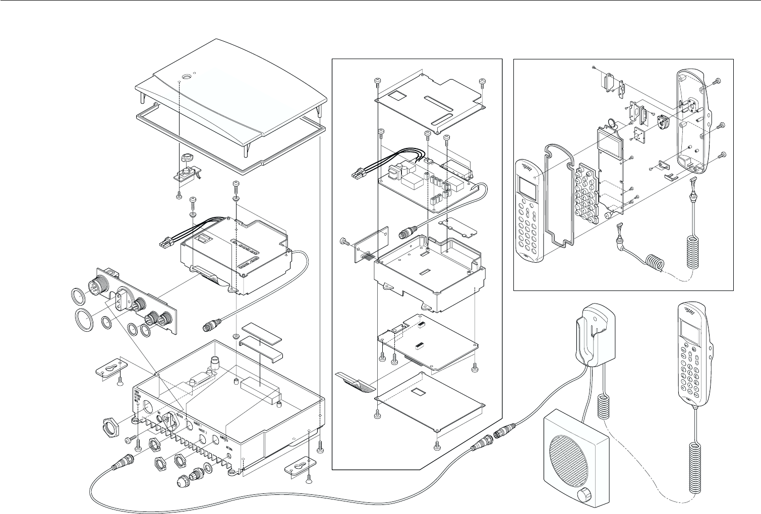
6-12 Parts List and Drawings
6.26.2
6.26.2
6.2 RAY230 ASSEMBLY DRAWINGRAY230 ASSEMBLY DRAWING
RAY230 ASSEMBLY DRAWINGRAY230 ASSEMBLY DRAWING
RAY230 ASSEMBLY DRAWING

6-13
Parts List and Drawings
6.36.3
6.36.3
6.3 BLOCK DIAGRAMBLOCK DIAGRAM
BLOCK DIAGRAMBLOCK DIAGRAM
BLOCK DIAGRAM

6-14 Parts List and Drawings
6.46.4
6.46.4
6.4 RAY230 PCB LAYOUTRAY230 PCB LAYOUT
RAY230 PCB LAYOUTRAY230 PCB LAYOUT
RAY230 PCB LAYOUT
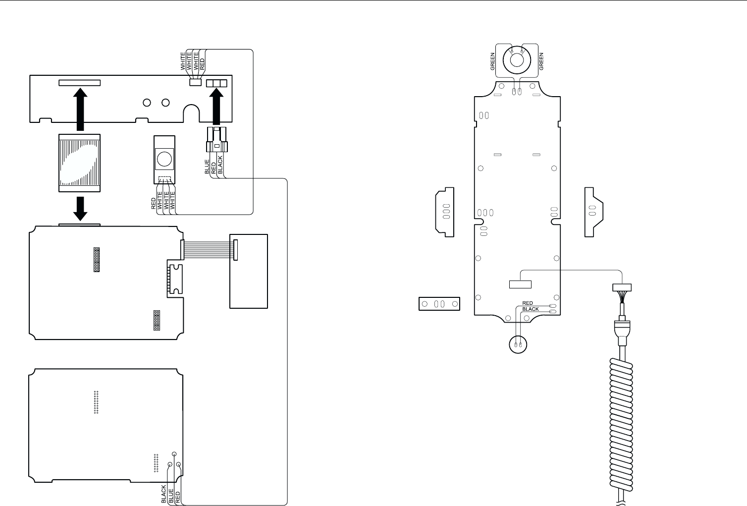
6-15
Parts List and Drawings
6.56.5
6.56.5
6.5 RAY230 WIRING DIAGRAMRAY230 WIRING DIAGRAM
RAY230 WIRING DIAGRAMRAY230 WIRING DIAGRAM
RAY230 WIRING DIAGRAM

6-16 Parts List and Drawings

7-1
Appendix
SECTION 7SECTION 7
SECTION 7SECTION 7
SECTION 7 APPENDIXAPPENDIX
APPENDIXAPPENDIX
APPENDIX
7.17.1
7.17.1
7.1 VHF Marine Channel Usage Guide andVHF Marine Channel Usage Guide and
VHF Marine Channel Usage Guide andVHF Marine Channel Usage Guide and
VHF Marine Channel Usage Guide and
Licensing Requirements Licensing Requirements
Licensing Requirements Licensing Requirements
Licensing Requirements
Most of the information found in this section is reprinted in whole or in
part from FCC information Bulletin No. 2 REVISED EDITION February
1991 and FCC Fact Sheet PR-5000 March 1990.
REMEMBER:
•Maintain a radio watch on Channel 16. Channel 16 is used for distress
and safety purposes only.
•Use VHF Channel 70 only for Digital Selective Calling (DSC). It may be
used for general-purpose calling using DSC. Your cooperation in not
using Channel 70 for general intership communications is necessary to
prevent interference.
•Your VHF transceiver has a high low power switch. Use low power
whenever feasible. Unnecessary high-power operations can interfere with
other important communications.
•Always use your radio call sign at the beginning and end of each
transmission.
•Be sure only qualified persons operate your radio. You are responsible
for control of your radio. Know the rules.
•Limit calls to other vessels to 30 seconds. If you receive no reply, wait 2
minutes; then try again. Keep communications brief and avoid chit-chat.
•Never transmit false distress messages, and never use profanity on the
air.

7-2 Appendix
OTHER REMINDERS:
•You can obtain a station license and call sign by completing FCC Form
605 and mailing it with the required fee to the FCC, Marine Ship Service,
1270 Fairfield Road, Gettysburg, PA 17325-7245.
•You need a radio operator license to operate a VHF Marine Radio only if
you plan to dock in a foreign port or leave a foreign port to dock in a U.S.
port.
•Your radio license is not transferable. If you sell your boat, request the
FCC to cancel your station license.
•If you replace your radio, you do not need to change your license unless
the new radio operates on another frequency band. If you install
equipment to operate on another frequency band, apply for modification
of your license.
•If you carry more than six passengers for hire, your vessel must be certified
as a passenger-carrying vessel by the FCC and the Coast Guard.
7-3
Appendix
Emergency Calling Monitoring Intership Safety
U.S. Coast Guard Navigation Port Operation Noncommercial
Commercial Marine Operator State Control Environmental
Weather
USAGE GUIDEUSAGE GUIDE
USAGE GUIDEUSAGE GUIDE
USAGE GUIDE

7-4 Appendix
Emergency
Channel 16
If:
•Your ship is sinking, or on fire
•Someone has been lost overboard
•There exists grave and imminent
danger
Use this distress procedure:
•Select Channel 16
•Say "Mayday, Mayday, Mayday."
•Give call sign and boat name
•Give location of boat
•Describe emergency
•If no answer, repeat; then try another
channel
Caution
Every ship at sea is to obliged to give
absolute priority to radio
communications relating to ships in
distress - it is vital that false distress
calls or messages not be broadcast.
Calling
Channel 16 & Working Channel
If - you wish to establish
communications with
another station
And - you know which working
channel the station is
monitoring
Then - initiate the call directly on
that working channel
If - you wish to establish
communications with
another station
And - you do not know what
working channel the
station may be monitoring
Then - initiate the call on channel
16. After contact is made
switch to a working
channel.
Note: Due to congestion on channel
16 caused by frequent hailing
of other vessels, the FCC has
approved channel 9 as a second
hailing channel.
Avoid excessive calling and radio
checks
Always monitor before transmitting
Never interrupt emergency
communications

7-5
Appendix
Monitoring
Channel 16 & Working Channel
When - your VHF station is turned
on and it is not being used
to exchange
communications
You Must - monitor channel 16
As an operating convenience, many
stations employ a second receiver so
that they can monitor a working
channel and channel 16 simultaneously.
Intership Safety
Channel: 6
Vessels: Any
Use: Communicating
navigational and weather
warnings to other ships
Communicating with U.S. Coast Guard
stations or other vessels during search
and rescue operations
Between: Ship-to-ship only
Comments: Do not use for routine
communications. This is a
safety channel.

7-6 Appendix
U.S. Coast Guard
Channel: 22
Vessels: Any
Use: Working channel for
exchange of
communications with
stations of the U.S. Coast
Guard.
Between: Ship to U.S. Coast Guard
ship, coast to aircraft
stations
Comments: U.S. Coast Guard does not
regularly monitor this
channel. Establish contact
on channel 16 and shift to
channel 22 as directed.
Navigation
Channel: 13
Vessels: Any
Use: Safety Communications
pertaining to the
maneuvering of vessels or
the directing of vessel
movements
Ship-to ship and secondarily ship-to-
coast
This is commonly called the Bridge-to-
Bridge channel. Large vessels and
towboats depend on this channel for
their safe navigation. Railway or
highway bridges which open for ship
navigation often operate on this
channel.
Bridge-to-Bridge stations must reduce
power to one watt for routine
operations.

7-7
Appendix
Port Operations
Channels: 5, 12, 14, 20, 65, 66, 73, 74
[77]
Vessels: Any
Use: Messages relating to the
operational handling,
movement and safety of
vessels in or near ports,
locks and waterways.
Between: Ship-to ship or ship-to-
coast
Comments: Channel 77 is limited to
communications to and
from commercial pilots
concerning the movement
and docking of vessels.
Note: Channels 11, 12, 13 and 14
are used for vessels traffic
service on the Great Lakes,
St. Lawrence Seaway and
designated major ports.
Non commercial (Boat Operations)
Channels: 19, 68, 69, 71, 72, 78
Vessels: Recreational boats and any
others not used primarily
for commercial transport.
Use: Communications
pertaining to the needs of
the vessel (i.e., fishing,
rendezvous, maneuvers,
berthing, scheduling of
repairs, provisioning, etc.)
Between: Ship-to-ship or ship to
limited coast stations
Comments: Channel 72 may not be
used for ship to coast
communications. Channel
9 is shared with
Commercial users.
If you regularly monitor one of these
channels with a second receiver, please
notify frequently-called stations of this
practice. Help reduce congestion on
channel 16.

7-8 Appendix
Commercial
Channels: 7, 8, 9, 10, 11, 18, 19, 67, 79,
80, [88]
Vessels: Those used primarily for
commercial transport of
persons or goods, or
engaged in servicing other
vessels
Use: Communications
pertaining to the purpose
for which the vessel is
used
Between: Commercial transport
vessels (ship-to-ship) or
between commercial
transport vessels and
limited coast stations
Channel 8, 67 and 88 may not be used
for ship-to-coast communications
Recreational boats are not permitted to
use these channels
Channel 88 not available on Great Lakes
and St. Lawrence Seaway.
Marine Operator
Channels: 24, 25, 26, 27, 28, 84, 85, 86,
87, 88
Vessels: Any
Use: To place a telephone call to
any location in the world
or to a vessel outside of
your transmitting range
Between: Vessels and public coast
stations
Comments: Contact the marine
operator on the channel
assigned to your
navigating area. If unable
to determine this channel,
use channel 16.
Be patient. Do not interrupt calls in
progress. Avoid excessive calling if the
operator does not answer - give the
operator a chance to reply.

7-9
Appendix
State Control
Channel: 17
Vessels: State and local government
Use: Coordination, regulation
and control of boating
activities and the rendering
of assistance to vessels.
Between: Ship and coast stations
associated with state and
local governments.
Environmental
Channel: 15
Vessels: Any (receive only)
Use: Broadcast of information
concerning the
environmental conditions
in which vessels operate -
weather, sea conditions,
time signals, notices to
mariner, hazards to
navigation
Between: One-way broadcast from
coast to ship stations
Note: Currently used for Class C
EPIRB emergency signals.

7-10 Appendix
Weather
Channels: WX1, WX2, WX3
Vessels: Any
Use: Continuous weather
information from NOAA
(National Oceanic and
Atmospheric
Administration)
Between: One-way broadcast from
NOAA to any interested
parties
Comments: Receive only. You are not
allowed to transmit on
these frequencies.

7-11
Appendix
PHONETIC ALPHABET:PHONETIC ALPHABET:
PHONETIC ALPHABET:PHONETIC ALPHABET:
PHONETIC ALPHABET:
To help make call letters more clearly understood, and to assist in spelling
out similar sounding or unfamiliar words, radiotelephone users employ the
international phonetic alphabet.
Phonetic Alphabet:
A - ALPHA
B - BRAVO
C - CHARLIE
D - DELTA
E - ECHO
F - FOX-TROT
G - GOLF
H - HOTEL
I - INDIA
J - JULIET
K - KILO
L - LIMA
M - MIKE
N - NOVEMBER
O - OSCAR
P-PAPA
Q - QUEBEC
R - ROMEO
S - SIERRA
T - TANGO
U - UNIFORM
V - VICTOR
W - WHISKEY
X - X-RAY
Y - YANKEE
Z - ZULU

7-12 Appendix