Flir BelgiumBA RAY49 VHF/FM Marine Transmitter with Class D DSC User Manual 81296 1www
Raymarine UK Ltd. VHF/FM Marine Transmitter with Class D DSC 81296 1www
UserManual.wiki
>
Flir BelgiumBA
>
RAY49 User Manual
>
User handbook Part 1
Contents
1.
User handbook Part 1
2.
User handbook Part 2
User handbook Part 1
Navigation menu
Upload a User Manual
Namespaces
Wiki Guide
HTML
PDF
Info
Views
User Manual
Discussion / Help
Navigation

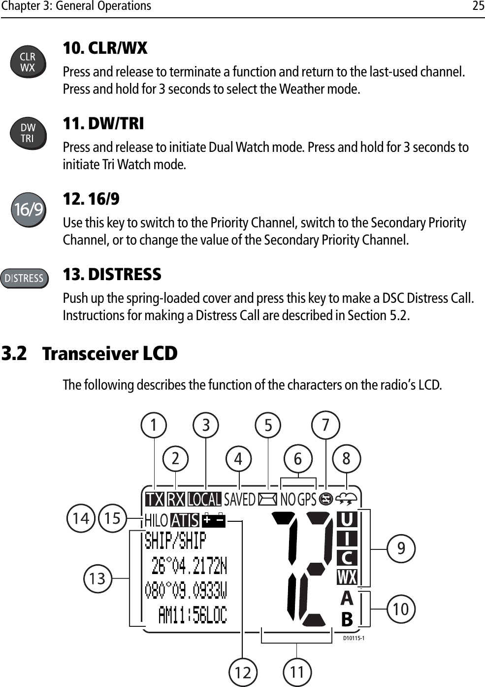
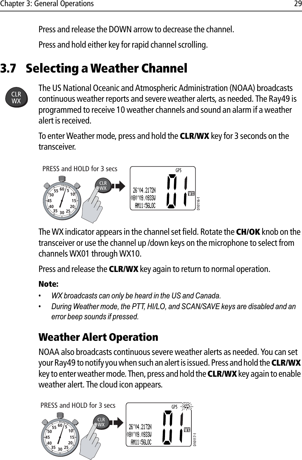
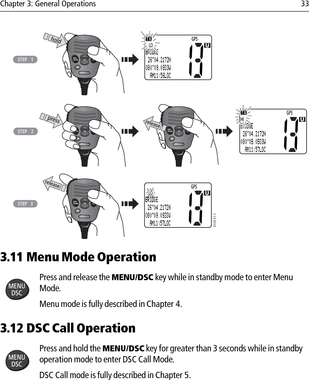
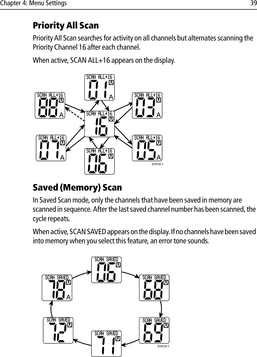
![Chapter 3: General Operations 31Reprograming Secondary Priority Channel1. Press and hold the 16/9 key for 3 seconds to switch to the current Secondary Priority Channel. 2. Press and hold the 16/9 key for 3 seconds again to switch to Reprogram mode. The message CHG 2ND PRI? appears with YES highlighted. 3. Press the CH/OK knob to accept. The confirmation message CHANGE 2ND PRIORITY CH appears.4. Rotate the CH/OK knob until the desired new secondary channel is shown.5. Press CH/OK to accept the new Secondary Priority selection. 10152025303540455055 60 510152025303540455055 60 5D10120-1CH 2ND PRI?>YESNO2ND PRIORITY 26 04.2172N080 09.0933W AM11:56LOCSELECT 2NDPRIORITY CHPRESS [OK]TO ACCEPTSELECT 2NDPRIORITY CHPRESS [OK]TO ACCEPT2ND PRI CHIS CHANGEDPRESS [OK]2ND PRIORITY 26 04.2172N080 09.0933W AM11:57LOC](https://usermanual.wiki/Flir-BelgiumBA/RAY49.User-handbook-Part-1/User-Guide-840092-Page-31.png)
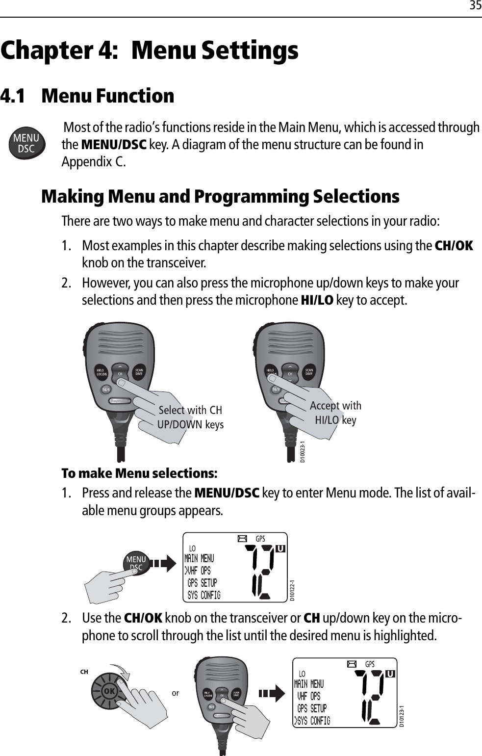
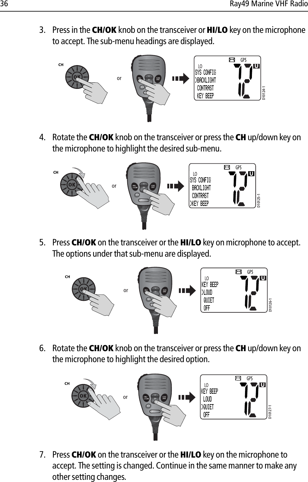
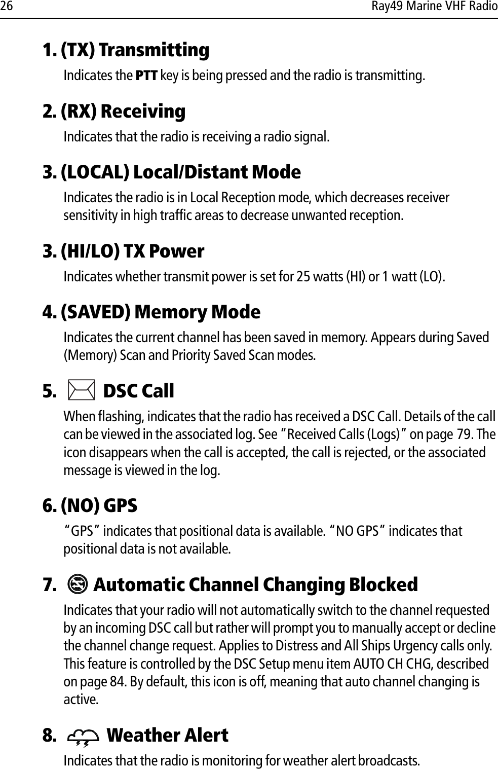
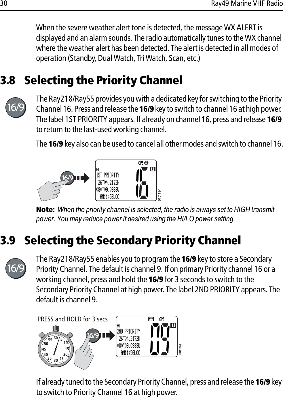
![Chapter 4: Menu Settings 37 To return to the previous menu level, select the [BACK] menu option or press the CLR/WX key.To exit the Menu mode, press the CLR/WX key again or else press the 16/9 key to switch to the priority channel in standby mode.4.2 VHF OperationsThis menu group controls basic radio functions. You access VHF Operations via the MENU key. Scan ModeThis function automatically searches through all channels in the set for any that are broadcasting. If a transmission is received, the scan stops on the receiving channel as long as it is present. If the signal is lost for five seconds, the radio resumes scanning.You can directly access the Scan Mode menu by pressing and releasing the SCAN/SAVE key on the microphone. When a Scan Mode is active, you can terminate the scan and return the radio to standby mode by pressing and releasing the key again.While scanning, press the microphone CH up/down keys or rotate the CH/OK knob on the transceiver to change the scan direction. UP (key)/clockwise (CHknob) increases the channel while DOWN (key) /counter-clockwise (CH knob) decreases it.D10128-1SYS CONFIG BACKLIGHT CONTRAST>KEY BEEPD10129-1MAIN MENU>VHF OPS GPS SETUP SYS CONFIGVHF OPS>SCAN MODE HI/LO POWER SAVE CH](https://usermanual.wiki/Flir-BelgiumBA/RAY49.User-handbook-Part-1/User-Guide-840092-Page-37.png)
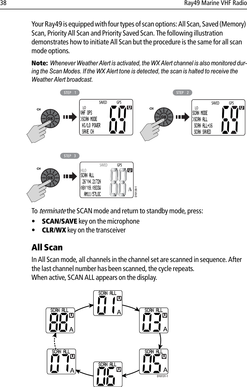
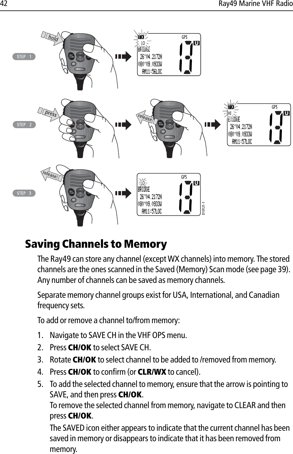
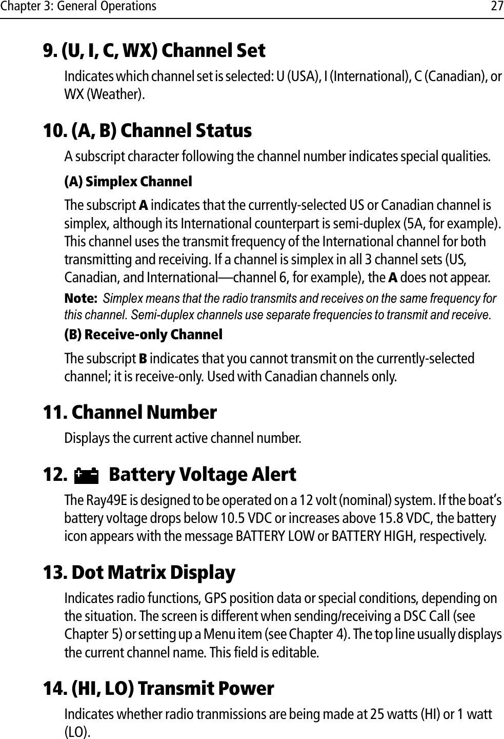
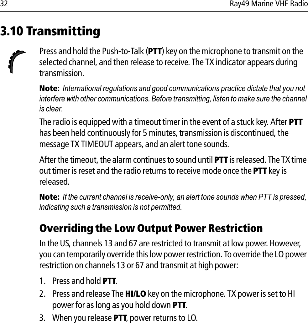
![Chapter 4: Menu Settings 43 You can also add the current channel to memory by pressing and holding the SCAN/SAVE key on the microphone. If the channel is already saved, pressing and holding the key removes the channel from memory.Using the Watch ModesThe Watch Modes monitor the programmed Priority Channel and other user-selected channel(s). The watch is halted when activity is detected on a monitored channel. The Ray49 is equipped with 2 types of monitor operations: Dual Watch and Tri Watch.Note:Whenever Weather Alert is activated, the WX Alert channel is also monitored dur-ing Dual Watch and Tri Watch. D10136-1SAVE CHANNELSELECT CH[OK] / [CLR]72VHF OPS SCAN MODE HI/LO POWER>SAVE CH68SAVE CHANNELSELECT CH[OK] / [CLR]68SAVE CHANNELSELECT CH[OK] / [CLR]72SAVE CHANNEL>SAVE CLEAR72](https://usermanual.wiki/Flir-BelgiumBA/RAY49.User-handbook-Part-1/User-Guide-840092-Page-43.png)
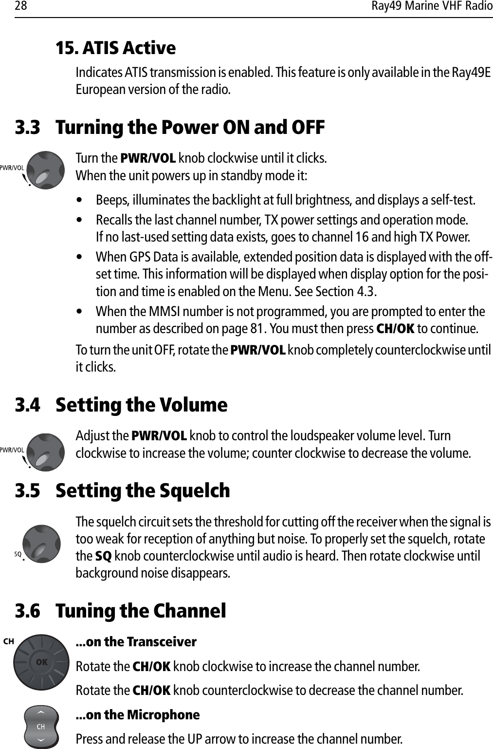
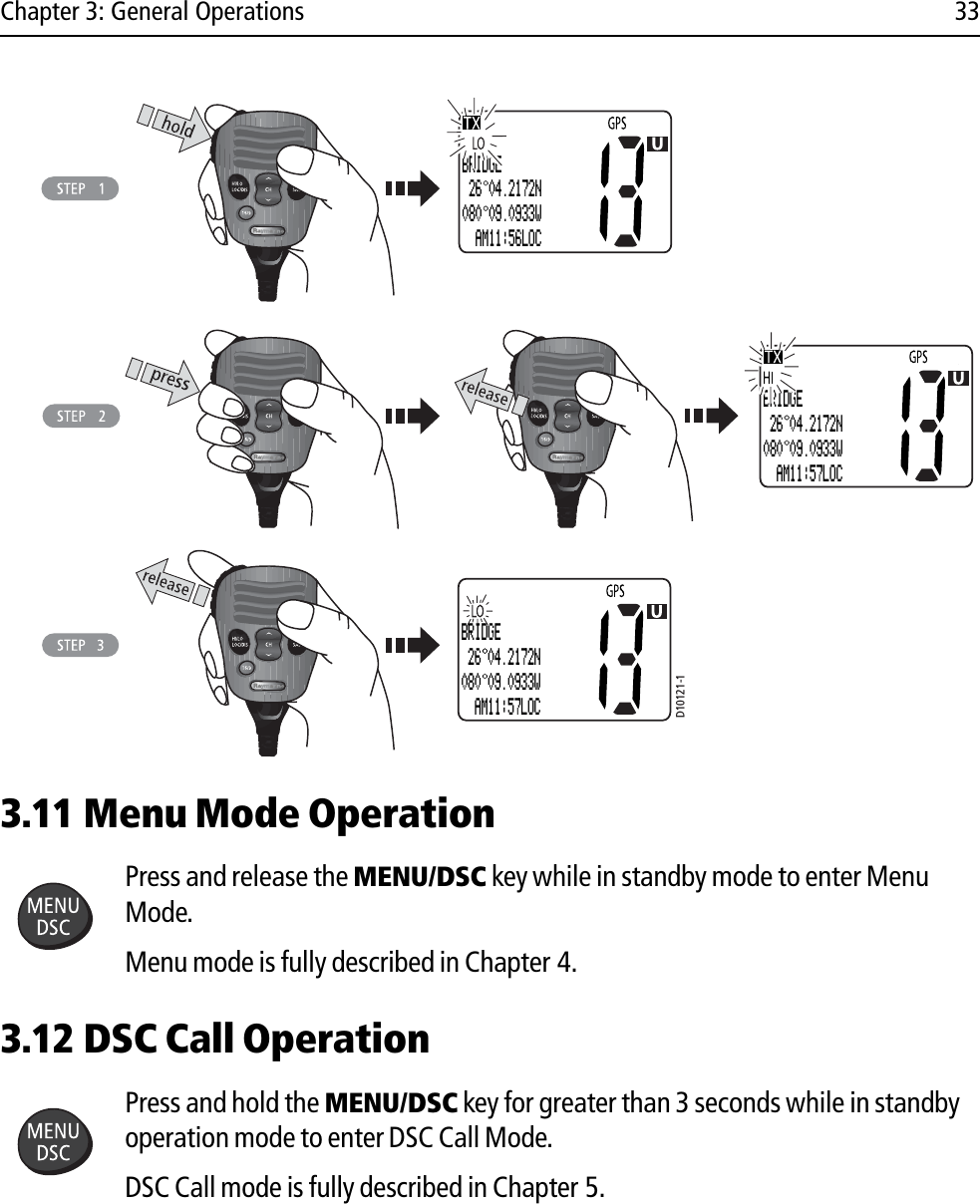
![44 Ray49 Marine VHF RadioDual WatchDual Watch monitors the current working channel and Channel 16 in cycle.DUAL 16 appears on the top line of the display.Dual Watch is demonstrated in the figure to the left; the sample working channel is channel 72. Tri WatchTri Watch monitors in cycle channel 16, the current working channel and the channel you have set as the Secondary Priority Channel.TRI 16+09 appears on the top line of the display.Tri Watch is demonstrated in the figure to the left; the sample working channel is channel 72. Press and release the 16/9 key to terminate Watch mode and switch to the Priority Channel.Press and release the CLR/WX key to terminate Watch mode and return to the last-used channel.Note: During Tri Watch Mode, the WX and CH keys are inactive and an error beep sounds if pressed (if the Key Beep function is enabled). D10138-1D10139-1D10137-1VHF OPS HI/LO POWER SAVE CH>WATCH MODE72WATCH MODE>DUAL WATCH TRI WATCH [BACK]72WATCH MODE DUAL WATCH>TRI WATCH [BACK]72TRI CH16+09 26 04.2172N080 09.0933W PM12:32LOC72](https://usermanual.wiki/Flir-BelgiumBA/RAY49.User-handbook-Part-1/User-Guide-840092-Page-44.png)
![46 Ray49 Marine VHF RadioTo completely remove the Channel Name, rotate the CH/OK knob to choose DELETE in step 5 above, instead, and then press CH/OK to select. After the name is deleted, no name is displayed for this channel. D10141-1VHF OPS WATCH MODE FREQ BAND>CH NAME72CH NAMESELECT CH[OK] / [CLR]72SAVE CHANNELSELECT CH[OK] / [CLR]68CH NAME>EDIT DELETE68EDIT NAMEPLEASUREHOLD [OK]68EDIT NAMEFLEASUREHOLD [OK]6868EDIT NAMEFISHINGHOLD [OK]68FISHING 26 04.2172N080 09.0933W AM11:57LOC10152025303540455055 60 5](https://usermanual.wiki/Flir-BelgiumBA/RAY49.User-handbook-Part-1/User-Guide-840092-Page-46.png)
![Chapter 4: Menu Settings 49 SettingsYou can also set how some time and position information is displayed on the screen. Make your selection from the options on the list. GPS SETUP>MANUAL POS SETTING [BACK]09MANUAL POS _-- --.----N --- --.----W --:--UTC09MANUAL POS 2- --.----N --- --.----W --:--UTC09MANUAL POS 26 04.2100N -- --.----W --:--UTC09MANUAL POS 26 04.2100N 0-- --.----W --:--UTC09 09MANUAL POS 26 04.2100N080 09.0900W _-:--UTCMANUAL POS 26 04.2100N 080 09.0900W 1-:--UTC09D10147-109CALLING 26 04.2100N080 09.0900W MAN10:00UTCD10148-1GPS SETUP MANUAL POS>SETTING [BACK]09 09SETTING>L/L DISPLAY TIME DISPLY TIME OFFSET](https://usermanual.wiki/Flir-BelgiumBA/RAY49.User-handbook-Part-1/User-Guide-840092-Page-49.png)
![Chapter 4: Menu Settings 51 Note:If COG/SOG is set ON, TIME DISPLAY is automatically set to OFF. Because they occupy the same line on the LCD, only one of these two settings can be displayed at a time.NMEA OutWhen Distress Call and Position (lat/lon) information is received from other stations, your Ray49 has the capability of forwarding this data to your display unit over the NMEA port so that it can be displayed on the screen. You can specify whether this option is ON or OFF.4.4 System Configuration Use these menu items for selecting general system-wide settings. Backlight AdjustmentThis setting adjusts the backlight brightness for the LCD, microphone keypad and transceiver keypad. Choose from 10 brightness settings or OFF.Rotate the CH/OK knob or use the microphone up/down arrow keys to select the desired backlight level. The number of blocks illuminated in the bar indicates the level, one through ten. For HI all 10 are illuminated; for OFF none are illuminated. D10149-171SETTING TIME FORMAT>COG/SOG [BACK]71COG/SOG>ON OFF[BACK]71PLEASURE 26 04.2172N080 09.0933W111'T 12.4KTD10150-1MAIN MENU>VHF OPS GPS SETUP SYS CONFIG09MAIN MENU VHF OPS GPS SETUP>SYS CONFIG09](https://usermanual.wiki/Flir-BelgiumBA/RAY49.User-handbook-Part-1/User-Guide-840092-Page-51.png)
![52 Ray49 Marine VHF RadioPress the transceiver CH/OK knob or microphone HI/LO key to accept. Contrast AdjustmentThis setting adjusts the levels of LCD contrast. Choose from 10 settings. Rotate the CH/OK knob to select the desired contrast level. The number of blocks illuminated in the bar indicate the level. A larger number of blocks indicate a darker LCD. For HI, all 10 blocks are illuminated; for LO none are illuminated. D10151-1SYSTM CONFIG>BACKLIGHT CONTRAST KEY BEEP69BACKLIGHTOFF HIPRESS [OK]69BACKLIGHTOFF HIPRESS [OK]69SYSTM CONFIG>BACKLIGHT CONTRAST KEY BEEP69D10152-1CONTRASTLO HIPRESS [OK]71SYSTM CONFIG BACKLIGHT>CONTRAST KEY BEEP71CONTRASTLO HIPRESS [OK]71SYSTM CONFIG BACKLIGHT>CONTRAST KEY BEEP71](https://usermanual.wiki/Flir-BelgiumBA/RAY49.User-handbook-Part-1/User-Guide-840092-Page-52.png)
![Chapter 4: Menu Settings 53Key BeepThis setting is used to set the volume of the beep that sounds when a key is pressed. Select LOUD, QUIET or OFF. Bearing ModeThis setting is used to determine how heading data are displayed when COG/SOG is displayed (see page 50). Select MAGNETIC or TRUE. If you select MAGNETIC, an “M” appears. If TRUE is selected, a “T” appears. D10153-1SYSTM CONFIG BACKLIGHT CONTRAST>KEY BEEP09KEY BEEP>LOUD QUIET OFF0909KEY BEEP LOUD>QUIET OFFSYSTM CONFIG BACKLIGHT CONTRAST>KEY BEEP09D10154-1SYSTM CONFIG CONTRAST KEY BEEP>BEARING MOD16BEARING MODE>TRUE MAGNETIC [BACK]1616BEARING MODE TRUE>MAGNETIC [BACK]16DISTRESS 26 04.2172N080 09.0933W111 M 12.4KT](https://usermanual.wiki/Flir-BelgiumBA/RAY49.User-handbook-Part-1/User-Guide-840092-Page-53.png)
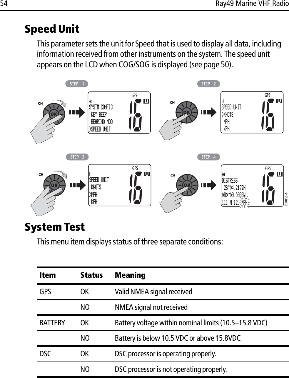
![Chapter 4: Menu Settings 55 Version NumberThis menu item displays the hardware and software versions of your radio. ResetUse this menu item to return your radio to the default factory settings. The following items are reset. All other settings are unaffected. D10156-1SYSTM CONFIG BEARING MOD SPEED UNIT>SYSTEM TEST16SYSTEM TESTGPS: OKBATTERY: OKDSC: OK16D10157-1SYSTM CONFIG SPEED UNIT SYSTEM TEST>VERSION09VERSIONSOFT: 2.19HARD: _.__PRESS [OK]09D10158-168SYSTM CONFIG SYSTEM TEST VERSION>RESETSYSTM CONFIG SYSTEM TEST VERSION>RESET68SYSTEM RESET>YES NO [BACK]68](https://usermanual.wiki/Flir-BelgiumBA/RAY49.User-handbook-Part-1/User-Guide-840092-Page-55.png)