Flir BelgiumBA RAY54 VHF/FM marine transceiver with class D DSC User Manual 81231 1
Raymarine UK Ltd. VHF/FM marine transceiver with class D DSC 81231 1
UserManual.wiki
>
Flir BelgiumBA
>
RAY54 User Manual
>
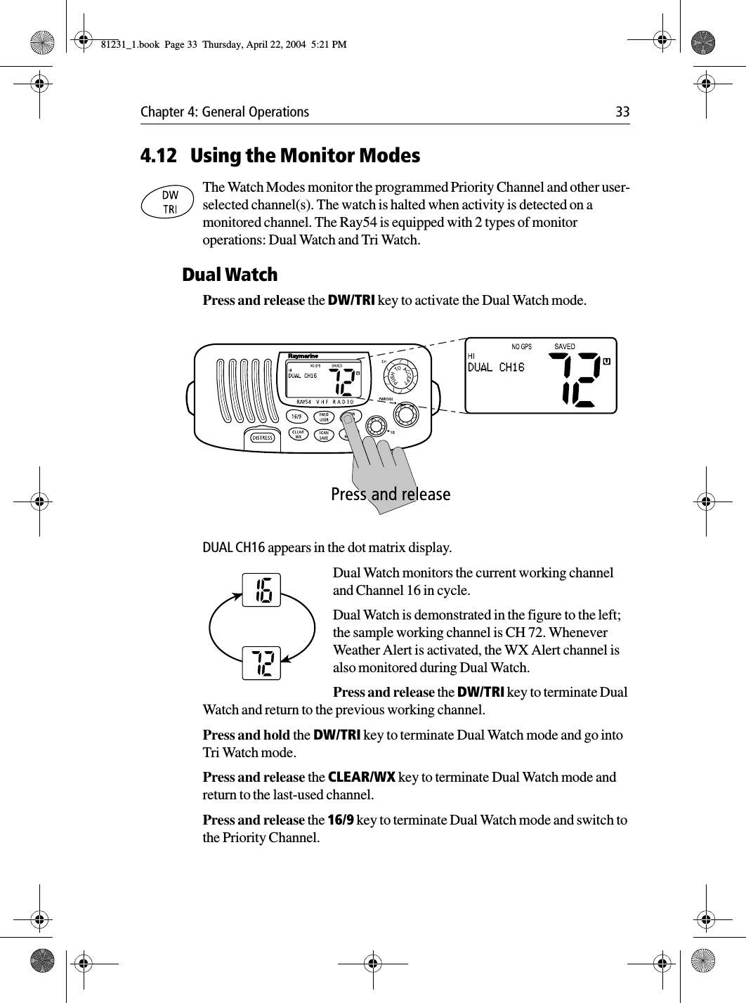
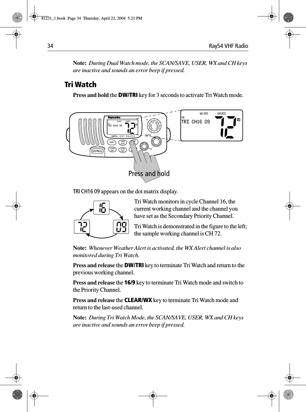
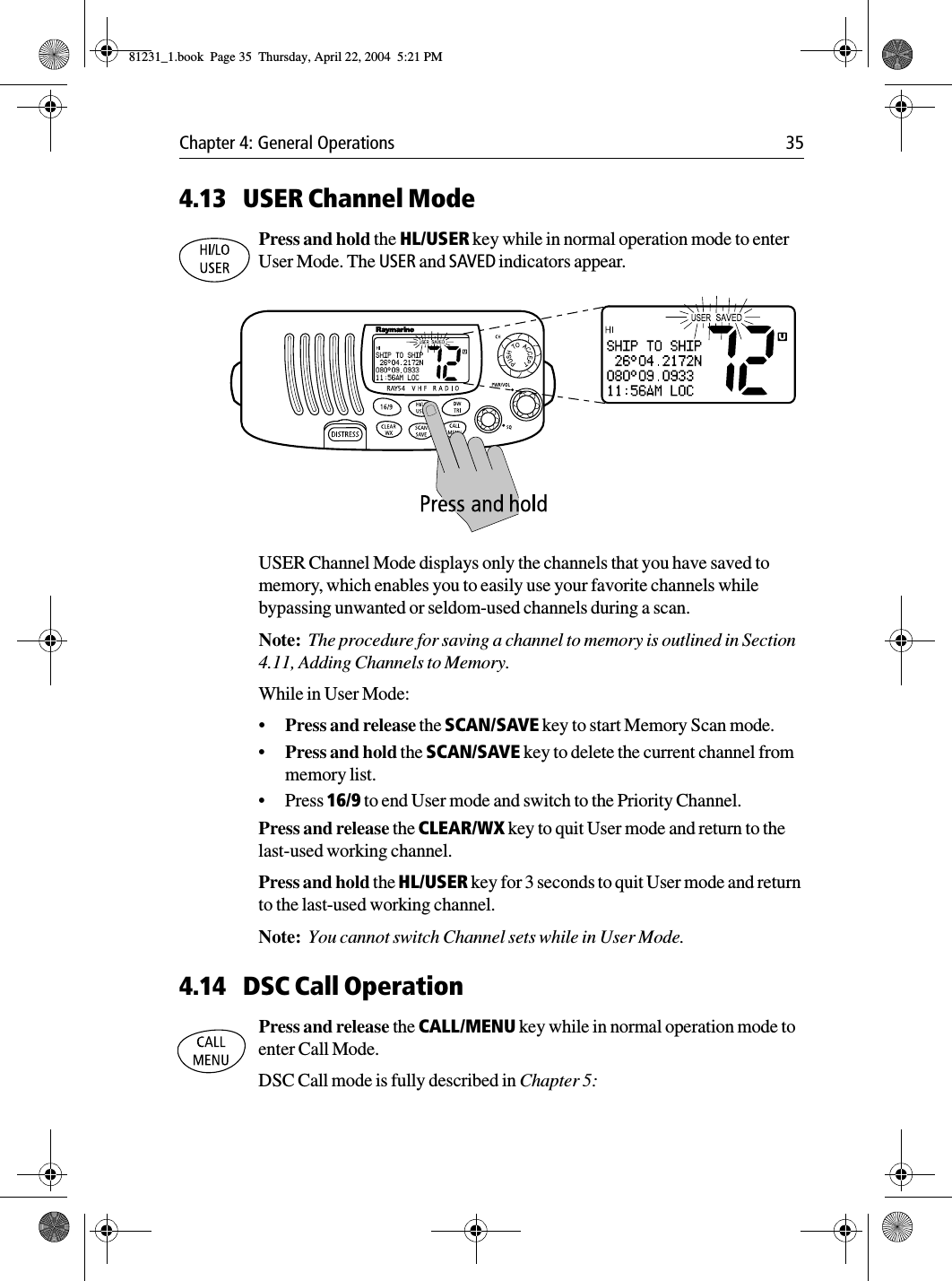
Owner handbook 1
Contents
1.
Owner handbook 1
2.
Owner handbook 2
3.
Owner handbook 3
Owner handbook 1
Navigation menu
Upload a User Manual
Namespaces
Wiki Guide
HTML
PDF
Info
Views
User Manual
Discussion / Help
Navigation