Flir BelgiumBA S1000 S1000 Autopilot with radio interface node User Manual Logo World Leaders B W 38mm eps
Raymarine UK Ltd. S1000 Autopilot with radio interface node Logo World Leaders B W 38mm eps
Contents
- 1. Installation Manual
- 2. Operation Manual
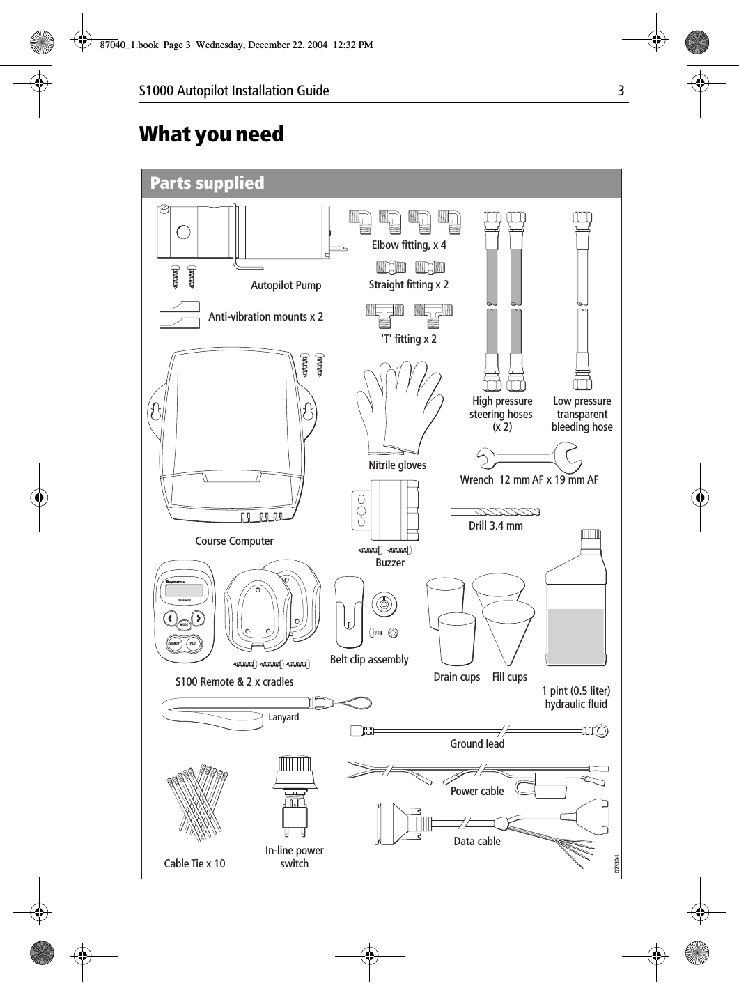
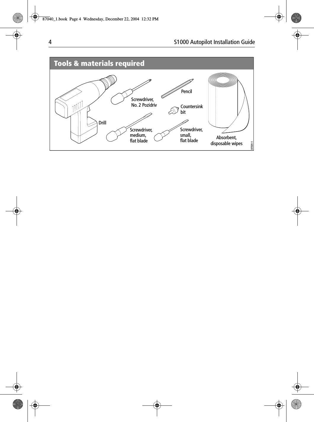
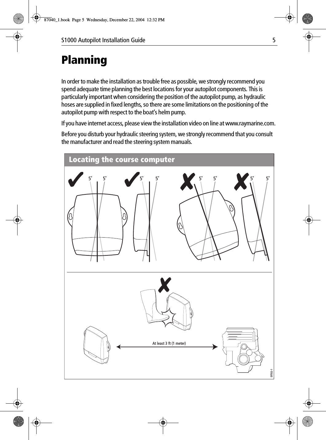
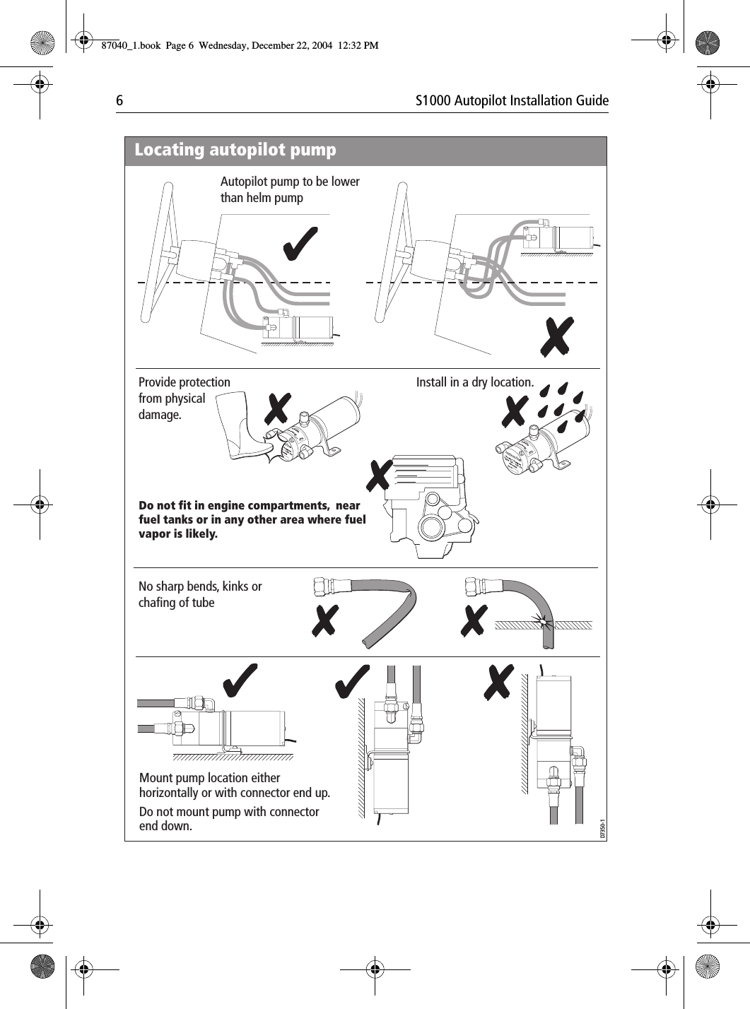
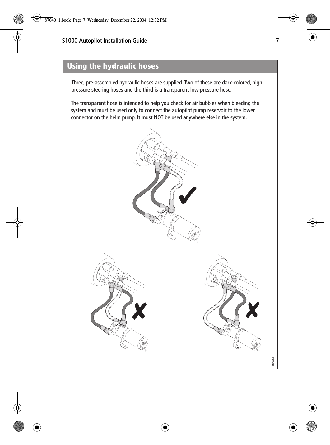
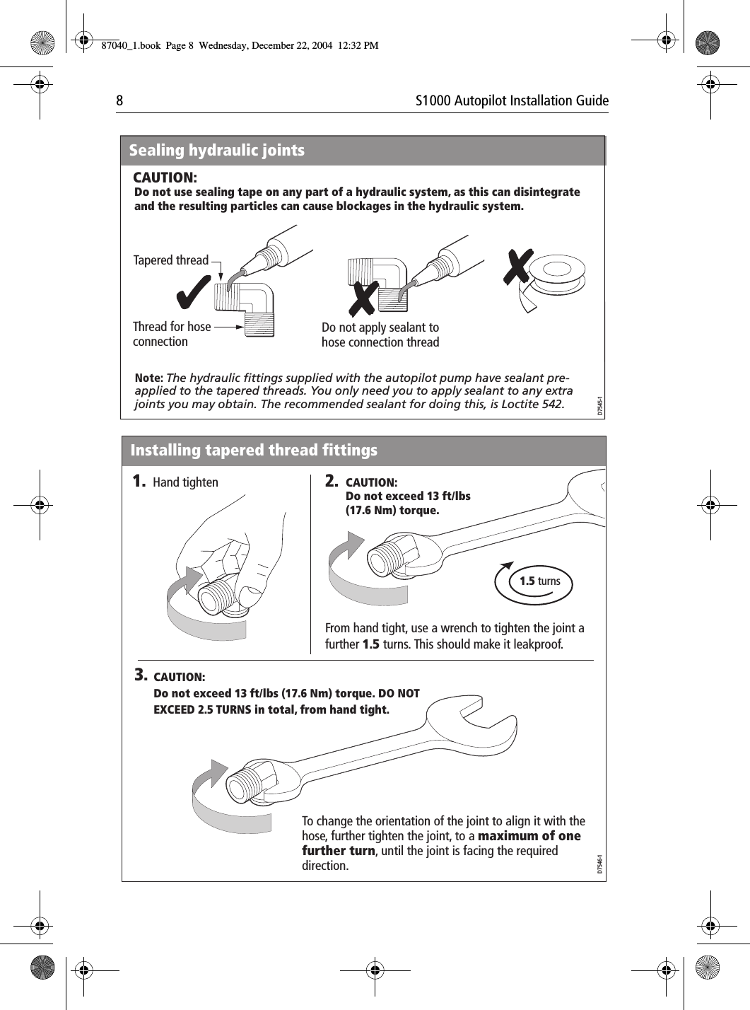
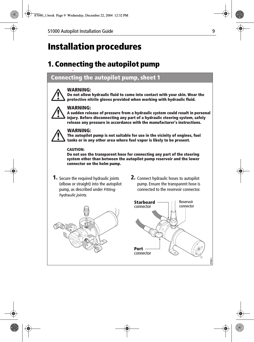
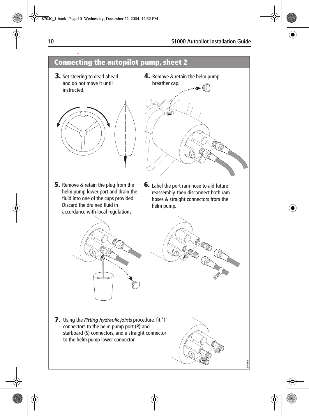
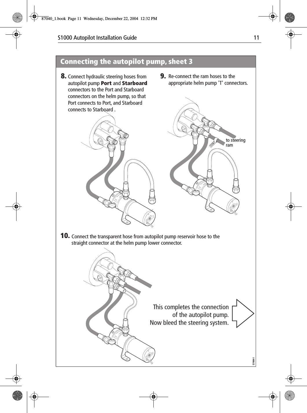
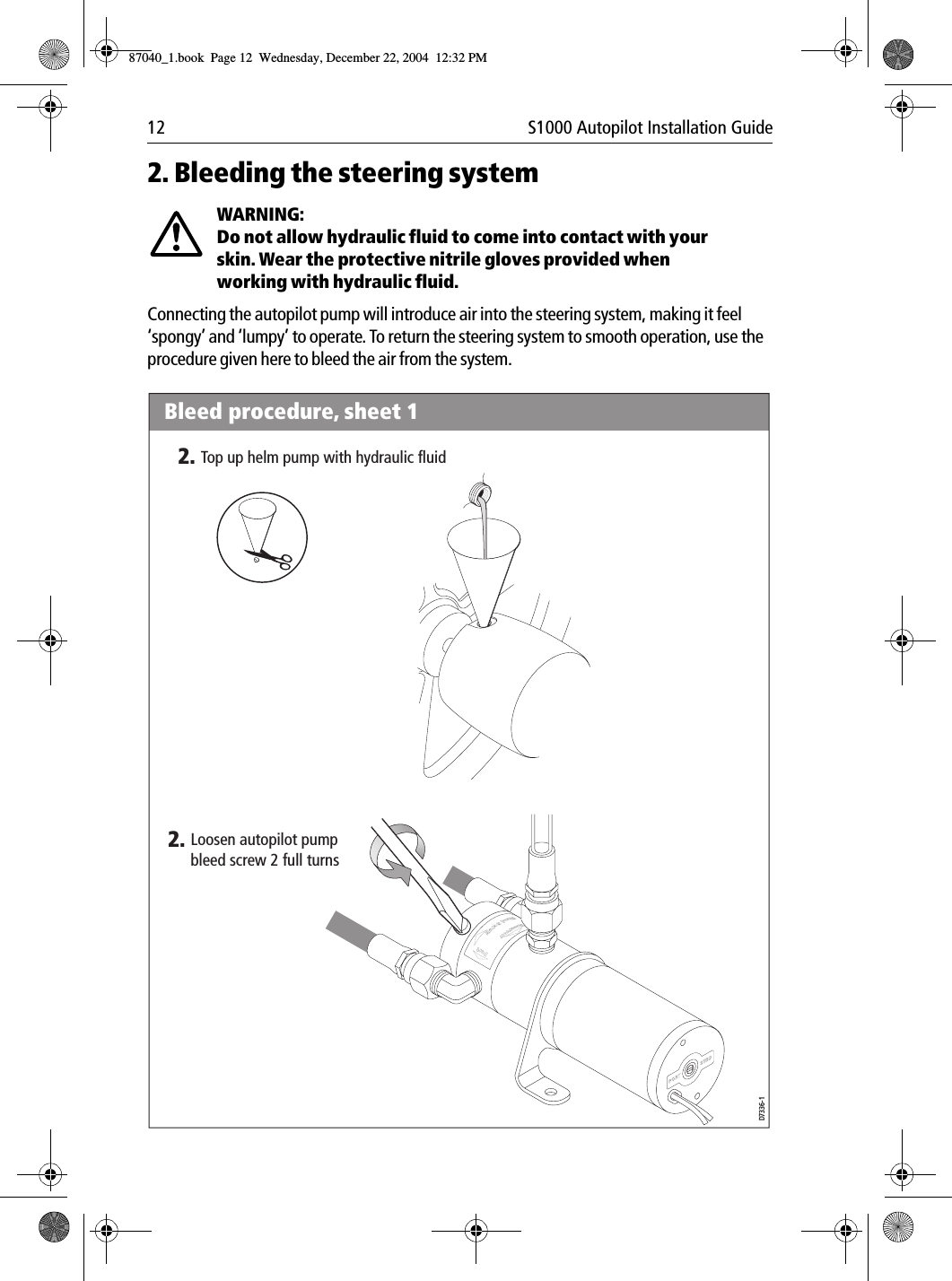
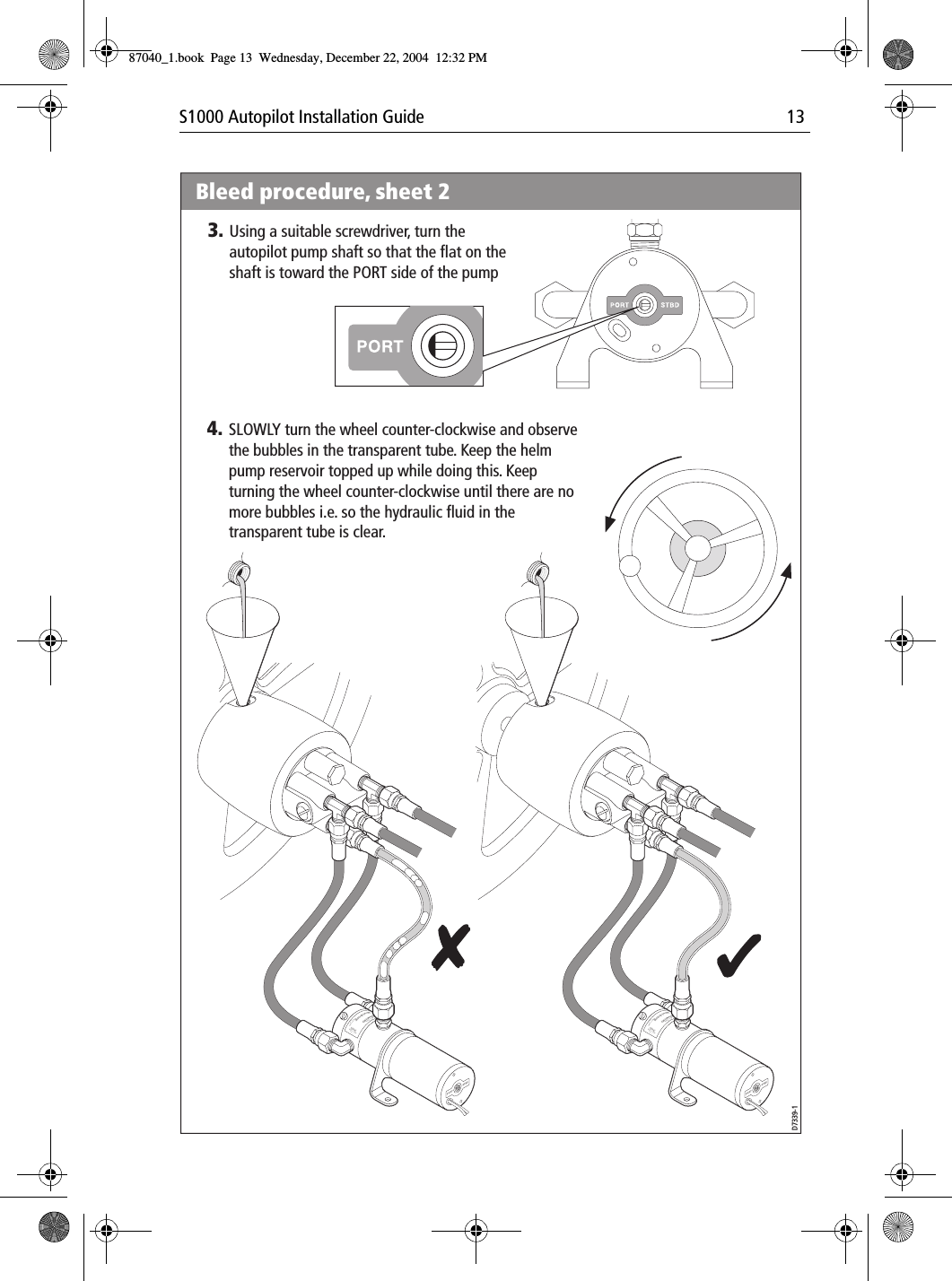
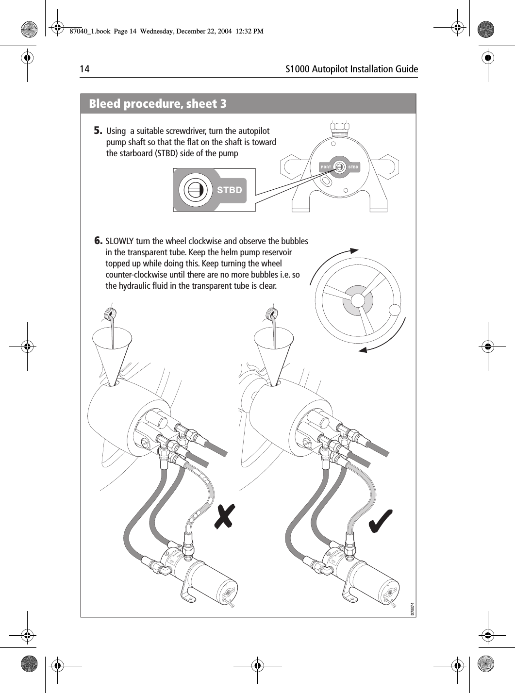
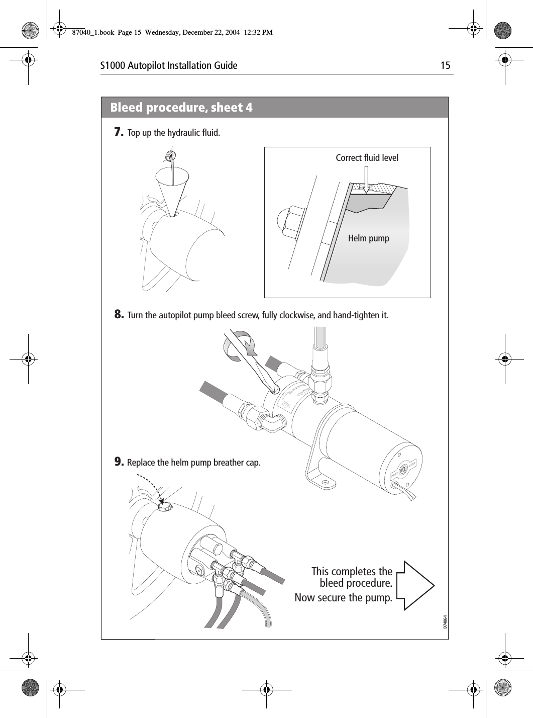
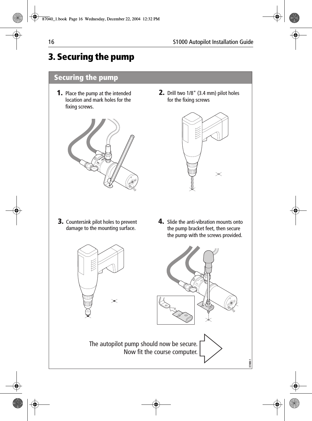
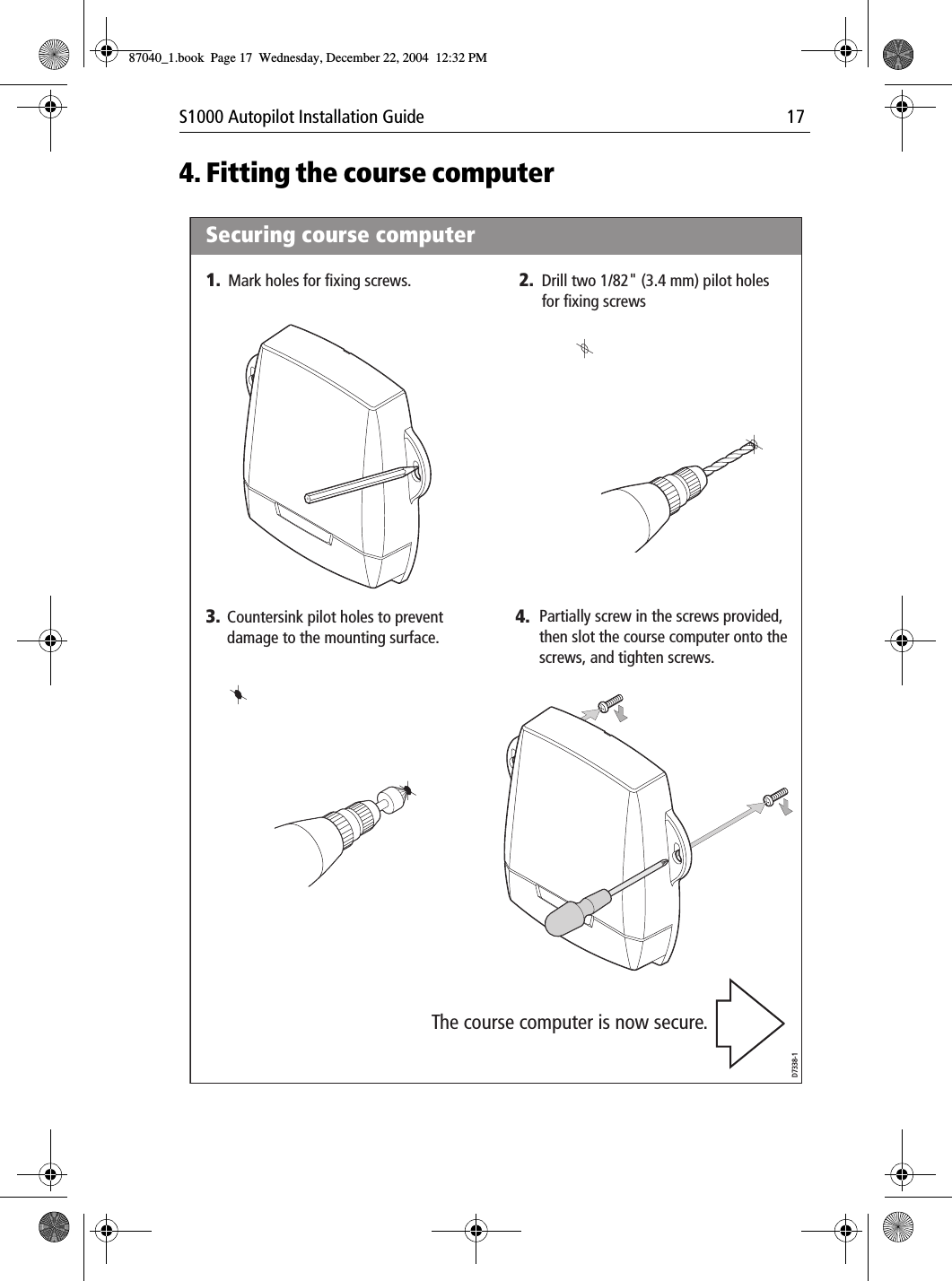
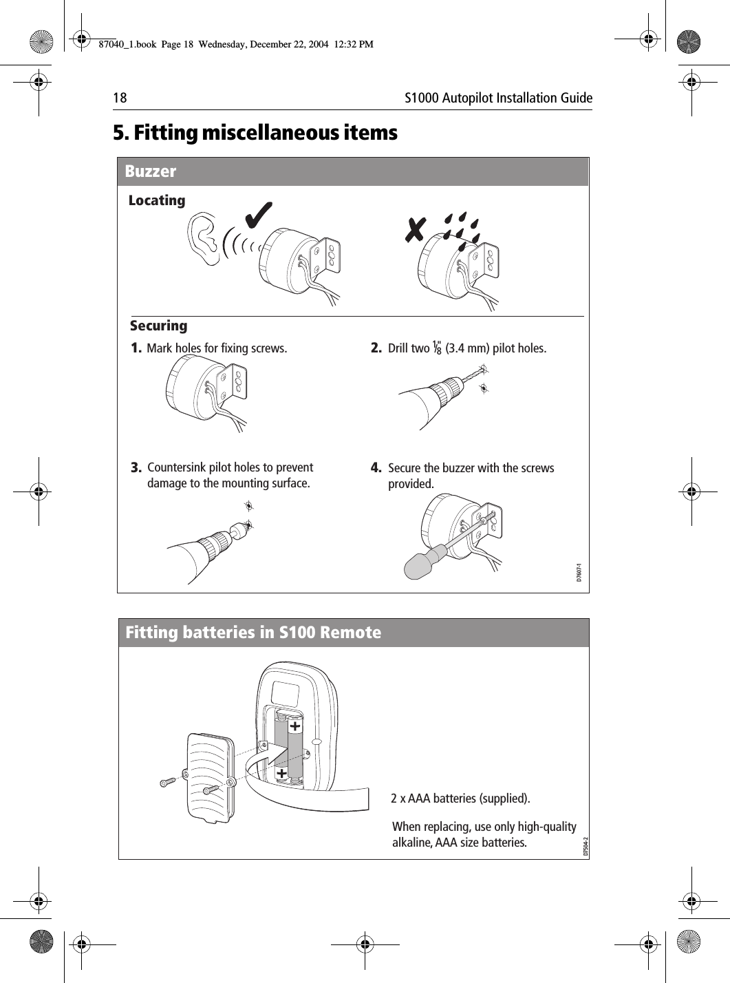
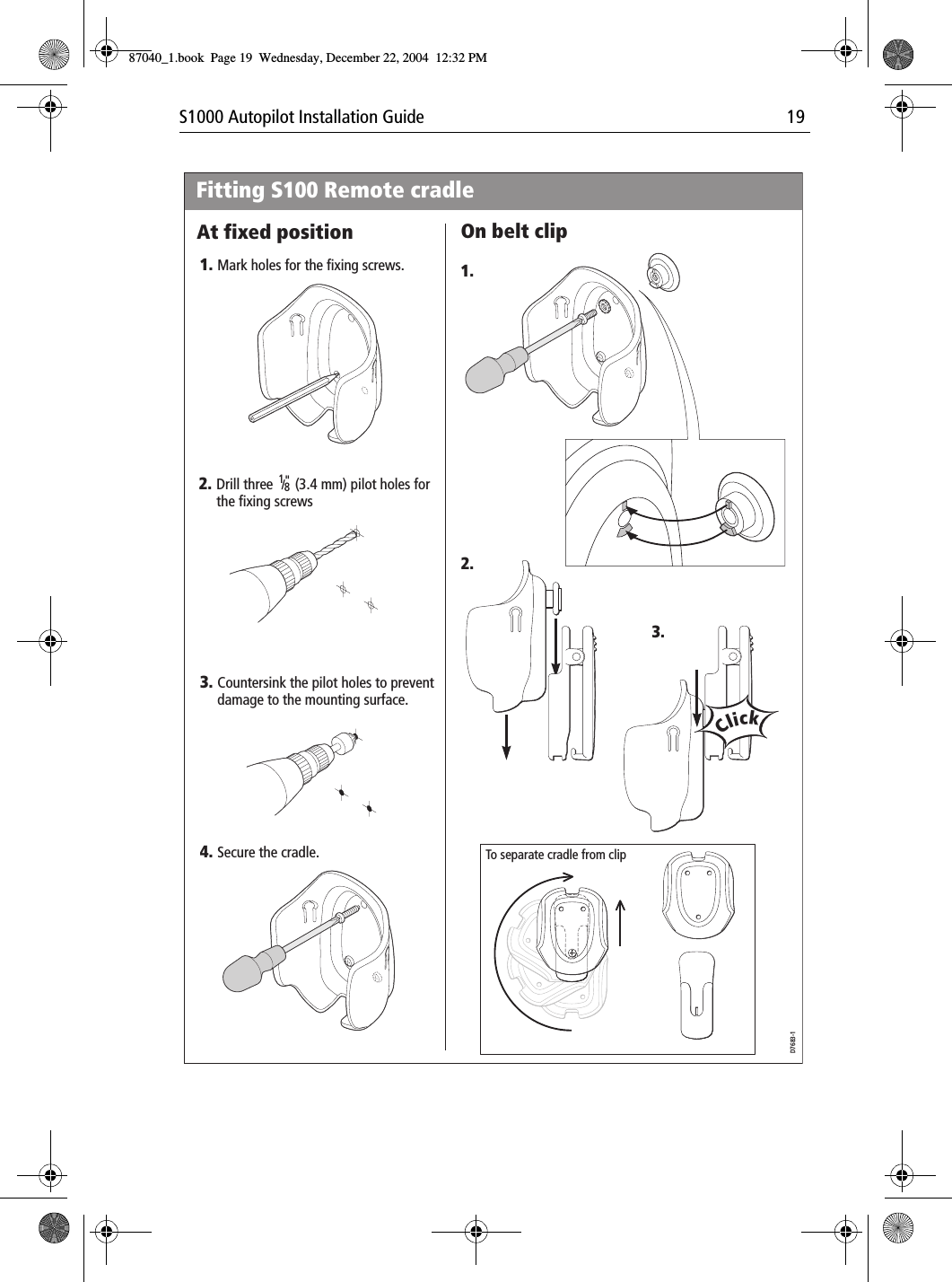
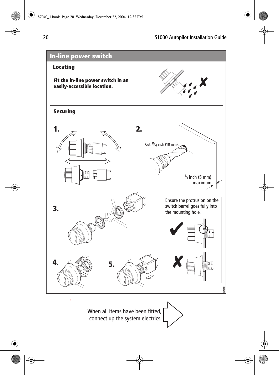
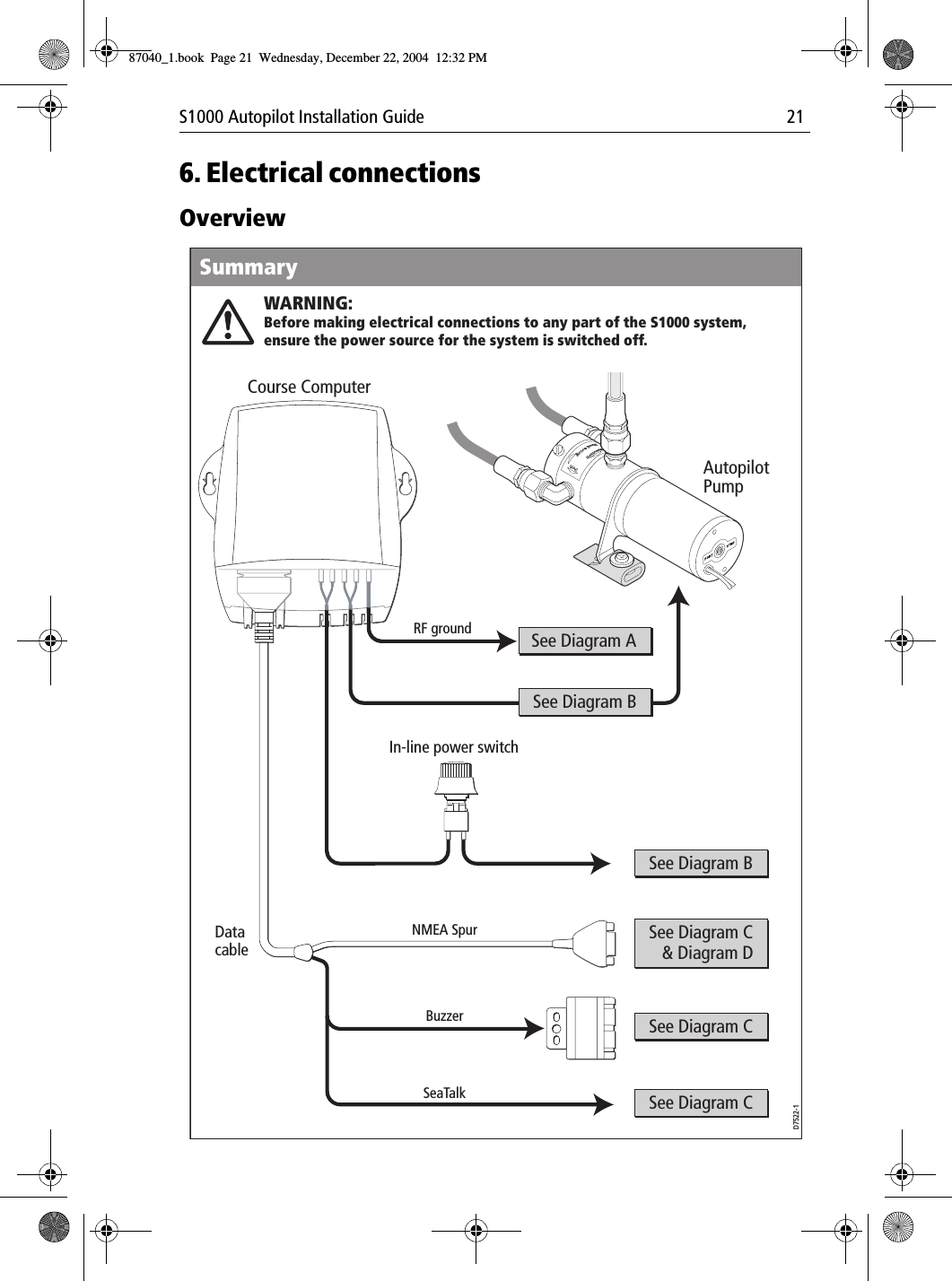
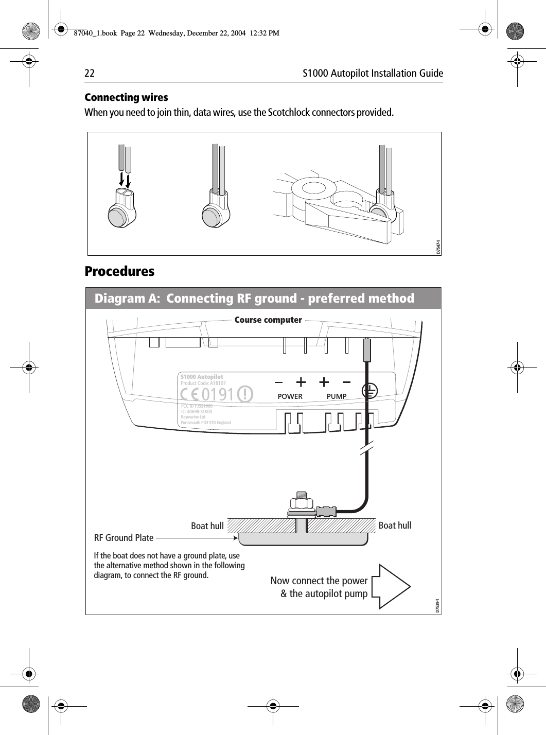
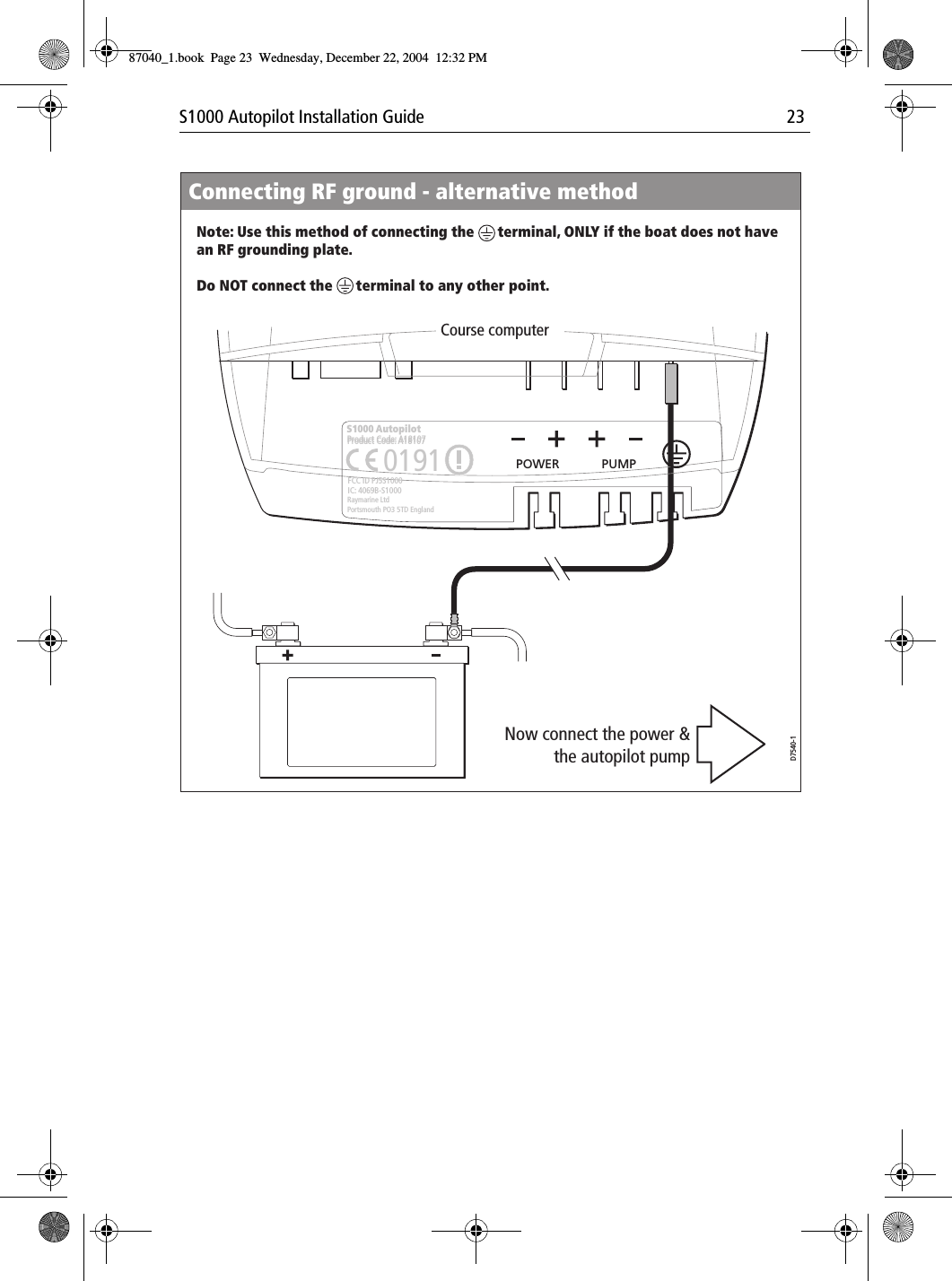
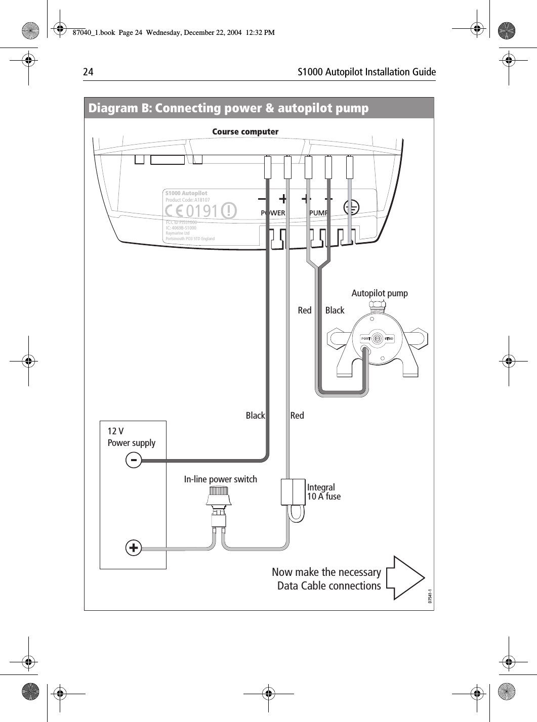
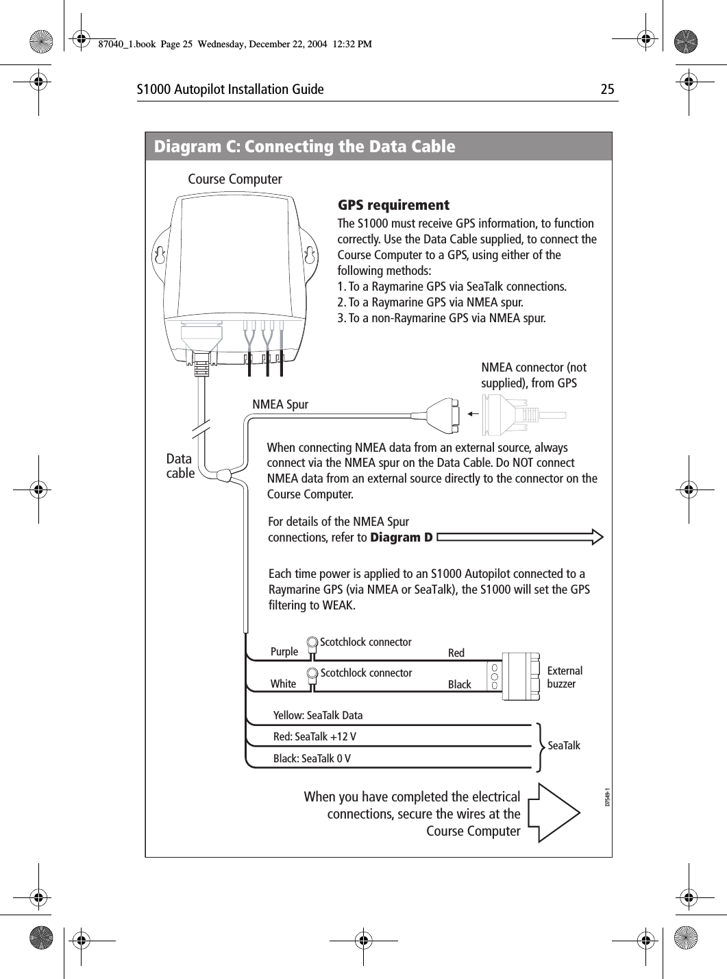
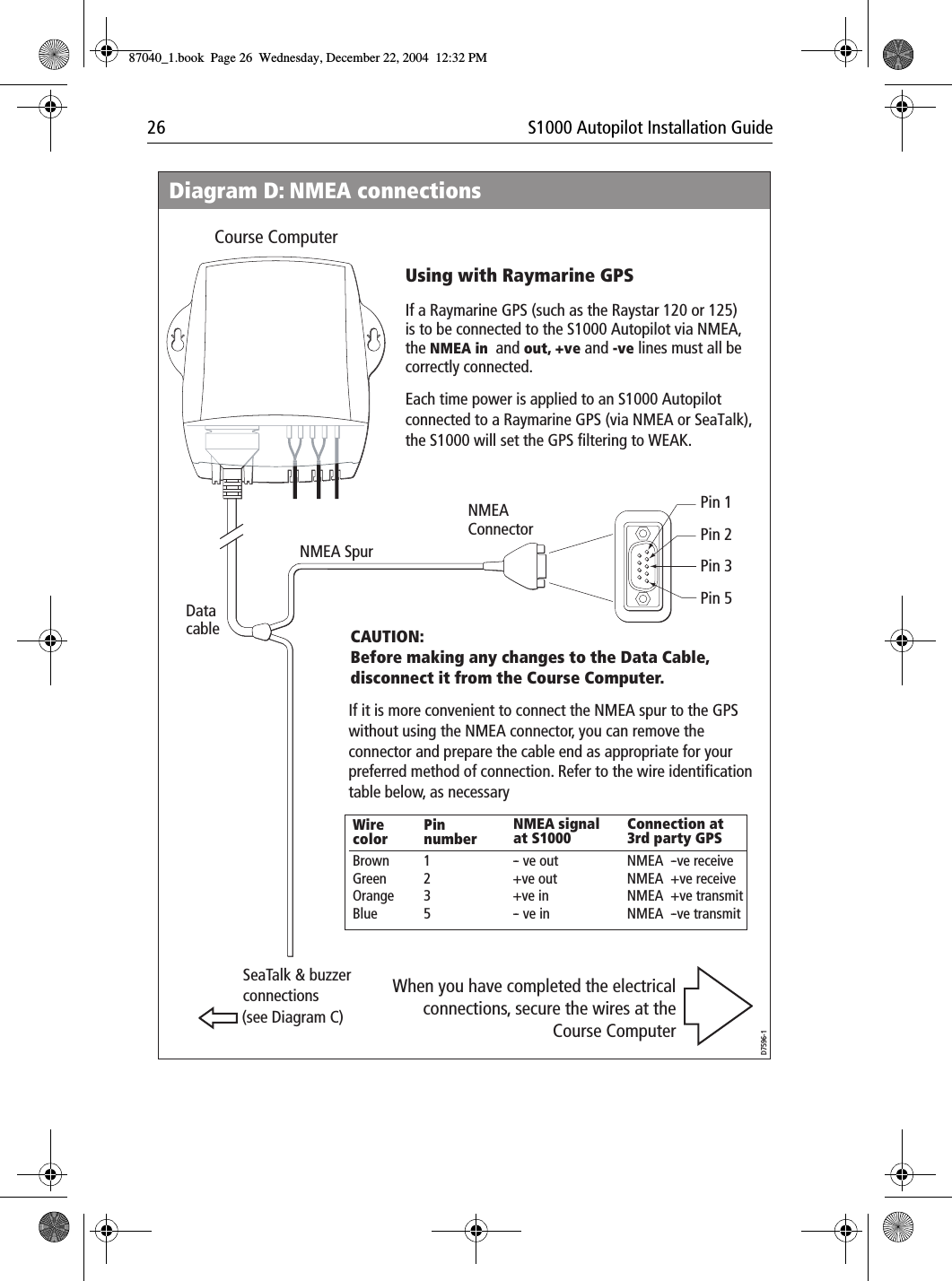
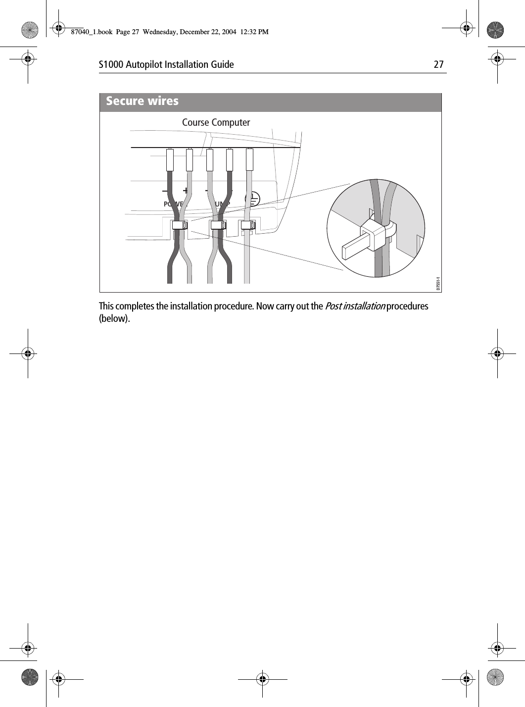
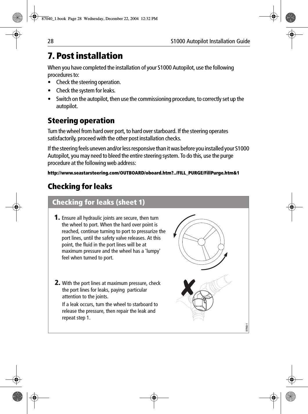
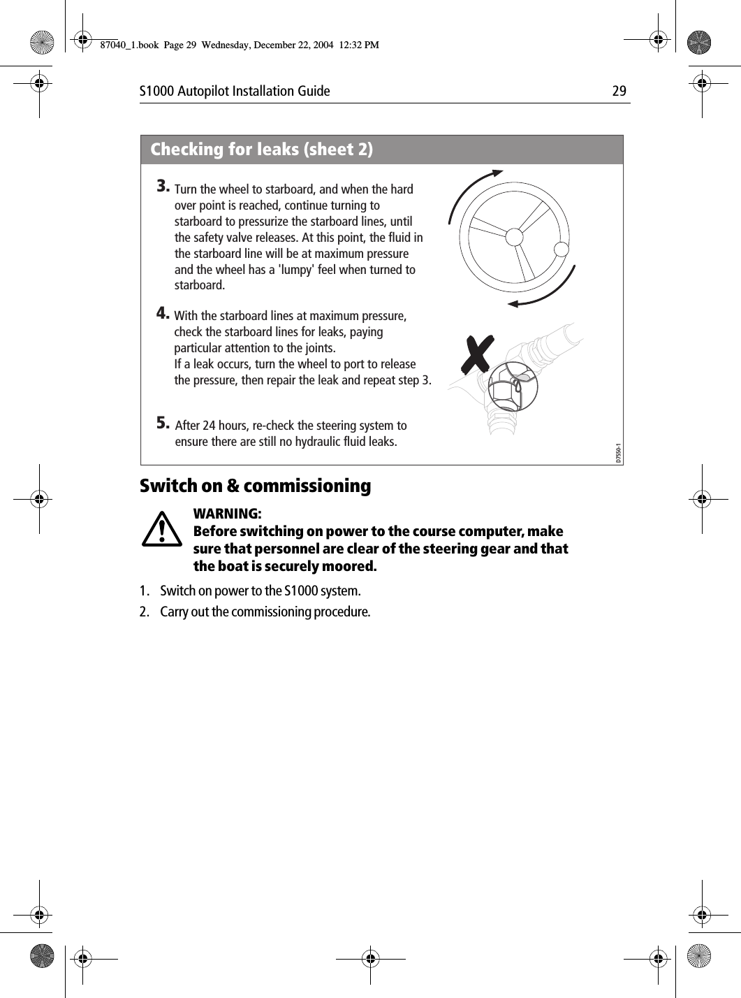
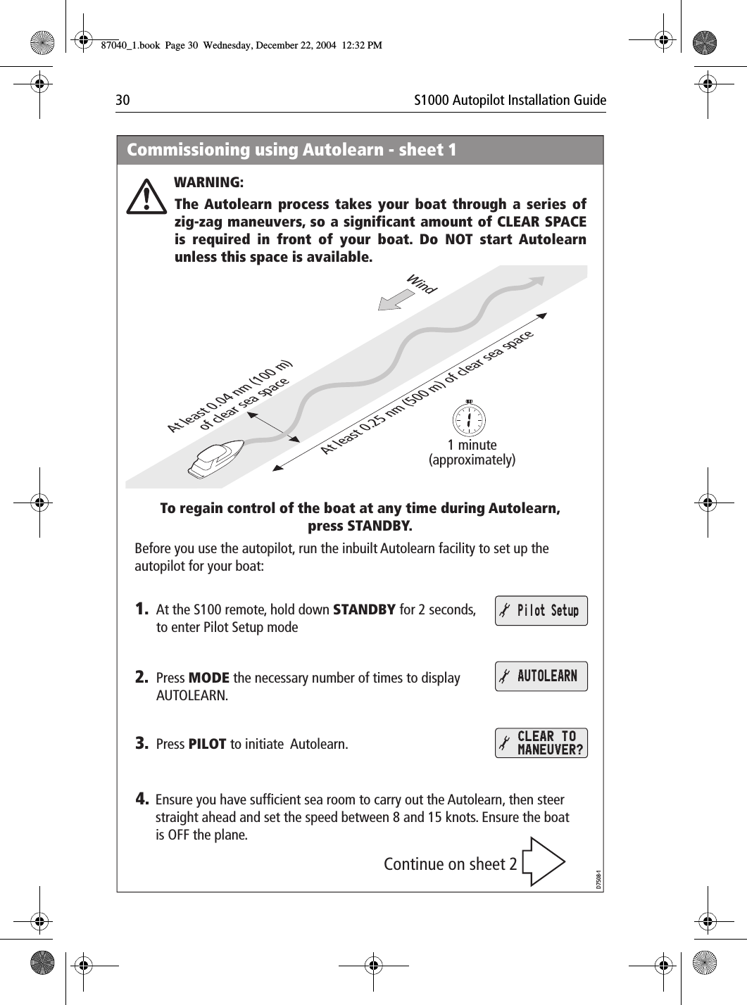
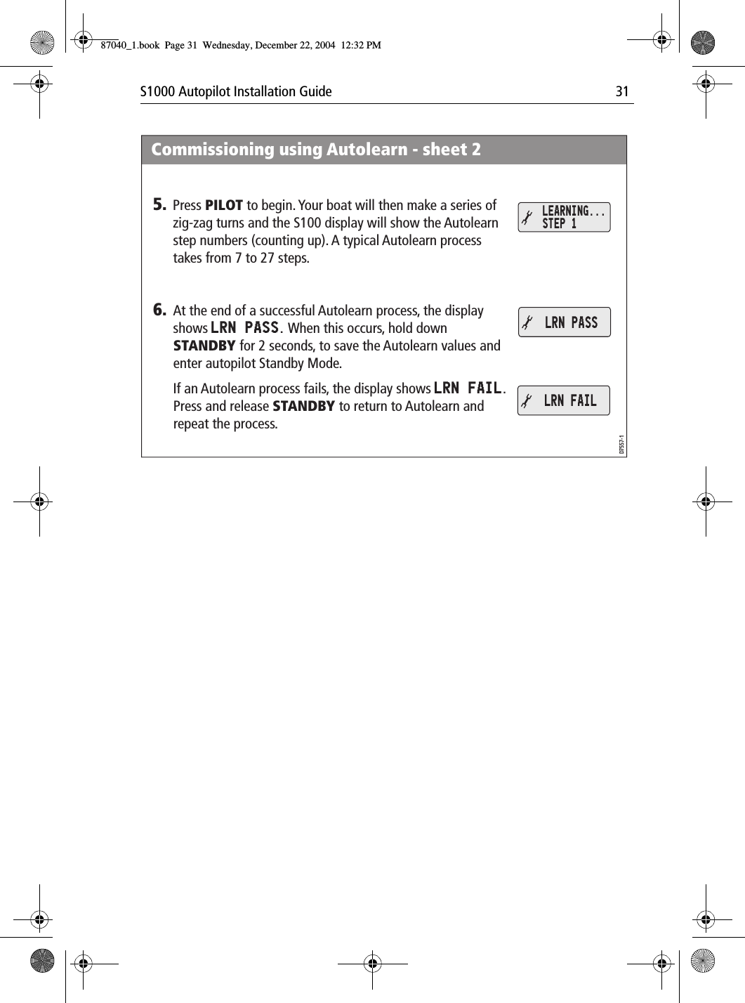
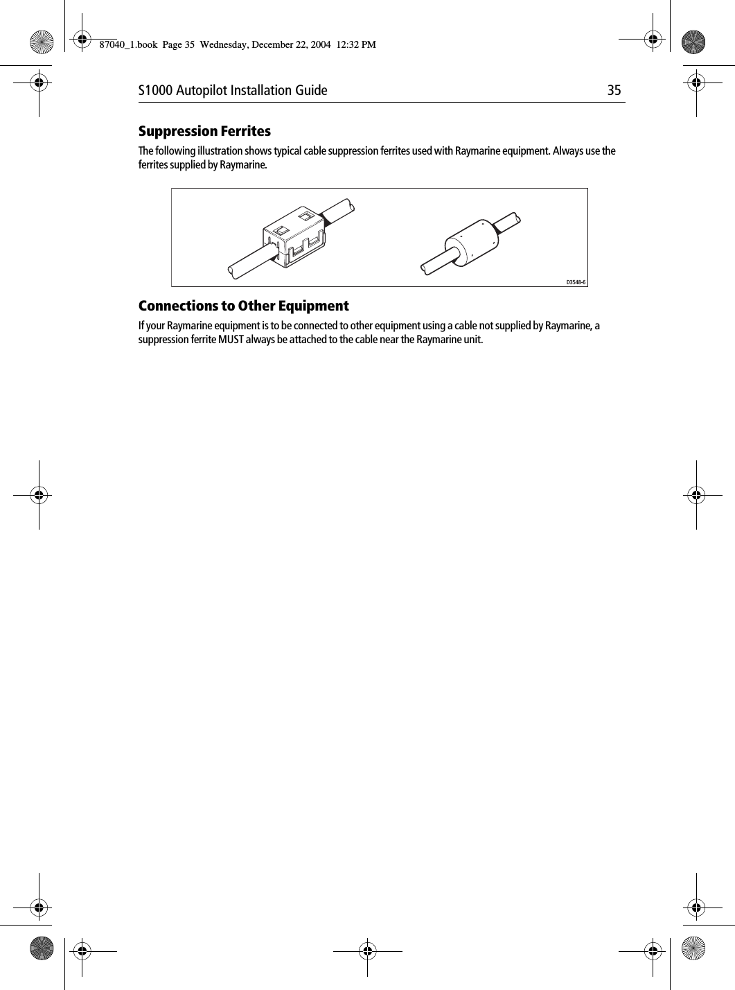
Installation Manual