Flow Data PROVUE Android based, touch screen operator interface User Manual
Flow Data, Inc. Android based, touch screen operator interface Users Manual
Users Manual

PROVue Manual V 1.2.5979
Installation, Operation and Maintenance

PROVue Manual V 1.2.5979 Page 1
Table of Contents
IMPORTANT NOTICE: .................................................................................................................................... 3
Safety Information ........................................................................................................................................ 4
ELECTRICAL SAFETY NOTE ......................................................................................................................... 5
BEFORE OPERATION .................................................................................................................................. 5
OPERATION AND ADJUSTMENTS .............................................................................................................. 6
LIFTING AND CARRYING ............................................................................................................................ 7
Introduction .................................................................................................................................................. 8
Installation / Replacement ............................................................................................................................ 8
Removal .................................................................................................................................................... 9
Installation ................................................................................................................................................ 9
Power Supply .............................................................................................................................................. 13
PROVue™ Operation ................................................................................................................................... 14
Operating Modes .................................................................................................................................... 14
User Login Control .................................................................................................................................. 15
PROVue™ Applets ................................................................................................................................... 15
Tanks ................................................................................................................................................... 16
Wells .................................................................................................................................................... 16
Summary Data ..................................................................................................................................... 17
Pad Items ............................................................................................................................................ 17
Login / Logout ..................................................................................................................................... 17
Alarms ................................................................................................................................................. 17
Reports ................................................................................................................................................ 18
Trending .............................................................................................................................................. 18
Accutech .............................................................................................................................................. 18
Safety Info ........................................................................................................................................... 18
Settings................................................................................................................................................ 19
Documents .......................................................................................................................................... 19
Help ..................................................................................................................................................... 19
Notes ................................................................................................................................................... 19

PROVue Manual V 1.2.5979
Page 2
Calculator ............................................................................................................................................ 20
Browser ............................................................................................................................................... 20
PROVue™ Web Interface ............................................................................................................................ 20
Connect to PROVue Web Interface ......................................................................................................... 20
Network Settings ..................................................................................................................................... 22
Screen Settings ........................................................................................................................................ 23
PadManager Application Setup .............................................................................................................. 24
Configuring communication with a controller .................................................................................... 24
Configuration overview ....................................................................................................................... 25
Adding a module to the configuration ................................................................................................ 25
Historical Tags and Trending ................................................................................................................... 27
PadManager Licensing ............................................................................................................................ 27
PROVue™ Reporting and Trending ............................................................................................................. 28
Scan Classes ............................................................................................................................................ 28
Adding Points to the Database ............................................................................................................... 28
Adding a Report Module ......................................................................................................................... 29
To Run a Report ...................................................................................................................................... 30
Viewing Trends ........................................................................................................................................ 31
Adding Trends to the Display .............................................................................................................. 31
Changing Trend Time – Date Range .................................................................................................... 32
PROVue™ User Accounts ............................................................................................................................ 33
PROVue™ WiFi Access Point ....................................................................................................................... 34
Maintenance ............................................................................................................................................... 35
Troubleshooting .......................................................................................................................................... 35
Specifications .............................................................................................................................................. 36
Contact ........................................................................................................................................................ 36
Class 1 Div 2 Statement ............................................................................................................................... 37
FCC/IC Statement ........................................................................................................................................ 41

PROVue Manual V 1.2.5979
Page 3
IMPORTANT NOTICE:
This documentation serves to provide the user with general use, installation and maintenance
information about the PROVue product. It also contains general descriptions of the technical
characteristics of this product. It does not provide analysis or information for determining suitability or
reliability of this product in user applications or solutions. It is the responsibility of the integrator or end
user to perform complete and appropriate risk analysis and testing to evaluate the suitability of this
product for any specific application or solution. Flow Data and its subsidiaries and affiliates shall not be
responsible for the use or misuse of the information contained herein.
All applicable national, state, territorial, regional and local safety regulations must be observed when
installing and using this product. To ensure safety and compliance with documented system parameters
and certification, only Flow Data should perform repairs to components.
For applications or solutions with technical safety requirements, all applicable safety guidelines and
manufacturer instructions should be followed. Failure to do so may result in injury or equipment
damage.
No part of this document may be reproduced in any form without prior written consent of Flow Data.
If you have any suggestions for improvement to this documentation, please contact Flow Data.
PROVue Manual V 1.2.5979
Page 4
Safety Information
Please read and understand these instructions and examine the equipment to become familiar with it
before attempting to install, operate or maintain it. The following table of messages and icons may
appear throughout this manual They specify potential hazards, point out special conditions, or illustrate
important points.
This symbol in a Danger or Warning label indicates the possibility of an
electrical hazard, which will result in injury or death if instructions and
safety precautions are not followed.
This symbol indicates a safety alert. It alerts you to safety messages
that must be obeyed to avoid personal injury or death.
DANGER
DANGER indicates an imminently hazardous situation which, if not avoided, will result in serious injury
or death.
WARNING
WARNING indicates a potentially hazardous situation which, if not avoided, can result in serious injury
or death.
CAUTION
CAUTION indicates a potentially hazardous situation which, if not avoided, can result in minor to
moderate injury.
PROVue Manual V 1.2.5979
Page 5
CAUTION
CAUTION without the safety symbol indicates a potentially hazardous situation which, if not avoided,
can result in equipment damage.
ELECTRICAL SAFETY NOTE
Electrical equipment should be installed, operated and maintained only by qualified personnel. Flow
Data assumes no responsibility for any consequences arising out the use or misuse of this material.
A qualified person is one who has skills and knowledge related to the construction, installation,
operation and maintenance of electrical equipment, and has received safety training to recognize and
avoid the hazards involved.
BEFORE OPERATION
CAUTION
EQUIPMENT OPERATION HAZARD
Verify that installation and setup procedures have been completed.
Before operational tests are performed, remove all tools, meters and debris from the equipment.
Ensure that any other equipment that is part of the installation is also ready for operation by following
manufacturer instructions and guidelines.
Failure to follow these instructions can result in personal injury or equipment damage.
Follow all start up procedures and tests recommended in these instructions.
Verify that the completed installation is free from short circuits and grounds, except those grounds that
are installed as directed by this document and those installed according to governing regulations, such
as the National Electrical Code (in the U.S.A. for example).

PROVue Manual V 1.2.5979
Page 6
OPERATION AND ADJUSTMENTS
The following precautions are from the NEMA Standards Publication ICS 7.1-1995 (English version
prevails):
Regardless of the care exercised in the design and manufacture of equipment or in the selection and
ratings of components, there are hazards that can be encountered if such equipment is improperly
operated.
It is sometimes possible to misadjust the equipment and thus produce unsatisfactory or unsafe
operation. Always use the manufacturer’s instructions as a guide for functional adjustments. Personnel
who have access to these adjustments should be familiar with the equipment manufacturer’s instructions
and the machinery used with the electrical equipment.
Only those operational adjustments actually required by the operator should be accessible to the
operator. Access to other controls should be restricted to prevent unauthorized changes in operating
characteristics.

PROVue Manual V 1.2.5979
Page 7
LIFTING AND CARRYING
The PROVue unit by itself weighs less than 5 pounds, and is easily lifted and carried in one hand.
If the PROVue is installed inside a PADPro panel, the entire panel including the PROVue weighs 36
pounds (16.3 Kg). The PADPro cabinet itself measures 16 in x 10 in x 26 in (40cm x 25.4cm x 66cm), so is
somewhat bulky. If the person attempting to lift and carry it feels uncomfortable with doing so, they
should arrange to lift it with someone else.
Make sure your pathway is clear before lifting
Keep your back straight – tuck in your chin as this helps
Bend at the knees – use your legs to lift, not your back
Place one foot beside and the other behind the PADPro, shoulder width apart
You can use the mounting flanges as hand holds if necessary
If lifting with another person, coordinate the lift and walk out of step
To lower the PADPro, bend your knees – do not stoop or bend at the waist!
Watch your fingers for pinches as you set it down.
If you have any questions regarding safety about lifting and carrying the PADPRo, consult your local
Safety Coordinator or Supervisor for guidance.

PROVue Manual V 1.2.5979
Page 8
Introduction
The PROVue Local Operator Interface (LOI) is a state of the art touch screen graphical interface powered
by the Android™ operating system running the PROVue™ Application. It is used to configure, manage,
trend and report solutions created with the PadManager™ software running on a SCADAPack 300 series
or SCADAPack 4203 series controller.
Key features of the PROVue are its familiar “App” centered interface and its embedded SQL Lite
database. Both of these allow unprecedented ease of operator control and data point trending and
reporting.
The modularity of the underlying PadManager software allows field technicians to make necessary
changes to individual configuration requirements, per installation with no formal programming training.
Because the PROVue is used with the PadManager software, it is designed to respond to whatever
configuration it finds, updating its own interface components as necessary to allow operator interaction.
This allows quick field customization with no additional reprogramming of the interface component.
Other features include a local Wi-Fi Access Point, and a built in web interface to control functions and
PadManager Application Setup. The web interface allows the user to configure and add custom reports
to the PROVue database itself, allowing much finer grained reporting than standard PLC data logging.
Installation / Replacement
Physical installation of the PROVue is easy and straightforward. It is supplied as a field replaceable unit
to the PADPro.
WARNING

PROVue Manual V 1.2.5979
Page 9
WARNING: EXPLOSION HAZARD. DO NOT DISCONNECT WHILE THE CIRCUIT IS LIVE OR
UNLESS THE AREA IS KNOWN TO BE FREE OF IGNITIBLE CONCENTRATIONS.
AVERTISSEMENT : RISQUE D'EXPLOSION. NE DÉCONNECTEZ PAS ALORS QUE LE CIRCUIT EST
SOUS TENSION OU À MOINS QUE LA ZONE EST CONNUE POUR ÊTRE LIBRE DES
CONCENTRATIONS INFLAMMABLE.
Removal
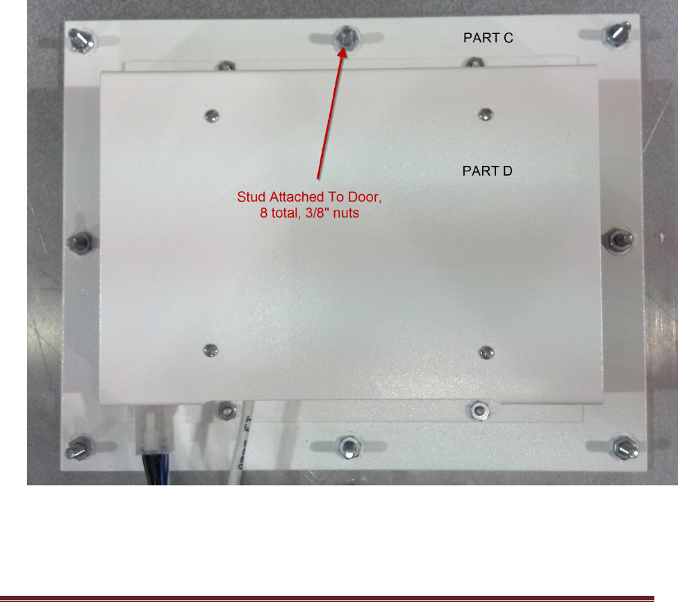
Refer to Figures 1, 2 and 3. Remove the connectors. Remove the eight 3/8” nuts. Pull gently on the
assembly from the back, while using your fingers to help the gasket “unseal” from the front edge of the
mounting hole. Once free from the front edge, the whole assembly will pull away easily.
Installation
The following instructions assume field replacement of the PROVue, with the defective unit already
removed as described above.
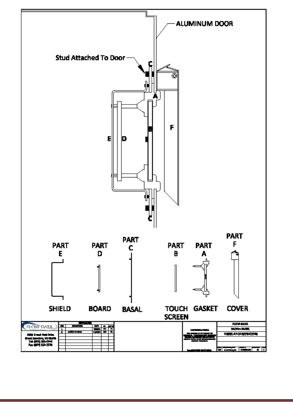
See figure 1. Part C is the back plate. The entire unit is secured to the mounting position in the door by
this back plate, with eight 3/8” nuts. The studs are part of the door assembly.
PROVue Manual V 1.2.5979
Page 10
Figure 1 - Cut-away installation detail
PROVue Manual V 1.2.5979
Page 11
Physical Installation
1. Refer to Figures 1 and 2.
2. Position the unit so that Part A (gasket) is centered in the door cutout.
3. Begin to tighten the nuts in an alternating pattern, so that moderate pressure is applied evenly
to the back plate. Do not over-tighten.
4. Continue to tighten the nuts, ensuring that pressure is applied evenly – as you continue, the
gasket will begin to press-fit into the mounting hole. It should “snap” into place.
5. If the gasket does not fully seat, use fingers to gently help the gasket through.
6. Once the gasket has fully snapped into place, tighten the nuts another half turn.
7. The cover should already be in place, but if not, it is secured with double sided tape. Simply
remove the backing to the tape, center the cover over the display and push it into place.
Figure 2 - Mounting, back view
PROVue Manual V 1.2.5979
Page 12
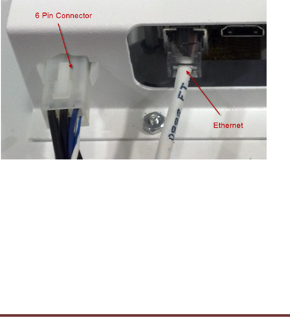
Electrical Connections
1. Refer to Figure 3.
2. Reconnect the 6 pin Molex connector. This supplies power, ground and front panel button
connections.
3. Reconnect the Ethernet cable.
Figure 3 – Electrical Connections

PROVue Manual V 1.2.5979
Page 13
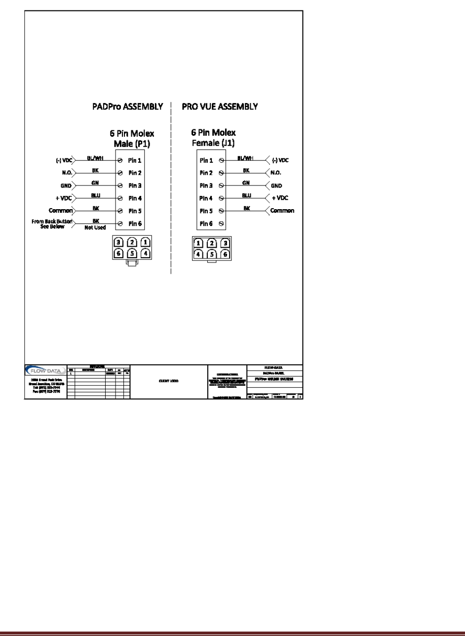
Power Supply
The PROVue is designed for battery operation. It operates on 7 – 14 VDC, and draws up to 430 mA on
initial startup. Under normal operation, when the backlight has turned off, the unit draws about 235
mA. With the backlight on, it draws about 415 mA. The wiring harness provides connections to the
power supply. P1 comes from the PADPro enclosure and plugs into J1, which is part of the PROVue
assembly. J1-1 connects to the negative supply, J1-4 connects to the positive supply. J1-3 connects to
earth ground. J1-2 and J1-5 connect to the front panel display button (NO contacts, non-polarized). J1-
6 is unused. Refer to Figure 4.
PROVue Manual V 1.2.5979
Page 14
Figure 4 - Connector pin-out
PROVue™ Operation
Operating Modes
The PROVue is always powered and operating. It is always monitoring user configured data points,
providing wireless network Access Point access, and providing SQL database queries of data that it is
trending. When the user is currently using the PROVue as an LOI, it will power its backlight so that the
user can interact with the touch screen. After a period of user inactivity (usually 20 minutes), it will turn
the backlight off to conserve power. When a user wishes to use the LOI again, he or she will press the
front panel Display button. This will signal the PROVue to power the backlight once again.

PROVue Manual V 1.2.5979
Page 15
User Login Control
The PROVue allows the operator to configure individual user access to the PADPro. As supplied, the
PROVue has one user defined: admin. The default password is: default
Once a new user with admin privileges is defined, the default admin user is replaced and is no longer
available. It is recommended that the user change the default user and password to prevent
unauthorized changes to the PADPro™ and PROVue™.
You can create as many users as necessary – the only limit to how many users you can define is the
amount of memory available for the database.
New users are defined through the Application Setup web interface provided by the PROVue. See the
section PROVue User Accounts for more information.
The Summary Data, available from the main screen, is available to any user without any login required.
This provides regulatory agencies (such as BLM) access to the data that they need for monitoring and
regulatory compliance.
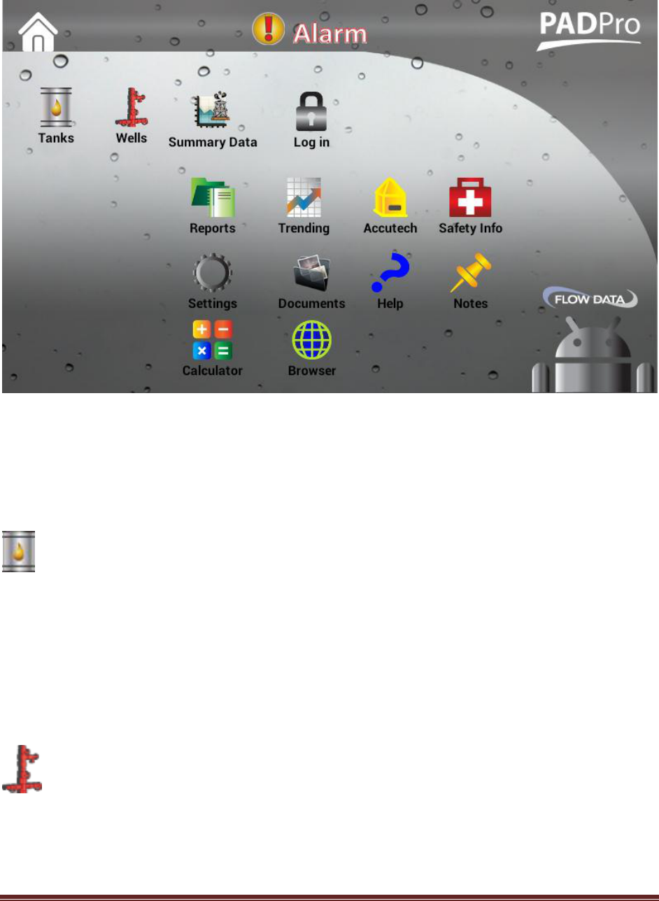
PROVue™ Applets
From the main screen, there are several applets available to the user for monitoring wells, tanks, alarms
and other system status and settings. Refer to Figure 5.
PROVue Manual V 1.2.5979
Page 16
Figure 5 - PROVue Applets
Tanks
This applet provides the user with operational information about the tanks on a site. It provides access
to individual tank data and to aggregate tank group data. Alarms associated with tank groups and
individual tanks are accessible from here. You can also see all alarms in the system with the Alarm
applet – see that section for more information.
Wells
This applet provides the user with operational information about the wells on a site. It provides
individual well control and operational status. For example, operators can open or close a well, monitor
the flow rate, change operational parameters and select options that modify the behavior of the well

PROVue Manual V 1.2.5979
Page 17
control, such as shut in on line pressure. The options and controls available depend on the
configuration that is running on the PADPro solution.
Summary Data
This provides regulatory agency access to the data they need for monitoring compliance. No user login
is required for this applet, and no control functionality is available.
Pad Items
This provides quick access to custom pad-wide data points that do not fit directly into Tank or Run
categories, such as analog or digital inputs from auxiliary equipment. These points are specified in the
Application Setup interface that the PROVue provides.
Login / Logout
Before accessing any applet, except the Summary Data and the Alarms, the user must log in to the
PROVue. By default, the PROVue has one administrator account, admin, with the password default.
Administrator accounts have complete access to the configuration and operation of the PROVue LOI.
When a new administrator account is created, the default admin account becomes inactive. There is no
real limit to the number of users that can be created, other than total available memory. Access can be
configured by level.
Alarms
This applet is accessible from any other applet or from the main screen. It provides a display of all active
alarms in the system, and a history of past alarms. It also provides the means to clear alarms, if the
alarm condition(s) no longer apply.

PROVue Manual V 1.2.5979
Page 18
Reports
This applet gives the user local access to reports that have been configured and added through the
PROVue web interface. See the PROVue Reporting section for information on defining and adding
reports. Reports displayed through the web interface can be downloaded as an Excel spreadsheet to
your local device.
Trending
Data point trending on the local interface is a powerful tool for the operator. Coupled with the ability to
add any data point or tag in the system to the SQL Lite database on the PROVue, an unprecedented level
of information is now available to operators, well and reservoir analysts. Data can be stored for well
over a year – limited only by the amount of memory on the installed SD card. A year’s worth of data is a
reasonable expectation, even higher resolution data such as three minute trends. You must set up
trended “Historical” tags from the Application Setup interface. See the PROVue Trending section for
more information.
Accutech
This applet provides instant graphical feedback to the operator on the status of each wireless device
installed. Using color coded icons, devices in full operation are green, non-fatal errors are orange, and
devices with no communications are red. The battery status of each device is also reported on these
screens.
Safety Info
Custom safety information can be placed on the PROVue, and this applet provides access to it. The
PROVue is capable of video playback, and safety video productions can be placed here for personnel to
access. Any video on any subject can be placed here, from safety to training to procedures.

PROVue Manual V 1.2.5979
Page 19
Settings
This applet gives administrator accounts control over the PROVue communications and other settings. It
is also the applet to use for turning the WiFi Access Point on and off.
Documents
This applet provides access to any factory or custom documentation placed on the PROVue. For
example, from the factory, the PADPro drawings and wiring details are placed here in PDF format for
viewing by technicians and installers. Any other documentation that the user needs to maintain and
have accessible on site can be placed on the PROVue .
Help
This applet launches built in documentation about the PADPro and the PadManager software that runs
on it. In addition, information such as the basics of gas and oil well operation, pump off control, basic
electronics, troubleshooting, PadManager customization and more are included.
Notes
Operators can use this applet to write down notes to themselves or for other operators. Changes,
maintenance notes or anything else useful can be maintained locally. Nothing to blow away in the wind
like hand written notes left inside enclosures or mailboxes.

PROVue Manual V 1.2.5979
Page 20
Calculator
This provides a standard calculator for simple math.
Browser
This applet provides a simple web browser, so that operators can use an Ethernet backbone (radio, cell
modem) to access company intra-nets or the internet. This allows operators or technicians to access
data in a familiar web interface.
PROVue™ Web Interface
The PROVue is used to monitor and control pad, well and tank operation solutions running on a
SCADAPack controller. These solutions are created and managed through a configuration tool provided
by PROVue. The PROVue provides a built in web server that hosts an Application Setup web page.
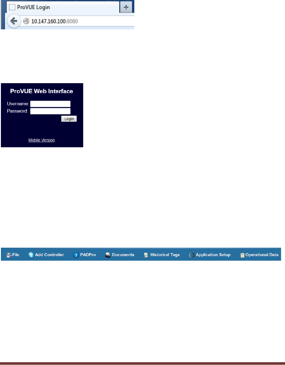
Connect to PROVue Web Interface
Using any web browser on any device (laptop, phone, tablet, etc.) you can connect to the IP address of
the PROVue, at port 8080. The PROVue has two Ethernet addresses. The first, shown in Figure 6 below,
PROVue Manual V 1.2.5979
Page 21
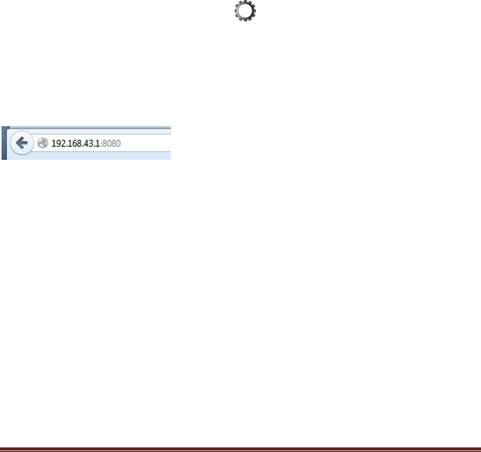
is 10.147.160.100. The second is the address to use when connecting through the WiFi Access Point (the
Access Point must be on – see the PROVue WiFi Access Point section for how to do this).
Figure 6 - Browser connection – Ethernet port address is shown – the WiFi address is 192.168.43.1:8080
Once connected (either through the physical Ethernet or the WiFi), you will be presented with a login
screen. By default, the login user name is “admin”, and the password is “default ” (without the quotes of
course).
Figure 7 - PROVue Web Login
Once logged in to the web interface, you are presented with the Application Setup page. A menu of
options and operations appears in a banner across the top of the page. The File option allows you to
export and import configurations, perform SQL queries on the PROVue database, and manage users. The
Add Controller option allows you to add another controller, such as a 4203DS, to a configuration. The
PADPro option displays online help. The Documents option shows the available documents loaded in
the PROVue, such as drawings, notes, videos and pictures. The Historical Tags option allows you to view
all of the tags defined for trending in the PROVue. The Application Setup option provides access to
settings such as the Stale Data timeout.
Figure 8 - Menu Header
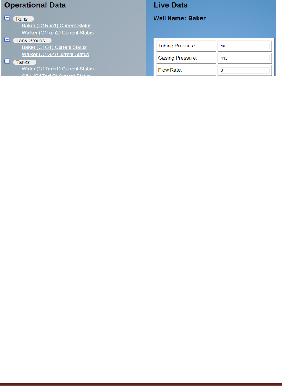
The main body of the page is split into two panels. The left hand panel contains links to the current
system operational data and to the system configuration. The right hand panel contains any data or
associated configuration options for items selected in the left hand panel.
At the top of the left hand panel, there is a tree of selections that allow you to look at a snapshot of
operational data. This snapshot is taken when the page loads, and refreshes itself every minute. You
can force a refresh by pressing the F5 key or the Reload icon on your browser.
PROVue Manual V 1.2.5979
Page 22
Figure 9 - Operational data snapshot
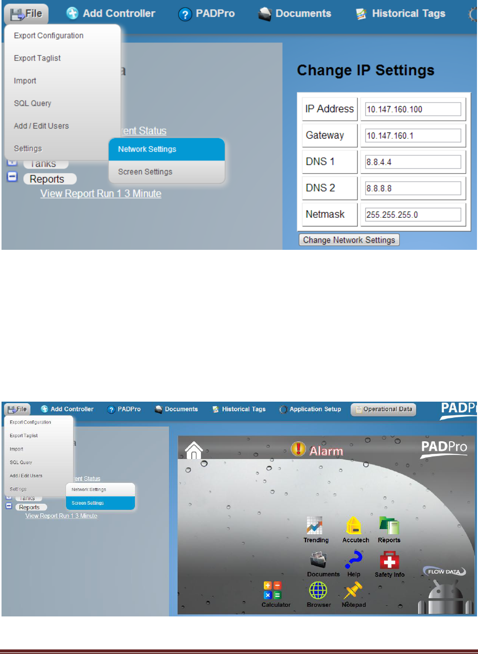
Network Settings
From the factory, the PROVue display is set to use an internal IP address of 10.147.160.100. This can be
changed from the top menu selection of File – Settings – Network Settings.
Refer to the figure below. The IP address applies to the internal hard-wired Ethernet network port. The
Gateway is the IP address of the gateway on that network. In many cases, this will be the Ethernet radio
address or the address of the cell modem. The DNS servers are whatever your networking requirements
dictate. The netmask is usually 255.255.255.0 on a class C network.
For any network settings, consult with your network administrator. The defaults are:
IP Address: 10.147.160.100
Gateway: 10.147.160.1
DNS1: 8.8.4.4
DNS2: 8.8.8.8
Netmask: 255.255.255.0
PROVue Manual V 1.2.5979
Page 23
Figure 10 - Network Settings dialog for the PROVue
Screen Settings
The PROVue has a selection of icons on its main screen that launch small apps. For example, there is a
Well icon that launches the well monitoring application. Some of these icons may or may not be useful
to the end user. From the web interface, it is possible to disable the display of some of these icons.
Refer to the figure below.
Figure 11 - Screen Settings customization
PROVue Manual V 1.2.5979
Page 24
In this figure each of these icons is displayed in full color. This indicates that they will be displayed on
the screen of the PROVue. By clicking on one or more of these, they will become “greyed” out. This
indicates that they will not be displayed on the screen. In this way it is possible to restrict users from
launching the Browser, for example. The basic Tank, Well, Summary, Log-in/out, and Pad Items icons
cannot be disabled.
PadManager Application Setup
The left hand panel of the Application Setup page contains the various configured modules that define
the functionality of the underlying SCADAPack. It also contains the configuration necessary for the
PROVue to interface with the SCADAPack. The right hand panel will display the configuration and tags in
the system. Users can add any tag in the system for trending, and can build reports from this interface
that use these historical data tags. For more about that feature, see the section PROVue Reporting.
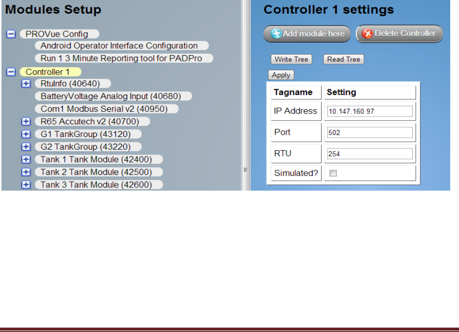
Configuring communication with a controller
To configure the PROVue to communicate with a controller, click the “Controller” module of interest in
the left hand area. The settings for this controller will appear in the right hand area. In the figure below,
settings for Controller 1 are shown. After entering the information, click the “Apply” button. It is not
necessary to write the configuration tree out to the controller for this to take effect.
Figure 12 - Configuring communication with a controller
PROVue Manual V 1.2.5979
Page 25
Configuration overview
Modules can be added to any part of the configuration as needed, and as appropriate. The rules for
module placement and how each type is configured are covered in the PADPro Solution User Manual.
Configurations are arranged in a hierarchy much like a family tree. There is a root to this tree, and from
this root other modules are attached like branches (children), extending outward to the “leaves” at the
end.
Controller modules are root modules that their particular configuration is attached to. Each controller
has its own configuration tree. In the figure above, Controller 1 is a root module. You can see the
RTUInfo, BatteryVoltage Analog Input, Com1 Modbus Serial and R65Accutech modules that are
branches to it. These are children of the Controller 1 module. The RTUInfo Module has a branch “child”
module called RTU Coils. The R65 Accutech module has a branch “child” module called Accutech Status.
Modules that have no children are sometimes referred to as “leaves” on the tree.
The module names are displayed along with the Modbus address that their settings “live” at in the
controller. You can find the address of any point (tag) in the system by clicking on the module and
observing the data displayed in the right hand panel. Every point has its address shown.
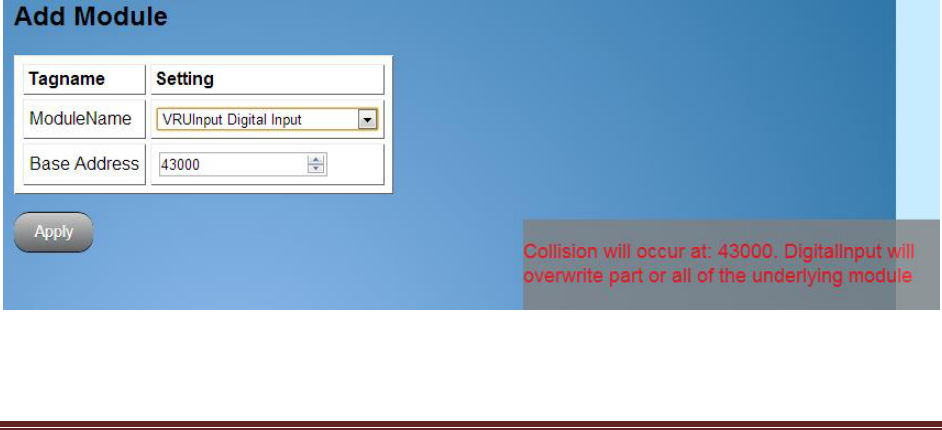
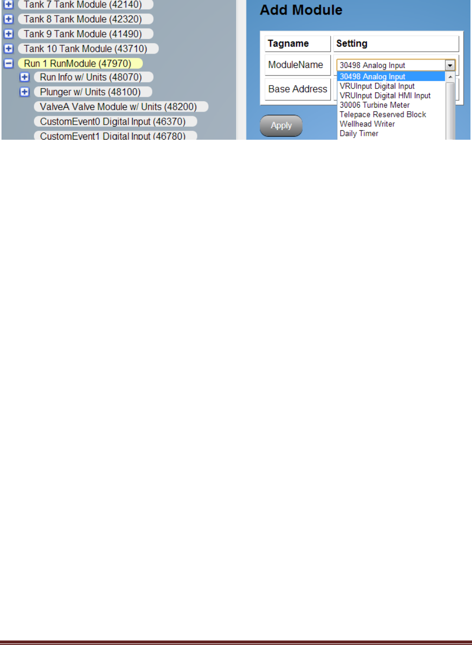
Adding a module to the configuration
In this example, we will be adding an Analog Input module to Run 1 so that we can use a wired casing
pressure sensor.
Select the Run 1 RunModule and then click the Add Module Here button. This will bring up a selection
drop down box with all the available modules in the system. Select the Analog Input Module. The Base
Address of the module is selected automatically. You can change this address if necessary, and there is
a graphical memory map utility built in to the interface. If a selected address will result in a collision
between the module you are adding and another module, a warning will appear on the screen. See
Figure 11 below.
Figure 13 - Address collision warning
PROVue Manual V 1.2.5979
Page 26
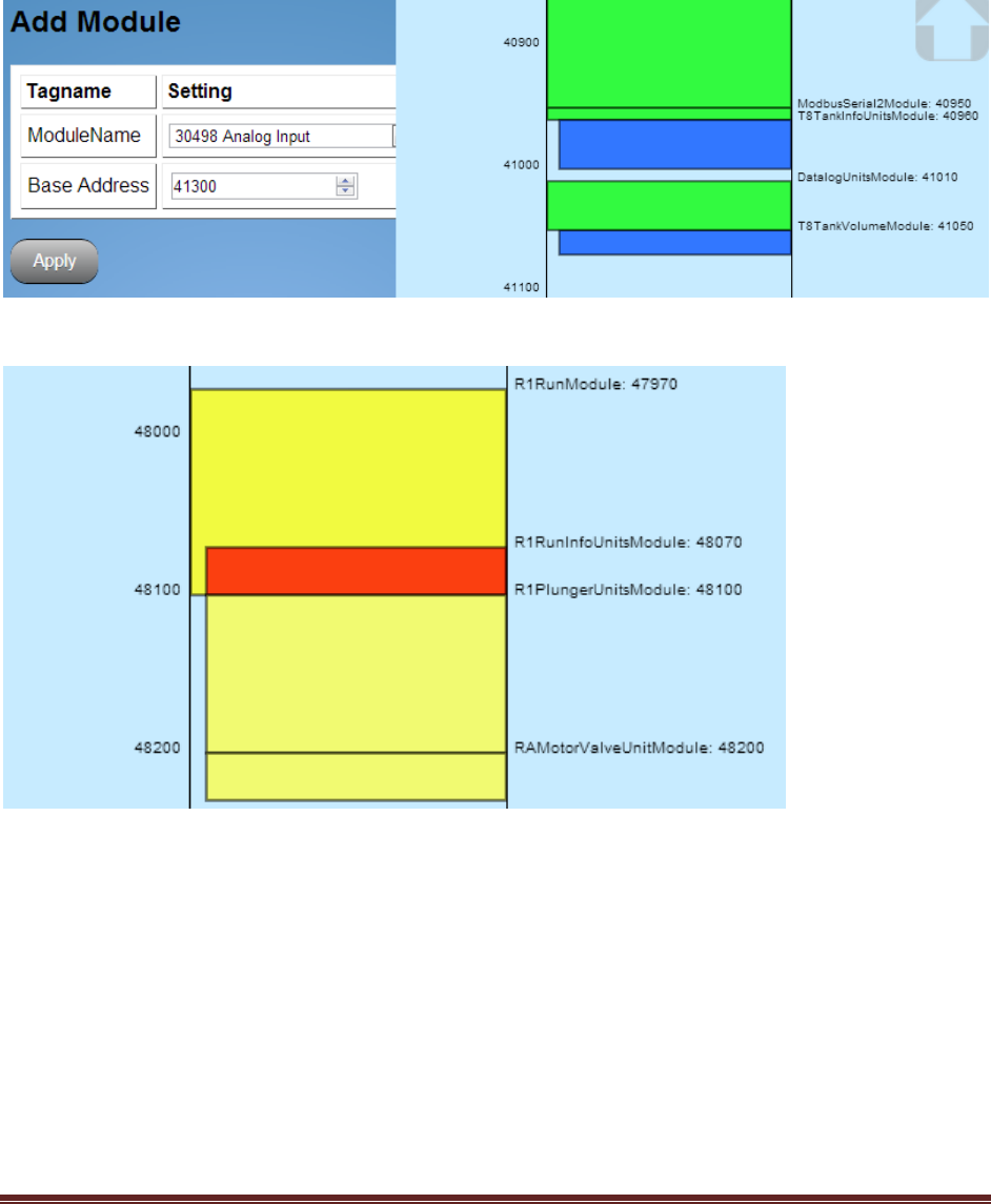
A graphical display of the current memory map is available. Click on the small arrow in the lower right of
the screen – a browsable display will slide into view, allowing you to lookfor address blocks that are both
occupied and available for use. Overlapping modules are highlighted in red. See figures 12 and 13
below.
Figure 14 - Memory map with allocated and free blocks
Figure 15 - Collision between modules
For more information about how addressing works and the considerations for selecting an address, see
the PADPro Solution User Manual.
PROVue Manual V 1.2.5979
Page 27
Figure 16 - Adding a module
Make sure you click the Apply button to insert the module into the configuration. If you do not, the
change you made to the configuration will not take effect, and you will notice that the added module
does not appear in the configuration tree display. Press the F5 button or reload the page to refresh the
configuration tree display after clicking the Apply button.
The Analog Input Module should be at the bottom of the Run 1 section of the configuration. Clicking on
it will bring its’ settings up in the right hand panel. Make any necessary changes to the module settings.
Be sure to click the Apply button! Changes made will not take effect otherwise.
Once you have added and configured a module, or made configuration changes to an existing module, it
is necessary to write the new configuration out to the controller. You do this by clicking on the
Controller module, then clicking the Write Tree button. It may take up to a minute to write long
configurations to the controller. Be patient! Once it has successfully written the configuration, you will
receive a Configuration Successfully Written message. Press F5 or reload the page in your browser to
refresh the configuration display.
Historical Tags and Trending
Any data point in the system can be trended. These are referred to as Historical tags. For more detailed
information, refer to the Reporting and Trending section of this manual.
By selecting a module of interest, every tag associated with thata module is displayed in the right half of
the web page. Each tag has two buttons associated with it. The first is “Add to History” and this is the
button to press to add that tag to trending. See figure 18. The second is “Add to Clipboard”, which
allows you to add arbitrary tags to a “clipboard” display that will be available on the front panel.
PadManager Licensing
The PadManager firmware needs to be licensed in order to run. The licensing takes place from the
Application Setup web page. Click on the controller that needs licensing. In the right-hand pane the
PROVue Manual V 1.2.5979
Page 28
connection information should be visible. On the right of this information is a button labeled “License”.
This will open a new right hand pane in which you enter the license codes supplied by Flow Data.
License codes are specific to a controller and will not work in any other controller. There are
registration codes displayed in this window that can be used by Flow Data to provide the licensing codes
needed.
PROVue™ Reporting and Trending
The PROVue interface has built-in report generating and trending capability. It runs an SQL Lite
database locally that allows it to track any point (tag) in the system. This is the trending history
database referred to in the following discussion. Reports draw their data from this trending database.
Scan Classes
There are currently three “Scan Classes” that define the kind of trending that a tag will receive: Daily,
Hourly and 3-Minute. Daily tags will be synchronized to the PROVue Config contract hour. Hourly and
3-Minute trends are synchronized to an internal timer that begins when the PROVue boots up. Tags that
are added between hourly and 3 minute ticks of this timer will not be recorded until those ticks occur.
For example, the Tubing Pressure tag gets added to the 3-Minute scan class. It happens that the
addition is made 1 minute after the last 3 minute tick. It will be 2 more minutes before the first Tubing
Pressure will be recorded. This applies to items added to the Hourly class. If the tag is added 15
minutes after the last hourly tick, it will be 45 more minutes before that tag is recorded.
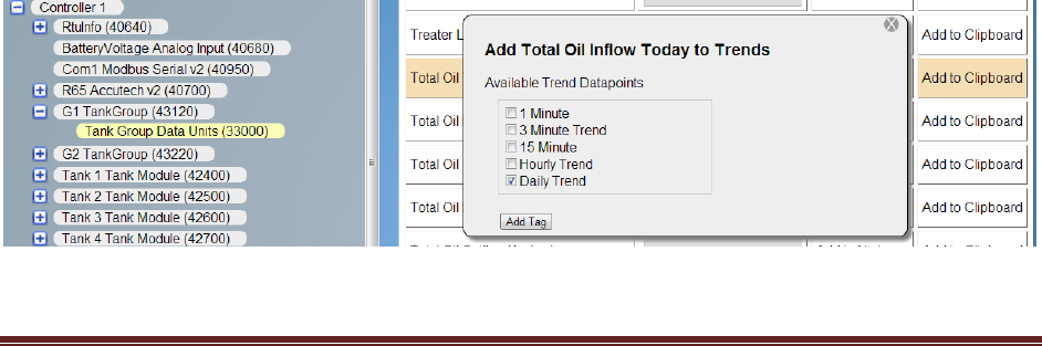
Adding Points to the Database
To track points, the user selects a module definition and finds the point that they are interested in.
Refer to the figure below.
Figure 17 - Adding points to the database for trending / reporting
PROVue Manual V 1.2.5979
Page 29
Here, we are interested in adding the tubing pressure for a tank group to the trending database. By
selecting the Tank Group Data Module, a list of available points is displayed. Finding the Well Tubing
point, we simply click the Add to History button. This brings up a dialog box that allows the selection of
which “scan class” to add the point to. We may select one or more scan class – the point can be trended
in all available classes at the same time.
Tags that have been added to the trending database will be highlighted and noted. See the figure
below.
Figure 18 - Added tags
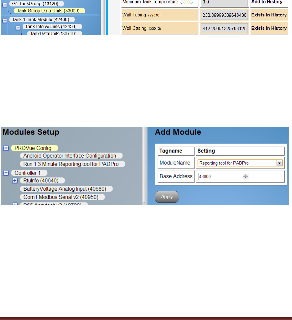
Adding a Report Module
In order to add a report that uses this data, we must “add a module” to the PROVue Config section in
Application Setup. The PROVue is configured through its own “module” system. One of these modules
is the Reporting Tool for PADPro. Clicking the Add Module Here button will bring up an Add Module
drop down list.
Figure 19 - Add Reporting Tool
The Add Module drop down list allows selecting the Reporting Tool. The Base Address is unused, so
ignore it. Future software releases will not have the Base Address setting. Once the Reporting Tool is
selected, click the Apply button.
Now refresh the Application Setup screen by pressing F5 or reloading the page in your browser. This will
reload the configuration tree in the left hand panel, allowing you to see the Reporting Tool module in
the PROVue Config section.
PROVue Manual V 1.2.5979
Page 30
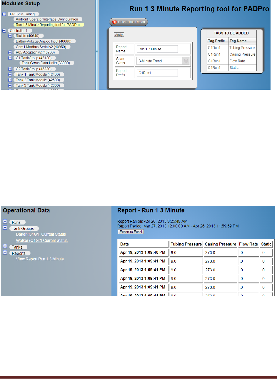
Figure 20 - Configuring the Report
Here you supply a name for the report. You can add any point (tag) to the report, no matter what its’
“Scan Class” is. The points displayed on the right hand panel reflect the currently trended points for the
selected Scan Class. By clicking the Scan Class box, you can also select Hourly and Daily trended points.
The Report Prefix, in version 1.0 of the PROVue, must be filled in by hand. It is based on the Tag Prefix in
the list of points. In this case, we have filled in C1Run1. The Prefix names denote the controller and the
item. In this example, C1 means Controller 1. Run1 is of course the first well, or run. You can include all
the trended tags for Controller 1 by only using C1 as the prefix. Similarly, C1Run1 selects all the trended
tags for Controller 1 Run 1. Once the report is configured, click the Apply button, then press F5 or reload
the page in your browser. You will see the newly named report in the Operational Data section of the
Application Setup left hand panel.
Figure 21 - Report Results
To Run a Report
To run a report, simply click on the report to highlight it. For longer reports, it may take a short time for
them to run. Once they have finished, the data will be displayed in the right hand panel of the page.
PROVue Manual V 1.2.5979
Page 31
Reports can also be run from the PROVue display itself, using the Report applet.
You can export the report from the web interface to an Excel spreadsheet by clicking the link at the top
of the report page. An almost unlimited number of reports can be added to the PROVue.
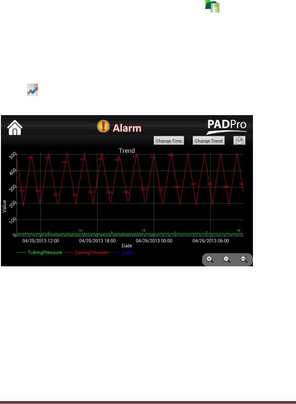
Viewing Trends
You can view the tag data as a graphic trend on the PROVue. From the main PROVue screen there is a
Trending applet. Running this applet will load the currently defined tags; if any tags have previously
been selected for display, it will display them.
Figure 22 - Trending Applet
Refer to Figure 17 above. The trending for two previously displayed tags, Tubing and Casing pressure
are displayed. If no trends have been previously viewed, this screen would be blank, except for the
buttons at the top right.
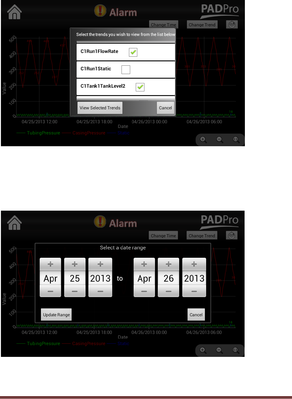
Adding Trends to the Display
Press the “Change Trend” button. This will bring up a dialog window that displays all of the 3-minute
trend tags that have been added through the web interface. You can select one or more of these to
display. The screen will automatically adjust the graph scaling to display the data. If there are large
variations in values, as above, it may be difficult to observe finer detail. You can use the familiar “pinch
zoom” or the + icon to zoom in on the graph. Using your finger, you can “drag” the graph around as
desired. Refer to Figure 18 below.
PROVue Manual V 1.2.5979
Page 32
Figure 23 - Trend Selection Dialog
Changing Trend Time – Date Range
You can change the range of data displayed by simply dragging the graph left or right. You can make
larger range changes by pressing the Change Time button. This will bring up a dialog that allows you to
select a beginning and ending date range for the graph. See Figure 19 below.
Figure 24 - Changing Date Range of trends
PROVue Manual V 1.2.5979
Page 33
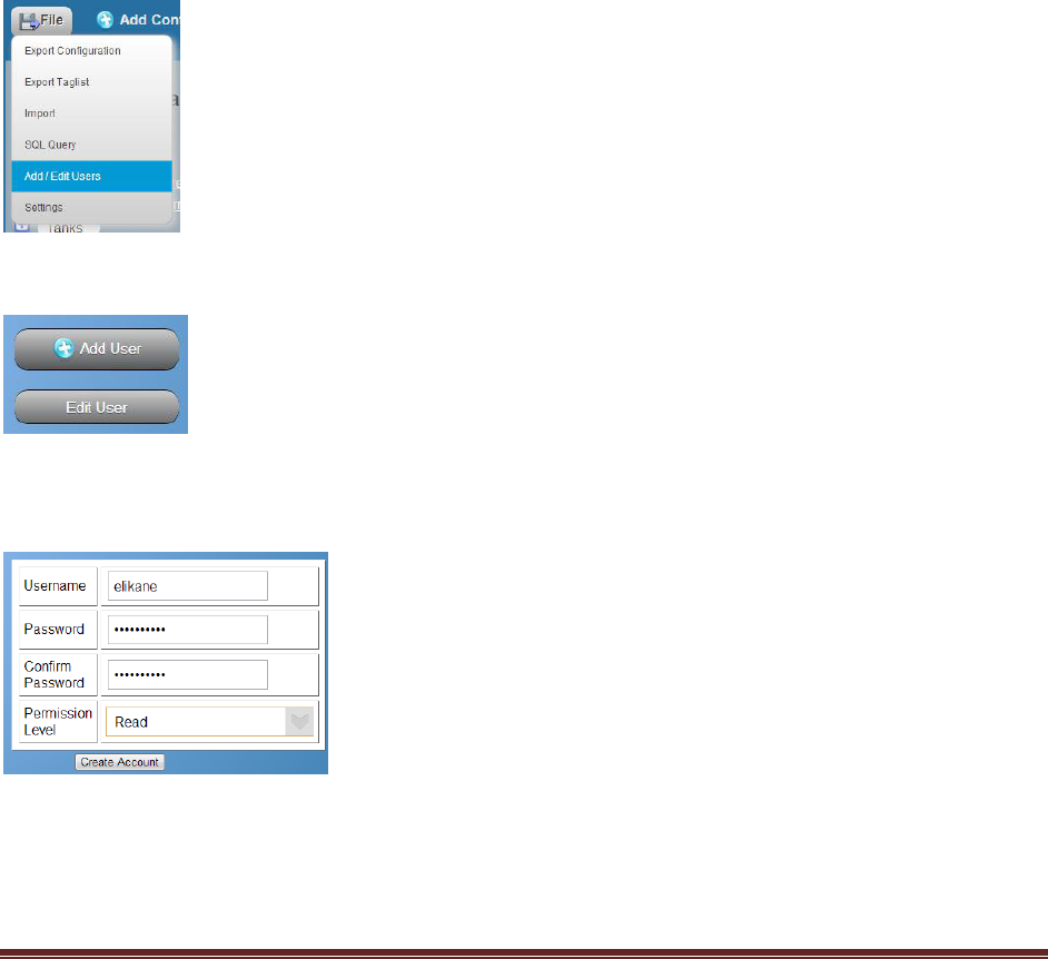
PROVue™ User Accounts
The PROVue display maintains a set of user accounts. As supplied from the factory, there is only one
account, “admin”. The password for this account is “default” (without the quotes on either, of course).
The admin account has full access to the PROVue display, and can modify the configuration as well as
create, edit and delete other users.
There are three levels of access. Read, Read/Write and Client Admin. It is strongly recommended that
the end user create a new Client Admin level account. Once a new Client Admin account has been
created, the original “admin” account deactivates. This will prevent accidental or idle fiddling in the field
from causing damage to configurations and operations.
To add an account, select the Add User menu selection from the page File menu header.
A new Add User / Edit User pair of buttons will appear in the right hand panel. Select Add User.
A new user dialog will appear in the right hand panel. Edit it as needed and click the Create Account
button.
The users added here are used both in the web interface login and on the PROVue display itself. You
can use the web interface to edit existing users. An almost unlimited number of users can be added to
the PROVue.
PROVue Manual V 1.2.5979
Page 34
PROVue™ WiFi Access Point
The PROVue has a built in WiFi Access Point. It can be turned on and off by an administrator. By
default, the SSID is PADPro and the password is flowdata. Any device capable of connecting to a WiFi
hot spot or access point can connect to the PROVue. Use of the wireless access to the network is not
restricted to configured users of the PROVue in release version 1.0. This means that anyone that
connects successfully to the access point has access to the network that the PROVue is attached to. This
does not grant uncontrolled access to the PROVue itself. Access to it is still controlled by the PROVue
user access login control and will require a user to log in to it.
To turn the Access Point on or off, use the Settings applet form the front panel. You must be
logged in as an administrator to do this.
Once you have connected to the Access Point, you can use your web browser to connect to the PROVue
and log in to the Application Setup interface. The default address for the PROVue through the WiFi is
192.168.43.1:8080. See Figure 20 below. Connection to the PROVue through the physical Ethernet
connection uses a different IP address.
Figure 25 - WiFi Web Interface IP Address is shown – the physical address is 10.147.160.100:8080
See the PROVue Web Interface section for information on how to use the Web Interface for operational
data and configuration.

PROVue Manual V 1.2.5979
Page 35
Maintenance
Under normal operation, the only maintenance required is to keep the screen clean. Wiping with a dry
lint free cloth to remove dust and finger prints will improve the touch screen response to user input.
If the unit becomes non-operational, the removal and installation instructions above should be followed.
The sun shield should be lowered over the screen when not in use. Failure to keep the screen shielded
may result in premature failure of the LCD or the touch screen interface.
Troubleshooting
The front panel button serves as the Android™ “back button”. If the display fails to turn on when this is
pressed, ensure that the Molex connector that supplies the PROVue with power and interface
connections is firmly seated.
Check to make sure that power is supplied to the unit. Normal operation requires 7 to 14 VDC, with 12
VDC optimal.
If the display powers on but does not respond to touch, make sure that the screen is free from dust,
grease and other dirt. Use a soft lint free cloth to gently wipe the screen clean.
If the interface seems responsive to user input, but the operation of the PADPro seems incorrect, the
problem is likely with the configuration or instrumentation that provide the solution, and not with the
PROVue LOI itself. Refer to the PadManager and PADPro documentation for further assistance.

PROVue Manual V 1.2.5979
Page 36
Specifications
PROVue:
Temperature range: -20° C to +70° C (-4° F to +158° F) operational
Voltage: +7 to +14 VDC
Power: 6 Watts
Ratings: The unit is IP 54 rated per IEC 60529 requirements
Contact
For assistance or further information, contact Flow Data, Inc.
24/7 Help line: 970-523-7744
Email: support@flow-data.com
Web: http://support.flow-data.com
Address:
Flow Data, Inc.
2309 Grand Park Dr.
Grand Junction, CO 81521

PROVue Manual V 1.2.5979
Page 37
Class 1 Div 2 Statement
Clause 16 of ANSI/ISA 12.12.01
16.2 The PROVue is suitable for use in Class 1, Division 2 groups C and D, T4, or unclassified locations.
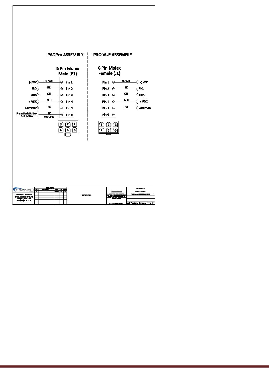
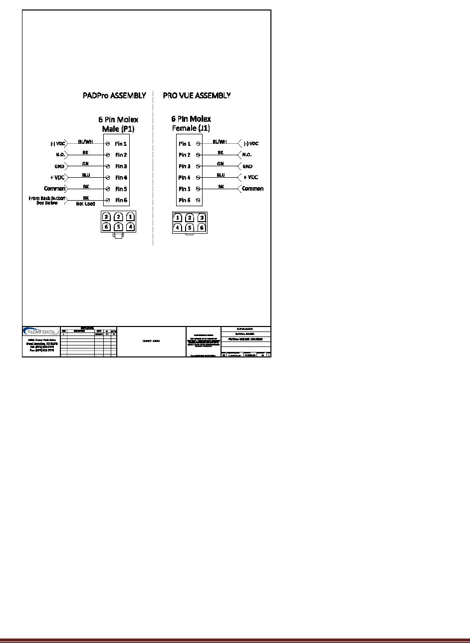
16.3 Refer to Diagram 1. The PROVue wiring harness is a component supplied inside the PADPro panel,
and is not a component of the PROVue. In the diagram, J1 is the female connection that is part of the
PROVue assembly. From the harness, P1 is the male plug that mates with J1 to provide power and
connection to a front panel button, also not part of the PROVue assembly.
Note that J1-4 is connected to positive VDC and that J1-1 is connected to the power supply common
(negative). J1-3 is connected to equipment ground inside the PROVue assembly, and through P1-3 is
then connected to the PADPro chassis ground, which is tied to VDC common and earth ground.
J1-2 and J-5 are connected through P1-2 and P1-5 to a button on the front panel which provides a dry
contact switch closure for signaling the PROVue. There is no polarity associated with this connection.
PROVue Manual V 1.2.5979
Page 38
Diagram 1 - Wiring harness detail (16.3)
16.4 N.A.
16.5.1 N.A.
16.5.2
WARNING: EXPLOSION HAZARD. DO NOT DISCONNECT WHILE THE CIRCUIT IS LIVE OR
UNLESS THE AREA IS KNOWN TO BE FREE OF IGNITIBLE CONCENTRATIONS.
16.5.3 N.A.
16.6 N.A.

PROVue Manual V 1.2.5979
Page 39
16.2 Cet PROVue peut être utilisé en classe 1, des groupes de la Division 2, C une D, T4, ou
emplacements non classifiés.
16.3 Se référer au schéma de câblage suivant. Le faisceau de câblage PROVue est un composant fourni
à l'intérieur de la PADPro et n'est pas un composant de la PROVue. Dans le diagramme, J1 est
l'accouplement qui appartient à l'Assemblée PROVue. Du faisceau, P1 est le mâle qui s'accouple avec J1
pour fournir l'alimentation et le raccordement à un bouton du panneau avant, aussi ne fait pas partie de
l'Assemblée PROVue de brancher.
Notez que J1-4 est connecté au VCC positif et que J1-1 est associé à la puissance d'alimentation
common (négatif). J1-3 est raccordé à la terre de l'équipement à l'intérieur de l'Assemblée PROVue et à
P1-3 est alors connecté à la masse du véhicule PADPro, qui est relié aux VDC commun et mise à la
terre.
J1-2 et J-5 sont reliés par 2 P1 et P1-5 à un bouton sur le panneau frontal qui permet une fermeture de
l'interrupteur de contact sec pour la signalisation du PROVue. Il n'y a pas de polarité associée à cette
connexion.
PROVue Manual V 1.2.5979
Page 40
16.4 Ne s'applique pas
16.5.1 Ne s'applique pas
16.5.2
AVERTISSEMENT : RISQUE D'EXPLOSION. NE DÉCONNECTEZ PAS ALORS QUE LE CIRCUIT EST
SOUS TENSION OU À MOINS QUE LA ZONE EST CONNUE POUR ÊTRE LIBRE DES
CONCENTRATIONS INFLAMMABLE.
16.5.3 Ne s'applique pas
16. Ne s'applique pas

PROVue Manual V 1.2.5979
Page 41
FCC/IC Statement
Wi-Fi Broadband:
Standards: 802.11 n, g, and b 2.4 GHz
Power Levels: 18 dBm max transmitted from Wi-Fi unit.
Antenna: 3 dBi max type RP SMA
Certifications:
FCC ID: ST7-PROVUE
ID: 11071A-PROVUE
FCC Part 15.247, Subpart C
FCC Part 15.21
Any changes or modifications to this equipment not expressly approved by Flow Data could void the
users’ authority to operate this equipment under FCC Part 15 rules.
FCC Part 15.105
Note: This equipment has been tested and found to comply with the limits for a Class A digital device,
pursuant to part 15 of the FCC Rules. These limits are designed to provide reasonable protection against
harmful interference when the equipment is operated in a commercial environment. This equipment
generates, uses, and can radiate radio frequency energy and, if not installed and used in accordance with
the instruction manual, may cause harmful interference to radio communications. Operation of this
equipment in a residential area is likely to cause harmful interference in which case the user will be
required to correct the interference at his own expense.
IC RSS-210, Issue 8
Under Industry Canada regulations, this radio transmitter may only operate using an antenna of a type
and maximum (or lesser) gain approved for the transmitter by Industry Canada. To reduce potential radio
interference to other users, the antenna type and its gain should be so chosen that the equivalent
isotropically radiated power (e.i.r.p.) is not more than that necessary for successful communication.
Conformément à la réglementation d'Industrie Canada, le présent émetteur radio peut fonctionner avec
une antenne d'un type et d'un gain maximal (ou inférieur) approuvé pour l'émetteur par Industrie
Canada. Dans le but de réduire les risques de brouillage radioélectrique à l'intention des autres
utilisateurs, il faut choisir le type d'antenne et son gain de sorte que la puissance isotrope rayonnée
équivalente (p.i.r.e.) ne dépasse pas l'intensité nécessaire à l'établissement d'une communication
satisfaisante.

PROVue Manual V 1.2.5979
Page 42
RSS-GEN Issue 3 §7.1.2
English
French
This device complies with Industry Canada licence-
exempt RSS standard(s). Operation is subject to the
following two conditions: (1) this device may not cause
interference, and (2) this device must accept any
interference, including interference that may cause
undesired operation of the device.
Le présent appareil est conforme aux CNR d'Industrie
Canada applicables aux appareils radio exempts de
licence. L'exploitation est autorisée aux deux conditions
suivantes : (1) l'appareil ne doit pas produire de
brouillage, et (2) l'utilisateur de l'appareil doit accepter
tout brouillage radioélectrique subi, même si le
brouillage est susceptible d'en compromettre le
fonctionnement.
RSS-GEN Issue 3 §7.1.2
English
French
This radio transmitter 11071A-PROVUE has been
approved by Industry Canada to operate with the
antenna types listed below with the maximum
permissible gain and required antenna impedance for
each antenna type indicated. Antenna types not included
in this list, having a gain greater than the maximum
gain indicated for that type, are strictly prohibited for
use with this device.
Le présent émetteur radio 11071A-PROVUE a été
approuvé par Industrie Canada pour fonctionner avec
les types d'antenne énumérés ci-dessous et ayant un gain
admissible maximal et l'impédance requise pour chaque
type d'antenne. Les types d'antenne non inclus dans cette
liste, ou dont le gain est supérieur au gain maximal
indiqué, sont strictement interdits pour l'exploitation de
l'émetteur.
Antenna: 3 dBi max type RP SMA