Flow Asco 8344 Series Poppet Valve 1505490833 User Manual
Asco 8344 Series Poppet Valve-1505490833 ASCO_8344_SERIES_POPPET_VALVE-1505490833
2017-10-06
User Manual: Flow Asco 8344 Series Poppet Valve-1505490833
Open the PDF directly: View PDF ![]() .
.
Page Count: 4
Standard
Coil and
Class of
Insulation
Watt Rating and Power
Consumption Spare Coil Part Number
DC
Watts
AC General Purpose Explosionproof
Watts
VA
Holding
VA
Inrush AC DC AC DC
F 10.6 6.1 16 30 238210 238310 238214 238314
F 11.6 10.1 25 50 238610 238710 238614 238714
F 22.6 17.1 40 70 238610 238710 238614 238714
Dual Solenoid Operation: Minimum coil on-time for dual solenoid valves is 0.3
seconds on air service and 1.0 seconds on liquids.
Caution: Do not energize both solenoids simultaneously.
Refer to Engineering Section for details.
Standard Voltages: 24, 120, 240, 480 volts AC, 60 Hz (or 110, 220 volts AC, 50 Hz).
6, 12, 24, 120, 240 volts DC. Must be specified when ordering.
Other voltages are available when required.
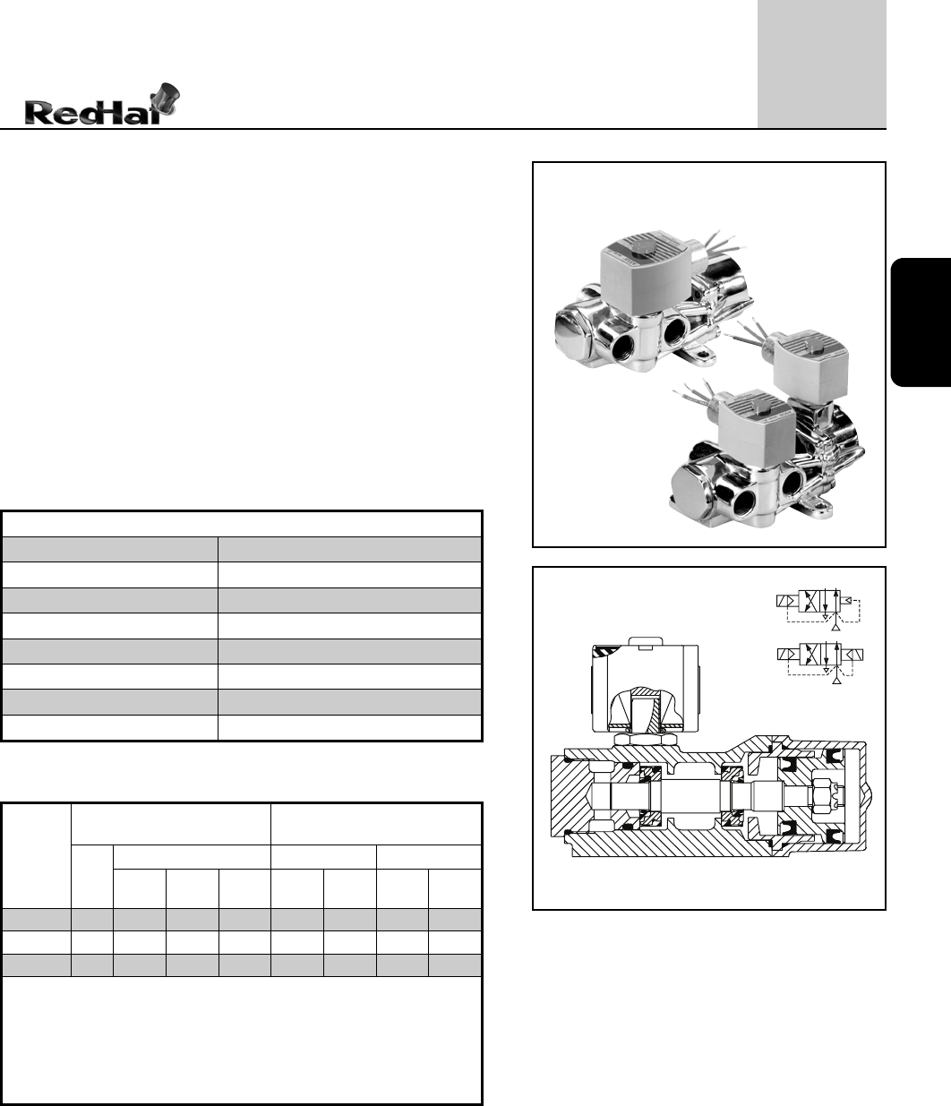
4/2
SERIES
8344
4-WAY
4
% )
Features
• Sturdy, robust construction
• Piston-operated poppet design provides high flow
• For use with air or water
• Wide range of sizes and flow rates
• Single or dual solenoid constructions
• Dual solenoid can be shifted with a momentary
signal and remain in position even if electrical
power is lost
• Mountable in any position
Pilot Operated
Piston/Poppet Solenoid Valves
Brass Body • 1/4" to 1" NPT
B
E
A
P
B
E
A
P
Solenoid Enclosures
Electrical
Nominal Ambient Temp. Ranges
AC: 32˚F to 125˚F (0˚C to 52˚C)
DC: 32˚F to 104˚F (0˚C to 40˚C)
Refer to Engineering Section for details.
Approvals
CSA certified. Meets applicable CE directives.
Important
A Minimum Operating Pressure Differential must be
maintained between the pressure and exhaust ports.
Supply and exhaust piping must be full area, unrestricted.
ASCO flow controls and other similar components must
be installed in the cylinder lines only.
• Loss of air pressure may allow valve to shift on dual
solenoid constructions.
Standard: Watertight, Types 1, 2, 3, 3S, 4, and 4X.
Optional: Explosionproof and Watertight, Types 3, 3S, 4, 4X, 6, 6P, 7, and 9.
(To order, add prefix “EF” to the catalog number.)
See Optional Features Section for other available options.
Construction
89
Valve Parts in Contact with Fluids
Body Brass
Seals and Disc NBR
Core Tube 305 Stainless Steel
Core and Plugnut 430F Stainless Steel
Springs 302 Stainless Steel / 17-7PH Stainless Steel
Shading Coil Copper
Pilot Seat Cartridge and Disc-Holder CA
Shaft Gasket PA
4/2
SERIES
8344 4
4-WAY
90
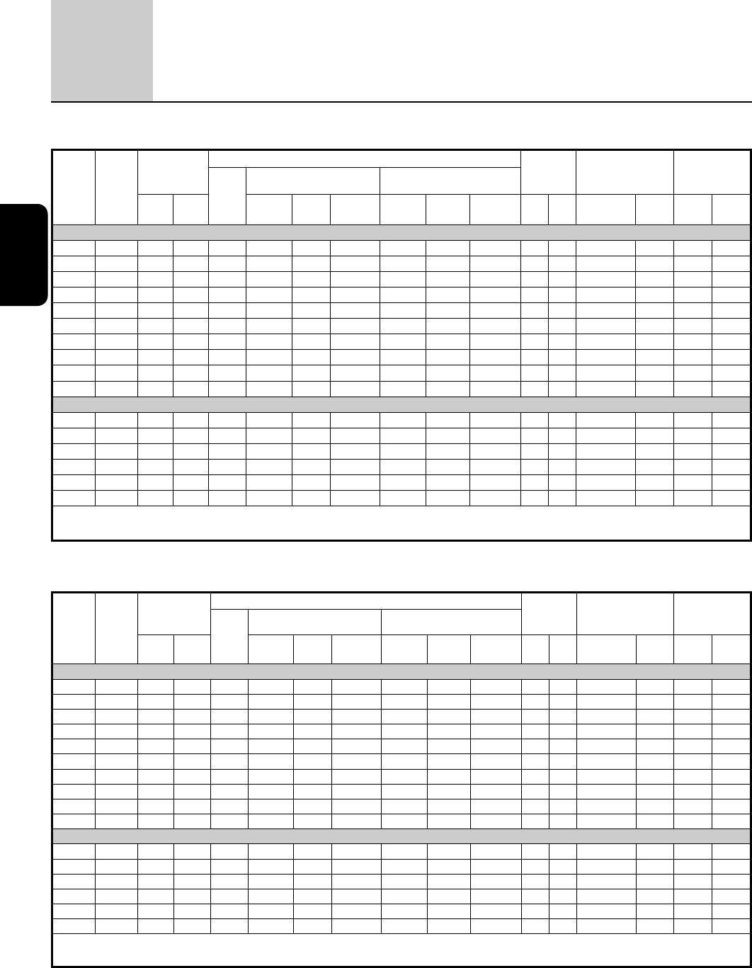
Specifications (Metric units)
Specifications (English units)
Pipe
Size
(in)
Orifice
Size
(in)
Cv Flow
Factor
Operating Pressure Differential (psi) Max.
Fluid
Temp.˚F Brass Body
Watt Rating/
Class of Coil
Insulation
Min.
Max. AC Max. DC
Press. Exh.
Air-Inert
Gas
Water
Lt. Oil @
300 SSU
Air-Inert
Gas
Water
Lt. Oil @
300 SSU AC DC
Catalog
Number
Const.
Ref. AC DC
SINGLE SOLENOID
1/4 1/4 .80 1.0 10 150 125 125 125 125 125 180 150 8344G070 1 10.1/F 11.6/F
1/4 1/4 .80 1.0 10 250 250 250 250 250 250 180 180 8344G000 1 17.1/F 22.6/F
3/8 3/8 1.4 2.2 10 150 125 125 125 125 125 180 150 8344G072 2 10.1/F 11.6/F
3/8 1/4 .80 1.0 10 250 250 250 250 250 250 180 180 8344G001 1 17.1/F 22.6/F
1/2 3/8 1.4 2.2 10 150 125 125 125 125 125 180 150 8344G074 2 10.1/F 11.6/F
1/2 3/8 1.4 2.2 10 250 250 250 250 250 250 180 180 8344G027 2 17.1/F 22.6/F
3/4 3/4 5.2 5.6 10 150 125 125 125 125 125 180 150 8344G076 3 10.1/F 11.6/F
3/4 3/4 5.2 5.6 10 250 250 250 250 250 250 180 180 8344G029 3 17.1/F 22.6/F
13/4 5.2 5.6 10 150 125 125 125 125 125 180 150 8344G078 3 10.1/F 11.6/F
13/4 5.2 5.6 10 250 250 250 250 250 250 180 180 8344G031 3 17.1/F 22.6/F
DUAL SOLENOID
1/4 1/4 .80 1.0 10 250 200 125 125 125 100 180 120 8344G044 4 6.1/F 10.6/F
3/8 3/8 1.4 2.2 10 250 200 125 125 125 100 180 120 8344G080 6 6.1/F 10.6/F
3/8 3/8 1.4 2.2 10 300 300 200 - - - 180 - 8344G050 7 10.1/F -
1/2 3/8 1.4 2.2 10 250 200 125 125 125 100 180 120 8344G082 6 6.1/F 10.6/F
3/4 3/4 5.2 5.6 10 300 300 200 125 125 100 180 120 8344G054 8 10.1/F 10.6/F
13/4 5.2 5.6 10 300 300 200 125 125 100 180 120 8344G056 8 10.1/F 10.6/F
25 psi (1.7 bar) minimum on light oil service. For best results, do not use valve rated 250 psi (17 bar) on mainline pressure of less than 125 psi (9 bar).
On 50 hertz service, the watt rating for the 6.1/F solenoid is 8.1 watts. Water rating, CSA certified up to 232 psi.
Pipe
Size
(in)
Orifice
Size
(mm)
Kv Flow
Factor (m3/h)
Operating Pressure Differential (bar) Max.
Fluid
Temp.˚C Brass Body
Watt Rating/
Class of Coil
Insulation
Min.
Max. AC Max. DC
Press. Exh.
Air-Inert
Gas
Water
Lt. Oil @
300 SSU
Air-Inert
Gas
Water
Lt. Oil @
300 SSU AC DC
Catalog
Number
Const.
Ref. AC DC
SINGLE SOLENOID
1/4 6 .69 .86 0.7 10 9 9 9 9 9 82 65 8344G070 1 10.1/F 11.6/F
1/4 6 .69 .86 0.7 17 17 17 17 17 17 82 82 8344G000 1 17.1/F 22.6/F
3/8 10 1.2 1.89 0.7 10 9 9 9 9 9 82 65 8344G072 2 10.1/F 11.6/F
3/8 6 .69 .86 0.7 17 17 17 17 17 17 82 82 8344G001 1 17.1/F 22.6/F
1/2 10 1.2 1.89 0.7 10 9 9 9 9 9 82 65 8344G074 2 10.1/F 11.6/F
1/2 10 1.2 1.89 0.7 17 17 17 17 17 17 82 82 8344G027 2 17.1/F 22.6/F
3/4 19 4.5 4.80 0.7 10 9 9 9 9 9 82 65 8344G076 3 10.1/F 11.6/F
3/4 19 4.5 4.80 0.7 17 17 17 17 17 17 82 82 8344G029 3 17.1/F 22.6/F
1 19 4.5 4.80 0.7 10 9 9 9 9 9 82 65 8344G078 3 10.1/F 11.6/F
1 19 4.5 4.80 0.7 17 17 17 17 17 17 82 82 8344G031 3 17.1/F 22.6/F
DUAL SOLENOID
1/4 6 .80 .86 0.7 17 14 9 9 9 7 82 49 8344G044 4 6.1/F 10.6/F
3/8 10 1.4 1.89 0.7 17 14 9 9 9 7 82 49 8344G080 6 6.1/F 10.6/F
3/8 10 1.4 1.89 0.7 21 21 14 - - - 82 - 8344G050 7 10.1/F -
1/2 10 1.4 1.89 0.7 17 14 9 9 9 7 82 49 8344G082 6 6.1/F 10.6/F
3/4 19 5.2 4.80 0.7 21 21 14 9 9 7 82 49 8344G054 8 10.1/F 10.6/F
1 19 5.2 4.80 0.7 21 21 14 9 9 7 82 49 8344G056 8 10.1/F 10.6/F
25 psi (1.7 bar) minimum on light oil service. For best results, do not use valve rated 250 psi (17 bar) on mainline pressure of less than 125 psi (9 bar).
On 50 hertz service, the watt rating for the 6.1/F solenoid is 8.1 watts. Water rating, CSA certified up to 16 bar.
4/2
SERIES
8344
4
4-WAY
91
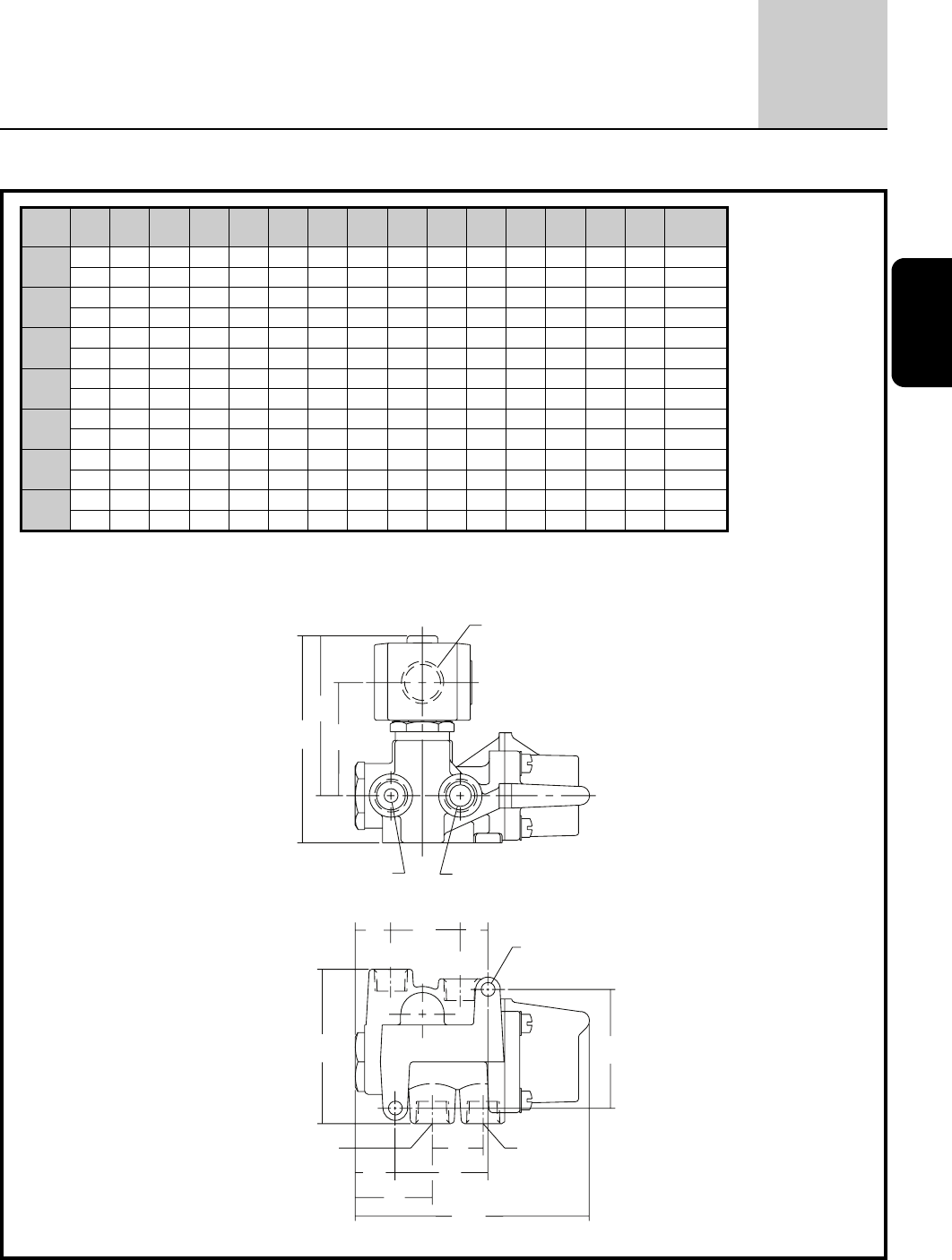
Dimensions inches (mm)
1/2 NPT
PRESS EXH.
H
P
K
NXE
PRESS EXH.
2 MTG. HOLES
DIA “D”
F
CYL A
W
Y
Z
J
G
CYL B
L
Const. Ref 1 - 3
Const.
Ref. ØD E F G H J K L N P W X Y Z
Exhaust
Pipe Size
1in Ø .28 .56 2.41 1.88 4.08 1.03 2.15 3.13 .72 3.12 4.75 1.41 1.56 .81 3/8
mm Ø 7.1 14 61 48 104 26 55 80 18 79 121 36 40 21 3/8
2in Ø .34 .75 3.12 2.63 4.06 1.50 1.97 3.18 .83 2.94 6.06 1.88 1.90 .84 1/2
mm Ø 8.6 19 79 67 103 38 50 81 21 75 154 47 48 21 1/2
3in Ø .34 1.34 3.81 3.88 4.86 2.09 2.34 4.56 1.56 3.31 8.25 2.12 2.63 1.16 1
mm Ø 8.6 34 97 99 123 53 59 116 39 84 210 54 67 30 1
4in Ø .28 .56 2.41 1.88 4.34 1.03 2.52 3.13 .72 3.38 4.81 1.41 1.56 .81 3/8
mm Ø 7.1 14 61 48 110 26 64 80 18 86 122 36 40 21 3/8
6in Ø .34 .75 3.12 2.63 4.50 1.50 2.52 3.18 .83 3.38 6.06 1.88 1.90 .84 1/2
mm Ø 8.6 19 79 67 114 38 64 81 21 86 154 47 48 21 1/2
7in Ø .34 .75 3.12 2.63 4.68 1.50 2.59 3.18 .83 3.56 6.06 1.88 1.90 .84 1/2
mm Ø 8.6 19 79 67 119 38 66 81 21 90 154 47 48 21 1/2
8in Ø .34 1.34 3.81 3.88 5.56 2.09 3.03 4.56 1.55 4.00 8.25 2.12 2.63 1.16 1
mm Ø 8.6 34 97 99 141 53 77 116 39 102 210 54 67 30 1

4/2
SERIES
8344 4
4-WAY
92
Dimensions inches (mm)
1/2 NPT
PRESS EXH.
K
P
H
NXE
PRESS EXH.
2 MTG. HOLES
DIA “D”
F
CYL A
W
Y
Z
J
G
CYL B
L
Const. Ref. 4 - 8
