Flow Fabco Air Directional Control Valves 1505490940 User Manual
Fabco-Air Directional Control Valves-1505490940 FABCO-AIR_DIRECTIONAL_CONTROL_VALVES-1505490940
2017-10-06
User Manual: Flow Fabco-Air Directional Control Valves-1505490940
Open the PDF directly: View PDF ![]() .
.
Page Count: 32

Specifi cations subject to change without notice or incurring obligation
Directional Control Valves
11
11.1 2-18-08
Port Flow Rate/ Function Series Actuators Page Number
Size Factor
10-32 Cv = 0.05 2 Way Modular Solenoid 11.3 - 11.4
& to 3 Way Manifold
1/8 NPT Cv = 0.23 4 Way, 2 Position
Modular
1/8 NPT Cv = 0.05 2 Way Hex Solenoid 11.5–11.6
& to 3 Way Body
1/4 NPT Cv = 0.23
1/8 NPT Cv = 0.27 2 Way 18 Manual 11.7-11.8
3 Way Mechanical 11.7-11.8
4 Way, 2 Position Pilot 11.7-11.8
Solenoid 11.9-11.12
1/4 NPT Cv = 1.0 3 Way 14 Manual 11.13-11.16
4 Way, 2 Position Mechanical 11.13-11.14
4 Way, 3 Position Pilot 11.13-11.15
Solenoid 11.17-11.22
1/4 NPT Cv = 1.0 3 Way M14 Manual 11.13
Stacking 4 Way, 2 Position Mechanical 11.13
Pilot 11.13
Solenoid 11.20
3/8 NPT Cv = 1.0 3 Way 34 Manual 11.13-11.16
4 Way, 2 Position Mechanical 11.13-11.14
4 Way, 3 Position Pilot 11.13-11.15
Solenoid 11.17-11.22
3/8 NPT Cv = 2.2 3 Way 12A Manual 11.23-11.28
& to 4 Way, 2 Position Pilot
1/2 NPT Cv = 3.9 4 Way, 3 Position Solenoid
Manifold
3/8 NPT Cv = 2.4 3 Way 38 Manual 11.23–11.28
to 4 Way, 2 Position Pilot
Cv = 4.1 4 Way, 3 Position Solenoid
1/2 NPT Cv = 2.4 3 Way 12 Manual 11.23–11.28
to 4 Way, 2 Position Pilot
Cv = 4.1 4 Way, 3 Position Solenoid
1/2 NPT Cv = 6.2 3 Way 12B Manual 11.23–11.28
High Flow 4 Way, 2 Position Pilot
Solenoid
Section 11 Index
Note: Operating Temperature references for 18 Series and 14 Series valves described on pages 11.8 and 11.14.
Standard catalog models are suitable for operation in intermittent low temperatures in a range of 0° to + 32 °F.
A custom aluminum spool may be substituted when long-term application temperatures are expected to be –40° to +32°F. These
should be limited to manual or mechanical actuation, not spring return. Consider that actuation force may exceed catalog specs and
that spring return models may not be reliable at these low temperatures. Please consult factory.
For long-term, continuous operation in a range of +150°F to +180°F, the Viton seal option can provide the benefi ts of reliable leak-free
operation and extended durability. For applications exceeding +180°F, please consult factory.
Specifi cations subject to change without notice or incurring obligation
11
Directional Control Valves
11.2
Section 11 Index
Series Quick Page No.
Modular Manifold . . . . . . . . . . . . . . . 11.3
Hex Body . . . . . . . . . . . . . . . . . . . . . 11.5
18 . . . . . . . . . . . . . . . . . . . . . . . . . . . 11.7
14 . . . . . . . . . . . . . . . . . . . . . . . . . . . 11.13
M14. . . . . . . . . . . . . . . . . . . . . . . . . . 11.13
34 . . . . . . . . . . . . . . . . . . . . . . . . . . . 11.13
12A . . . . . . . . . . . . . . . . . . . . . . . . . . 11.23
38 . . . . . . . . . . . . . . . . . . . . . . . . . . . 11.23
12 . . . . . . . . . . . . . . . . . . . . . . . . . . . 11.23
12B . . . . . . . . . . . . . . . . . . . . . . . . . . 11.23
11-8-04
Specifi cations subject to change without notice or incurring obligation
Directional Control Valves
11
Modular Manifold
10-32 & 1/8 NPT
2, 3 & 4 Way
12-22-06
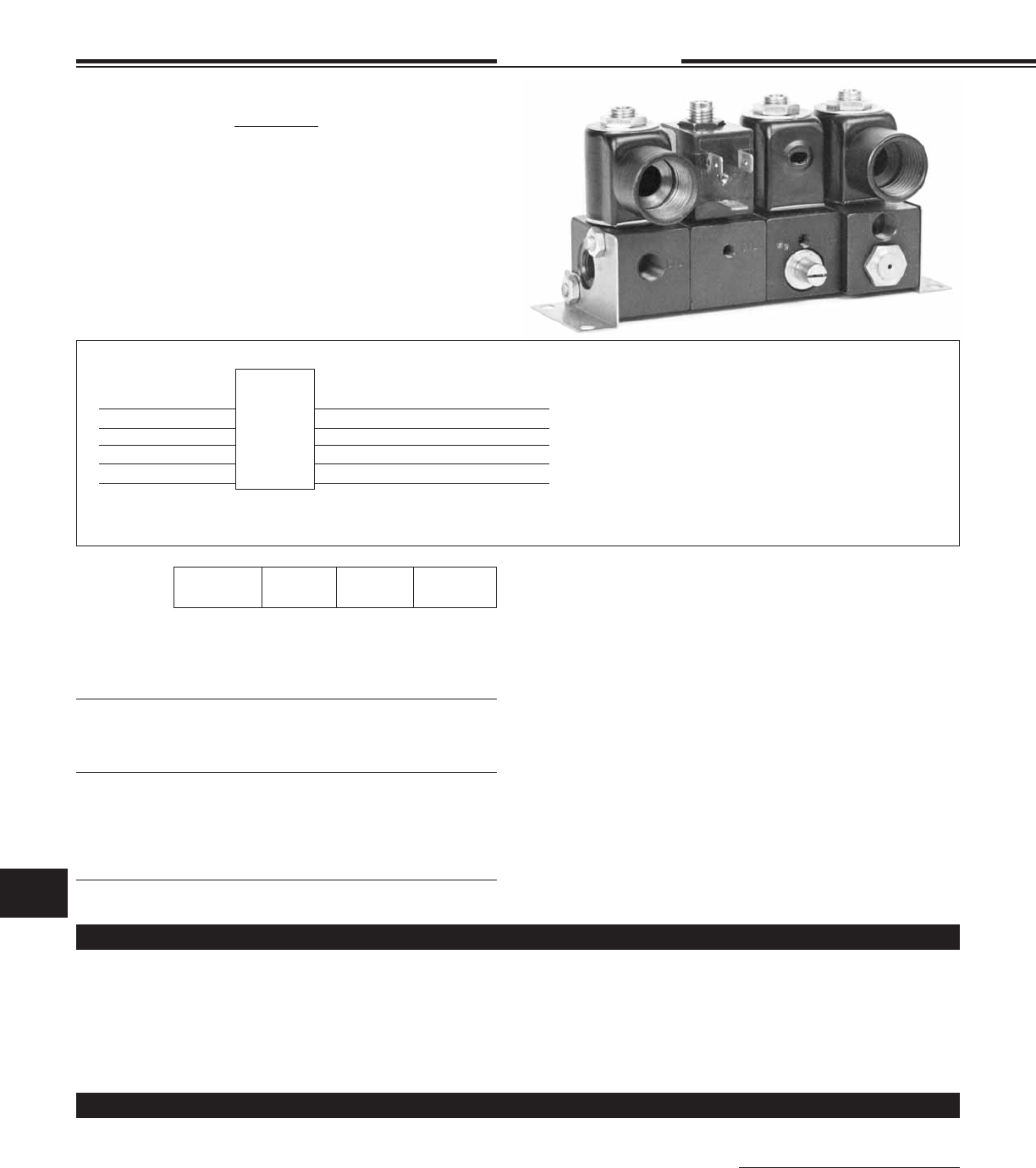
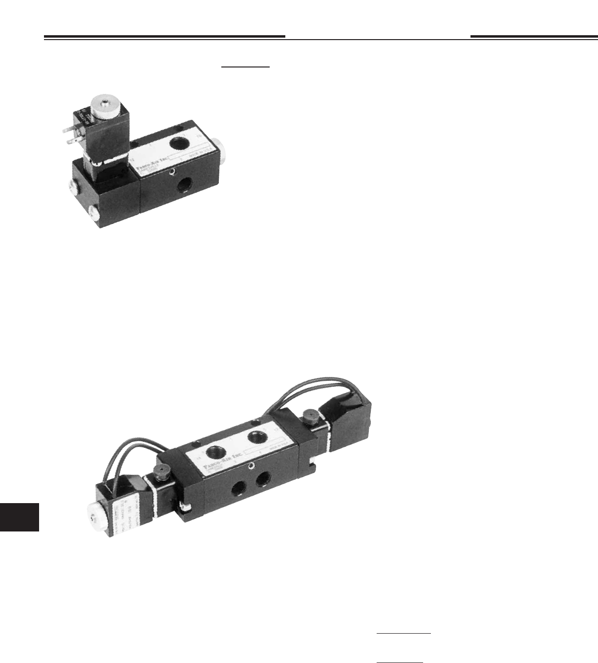
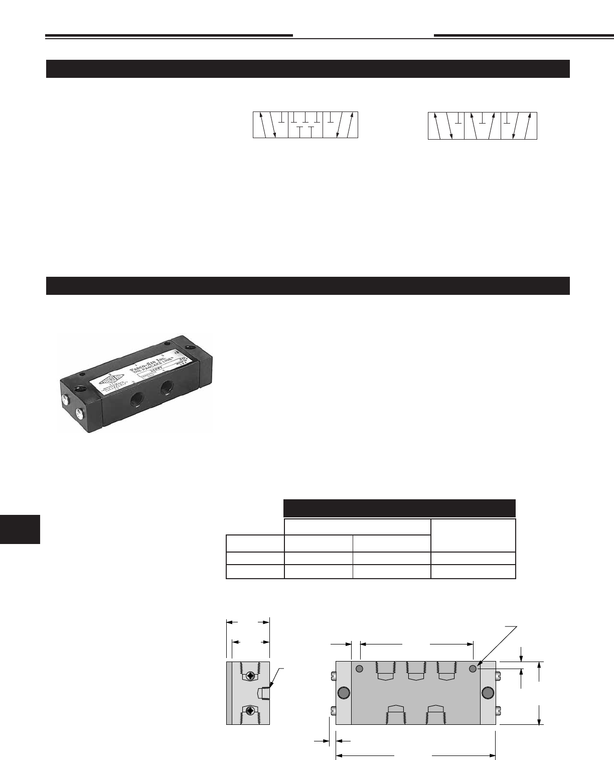
Miniature 53 STYLE Solenoid Valves
2, 3 or 4 Way - Modular Manifolding
2, 3 or 4 Way - Single Mounting
Time Proven • Space Saving • Reliable• 2, 3 and 4 Way Solenoid
Valves with 10-32 or 1/8 NPT ports are available in singular or modular
manifold versions. Any combination of function and ports can be combined
in the same manifold stack to save time, space and plumbing. With pressure
manifold plugging, two or more pressure ranges and/or medias can be
controlled in the same stack.
• Quantity of assembled Banks
• Valve models (start left to right, see photo above)
• Mounting brackets, if desired #101
Example… Using the photo above
1 Bank consisting of:
1 113-M-C-1 120/60
1 103-M-F-1 120/60
1 104-M-G-1 120/60
1 114-M-C-1 120/60
1 Pair #101 Mounting Brackets
For Complete Assembled Banks Specify:
Operating Pressures
Applies to all 4 Way 104 and 114 series valves.
See Orifi ce Information below for pressure ranges
of 2 & 3 Way valves.
STANDARD SPRING
40 psi Minimium
150 psi Maximum with #1, 3/64 orifi ce.
See Orifi ce Information below for Maximum with other orifi ces.
OPTIONAL LOW PRESSURE SPRING
20 psi:
20 psi Minimum
25 psi Maximum
25 psi:
25 psi Minimum
60 psi Maximum
Inlet Cylinder Basic
Function Port Port Model No.
Valves for 2 Way N.C. 1/8 NPT 1/8 NPT 112-S
Individual 3 Way N.C. 1/8 NPT 1/8 NPT 113-S
Mounting & 4 Way 10-32 10-32 104-S-10
Individual 4 Way 1/8 NPT 10-32 104-S-18
Inlet 4 Way 1/8 NPT 1/8 NPT 114-S
Valves for 2 Way N.C. 10-32 10-32 102-SM
Modular 3 Way N.C. 10-32 10-32 103-SM
Mounting &
Individual Inlet
Valves for 2 Way N.C. 1/8 NPT 10-32 102-M
Modular 2 Way N.C. 1/8 NPT 1/8 NPT 112-M
Mounting & 3 Way N.C. 1/8 NPT 10-32 103-M
Manifolded 3 Way N.C. 1/8 NPT 1/8 NPT 113-M
Inlet (Pressure 4 Way 1/8 NPT 10-32 104-M
Manifolded) 4 Way 1/8 NPT 1/8 NPT 114-M
All Mountings 3 Way Normally Open use 4 Way & Plug N.C. port
OPTION INFORMATION
ORIFICE INFORMATION
• Viton Seals for media compatibility specify Option -V
• Coils & Housing, See page 11.29.
• Low Pressure Spring - 4 Way Only - See Operating Pressures.
• Pro-Coat™ (Electroless Nickel Plate) Option -N, See page 1.10.
• Special Bank Assembly (Plugs, Fittings, Wire Terminals) See Pg iii.
• Normally Open (N.O.) 2 & 3 Way Valves -
Use 4 Way Valve & Plug N.C. Port.
Accessories
• Mounting Brackets Part # 101.
• Connectors for Mini-DIN “F”, See page 11.30.
• SM-10 Muffl er, See page 14.1.
CFM – Flow @
Cv Factor 2 Way N.C. 3 Way N.C. 4 Way 100 psi 50 psi
Number 0 1/32 .022 500 psi 200 psi 150 psi 1.3 0.9
Number 1 3/64 .055 400 150 150 3.5 2.0
Number 2 1/16 .075 200 100 100 5.8 3.4
Number 3 3/32 .156 100 60 80 9.0 6.0
Number 4 1/8 .230 75 30 Not Available Not Available 8.0
Available Orifi ces and Equivalent Maximum Pressure
Ratings for AC Voltages (DC Ratings Slightly Lower)
For Each Valve Specify:
EXAMPLE
Basic Model Number 103-M See Chart Below
Letter for Housing -C C Conduit, G Grommet, F DIN
Number for Seat -1 See orifi ce information chart below
Options See option Information below
Volts & Hertz 120/60 See solenoid information Page11.29
Example: 3 Way modular mounting with manifold inlet, 1/8 NPT inlet,
10-32 Cylinder Port, Conduit Housing, 3/64 Seat, 120 Volts/60 HZ.
Model Number = 103-M-C-1, 120/60
11.3
Specifi cations subject to change without notice or incurring obligation
11
Directional Control Valves Modular Manifold
10-32 & 1/8 NPT
2, 3 & 4 Way
5-3-12
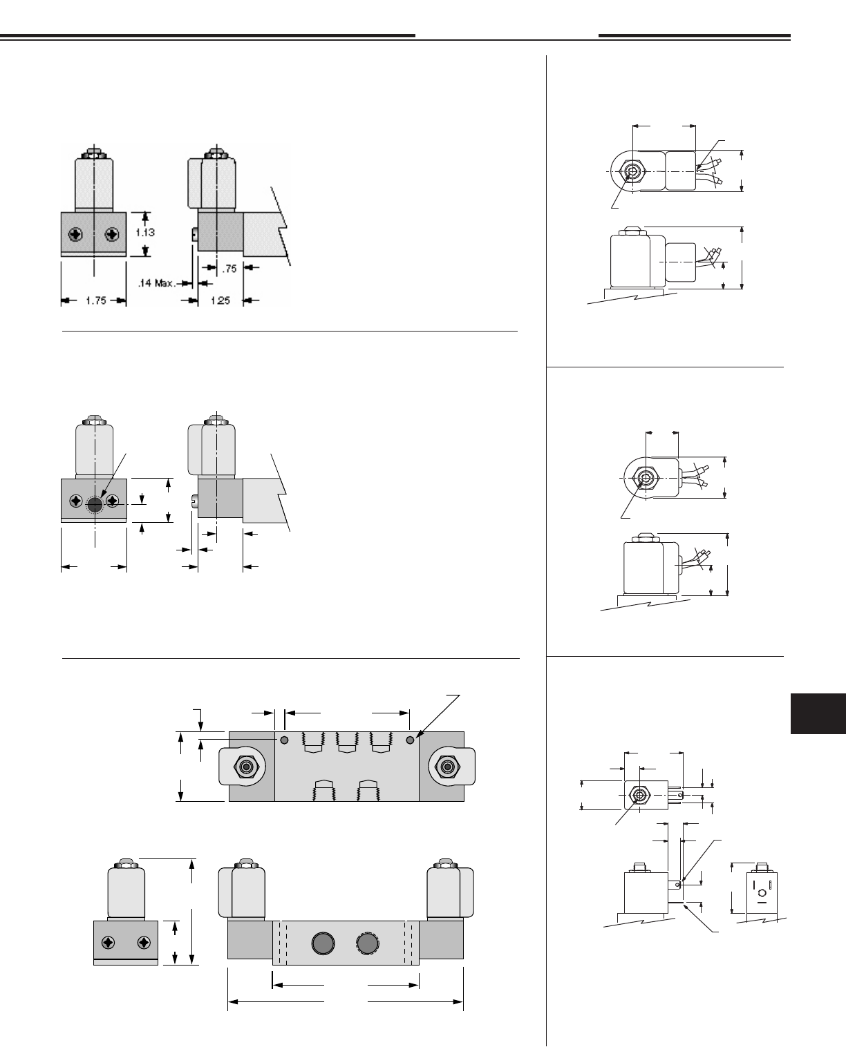
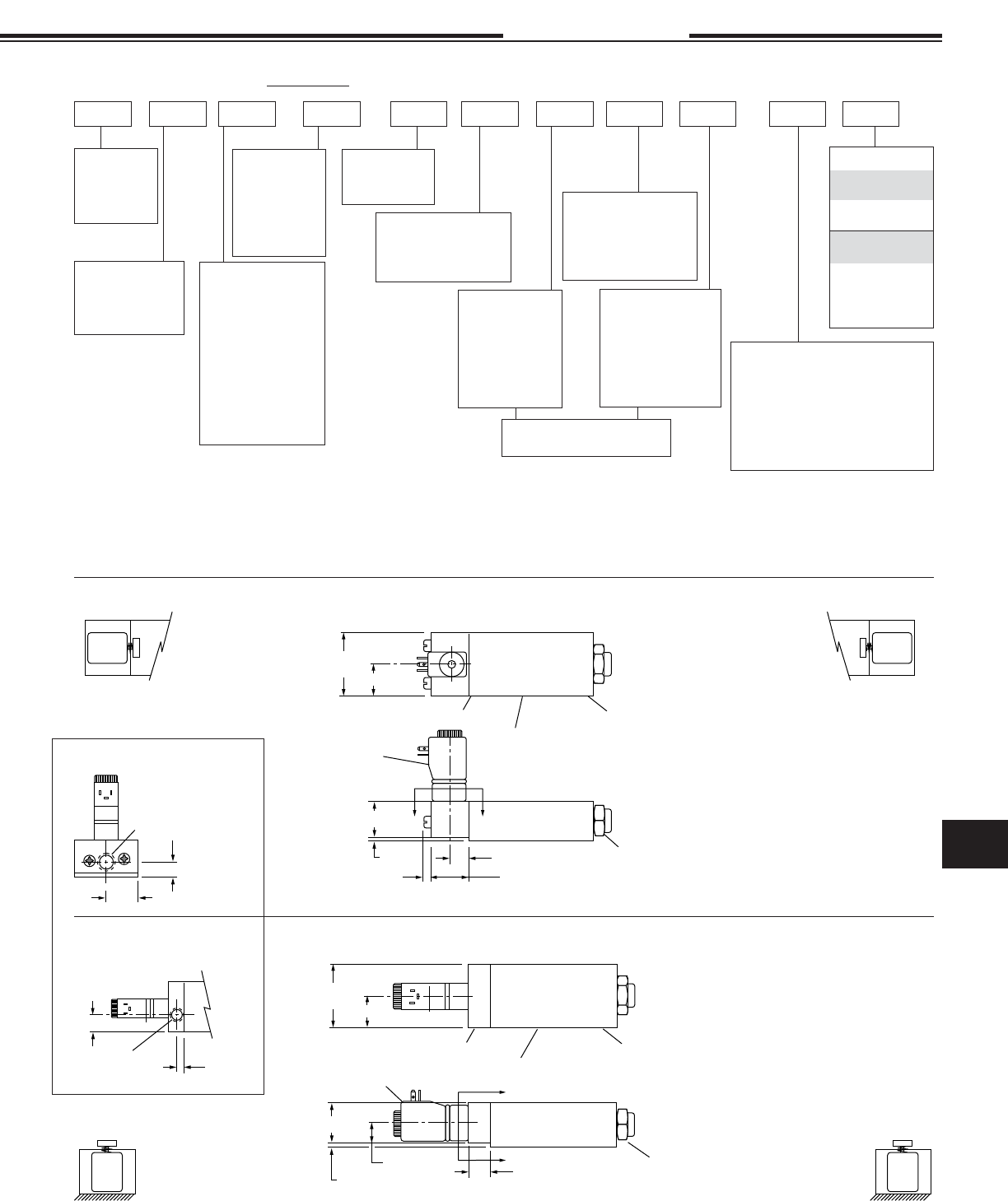
See Housing Details
on Page 11.29
1.13
Ty p .
.38
Ty p .
[ (Quantity of Valves) x 1.13] + .75
.56
Ty p .
1.38 Typ.
.83 Typ.
.19 Typ.
.19 Typ.
10-32 EXH Port
SM-10 Muffler,
See page 14.1.
.25
.03
.68
#101 Mounting Bracket (Pair)
2.80
.55 Typ.
1.02
.20 Dia.
4 Places
.55
.83
Dual Cylinder Ports
10-32 NC CYL Ports
102-M
.55
.83
Dual Cylinder Ports
10-32 NC CYL Ports
103-M
.21.21
.55
.83
10-32 NC CYL Port
104-M
.17
.24
10-32 NO CYL Port
.17
1.21
10-32 EXH Port
Do Not Restrict
Spring Cap
.55
.83
1/8 NPT CYL Port
112-M
.55 Ref.
.55
.83
1/8 NPT CYL Port
113-M
.10
.79
1.19
1/8 NPT NO CYL Port
114-M
.25
Spring
Cap
1/8 NPT NC CYL Port
.17
1.02
.36
10-32 EXH Port
Do Not Restrict
1.38
.22
.83
1.13
.78
.17
2.68
1.13
.78
.20 Dia. 2 Places.
Note: Mounting screw
heads may restrict
housing rotation.
See Housing Details on Page 11.29
Spring
Cap
10-32
NC CYL Port
10-32
EXH Port
.71
.55
.38
.83
.38
.56
10-32 NO CYL Port
10-32 EXH Port
Do Not Restrict
INLET PORT
104-S-10 10-32
104-S-18 1/8 NPT
1.81
.22
1.02
1.13
.78
.17
2.68
1.13
.91
.20 Dia. 2 Places.
Note: Mounting screw
heads may restrict
housing rotation.
See Housing Details on Page 11.29
Spring
Cap
1/8 NPT
NC CYL Port
10-32
EXH Port
.80
.55
.38
1.02
.17
.56
1/8 NPT NO CYL Port
10-32 EXH Port
Do Not Restrict
1.38
.22
.83
1.13
.78
.17
2.67
1.13
.55
.20 Dia. 2 Places.
Note: Mounting screw
heads may restrict
housing rotation.
See Housing Details on Page 11.29
10-32
EXH Port
.83
.56
1/8 NPT
112-S Cyl
113-S IN
1/8 NPT
112-S IN
113-S Cyl
See Housing Details
on Page 11.29
102-SM 103-SM
1.13
Ty p .
.38
Ty p .
[ (Quantity of Valves) x 1.13] + .75
.56
Ty p .
1.38 Typ.
.83 Typ.
.19 Typ.
.19 Typ.
10-32 10-32
10-32 IN Port (102-SM)
10-32 CYL Port (103-SM)
10-32 CYL Port 10-32 IN Port
10-32 EXH Port (103-SM)
2.80
.03 .89
.68
#101 Mounting Bracket (Pair)
.20 Dia.
4 Places
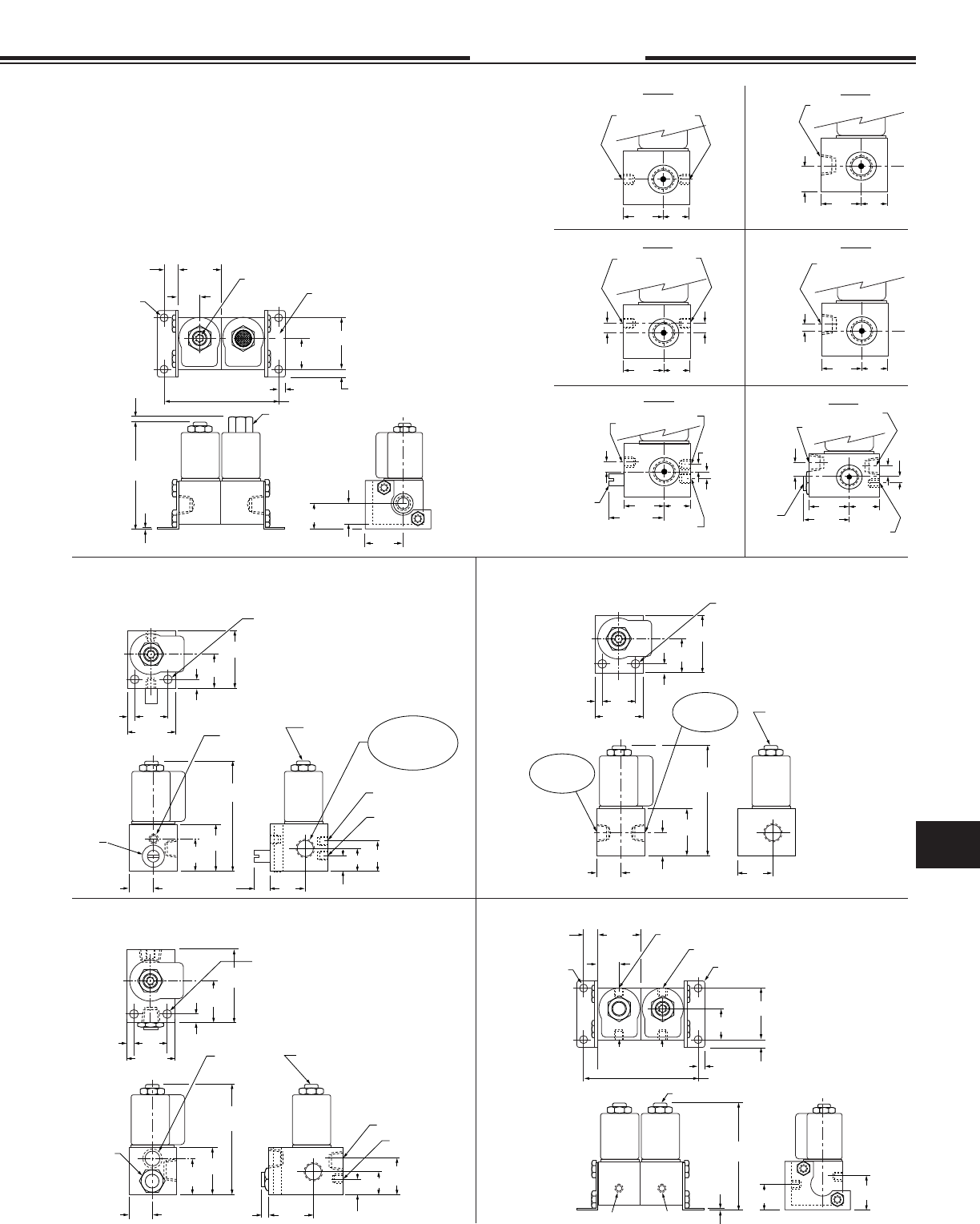
MODEL 114-S
MODELS 102-M, 103-M, 104-M, 112-M, 113-M & 114-M
Supply pressure can be connected to either or both ends of the stack. Due to
the fact that the supply pressure port on all “M” valve bodies is tapped on both sides,
the pressure manifold can be plugged at any point within the stack. This allows
you to supply the stack with two different pressures or media, one from each end.
For more than two inputs a port block can be provided in midstack. Spacers
can be included for applications requiring the larger EXPLOSION PROOF
operator. Contact Fabco-Air with your specifi c requirements.
MODEL 102-SM (2-Way), 103-SM (3-Way)
MODEL 104-S-10 (10-32 Inlet Port)
MODEL 104-S-18 (1/8 NPT Inlet Port)
MODEL 112-S (2-Way), 113-S (3-Way)
11.4
Specifi cations subject to change without notice or incurring obligation
Directional Control Valves
11
IN OUT Basic Model
1/8 10-32 X-82-★-✦-NO1
1/8 1/8 X-82-★-✦-NO2
1/4 10-32 X-42-★-✦-NO1
1/4 1/8 X-42-★-✦-NO2
IN OUT Basic Model
1/8 1/8 X-882-★-✦
1/8 1/4 X-482-★-✦
1/4 1/8 X-842-★-✦
1/4 1/4 X-442-★-✦
Hex Body
1/8 & 1/4 NPT
2 & 3 Way Valves
9-24-08
In
Out
In
Out
De-Energized Energized
In
Out
In
Out
De-Energized Energized
In
Out
In
Out
De-Energized Energized
In
Out
In
Out
De-Energized Energized
In
Out
In
Out
De-Energized Energized
In Out In Out
De-Energized Energized
Out
In
Out
In
De-Energized Energized
In
Out
In
Out
De-Energized Energized
In
Out
In
Out
De-Energized Energized
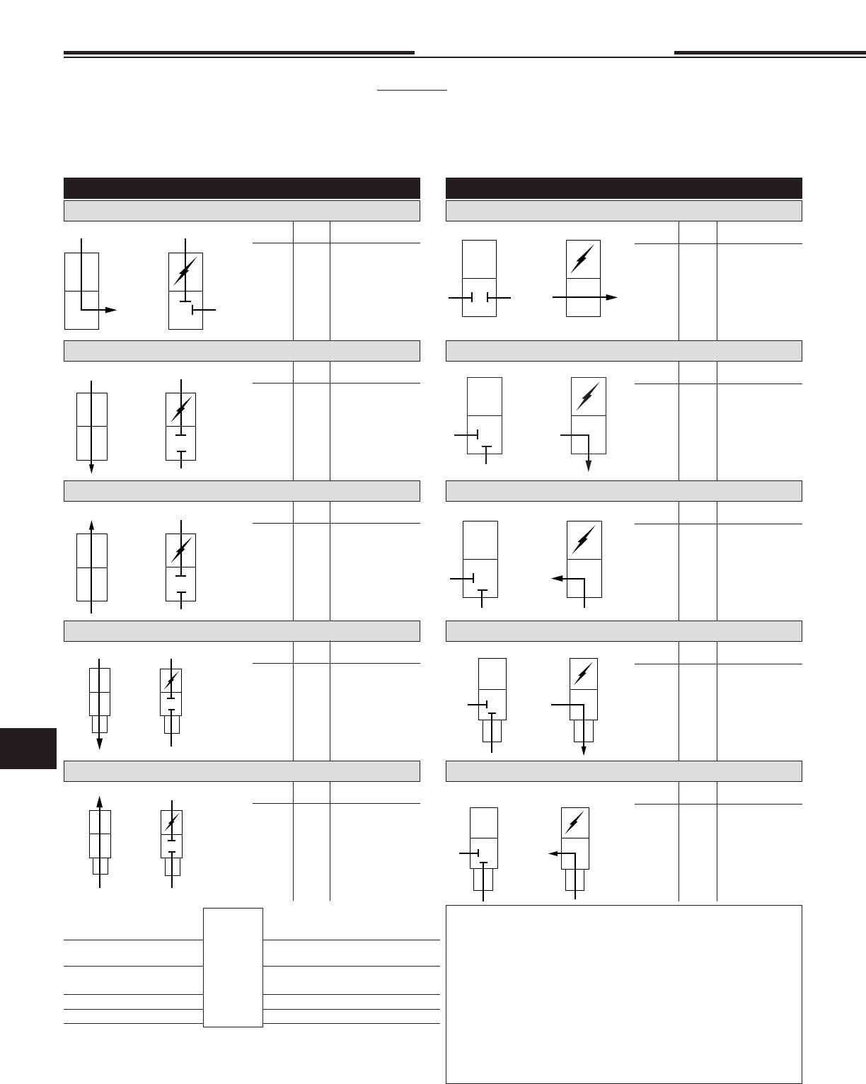
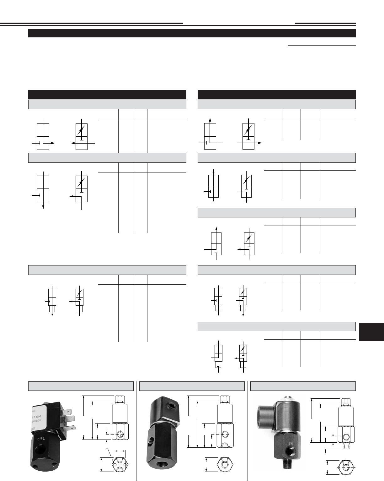
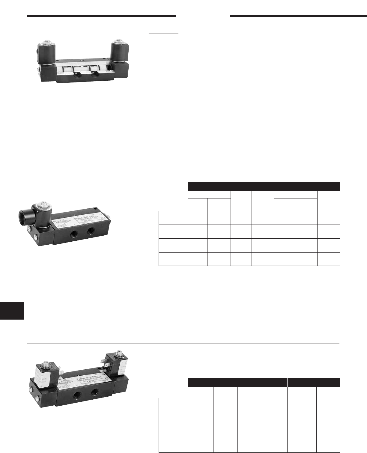
Hex Body 53 STYLE Solenoid Valves
IN OUT Basic Model
10-32 1/8 82-★-✦-NO1
1/8 1/8 82-★-✦-NO2
10-32 1/4 42-★-✦-NO1
1/8 1/4 42-★-✦-NO2
2 WAY NORMALLY OPEN
BODY STYLE 1 SIDE PORT
2 WAY NORMALLY CLOSED
BODY STYLE 1 SIDE PORTS
BODY STYLE 2 FEMALE BOTTOM PORT BODY STYLE 2 FEMALE BOTTOM PORT
BODY STYLE 2 FEMALE BOTTOM PORT BODY STYLE 2 FEMALE BOTTOM PORT
BODY STYLE 3 MALE BOTTOM PORT BODY STYLE 3 MALE BOTTOM PORT
BODY STYLE 3 MALE BOTTOM PORT BODY STYLE 3 MALE BOTTOM PORT
IN OUT Basic Model
1/8 1/8 82-★-✦
1/4 1/4 42-★-✦
IN OUT Basic Model
10-32 1/8 F-82-★-✦-NO1
1/8 1/8 F-82-★-✦-NO2
10-32 1/4 F-42-★-✦-NO1
1/8 1/4 F-42-★-✦-NO2
IN OUT Basic Model
1/8 1/8 F-882-★-✦
1/8 1/4 F-842-★-✦
1/4 1/8 F-482-★-✦
1/4 1/4 F-442-★-✦
IN OUT Basic Model
1/8 10-32 FX-82-★-✦-NO1
1/8 1/8 FX-82-★-✦-NO2
1/4 10-32 FX-42-★-✦-NO1
1/4 1/8 FX-42-★-✦-NO2
IN OUT Basic Model
1/8 1/8 FX-882-★-✦
1/8 1/4 FX-482-★-✦
1/4 1/8 FX-842-★-✦
1/4 1/4 FX-442-★-✦
IN OUT Basic Model
10-32 1/8 082-★-✦-NO1
1/8 1/8 082-★-✦-NO2
10-32 1/4 042-★-✦-NO1
1/8 1/4 042-★-✦-NO2
IN OUT Basic Model
1/8 1/8 882-★-✦
1/8 1/4 842-★-✦
1/4 1/8 482-★-✦
1/4 1/4 442-★-✦
OPTIONS: Specify Suffi x
• 1/8 NPT Adapter
(3 Way N.C. Top Exhaust) .................-A ....... See Pg. 11.6
• Viton Seals (
for media compatibility)
.........-V
• Explosion Proof ............................. -EP ...... See Pg. 11.30
• Pro-Coat™
(Electroless Nickel Plate)
........-N ....... See Pg. 1.10
• Spade Electrical Connections See Pgs. 11.29 &
11.30
ACCESSORIES:
• Solenoid Exhaust Muffl er .............. SM-10 ... See Page 14.1
• Connectors for Mini-DIN “F” .......................... See Pg. 11.30
• Body Hex aluminum, black anodized - 3 Different porting styles.
• Media Air, water & other fl uids compatible with standard Buna-N
seals and aluminum.
• Power See page 11.29
• Operating Temperature:
0°F (–18°C) to +104°F (40°C) ambient.
0°F (–18°C) to +150°F (65°C) media.
• Voltages See page 11.29
• Operating Pressure See chart with orifi ce information
• Internal Parts Stainless Steel
HOW TO ORDER
Insert Letter for Housing at ★
See Chart, Orifi ce Information
EXAMPLE
Basic Model Number X883 See Model Charts
-C C Conduit, G Grommet, F DIN
See Solenoid Information Page 11.29
Number for Orifi ce at ✦ -1
All 3 Way EX Orifi ces are 1/16
Options See Chart, Option Information
Volts & Hertz 120/60 See Solenoid Information Page 11.29
Example: 3 Way N.C., 1/8 NPT Male Bottom Inlet, 1/8 NPT Side Cylin-
der, Conduit Housing, 3/64 Seat, 120 Volts/60 HZ.
Model Number = X883-C-1, 120/60
11.5
In
Out
In
Out
De-Energized Energized
Specifi cations subject to change without notice or incurring obligation
11
Directional Control Valves
IN CYL EX† Basic Model
1/8 1/8 10-32 X-883-★-✦
1/8 1/4 10-32 X-483-★-✦
1/4 1/8 10-32 X-843-★-✦
1/4 1/4 10-32 X-443-★-✦
†
For optional 1/8 NPT Adapter add Suffi x “A”
IN CYL EX† Basic Model
1/8 1/8 10-32 883-★-✦
1/8 1/4 10-32 843-★-✦
1/4 1/8 10-32 483-★-✦
1/4 1/4 10-32 443-★-✦
†
For optional 1/8 NPT Adapter add Suffi x “A”
IN CYL EX† Basic Model
1/8 1/8 10-32 FX-883-★-✦
1/8 1/4 10-32 FX-483-★-✦
1/4 1/8 10-32 FX-843-★-✦
1/4 1/4 10-32 FX-443-★-✦
†
For optional 1/8 NPT Adapter add Suffi x “A”
IN CYL EX Basic Model
10-32 1/8 1/8 883-★-✦-NO1
1/8 1/8 1/8 883-★-✦-NO2
10-32 1/8 1/4 483-★-✦-NO1
1/8 1/8 1/4 483-★-✦-NO2
10-32 1/4 1/8 843-★-✦-NO1
1/8 1/4 1/8 843-★-✦-NO2
10-32 1/4 1/4 443-★-✦-NO1
1/8 1/4 1/4 443-★-✦-NO2
Hex Body
1/8 & 1/4 NPT
2 & 3 Way Valves
2-14-08
3.24
1/8
NPT
Port
2.68
10-32
Port
1.13
.39
.73
1.00 Hex
No. 10-32 x 1/4
Deep Mt'g Thds.
3.67
1/8
NPT
Port
3.11
10-32
Port
1.56
.83
1.00 Hex
3.17
1/8
NPT
Port
2.61
10-32
Port
1.06
.33
1.00 Hex
.50
See Pg. 11.29 for Housing Details See Pg. 11.29 for Housing Details See Pg. 11.29 for Housing Details
In
Cyl
In
Cyl
De-Energized Energized
Ex Ex
In
Cyl
In
Cyl
De-Energized Energized
Ex Ex
In
Cyl
In
Cyl
De-Energized Energized
Ex Ex
In Cyl In Cyl
Ex
De-Energized Energized
Ex
In
Cyl
In
Cyl
De-Energized Energized
Ex Ex
In
Cyl Cyl
In
De-Energized Energized
Ex Ex
In
Cyl
In
Cyl
De-Energized Energized
Ex Ex
In
Cyl
In
Cyl
De-Energized Energized
Ex Ex
ORIFICE INFORMATION
Available Orifi ces and Equivalent Maximum Pressure Ratings for AC Voltages (DC Ratings Slightly Lower)
CFM – Flow @
Cv Factor 2 Way N.O. 2 Way N.C. 3 Way N.O. 3 Way N.C. 100 psi 50 psi
Number 0 1/32 .022 150 psi 500 psi 150 psi 200 psi 1.3 0.9
Number 1 3/64 .055 125 400 125 150 3.5 2.0
Number 2 1/16 .075 100 200 100 100 5.8 3.4
Number 3 3/32 .156 NA 100 NA 60 9.0 6.0
Number 4 1/8 .230 NA 75 NA 30 NA 8.0
All 3 way (EX) exhaust orifi ces are 1/16. All 3 way (EX) exhaust orifi ces are 1/16.
3 WAY NORMALLY OPEN
BODY STYLE 1 SIDE PORT
3 WAY NORMALLY CLOSED
BODY STYLE 1 SIDE PORTS
IN CYL EX† Basic Model
10-32 1/8 1/8 83-★-✦-NO1
1/8 1/8 1/8 83-★-✦-NO2
10-32 1/4 1/4 43-★-✦-NO1
1/8 1/4 1/4 43-★-✦-NO2
BODY STYLE 2 FEMALE BOTTOM PORT BODY STYLE 2 FEMALE BOTTOM PORT
IN CYL EX Basic Model
10-32 1/8 1/8 F-883-★-✦-NO1
1/8 1/8 1/8 F-883-★-✦-NO2
10-32 1/8 1/4 F-483-★-✦-NO1
1/8 1/8 1/4 F-483-★-✦-NO2
10-32 1/4 1/8 F-843-★-✦-NO1
1/8 1/4 1/8 F-843-★-✦-NO2
10-32 1/4 1/4 F-443-★-✦-NO1
1/8 1/4 1/4 F-443-★-✦-NO2
IN CYL EX† Basic Model
1/8 1/8 10-32 F-883-★-✦
1/8 1/4 10-32 F-843-★-✦
1/4 1/8 10-32 F-483-★-✦
1/4 1/4 10-32 F-443-★-✦
BODY STYLE 2 FEMALE BOTTOM PORT
BODY STYLE 3 MALE BOTTOM PORT
BODY STYLE 3 MALE BOTTOM PORT
BODY STYLE 3 MALE BOTTOM PORT
IN CYL EX† Basic Model
1/8 1/8 10-32 83-★-✦
1/4 1/4 10-32 43-★-✦
†
For optional 1/8 NPT Adapter add Suffi x “A”
†
For optional 1/8 NPT Adapter add Suffi x “A”
BODY STYLE 1 – Side Ports BODY STYLE 2 – Female Bottom Port BODY STYLE 3 – Male Bottom Port
11.6
Specifi cations subject to change without notice or incurring obligation
Directional Control Valves
11
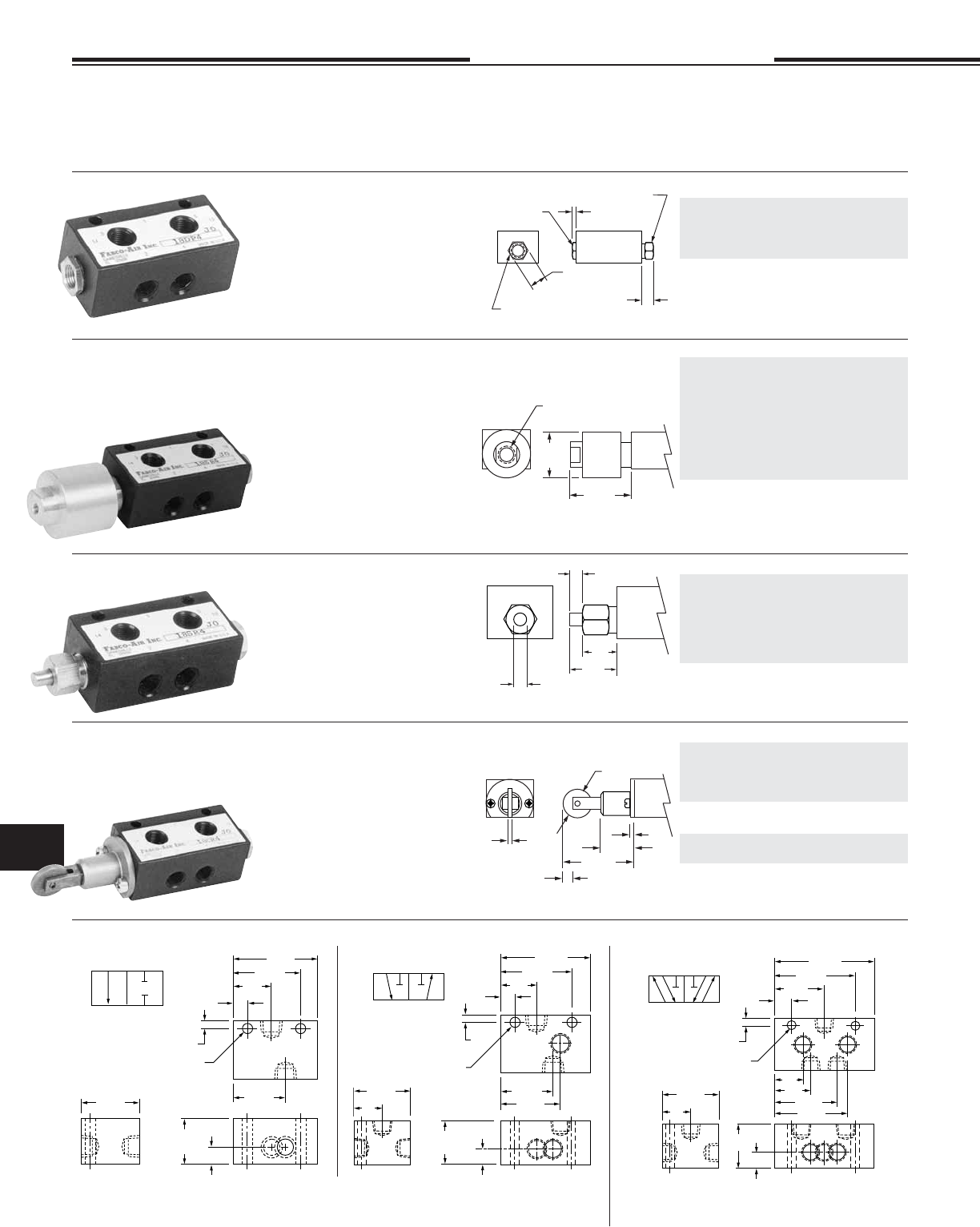
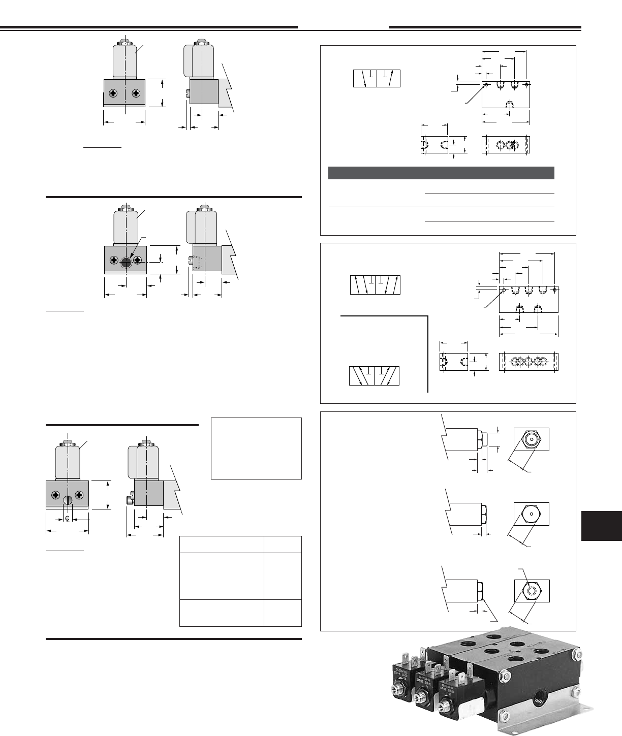
18 Series
1/8 NPT
2, 3 & 4 Way
1-26-08
1/8 NPT Standard.
10-32 = Option -E
Pilot Bushing
Standard or Light Spring
Housing 9/16 Hex
9/16 Hex
.13
.38
1.25
Dia.
1.63
1/8 NPT Standard.
10-32 = Option -E
.25 Dia.
.78
.50
.25 Stroke
.75 Dia.
.13
.1.88
.25 Stroke
.13
.88
Standard 2 Way & 3 Way spring
return are normally closed. For
normally open the actuators may be
exchanged end for end or by speci-
fying -20 for -2 & -30 for -3.
Minimum pilot pressure:
Standard spring . . . . . . . . . 60 psi
Light spring (Option -L) . . . 40 psi
Double pilot . . . . . . . . . . . . 20 psi
2 Way 3 Way 4 Way
Single Pilot - Spring Return
18SP-2 18SP-3 18SP-4
Double pilot
18DP-2 18DP-3 18DP-4
Replacement spool & seals
1800-902 1800-903 1800-904
Light spring, Option -L
10-32 pilot port, Option -E
Air Pilot
Air Pilot Amplifi er
Roller Cam
Rod Actuator
1" Delrin piston in aluminum housing
meets low pressure requirements.
Standard 2 Way & 3 Way spring
return are normally closed. For nor-
mally open the actuators may
be exchanged end for end or by
specifying -20 for -2 & -30 for -3.
Minimum pilot pressure:
Standard spring . . . . . . . . . 10 psi
Light spring (Option -L) . . . . 7 psi
Against 0 psi pilot . . . . . . . . 2 psi
2 Way 3 Way 4 Way
Single Pilot (Amplifi er) - Spring Return
18SA-2 18SA-3 18SA-4
Double pilot - 2 amplifi ers
18DA-2 18DA-3 18DA-4
Double pilot - 1 amplifi er, 1 air pilot
18DAP-2 18DAP-3 18DAP-4
When both pilots are pressurized,
the amplifi er overrides.
Replacement spool & seals
1800-902 1800-903 1800-904
Light spring, Option -L
10-32 pilot port, Option -E
Stainless steel rod in brass bushing.
Standard 2 Way & 3 Way spring
return are normally closed. For
normally open the actuators may be
exchanged end for end or specify by
substituting -20 for -2 & -30 for -3.
Force to actuate:
Standard spring . . . . . . . . . 6.5 lb.
Light spring (Option -L) . . . 5.0 lb.
Double Rod . . . . . . . . . . . . 1.2 lb.
2 Way 3 Way 4 Way
Single Rod - Spring Return
18SR-2 18SR-3 18SR-4
Single Rod- Pilot Return
18SRP-2 18SRP-3 18SRP-4
Double rod
18DR-2 18DR-3 18DR-4
Replacement spool & seals
1800-902 1800-903 1800-904
Light return spring, Option -L
Case hardened steel roller and shaft
in hard anodized aluminum housing.
Standard 2 Way & 3 Way spring return
are normally closed. For normally
open specify by substituting -20 for -2
& -30 for -3.
Force to actuate:
Standard spring . . . . . . . . . 6.5 lb.
Light spring (Option -L) . . . 5.0 lb.
Double Cam . . . . . . . . . . . . 1.2 lb.
2 Way 3 Way 4 Way
Single Cam - Spring Return
18CR-2 18CR-3 18CR-4
Single Cam - Pilot Return
18CRP-2 18CRP-3 18CRP-4
Replacement spool & seals for above
1800-912 1800-913 1800-914
Double cam
18CCR-2 18CCR-3 18CCR-4
Replacement spool & seals
1800-922 1800-923 1800-924
Light return spring, Option -L
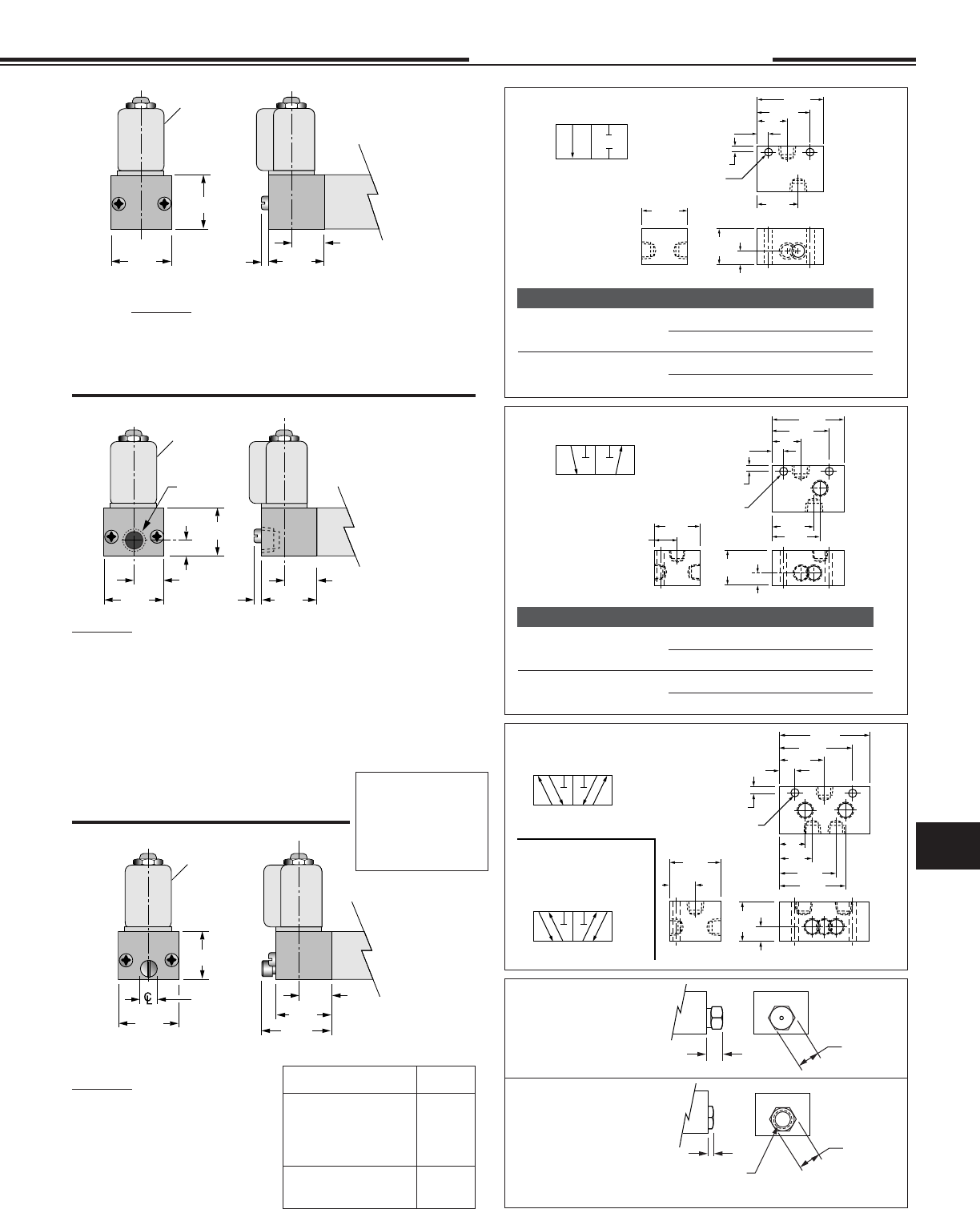
1
2
12 10
12 10
2
1.13
1
.31
.16
.81
1.44
1.81
.20 Dia. Clearance
for #10 Bolt
.38
1.00
1.25
Primary Secondary
2 WAY
31
2
12 10
3 Way
This 3 Way Valve may
be used for any 3 Way,
Selector or Diverter
service.
12 10
2
1.13
1
.44
.16
.81
1.58
2.02
.20 Dia. Clearance
for #10 Bolt
.38
1.00
1.25
Primary Secondary
3
1.34
.63
31
2
14 12
5
4
4 Way - 5 Port ‡
14 12
2
1.52
1
.44
.16
1.20
1.97
2.41
.20 Dia. Clearance
for #10 Bolt
.38
1.25
Primary Secondary
3
1.73
.63
5
4
.89
.67
1.00
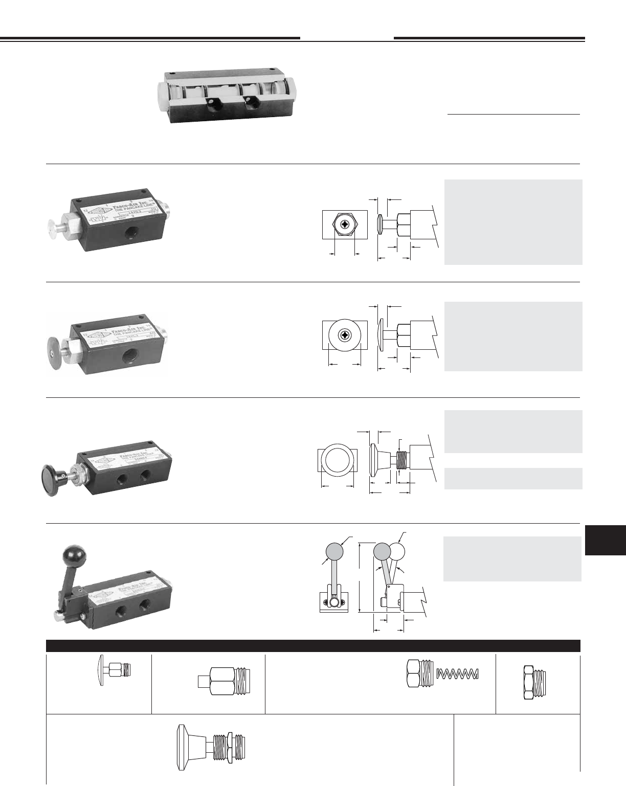
1/8 NPT PORTED, MANUAL, MECHANICAL AND PILOT OPERATED AIR VALVES –
“The Finest in Simplicity”
2, 3 and 4 Way - 2 Position – Operation to 150 psi Air
Suitable for Vacuum directional fl ow applications, but NOT for holding vacuum.
Short stroke of lightweight Delrin® spools provides fast, positive, and reliable response.
Valve Body Dimensions
Note 1: Specify Normally Open by
substituting -20 for -2 & -30 for -3.
Standard 2 & 3 way spring return models are normally closed. Models with thread
in actuators may be converted to normally open by exchanging actuators end for
end. Other models require specifi cation and factory assembly. See note 1.
‡ 4 way - 5 port May be used as either single
inlet - dual exhaust or dual inlet - single exhaust.
11.7
Specifi cations subject to change without notice or incurring obligation
11
Directional Control Valves
• Prelubed with Magnalube®–G Grease
• Interchangeability of Parts
• Cv = 0.27 (14.2 SCFM Free Flow to
Atmosphere at 80 psi Supply)
• Operating temperature +32° to +180°F;
Solenoid controlled models +150°F max.
See pages 11.9 and 11.11.
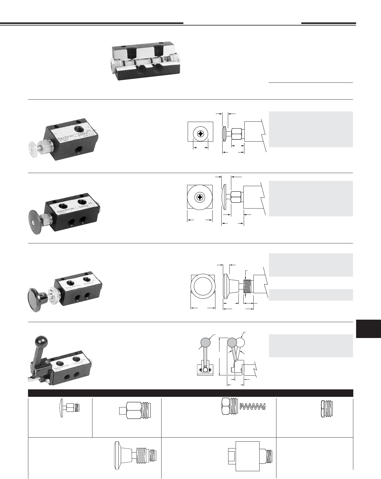
18 Series
1/8 NPT
2, 3 & 4 Way
5-3-12
.75
Dia. .97
.50
.25 Stroke
1.25
Dia. .91
.50
.25 Stroke
1.38
Dia.
.81
1.65
.50
3/4-16
.25 Stroke
(2) 7/8 Hex x .13 thick brass nuts included
1.00
16
°
1.50
Lever
position
when
spring
returned
3.38
.75 Dia.
Palm Button
Assembly
No. 1800-1 Large Button
No. 1800-2 Small Button
Panel Mount Button Assembly
For Detented (with Spool)
No. 1800-7-2 (2W NC) 1800-7-20 (2W NO)
1800-7-3 (3W NC) 1800-7-30 (3W NO)
Above NOT interchangeable End for End
1800-7-4 (4 Way)
For Spring or Pilot Return (No Spool)
1800-8 (2 or 3 Way, NO or NC, and 4 Way))
Rod Actuator
Assembly
No. 1800-3
Spring Housing
Assembly
No. 1800-4 Light Spring only (for Option L).
No. 1800-5 Standard Spring only
No. 1800-46 Light Spring & Housing Ass'y (for Option -L).
No. 1800-56 Standard Spring & Housing Assembly.
MOST THREADED-IN OPERATORS ARE INTERCHANGEABLE BETWEEN ENDS
Pilot Bushing
No. 1800-10 10-32 Port
No. 1800-18 1/8 NPT Port
Un-anodized aluminum button with
stainless steel rod in brass bush-
ing. Standard 2 Way & 3 Way spring
return are normally closed. For
normally open the actuators may be
exchanged end for end or specify by
substituting -20 for -2 & -30 for -3.
Force to actuate:
Standard spring . . . . . . . . . 6.5 lb.
Light spring (Option -L) . . . 5.0 lb.
Double Button . . . . . . . . . . 1.2 lb.
2 Way 3 Way 4 Way
Single Button - Spring Return
18PS-2 18PS-3 18PS-4
Single Button - Pilot Return
18PSP-2 18PSP-3 18PSP-4
Double Button
18PPS-2 18PPS-3 18PPS-4
Replacement spool & seals
1800-902 1800-903 1800-904
Light spring Option -L
Small Palm Button
Large Palm Button
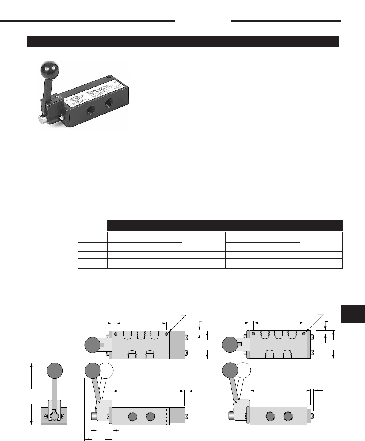
Hand Lever
Panel Mount Button
Red anodized aluminum button with
stainless steel rod in brass bush-
ing. Standard 2 Way & 3 Way spring
return are normally closed. For
normally open the actuators may be
exchanged end for end or specify by
substituting -20 for -2 & -30 for -3.
Force to actuate:
Standard spring . . . . . . . . . 6.5 lb.
Light spring (Option -L) . . . 5.0 lb.
Double Button . . . . . . . . . . 1.2 lb.
Phenolic button with plated steel rod
in brass bushing; black button stan-
dard, red button Option -R. Standard
2 Way and 3 Way assemblies are
normally closed with knob in the “out”
position. For normally open specify by
substituting -20 for -2 and -30 for -3.
Force to actuate:
Standard spring . . . . . . . . . 6.5 lb.
Light spring (Option -L) . . . 5.0 lb.
Double Button . . . . . . . . . . 1.2 lb.
Detented . . . . . . . . . . . . . . 3.0 lb.
Air Pilot Amplifi er
1/8 NPT Standard
No. 18 AMP-1 1/8 NPT Port
No. 10 AMP-1 10-32 Port Option -E
Fabco-Air has the expertise
and willingness to design.
modify and adapt these valves
to your necessary and specifi c
job requirements. Please ad-
vise us of your needs.
Hardened & plated steel shaft with
unique connection to spool results
in positive shifting. Standard 2 Way
& 3 Way spring return are normally
closed. For normally open specify by
substituting -20 for -2 & -30 for -3.
Force to actuate:
Standard spring . . . . . . . . . 4.0 lb.
Light spring (Option -L) . . . 3.0 lb.
Detented . . . . . . . . . . . . . . 2.0 lb.
• Aluminum bar body
• Anodized black
• Honed & burnished bore
• Pressure balanced spool
• Delrin spool
• Buna-N seals
• Operation to 150 psi
• 4 Way - 5 port may be used as either
single inlet - dual exhaust or dual inlet - single exhaust.
2 Way 3 Way 4 Way
Single Button - Spring Return
18PL-2 18PL-3 18PL-4
Single Button - Pilot Return
18PLP-2 18PLP-3 18PLP-4
Double Button
18PPL-2 18PPL-3 18PPL-4
Replacement spool & seals
1800-902 1800-903 1800-904
Light spring Option -L
2 Way 3 Way 4 Way
Spring Return
18PMS-2 18PMS-3 18PMS-4
Pilot Return
18PMP-2 18PMP-3 18PMP-4
Replacement spool & seals for above.
1800-902 1800-903 1800-904
Detented (Push Pull)
18PMD-2 18PMD-3 18PMD-4
Replacement spool & seals
1800-942† 1800-943† 1800-944†
Light spring Option -L
2 Way 3 Way 4 Way
Spring Return
18HLS-2 18HLS-3 18HLS-4
Detented
18HL-2 18HL-3 18HL-4
Replacement spool & seals
1800-932† 1800-933† 1800-934†
† Includes factory assembled
spool attachments.
Light spring Option -L
FEATURES OPTIONS
• Light spring – Specify Option -L
• #10-32 Pilot Port – Specify Option -E
• Viton seals – Specify Option -V
• Spools for bleeder pilot
• Multiple stacking with or without
common inlet. Consult factory.
Note 1: Specify Normally Open by
substituting -20 for -2 & -30 for -3.
11.8
OPERATING TEMPERATURE FOOTNOTE SEE PAGE 11.1
Specifi cations subject to change without notice or incurring obligation
Directional Control Valves
11
18 Series
1/8 NPT
2, 3 & 4 Way
2-14-08
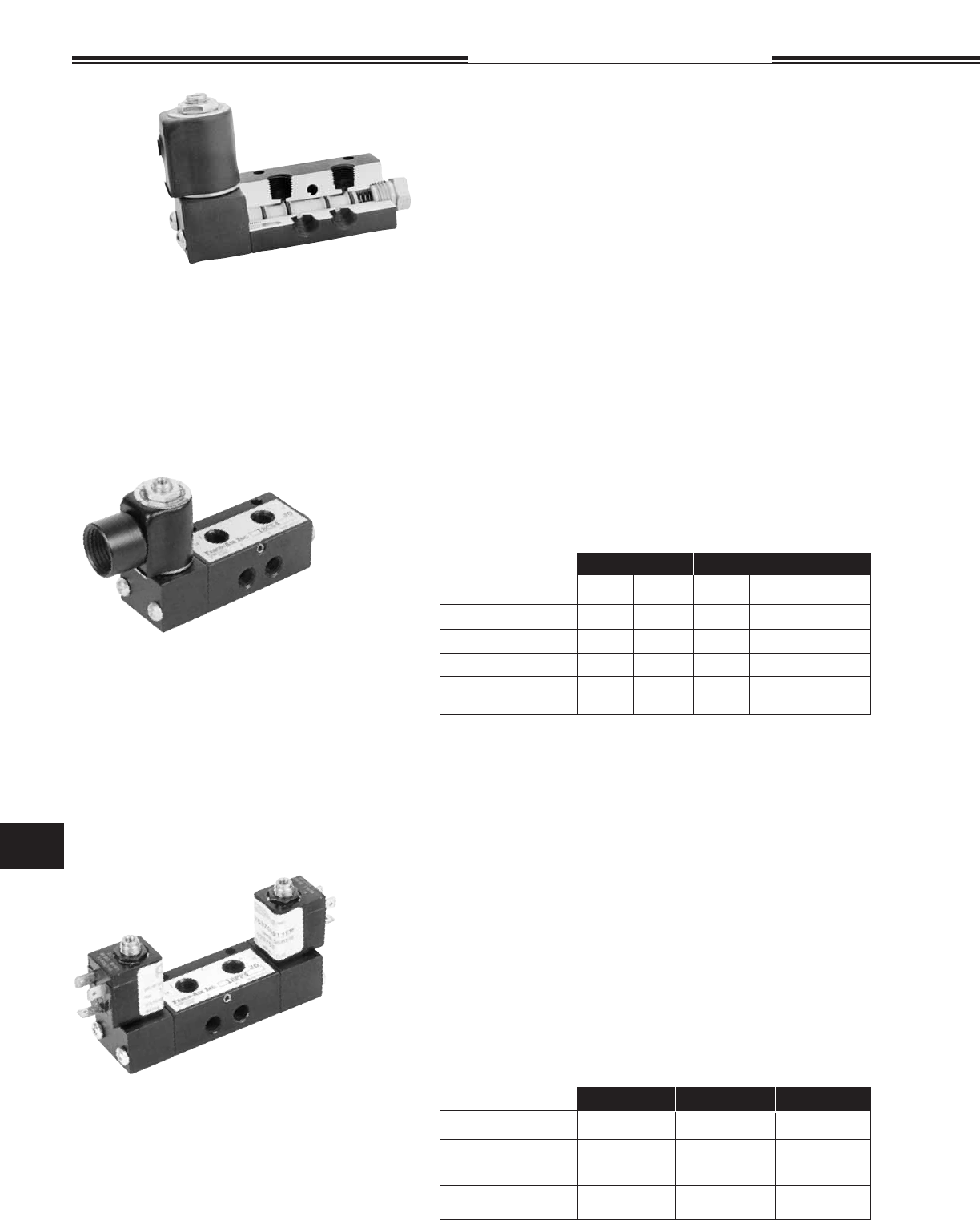
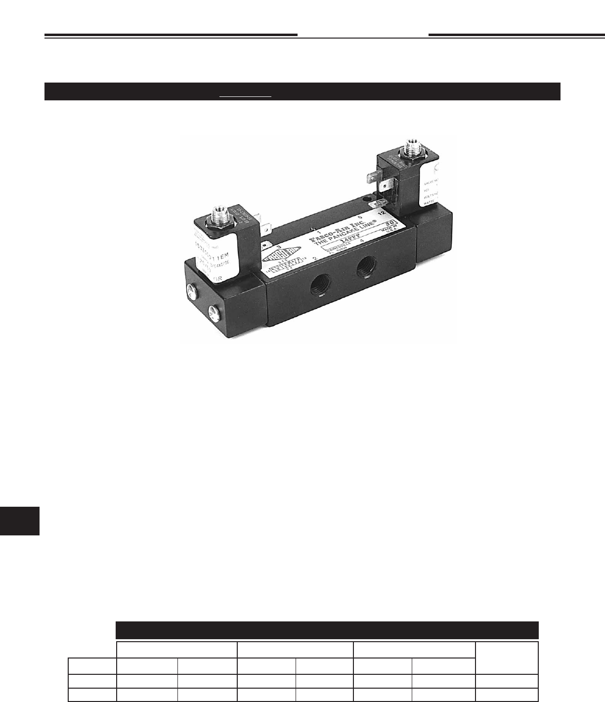
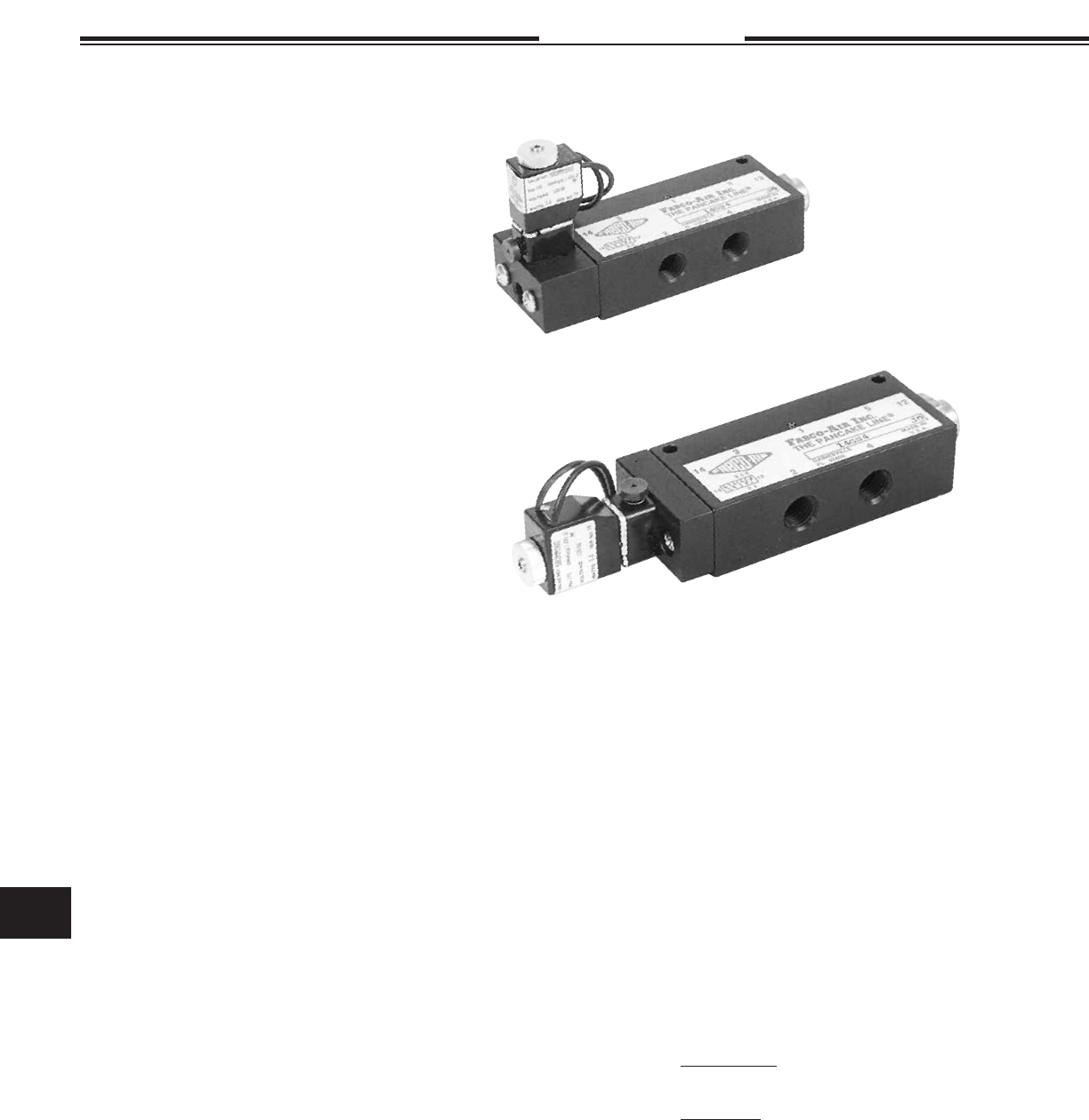
1/8 NPT Ported 53 STYLE Solenoid Controlled, Pilot Operated Air Valves
2, 3 & 4 Way - 2 Position – Operation to 150 psi Air
Features
• Black anodized aluminum bar stock body • Honed and burnished bore
• Lightweight Delrin® spool provides fast, positive, reliable response
• Buna N seals • Operation to 150 psi
• Coils & housing information see page 11.29
• Cv = 0.27 • 14.2 SCFM free fl ow to atmosphere @ 80 psi
• Prelubed with Magnalube® -G grease
• Operating temperature:
+32°F (0°C) to +104°F (40°C) ambient.
+32°F (0°C) to +150°F (65°C) media.
Standard catalog models are suitable for operation in intermittent low tem-
peratures in a range of 0° to + 32 °F.
A custom aluminum spool may be substituted when long-term applica-
tion temperatures are expected to be 0° to +32°F. These should be limited
to double solenoid actuation. Consider that actuation force may exceed
catalog specs and that spring return models may not be reliable at these
low temperatures. Please consult factory.
Options
Manual Override
Locking . . . . . . . . . . . . . . . . . . . -MO1
Non-Locking . . . . . . . . . . . . . . . -MO4
External Pilot . . . . . . . . . . . . . . . . . . . . . -X
Light Spring . . . . . . . . . . . . . . . . . . . . . . -L
Viton Seals for media compatibility. . . . . -V
Explosion Proof Operators . . . . . . . . . .-EP
See page 11.30
Dual Inlet - Single Exhaust 4 Way
See page 11.10
Note 1: Optional Flow Path
Operating Range
Internal Pilot Supply (Standard)
Standard Spring . . . . . . . . 60 to 150 psi
Light Spring, Option -L . . . 40 to 150 psi
Pilot Return (0 psi Pilot) . . 20 to 150 psi
External Pilot Supply, Option -X
Inlet Pressure . . . . . . . . . . 0 to 150 psi
External Pilot Supply, Option -X
Standard Spring . . . . . . . . 60 to 150 psi
Light Spring, Option -L . . . 40 to 150 psi
Pilot Return (0 psi Pilot) . . 20 to 150 psi
Operating Range
Internal Pilot Supply (Standard)
Inlet . . . . . . . . . . . . . . . . . . 20 to 150 psi
External Pilot Supply, Option -X
Inlet Pressure . . . . . . . . . . . 0 to 150 psi
Pilot Supply . . . . . . . . . . . . 20 to 150 psi
2 WAY 3WAY 4 WAY
Normally Normally Normally Normally
Closed Open Closed Open
Conduit Housing 18CS-2 18CS-20 18CS-3 18CS-30 18CS-4
Grommet Housing 18GS-2 18GS-20 18GS-3 18GS-30 18GS-4
Male Mini-DIN Housing 18FS-2 18FS-20 18FS-3 18FS-30 18FS-4
Replacement
Spool and Seals 1800-912 1800-9120 1800-913 1800-9130 1800-914
2 WAY 3WAY 4 WAY
Conduit Housing 18CC-2 18CC-3 18CC-4
Grommet Housing 18GG-2 18GG-3 18GG-4
Male Mini-DIN Housing 18FF-2 18FF-3 18FF-4
Replacement 1800-922 1800-923 1800-924
Spool and Seals
SINGLE SOLENOID - PILOT RETURN MODELS
A pilot return can be substituted for the standard spring return.
It may be used in two manners.
1. For a pulse signal, then pilot return.
2. As a constant, adjustable force, spring.
Supply pilot port with a constant regulated pressure. This will act
as a very constant spring against the solenoid controlled pilot
signal. The pilot return should be a minimum of 20 psi below the
solenoid controlled pressure.
To Specify, Substitute P for S in the Model Number.
(Example 18CP-3-120/60)
1/8 NPT Pilot Port standard.
10-32 Pilot Port optional, Specify Option -E.
SINGLE SOLENOID
To Order Specify: Model Number from chart
Options
Volts & Hertz (See page 11.29)
DOUBLE SOLENOID
To Order Specify: Model Number from chart
Options
Volts & Hertz (See page 11.29)
11.9
Specifi cations subject to change without notice or incurring obligation
11
Directional Control Valves 18 Series
1/8 NPT
2, 3 & 4 Way
11-8-04
1.25 1.00
.50
1.34
1.00
See Housing
Details
Page 11.29
.31 Dia.
1.25 1.00
.50
.14 Max.
1.00
.31
1/8 NPT
See Housing
Details
Page 11.29
.63
1.25 1.00
.50
.14 Max.
1.00
See Housing
Details
Page 11.29
1
2
12 10
12 10
2
1.13
1
.31
.16
.81
1.44
1.81
.20 Dia. Clearance
for #10 Bolt
.38
1.00
1.25
Primary Secondary
2 WAY
31
2
12 10
3 Way
12 10
2
1.13
1
.44
.16
.81
1.58
2.02
.20 Dia. Clearance for #10 Bolt
.38
1.00
1.25
Primary Secondary
3
1.34
.63
31
2
14 12
5
4
31
2
14 12
5
4
4 Way - Standard:
Single Inlet - Port #1 - Dual Exhaust
14 12
2
1.52
1
.44
.16
1.20
1.97
2.41
.20 Dia. Clearance for #10 Bolt
1.25
3
1.73
.63
5
4
.38
Primary Secondary
.89
.67
1.00
Note 1: Optional Flow Path:
Dual Inlet - Ports #3 & #5 -
Single Exhaust. Use External
Pilot Supply (Option -X).
.13
Pilot Port
9/16 Hex
9/16 Hex
.38
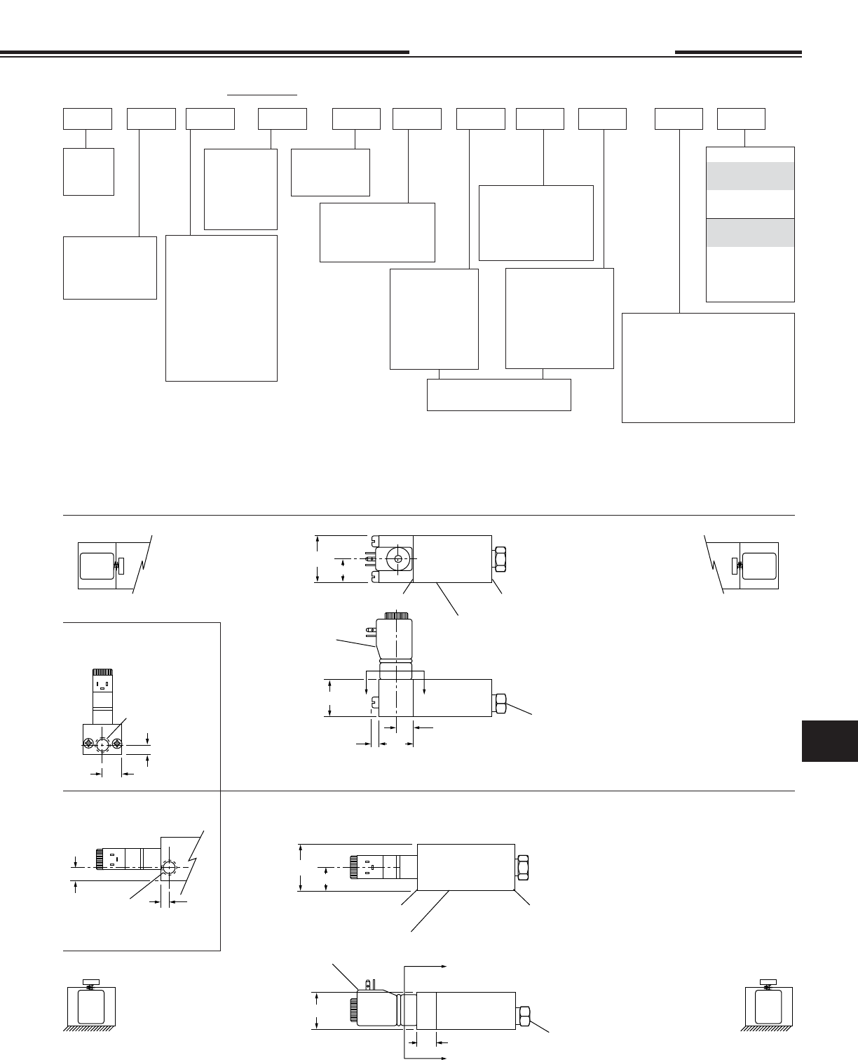
Standard 53 STYLE Solenoid Operator
The solenoid operator is a 3-way NC valve which, upon receiving an
electrical signal, directs a pilot pressure to shift the main valve spool.
As standard, the operator is internally supplied with air pressure from
the main valve inlet. Also see “External Pilot Supply” below.
53 STYLE Solenoid Operator with External Pilot Supply
Option -X
In the following listed applications, as well as many others, a proper
air supply may not be available from the main valve inlet. For these ap-
plications, an external pilot supply port is available (Option -X).
A proper air supply to this port then supplies the solenoid with air
pressure for piloting the main valve spool.
• Dual Inlet - Single Exhaust 4 Way.
• Insuffi cient pressure at main valve inlet.
• Media, at main valve inlet, other than air.
• Extremely fast cycling.
53 STYLE Solenoid Operator
with Manual Override
This manual override is a 3-way
NC valve that when pushed,
directs pilot pressure to shift the
main spool. Pressure must be
present at main valve inlet for this
override to function.
Spring Return Valves End Operator
10 Spring
12 Solenoid
10 Solenoid
12 Spring
Normally Closed
Normally Open
Spring Return Valves End Operator
10 Spring
12 Solenoid
10 Solenoid
12 Spring
Normally Closed
Normally Open
Spring Return:
Standard and Optional Light
Pilot Return: -P
See Page 11.7
1/8 NPT Port Standard – 10-32 Port Specify Option -E
TYPE SUFFIX
LOCKING
Push to override; -MO1
Turn to lock in;
Turn back to release.
NON-LOCKING
Push to override. -MO4
Option -X is NOT
combinable with
either Option -MO1
or -MO4
11.10
Specifi cations subject to change without notice or incurring obligation
Directional Control Valves
11
18 Series
1/8 NPT
2, 3 & 4 Way
2-14-08
Features
• Black anodized aluminum bar stock body
• Honed and burnished bore
• Lightweight Delrin® spool provides fast, positive, reliable response
• Simplicity • Reliability
• Corrosion resistant construction
• Buna N seals • Operation to 150 psi
• Solenoid operator information see page 11.31
• Cv = 0.27 • 14.2 SCFM Free fl ow to atmosphere @ 80 psi
• Prelubed with Magnalube® -G grease
• Operating temperature:
+32°F (0°C) to +122°F (50°C) ambient.
+32°F (0°C) to +122°F (50°C) media.
Standard catalog models are suitable for operation in intermittent low
temperatures in a range of 0° to + 32 °F.
A custom aluminum spool may be substituted when long-term application
temperatures are expected to be 0° to +32°F. These should be limited
to double solenoid actuation. Consider that actuation force may exceed
catalog specs and that spring return models may not be reliable at these
low temperatures. Please consult factory.
Operating Ranges, psi
#1 Solenoid #4 Solenoid
0.9 Watts 3.5 Watts
Internal Pilot Supply (Standard) Inlet Pressure
Non Spring Return . . . . . . . . . . . . . . . . . . 20 to 130 .........20 to 145
Spring Return. . . . . . . . . . . . . . . . . . . . . . 60 to 130 .........60 to 145
Light Spring Option -L . . . . . . . . . . . . . . . 40 to 130 .........40 to 145
External Pilot Supply, Option -X Inlet Pressure . . . 0 to 150 ...........0 to 150
External Pilot Supply, Option -X Pilot Supply
Non Spring Return . . . . . . . . . . . . . . . . . . 20 to 130 .........20 to 145
Spring Return. . . . . . . . . . . . . . . . . . . . . . 60 to 130 .........60 to 145
Light Spring Option -L . . . . . . . . . . . . . . . 40 to 130 .........40 to 145
1/8 NPT Ported 58 STYLE Solenoid Controlled, Pilot Operated Air Valves
2, 3 & 4 Way - 2 Position – Operation to 150 psi Air
Options
External Pilot . . . . . . . . . . . . . . . . . . . .-X
† External Pilot and Viton Seals . . . . -XV
Light Spring . . . . . . . . . . . . . . . . . . . . .-L
† Viton Seals are available in the main
valve only, for media compatibility, and
therefore only in conjunction with External
Pilot +32°F (0°C) to +122°F (50°C).
11.11
Specifi cations subject to change without notice or incurring obligation
11
Directional Control Valves 18 Series
1/8 NPT
2, 3 & 4 Way
1-26-08
31
4
2
Primary Solenoid
Manual Override
Position
Section A – A
1
3
Primary Solenoid
Manual Override
Position
Section B – B
3
1
4
2
Secondary Solenoid
Manual Override
Position
Section A – A
1
3
Secondary Solenoid
Manual Override
Position
Section B – B
Primary Actuator End
1.25
.63
Spring Return
Shown
.50
1.00
.14 Max.
1.00
See page 11.31
for Operator Details
2, 3, or 4 Way
Valve Body
Secondary Actuator End
See page 11.10
for Body Details
AASide View
B
B
1.25
.63
See page 11.31
for Operator Details
See page 11.10
for Body Details
Primary Actuator End Secondary Actuator End
Spring Return
Shown
Side View
1.00
.50
2, 3, or 4 Way
Valve Body
External Pilot
Supply
Option -X
1/8 NPT
.31
.63
.38
.28
1/8 NPT
External Pilot Supply
Option -X
Upright
Solenoid Attitude #1
(Solenoid centerline 90°
to Valve Body centerline)
58 STYLE Solenoid Valve, Model Number Code
Series
18
1/8 NPT
Primary Actuator
F = Micro DIN
G = Wire leads
See page 11.31
18 FS4 411 0 120/60———
Function
2 = 2 Way
3 = 3 Way
4 = 4 Way
See page
11.7 Primary Solenoid
Attitude
1 = Upright 90° to Body
5 = Inline with Body
Primary Solenoid
Manual Override
0 = None
1 = Position #1
2 = Position #2‡
3 = Position #3
4 = Position #4‡
Secondary Solenoid
Attitude
0 = Other than Solenoid
1 = Upright 90° to Body
5 = Inline with Body
Volts / Hertz
#1 Solenoid
(0.9 Watts)
12 VDC
24 VDC
#4 Solenoid
(3.5 Watts)
24/60 VAC
120/60 VAC
12 VDC
24 VDC
Example: 18FS-4-41100-120/60
1/8 NPT – Primary Actuator Solenoid with Micro DIN coil; Secondary Actuator, Spring Return – 4 Way Function
3.5 Watt Solenoid; Primary Solenoid Upright position with Manual Override in Position #1; Secondary Actuator is
not a Solenoid; no Manual Override on Secondary Actuator – No Options – 120 Volt/60 Hertz.
Solenoid Watts
1 = 0.9 Watts
4 = 3.5 Watts
Secondary Solenoid
Manual Override
0 = None
1 = Position #1
2 = Position #2‡
3 = Position #3
4 = Position #4‡
0
Secondary Actuator
F = Micro DIN*
G = Wire leads*
S = Spring**
P = Pilot**
R = Rod**
B = Small Button**
L = Large Button**
* See page 11.31
** See pages 11.7 &
11.8 for details
Options
-X = External Pilot
-XV = † External Pilot & Viton Seals
-L = Light Spring
†
Viton Seals are available in the main
valve only for media compatability and
therefore only in conjunction with
External Pilot (+32° to 180°F).
‡ Solenoid Attitude #1 ONLY
#1 = Upright 90° to Body
Inline
Solenoid Attitude #5
(Solenoid centerline inline
with Valve Body centerline)
11.12
Specifi cations subject to change without notice or incurring obligation
Directional Control Valves
11
5-3-12
14, M14 & 34 Series
1/4 & 3/8 NPT
2, 3 & 4 Way
1/8 NPT
Pilot Bushing
.38
7/8
Hex
Note: See Stacking (Pressure Manifolded)
informnation below
.31
Dia. .91
.50
.38 Stroke
Note: See Stacking (Pressure Manifolded)
informnation below
.38
.75 Dia.
.2.38
.38 Stroke
.13 1.25
Note: See Stacking (Pressure Manifolded)
informnation below
Brass bushing with 1/8 NPT port.
Standard 3 Way spring return is nor-
mally closed. For normally open the
actuators may be exchanged end for
end or by specifying -30 for -3.
Minimum pilot pressure:
Standard spring . . . . . . . . . 50 psi
Light spring (Option -L) . . . 40 psi
Double pilot . . . . . . . . . . . . 20 psi
3 Way 4 Way
Single Pilot - Spring Return
1/4 NPT 14SP-3 14SP-4
1/4 Stacking N/A M14SP-4
3/8 NPT 34SP-3 34SP-4
Double Pilot
1/4 NPT 14DP-3 14DP-4
1/4 Stacking N/A M14DP-4
3/8 NPT 34DP-3 34DP-4
Replacement spool & seals
1400-903 1400-904
Stainless steel rod in brass bushing.
Standard 3 Way spring return is
normally closed. For normally open
the actuators may be exchanged
end for end or specify by substituting
-30 for -3.
Force to actuate:
Standard spring . . . . . . . . 10.5 lb.
Light spring (Option-L) . . . 9.0 lb.
Double rod . . . . . . . . . . . . . 1.2 lb.
3 Way 4 Way
Single Rod - Spring Return
1/4 NPT 14SR-3 14SR-4
1/4 Stacking N/A M14SR-4
3/8 NPT 34SR-3 34SR-4
Single Rod - Pilot Return
1/4 NPT 14SRP-3 14SRP-4
1/4 Stacking N/A M14SRP-4
3/8 NPT 34SRP-3 34SRP-4
Double Rod
1/4 NPT 14DR-3 14DR-4
1/4 Stacking N/A M14DR-4
3/8 NPT 34DR-3 34DR-4
Replacement spool & seals
1400-903 1400-904
Case hardened steel roller and shaft
in hard anodized aluminum hous-
ing. Standard 3 Way spring return is
normally closed. For normally open
specify by substituting -30 for -3.
Force to actuate:
Standard spring . . . . . . . . 10.5 lb.
Light spring (Option-L) . . . 9.0 lb.
Cam-Pilot return . . . . . . . . 1.2 lb.
3 Way 4 Way
Single Cam - Spring Return
1/4 NPT 14CR-3 14CR-4
1/4 Stacking N/A M14CR-4
3/8 NPT 34CR-3 34CR-4
Single Cam - Pilot Return
1/4 NPT 14CRP-3 14CRP-4
1/4 Stacking N/A M14CRP-4
3/8 NPT 34CRP-3 34CRP-4
Replacement spool & seals for above
1400-913 1400-914
Double cam
1/4 NPT 14CCR-3 14CCR-4
1/4 Stacking N/A M14CCR-4
3/8 NPT 34CCR-3 34CCR-4
Replacement spool & seals
1400-923 1400-924
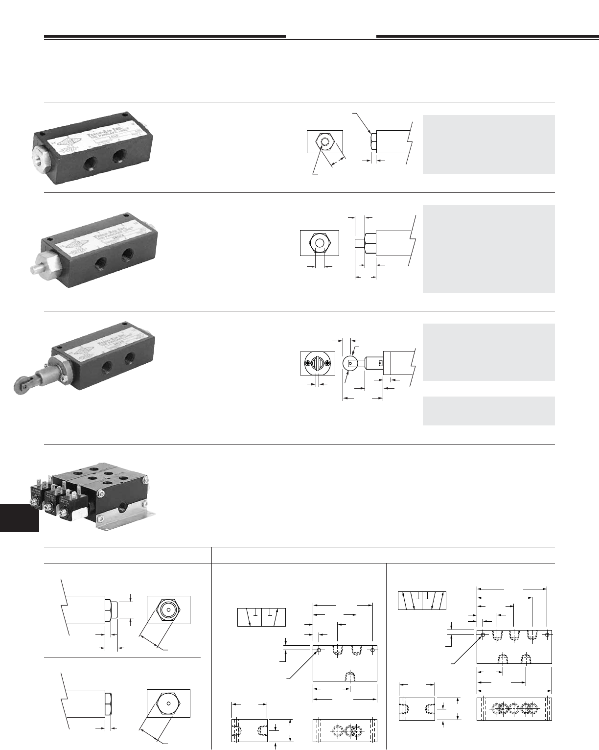
Air Pilot
Roller Cam
Rod Actuator
Stacking - Pressure Manifold
7/8 Hex
.25
.50
.69 Dia.
STANDARD SPRING
7/8 Hex
.25
LIGHT SPRING OPTION -L
31
2
12 10
2 Way / 3 Way
This 3 Way Valve may be used for any 2 Way,
3 Way, Selector or Diverter service.
12
10
2
1.78
1
1.19
2.09
2.88
.20 Dia. Clearance
for #10 Bolt
.56 1.13
1.75
Primary Secondary
3
3.13
.19
.25
315
24
1214
4 Way - 5 Port ‡
14 12
2
2.53
1
1.94
2.84
3.63
.20 Dia. Clearance
for #10 Bolt
.56
1.34
1.75
Primary Secondary
5
3.88
.19
.25
1.03
4
1.13
‡ 4 Way - 5 Port May be used as either Single Inlet -
Dual Exhaust or Dual Inlet Single Exhaust
3
Selected models of the 14 Series 1/4" air valves can be stacked and
pressure manifolded for space and money savings. The valve bod-
ies are bolted together with 4 through tie bolts and the pressure is
manifolded with O-Ring seals between the valves. Inlet pressure can
be connected to either or both ends of the stack. Due to the fact that
the pressure port, on all valve bodies, is tapped on both sides, the
pressure manifold can be plugged at any point within the stack. This
allows you to supply the stack with two different pressures, one from
each end.
See Model Numbers in the Air-Pilot
Rod Actuator, Roller Cam and Small
Palm Button sections of Pgs 11.13
and 11.14 and Solenoid Valves on
Pgs 11.19 and 11.20.
To Order: Specify the Quantity of
each model desired, the Order in
which they are to be assembled, and
Brackets, if desired.
Spring Cap Dimensions Valve Body Dimensions
1/4 & 3/8 NPT PORTED, MANUAL, MECHANICAL AND PILOT OPERATED AIR VALVES –
“The Finest in Simplicity”
2, 3 and 4 Way - 2 Position – Operation to 150 psi Air
Suitable for Vacuum directional fl ow applications, but NOT for holding vacuum.
The short stroke of the lightweight Delrin® spool provides fast, posiitive, and reliable response.
Note 1: Specify Normally Open by
substituting -30 for -3.
11.13
Specifi cations subject to change without notice or incurring obligation
11
Directional Control Valves
Pilot Bushing
No. 1400-18 1/8 NPT Port
2-7-08
14, M14 & 34 Series
1/4 & 3/8 NPT
2, 3 & 4 Way
.75
Dia. 1.09
.50
.38 Stroke
1.25
Dia. 1.03
.50
.38 Stroke
1.38
Dia.
.81
1.81
.50
3/4-16
.38 Stroke
(2) 7/8 Hex x .13 thick brass nuts included
1.00
25
°
1.75
Lever
position
when
spring
returned.
3.50
1.00 Dia.
• Prelubed with Magnalube®–G Grease
• Interchangeability of Parts
• Cv = 1.0
56.2 SCFM Free Flow to
Atmosphere at 80 psi Supply
• Operating Temperature +32° to +180°F;
Solenoid controlled models +150°F max.
See pages 11.17, 11.19 & 11.21.
• Aluminum bar body
• Anodized black
• Honed & burnished bore
• Pressure balanced spool
• Delrin spool
• Buna-N seals
• Operation to 150 psi
• 4 Way - 5 port may be used as either
single inlet - dual exhaust or dual inlet - single exhaust.
FEATURES OPTIONS
• Light spring – Specify Option -L
• Viton seals – Specify Option -V
• Spools for bleeder pilot –
Consult factory.
Un-anodized aluminum button with
stainless steel rod in brass bush-
ing. Standard 3 Way spring return is
normally closed. For normally open
the actuators may be exchanged
end for end or specify by substituting
-30 for -3.
Force to actuate:
Standard spring ............... 10.5 lb.
Light spring (Option -L) ..... 9.0 lb.
Double Button .................... 1.2 lb.
3 Way 4 Way
Single Button - Spring Return
1/4 NPT 14PS-3 14PS-4
1/4 Stacking N/A M14PS-4
3/8 NPT 34PS-3 34PS-4
Single Button - Pilot Return
1/4 NPT 14PSP-3 14PSP-4
1/4 Stacking N/A M14PSP-4
3/8 NPT 34PSP-3 34PSP-4
Double Button
1/4 NPT 14PPS-3 14PPS-4
1/4 Stacking N/A M14PPS-4
3/8 NPT 34PPS-3 34PPS-4
Replacement spool & seals
1400-903 1400-904
Red anodized aluminum button with
stainless steel rod in brass bush-
ing. Standard 3 Way spring return is
normally closed. For normally open
the actuators may be exchanged
end for end or specify by substituting
-30 for -3.
Force to actuate:
Standard spring ............... 10.5 lb.
Light spring (Option -L) ..... 9.0 lb.
Double Button .................... 1.2 lb.
Phenolic button with plated steel
rod in brass bushing; black button
standard, red button Option -R.
Standard 3 Way assemblies are
normally closed with knob in the
“out” position. For normally open
specify by substituting -30 for -3.
Force to actuate:
Standard spring .............. 10.5 lb.
Light spring (Option -L)..... 9.0 lb.
Detented ........................... 3.0 lb.
Hardened & plated steel shaft with
unique connection to spool results
in positive shifting. Standard 3 Way
spring return is normally closed. For
normally open specify by substituting
-30 for -3.
Force to actuate:
Standard spring . . . 10.0 lb.
Light spring . . . . . . 6.0 lb.
(Option -L)
Detented . . . . . . . . . 3.0 lb.
3 Way 4 Way
Single Button - Spring Return
1/4 NPT 14PL-3 14PL-4
3/8 NPT 34PL-3 34PL-4
Single Button - Pilot Return
1/4 NPT 14PLP-3 14PLP-4
3/8 NPT 34PLP-3 34PLP-4
Double Button
1/4 NPT 14PPL-3 14PPL-4
3/8 NPT 34PPL-3 34PPL-4
Replacement spool & seals
1400-903 1400-904
3 Way 4 Way
Spring Return
1/4 NPT 14HLS-3 14HLS-4
3/8 NPT 34HLS-3 34HLS-4
Detented
1/4 NPT 14HL-3 14HL-4
3/8 NPT 34HL-3 34HL-4
Replacement spool & seals
1400-933† 1400-934†
† Includes factory assembled
spool attachments
Palm Button
Assembly
No. 1400-1 Large Button
No. 1400-2 Small Button
Panel Mount Button Assembly
Black button standard
Red button Option -R
Rod Actuator
Assembly
No. 1400-3
Spring Housing
Assembly
No. 1400-4 Light Spring only (for Option -L)
No. 1400-5 Standard Spring only
No. 1400-46 Light Spring & Housing Assembly (for Option -L).
No. 1400-56 Standard Spring & Housing Assembly .
MOST THREADED-IN OPERATORS ARE INTERCHANGEABLE BETWEEN ENDS
Fabco-Air has the expertise
and willingness to design.
modify and adapt these valves
to your necessary and specifi c
job requirements. Please advise
us of your needs.
For Detented (with Spool)
No. 1400-7-3 (3 Way Normally Closed)
1400-7-30 (3 Way Normally Open)
Above NOT interchangeable End for End
1400-7-4 (4 Way)
For Spring or Pilot Return (No Spool)
1400-8 (3 Way N.O. or N.C., and 4 Way)
Small Palm Button
Large Palm Button
Hand Lever
Panel Mount Button 3 Way 4 Way
Spring Return
1/4 NPT 14PMS-3 14PMS-4
3/8 NPT 34PMS-3 34PMS-4
Pilot Return
1/4 NPT 14PMP-3 14PMP-4
3/8 NPT 34PMP-3 34PMP-4
Replacement spool & seals for above
1400-903 1400-904
Detented (Push Pull)
1/4 NPT 14PMD-3 14PMD-4
3/8 NPT 34PMD-3 34PMD-4
Replacement spool & seals
1400-943† 1400-944†
† Includes factory assembled spool attach-
ments.
Note 1: Specify Normally Open by
substituting -30 for -3.
11.14
OPERATING TEMPERATURE FOOTNOTE SEE PAGE 11.1
Specifi cations subject to change without notice or incurring obligation
Directional Control Valves
11
14 & 34 Series
1/4 & 3/8 NPT
4-Way, 3 Position
315
24
1214
315
24
1214
4-Way - 5 Ported - 3 Position - Type F
“Float”
Center position - Inlet blocked and
Cylinders open to exhaust
Used to vent both ends of cylinder to allow
cylinder to fl oat with a manual or machine move-
ment. Flow controls or exhaust speed controls
should not be used.
4-Way - 5 Ported - 3 Position - Type B
“Blocked”
Center position - All ports blocked and
isolated. Use on conventional block and
hold circuits.
New Spools for
14 & 34 Series
Air Valves
1/4 NPT & 3/8 NPT Ported, Pilot Operated Air Valves
5 Ported, 3-Position 4-Way Operation
Features
• Aluminum bar body
• Anodized black
• Honed and burnished bore
• Delrin spool, pressure balanced
• Buna N seals
• May be used as either
single inlet-dual exhaust or
dual inlet-single exhaust
• Pre-lubed with Magnalube–G® Grease
Operating Range
• Operating pressure...............0 to 150 psi
• Minimum pilot pressure ........50 psi
• Cv = 1.0 (56.2 SCFM free fl ow to
atmosphere @ 80 psi supply)
• Temperature .........................+32° to 180°F
For long-term, continuous operation in a range
of +150°F to +180°F, the Viton seal option can
provide the benefi ts of reliable leak-free opera-
tion and extended durability.
Options
Viton Seals, Specify Option –V
1/4 NPT & 3/8 NPT Ported, Manual & Pilot Operated, & Solenoid Controlled Air Valves
New 5 Ported, 3-Position 4-Way Operation
Valve Dimensions
5-15-12
Model 14-DPF Shown
Model Number Guide: 3-Position, Pilot Operated
Spring Centered Spool Replacement
Spool Type 1/4 NPT Ports 3/8 NPT Ports Spool and Seals
B Spool 14 DPB 34DPB 1400-904B
F Spool 14DPF 34DPF 1400-904F
11.15
.20 Clearance for #10 bolt
1/8 NPT
Pilot Port
2 Places
1.00
Both Ends
1.13
.19 Typ.
4.88
.25 3.38
1.75
.19
Specifi cations subject to change without notice or incurring obligation
11
Directional Control Valves 14 & 34 Series
1/4 & 3/8 NPT
4-Way, 3 Position
Operating Range
• Operating pressure........ 0 to 150 psi
• Cv = 1.0 (56.2 SCFM free fl ow to
atmosphere @ 80 psi supply)
• Temperature ...............+32° to 180°F
Standard catalog models are suitable for operation in
intermittent low temperatures in a range of 0° to + 32 °F.
A custom aluminum spool may be substituted when long-
term application temperatures are expected to be –40°to
+32°F. These should be limited to manual actuation, not
spring centered. Consider that actuation force may exceed
catalog specs and that spring return models may not be
reliable at these low temperatures. Please consult factory.
For long-term, continuous operation in a range of +150°F
to +180°F, the Viton seal option can provide the benefi ts
of reliable leak-free operation and extended durability.
Options
Viton Seals, Specify Option –V
1/4 NPT & 3/8 NPT Ported, Hand Lever Operated Air Valves
5 Ported, 3-Position 4-Way Operation
Dimensions – Spring Centered Spool Dimensions – Detented Spool
2-7-08
Model 14-HLF Shown
Spring Centered Spool Replacement Detented Spool Replacement
Spool Type 1/4 NPT Ports 3/8 NPT Ports 1/4 NPT Ports 3/8 NPT Ports
B Spool 14HLSB 34HLSB 1400-934SB 14HLB 34HLB 1400-934B
F Spool 14HLSF 34HLSF 1400-934SF 14HLF 34HLF 1400-934F
Model Number Guide: 3-Position, Hand Lever Operated
Spool & Seals Spool & Seals
11.16
.20 Clearance for #10 bolt
3.38
.25
1.75
.19
4.88
1.75
1.00
3.94
.19
.20 Clearance for #10 bolt
3.38
.25
1.75
.19
4.00 .19
Features
Hardened and plated steel shaft
with unique connections results
in positive shifting
• Aluminum bar body
• Anodized black
• Honed and burnished bore
• Delrin spool, pressure balanced
• Buna N seals
• May be used as either
single inlet-dual exhaust or
dual inlet-single exhaust
• Pre-lubed with Magnalube–G® Grease
Specifi cations subject to change without notice or incurring obligation
Directional Control Valves
11
14 & 34 Series
1/4 & 3/8 NPT
4-Way, 3 Position
Features
• Aluminum bar body
• Anodized black
• Honed and burnished bore
• Delrin spool
• Buna N seals
• Cv = 1.0 (56.2 SCFM free fl ow to
atmosphere @ 80 psi supply)
• Operation to 150 psi
• Operating Temperature:
+32°F (0°C) to +104°F (40°C) ambient.
+32°F (0°C) to +150°F (65°C) media.
• Pre-lubed with Magnalube–G® Grease
• Coils & Housing information see page 11.29.
Operating Range
Internal pilot supply - standard
Inlet .............................50 to 150 psi
External pilot supply Option –X
Inlet .............................0 to 150 psi
Pilot Supply ................50 to 150 psi
Ordering
Choose valve model number from table
below and add option suffi xes as required
and specify voltage/hertz.
Model 14-FFB Shown
1/4 NPT & 3/8 NPT Ported, 53 Style Solenoid Controlled, Pilot Operated Air Valves
5 Ported, 3-Position 4-Way Operation
1-26-08
Conduit Housing “C” Grommet Housing “G” Male Mini-DIN Housing “F” Replacement
Spool Type 1/4 NPT Ports 3/8 NPT Ports 1/4 NPT Ports 3/8 NPT Ports 1/4 NPT Ports 3/8 NPT Ports
B Spool 14-CCB 34-CCB 14-GGB 34-GGB 14-FFB 34-FFB 1400-904B
F Spool 14-CCF 34-CCF 14-GGF 34-GGF 14-FFF 34-FFF 1400-904F
Model Number Guide: 4-Way, 3-Position, Spring Centered Double Solenoid Valves
Spool & Seals
11.17
Specifi cations subject to change without notice or incurring obligation
11
Directional Control Valves 14 & 34 Series
1/4 & 3/8 NPT
4-Way, 3 Position
.20 Clearance for #10 bolt
.25 3.38
1.75
.19
3.88
6.38
1.13
2.65
1.50
.63
1.03
1.25
1/2 NPT
10-32 Exhaust Port
Housing can rotate 360
°
1.03
10-32 Exhaust Port
1.50
.75
.63
Housing can rotate 360
°
Conduit Housing "C"
Grommet Housing "G"
Male Mini-DIN Housing "F"
53 Style Solenoid Operators
Standard 53 Style Operator
The solenoid operator is a 3-way NC valve
which, upon receiving an electrical signal,
directs pressure to shift the main valve spool.
As standard, the operator is internally supplied
with air pressure from the main valve inlet.
53 Style Operator with External Pilot
Option –X
In the following listed applications, as well as
many others, a proper air supply may not be
available from the main valve inlet. For these
applications, an external pilot supply port is
available (Option –X). A proper air supply to
this port then supplies the solenoid with air
pressure for piloting the main valve spool.
• Dual inlet, single exhaust
• Insuffi cient Pressure at main valve inlet
• Media at main valve inlet is other than air
• Extreme fast cycling
Valve Dimensions
8-26-04
1.75 1.25
.75
.14 Max.
1.13
.44
1/8 NPT
11.18
1.58
.44
.88
10-32
Exhaust
Port
.43
.22
(11 mm)
spacing
.47
.37
.57 1.50
Line Terminals
.25 x .03
Ground Terminal
.25 x .03
Housing can rotate 360
°
Specifi cations subject to change without notice or incurring obligation
Directional Control Valves
11
11.19 2-14-08
14, M14 & 34 Series
1/4 & 3/8 NPT
2, 3 & 4 Way
1/4 & 3/8 NPT Ported 53 STYLE Solenoid Controlled, Pilot Operated Air Valves
2, 3 & 4 Way - 2 Position – Operation to 150 psi Air
Options
Manual override
Locking . . . . . . . . . . . . . . . . . . . -MO1
Non-Locking . . . . . . . . . . . . . . . -MO4
External pilot. . . . . . . . . . . . . . . . . . . . . -X
Light spring. . . . . . . . . . . . . . . . . . . . . . .-L
Viton seals for media compatibility . . . . -V
Explosion proof operators. . . . . . . . . . -EP
See page 11.30
Dual Inlet - Single Exhaust 4 Way
See page 11.20, Note 1: Optional Flow Path.
Operating Range
Internal Pilot Supply (Standard)
Standard Spring . . . . . . . . 50 to 150 psi
Light Spring, Option -L . . . 40 to 150 psi
Pilot Return (0 psi Pilot) . . 30 to 150 psi
External Pilot Supply, Option -X
Inlet Pressure . . . . . . . . . . 0 to 150 psi
External Pilot Supply, Option -X
Standard Spring . . . . . . . . 50 to 150 psi
Light Spring, Option -L . . . 40 to 150 psi
Pilot Return (0 psi Pilot) . . 30 to 150 psi
Operating Range
Internal Pilot Supply (Standard)
Inlet . . . . . . . . . . . . . . . . . . 30 to 150 psi
External Pilot Supply, Option -X
Inlet Pressure . . . . . . . . . . . 0 to 150 psi
Pilot Supply . . . . . . . . . . . . 30 to 150 psi
SINGLE SOLENOID - PILOT RETURN MODELS
A pilot return can be substituted for the standard spring return.
It may be used in two manners.
1. For a pulse signal, then pilot return.
2. As a constant, adjustable force, spring.
Supply pilot port with a constant regulated pressure. This will act
as a very constant spring against the solenoid controlled pilot signal.
The pilot return should be a minimum of 30 psi below the solenoid
controlled pressure.
To Specify, Substitute P for S in the Model Number. (Ex: 14CP-3-120/60)
SINGLE SOLENOID
DOUBLE SOLENOID
‡2 / 3 WAY 4 WAY 4 WAY Stacking ‡2 / 3 WAY 4 WAY
Conduit
Housing 14CC-3 14CC-4 M14CC-4 34CC-3 34CC-4
Grommet
Housing 14GG-3 14GG-4 M14GG-4 34GG-3 34GG-4
Male Mini-DIN
Housing 14FF-3 14FF-4 M14FF-4 34FF-3 34FF-4
Replacement
Spool & Seals 1400-923 1400-924 1400-904 1400-923 1400-924
1/4 NPT PORTS 3/8 NPT PORTS
See pg 11.20
‡2 / 3 WAY 4 WAY 4 WAY ‡2 / 3WAY 4 WAY
Normally Normally Stacking Normally Normally
Closed Open See pg 11.20 Closed Open
Conduit
Housing 14CS-3 14CS-30 14CS-4 M14CS-4 34CS-3 34CS-30 34CS-4
Grommet
Housing 14GS-3 14GS-30 14GS-4 M14GS-4 34GS-3 34GS-30 34GS-4
Male Mini-DIN
Housing 14FS-3 14FS-30 14FS-4 M14FS-4 34FS-3 34FS-30 34FS-4
Replacement
Spool & Seals 1400-913 1400-9130 1400-914 1400-904 1400-913 1400-9130 1400-914
1/4 NPT PORTS 3/8 NPT PORTS
‡Plug 3-Way Valve
for 2-Way Service.
‡Plug 3-Way Valve
for 2-Way Service.
Features
• Black anodized aluminum bar stock body • Honed and burnished bore
• Lightweight Delrin® spool provides fast, positive, reliable response
• Buna N seals • Operation to 150 psi
• Coils & housing information see page 11.29
• Cv = 1.0 • 56.2 SCFM free fl ow to atmosphere @ 80 psi
• Prelubed with Magnalube® -G grease
• Operating temperature:
+32°F (0°C) to +104°F (40°C) ambient.
+32°F (0°C) to +150°F (65°C) media.
Standard catalog models are suitable for operation in intermittent low tem-
peratures in a range of 0° to + 32 °F.
A custom aluminum spool may be substituted when long-term applica-
tion temperatures are expected to be 0° to +32°F. These should be limited
to double solenoid actuation. Consider that actuation force may exceed
catalog specs and that spring return models may not be reliable at these
low temperatures. Please consult factory.
To Order Specify: Model Number from chart
Options
Volts & Hertz (See page 11.29)
To Order Specify: Model Number from chart
Options
Volts & Hertz (See page 11.29)
Specifi cations subject to change without notice or incurring obligation
11
Directional Control Valves
11-8-04
14, M14 & 34 Series
1/4 & 3/8 NPT
2, 3 & 4 Way
1.75 1.00
.50
.14 Max.
1.13
.44
1/8 NPT
.88
See Housing
Details
Page 11.29
1.75 1.00
.50
1.13
1.34
.31 Dia.
See Housing
Details
Page 11.29
31
2
12 10
3 Way
This 3 Way Valve may
be used for any 2 Way,
3 Way, Selector or
Diverter service.
12
10
2
1.78
1
1.19
2.09
2.88
.20 Dia. Clearance
for #10 Screw
.56 1.13
1.75
Primary Secondary
3
3.13
.19
.25
2 Way Function
315
24
1214
4 Way - 5 Port
Standard: Single Inlet - Port #1 - Dual Exhaust.
14 12
2
2.53
1
1.94
2.84
3.63
.20 Dia. Clearance
for #10 Bolt
.56
1.34
1.75
Primary Secondary
3
3.88
.19
.25
1.03
4
1.13
5
31
2
14 12
5
4
Note 1: Optional Flow Path:
Dual Inlet - Ports #3 & #5 -
Single Exhaust. Use External
Pilot Supply (Option -X).
Standard 53 STYLE Solenoid Operator
The solenoid operator is a 3-way NC valve which, upon receiving an
electrical signal, directs a pilot pressure to shift the main valve spool.
As standard, the operator is internally supplied with air pressure from
the main valve inlet. Also see “External Pilot Supply” below.
53 STYLE Solenoid Operator with External Pilot Supply
Option -X
In the following listed applications, as well as many others, a proper
air supply may not be available from the main valve inlet. For these ap-
plications, an external pilot supply port is available (Option -X).
A proper air supply to this port then supplies the solenoid with air
pressure for piloting the main valve spool.
• Dual Inlet - Single Exhaust 4 Way.
• Insuffi cient pressure at main valve inlet.
• Media, at main valve inlet, other than air.
• Extremely fast cycling.
53 STYLE Solenoid Operator
with Manual Override
This manual override is a 3-way
NC valve that when pushed,
directs pilot pressure to shift the
main spool. Pressure must be
present at main valve inlet for this
override to function.
TYPE SUFFIX
LOCKING
Push to override; -MO1
Turn to lock in;
Turn back to release.
NON-LOCKING
Push to override. -MO4
STACKING - PRESSURE MANIFOLDED
Versions of these 1400 Series 1/4 NPT solenoid valves with different adaptor blocks
can be stacked and pressure manifolded for space and money savings. The valve
bodies are bolted together with 4 through tie bolts and the pressure is manifolded
with O-Ring seals between valves. Inlet pressure can be connected to either or both
ends of the stack. Due to the fact that the pressure port, on all valve bodies, is tapped
on both sides, the pressure manifold can be plugged at any point within the stack.
This allows you to supply the stack with two different pressures, one from each end.
Versions of the Air Pilot, Rod Actuator, Roller Cam and Small Palm Button valves
may be mounted in the same stack along with these solenoid valves.
7/8 Hex
.25
.50
.69 Dia.
Standard Spring Return
7/8 Hex
.25
Light Spring Return
Option -L
.25
Pilot Return
Option -P
1/8 NPT Port
See Page 11.13 Pilot Bushing
1/8 NPT
7/8 Hex
Spring Return Valves End Operator
10 Spring
12 Solenoid
10 Solenoid
12 Spring
Normally Closed
Normally Open
TO ORDER
Specify the quantity of each model
desired, the order in which they are to
be assembled, and Brackets, if desired.
11.20
Option -X
is NOT combinable
with either Option
-MO1 or -MO4
1.75 1.00
.50
.14 Max.
1.13
See Housing
Details
Page 11.29
Specifi cations subject to change without notice or incurring obligation
Directional Control Valves
11
11.21
14 & 34 Series
1/4 & 3/8 NPT
2, 3 & 4-Way
2-14-08
Operating Ranges, psi
#1 Solenoid #4 Solenoid
0.9 Watts 3.5 Watts
Internal pilot supply (standard) inlet pressure
Non Spring Return . . . . . . . . . . . . . . . . . . 30 to 130 .........30 to 145
Spring Return. . . . . . . . . . . . . . . . . . . . . . 50 to 130 .........50 to 145
Light Spring Option -L . . . . . . . . . . . . . . . 40 to 130 .........40 to 145
External pilot supply, Option -X inlet pressure . . . . 0 to 150 ...........0 to 150
External pilot supply, Option -X pilot supply
Non Spring Return . . . . . . . . . . . . . . . . . . 30 to 130 .........30 to 145
Spring Return. . . . . . . . . . . . . . . . . . . . . . 50 to 130 .........50 to 145
Light Spring Option -L . . . . . . . . . . . . . . . 40 to 130 .........40 to 145
1/4 & 3/8 NPT Ported 58 STYLE Solenoid Controlled, Pilot Operated Air Valves
2, 3 & 4 Way - 2 Position
Options
External Pilot . . . . . . . . . . . . . . . . . . . .-X
† External Pilot and Viton Seals . . . . -XV
Light Spring . . . . . . . . . . . . . . . . . . . . .-L
† Viton Seals are available in the main
valve only, for media compatibility, and
therefore only in conjunction with External
Pilot: +32°F (0°C) to +122°F (50°C).
Features
• Black anodized aluminum bar stock body
• Honed and burnished bore
• Lightweight Delrin® spool provides fast, positive, reliable response
• Simplicity • Reliability
• Corrosion resistant construction
• Buna N seals • Operation to 150 psi
• Solenoid operator information see page 11.31
• Cv = 1.0
• 56.2 SCFM Free fl ow to atmosphere @ 80 psi
• Prelubed with Magnalube® -G grease
• Operating temperature:
+32°F (0°C) to +122°F (50°C) ambient.
+32°F (0°C) to +122°F (50°C) media.
Standard catalog models are suitable for operation in intermittent low tempera-
tures in a range of 0° to + 32 °F.
A custom aluminum spool may be substituted when long-term application
temperatures are expected to be 0° to +32°F. These should be limited to double
solenoid actuation. Consider that actuation force may exceed catalog specs
and that spring return models may not be reliable at these low temperatures.
Please consult factory.
Specifi cations subject to change without notice or incurring obligation
11
Directional Control Valves
11.22
14 & 34 Series
1/4 & 3/8 NPT
2, 3 & 4-Way
1-19-08
31
4
2
Primary Solenoid
Manual Override
Position
Section A – A
1
3
Primary Solenoid
Manual Override
Position
Section B – B
3
1
4
2
Secondary Solenoid
Manual Override
Position
Section A – A
1
3
Secondary Solenoid
Manual Override
Position
Section B – B
Primary Actuator End
1.75
.88
Spring Return
Shown
.50
1.00
See page 11.31
for Operator Details
Secondary Actuator End
B
B
.13
See page 11.20
for Body Details
3 or 4 Way
Valve Body
.50
Side View
Primary Actuator End
1.75
.88
Spring Return
Shown
.50
1.00
.14 Max.
1.00
See page 11.31
for Operator Details
3 or 4 Way
Valve Body
Secondary Actuator End
AASide View
.13
See page 11.20
for Body Details
External Pilot
Supply
Option -X
1/8 NPT
.44
.88
.63
.28
1/8 NPT
External Pilot Supply
Option -X
58 STYLE Solenoid Valve, Model Number Code
Series
14 = 1/4 NPT
34 = 3/8 NPT
Primary Actuator
F = Micro DIN
G = Wire leads
See page 11.31
14 FS4 411 0 120/60———
Function
3 = 3 Way
4 = 4 Way
See page
11.13
For 2 Way service
plug a 3 Way Valve
Primary Solenoid
Attitude
1 = Upright 90° to Body
5 = Inline with Body
Primary Solenoid
Manual Override
0 = None
1 = Position #1
2 = Position #2‡
3 = Position #3
4 = Position #4‡
Secondary Solenoid
Attitude
0 = Other than Solenoid
1 = Upright 90° to Body
5 = Inline with Body
Example: 14FS-4-41100-120/60
1/4 NPT – Primary Actuator Solenoid with Micro DIN coil; Secondary Actuator, Spring Return – 4 Way Function
3.5 Watt Solenoid; Primary Solenoid Upright position with Manual Override in Position #1; Secondary Actuator is
not a Solenoid; no Manual Override on Secondary Actuator – No Options – 120 Volt/60 Hertz.
Solenoid Watts
1 = 0.9 Watts
4 = 3.5 Watts
Secondary Solenoid
Manual Override
0 = None
1 = Position #1
2 = Position #2‡
3 = Position #3
4 = Position #4‡
0
Secondary Actuator
F = Micro DIN*
G = Wire leads*
S = Spring**
P = Pilot**
R = Rod**
B = Small Button**
L = Large Button**
* See page 11.31
** See pages 11.13 &
11.14 for details
Options
-X = External Pilot
-XV = † External Pilot & Viton Seals
-L = Light Spring
†
Viton Seals are available in the main
valve only for media compatability and
therefore only in conjunction with
External Pilot (+32° to 180°F).
‡ Solenoid Attitude #1 ONLY
#1 = Upright 90° to Body
Upright
Solenoid Attitude #1
(Solenoid centerline 90°
to Valve Body centerline)
Inline
Solenoid Attitude #5
(Solenoid centerline inline
with Valve Body centerline)
Volts / Hertz
#1 Solenoid
(0.9 Watts)
12 VDC
24 VDC
#4 Solenoid
(3.5 Watts)
24/60 VAC
120/60 VAC
12 VDC
24 VDC
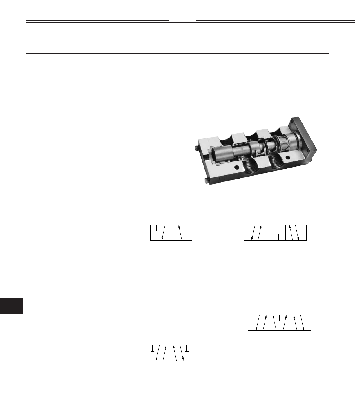
Specifi cations subject to change without notice or incurring obligation
Directional Control Valves
11
11.23
Specials
Fabco-Air, Inc. has the expertise and willing-
ness to design and modify these valves to
your necessary and specifi c job require-
ments. Please advise us of your needs. See
pages
ii & iii
8-26-04
12, 12A, 12B & 38 Series
3/8 & 1/2
NPT
315
24
12 14
315
24
12 14
4-Way - 5 Ported - 3 Position - Type F
“Float”
Center position - Inlet blocked and
Cylinders open to exhaust.
Used to vent both ends of cylinder to allow
cylinder to fl oat with a manual or machine
movement. Flow controls or exhaust speed
controls should not be used.
4-Way - 5 Ported - 3 Position - Type B
“Blocked”
Center position - All ports blocked and
isolated. Use on conventional block and
hold circuits.
315
24
12 14
31
2
12 10
2-Way or 3 Way - 2 Position - Type 3
This 3 Way Valve may be used for any 2 Way,
3 Way, Selector or Diverter service.
When used with internally supplied Solenoid
Operators, the Supply Pressure must be con-
nected to Port #1. For this same reason when
a normally open Solenoid Valve is ordered the
Solenoid Operator will be mounted on end 10
and the Spring on End 12.
4-Way - 5 Ported - 2 Position - Type 2
Use on all 4 Way - 2 Position applications
Note: Any of these 4 Way Valves, except the internally supplied Solenoid Valves, (See
Option -X) can be used as Dual Inlet, Single Exhaust. Using this concept, with different
pressures for force application and retraction, can effect large savings of high pressure
air and its cost. The larger the cylinder or the faster the cycle, the higher the savings.
Catalog Options
• Manual Overrides for Piloted and
Solenoid Valves
• External Pilot Supply for Solenoid
Valve Option -X
• Explosion Proof Operators, Spade
Coil Connections, and other Solenoid
Coil choices - see Pg 11.29 - 11.32
• High Flow Body (see Model Charts)
• Service Kits
2 or 3 Way - Seal Kit 12PV-903
4 Way - Seal Kit 12PV-904
• Dual Inlet - Single Exhaust - 4 Way:
See note below
• Muffl ers for Solenoid Exhaust…
SM-10, See page 14.4
• Other Operator Combinations
Solenoid - Pilot Return
Solenoid - Push-Pull Knob
See Model Charts
Custom Options
• 10-32 Pilot Ports
• 10-32 Auxiliary Pressure Outlets
• Viton Seals
• Stacking and Manifolding to
Customer requirements
Spools
Features
• Direct ported 3/8 NPT, 1/2 NPT
and 1/2 NPT high fl ow:
2 & 3 Way - 2 Position.
4 Way - 2 & 3 Position.
• Aluminum bar stock body and
operator blocks, black anodized.
• Light weight aluminum spool,
hard anodized for long life.
• Operator blocks fi eld
interchangeable.
• Buna N seals.
• Operating temperature (0° to + 180°F);
solenoid controlled models +150° F max.
See pages 11.25 & 11.26.
• All spool seals size checked to
assure reliability.
• Single Subbase or multiple manifolds
with 3/8 and 1/2 NPT ports for
4 Way - 2 & 3 Position see Pg 11.27.
• High fl ow factors, see Pg 11.27.
• Parts anodized for corrosion resistance.
• Aluminum end caps, anodized red,
locate counterbores in body to
control static squeeze on seals.
• Aluminum center cages, anodized
gold, have lips to hold seals in place.
• Spool cushioned with Delrin®-Urethane
bumper combination that absorbs
shock but does not bounce the spool.
• Simple construction for easy servicing.
• Spool “Lands” double tapered and
polished to assure easy entry into seal.
• Prelubed with Magnalube® -G grease.
38 SERIES: 3/8 NPT Ported Air Valves
12, 12A & 12B SERIES: 1/2 NPT Ported Air Valves
2, 3 & 4 Way; 2 & 3 Position Operation to 150 psi
Note! Spring return & spring centered models NOT
suitable for dry air service.
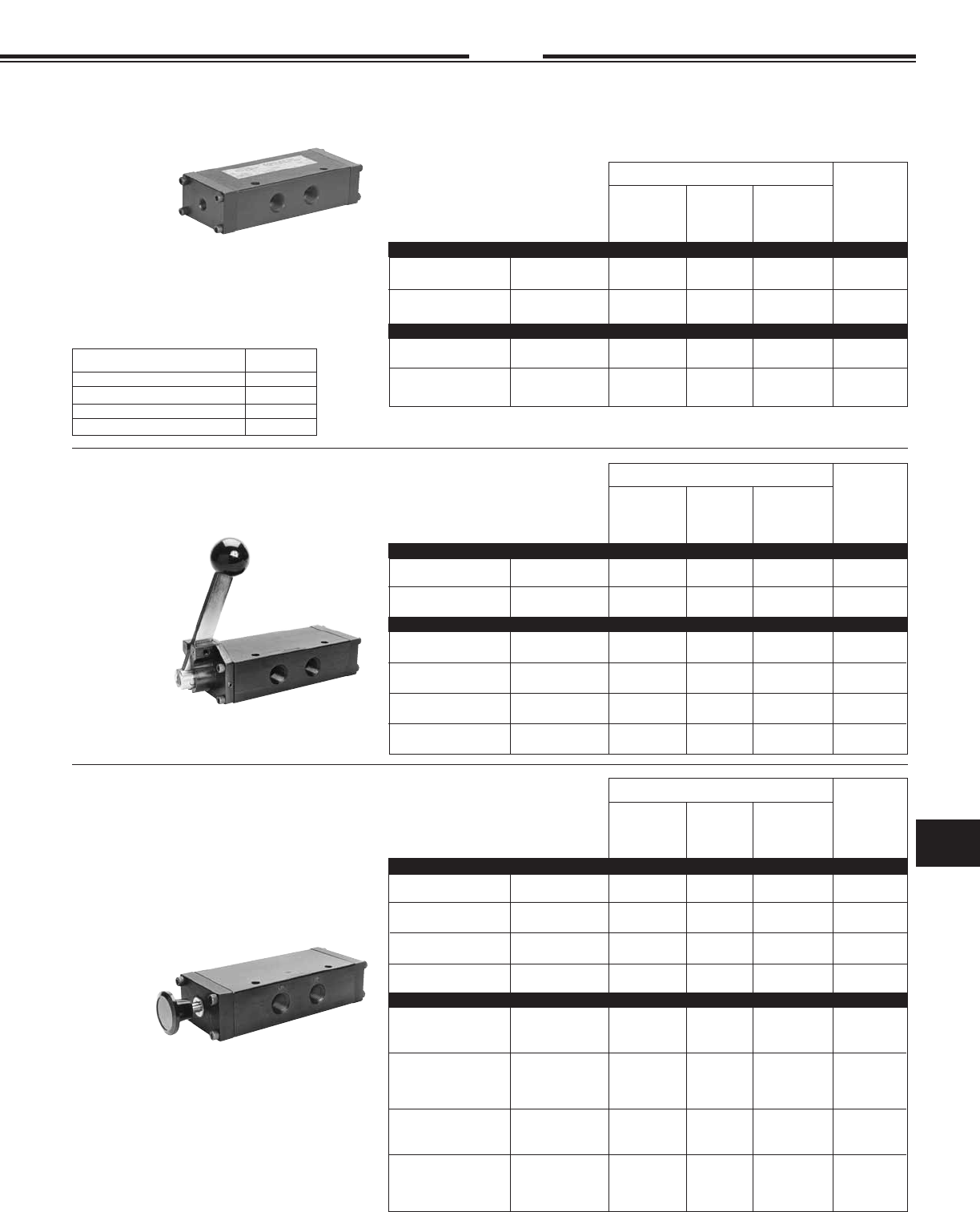
Specifi cations subject to change without notice or incurring obligation
11
Directional Control Valves
11.24
7-28-04
12, 12A, 12B & 38 Series
3/8 & 1/2
NPT
PILOT OPERATED
When Ordering:
Specify Model Number from chart. Specify Options.
(See page 11.27 & 11.28 for Dimensional Information.)
Push - Pull 2 Way - 3 Way 383-PO 123-PO 123B-PO NA
(Natural Detent) 4 Way 38-PO 12-PO 12B-PO 12A-PO
Push 2 Way - 3 Way 383-PS 123-PS 123B-PS NA
Spring Return 4 Way 38-PS 12-PS 12B-PS 12A-PS
Push 2 Way - 3 Way 383-PA 123-PA 123B-PA NA
Pilot Return 4 Way 38-PA 12-PA 12B-PA 12A-PA
Push - Push 2 Way - 3 Way 383-PP 123-PP 123B-PP NA
Knob Both Ends 4 Way 38-PP 12-PP 12B-PP 12A-PP
Push - Pull
Spring Centered 4 Way 38-PB 12-PB NA 12A-PB
Type B Spool
Push - Push
Spring Centered 4 Way 38-PPB 12-PPB NA 12A-PPB
Knob Both ends
Type B Spool
Push - Pull
Spring Centered 4 Way 38-PF 12-PF NA 12A-PF
Type F Spool
Push - Push
Spring Centered 4 Way 38-PPF 12-PPF NA 12A-PPF
Knob Both ends
Type F Spool
2 Position
LOCKING -MO1
LOCKS IN - Does not lock OUT -MO2
Does not lock IN - LOCKS OUT -MO3
NON-LOCKING -MO4
Optional Manual Overrides Model Suffi x
1/2 NPT
3/8 NPT 1/2 NPT High Flow
SUBBASE
OR
MANIFOLD
MOUNTED
See pg 11.27
and Specify
Direct Ported
3 Position
Spring Return 2 Way - 3 Way 383-HLS 123-HLS 123B-HLS NA
4 Way 38-HLS 12-HLS 12B-HLS 12A-HLS
Detented 2 Way - 3 Way 383-HL 123-HL 123B-HL N
4 Way 38-HL 12-HL 12B-HL 12A-HL
Spring Centered 4 Way 38-HLSB 12-HLSB NA 12A-HLSB
Type B Spool
Spring Centered 4 Way 38-HLSF 12-HLSF NA 12A-HLSF
Type F Spool
Detented 4 Way 38-HLB 12-HLB NA 12A-HLB
Type B Spool
Detented 4 Way 38-HLF 12-HLF NA 12A-HLF
Type F Spool
2 Position
1/2 NPT
3/8 NPT 1/2 NPT High Flow
SUBBASE
OR
MANIFOLD
MOUNTED
See pg 11.27
and Specify
Direct Ported
3 Position
HAND LEVER OPERATED
When Ordering:
Specify Model Number from chart. Specify Options.
(See page 11.27 & 11.28 for Dimensional Information.)
PUSH-PULL KNOB OPERATED
When Ordering:
Specify Model Number from chart. Specify Options.
(See page 11.27 & 11.28 for Dimensional Information.)
OPERATING RANGE:
Inlet Presure . . . . . . . . . . . . . . . . . .0 - 150 psi
Pilot Pressure:
Models without Spring . . . . . . . . . . . . . . . . . . .10 - 150 psi
2 Position Standard Service Spring . . . . . . . . .45 - 150 psi
2 Position Light Service Spring (Option -L) . . .30 - 150 psi
3 Position, Spring Centered . . . . . . . . . . . . . . .30 - 150 psi
Single Pilot 2 Way - 3 Way 383-SP 123-SP 123B-SP NA
Spring Return 4 Way 38-SP 12-SP 12B-SP 12A-SP
Double Pilot 2 Way - 3 Way 383-DP 123-DP 123B-DP N
4 Way 38-DP 12-DP 12B-DP 12A-DP
Double Pilot 4 Way 38-DPB 12-DPB NA 12A-DPB
Type B Spool
Double Pilot 4 Way 38-DPF 12-DPF NA 12A-DPF
Type F Spool
2 Position
1/2 NPT
3/8 NPT 1/2 NPT High Flow
SUBBASE
OR
MANIFOLD
MOUNTED
See pg 11.27
and Specify
Direct Ported
3 Position
OPERATING RANGE: . . . . . . . . . . . . . . . . . . .0 - 150 psi
OPERATING RANGE: . . . . . . . . . . . . . . . . . . .0 - 150 psi
Standard knob color is black.
For red knob add suffi x -R to Model Number.
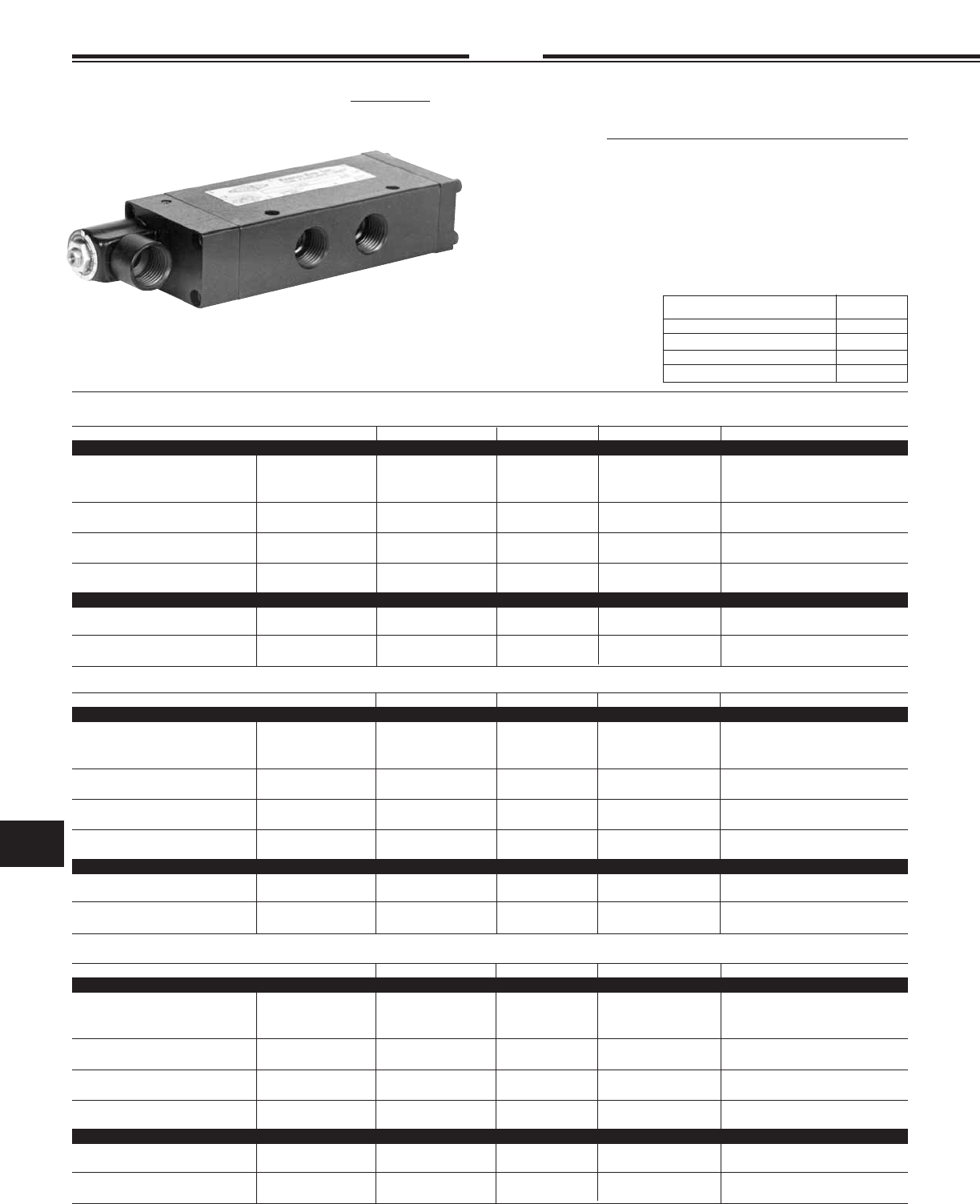
Specifi cations subject to change without notice or incurring obligation
Directional Control Valves
11
11.25 2-14-08
12, 12A, 12B & 38 Series
3/8 & 1/2
NPT
3/8 & 1/2 NPT Ported, 53 STYLE Solenoid Controlled, Pilot Operated Air Valves
2 Way, 3 Way - 2 Position — 4 Way 2 or 3 Position — Operation to 150 PSI Air
Operating Ranges, psi
Internal Pilot Supply (Standard) Inlet Pressure
No Spring . . . . . . . . . . . . . . . . . . . . . . . . . 10 to 150
Spring: 2 Position . . . . . . . . . . . . . . . . 45 to 150
2 Position Light Service Spring,
Option -L . . . . . . . . . . . . . 30 to 150
3 Position . . . . . . . . . . . . . . . . . 30 to 150
External Pilot Supply, Option -X:
Inlet Pressure . . . . . . . . . . . . . . . . . . . . . . 0 to 150
Pilot Pressure, Same as Internal Pilot Supply above.
See pages 11.27 & 11.28 for
dimensional information.
LOCKING -MO1
LOCKS IN - Does not lock OUT -MO2
Does not lock IN - LOCKS OUT -MO3
NON-LOCKING -MO4
Optional Manual Overrides Model Suffi x
When Ordering:
Specify Model Number from Chart
Specify Options
Specify Volts / Hertz
See pages 11.29 & 11.30 for Solenoid Operator,
Coil and Housing information.
Grommet Housing “G”
3/8 NPT 1/2 NPT 1/2NPT High Flow Sub-base/Manifold, See Pg. 11.27
Single Solenoid 2 / 3 Way, NC 383–FS 123–FS 123B–FS NA
Spring Return 2 / 3 Way, NO 3830–FS 1230–FS 1230B–FS NA
4 Way 38–FS 12–FS 12B–FS 12A–FS
Single Solenoid 2 / 3 Way 383–FA 123–FA 123B–FA NA
Pilot Return 4 Way 38–FA 12–FA 12B–FA 12A–FA
Single Solenoid 2 / 3 Way 383–FP 123–FP 123B–FP NA
Knob Return 4Way 38–FP 12–FP 12B–FP 12A–FP
Double Solenoid 2 / 3 Way 383–FF 123–FF 123B–FF NA
4 Way 38–FF 12–FF 12B–FF 12A–FF
Solenoid – Pilot, B Spool 4 Way 38–FAB 12–FAB NA 12A—FAB
Solenoid – Pilot, F Spool 4 Way 38–FAF 12–FAF NA 12A–FAF
Double Solenoid – B Spool 4 Way 38–FFB 12–FFB NA 12A—FFB
Double Solenoid – F Spool 4 Way 38–FFF 12–FFF NA 12A–FFF
2 Position
3 Position
Male Mini-DIN Housing “F”
3/8 NPT 1/2 NPT 1/2NPT High Flow Sub-base/Manifold, See Pg. 11.27
Single Solenoid 2 / 3 Way, NC 383–GS 123–GS 123B–GS NA
Spring Return 2 / 3 Way, NO 3830–GS 1230–GS 1230B–GS NA
4 Way 38–GS 12–GS 12B–GS 12A–GS
Single Solenoid 2 / 3 Way 383–GA 123–GA 123B–GA NA
Pilot Return 4 Way 38–GA 12–GA 12B–GA 12A–GA
Single Solenoid 2 / 3 Way 383–GP 123–GP 123B–GP NA
Knob Return 4Way 38–GP 12–GP 12B–GP 12A–GP
Double Solenoid 2 / 3 Way 383–GG 123–GG 123B–GG NA
4 Way 38–GG 12–GG 12B–GG 12A–GG
Solenoid – Pilot, B Spool 4 Way 38–GAB 12–GAB NA 12A—GAB
Solenoid – Pilot, F Spool 4 Way 38–GAF 12–GAF NA 12A–GAF
Double Solenoid – B Spool 4 Way 38–GGB 12–GGB NA 12A—GGB
Double Solenoid – F Spool 4 Way 38–GGF 12–GGF NA 12A–GGF
2 Position
3 Position
3/8 NPT 1/2 NPT 1/2NPT High Flow Sub-base/Manifold, See Pg. 11.27
Single Solenoid 2 / 3 Way, NC 383–CS 123–CS 123B–CS NA
Spring Return 2 / 3 Way, NO 3830–CS 1230–CS 1230B–CS NA
4 Way 38–CS 12–CS 12B–CS 12A–CS
Single Solenoid 2 / 3 Way 383–CA 123–CA 123B–CA NA
Pilot Return 4 Way 38–CA 12–CA 12B–CA 12A–CA
Single Solenoid 2 / 3 Way 383–CP 123–CP 123B–CP NA
Knob Return 4Way 38–CP 12–CP 12B–CP 12A–CP
Double Solenoid 2 / 3 Way 383–CC 123–CC 123B–CC NA
4 Way 38–CC 12–CC 12B–CC 12A–CC
Solenoid – Pilot, B Spool 4 Way 38–CAB 12–CAB NA 12A—CAB
Solenoid – Pilot, F Spool 4 Way 38–CAF 12–CAF NA 12A–CAF
Double Solenoid – B Spool 4 Way 38–CCB 12–CCB NA 12A—CCB
Double Solenoid – F Spool 4 Way 38–CCF 12–CCF NA 12A–CCF
2 Position
3 Position
Conduit Housing “C”
Operating Temperature:
0°F (–18°C) to +104°F (40°C) ambient.
0°F (–18°C) to +150°F (65°C) media.
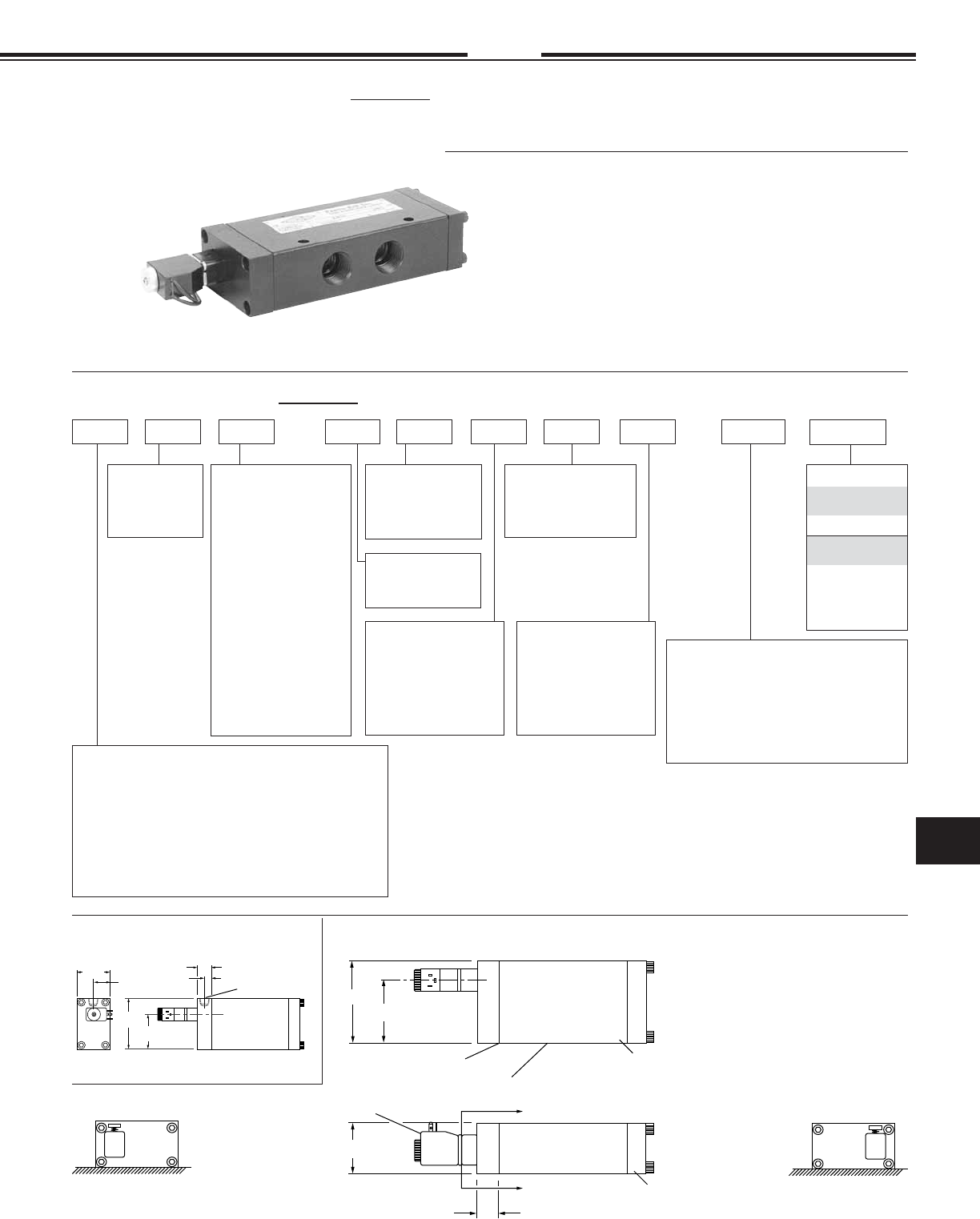
Specifi cations subject to change without notice or incurring obligation
11
Directional Control Valves
11.26
1-26-08
12, 12A, 12B & 38 Series
3/8 & 1/2
NPT
1
3
Primary Solenoid
Manual Override
Position
Section A – A
2
4
1
3
2
4
Secondary Solenoid
Manual Override
Position
Section A – A
1/8 NPT
1.50
1.70
.75
External Pilot Supply Option -X
2.50
.63
.31
Primary Actuator End
2.50
1.96
Spring Return
Shown
1.50
Secondary Actuator End
A
A
Side View
3 or 4 Way
Valve Body
See page 11.27
for Body Details
See page 11.31
for Operator Details
.63
58 STYLE Solenoid Valve, Model Number Code
Primary Actuator
F = Micro DIN
G = Wire leads
See page 11.31
12 FS4510 120/60——
Primary Solenoid
Attitude
5 = Inline with Body
Primary Solenoid
Manual Override
0 = None
1 = Position #1
2 = Position #2
3 = Position #3
4 = Position #4
Secondary Solenoid
Attitude
0 = Other than Solenoid
5 = Inline with Body
Volts / Hertz
#1 Solenoid
(0.9 Watts)
12 VDC, 24 VDC
#4 Solenoid
(3.5 Watts)
24/60 VAC
120/60 VAC
12 VDC
24 VDC
Example: 12FS-45100-120/60
1/2 NPT, 4 Way – Primary Actuator Solenoid with Micro DIN coil; Sec-
ondary Actuator, Spring Return – 3.5 Watt; Primary Solenoid Inline
Attitude with Manual Override on Primary Solenoid in Position #1;
Secondary Actuator is not a Solenoid; no Manual Override on Sec-
ondary Actuator – No Options – 120 Volt/60 Hertz.
Secondary Solenoid
Manual Override
0 = None
1 = Position #1
2 = Position #2
3 = Position #3
4 = Position #4
0
Secondary Actuator
F = Micro DIN, 2 Pos.*
FB = Micro DIN
3 Position Type B*
FF = Micro DIN
3 Position Type F*
G = Wire leads, 2 Pos.*
GB = Wire leads
3 Position Type B*
GF = Wire leads
3 Position Type F*
S = Spring**
A = Pilot**
P = Knob (Black)**
PR = Knob (Red)**
* See page 11.23, 11.31.
** See pages 11.24 &
11.28 for details.
Options
-X = External Pilot
-XV = † External Pilot & Viton Seals
-L = Light Spring
†
Viton Seals are available in the main valve
only for media compatability and therefore only
in conjunction with
External Pilot [0°F (–18°C) to +122°F (50°C)].
Series: 38 = 3/8 NPT, 4 Way
383 = 3/8 NPT, 3 Way NC
3830 = 3/8 NPT, 3 Way NO
12 = 1/2 NPT, 4 Way
123 = 1/2 NPT, 3 Way NC
1230 = 1/2 NPT, 3 Way NO
12A = 4 Way, Subbase Mount
12B = 1/2 NPT, 4 Way, 2 Position High Flow
123B = 1/2 NPT, 3 Way NC, High Flow
1230B = 1/2 NPT, 3 Way NO, High Flow
Solenoid Watts
1 = 0.9 Watts
4 = 3.5 Watts
Inline
Solenoid Attitude #5
(Solenoid centerline inline
with Valve Body centerline)
3/8 & 1/2 NPT Ported, 58 STYLE Solenoid Controlled, Pilot Operated Air Valves
2 Way, 3 Way - 2 Position — 4 Way 2 or 3 Position
Spring Return and Spring Centered Models NOT suitable for dry air service
#1 Solenoid #4 Solenoid
0.9 Watts 3.5 Watts
Internal Pilot Supply (Standard) Inlet Pressure
No Spring: . . . . . . . . . . . . . . . . . . . .10 to 130 . . . .10 to 145
Spring: 2 Position . . . . . . . . . . . .45 to 130 . . . .45 to 145
2 Position Light Service Spring,
Option -L . . . . . . . . . . . . . . . . . . . .30 to 130 . . . .30 to 145
3 Position . . . . . . . . . . . .30 to 130 . . . .30 to 145
External Pilot Supply, Option -X:
Inlet Pressure . . . . . . . . .0 to 150 . . . . .0 to 150
Pilot Pressure, Same as Internal Pilot Supply above.
Operating Ranges, psi
See pages 11.27 & 11.28 for other
dimensional information, 11.31 for
solenoid information.
Operating Temperature:
0°F (–18°C) to +122°F (50°C) ambient.
0°F (–18°C) to +122°F (50°C) media.
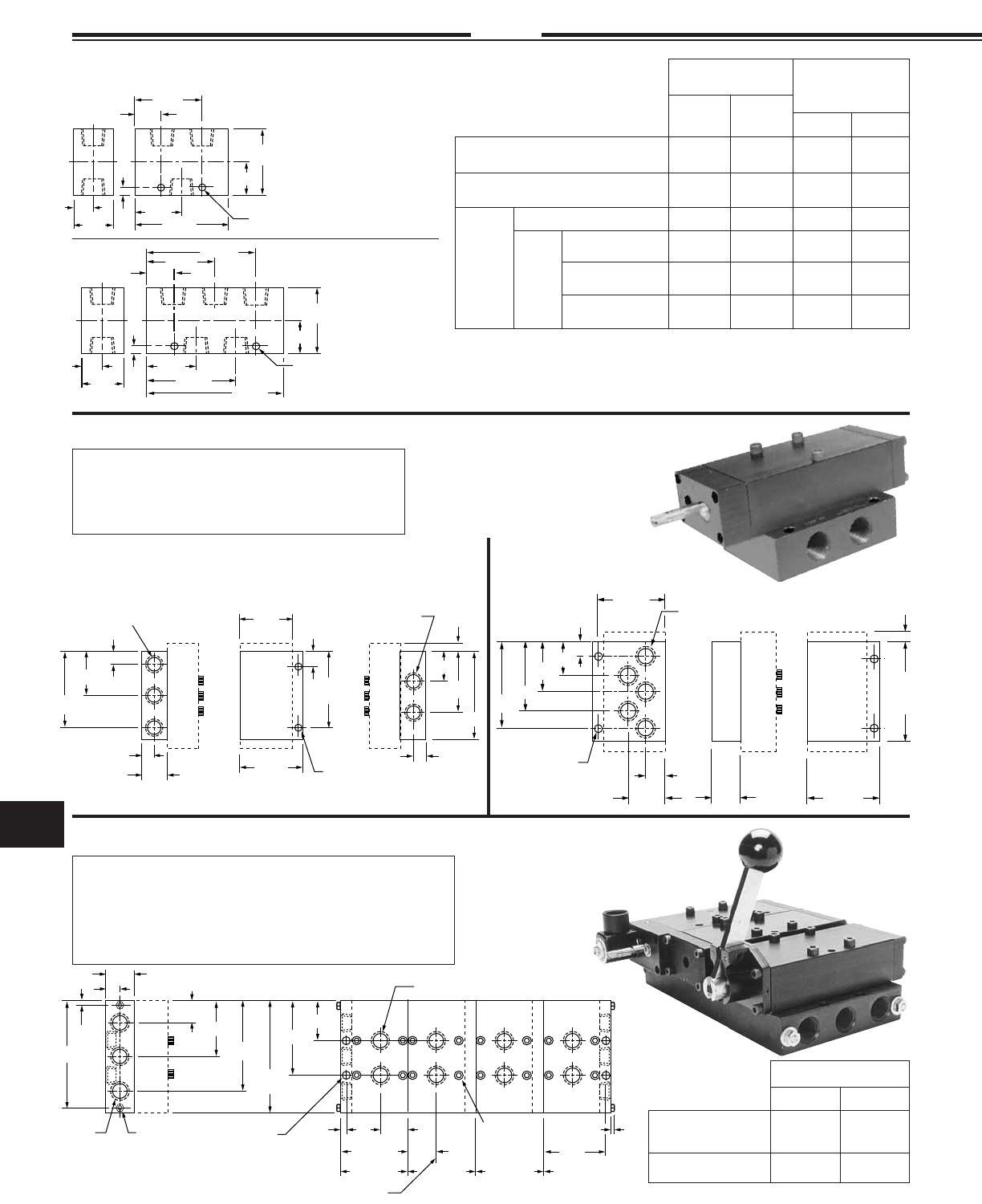
Specifi cations subject to change without notice or incurring obligation
Directional Control Valves
11
4.00
1.25
2.50
1.00
.62
Basic
Body
Outline
5
1
3
Secondary
Primary
5.00
4
2
4
2
4
2
4
2
1.75
3.25
1/2 NPT
IN & EXH
Ports
3/8 or 1/2 NPT CYL Ports on Bottom
.25
1/4-20
Tie Rods
.34 Dia. Mounting
Holes - 2 Each End
Station 1 Station 2 Station 3 Station 4 Etc.
.22 1.28
1.28 TYP.
.25
2.78
Valve Body & CYL Port C
L
3.00 TYP.
1/4-20 x 2.00
S.H.C. Valve
Mounting
Screws
Top View
4.75
11.27 2-18-08
12, 12A, 12B & 38 Series
3/8 & 1/2
NPT
12 10
2
1.00
1
1.25
2.50
2.50
.27 Dia. Mounting
Hole, 2 Places
3
3.50
1.75
2 WAY (Plug 3 Way)
3 WAY
Spring Return
Assembly
Standard this End
Primary Secondary
.75
1.50 .31
12 14
2
1.00
1
1.25
2.50
2.50
.27 Dia.
Mounting
Hole,
2 Places
3
3.25
1.75
4 WAY
Spring Return
Assembly
Standard this End
Primary Secondary
.75
1.50 .31
4
5
4.00
5.00
3.63
1.25
2.13
.63
SIDE PORTED
3/8 NPT Ports Specify 38 PV-50
1/2 NPT Ports Specify 12 PV-50
.63
3/8 or 1/2 NPT IN & EXH Ports 3/8 or 1/2 NPT CYL Ports
Basic
Body
Outline
Basic
Body
Outline
Secondary
Primary
1.38
2.88
4.25
.38
2.75
3.00
.34 Dia. Mounting Holes
2 Places
5
13
4
2
3.63
.63
.63
BASIC BODIES
NOTE: Any of these 4-way valves, except the internally supplied solenoid valves (see
Option -X), can be used as dual inlet, single exhaust. Using this concept, with different
pressures for force application and retraction, can effect large savings of high pressure
air and its cost. The larger the cylinder or the faster the cycle, the higher the savings.
SINGLE SUBBASES
MULTIPLE MANIFOLDS
MOUNT ANY COMBINATION
OF 4 WAY VALVE MODELS
& PORT SIZES
To Order
Specify Station No. - Valve Model - Manifold Number
EXAMPLE -
Photo shows one unit consisting of 3 valves and manifolds:
Sta. No. 1 12A-CS-MO1 with 12 PV-65
Sta. No. 2 12A-DP with 12 PV-66
Sta. No. 3 12A-HL with 38 PV-65
Direct Ported
3/8 or 1/2 1/2 NPT
NPT High Flow
4.1 6.2
4.1 6.2
2.4 NA
Subbase Mounted
Side or
Bottom Ported
3/8 NPT 1/2 NPT
NA NA
3.1 3.7
2.2 2.4
2-Way – 3-Way
2 Position - Type 3 Spool
4-Way
2 Position - Type 2 Spool
4
Way
3
Position
Type B Spool
Type
F
Spool
Shifted
1 to 2; 1 to 4 2.4 NA 2.2 2.3
Shifted
2 to 3; 4 to 5 4.1 NA 3.4 3.9
Centered
2 to 3; 4 to 5 2.7 NA 2.6 2.8
Cv FLOW FACTORS
To Order
Specify Valve Model No. (See pages 11.23 - 11.26)
Specify Subbase Part No. listed below.
EXAMPLE - Photo shows 12A-SP-MO4 with 12 PV-50
CYLINDER PORTS
3/8 NPT 1/2 NPT
End Unit
1/2 NPT IN & EXH
CENTER UNIT 38 PV-66 12 PV-66
38 PV-65 12 PV-65
MOUNT 4 WAY VALVE
WITH ANY OPERATOR
3.63
1.63
2.13
.63
.88
3/8 or 1/2 NPT IN,
CYL & EXH Ports
Basic
Body
Outline
Secondary
Primary
1.38
2.88
2.75
3.00
.34 Dia.
Mounting Holes
2 Places
5
1
3
4
2
4.25
.38
1.25
BOTTOM PORTED
3/8 NPT Ports Specify 38 PV-51
1/2 NPT Ports Specify 12 PV-51
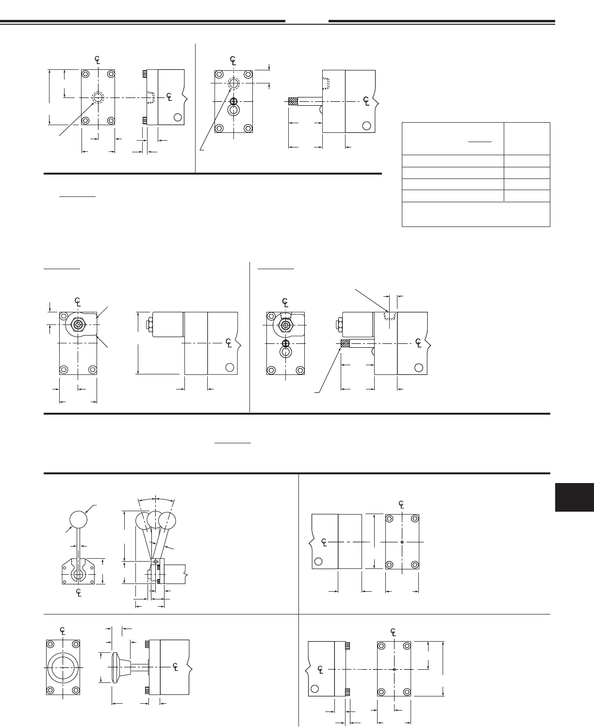
Specifi cations subject to change without notice or incurring obligation
11
Directional Control Valves
11.28
2-7-08
12, 12A, 12B & 38 Series
3/8 & 1/2
NPT
1.50
.50
.19
2.50
1.25
.75
Pilot Port
1/8 NPT
.85
Pilot Port
1/8 NPT
1.38
Max.
.88
Min.
.63
.85
2.50
.50
1.50
.75
Housing
Can
Rotate
360
See page 11.29 for
Operator Details
°
.85
Manual Override
See page
11.29 for
Operator
Details
1.38
Max.
.88
Min.
.28
Option -X
1/8 NPT External Pilot Supply
15
°
4.06
1.00
15
°
1.75
2.00
.63
.25
.63
2.25
1.38 Dia.
.28 Max.
1.38
Dia.
.50 Stroke
.81
1.65 .50
1.50
1.00
2.50
1.50
.50
.19
2.50
1.25
.75
AIR PILOT OPERATOR AIR PILOT OPERATOR
with Manual Override
2 Position, Spring return
Dimensions shown at the
bottom of the page.
3 Position Spring Centering
is incorporated within the
operator dimensions.
53 STYLE SOLENOID OPERATOR
with Manual Override and External Pilot Supply, Opption -X
53 STYLE SOLENOID OPERATOR
2 Position, Spring return
Dimensions shown at the
bottom of the page.
3 Position Spring Centering
is incorporated within the
operator dimensions.
The 53 STYLE solenoid operator is a 3-way valve which, upon receiving an electrical signal, directs a
pilot pressure to shift the main valve spool. Unless otherwise specifi ed, the operator is internally sup-
plied from the main valve inlet with pressure for piloting. If an external pilot supply is required specify
Suffi x -X after the model number. This external pilot supply may be required; where the media through
the main valve is of insuffi cient pressure for piloting, where the media through the main valve is some-
thing other than compressed air, for 4-way dual inlet-single exhaust, or other applications.
HAND LEVER
OPERATOR
PALM BUTTON
OPERATOR
2 Position, Spring return
Dimensions shown to right.
3 Position Spring Centering
is incorporated within the
operator dimensions.
2 POSITION
SPRING RETURN,
STANDARD &
LIGHT SERVICE
All valve models –
Standard service
spring consists of two
concentric helical springs.
Either may be removed
for “Light” Service.
3 POSITION SPRING
CENTERING OPERATOR
FOR HAND LEVER ONLY
58 STYLE Solenoid Operator – See page 11.26
LOCKING -MO1
LOCKS IN - Does not lock OUT -MO2
Does not lock IN - LOCKS OUT -MO3
NON-LOCKING -MO4
Note: The manual override stem
physically contacts and moves the spool.
Manual Overrides applicable
to Pilot Operated or 53 Style
Solenoid Operated Valves
To Specify
Add Suffi x to
Model Number
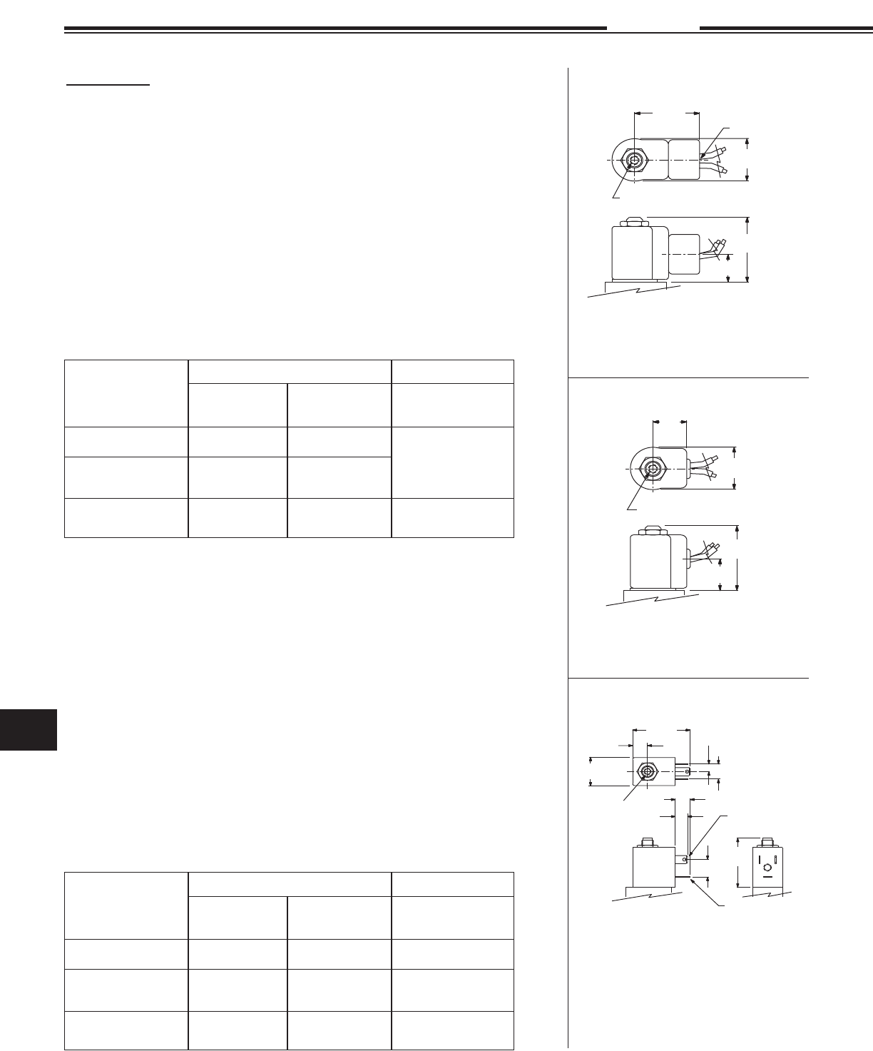
Specifi cations subject to change without notice or incurring obligation
Directional Control Valves
11
11.29 3-12-08
1.50
.63
1.03
1.25
1/2 NPT
10-32 Exhaust Port
Housing can rotate 360
°
1.03
10-32 Exhaust Port
1.50
.75
.63
Housing can rotate 360
°
1.58
.44
.88
10-32
Exhaust
Port
.43
.22
(11 mm)
spacing
.47
.37
.57 1.50
Line Terminals
.25 x .03
Ground Terminal
.25 x .03
Housing can rotate 360
°
53 STYLE Stocked Coils and Housings
Conduit Housing “C” and Grommet Housing “G”
Non-molded – Class A 221°F (105°C) Rating,
24" Leads of AWG #18 Wire.
Stocked Voltages:
24, 120 and 240 Volt at 50 or 60 Hertz;
6, 12 and 24 Volt DC;
Others available, see Options on page 11.30.
Temperature Range:
0°F (–18°C) to + 104°F (+40°C), ambient.
0°F (–18°C) to + 150°F (+65°C), media.
Typical Response Times:
AC 4 to 8 milliseconds to open or close;
DC 9 to 15 milliseconds to open;
DC 5 to 12 milliseconds to close.
To compute current requirements (±15%) divide factor shown below by voltage
Male Mini-DIN Housing “F”
Molded – Water Tight - Class A 221°F (105°C) IP65 Coil Rating.
European (DIN) Style – 11 mm spacing.
See page 11.30 for connectors or contact your
local distributor for additional choices.
Can also be connected with individual .25" quick connect terminals.
Stocked Voltages:
24, 120 and 240 Volt at 50 or 60 Hertz;
12 and 24 Volt DC;
Others available, see Options on page 11.30.
Temperature Range:
0°F (–18°C) to + 104°F (+40°C), ambient.
0°F (–18°C) to + 150°F (+65°C), media.
Typical Response Times:
AC 4 to 8 milliseconds to open or close;
DC 9 to 15 milliseconds to open;
DC 5 to 12 milliseconds to close.
To compute current requirements (±15%) divide factor shown below by voltage.
AC Volts, 60 Hertz DC Volts
Inrush, Amp
Function Inrush, Amp Holding, Amp or Holding, Amp
2 Way NC 14.4 ÷ Volts 9.7 ÷ Volts 10.4 ÷ Volts
2 Way NO
3 Way NC or NO
Examples 15.2 ÷ 120 = 11.8 ÷ 120 = 10.4 ÷ 12 =
.13 Amp .10 Amp .87 Amp
15.2 ÷ Volts 11.8 ÷ Volts 10.4 ÷ Volts
AC Volts, 60 Hertz DC Volts
Inrush, Amp
Function Inrush, Amp Holding, Amp or Holding, Amp
2 Way NC 13.2 ÷ Volts 7.8 ÷ Volts
2 Way NO
3 Way NC or NO
Examples 15.2 ÷ 120 = 9.0 ÷ 120 = 7.2 ÷ 12 =
.13 Amp .08 Amp .60 Amp
15.2 ÷ Volts 9.0 ÷ Volts 7.2 ÷ Volts
Conduit Housing “C”
Grommet Housing “G”
Male Mini-DIN Housing “F”
Spade terminals accept miniature
rectangular quick connect socket
(Female DIN style connector, 11 mm spac-
ing) or individual .25" quick
connect terminals.
Solenoid, Coil and Housing Information 53 Style
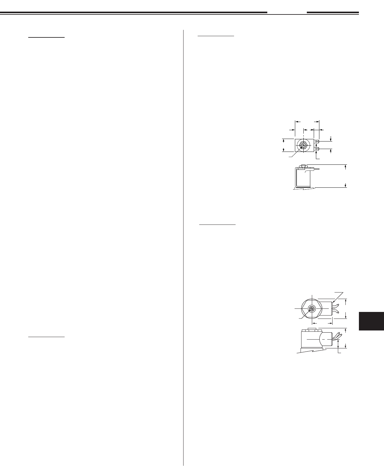
Specifi cations subject to change without notice or incurring obligation
11
Directional Control Valves
11.30
3-3-08
53 STYLE Options for
Conduit Housing “C” and
Grommet Housing “G”
AC Voltages from 5.4 to 575 in 50 or 60 Hertz.
DC Voltages from 3 to 300.
• Molded Coil . . . . . . . . . . . . . . . . . . . . . . . . . .Option -M
Water tight, Molded Coil with Class A 221°F
(105°C) Rating. Coil is completely molded in
epoxy for maximum moisture resistance.
NEMA 1, 2, and 3 when in
Conduit “C”, or Grommet “G” housing.
• Potted Coil . . . . . . . . . . . . . . . . . . . . . . . . . . . Option -P
Coil is epoxy potted into Conduit “C” housing only.
Class F 221°F (105C) Rating.
It offers maximum moisture and vibration resistance.
NEMA 3R, 3S, 4, 4X, 6, 11, 12 & 13.
• High Temperature . . . . . . . . . . . . . . . . . . . . . Option -H
Molded coil with 356°F (180°C) rating.
• Viton Seals
(for media compatibility) . . . . . . . . . . . . . . . Option -V
• Strain Relief Connector . . . . . . . . . . . . . . . . . Option -Q
• “AN” Connector . . . . . . . . . . . . . . . . . . . . . . Option -W
• Splice Box . . . . . . . . . . . . . . . . . . . . . . . . . . Option -J
• Mounting Bracket . . . . . . . . . . . . . . . . . . . . . Option -R
• Third Wire Ground . . . . . . . . . . . . . . . . . . . .Option -CC
A CSA requirement.
53 STYLE Options for
Male Mini-DIN Housing “F”
AC Voltages from 4.4 to 277 in 50 or 60 Hertz.
DC Voltages from 3 to 180.
• Viton Seals
(for media compatibility) . . . . . . . . . . . . . . Option -V
53 STYLE Options for Yoke Housing
• Yoke with Standard coil
(24" fl ying leads) . . . . . . . . . . . . . . . . . . . . . . . . . . Option -YB
• Yoke with Molded coil
(24" fl ying leads) . . . . . . . . . . . . . . . . . . . . . . . . . . Option -YM
• Yoke with Molded
Spade Terminal and coil . . . . . . . . . . . . . . . . . . . .Option -KM
Yoke replaces housing
for protected and control box
applications. Molded coil with
two .25" spade terminals for
quick assembly and
disconnect.
Solenoid, Coil and Housing Information 53 Style
1.53
1.60
1.44
.75
Housing can rotate 360
°
1/2 NPT
10-32
Exhaust
Port
.60
1.67
.33
.60
.25 x .03 Thick
1.50 Flying Leads Coil
1.74 Spade Coil
10-32
Exhaust
Port
1.03
53 STYLE Explosion Proof . . . . . . . . Option -EP
UL File #E37780
CSA File #LR-26894
For hazardous locations, includes Molded Coil.
UL Class I Div. 1 Groups C & D.
UL Class II Div. 1Groups E, F & G.
UL Class II Div. 2 Groups A, B, C, D, E & F.
NEMA 7 Class 1 Group D.
NEMA 9 & 9A Class II Groups F & G.
! CAUTION !
To prevent explosion,
disconnect electrical circuit
before opening enclosure!
Keep tightly closed when
in operation.
Option -EP Current Factors
AC Volts, 60 Hertz Inrush . . . . . . . . . . . . . Holding
2 Way NC 16.0 . . . . . . . . . . . . . . . . . . 7.8
2 Way NO 16.9 . . . . . . . . . . . . . . . . . 10.7
3 Way NC or NO 16.9 . . . . . . . . . . . . . . . . . 10.7
DC Volts Inrush or Holding
2 Way NC or NO 7.2
3 Way NC or NO 7.2
Divide “Factor” shown above by Volts to fi nd current.
See examples on opposite page.
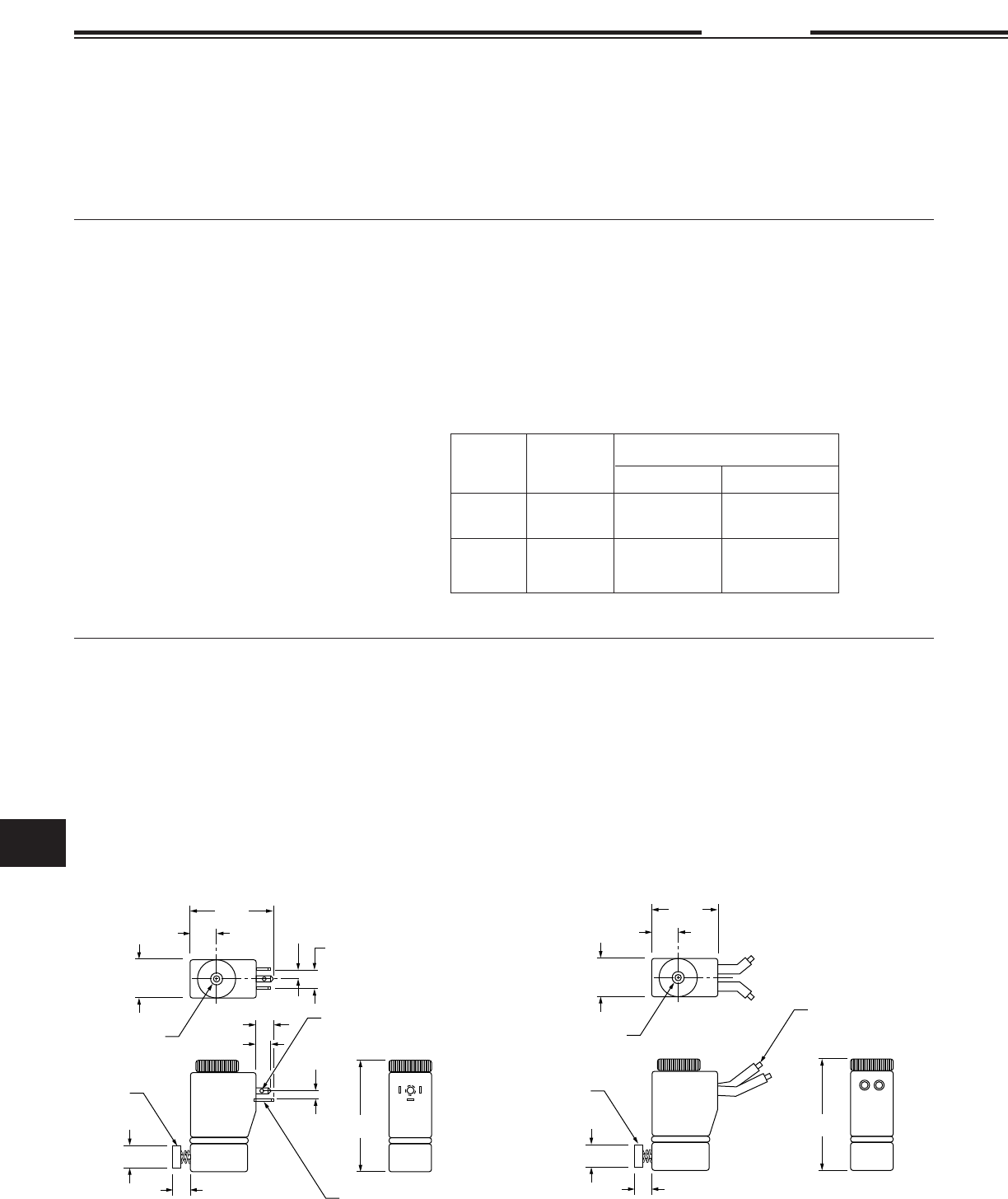
Specifi cations subject to change without notice or incurring obligation
Directional Control Valves
11
Specifi cations subject to change without notice or incurring obligation
Directional Control Valves
11
11.31 3-12-08
1.36
.44
.63
.30
.27
.19
.19
1.89
Ground Terminal
.14 x .02
.37 (9.4mm) Spacing
Line Terminal
.11 x .02
Exhaust Port
.38 Dia.
.25
Manual override
if ordered
1.06
.44
.63
1.89
AWG #20
18" Long
Exhaust Port
.38 Dia.
.25
Manual override
if ordered
58 Style
[#1 (0.9 Watts), or #4 (3.5 Watts)] Operator
58 Style
[#1 (0.9 Watts), or #4 (3.5 Watts)] Operator
Amperage Draw, mA
Volts Hertz Inrush Holding
24 60 252 220
120 60 43 37
12 DC 294 294
24 DC 145 145
58 Style
3 Way – Normally Closed – Exhaust to Atmosphere
Temperature Range:
0°F (–18°C) to + 122°F (+50°C), ambient.
0°F (–18°C) to + 122°F (+50°C), media.
Available with or without Push Button Manual Override
Solenoid, Coil and Housing Information 58 Style
#4 Operator
3.5 Watts
Volts – See Chart at Right
Amperage Draw – See Chart at Right
Response time: 8 ms with DC Volts;
3 – 9 ms with AC Volts.
1.0 mm Inlet Orifi ce – 1.0 mm Exhaust Orifi ce
145 psi Maximum Operating Pressure
#1 Operator
0.9 Watts
Volts – . . . . . . . . . . . . . . . . . . . . . . . 12 VDC . . . 24 VDC
Amperage Draw – (approximate) . . . .73 mA . . . . 37 mA
Response time: 9 ms @ 0 psi
0.6 mm Inlet Orifi ce – 0.8 mm Exhaust Orifi ce
130 psi Maximum Operating Pressure
Male Micro-DIN, Coil “F”
Molded – Water Tight
Class A 221°F (105°C ) IP65 Coil Rating
European (DIN) Style – 9.4 mm spacing
See page 11.32 for connectors or contact your
local distributor for additional choices.
Wire Leads, Coil “G”
Molded – Water Tight
Class A 221°F (105°C) IP65 Coil Rating
Leadwires – AWG #20, 18 inches long
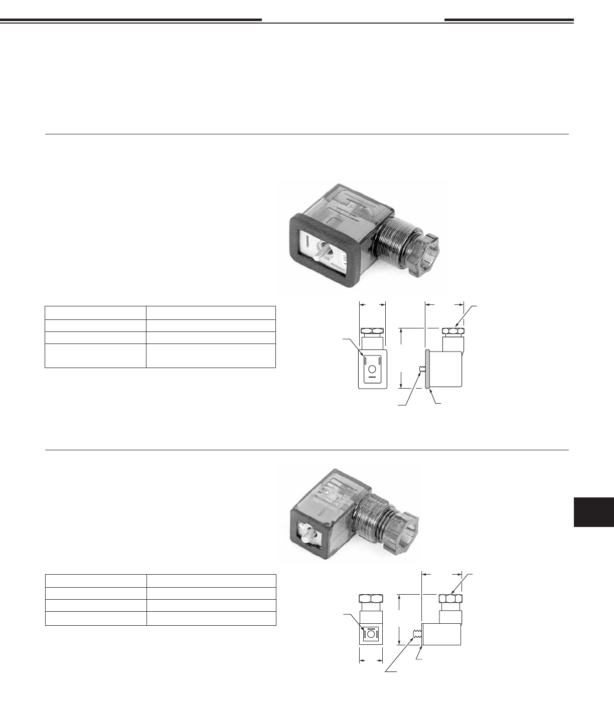
Specifi cations subject to change without notice or incurring obligation
11
Directional Control Valves
Specifi cations subject to change without notice or incurring obligation
11
Directional Control Valves
11.32
5-15-12
Solenoid Accessories 53 & 58 Style
Solenoid Exhaust Muffl ers, #SM-10
for "C" & "G" housings and "F" DIN coil operators. See page 14.1.
Flat Gasket, Nitrile Ribber
Housing can rotate around receptacle, in 90
increments, to locate cable in desired attitude.
M3 Connector Screw
1.02
1.38
.61
Receptacle with
9.4 mm spacing
mates with
Micro-DIN Coil “F”
.26 Max. Cable Dia.
18 Ga. Max. Wire Dia.
°
Part Number without LED: . . . . . . . . . . . . . . . . . . . 192-07-N
Black Housing (250v max. DC or AC 50/60 Hz)
Connectors 58 Style (9.4 mm Spacing)
NEMA 4, IP65
For Male Micro-DIN Housing “F”:
Connectors 53 Style
(11 mm spacing)
NEMA 4, IP65
For Male Mini-DIN Housing “F”
Part Number without LED: . . . . . . . . . . . . . . . . 122-09-N
Black Housing (300v max. DC, 250v max. AC 50/60 Hz)
Part Number with LED: Application
122-09-T-A.1-12VDC 12 VDC
122-09-T-A.1-24/60 24 VDC, 12-24 VAC 50/60 Hz
122-09-T-A.1-120/60 48-120 VDC,
100-240 VAC 50/60 Hz
Profile Gasket, Nitrile Ribber
Housing can be rotated
around receptacle, in 180
°
increments, to locate cable
in desired attitude.
M3 Connector Screw
1.18
2.00
Receptacle with
11 mm spacing
mates with
Mini-DIN
Housing “F”
.24 – .27 Cable Diameter
16 Ga. Max. Wire Diameter.
.79
.
(Transparent Housing allows LED to be seen)
Part Number with LED: Application
192-07-T-A.1-12/60 12 VDC or VAC 50/60 Hz
192-07-T-A.1-24/60 24 VDC or VAC 50/60 Hz
192-07-T-A.1-120/60 110-240 VDC or VAC 50/60 Hz
(Transparent Housing allows LED to be seen)
