Flow Fabco Air Sc Series Clamp Cylinders 1505484123 User Manual
Fabco-Air Sc Series Clamp Cylinders-1505484123 FABCO-AIR_SC_SERIES_CLAMP_CYLINDERS-1505484123
2017-10-06
User Manual: Flow Fabco-Air Sc Series Clamp Cylinders-1505484123
Open the PDF directly: View PDF ![]() .
.
Page Count: 4
Page 1
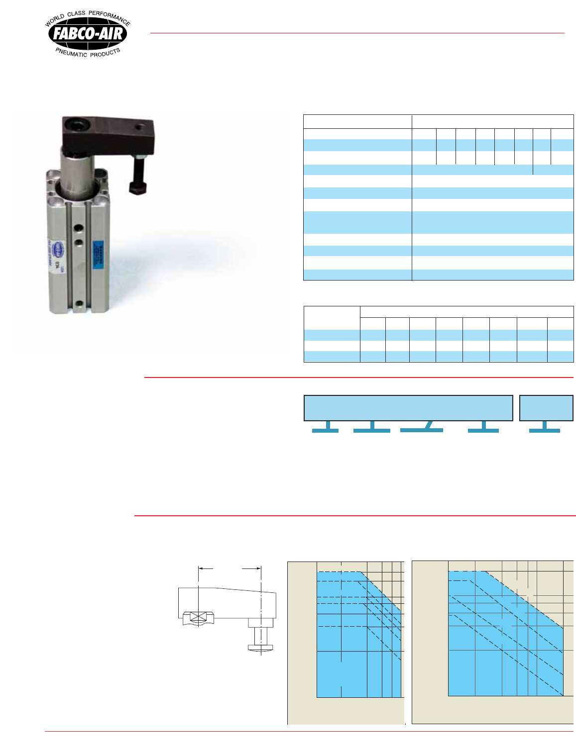
1) Vertical (rod up or rod down) applications only. 2) Swing portion of stroke is only to be used to align a clamp arm to the workpiece. Do
not attempt to use the swing stroke to apply forces to the work piece. 3) Make certain the cylinder applies loads only in the straight portion
of stroke, the loaded surface of
the workpiece is perpendicular
to the clamp cylinder axis and
that the workpiece will not move
to create a rotational force
when clamped. 4) Clamp Arm
Attachments: When removing
or attaching the clamp arm,
brace the arm with a wrench
or hold it steady in a vise. Not
doing so may damage the
internal parts of the clamp cylinder. 5) Operating Pressure:
Max. operating pressure should be determined based on
Dim. “X of either standard or custom length clamp
arm. 6) Piston / Clamp Speed: Use fl ow control valves to
limit piston speed to not greater than limits shown.
Bulletin #SC-DB04
NEW PRODUCT BULLETIN
Swing Clamp Cylinders featuring. . .
“SC” Series
7-23-07
Precautions
Operating Pressure (psi)
29 116
87
58
Clamping Arm Length (mm) Dim. X
145
20
40
60
80
100
200
SC12
SC16
Allowable
Operating
Range
SC20, 25
SC50, 63
SC32, 40
14
How to Order
Specifi cations
1) Specify “SC”
2) Specify the bore
3) Specify the straight stroke
4) Specify direction of swing
The clamp arm rotates 90° as
it extends away from the workpiece
providing clearance and ac-
cess for unload/load operations.
Double acting operation and standard
magnetic piston offer positive cycles,
durability and workpiece detection
features. Extruded aluminum body mounts
directly and rigidly to equipment surfaces in a
minimum of space.
Operation cycle:
1) Clamp arm extends (straight line) as it
releases clamp load from workpiece.
2) Arm rotates 90° to full extend position.
3) When retracting, clamp arm swings 90°:
Model Code R = clockwise direction,
Model Code L = counterclockwise rotation.
4) With clamp arm in position over the
workpiece, it follows a straight line path to
apply clamping force.
• Magnetic Piston • Clamp arm with adjusting bolt • Four rod end fl ats for clamp arm positioning
all included as standard at no extra charge!
Specifi cations and pricing subject to change without notice or incurring obligation
Piston Speeds (mm/sec)
20 806040 100 200
Clamping Arm Length (mm) Dim “X”
20
40
60
80
100
200
SC50, 63
SC12, 16
SC20, 25
SC32, 40
Weights (lbs)
Straight Stroke SC12 SC16 SC20 SC25 SC32 SC40 SC50 SC63
10 0.15 0.22 0.55 0.62 1.10 1.31 – –
20 0.19 0.27 0.64 0.71 1.16 1.41 2.42 3.35
50 – – – – – – 2.98 3.98
Model
Note:
a) Please order sensors separately from page 4.
b) Please order Flange Kits separately from page 3.
c) Swing Clamp Arm, four Wrench Flats and Magnetic
Piston are included as standard at no extra charge.
Competition charges extra for these essential features!
Action Double Acting, Magnetic Piston
Bore Size (mm) 12 16 20 25 32 40 50 63
Max. Moment (ft-lbs*) 0.73 2.8 5.1 9.5 19.9 34.6 78.9 134.2
Swing Stroke (mm) 7.5 7.5 10 10 13 13 18 18
Straight Stroke (mm) 10, 20 20, 50
Direction of Swing R-Clockwise; L-Counter Clockwise
Angle of Swing 90° ± 10°
Theoretical Clamping Force (lbs) See chart on page 2
Operating Media Compressed Air or
Petroleum Based Hydraulic Fluid
Max. Operating Pressure 145 psi (10 bar) - See “Precautions”
Piston Speed 50 to 100 mm/sec
Temperature Range -10° to + 70°C (+14° to 158°F)
Lubrication Air line lubrication recommended
* Max. bending moment allowed when retracting
Dim. X
See Page 3
Series
SC 25
x 20 R
Bore (mm)
ø12, ø16, ø20
ø25, ø32, ø40
ø50, ø63
Direction of Swing
when retracting
R - Clockwise
L - Counter Clockwise
Straight
Stroke (mm)
10: ø12 - ø40
20: ø12 - ø63
50: ø50, ø63
Ports
Blank = NPT
P = BSP Taper
Page 2
“SC” Swing Clamp Cylinders
4-12-04
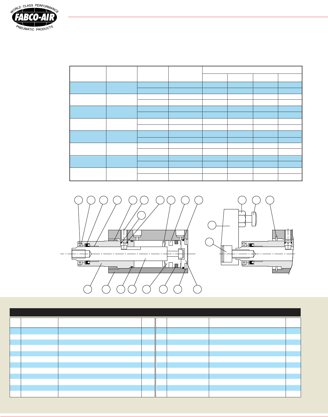
Construction
1 233 4 2765
16
17 18 148 9 19 10 11 15 12 13 21 22
20
24
Theoretical Output (lbs)
Model
SC12
SC16
SC20
SC25
SC32
SC40
SC50
SC63
Piston Rod
(mm)
6
8
12
12
16
16
20
20
Action
Retract
Extend
Retract
Extend
Retract
Extend
Retract
Extend
Retract
Extend
Retract
Extend
Retract
Extend
Retract
Extend
Piston
Area (in2)
0.13
0.17
0.23
0.31
0.32
0.49
0.59
0.76
0.94
1.25
1.64
1.95
2.56
3.04
4.35
4.83
60
7.8
10.2
13.8
18.6
19.2
29.4
35.4
45.6
56.4
75.0
98.4
117.0
153.0
182.0
261.0
289.0
80
10.4
13.6
18.4
24.8
25.6
39.2
47.2
60.8
75.2
100.0
131.2
156.0
204.0
243.0
348.0
386.0
100
13
17
23
31
32
49
59
76
94
125
164
195
256
304
435
483
40
5.2
6.8
9.2
12.4
12.8
19.6
23.6
30.4
37.6
50.0
65.6
78.0
102.0
121.0
174.0
193.0
Operating Pressure (psi)
Specifi cations and pricing subject to change without notice or incurring obligation
Quick Reference to Components
No. Description Material Qty.
13 Bumper Buna-N 1
14 Snap ring carbon steel 1
15 Set screw carbon steel 1
16 Clamp arm carbon steel, black treated 1
17 Nut carbon steel 1
18 Adjustable screw carbon steel 1
19 Rod seal Buna-N 1
20 Pin seal Buna-N 1
21 Piston seal Buna-N 1
22 Cover seal Buna-N 1
23 Front cover seal Buna-N 1
24 Fastening bolt carbon steel 1
No. Description Material Qty.
1 Front end cover anodized aluminum alloy 1
2 Rear end cover anodized aluminum alloy 1
3 Housing hard anodized aluminum alloy 1
4 Piston rod hard chrome plated carbon Steel 1
5 Piston aluminum alloy 1
6 Magnet magnet 1
7 Snap ring carbon steel 1
8 Snap ring carbon steel 1
9 Washer bronze 1
10 Bushing oil fi lled, sintered bronze 1
11 Fastening nut carbon steel, black treated 1
12 Positioning pin carbon steel 1
FABCO-AIR0UJ • 3716 N.E. 49th Avenue • Gainesville, FL 32609 • Tel (352) 373-3578
• Fax (352) 375-8024 • E-Mail: fabco@fabco-air.com • Web Site: www.fabco-air.com
Page 3
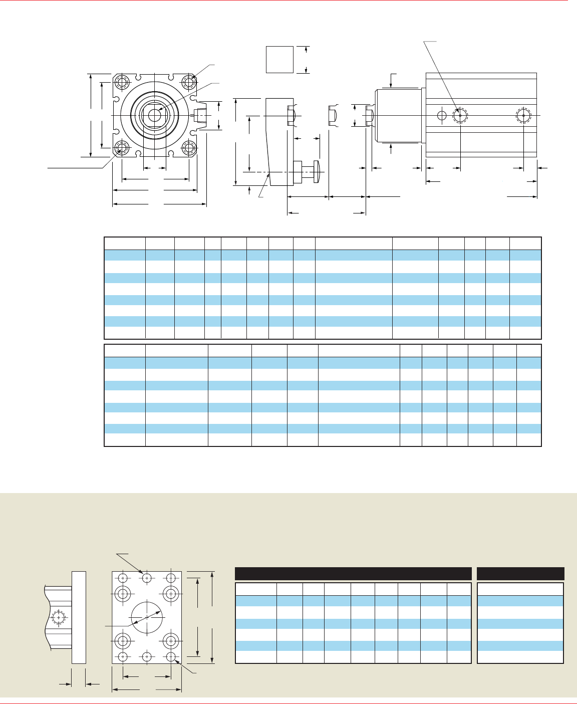
Dimensions
Dimensions (mm)
Mounting Flange
FX FZ
FY
FV
FT
FD – 4 Places
Mounting Hole
ØJ – 2 Places
for Positioning Pin
ØT
C
E
M
K
Z
EM
8–ØO C'Bore
4–ØN Thru Hole
H Threads
T 8 Places
øD
F
A + (2 x Straight Stroke)
Q
B + Straight Stroke
QQ
P Port 2 Places
NPT or BSP Taper
See Page 1 “How to Order”
Straight
Stroke
Swing
Stroke
Y
X
XX
HH
HX
V Square
øG
W
Total Stroke
6-25-07
A
48.0
48.0
72.5
73.5
94.0
94.0
112.0
114.0
B
35.5
35.5
62.0
63.0
72.0
65.0
77.0
80.0
F
2.5
2.5
3.0
3.0
5.5
5.5
5.5
5.5
M
15.5
20.0
25.5
28.0
34.0
40.0
50.0
60.0
E
25
29
36
40
45
52
64
77
Model
SC12
SC16
SC20
SC25
SC32
SC40
SC50
SC63
C
2
2
3
3
4
4
4
4
G
-
-
20
23
30
30
37
48
D
6
8
12
12
16
16
20
20
H Threads - Dp.
M3 x 0.5 - 5.5 Dp.
M5 x 0.8 - 6.5 Dp.
M8 x 1.25 - 12 Dp.
M8 x 1.25 - 12 Dp.
M10 x 1.5 - 15 Dp.
M10 x 1.5 - 15 Dp.
M12 x 1.75 - 20 Dp.
M12 x 1.75 - 20 Dp.
Specifi cations and pricing subject to change without notice or incurring obligation
STANDARD FEATURES (for which the competition charges extra)!!!
• Magnetic Piston • Clamp arm with adjusting clamp bolt • 4 rod end fl ats for clamp arm positioning
V
8
11
16
16
19
19
22
22
ØO
6.5 x 4 dp
6.5 x 4 dp
9 x 7 dp
9 x 7 dp
9 x 7 dp
9 x 7 dp
11 x 8 dp
14 x 10.5 dp
ØN
3.4
3.4
5.5
5.5
5.5
5.5
6.6
9.0
Model
SC12
SC16
SC20
SC25
SC32
SC40
SC50
SC63
T Threads - Dp.
M4 x 0.7 - 7 Dp.
M4 x 0.7 - 7 Dp.
M6 x 1.0 - 10 Dp.
M6 x 1.0 - 10 Dp.
M6 x 1.0 - 10 Dp.
M6 x 1.0 - 10 Dp.
M8 x 1.25 - 14 Dp.
M10 x 1.5 - 18 Dp.
Z
-
-
-
-
14
15
19
22
HX
18
18
22
22
25
25
40
40
K
5
7
10
10
14
14
17
17
XX
4.0
5.0
7.5
7.5
10.0
10.0
10.0
10.0
HH
M3 x 0.5
M4 x 0.7
M6 x 1.0
M6 x 1.0
M8 x 1.25
M8 x 1.25
M10 x 1.5
M10 x 1.5
X
20
25
35
35
45
45
65
65
Y
29
36
51
51
67
67
88
88
Mounting fl ange & fastener kit to provide alternative mounting and port
orientation to a rectangular pattern. Please order kits separately from
the table below.
Mounting Kit
Kit Part No.
SC20-190MK
SC25-190MK
SC32-190MK
SC40-190MK
SC50-190MK
SC63-190MK
FD
6.3
6.3
5.5
5.5
6.6
9.0
FZ
60
64
65
72
89
108
ØJ
6.6
6.6
6.3
6.3
6.3
6.3
FT
8
8
10
10
10
10
FY
25.5
28
34
40
50
60
Model
SC20
SC25
SC32
SC40
SC50
SC63
FV
38
42
48
56
67
80
FX
48
52
56
62
76
92
ØT
13
15
21
28
35
35
Dimensions
W
-
-
-
-
49.5
57.0
71.0
84.0
P
M5 x 0.8
M5 x 0.8
M5 x 0.8
M5 x 0.8
1/8
1/8
1/4
1/4
Q
5.0
5.0
7.5
8.0
9.0
10.0
10.0
12.0
QQ
16
16
27
28
33
26
30
31
FABCO-AIR0UJ • 3716 N.E. 49th Avenue • Gainesville, FL 32609 • Tel (352) 373-3578
• Fax (352) 375-8024 • E-Mail: fabco@fabco-air.com • Web Site: www.fabco-air.com
“SC” Swing Clamp Cylinders
Page 4
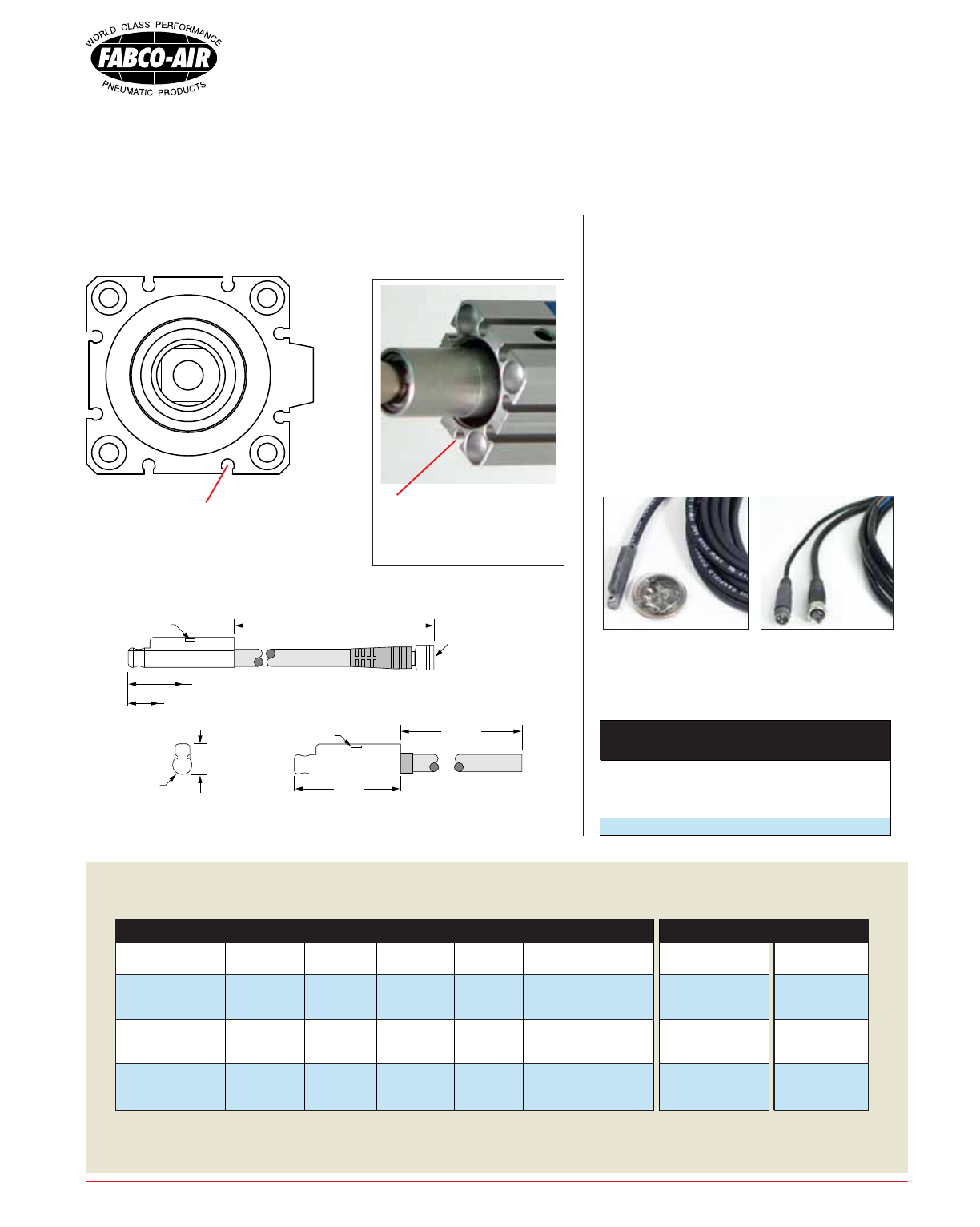
Magnetic Piston is a standard feature of Fabco-Air swing clamp cylinders.
When position sensing is desired for input to signal controllers, Fabco-Air
sensors mount easily and securely inslots on the cylinder body.
7-23-07
4.5 Reed Style
5.8 Electronic Style
LED Indicator
LED Indicator
13.0 to center of Sensing Area for Reed Style
7.0 to center of Sensing Area for Electronic Style
9 ft.
25
6 in. 8mm Male
Quick Connect
ø
3.8
Round Profi le Sensors feature surge sup-
pression, polarity protection, LED indicator,
and extremely fast switching speeds. They
slide into mating 4mm keyhole slots on either
side of the cylinder block and are easily po-
sitioned and locked in place with a set screw.
They are offered in two styles: a quick con-
nect style with a 6 inch pigtail and male con-
nector, or a prewired style with a 9 foot lead.
Female Cordsets are available in 3 pin con-
fi guration in 2 and 5 meter lengths.
Order sensors and cordsets separately
from the tables below.
Sensor Dimensions (mm unless noted)
Cordset
Description
2 meters, 3-Pin
5 meters, 3-Pin
Part No.
CFC-2M
CFC-5M
8mm Female Cordsets
for Quick Connect Sensors
3 pin cordset shown
with sensor pigtail
Prewired sensor shown
with 9 ft. lead
All sensors feature surge supression, polarity protection,
LED indicator, and extremely fast switching speeds.
FABCO-AIR0UJO • 3716 N.E. 49th Avenue • Gainesville, FL 32609 • Tel (352) 373-3578
• Fax (352) 375-8024 • E-Mail: fabco@fabco-air.com • Web Site: www.fabco-air.com
Specifi cations and pricing subject to change without notice or incurring obligation
Magnetically Actuated Sensors –
4mm keyhole slots for
mounting (sensors shown
on ø63 bore – 8 places)
Rod end view showing
4mm keyhole slots on a
ø32 bore clamp cylinder
Magnetic Sensors – Electrical Characteristics Part Numbers
Switching
Speed
0.5 ms operate
0.1 ms release
1.5µs operate
0.5µs release
1.5µs operate
0.5µs release
Switching
Power
4 Watts max.
6 Watts max.
6 Watts max.
Prewired 9 ft.
Part No.
9C49-000-002
9C49-000-031
9C49-000-032
Quick Connect
Part No.
9C49-000-302
Requires 3 pin
cordset
9C49-000-331
Requires 3 pin
cordset
9C49-000-332
Requires 3 pin
cordset
Switching
Voltage
5-120V AC/DC
50/60 Hz
6-30 VDC
6-30 VDC
Switching
Current
0.04 Amp max
0.005 Amp min.
0.2 Amp max.
0.2 Amp max.
Voltage
Drop
2.5 Volts
1.5 Volts
1.5 Volts
Sensor Type
Reed Switch for
PLC’s w/LED
(current limiting)
Electronic
LED and
Sourcing
Electronic
LED and
SInking
Function
SPST
Normally Open
PNP
Normally Open
NPN
Normally Open
