Flow Numatics 502 Series Control Valve 1505491390 User Manual
Numatics 502 Series Control Valve-1505491390 NUMATICS_502_SERIES_CONTROL_VALVE-1505491390
2017-10-06
User Manual: Flow Numatics 502 Series Control Valve-1505491390
Open the PDF directly: View PDF ![]() .
.
Page Count: 32

www.asco.com
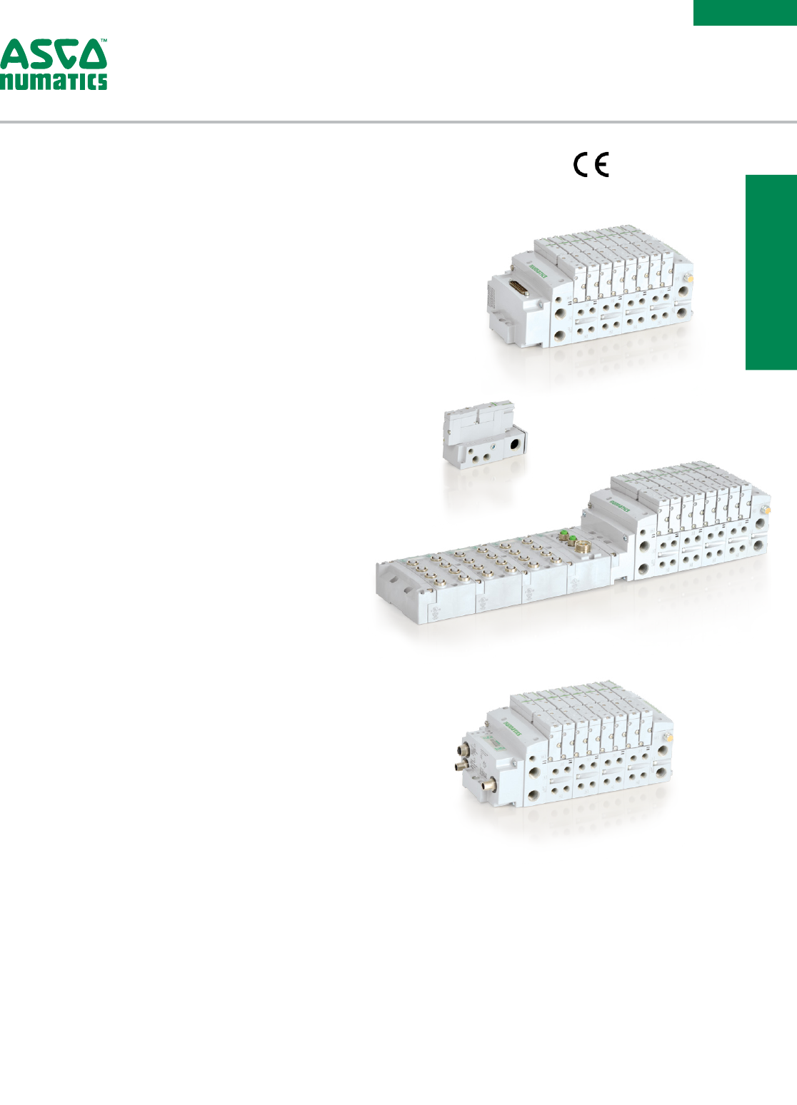
502 Series | Directional Control Valve
Solenoid Pilot Actuated Valves

Table of Contents
502 Series
Features and Benefits 3
Performance Data 4
How to Order 5
Sandwich Option Kit 9
Speed Control Kit 9
Shut Off Block Kit 9
Pressure Block Kit 9
Exhaust Block Kit 9
End Plate Kit 10
Multipin Electrical Interface 11
25 Pin Sub-D Interface 11
37 Pin Sub-D Interface 11
19 Pin M23 Interface 11
26 Pin M27 Interface 11
1-32 Pin Terminal Interface 11
Robot End Effector Interface 11
Accessories Kit 12
Blank Station Plate Kit 12
DIN Rail Clamp Kit 12
Blocking Disc Kit 12
Internal Muffler Kit 12
501 Series Special Fittings 12
Replacement Kit 12
Interface Mounting Kit 12
Regulator Replacement Kit 12
Regulator Gauge Replacement Kit 12
Adaptor Plate Kit 13
Pilot Selection 14
Valve Regulator/Speed Control Plut-In Assembly 14
502 Series Dimensions 15
Adaptor Plate Kit 26
Multipin Electrical Interface 27
Information subject to change without notice. For ordering information or regarding your local sales office visit www.asco.com. 3
SERIES
502
502 PERFORMANCE
& HOW TO ORDER
Fieldbus Electronics Compatible
• G3 Fieldbus Electronics
–Graphic Display for easy commissioning, visual status & diagnostics
–32 valve solenoids per manifold
–Easy distribution of additional manifolds through Sub-Bus
communication
–One Node supports up to 16 I/O modules
–Available with Auto Recovery Module (ARM) which allows
configuration information to be saved and reloaded to replacement
module automatically
• 580 Fieldbus Electronics
–Graphic Display for easy commissioning, visual status & diagnostics
–32 valve solenoids per manifold
Sandwich and Manifold Accessories
• Pressure Regulators for supply pressure control at individual valve
• Speed control to control exhaust flow allows for control of actuator
extend or retract speed
• Shut off block for individual valve to be isolated from pressure supply
during operation and repair
• Mid Station Supply Manifold block allows for multiple pressure zones
(with blocking discs) or additional air supply to a manifold
Features
• Solenoid air pilot actuated
• Low wattage 1.3 Watt for DC application
• DC solenoids Polarity insensitive with surge suppression
• Plug together circuit boards eliminate internal wiring
• Integral recessed gaskets
• IN Fittings to accommodate various tube sizes
• Simple conversion from internal to external pilot
• IP65 Certified
ISO 15407-2/-1
502 Series – Directional Control Valve Platform
Featuring Higher Flow in a Compact Valve Package
Information subject to change without notice. For ordering information or regarding your local sales office visit www.asco.com.
4
SERIES
502
All Solenoids Are Continuous Duty Rated 24 VDC
Power (Watts) 1.3
Holding Current (Amps) 0.054
Ambient Temperature Range Min/Max °F (°C) -14 °F (-10 °C)/122 °F (50 °C)
Operating Data
Materials in Contact w/Fluid
Body Aluminum, E-Coating treatment
Spool Aluminum or Stainless Steel
Piston POM
Spring Steel
Spool Seals NBR + PUR
Other Seals NBR + FKM
Other materials PAM (Polyarylamide)
50% Glass Fiber Reinforced
Valve to Subbase Gasket NBR
Subbases Aluminum, E-Coating treatment
Construction
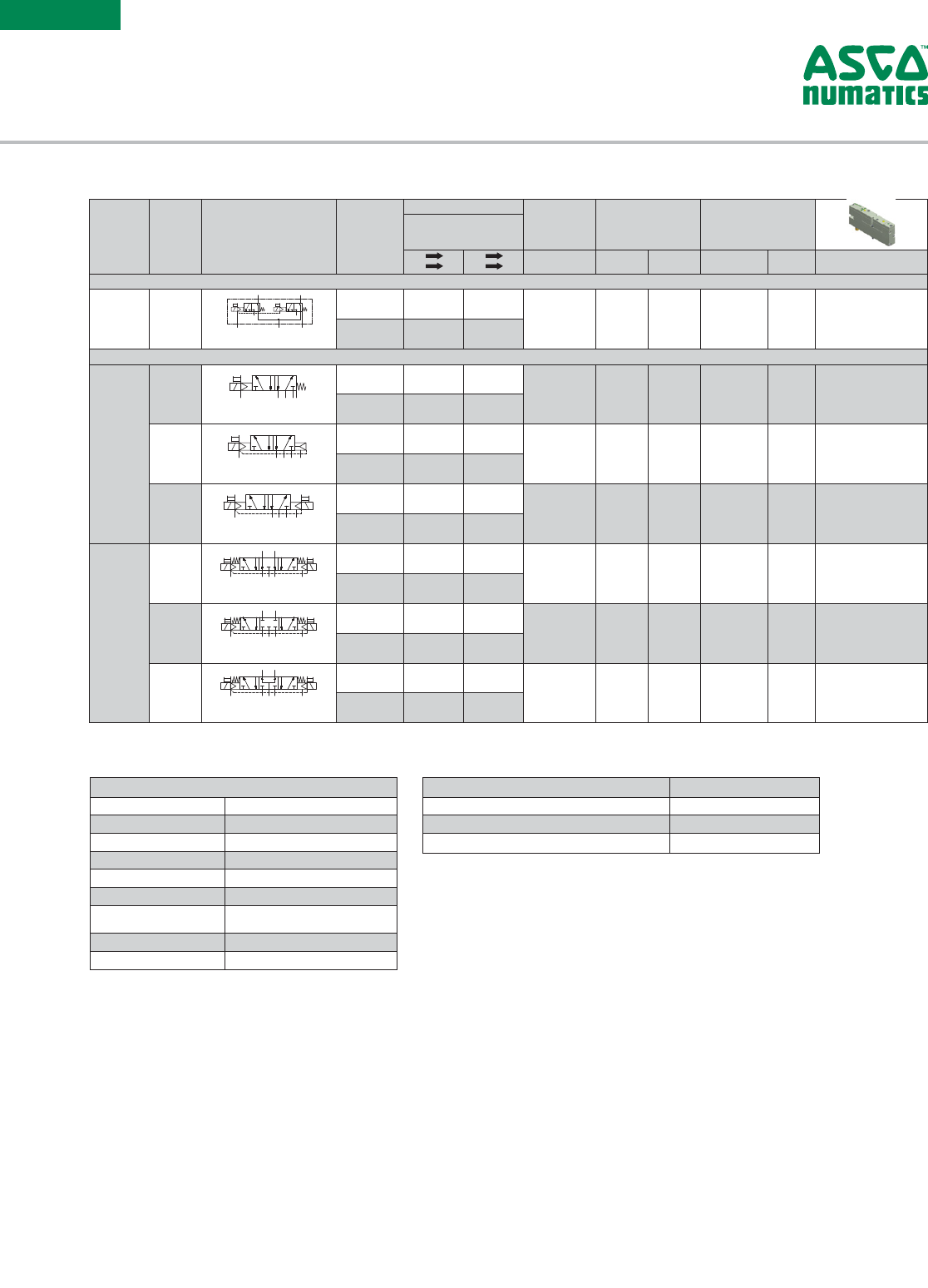
Function
Type
(Function
Code)
Symbol
Pilot (14)
Return (12)
Mounting
Type
Rated Flow Response
Time
(ms)
Pilot Pressure
at 73°F/23°C
PSI (bar)
Operating
Pressure
Port 1 PSI
(bar)/inHg (-bar)
at 90 PSI
Cv
(l/min (ANR))
1 2
1 4
2 3
4 5 Open/Closed min. max min. max Part Number
Rubber Packed Technology, with Manual Override
2 x 3/2
NC BD
1
(A)
14 83
(12)
1
4 2
35
14 83
(12)
1
4 2
3
5
14
83
(12)
1
4 2
35
14
83
(12)
1
4 2
35
5/2 PNEUMATIC SYMBOLS
83
(12)
004A1
004A3
004A5
004A6
004A8
004A10
004F1
004F3
004F5
004F6
004F8
004F10
14 1
42
351
42
35 83
(12)
14 12
14 1
4 2
351
4 2
35
1214
004A14 004F14
004A15 004F15
SYMBOLES PNEUMATIQUES DISTRIBUTEUR 5/2 - VERSION METAL METAL
5/2 PNEUMATIC SYMBOLS - SPOOL AND SLEEVE VERSION
1
4 2
35
14 1
4 2
35
14
1
4 2
3
5
14 1
4 2
3
5
14
1
4 2
35
14 1
4 2
35
14
1
4 2
35
14 1
4 2
35
1
4 2
35
14 1
4 2
35
1
4 2
35
14 1
4 2
35
14
14
14
005A1 005F1
005A2 005F2
005A3 005F3
005A4 005F4
005A5 005F5
005A6 005F6
5
4
5
3
3
2
5
3
3
5
14 12
14 10
10 10
10 12
5
5
3
3
5
3
3
5
14 12
14 10
10 10
10 12
10 10 10 10
10 12 10 12
14 12 14 12
14 10 14 10
5
5
3
3
5
3
3
5
14 12
14 10
10 10
10 12
5
5
3
3
5
3
3
5
14 12
14 10
10 10
10 12
10 10 10 10
10 12 10 12
14 12 14 12
14 10 14 10
1
006A9 006F9
006A10 006F10
006A11 006F11
006A12 006F12
006A13 006F13
006A14 006F14
006A15 006F15
006A16 006F16
1
1
1
1
1
1
1
1
1
1
1
1
1
1
1
83
(12)
4 2
42
4 2
4 2
4 2
4 2
4 2
4 2
4 2
4 2
4 2
4 2
4 2
4 2
4 2
SYMBOLES PNEUMATIQUES DISTRIBUTEUR 5/3
5/3 PNEUMATIC SYMBOLS
SYMBOLES PNEUMATIQUES DISTRIBUTEUR 2X 3/2
2X 3/2 PNEUMATIC SYMBOLS
83
(12)
14
14
14
14
14
14
14
14
83
(12)
83
(12)
83
(12)
83
(12)
83
(12)
83
(12)
83
(12)
83
(12)
83
(12)
83
(12)
83
(12)
83
(12)
83
(12)
83
(12)
83
(12)
83
(12)
83
(12)
83
(12)
83
(12)
83
(12)
83
(12)
83
(12)
83
(12)
83
(12)
83
(12)
83
(12)
83
(12)
83
(12)
83
(12)
83
(12)
83
(12)
83
(12)
83
(12)
83
(12)
83
(12)
83
(12)
83
(12)
83
(12)
83
(12)
83
(12)
005A7 005F7
005A8 005F8
SYMBOLES PNEUMATIQUES DISTRIBUTEUR 5/3 W2 - VERSION METAL METAL
5/3 W2 PNEUMATIC SYMBOLS - SPOOL AND SLEEVE VERSION
4 2
35 1
4 2
35
14
14 1
4 2
35
12
1
4 2
35
14 1
4 2
351
4 2
35
14
14
14
1
4 2
35 1
4 2
35
14
14 1
4 2
35
12
1
4 2
35
14 1
4 2
351
4 2
35
14
14
14
SYMBOLES PNEUMATIQUES DISTRIBUTEUR 5/2
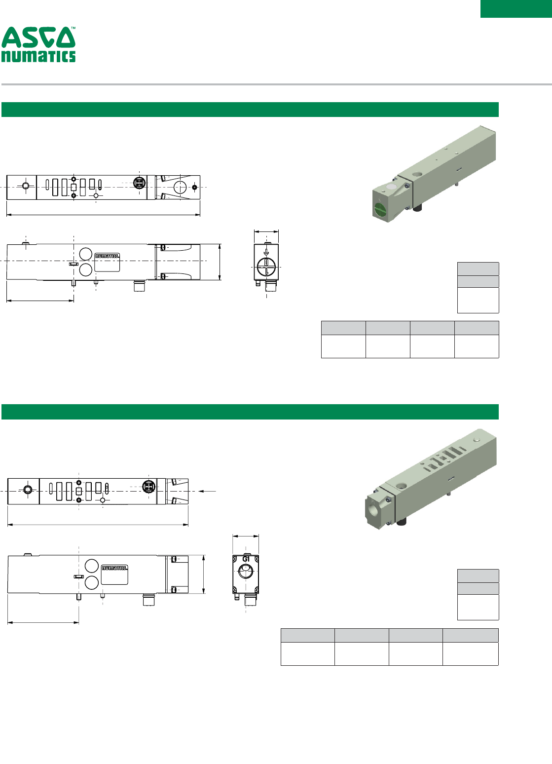
Normally Closed
Proprietary 0.650
(650)
0.600
(600)
36/15 58
(4.0)
115
(8)
36
(2)
115
(8) R502A2BD0MA00F1
ISO 0.500
(500)
0.440
(440)
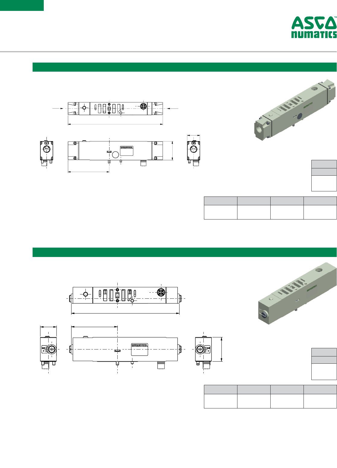
Spool and Sleeve Technology, with Manual Override
5/2
B1
1
(A)
14 83
(12)
1
4 2
35
14 83
(12)
1
4 2
3
5
14
83
(12)
1
4 2
35
14
83
(12)
1
4 2
35
5/2 PNEUMATIC SYMBOLS
83
(12)
004A1
004A3
004A5
004A6
004A8
004A10
004F1
004F3
004F5
004F6
004F8
004F10
14 1
42
351
42
35 83
(12)
14 12
14 1
4 2
351
4 2
35
1214
004A14 004F14
004A15 004F15
SYMBOLES PNEUMATIQUES DISTRIBUTEUR 5/2 - VERSION METAL METAL
5/2 PNEUMATIC SYMBOLS - SPOOL AND SLEEVE VERSION
1
4 2
35
14 1
4 2
35
14
1
4 2
3
5
14 1
4 2
3
5
14
1
4 2
35
14 1
4 2
35
14
1
4 2
35
14 1
4 2
35
1
4 2
35
14 1
4 2
35
1
4 2
35
14 1
4 2
35
14
14
14
005A1 005F1
005A2 005F2
005A3 005F3
005A4 005F4
005A5 005F5
005A6 005F6
5
4
5
3
3
2
5
3
3
5
14 12
14 10
10 10
10 12
5
5
3
3
5
3
3
5
14 12
14 10
10 10
10 12
10 10 10 10
10 12 10 12
14 12 14 12
14 10 14 10
5
5
3
3
5
3
3
5
14 12
14 10
10 10
10 12
5
5
3
3
5
3
3
5
14 12
14 10
10 10
10 12
10 10 10 10
10 12 10 12
14 12 14 12
14 10 14 10
1
006A9 006F9
006A10 006F10
006A11 006F11
006A12 006F12
006A13 006F13
006A14 006F14
006A15 006F15
006A16 006F16
1
1
1
1
1
1
1
1
1
1
1
1
1
1
1
83
(12)
4 2
4 2
4 2
4 2
4 2
4 2
4 2
4 2
4 2
4 2
4 2
4 2
4 2
4 2
4 2
SYMBOLES PNEUMATIQUES DISTRIBUTEUR 5/3
5/3 PNEUMATIC SYMBOLS
SYMBOLES PNEUMATIQUES DISTRIBUTEUR 2X 3/2
2X 3/2 PNEUMATIC SYMBOLS
83
(12)
14
14
14
14
14
14
14
14
83
(12)
83
(12)
83
(12)
83
(12)
83
(12)
83
(12)
83
(12)
83
(12)
83
(12)
83
(12)
83
(12)
83
(12)
83
(12)
83
(12)
83
(12)
83
(12)
83
(12)
83
(12)
83
(12)
83
(12)
83
(12)
83
(12)
83
(12)
83
(12)
83
(12)
83
(12)
83
(12)
83
(12)
83
(12)
83
(12)
83
(12)
83
(12)
83
(12)
83
(12)
83
(12)
83
(12)
83
(12)
83
(12)
83
(12)
83
(12)
005A7 005F7
005A8 005F8
SYMBOLES PNEUMATIQUES DISTRIBUTEUR 5/3 W2 - VERSION METAL METAL
5/3 W2 PNEUMATIC SYMBOLS - SPOOL AND SLEEVE VERSION
4 2
35 1
4 2
35
14
14 1
4 2
35
12
1
4 2
35
14 1
4 2
351
4 2
35
14
14
14
1
4 2
35 1
4 2
35
14
14 1
4 2
35
12
1
4 2
35
14 1
4 2
351
4 2
35
14
14
14
SYMBOLES PNEUMATIQUES DISTRIBUTEUR 5/2
Spring Return
Proprietary 0.470
(470)
0.530
(530)
16/49 29
(2)
115
(8)
28
(-0.95)
115
(8) R502A1B10MA00F1
ISO 0.410
(410)
0.390
(390)
BN
1
(A)
14 83
(12)
1
4 2
35
14 83
(12)
1
4 2
3
5
14
83
(12)
1
4 2
35
14
83
(12)
1
4 2
35
5/2 PNEUMATIC SYMBOLS
83
(12)
004A1
004A3
004A5
004A6
004A8
004A10
004F1
004F3
004F5
004F6
004F8
004F10
14 1
42
351
42
35 83
(12)
14 12
14 1
4 2
351
4 2
35
1214
004A14 004F14
004A15 004F15
SYMBOLES PNEUMATIQUES DISTRIBUTEUR 5/2 - VERSION METAL METAL
5/2 PNEUMATIC SYMBOLS - SPOOL AND SLEEVE VERSION
1
4 2
35
14 1
4 2
35
14
1
4 2
3
5
14 1
4 2
3
5
14
1
4 2
35
14 1
4 2
35
14
1
4 2
35
14 1
4 2
35
1
4 2
35
14 1
4 2
35
1
4 2
35
14 1
4 2
35
14
14
14
005A1 005F1
005A2 005F2
005A3 005F3
005A4 005F4
005A5 005F5
005A6 005F6
5
4
5
3
3
2
5
3
3
5
14 12
14 10
10 10
10 12
5
5
3
3
5
3
3
5
14 12
14 10
10 10
10 12
10 10 10 10
10 12 10 12
14 12 14 12
14 10 14 10
5
5
3
3
5
3
3
5
14 12
14 10
10 10
10 12
5
5
3
3
5
3
3
5
14 12
14 10
10 10
10 12
10 10 10 10
10 12 10 12
14 12 14 12
14 10 14 10
1
006A9 006F9
006A10 006F10
006A11 006F11
006A12 006F12
006A13 006F13
006A14 006F14
006A15 006F15
006A16 006F16
1
1
1
1
1
1
1
1
1
1
1
1
1
1
1
83
(12)
4 2
4 2
4 2
4 2
4 2
4 2
4 2
4 2
4 2
4 2
4 2
4 2
4 2
4 2
4 2
SYMBOLES PNEUMATIQUES DISTRIBUTEUR 5/3
5/3 PNEUMATIC SYMBOLS
SYMBOLES PNEUMATIQUES DISTRIBUTEUR 2X 3/2
2X 3/2 PNEUMATIC SYMBOLS
83
(12)
14
14
14
14
14
14
14
14
83
(12)
83
(12)
83
(12)
83
(12)
83
(12)
83
(12)
83
(12)
83
(12)
83
(12)
83
(12)
83
(12)
83
(12)
83
(12)
83
(12)
83
(12)
83
(12)
83
(12)
83
(12)
83
(12)
83
(12)
83
(12)
83
(12)
83
(12)
83
(12)
83
(12)
83
(12)
83
(12)
83
(12)
83
(12)
83
(12)
83
(12)
83
(12)
83
(12)
83
(12)
83
(12)
83
(12)
83
(12)
83
(12)
83
(12)
83
(12)
005A7 005F7
005A8 005F8
SYMBOLES PNEUMATIQUES DISTRIBUTEUR 5/3 W2 - VERSION METAL METAL
5/3 W2 PNEUMATIC SYMBOLS - SPOOL AND SLEEVE VERSION
4 2
35 1
4 2
35
14
14 1
4 2
35
12
1
4 2
35
14 1
4 2
351
4 2
35
14
14
14
1
4 2
35 1
4 2
35
14
14 1
4 2
35
12
1
4 2
35
14 1
4 2
351
4 2
35
14
14
14
SYMBOLES PNEUMATIQUES DISTRIBUTEUR 5/2
Differential Air Return
Proprietary 0.470
(470)
0.530
(530)
11/2 6 22
(1.5)
115
(8)
28
(-0.95)
115
(8) R502A1BN0MA00F1
ISO 0.410
(410)
0.390
(390)
B4
1
(A)
14 83
(12)
1
4 2
35
14 83
(12)
1
4 2
3
5
14
83
(12)
1
4 2
35
14
83
(12)
1
4 2
35
5/2 PNEUMATIC SYMBOLS
83
(12)
004A1
004A3
004A5
004A6
004A8
004A10
004F1
004F3
004F5
004F6
004F8
004F10
14 1
42
351
42
35 83
(12)
14 12
14 1
4 2
351
4 2
35
1214
004A14 004F14
004A15 004F15
SYMBOLES PNEUMATIQUES DISTRIBUTEUR 5/2 - VERSION METAL METAL
5/2 PNEUMATIC SYMBOLS - SPOOL AND SLEEVE VERSION
1
4 2
35
14 1
4 2
35
14
1
4 2
3
5
14 1
4 2
3
5
14
1
4 2
35
14 1
4 2
35
14
1
4 2
35
14 1
4 2
35
1
4 2
35
14 1
4 2
35
1
4 2
35
14 1
4 2
35
14
14
14
005A1 005F1
005A2 005F2
005A3 005F3
005A4 005F4
005A5 005F5
005A6 005F6
5
4
5
3
3
2
5
3
3
5
14 12
14 10
10 10
10 12
5
5
3
3
5
3
3
5
14 12
14 10
10 10
10 12
10 10 10 10
10 12 10 12
14 12 14 12
14 10 14 10
5
5
3
3
5
3
3
5
14 12
14 10
10 10
10 12
5
5
3
3
5
3
3
5
14 12
14 10
10 10
10 12
10 10 10 10
10 12 10 12
14 12 14 12
14 10 14 10
1
006A9 006F9
006A10 006F10
006A11 006F11
006A12 006F12
006A13 006F13
006A14 006F14
006A15 006F15
006A16 006F16
1
1
1
1
1
1
1
1
1
1
1
1
1
1
1
83
(12)
4 2
4 2
4 2
4 2
4 2
4 2
4 2
4 2
4 2
4 2
4 2
4 2
4 2
4 2
4 2
SYMBOLES PNEUMATIQUES DISTRIBUTEUR 5/3
5/3 PNEUMATIC SYMBOLS
SYMBOLES PNEUMATIQUES DISTRIBUTEUR 2X 3/2
2X 3/2 PNEUMATIC SYMBOLS
83
(12)
14
14
14
14
14
14
14
14
83
(12)
83
(12)
83
(12)
83
(12)
83
(12)
83
(12)
83
(12)
83
(12)
83
(12)
83
(12)
83
(12)
83
(12)
83
(12)
83
(12)
83
(12)
83
(12)
83
(12)
83
(12)
83
(12)
83
(12)
83
(12)
83
(12)
83
(12)
83
(12)
83
(12)
83
(12)
83
(12)
83
(12)
83
(12)
83
(12)
83
(12)
83
(12)
83
(12)
83
(12)
83
(12)
83
(12)
83
(12)
83
(12)
83
(12)
83
(12)
005A7 005F7
005A8 005F8
SYMBOLES PNEUMATIQUES DISTRIBUTEUR 5/3 W2 - VERSION METAL METAL
5/3 W2 PNEUMATIC SYMBOLS - SPOOL AND SLEEVE VERSION
4 2
35 1
4 2
35
14
14 1
4 2
35
12
1
4 2
35
14 1
4 2
35
1
4 2
35
14
14
14
1
4 2
35 1
4 2
35
14
14 1
4 2
35
12
1
4 2
35
14 1
4 2
351
4 2
35
14
14
14
SYMBOLES PNEUMATIQUES DISTRIBUTEUR 5/2
Solenoid Air Return
Proprietary 0.470
(470)
0.530
(530)
12/15 29
(2)
115
(8)
28
(-0.95)
115
(8) R502A1B50MA00F1
ISO 0.410
(410)
0.390
(390)
5/3
B5
1
(A)
14 83
(12)
1
4 2
35
14 83
(12)
1
4 2
3
5
14
83
(12)
1
4 2
35
14
83
(12)
1
4 2
35
5/2 PNEUMATIC SYMBOLS
83
(12)
004A1
004A3
004A5
004A6
004A8
004A10
004F1
004F3
004F5
004F6
004F8
004F10
14 1
42
351
42
35 83
(12)
14 12
14 1
4 2
351
4 2
35
1214
004A14 004F14
004A15 004F15
SYMBOLES PNEUMATIQUES DISTRIBUTEUR 5/2 - VERSION METAL METAL
5/2 PNEUMATIC SYMBOLS - SPOOL AND SLEEVE VERSION
1
4 2
35
14 1
4 2
35
14
1
4 2
3
5
14 1
4 2
3
5
14
1
4 2
35
14 1
4 2
35
14
1
4 2
35
14 1
4 2
35
1
4 2
35
14 1
4 2
35
1
4 2
35
14 1
4 2
35
14
14
14
005A1 005F1
005A2 005F2
005A3 005F3
005A4 005F4
005A5 005F5
005A6 005F6
5
4
5
3
3
2
5
3
3
5
14 12
14 10
10 10
10 12
5
5
3
3
5
3
3
5
14 12
14 10
10 10
10 12
10 10 10 10
10 12 10 12
14 12 14 12
14 10 14 10
5
5
3
3
5
3
3
5
14 12
14 10
10 10
10 12
5
5
3
3
5
3
3
5
14 12
14 10
10 10
10 12
10 10 10 10
10 12 10 12
14 12 14 12
14 10 14 10
1
006A9 006F9
006A10 006F10
006A11 006F11
006A12 006F12
006A13 006F13
006A14 006F14
006A15 006F15
006A16 006F16
1
1
1
1
1
1
1
1
1
1
1
1
1
1
1
83
(12)
4 2
4 2
4 2
4 2
4 2
4 2
4 2
4 2
4 2
4 2
4 2
4 2
4 2
4 2
4 2
SYMBOLES PNEUMATIQUES DISTRIBUTEUR 5/3
5/3 PNEUMATIC SYMBOLS
SYMBOLES PNEUMATIQUES DISTRIBUTEUR 2X 3/2
2X 3/2 PNEUMATIC SYMBOLS
83
(12)
14
14
14
14
14
14
14
14
83
(12)
83
(12)
83
(12)
83
(12)
83
(12)
83
(12)
83
(12)
83
(12)
83
(12)
83
(12)
83
(12)
83
(12)
83
(12)
83
(12)
83
(12)
83
(12)
83
(12)
83
(12)
83
(12)
83
(12)
83
(12)
83
(12)
83
(12)
83
(12)
83
(12)
83
(12)
83
(12)
83
(12)
83
(12)
83
(12)
83
(12)
83
(12)
83
(12)
83
(12)
83
(12)
83
(12)
83
(12)
83
(12)
83
(12)
83
(12)
005A7 005F7
005A8 005F8
SYMBOLES PNEUMATIQUES DISTRIBUTEUR 5/3 W2 - VERSION METAL METAL
5/3 W2 PNEUMATIC SYMBOLS - SPOOL AND SLEEVE VERSION
4 2
35 1
4 2
35
14
14 1
4 2
35
12
1
4 2
35
14 1
4 2
351
4 2
35
14
14
14
1
4 2
35 1
4 2
35
14
14 1
4 2
35
12
1
4 2
35
14 1
4 2
351
4 2
35
14
14
14
SYMBOLES PNEUMATIQUES DISTRIBUTEUR 5/2
Center Open to Exhaust
Proprietary 0.380
(380)
0.500
(500)
23/13 22
(1.5)
115
(8)
28
(-0.95)
115
(8) R502A1B50MA00F1
ISO 0.340
(340)
0.350
(350)
B6
1
(A)
14 83
(12)
1
4 2
35
14 83
(12)
1
4 2
3
5
14
83
(12)
1
4 2
35
14
83
(12)
1
4 2
35
5/2 PNEUMATIC SYMBOLS
83
(12)
004A1
004A3
004A5
004A6
004A8
004A10
004F1
004F3
004F5
004F6
004F8
004F10
14 1
42
351
42
35 83
(12)
14 12
14 1
4 2
351
4 2
35
1214
004A14 004F14
004A15 004F15
SYMBOLES PNEUMATIQUES DISTRIBUTEUR 5/2 - VERSION METAL METAL
5/2 PNEUMATIC SYMBOLS - SPOOL AND SLEEVE VERSION
1
4 2
35
14 1
4 2
35
14
1
4 2
3
5
14 1
4 2
3
5
14
1
4 2
35
14 1
4 2
35
14
1
4 2
35
14 1
4 2
35
1
4 2
35
14 1
4 2
35
1
4 2
35
14 1
4 2
35
14
14
14
005A1 005F1
005A2 005F2
005A3 005F3
005A4 005F4
005A5 005F5
005A6 005F6
5
4
5
3
3
2
5
3
3
5
14 12
14 10
10 10
10 12
5
5
3
3
5
3
3
5
14 12
14 10
10 10
10 12
10 10 10 10
10 12 10 12
14 12 14 12
14 10 14 10
5
5
3
3
5
3
3
5
14 12
14 10
10 10
10 12
5
5
3
3
5
3
3
5
14 12
14 10
10 10
10 12
10 10 10 10
10 12 10 12
14 12 14 12
14 10 14 10
1
006A9 006F9
006A10 006F10
006A11 006F11
006A12 006F12
006A13 006F13
006A14 006F14
006A15 006F15
006A16 006F16
1
1
1
1
1
1
1
1
1
1
1
1
1
1
1
83
(12)
4 2
4 2
4 2
4 2
4 2
4 2
4 2
4 2
4 2
4 2
4 2
4 2
4 2
4 2
4 2
SYMBOLES PNEUMATIQUES DISTRIBUTEUR 5/3
5/3 PNEUMATIC SYMBOLS
SYMBOLES PNEUMATIQUES DISTRIBUTEUR 2X 3/2
2X 3/2 PNEUMATIC SYMBOLS
83
(12)
14
14
14
14
14
14
14
14
83
(12)
83
(12)
83
(12)
83
(12)
83
(12)
83
(12)
83
(12)
83
(12)
83
(12)
83
(12)
83
(12)
83
(12)
83
(12)
83
(12)
83
(12)
83
(12)
83
(12)
83
(12)
83
(12)
83
(12)
83
(12)
83
(12)
83
(12)
83
(12)
83
(12)
83
(12)
83
(12)
83
(12)
83
(12)
83
(12)
83
(12)
83
(12)
83
(12)
83
(12)
83
(12)
83
(12)
83
(12)
83
(12)
83
(12)
83
(12)
005A7 005F7
005A8 005F8
SYMBOLES PNEUMATIQUES DISTRIBUTEUR 5/3 W2 - VERSION METAL METAL
5/3 W2 PNEUMATIC SYMBOLS - SPOOL AND SLEEVE VERSION
4 2
35 1
4 2
35
14
14 1
4 2
35
12
1
4 2
35
14 1
4 2
351
4 2
35
14
14
14
1
4 2
35 1
4 2
35
14
14 1
4 2
35
12
1
4 2
35
14 1
4 2
351
4 2
35
14
14
14
SYMBOLES PNEUMATIQUES DISTRIBUTEUR 5/2
Center Closed
Proprietary 0.420
(420)
0.440
(440)
12/12 22
(1.5)
115
(8)
28
(-0.95)
115
(8) R502A1B60MA00F1
ISO 0.360
(360)
0.350
(350)
B7
1
(A)
14 83
(12)
1
4 2
35
14 83
(12)
1
4 2
3
5
14
83
(12)
1
4 2
35
14
83
(12)
1
4 2
35
5/2 PNEUMATIC SYMBOLS
83
(12)
004A1
004A3
004A5
004A6
004A8
004A10
004F1
004F3
004F5
004F6
004F8
004F10
14 1
42
351
42
35 83
(12)
14 12
14 1
4 2
351
4 2
35
1214
004A14 004F14
004A15 004F15
SYMBOLES PNEUMATIQUES DISTRIBUTEUR 5/2 - VERSION METAL METAL
5/2 PNEUMATIC SYMBOLS - SPOOL AND SLEEVE VERSION
1
4 2
35
14 1
4 2
35
14
1
4 2
3
5
14 1
4 2
3
5
14
1
4 2
35
14 1
4 2
35
14
1
4 2
35
14 1
4 2
35
1
4 2
35
14 1
4 2
35
1
4 2
35
14 1
4 2
35
14
14
14
005A1 005F1
005A2 005F2
005A3 005F3
005A4 005F4
005A5 005F5
005A6 005F6
5
4
5
3
3
2
5
3
3
5
14 12
14 10
10 10
10 12
5
5
3
3
5
3
3
5
14 12
14 10
10 10
10 12
10 10 10 10
10 12 10 12
14 12 14 12
14 10 14 10
5
5
3
3
5
3
3
5
14 12
14 10
10 10
10 12
5
5
3
3
5
3
3
5
14 12
14 10
10 10
10 12
10 10 10 10
10 12 10 12
14 12 14 12
14 10 14 10
1
006A9 006F9
006A10 006F10
006A11 006F11
006A12 006F12
006A13 006F13
006A14 006F14
006A15 006F15
006A16 006F16
1
1
1
1
1
1
1
1
1
1
1
1
1
1
1
83
(12)
4 2
4 2
4 2
4 2
4 2
4 2
4 2
4 2
4 2
4 2
4 2
4 2
4 2
4 2
4 2
SYMBOLES PNEUMATIQUES DISTRIBUTEUR 5/3
5/3 PNEUMATIC SYMBOLS
SYMBOLES PNEUMATIQUES DISTRIBUTEUR 2X 3/2
2X 3/2 PNEUMATIC SYMBOLS
83
(12)
14
14
14
14
14
14
14
14
83
(12)
83
(12)
83
(12)
83
(12)
83
(12)
83
(12)
83
(12)
83
(12)
83
(12)
83
(12)
83
(12)
83
(12)
83
(12)
83
(12)
83
(12)
83
(12)
83
(12)
83
(12)
83
(12)
83
(12)
83
(12)
83
(12)
83
(12)
83
(12)
83
(12)
83
(12)
83
(12)
83
(12)
83
(12)
83
(12)
83
(12)
83
(12)
83
(12)
83
(12)
83
(12)
83
(12)
83
(12)
83
(12)
83
(12)
83
(12)
005A7 005F7
005A8 005F8
SYMBOLES PNEUMATIQUES DISTRIBUTEUR 5/3 W2 - VERSION METAL METAL
5/3 W2 PNEUMATIC SYMBOLS - SPOOL AND SLEEVE VERSION
4 2
35 1
4 2
35
14
14 1
4 2
35
12
1
4 2
35
14 1
4 2
351
4 2
35
14
14
14
1
4 2
35 1
4 2
35
14
14 1
4 2
35
12
1
4 2
35
14 1
4 2
35
1
4 2
35
14
14
14
SYMBOLES PNEUMATIQUES DISTRIBUTEUR 5/2
Center Open to Pressure
Proprietary 0.420
(420)
0.430
(430)
13/23 22
(1.5)
115
(8)
28
(-0.95)
115
(8) R502A1B70MA00F1
ISO 0.370
(370)
0.350
(350)
Performance Data
Information subject to change without notice. For ordering information or regarding your local sales office visit www.asco.com. 5
SERIES
502
1 Available with Function D only
2 See diagram:
4 3
21
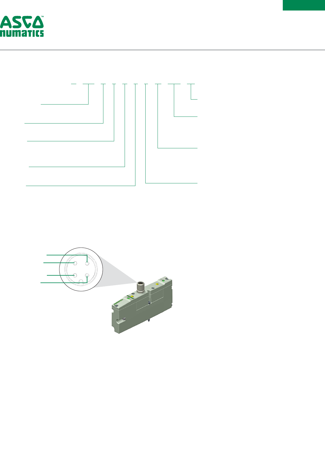
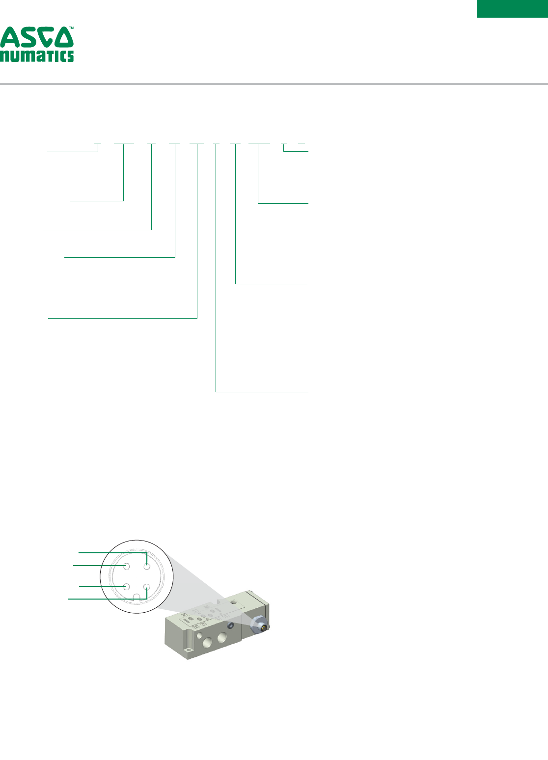
Pin 3 = Common
Pin 4 = Coil 14
Pin 1 = Not Used
Pin 2 = Coil 12
Port Size
0 = No Port Size
Electrical
M = Plug-in, w/Light, VDC
N = M12 Connector
Pin 1 = Not Used; Pin 2 = Coil 12;
Pin 3 = Common; Pin 4 = Coil 14
Options
A00 = Standard (No Options)
11B = Flush Locking Manual Override
11M = Without Manual Override
Voltage
F1 = 24 DC
Function
1 = 2 Position 4-Way (5/2), Spring Return
4 = 2 Position 4-Way (5/2), Dual Solenoid
5 = 3 Position 4-Way (5/3), Open Center, Dual Pressure
6 = 3 Position 4-Way (5/3), Blocked Center
D = Dual 3-way, 2 Normally Closed - 4 Normally Closed
Valve Type
B = Solenoid Pilot with Flush Non-Locking Override
2
1
Actuation
1 = Spool and Sleeve
2 = Rubber Packed
Revision
A = Initial Release
Product Series
502 = 18mm Valve
R 502 A 2 B 4 0 M A00 F1
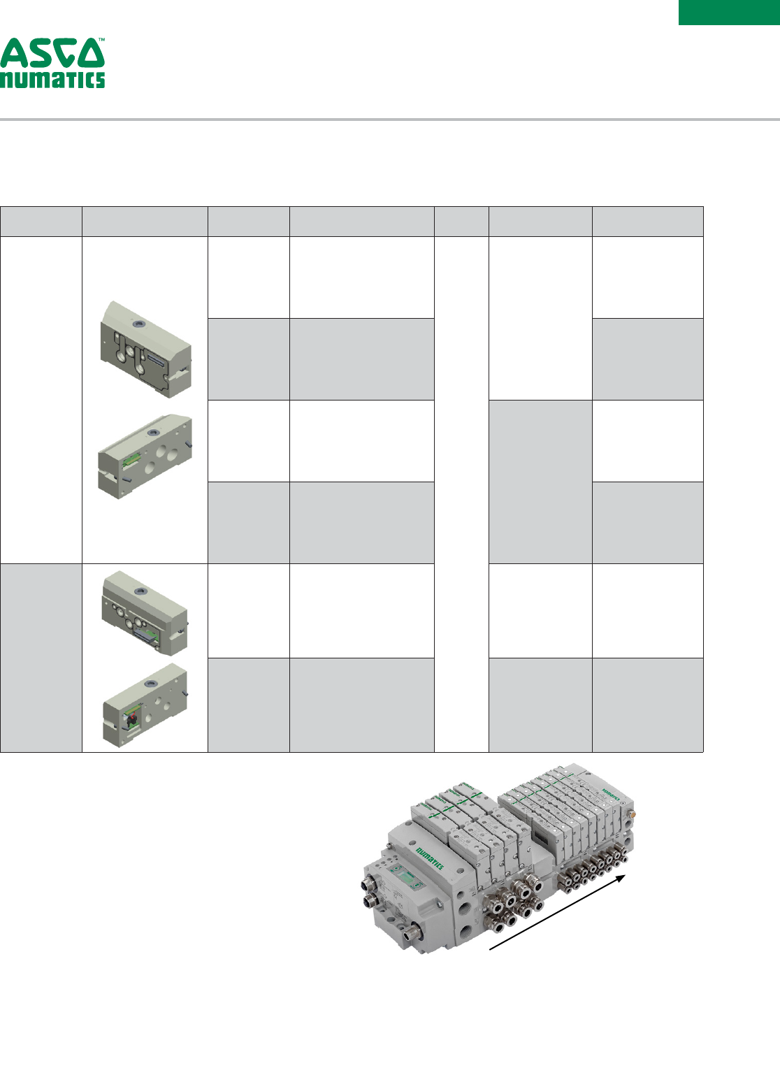
How to Order
Valve
Information subject to change without notice. For ordering information or regarding your local sales office visit www.asco.com.
6
SERIES
502
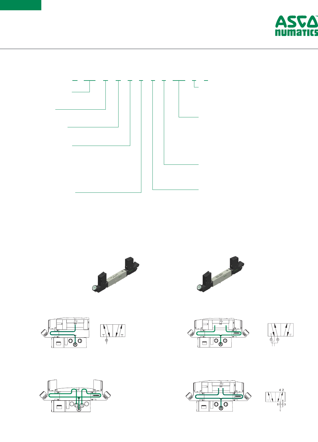
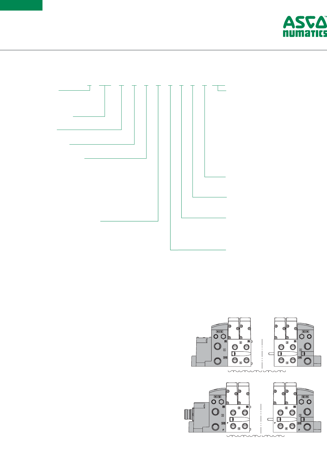
Type RS Type RD
5
1
3
24
42
53
1
Type RE Type RT
3
1
1
SUPPLY
Two-pressure selector used for multi-pressure
applications.
24 35
1
SUPPLY
External outlet regulator used with jumper plate
for single or dual pressure.
5 3
1
SUPPLY
Dual pressure from a single supply.
2
1
SUPPLY
Single pressure from a single supply.
Proprietary InterfaceISO 15407-2/15407-1 Inter face
Sandwich Pressure Regulator Block
Types: RS / RD / RE / RT
Gauge Type
1 = PSI
2 = bar
8 = with NPTF adaptor for external gauge
G = with G tap adaptor for external gauge
Wiring Option
J = Plug-in, Receptacle Assembly
0 = Non Plug-in
Options
A00 = Standard (No Options)
14M = Temperproof Needle Cartridge Assembly or
Regulator
16N = Jumper for Supply Pressure to Valve, 14 End
16P = Jumper for Supply Pressure to Valve, 12 End
61Y = Regulator with Gauge Extension Fitting
Interface
1 = Proprietary
2 = ISO 15407-2
3 = ISO 15407-1
Pressure Range
1 = 10 - 130 PSIG (0.7 - 9 bar)
3 = 3 - 30 PSIG (0.2 - 2 bar)
4 = 5 - 60 PSIG (0.3 - 4.1 bar)
Regulator Type
S = Single Reg. - Pressure to Port 1
D = Double Reg. - Pressure to Ports 5 & 3
E = Double Reg. - Pressure to Ports 4 & 2,
w/o Valve
T = Double Reg. - Pressure to Ports 1 & 3,
2 Pressure Selector
Product Type
R = Regulator
Revision
A = Initial Release
Product Series
502 = 18mm Valve
R 502 A R S 1 1 J A00 1 0
How to Order
Regulator
* Regulator gauges must be offset with 61Y option on alternating stations to prevent interference.
*
Information subject to change without notice. For ordering information or regarding your local sales office visit www.asco.com. 7
SERIES
502
Port Size
1 = 1/8
2 = 1/4 (Push-in Fittings Only)
G = 5/16 (Push-in Fittings Only)
F = 6mm (Push-in Fittings Only)
H = 8mm (Push-in Fittings Only)
7
5
4
Wiring Option
M = Plug-in, Receptacle Assembly
0 = Non Plug-in
Y = Additional Valve Driver
Z = Additional Valve Driver with Auxiliary
Power
V = +24 VDC Separation at First Station
W = +24 VDC Separation at Second Station
T = 32+ Coil Auxiliary Power with X16 Drivers
6
6 & 8
Options
A00 = Standard (No Options)
14X = External Pilot Supply from Port # 14
56Y = 4-Pin Straight M12 Connector in
Mounting Pin 1 = Not Used;
Pin 2 = 12+ (B+); Pin 3 = COM;
Pin 4 = 14+ (A+)
Interface
1 = Proprietary
2 = ISO 15407-2
3 = ISO 15407-1
5
2
4
Mounting
S2 = Manifold Subbase, 2 Stations, Side Ports,
Single Z-Board
M2 = Manifold Subbase, 2 Stations, Side Ports,
Double Z-Board
V2 = Manifold Subbase, 2 Stations, Side Ports
3A = Individual Subbase, Side Ports, Individual
Exhaust
M4 = 32+ Coil Manifold Subbase, 4 Stations, Side
Ports, Double Z-Board
2
3
4
Product Series
502 = 18mm Valve
Revision
A = Initial Release
Product Type
M = Manifold Subbase
A = Individual Subbase
Z = Mid Station Supply
F = 32+ Coil Manifold Subbase
1
1
Port Type
8 = NPTF
G = ISO228/1-G
K = Push-in Fittings
8 502 A M S2 1 M A00 1 0
How to Order
Manifold Block and Individual Subbase
RULE:
32+ Coil Rule: Product Type F, Mounting M4, and Wiring Option T must all be selected together
1 Port Type 8 & G available in 1/8 size for Product Type M and Z or 1/4 for Product Type A
2 Not available with proprietary interface
3 Only available with M2 and V2 mountings
4 32+ Coil Rule: Product Type F, Mounting M4, and Wiring Option T must all be selected together
5 Only available with ISO 15407-1 Interface
6 Available with 3A mounting only
7 Not available with V2 Mounting
8 See diagram:
4 3
21
Pin 3 = Common
Pin 4 = Coil 14
Pin 1 = Not Used
Pin 2 = Coil 12
Information subject to change without notice. For ordering information or regarding your local sales office visit www.asco.com.
8
SERIES
502
VALVE
STATIONS 12 22/32
....
12 22/32
....
VALVE
STATIONS
NOTE: Example order for Fieldbus electronics see 580 or G3 Fieldbus catalog.
Example Order - 502 Shown
25 Pin Sub-D 8502AVJF300VA00
Valve Station #1 R502A2B40MA00F1
Valve Station #2 R502A2B40MA00F1
Mounting #1 8502AMM21MA0010
Valve Station #3 R502A2B60MA00F1
Valve Station #4 R502A2B60MA00F1
Mounting #2 8502AMM21MA0010
Valve Station #5 R502A2B40MA00F1
Valve Station #6 R502A2B40MA00F1
Mounting #3 8502AMM21MA0010
Assembled
Sub-D, Terminal Strip, Round Interface, and End Effector Interface
• Shaded components described by Assembly Kit model
number designation.
• Each valve manifold station is listed in sequential order from
left to right when facing the port side
of the manifold as indicated.
1 Port Type 8 & G available in Port Size 3/8
2 FANUC EE Interface (A27 or D28) must be selected under Options
3 End Plate Style H only availabe with Electronics 0, No electronics
4 End Plate is NPTF 1/8 or Push-in 8mm
NOTE: See the Multipin Electrical Interface table for Max Solenoid Outputs.
End Plate Port Size
3 = 3/8
4 = 1/2
K = 10mm
M = 12mm
Valve Station Adder
0 = No Adder
1 = 32+
2 = 64+
3 = 96+
4
Second Valve Series
0 = No Second Valve Series
1 = 501 Valve Series (11mm)
3
End Plate Style
V = Vertical
H = Horizontal
Options
A00 = Standard (No Options)
MUF = Muffler in End Plates
DRM = DIN Rail Mount
DWM = DIN Rail with (MUF) Muffler in End Plates
14X = External Pilot Supply from Port # 14
D12 = (14X) External Pilot Supply from Port
#14 and (MUF) Muffler in End Plates
D14 = (14X) External Pilot Supply from Port
#14 and (DRM) DIN Rail Mount
F06 = (14X) External Pilot Supply from Port # 14,
(MUF) Muffler in End Plates, and (DRM)
DIN Rail Mount
A27 = FANUC Robot EE Connection Interface
D28 = FANUC Robot EE Connection + (MUF)
Muffler in End Plates
Number of Valve Stations
B = 2/34/66
D = 4/36/68
F = 6/38/70
H = 8/40/72
J = 10/42/74
L = 12/44/76
N = 14/46/78
P = 16/48/80
R = 18/50
T = 20/52
V = 22/54
X = 24/56
Z = 26/58
3 = 28/60
5 = 30/62
7 = 32/64
2
3
Electrical Interface
3 = G3 Fieldbus Electronics
8 = 580 Series Electronics
D = CHARMs Interface
J = 25 Pin Sub-D Connector
M = 37 Pin Sub-D Connector
Q = 19 Pin Round Connector
R = 26 Pin Round Connector
T = Terminal Strip 1-32
Z = Robot End Effector (EE) Connection Interface
0 = No Electronics
Product Type
V = Valve Manifold Assembly
Revision
A = Initial Release
Product Series
502 = 18mm Valve
1
1
Port Type
8 = NPTF
G = ISO228/1-G
K = Push-in Fittings
8 502 A V 3 B 3 0 0 V A00
How to Order
Manifold Assembly
Information subject to change without notice. For ordering information or regarding your local sales office visit www.asco.com. 9
SERIES
501/
502/
503
OPTION KITS
Valve
Series Type Speed
Control Kit
Shut O
Block Kit Pressure Block Kit Exhaust Block Kit
Inserted between
the valve and the
mounting. It allows
the user to adjust the
ow out of the 3 &
5 ports of the valve.
This will allow them
to adjust the speed of
the extend and retract
of the cylinder.
It is used to
used to shut-off
pressure when
mounted below
valve. It allows for
easy maintenance
without the
need to shut-off
pressure to the
entire manifold.
It is used to supply a separate pressure to a single valve station
without needing blocking discs.
It is used to isolate the exhaust
of a single valve station from
the manifold. It allows allows for
faster exhaust response by re-
routing exhaust externally from
the manifold.
XE
XE
EB
(3)
(3)
EB
B
(2)
(2)
B
(1)
P
P
(1)
A
(4)
(4)
A
(5)
EA
EA
(5)
X
X
4mm Push In 6mm Push In 1/4 Push In M7
501
Series
(11mm)
Proprietary
R501AS428500001 R501AY428501001 K501AW517220004 K501AW517220003 K501AW517220002 H501AW517220001
– –
1/4 NPTF 1/4 G 1/4 NPTF 1/4 G
502
Series
(18mm)
Proprietary
R502AS429395002 R502AY429409002 8502AW428685004 G502AW428685004 8502AX428685002 G502AX428685002
ISO
15 407-2
R502AS429395001 R502AY429409001 8502AW428685003 G502AW428685003 8502AX428685001 G502AX428685001
ISO
15 407-1
– – – – – –
503
Series
(26mm)
Proprietary
R503AS425575002 R503AY426707002 8503AW428300004 G503AW428300004 8503AX428300002 G503AX428300002
ISO
15 407-2
R503AS425575001 R503AY426707001 8503AW428300003 G503AW428300003 8503AX428300001 G503AX428300001
ISO
15 407-1
R503AS432940001
– – – – –
Sandwich Option Kit
Information subject to change without notice. For ordering information or regarding your local sales office visit www.asco.com.
10
SERIES
501/
502/
503
Valve
Series Orientation
Port Type NPTF GPush In
Port Number 13/5 X, XE 1 3/5 X, XE 1 3/5 X, XE 1 3/5 X, XE 1 3/5 X, XE
Port Size 1/8 1/8 M7 1/8 1/8 M7 1/4 5/16 5/16 1/4 8mm 8mm 6 mm
501
Series
(11mm)
Vertical
w/Mufer, w/DIN 8501AK429465006 G501AK429465014 K501AK429465029 K501AK429465003 K501AK429465011
w/Mufer, w/o DIN 8501AK429465005 G501AK429465013 K501AK429465030 K501AK429465004 K501AK429465012
w/o Mufer, w/DIN 8501AK429465002 G501AK429465010 K501AK429465031 K501AK429465007 K501AK429465015
w/o Mufer, w/o DIN 8501AK429465001 G501AK429465009 K501AK429465032 K501AK429465008 K501AK429465016
Vertical End Plates w/o DIN,
w/o Muffler
Vertical End Plates w/o DIN,
w/Muffler
Valve
Series Orientation
Port Type NPTF GPush In
Port Number 13/5 X, XE 1 3/5 X, XE 1 3/5 X, XE 1 3/5 X, XE 1 3/5 X, XE 1 3/5 X,XE
Port Size 3/8 3/8 1/8 3/8 3/8 1/8 3/8 3/8 1/8 1/2 1/2 1/8 10mm 10mm 6 mm 12mm 12mm 6 mm
502
Series
(18mm)
Vertical
w/Mufer, w/DIN 8502AK431477008 G502AK431477020 K502AK431477012 K502AK431477010 K502AK431477024 K502AK431477022
w/Mufer, w/o DIN 8502AK431477007 G502AK431477019 K502AK431477011 K502AK431477009 K502AK431477023 K502AK431477021
w/o Mufer, w/DIN 8502AK431477002 G502AK431477014 K502AK431477006 K502AK431477004 K502AK431477018 K502AK431477016
w/o Mufer, w/o DIN 8502AK431477001 G502AK431477013 K502AK431477005 K502AK431477003 K502AK431477017 K502AK431477015
Horizontal w/o Mufer, w/o DIN 8502AK431478001 G502AK431478004 K502AK431478003 K502AK431478002 K502AK431478006 K502AK431478005
503
Series
(26mm)
Vertical
w/Mufer, w/DIN 8503AK428327008 G503AK428327020 K503AK428327010 K503AK428327012 K503AK428327022 K503AK428327024
w/Mufer, w/o DIN 8503AK428327007 G503AK428327019 K503AK428327009 K503AK428327011 K503AK428327021 K503AK428327023
w/o Mufer, w/DIN 8503AK428327002 G503AK428327014 K503AK428327004 K503AK428327006 K503AK428327016 K503AK428327018
w/o Mufer, w/o DIN 8503AK428327001 G503AK428327013 K503AK428327003 K503AK428327005 K503AK428327015 K503AK428327017
Horizontal w/o Mufer, w/o DIN 8503AK428304001 G503AK428304004 K503AK428304002 K503AK428304003 K503AK428304005 K503AK428304006
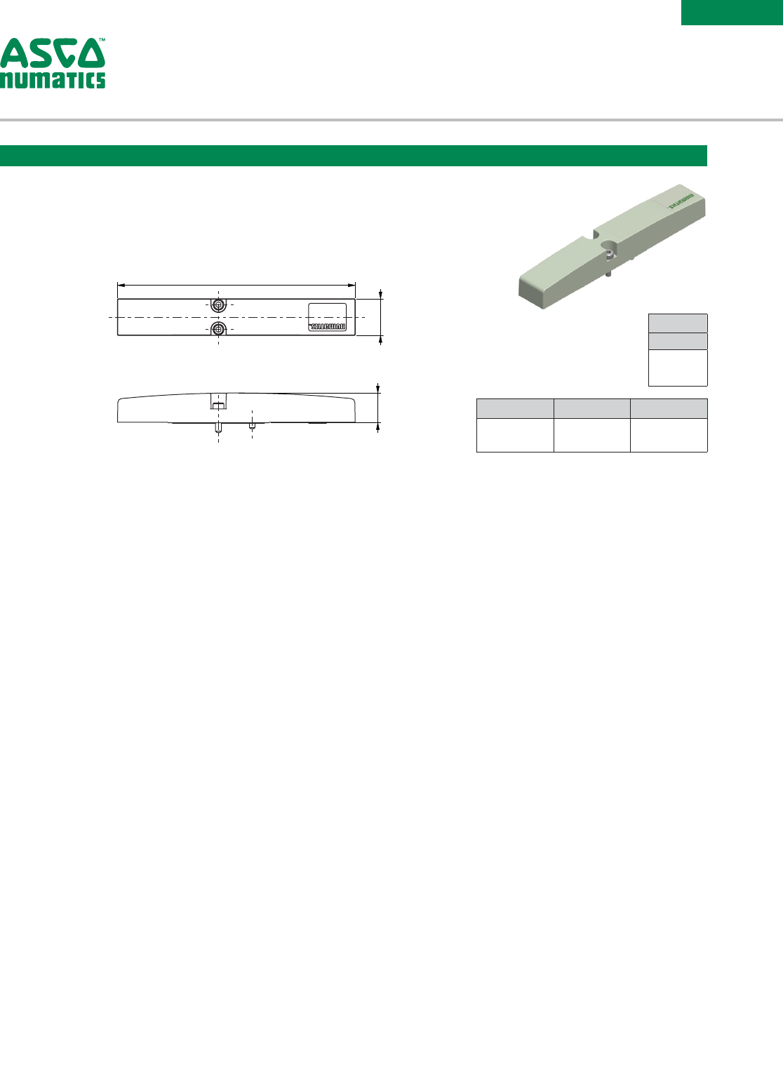
End Plate Kit is used to stack multiple blocks together into a manifold assembly.
Vertical End Plates w/o DIN,
w/Muffler
Vertical End Plates w/o DINHorizontal End Plates w/o DIN
End Plate Kit
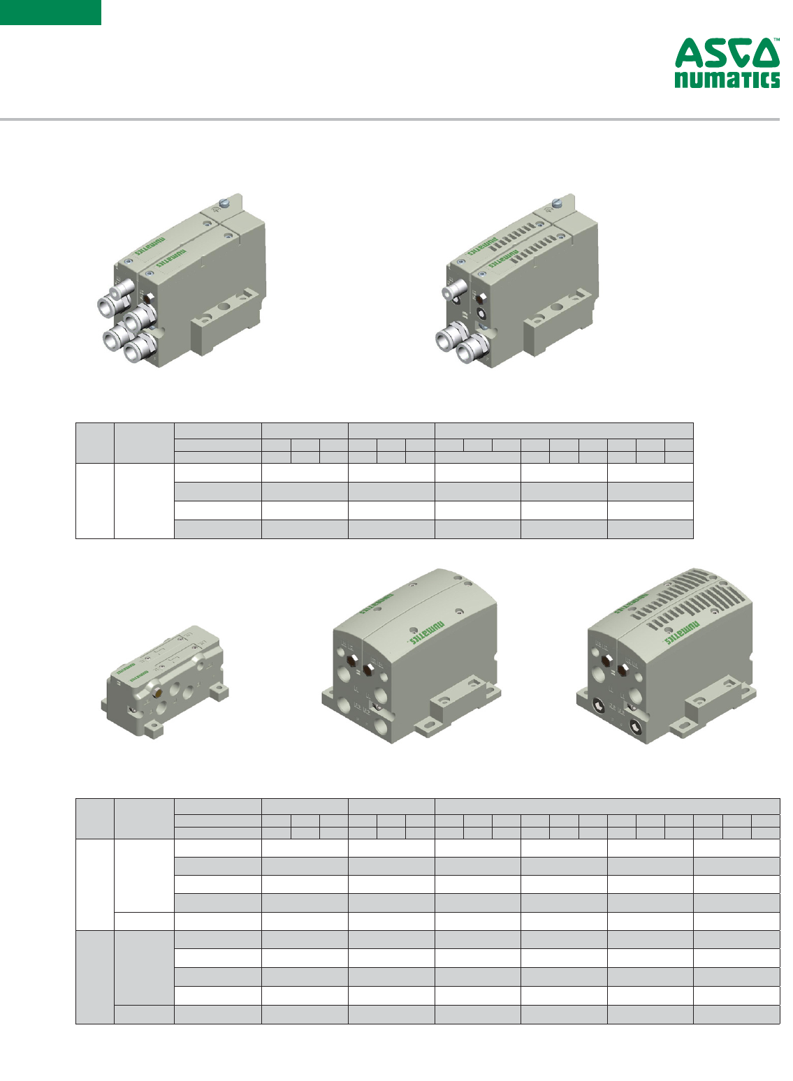
Information subject to change without notice. For ordering information or regarding your local sales office visit www.asco.com. 11
SERIES
501/
502/
503
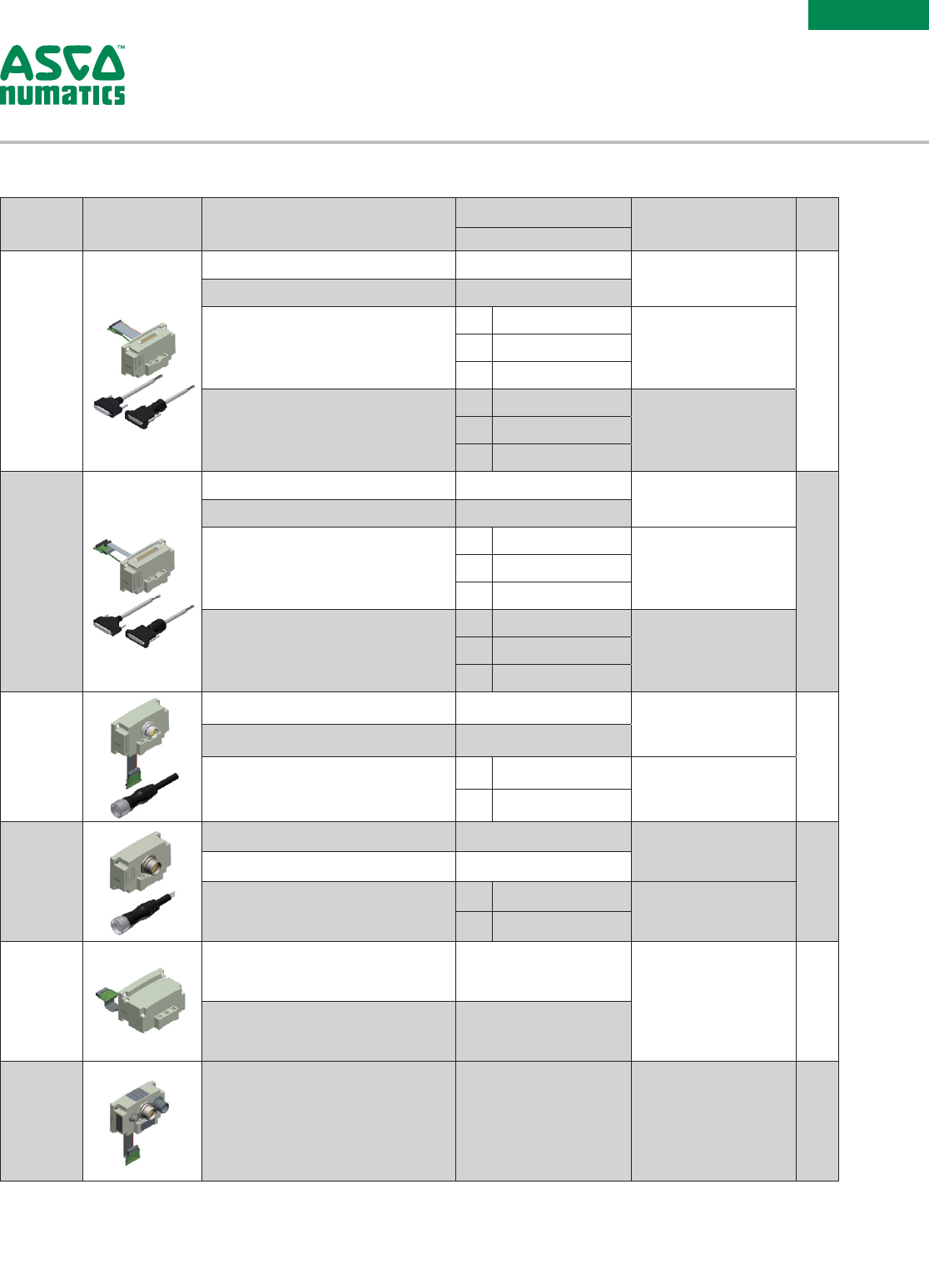
Multipin
Electrical
Interface
Product Image
(Example Only) Description Part Number Notes
Max.
# of
Coils*
501, 502 & 503 Valve Series
25 Pin
Sub-D
Interface
Housing Kit Assembly w/o DIN Rail Clamps P599AE428441001 External fusing or output
protection recommended.
22
Housing Kit Assembly w/DIN Rail Clamps P599AE428441002
Female Cable 22 AWG – Unshielded,
Standard
2m SC2502MCX0000000
–5m SC2505MCX0000000
10m SC2510MCX0000000
Female Cable 22 AWG - Unshielded IP65
2m NDB25F22U02MSB4
–5m NDB25F22U05MSB4
10m NDB25F22U10MSB4
37 Pin
Sub-D
Interface
Housing Kit Assembly w/o DIN Rail Clamps P599AE428442001 External fusing or output
protection recommended.
32
Housing Kit Assembly w/DIN Rail Clamps P599AE428442002
Female Cable 22 AWG – Unshielded,
Standard
2m SC3702MCX0000000
–5m SC3705MCX0000000
10m SC3710MCX0000000
Female Cable 22 AWG - Unshielded IP65
2m NDB37F22U02MSB4
–5m NDB37F22U05MSB4
10m NDB37F22U10MSB4
19 Pin M23
Interface
Housing Kit Assembly w/o DIN Rail Clamps P599AE428436001 External fusing or output
protection recommended.
16
Housing Kit Assembly w/DIN Rail Clamps P599AE428436002
M23 Female Cable
5m CC1905MI00000000
–
10m CC1910MI00000000
26 Pin M27
Interface
Housing Kit Assembly w/o DIN Rail Clamps P599AE502625001 External fusing or output
protection recommended.
22
Housing Kit Assembly w/DIN Rail Clamps P599AE502625002
M27 Female Cable
5m CC2605MI00000000
–
10m CC2610MI00000000
1-32 Pin
Terminal
Strip
Interface
Housing Kit Assembly w/o DIN Rail Clamps P599AE428444001 1) External fusing or output
protection recommended.
2) Min. Wire AWG 26,
Max. Wire AWG 18
32
Housing Kit Assembly w/DIN Rail Clamps P599AE428444002
Robot End
Effector
Interface
Housing Kit Assembly 599AE509838001 M27 connector cable not
provided by ASCO. 8
Multipin Electrical Interface
* Maximum number of valve stations is determined by:
• The electrical connection type.
• The valve type - single solenoid valves up to the maximum solenoid outputs allowed by the electrical connection type (see chart above) or
a combination of single and/or double solenoid valves not to exceed the maximum number of solenoid outputs allowed.
• Combination of all stations cannot exceed 32 solenoids.
Information subject to change without notice. For ordering information or regarding your local sales office visit www.asco.com.
12
SERIES
501/
502/
503
Replacement
Parts Kit
Product Image
(Example Only) Description Parts
Included
Part Number
501 Series (11m m) 502 Series (18mm) 503 Series (26mm)
Interface
Mounting Kit
Includes Mounting Gaskets ((1)valve to base, (2)
Accessories to valve or base, (1) Manifold block, (1)
End-Plate to electrical housing), (1) Body to base O-ring,
(2) Manifold block mounting screws and lock washers, (4)
Electrical housing mounting screws
M501AU521771001 M502AU521772001 M5 03AU5217730 01
Regulator
Replacement
Kit
3 – 30 PSIG Regulator Kit
Includes
regulator
assembly,
gaskets, screws.
–M502AR427995001 M503AR428759001
5 – 60 PSIG Regulator Kit –M502AR427995002 M503AR428759002
10 – 130 PSIG Regulator Kit –M502AR427995003 M503AR428759003
0.2 – 2.0 bar Regulator Kit –M502AR427995004 M503AR428759004
0.3 – 4.0 bar Regulator Kit –M502AR427995005 M503AR428759005
0.7 – 9.0 bar Regulator Kit –M502AR427995006 M503AR428759006
Regulator
Gauge
Replacement
Kit
0 – 160 PSIG Regulator Gauge Head
Extended
Includes gauge
head, o-ring, and
hitch-pin.
–M502AG521734001 –
0 – 160 PSIG Regulator Gauge Head M501AG504541001 M502AG521734002 M503AG521734009
0 – 60 PSIG Regulator Gauge Head
Extended –M502AG521734003 –
0 – 60 PSIG Regulator Gauge Head –M502AG521734004 M503AG521734010
0 – 11 bar Regulator Gauge Head
Extended –M502AG521734005 –
0 – 11 bar Regulator Gauge Head M501AG550540001 M502AG521734006 M503AG521734011
0 – 4 bar Regulator Gauge Head
Extended –M502AG521734007 –
0 – 4 bar Regulator Gauge Head –M502AG521734008 M503AG521734012
Replacement Parts Kit
Accessories
Kit
Product Image
(Example Only) Description Port
Number
Part Number
501 Series (11m m) 502 Series (18mm) 503 Series (26mm)
Blank Station
Plate Kit
Used to block off a manifold
station for future use. –P501AB429685001 P502AB431813001 P503AB428359001
DIN Rail
Clamp Kit
Used to mount manifold
assembly to a machine via DIN
Rail. Kit includes hardware for
each end of the manifold.
NOTE: DIN Rail not included.
–239-980
Blocking
Disc Kit
Used to isolate 1, 3 & 5 galleries
of the manifold internally.
NOTE: Includes tag to label
ports blocked.
1P501AD431915001 P502AD431914001 P 5 0 3A D 4 3119 10 0 1
3P501AD431915002 P502AD431914002 P 5 0 3A D 4 3119 10 0 2
5P501AD431915003 P502AD431914003 P503AD431191003
1 + 3 P501AD431915004 P502AD431914004 P503AD431191004
1 + 5 P501AD431915005 P502AD431914005 P503AD431191005
3 + 5 P501AD431915006 P502AD4319140 06 P 5 03 A D 4 3119 10 0 6
1, 3, 5 P501AD431915007 P502AD431914007 P 5 0 3A D 4 3119 10 0 7
Internal
Mufer
Element
Mufer element –501: 427991-001, 502: 429372-001, 503: 426186-001
Thread Type Tube Size Quantity 501 Series (11m m) 502 Series (18mm) 503 Series (26mm)
Fittings
M7 4mm 10 H850A104B004B10
See Fittings Catalog See Fittings Catalog
M7 6mm 10 H850A104B006B10
M7 1/4in 10 H850A104B104B10
Accessories Kit
Information subject to change without notice. For ordering information or regarding your local sales office visit www.asco.com. 13
SERIES
501/
502/
503
Example Order - 502 & 501 Manifold Shown
25 Pin Sub-D 8502AVJH321VA00
Valve Station #1 R502A2B40MA00F1
Valve Station #2 R502A2B40MA00F1
Mounting #1 8502AMM21MA0010
Valve Station #3 R502A2B40MA00F1
Valve Station #4 R502A2B40MA00F1
Mounting #2 8502AMM21MA0010
Valve Station #5 R501A2B40MA00F1
Valve Station #6 R501A2B40MA00F1
Valve Station #7 R501A2B40MA00F1
Valve Station #8 R501A2B40MA00F1
Mounting #3 H501AMM4BMA0010
Assembled
Ordering Adaptor Plate Kit
Valve Series Product Image
(Example Only) Type Description Port Size Thread Type Part Number
503 Series
(26mm)
to
502
Series
(18mm)
ISO 15407-2 503 to 502 Adaptor Plate
w/PCB
3/8"
NPTF
8503 AT4299 640 01
ISO 15407-1
503 to 502 Adaptor Plate
w/o PCB
(for ISO 15407-1 Mounting)
8503 AT4299 640 02
ISO 15407-2 503 to 502 Adaptor Plate
w/PCB
G Tap
G503AT429964003
ISO 15407-1
503 to 502 Adaptor Plate
w/o PCB
(for ISO 15407-1 Mounting)
G503AT429964004
502 Series
(18mm)
to
501
Series
(11mm)
ISO 15407-2 502 to 501 Adaptor Plate
w/PCB NPTF 8502AT429963001
ISO 15407-1 502 to 501 Adaptor Plate
w/PCB G Tap G502AT429963002
The adaptor plate allows the transition from 503 Series to 502 Series and 502 Series to 501 Series in a single
manifold assembly. Includes the adapter plate, transfer board, gasket, screws.
Adaptor Plate Kit
* Example purpose only.
NOTE: When looking at Cylinder Ports, Adaptor Plate can only be used
to transition from 503 Series to 502 Series or 502 Series to 501
Series valves starting from the left side of a manifold assembly.
Adaptor Plate can only be used to transition from 503 Series
to 502 Series or 502 Series to 501 Series. When looking at the
cylinder ports the valves start from the electronics (left to right)
side of a manifold assembly.
503 to 502
or
502 to 501*
Information subject to change without notice. For ordering information or regarding your local sales office visit www.asco.com.
14
SERIES
501/
502/
503
Individual Subbase/External Pilot Selection
501
Series
(11mm)
502
Series
(18mm)
503
Series
(26mm)
Image
(Example Only)
Image
(Example Only
Image
(Example Only
Valve
Mounting Gasket
Regulator
Mounting Gasket
Speed Control
Mounting Gasket
Manifold Block
Interface Gasket
Plug-In Valve, Regulator, Speed Control, and Manifold Block Assembly Example
External Pilot
Supply Plug Location
External Pilot
Internal Pilot
Supply Plug Location
Internal Pilot
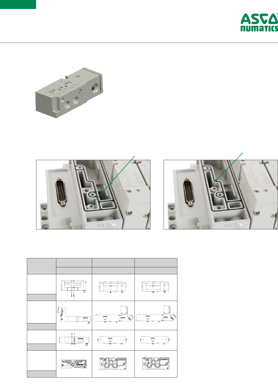
NOTE: Base assemblies are supplied set up for internal pilot supply. To convert to external pilot supply install M4 plug P.N. 129-216 (sold separately) down
inside in the pressure port (1). Remove the 1/8 pipe plug from port 14 to supply pilot pressure.
Pilot Selection
NOTE: Manifold Block is supplied set up for internal pilot supply. To convert to external pilot supply install pilot supply seal screws 501 Series: 127-803,
502 & 503 Series: 426188-001, as shown in the pictures.
Manifold Assembly Internat/External Pilot Selection
Information subject to change without notice. For ordering information or regarding your local sales office visit www.asco.com. 15
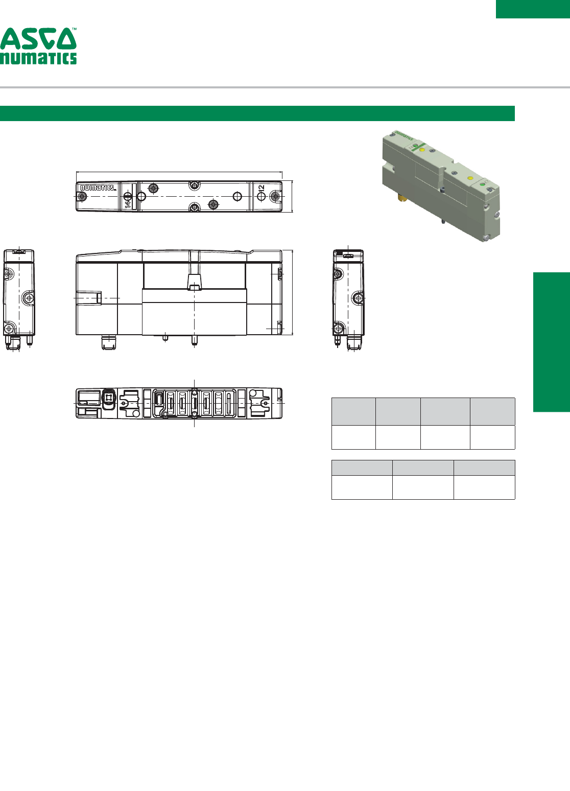
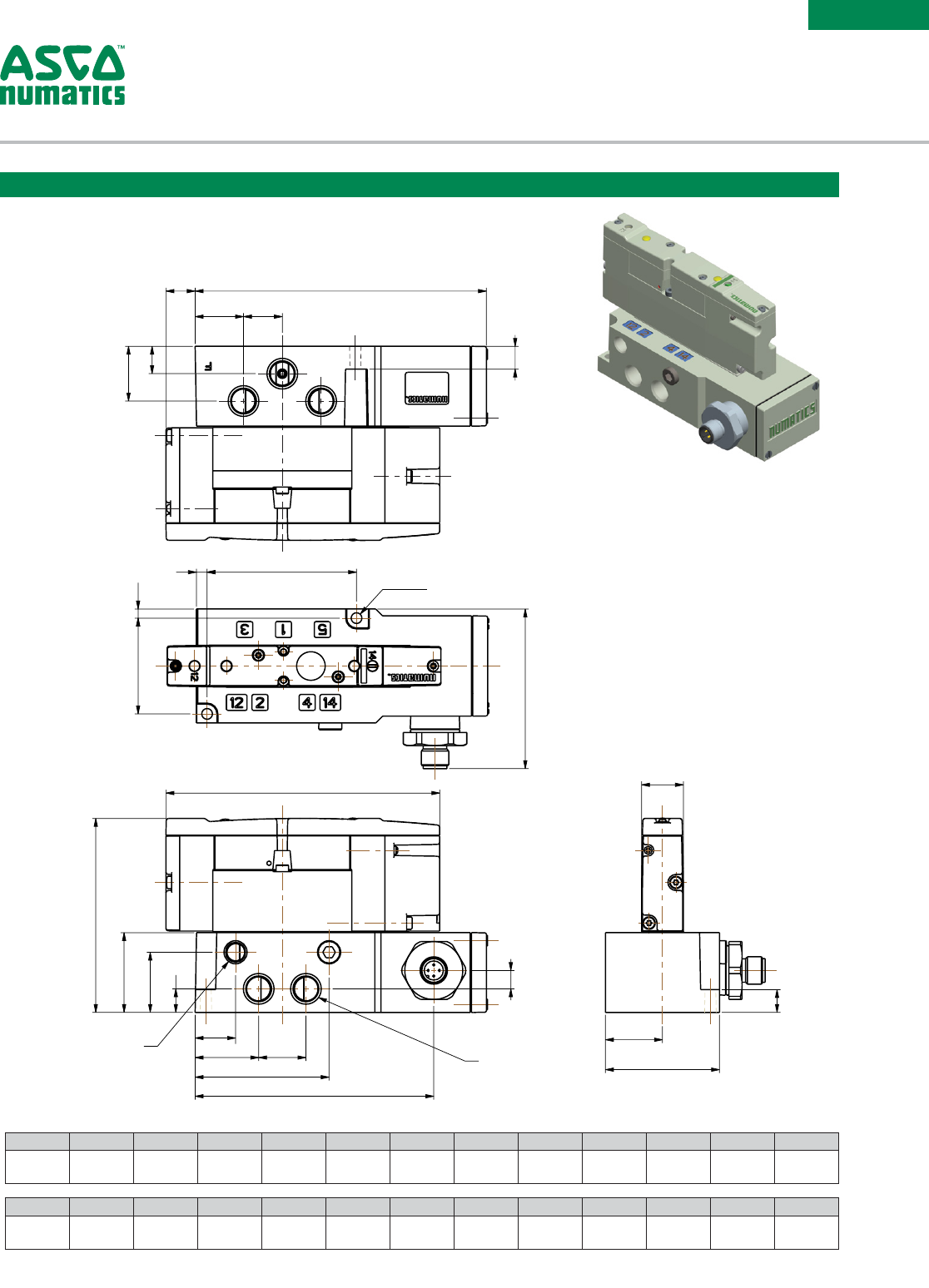
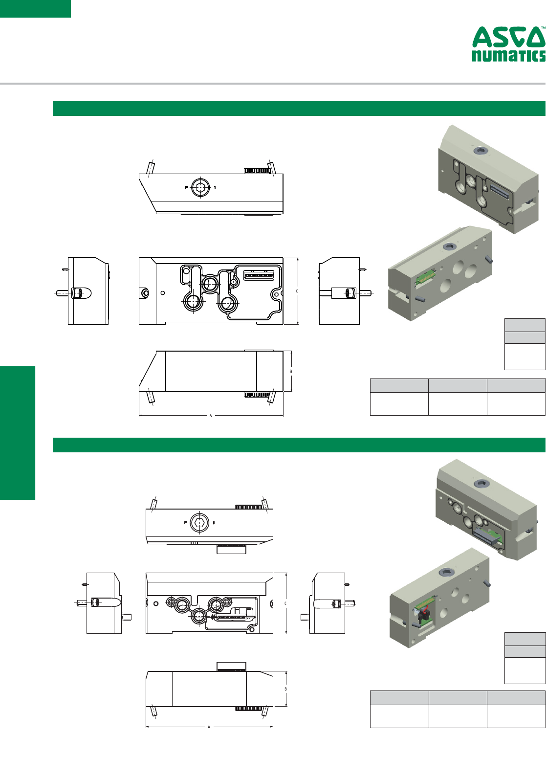
SERIES
502
502 SERIES
DIMENSIONAL DRAWINGS
C
B
A
502 Series Plug-In Valve
Dimensions: mm (inches)
A B C
120
(4.72)
18
(0.71)
49.6
(1.95)
Weight Valve
Body
Manifold
Block
End
Plates
lbs
(kg)
0.372
(0 .16 9)
0.75
(0.34)
3.30
(0.45)
Information subject to change without notice. For ordering information or regarding your local sales office visit www.asco.com.
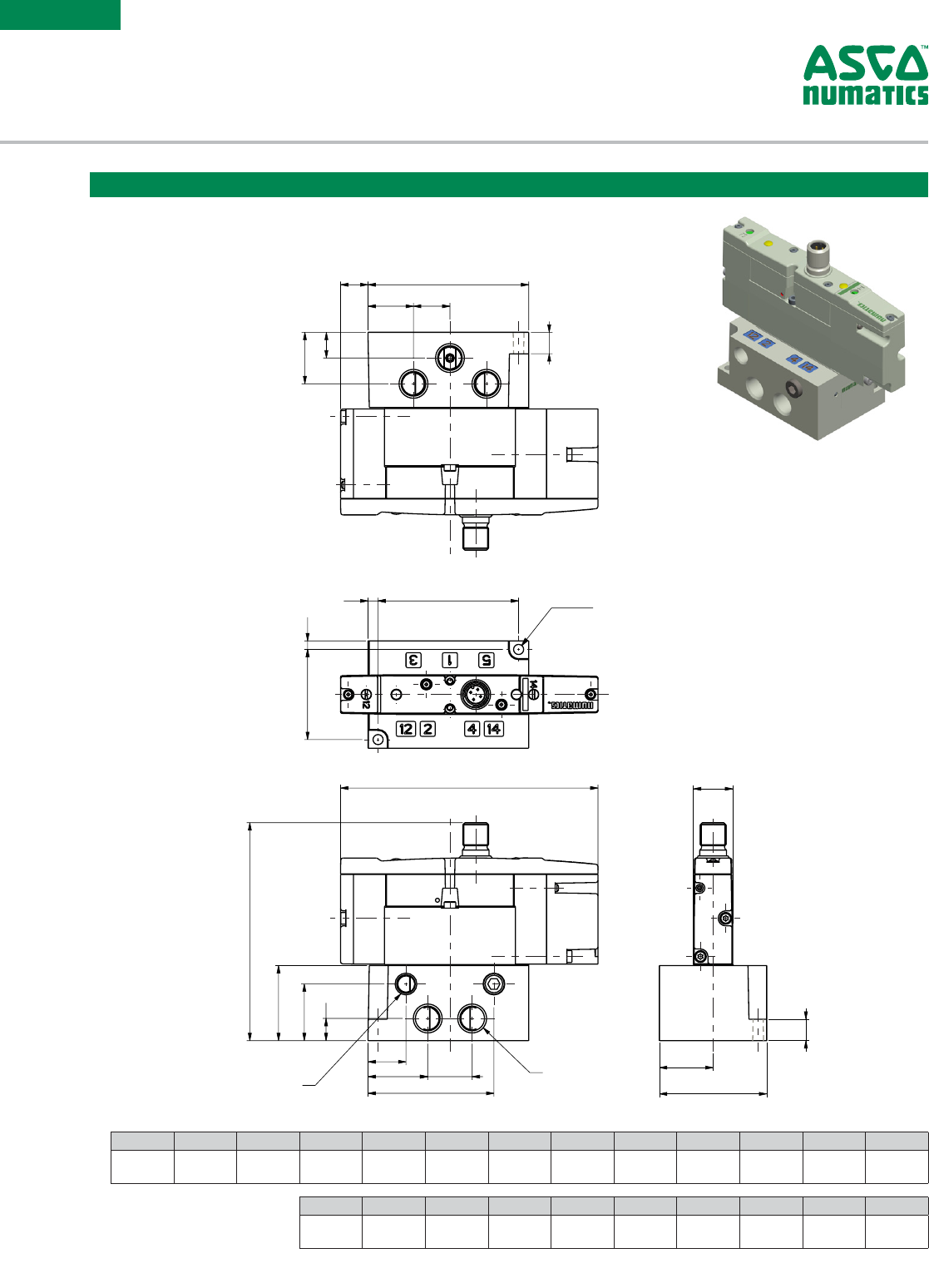
16
SERIES
502
G
F
E
D
A
B
C
H
A B C D E F G H
10 7.1
(4.217)
42.3
(1.665)
14.8
(0.583)
38
(1.496)
29.4
(1.157 )
12.2
(0.48)
3 7. 3
(1.469)
120
(4.724)
Plug-In Valve Mounted
Plug-In Manifold Block
Dimensions: mm (inches)
Information subject to change without notice. For ordering information or regarding your local sales office visit www.asco.com. 17
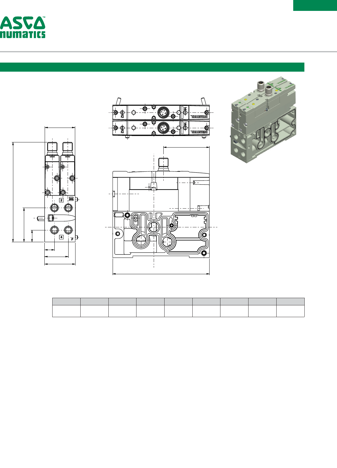
SERIES
502
G
A
B
C
F
E
D
H
J
A B C D E F G H J
123.6
(4.866)
42.3
(1.665)
14.8
(0.583)
38
(1.496)
29.4
(1.157 )
12.2
(0.48)
3 7. 3
(1.469)
120
(4.724)
57
(2.244)
M12 Valve Mounted
Non Plug-In Manifold Block (ISO 15407-1)
Dimensions: mm (inches)
Information subject to change without notice. For ordering information or regarding your local sales office visit www.asco.com.
18
SERIES
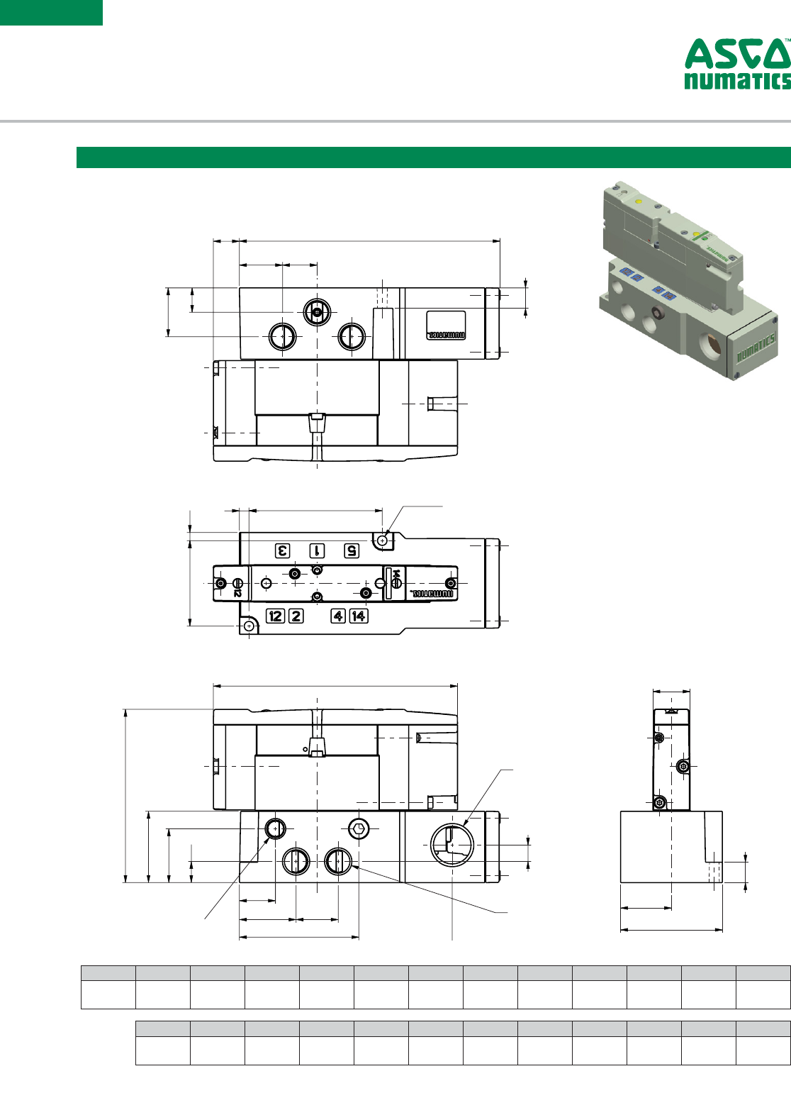
502
Dimensions: mm (inches)
N
P
Q
RLH
JK
B
A
G
F
CD
E
Ø4,7
(2) Holes
M
W
V
U
T
S
1/4 NPTF or G Tap
(5) Ports
1/8 NPTF or G Taps
(2) Ports
X
1/2 NPTF Tap
Conduit
Y
E
Z
AA
A B C D E F G H J K L M N
12.8
(0.504)
128.1
(5.043)
21.2
(0.835)
17
(0.669)
10
(0.394)
12
(0.472)
24
(0.945)
4
(0.157 )
4.7
(0.18 5 )
65.5
(2.579)
42
(1.654)
120
(4.724)
85 .1
(3.35)
P Q R S T U V W X Y Z AA
35
(1.378)
26.4
(1.039)
10.4
(0.409)
17.7
(0.697)
27. 9
(1.098)
20.7
(0.815)
58.7
(2. 311)
104.6
(4.118 )
8.1
(0.319)
18.3
(0.72)
25
(0.984)
50
(1.969)
Plug-In Individual Subbase
Plug-In Valve on Individual Subbase
Information subject to change without notice. For ordering information or regarding your local sales office visit www.asco.com. 19
SERIES
502
1/4 NPTF or G Tap
(2) Ports
1/8 NPTF or G Tap
(2) Ports
Y
X
W
VU
T
S
P
Q
R
N
LH
JK
Ø4,7
(2) Holes
M
BA
G
F
CD
E
E
AB
AA
Z
A B C D E F G H J K L M N
12.8
(0.504)
128.1
(5.043)
21.2
(0.835)
17
(0.669)
10
(0.394)
12
(0.472)
24
(0.945)
4
(0.157 )
4.7
(0.18 5 )
65.5
(2.579)
42
(1.654)
70
(2.756)
120
(4.724)
P Q R S T U V W X Y Z AA AB
85 .1
(3.35)
35
(1.378)
26.4
(1.039)
10.4
(0.409)
17.7
(0.697)
27. 9
(1.098)
20.7
(0.815)
58.7
(2. 311)
104.6
(4.118 )
8.1
(0.319)
18.3
(0.72)
25
(0.984)
50
(1.969)
Plug-In Valve on Individual Subbase
M12 Individual Subbase (ISO 15407-2)
Dimensions: mm (inches)
Information subject to change without notice. For ordering information or regarding your local sales office visit www.asco.com.
20
SERIES
502
Non Plug-In Valve on Individual Subbase
Non Plug-In Individual Subbase (ISO 15407-1)
A B C D E F G H J K L M N
12.8
(0.504)
74. 9
(2.949)
21.2
(0.835)
17
(0.669)
10
(0.394)
12
(0.472)
24
(0.945)
4
(0.157 )
4.7
(0.18 5 )
65.5
(2.579)
42
(1.654)
120
(4.724)
101.6
(4)
P Q R S T U V W X Y
35
(1.378)
26.4
(1.039)
10.4
(0.409)
17.7
(0.697)
27. 9
(1.098)
20.7
(0.815)
58.7
(2. 311)
18.3
(0.72)
25
(0.984)
50
(1.969)
B
A
G
F
E
DC
J
H
K
L
Ø4,7
(2) Holes
M
N
P
Q
R
S
TU
V
1/4 NPTF or Tap
(5) Ports
1/8 NPTF or G Tap
(2) Ports
W
E
Y
X
Dimensions: mm (inches)
Information subject to change without notice. For ordering information or regarding your local sales office visit www.asco.com. 21
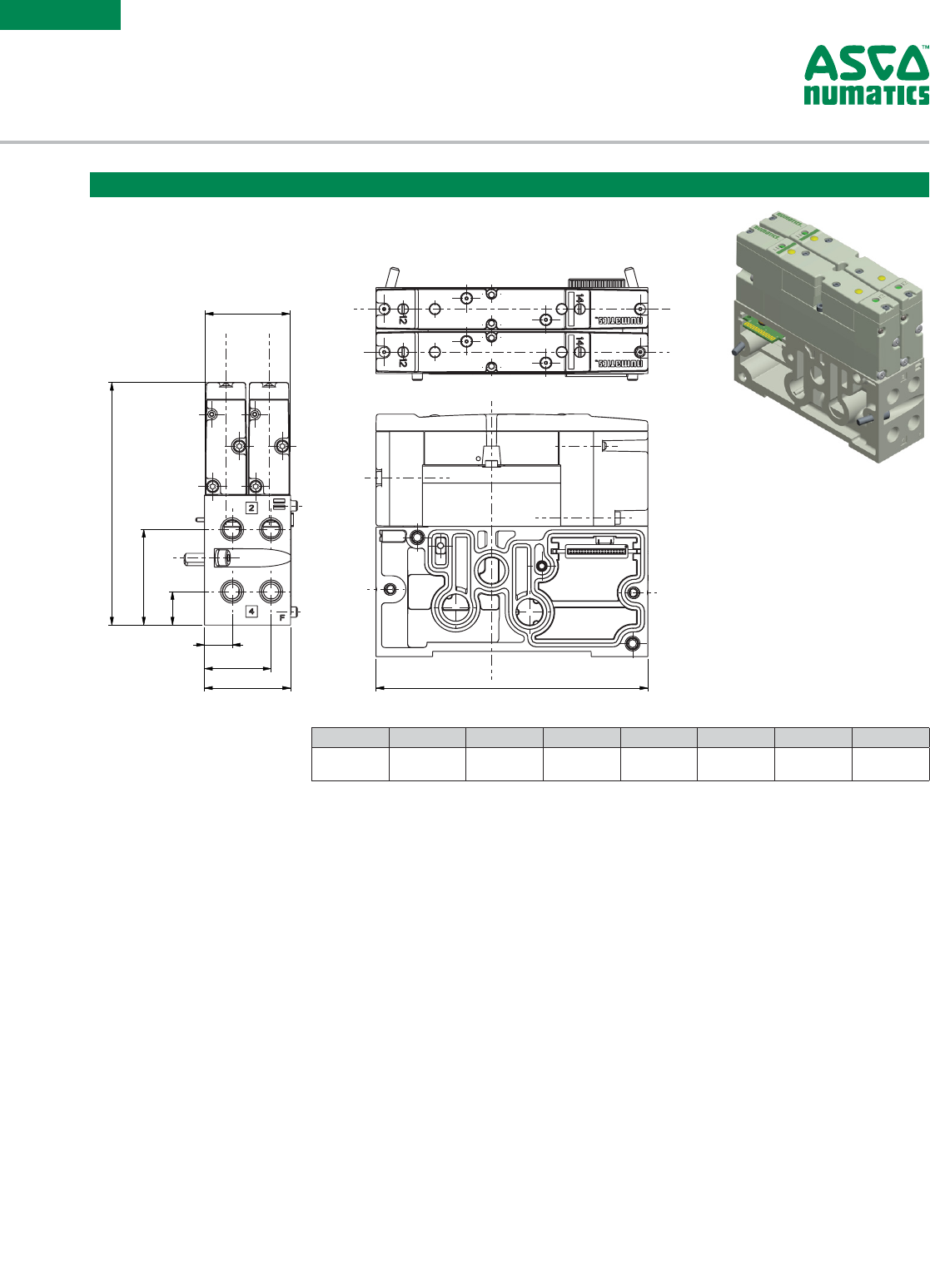
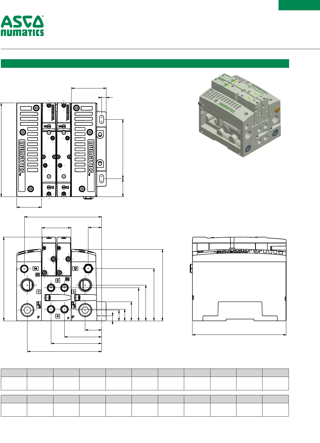
SERIES
502
Manifold Assembly
C
D
E
F
B
A
H
K
J
G
X
W
V
U
T
S
R
G
P
N
M
L
A Ref.
Dimensions: mm (inches)
A B C D E F G H J K L
120
(4.724)
31.9
(1.256)
44.9
(1.768)
6
(0.236)
75.8
(2.984)
23 .1
(0.909)
107.1
(4.217)
98.9
(3.894)
3 7. 3
(1.469)
17.1
(0.673)
91.6
(3.606)
M N P Q R S T U V W X
66.9
(2.634)
45.7
(1.799)
42.3
(1.665)
24.4
(0.961)
14.8
(0.583)
13.7
(0.539)
6.35
(0.25)
21
(0.827)
47. 5
(1.87)
64.7
(2.547)
95
(3.74)
Information subject to change without notice. For ordering information or regarding your local sales office visit www.asco.com.
22
SERIES
502
A
BF
E
D
C
A B C D E F
261.2
(10.283)
139.6
(5.496)
73.5
(2.894)
35.6
(1.402)
18.6
(0.732)
9.3
(0.366)
Double Regulator
Dimensions: mm (inches)
A B C D E F
190.6
( 7. 5 0 4 )
139.6
(5.496)
73.5
(2.894)
35.6
(1.402)
18.6
(0.732)
9.3
(0.366)
Single Regulator
Sandwich Pressure Regulator
Dimensions: mm (inches)
B
A
F
E
D
C
Weight
lbs (kg)
0.65
(0.30)
Weight
lbs (kg)
1.05
(0.48)
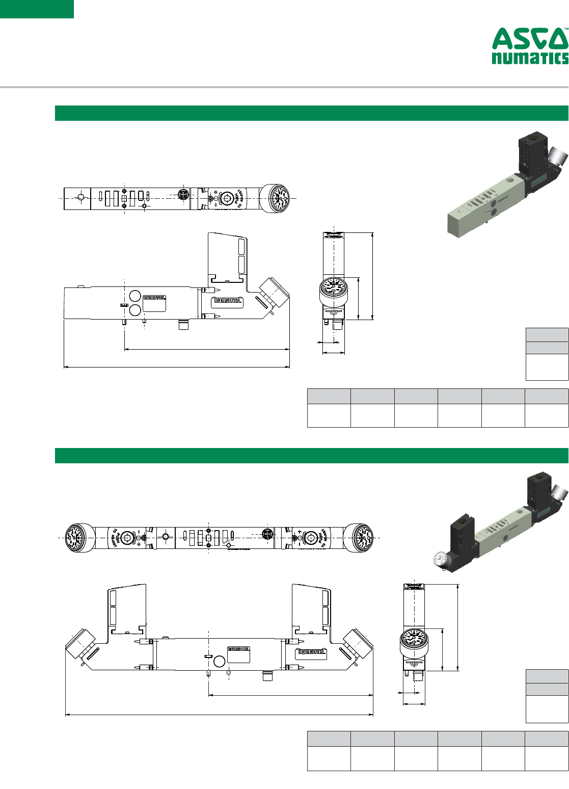
Information subject to change without notice. For ordering information or regarding your local sales office visit www.asco.com. 23
SERIES
502
Sandwich Pressure Block Kit
Dimensions: mm (inches)
A
1
B
C
D
A B C D
129.2
(5.087)
51
(2.008)
2 7. 5
(1.083)
18.5
(0.728)
A
B
C
D
A B C D
147. 2
(5.795)
51
(2.008)
2 7. 5
(1.083)
18.5
(0.728)
Sandwich Shut Off Block Kit
Dimensions: mm (inches)
Weight
lbs (kg)
0.30
(0 .14)
Weight
lbs (kg)
0.50
(0.23)
Information subject to change without notice. For ordering information or regarding your local sales office visit www.asco.com.
24
SERIES
502
A
B
D
C
A B C D
124
(4.882)
53
(2.087)
2 7. 5
(1.083)
18.5
(0.728)
Sandwich Speed Control Kit
Dimensions: mm (inches)
35
D
C
B
A
A B C D
138.4
(5.449)
60.2
(2.37)
2 7. 5
(1.083)
18.5
(0.728)
Sandwich Exhaust Block Kit
Dimensions: mm (inches)
Weight
lbs (kg)
0.30
(0 .14)
Weight
lbs (kg)
0.30
(0 .14)
Information subject to change without notice. For ordering information or regarding your local sales office visit www.asco.com. 25
SERIES
502
Blank Station Plate Kit
Dimensions: mm (inches)
A
B
C
A B C
120
(4.724)
18.5
(0.728)
15
(0.591)
Weight
lbs (kg)
0 .10
(0.05)
Information subject to change without notice. For ordering information or regarding your local sales office visit www.asco.com.
26
SERIES
501/
502/
503
ADAPTOR PLATE
DIMENSIONAL DRAWINGS
A B C
120
(4.72)
33.5
(1.32)
5 7. 5
(2.26)
Weight
lbs (kg)
1.05
(0.48)
Adaptor Plate Kit
502 Valve Series to 501 Valve Series
Dimensions: mm (inches)
A B C
136
(5.35)
38.25
(1.51)
63
(2.48)
Weight
lbs (kg)
1.50
(0.68)
Adaptor Plate Kit
503 Valve Series to 502 Valve Series
Dimensions: mm (inches)
Information subject to change without notice. For ordering information or regarding your local sales office visit www.asco.com. 27
SERIES
501/
502/
503
ELECTRICAL INTERFACE
DIMENSIONAL DRAWINGS
J
K
A
BC
Ø5.5
G
H
F
ED
A B C D E F G H J K
46.4
(1.827)
17
(0.669)
6.7
(0.26)
118
(4.65)
3 7. 5
(1.48)
59
(2.32)
40.2
(1.58)
40.2
(1.58)
68.1
(2.68)
24.4
(0.96)
Weight
lbs (kg)
0.70
(0.32)
37 Pin Sub-D Connector Kit
Dimensions: mm (inches)
J
K
A
BC
Ø5.5
G
H
F
ED
A B C D E F G H J K
46.4
(1.827)
17
(0.669)
6.7
(0.26)
118
(4.65)
3 7. 5
(1.48)
59
(2.32)
40.2
(1.58)
40.2
(1.58)
68 .1
(2.68)
24.4
(0.96)
Weight
lbs (kg)
0.70
(0.32)
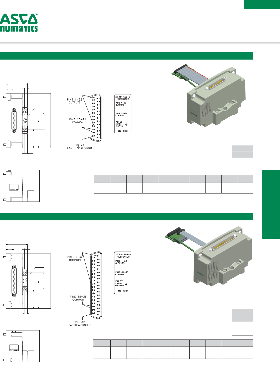
25 Pin Sub-D Connector Kit
Dimensions: mm (inches)
MULTIPIN ELECTRICAL
INTERFACE
Information subject to change without notice. For ordering information or regarding your local sales office visit www.asco.com.
28
SERIES
501/
502/
503
A
C
E
G
D
K
J
L
M
19 PIN CONNECTOR
PIN 10= COIL 14
PIN 9= COIL 10
PIN 8= COIL 6
PIN 7= COIL 2
PIN 6= COMMON
PIN 5= COIL 3
PIN 4= COIL 4
PIN 3= COIL 7
PIN 2= COIL 11
PIN 1= COIL 15
PIN 19= N.C.
PIN 11= COIL 13
PIN 12= P. E.
PIN 13= COIL 12
PIN 14= COIL 8
PIN 15= COIL 1
PIN 16= COIL 5
PIN 17= COIL 9
PIN 18= COIL 16
8
1465
3
9
2
7
Ø5.2
A
C
D
N
P
KQ
J
1/2 NPTF Tap
E
FG
A C D E G J K L M
56.3
(2.217)
6.7
(0.26)
118
(4.65)
3 7. 5
(1.48)
40.2
(1.583)
68.1
(2.68)
24.4
(0.96)
40.8
(1.61)
59
(2.323)
19 Pin Round Connector Kit
Dimensions: mm (inches)
A C D E F G J K N P Q
82.7
(3.256)
7
(0.28)
118
(4.65)
37.5
(1.48)
59
(2.32)
40.2
(1.583)
68.1
(2.68)
24.4
(0.96)
9.8
(0.39)
41.9
(1.65)
19.3
(0.76)
1-32 Terminal Strip Kit
Dimensions: mm (inches)
MULTIPIN ELECTRICAL
INTERFACE
Weight
lbs (kg)
1.20
(0.54)
Weight
lbs (kg)
0.70
(0.32)
Information subject to change without notice. For ordering information or regarding your local sales office visit www.asco.com. 29
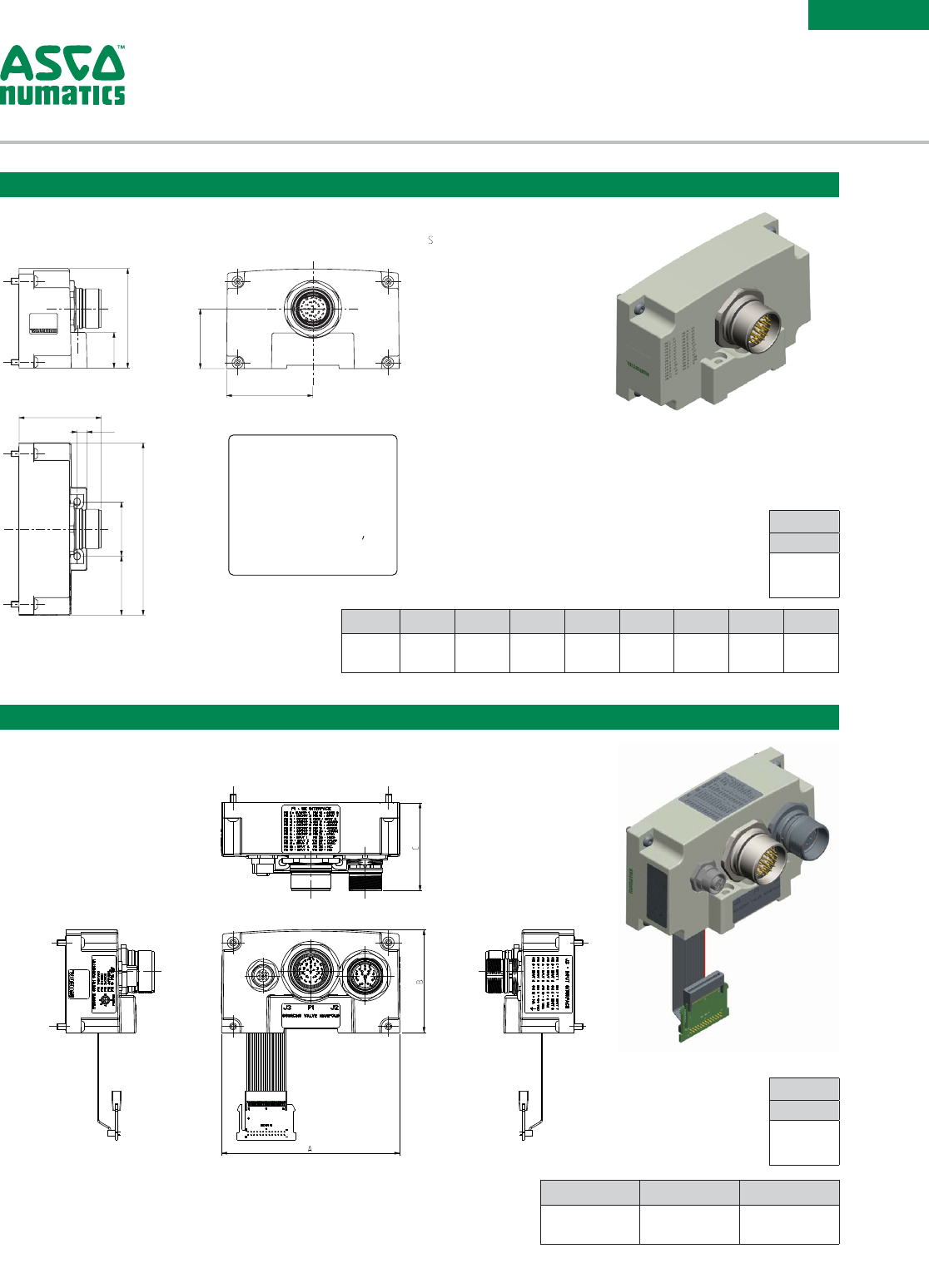
SERIES
501/
502/
503
Robot End Effector Interface
Dimensions: mm (inches)
E
DC
B
A
J
H
G
F
PIN 1= V1
PIN 2= V2
PIN 3= V3
PIN 4= V4
PIN 5= V5
PIN 6= V6
PIN 7= V7
PIN 8= V8
PIN 9= V9
PIN 10= V10
PIN 11= V11
PIN 12= V12
PIN 13= V13
PIN 14= V14
PIN 15= V15
PIN 16= V16
PIN 17= V17
PIN 18= V18
PIN 19= V19
PIN 20= V20
PIN 21= V21
PIN 22= V22
PIN 23= N/A
PIN 24= COM
PIN 25= COM
PIN 26= PE
26 PIN CONNECTOR
A B C D E F G H J
56.1
(2.209)
6.7
(0.264)
118
(4.65)
3 7. 5
(1.48)
40.2
(1.58)
68.1
(2.68)
24.4
(0.961)
40.8
(1.61)
59
(2.32)
26 Pin Round Connector Kit
Dimensions: mm (inches)
MULTIPIN ELECTRICAL
INTERFACE
Weight
lbs (kg)
0.70
(0.32)
Weight
lbs (kg)
0.90
(0.41)
A B C
118
(4.65)
68.1
(2.68)
58.4
(2.30)


www.asco.com
ASCO Headquarters (USA) | Tel (1) 800.972.2726 | e-mail: info-valve@asco.com
ASCO Numatics (USA) | Tel (1) 888-686-2842 | e-mail: an.insidesales@emerson.com
Netherlands
(31) 33 -277-7911
Singapore
(65) 6556-1100
South Korea
(82) 2-3483-1570
Spain
(34) 942-87-6100
United Kingdom
(44) 1695-713600
France
(33) 2-37-24-42-24
Germany
(49) 7237-9960
India
(91) 44-39197300
Italy
(39) 02-356931
Japan
(81) 798-65-6361
Mexico
(52) 55-5809-5640
Australia
(61) 2-9-451-7077
Brazil
(55) 11-4208-1700
Canada
(1) 519-758-2700
China
(86) 21-3395-0000
Czech Republic
(420) 235-090-061
Dubai - UAE
(971) 4 811 8200
Global Contacts
06/17
