Flow Numatics L01 Series Solenoid Valve 1507232629 User Manual
Numatics L01 Series Solenoid Valve-1507232629 NUMATICS_L01_SERIES_SOLENOID_VALVE-1507232629 NUMATICS_L01_SERIES_SOLENOID_VALVE-1507232629 NUMATICS L01 SERIES SOLENOID VALVE Solenoid Valves s production assets-flotronics
Numatics L01 Series Solenoid Valve NUMATICS L01 SERIES SOLENOID VALVE NUMATICS L01 SERIES SOLENOID VALVE Solenoid Valves Pneumatic Valves client_assets assets-flotronics 3:
2017-10-05
User Manual: Flow Numatics L01 Series Solenoid Valve-1507232629
Open the PDF directly: View PDF ![]() .
.
Page Count: 10
L01 Series
Direct Solenoid Actuated Valves
www.numatics.com

Table of Contents
L01 Series
Technical and Operating Data 3
How to Order 4
Valve Dimensions 5
Manifold Assembly 6
Speed Control Kit 7
Mounting Kit 7
Blank Station Plate Kit 7
Solenoid Capsule Assemblies 7
Valve Service Kits and Parts 8-9
Information subject to change without notice. For ordering information or regarding your local sales office visit www.numatics.com.
3
L01
SERIES
single solenoid
2 position 4-way
double solenoid
2 position 4-way
double solenoid
3 position 4-way
open center
double solenoid
3 position 4-way
closed center
12 14
2 4
3 1 3 1
12 14
2 4
12 14
2 4
3 1
12 14
2 4
3 1
double solenoid, spring centered
3 position 4-way pressure center
1214 2
4
315
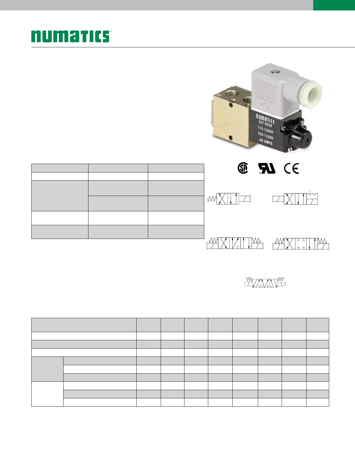
4 Ported, 2 and 3 position, 4-way, Spool & Sleeve
Cv: 0.20
• Direct solenoid actuated
• DIN plug-in solenoid with indicator light
• Unlubricated or lubricated service
• Integral speed control available
• In-line or manifold mounted
• Designed to meet the requirements of NEMA 4 / IP65
Technical Data
Operating Data
Valve Data English Metric
Cv 1/8 = 0.20 1/8 G Tap = 0.20
Flow Capacity
9.3 SCFM 197 NI/m
Upstream pressure to
atmosphere @80 PSIG
@ 6 bar upstream/5 bar
downstream
Operating Pressure Range 28”Hg Vacuum to 150
PSIG Vacuum to 10 bar
Temperature Range
(Ambient) -10°F to + 115°F -23˚C to +46° C
All Solenoids Are Continuous Duty
Rated
12 VDC 24 VDC 24 VAC
50 Hz
24 VAC
60 Hz
115 VAC
50 Hz
120 VAC
60 Hz
230 VAC
50 Hz
240 VAC
60 Hz
Power (Watts) 6.0 6.0 4.0 3.0 5.4 4.1 5.0 5.4
Holding Current (Amps.) 0.500 0.250 0.290 0.023 0.600 0.050 0.024 0.024
Inrush Current (Amps.) N/A N/A 0.490 0.045 0.100 0.090 0.041 0.041
Energize in
seconds
2-Position, Single, Spring Return 0.012 0.012 0.008 0.008 0.008 0.008 0.008 0.008
2-Position, Double, Detented 0.012 0.012 0.008 0.008 0.008 0.008 0.008 0.008
3-Position, Spring Centered 0.012 0.012 0.010 0.010 0.010 0.010 0.010 0.010
De-energize
in seconds
2-Position, Single, Spring Return 0.006 0.006 0.010 0.010 0.010 0.010 0.010 0.010
2-Position, Double, Detented N/A N/A N/A N/A N/A N/A N/A N/A
3-Position, Spring Centered 0.006 0.006 0.012 0.012 0.012 0.012 0.012 0.012
Information subject to change without notice. For ordering information or regarding your local sales office visit www.numatics.com.
4
L01
SERIES
BL01 SS 59
V
alve Series & Port Size
L01 = 1/8
V
alve Type
SA = Single Direct Solenoid, Spring Return
W/Flush Non-locking Override
SS = Double Direct Solenoid w/Flush
Non-locking Override
Function
4 = 2 Position, 4-Way
5 = 3 Position, 4-Way Open Center
6 = 3 Position, 4-Way Closed Center
7 = 3 Position, 4-Way Pressure Center
Mounting
59 = Line Mounted, Common Exhaust
87 = 59 w/Speed Control
Voltage
20 = 24/50-60 VAC
30 = 110-120/50-60 VAC
40 = 220-240/50-60 VAC
60 = 12 VDC
61 = 24 VDC
Options
11B = Flush Locking Override
11Z = Extended Locking Override
13A = 48" Leads
17N = DC Solenoid W/Surge
Suppression Diode
18D = Side Ports
Port Type
0 = NPTF
G = G Tap
Wiring Option
2 = Din Plug-in AC Solenoid
4 = Din Plug-in DC Solenoid
O = Hardwired AC
B = Hardwired DC
40000 60
0000AK 0E
Electrical/Electronics
Type & Location
0 Standard
Valve Line
1 L01 Series
Number of Valve Stations
B2 6J =10
C3 7K11
D4 8L
=
=12
E
=
=
=
=
=
=5
F
G
H
I9
=
=
=
=
Options
STD = Standard
Port Type
N NPTF
G
=
=G tap
End Plate Port Size
2=1/4
12N STD
Example order:
List in order, left to right, facing cylinder ports
Assembly Kit: AK01C00002NSTD
Station 1 LO1SS4872000030
Station 2 LO1SS4592000030
Station 3 LO1SA4592000030
ASSEMBLED
Manifold Assembly
NOTE: Plug connector is NOT included with DIN solenoid. Order plug-in connector assembly separately (see ordering information below)
Plug Connector Descripiton Part No.
Grey (14 end solenoid) Plug Assembly
230-363
Black (12 end solenoid) Plug Assembly
230-364
Plug Assembly with 24 V Light
230-365
Plug Assembly with 110 V Light
230-366
Plug Assembly with 220 V Light
230-367
Normal Polarity
1= (+) Positive, High
2=(-) Negative, Neutral
=Chassis Ground
A
B
CD
E
F
1
2
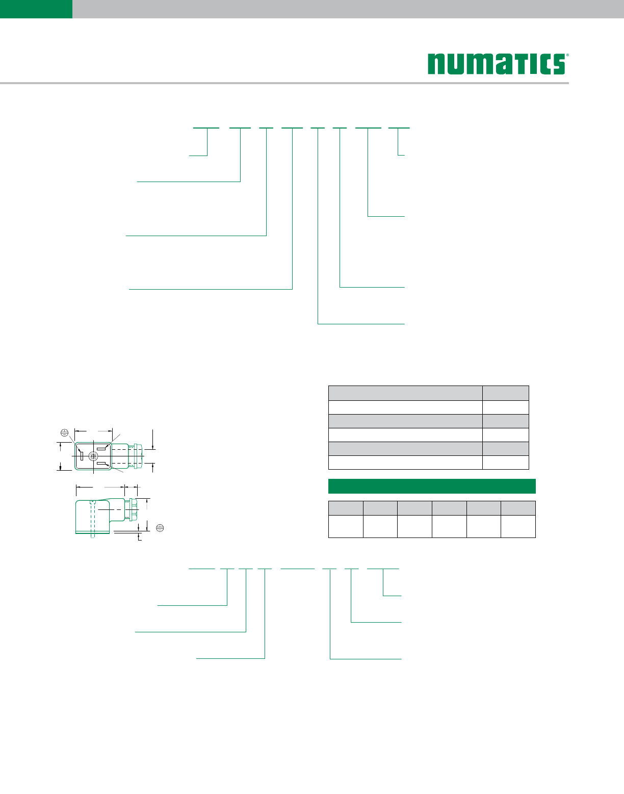
Plug connector assemblies
Per DIN Spec. NO 43650. Accepts cable diameter 0.240 to 0.310
11 mm Industry Standard DIN Form B
Dimensions: Inches (mm)
A B C D E F
1.12
(28.4)
0.83
(21.1)
1.57
(39.9)
0.40
(10.2)
1.10
(27.9)
0.06
(1.5)
How to Order
Valves
Information subject to change without notice. For ordering information or regarding your local sales office visit www.numatics.com.
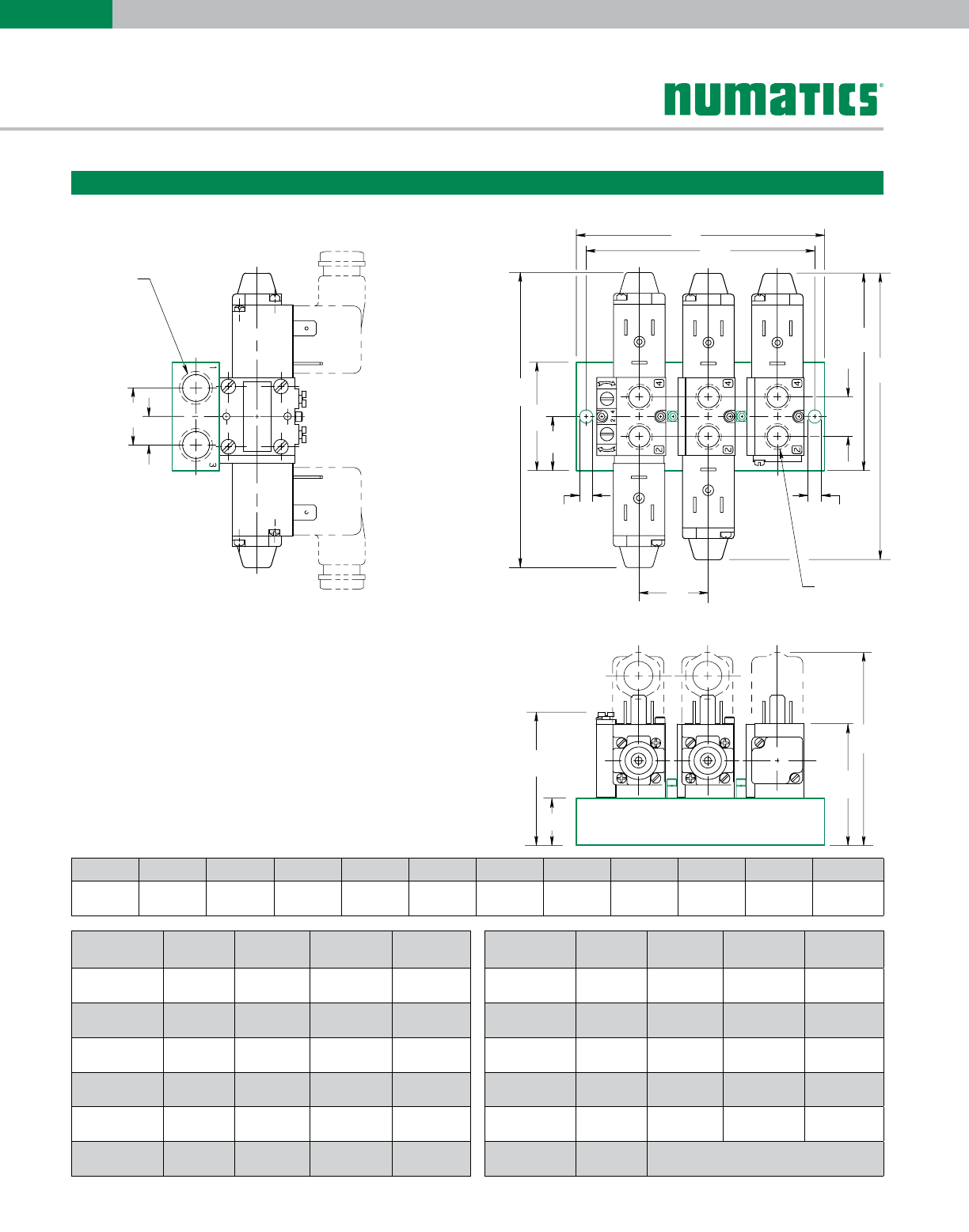
5
L01
SERIES
J
K
L
M
A
A
BC
F
E
D
G
H
I
A
A
J
K
L
M
A
A
A
A
BC
F
E
D
G
I
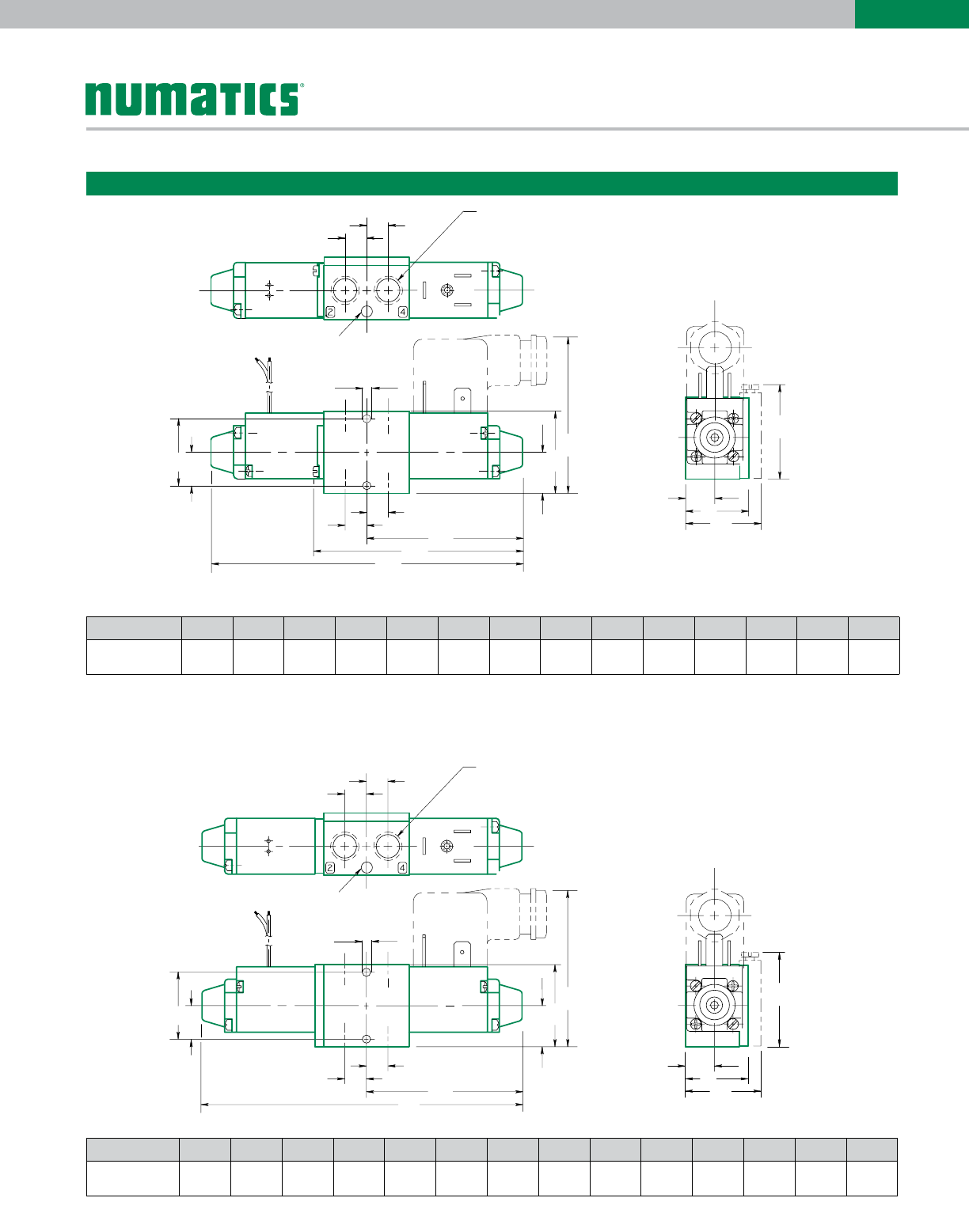
1/8 NPTF or
G 1/8 Ports (4)
Single Solenoid L01SA4
Double Solenoid L01SS4
Speed control
shown in phantom
1/8 NPTF or
G 1/8 Ports (4)
Speed control
shown in phantom
7/64 dim.
7/64 dim.
N
N
Valve 2 Position
Valve 3 Position
Dimensions: Inches (mm)
A B C D E F G H I J K L M N
3 position valves 0.31
(7.9)
0.97
(24.6)
0.49
(12.4)
0.59
(15.0)
1.19
(30.2)
2.33
(59.2)
2.37
(60.2)
3.14
(79.8)
4.86
(123.4)
1.35
(34.3)
0.42
(10.7)
0.90
(22.9)
1.08
(27.4)
0.11
(2.8)
A B C D E F G H I J K L M N
2 position valves 0.31
(7.9)
0.97
(24.6)
0.49
(12.4)
0.59
(15.0)
1.19
(30.2)
2.33
(59.2)
2.30
(58.4)
3.14
(79.8)
4.60
(116.8)
1.35
(34.3)
0.42
(10.7)
0.90
(22.9)
1.08
(27.4)
0.11
(2.8)
Information subject to change without notice. For ordering information or regarding your local sales office visit www.numatics.com.
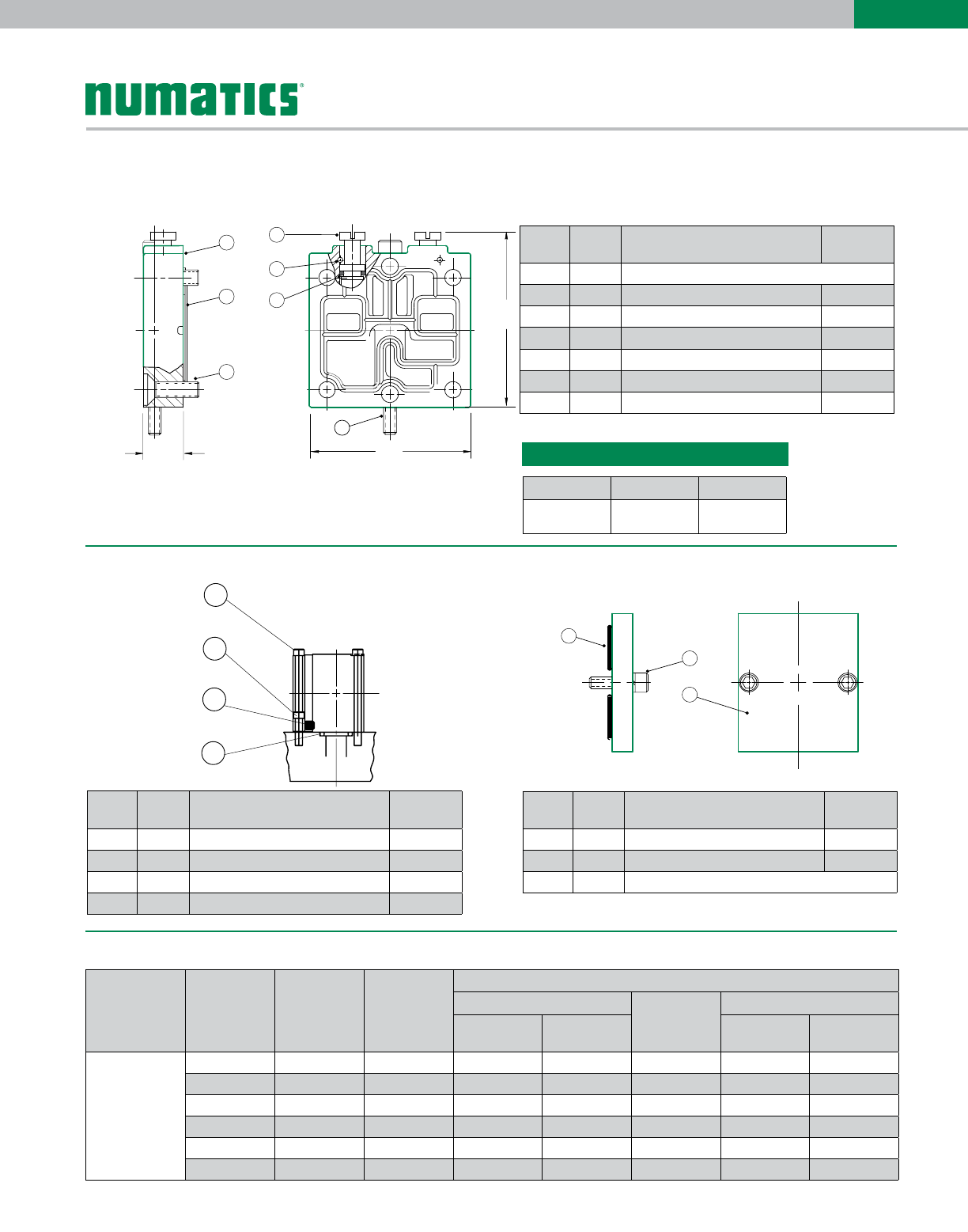
6
L01
SERIES
A
B
1/8 NPTF
orG1/8
Cylinder Ports
1/4 NPTF or
G 1/4 ports
(2)
(Both Ends)
F
G
CD
H
I
J
M
N
O
P
L
E
KK
3-position L01SS5
2-position L01SS4
Dimensions: Inches (mm)
Manifold Assembly
Common Supply and Exhaust
Manifold #
Stations Dim A Dim B 1/4 NPTF G 1/4
2 Stations 2.84
(72.1)
2.53
(64.3) 106-822 106-833
3 Stations 3.94
(100)
3.63
(92.2) 106-823 106-834
4 Stations 5.03
(127.7)
4.72
(119.9) 106-824 106-835
5 Stations 6.13
(155.7)
5.82
(147.8) 106-825 106-836
6 Stations 7.23
(183.6)
6.91
(177.5) 106-826 106-837
7 Stations 8.23
(211.3)
8.01
(203.5) 106-827 106-838
Manifold #
Stations Dim A Dim B 1/4 NPTF G 1/4
8 Stations 9.42
(239.3)
9.11
(231.4) 106-828 106-839
9 Stations 10.51
(267.0)
10.20
(259.1) 106-829 106-840
10 Stations 11.61
(294.9)
11.30
(287.0) 106-830 106-841
11 Stations 12.71
(322.8)
12.39
(314.7) 106-831 106-842
12 Stations 13.80
(350.5)
13.49
(342.6) 106-832 106-843
Mounting Kit 239-582 Order (1) mounting kit for each station on the
manifold. Includes all studs, seals & screws.
A B C D E F G H I J K L
See table
below
See table
below
0.91
(23.1)
0.45
(11.4)
4.86
(123.9)
1.69
(42.9)
0.84
(21.3)
0.62
(15.7)
3.14
(79.7)
4.60
(116.8)
0.20
(5.1)
1.10
(27.9)
Information subject to change without notice. For ordering information or regarding your local sales office visit www.numatics.com.
7
L01
SERIES
Solenoid Capsule Assemblies (Flush Non-Locking Override)
Includes solenoid and end cap assembly + screws and gaskets.
Speed Control Kit - Side Mounted 239-581
1
AB
C
2
4
3
5
6
7
Parts List
Dimensions: Inches (mm)
A B C
0.30
(7.6)
1.22
(31.0)
1.35
(34.3)
Mounting Kit 239-582 Blank Station Plate Kit 239-583
1
2
2
4
1
2
3
Parts List Parts List
Port
Type
Part.
No. Part Name Part No.
1 * 1Speed Control Body (not sold separately)
2 * 1 Gasket 113-414
3 * 4Screw Assembly 127-671
4 * 2Metering Screw 118-166
5 * 2 Pin 131-220
6 * 2O-Ring Seal 126-163
7 * 1 Screw 127-670
Port
Type
Part.
No. Part Name Part No.
1 2 Screw 127-670
2 1 Screw 127-669
3 1 Mounting Stud 125-560
4 2 O-Ring 126-107
Port
Type
Part.
No. Part Name Part No.
1 2 O-Ring Seal 126-106
2 2 Screw 127-669
3 1 Blank Station Plate (not sold separately)
*Indicates parts included in kit
Override Type Valve Function Wiring Option 12/14 End
Voltage
AC
24/50-60
DC
100-115/50
110-120/60
200-230/50
220-240/60 12 VDC 24 VDC
Flush non-
locking override
(standard)
2 Stations Hardwired 12/14 237-952 237-953 237-954 236-102 236-103
2 Stations DIN plug-in 12/14 237-961 237-962 237-963 236-126 236-127
3 Stations Hardwired 12 end 237-993 237-992 237-994 236-154 236-155
3 Stations Hardwired 14 end 237-990 237-989 237-991 236-108 236-109
3 Stations DIN plug-in 12 end 237-1011 237-1010 237-1012 236-166 236-167
3 Stations DIN plug-in 14 end 237-1008 237-1007 237-1009 236-132 236-133
Information subject to change without notice. For ordering information or regarding your local sales office visit www.numatics.com.
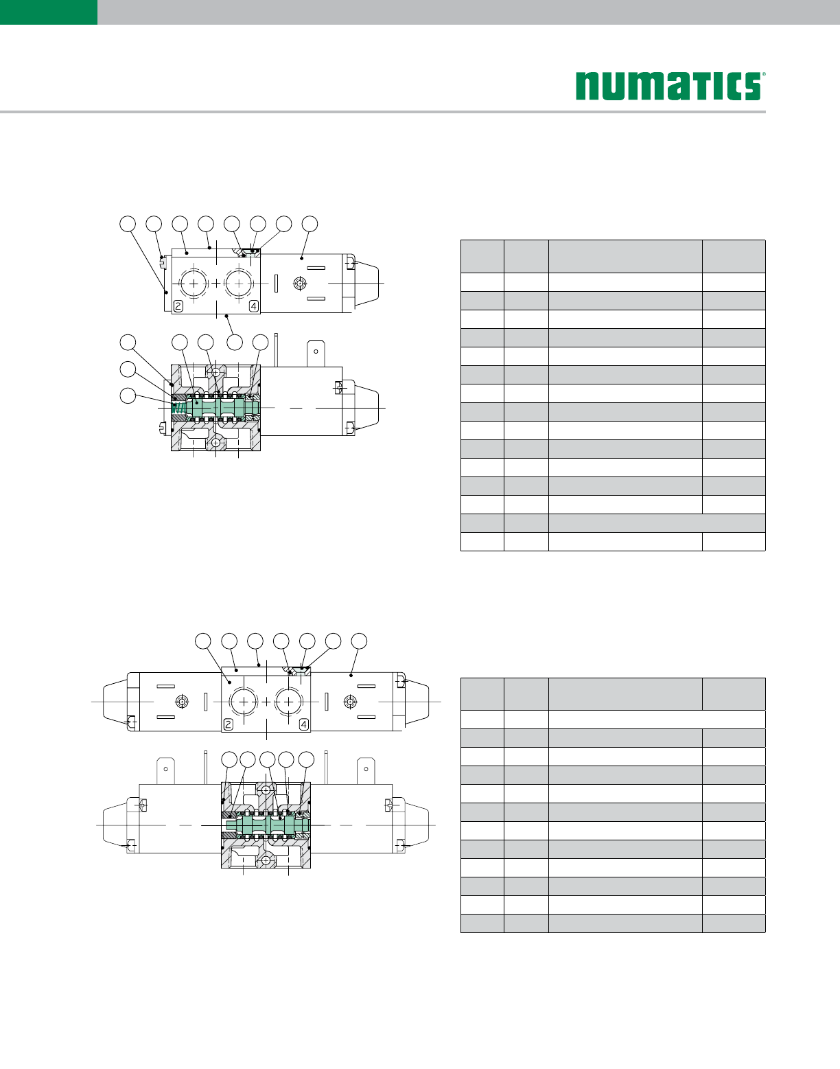
8
L01
SERIES
3 4 5 6 7 8
12 14
10
9
21
1511 13
2 3 4 5 6 7
8
1
119 10 11
3 4 5 6 7 8
12 14
10
9
21
1511 13
2 3 4 5 6 7
8
1
119 10 11
Valve Service Kits and Parts
Kit No. L01-K1* (For Model L01SA4)
Parts List
Parts List
*Indicates parts included in service kit. **Spool and sleeve assemblies sold as precision matched set and include (6) #126-133 seals; spools are not interchangeable.
Kit No. L01-K1* (For Model L01SS4)
Port
Type
Part.
No. Part Name Part No.
1 1 Spring Cover 104-199
2 2 Screw 127-260
3 1 Top Plate 105-313
4 1 Nameplate 122-571
5* 1 Gasket 113-414
6 4 Screw 127-604
7 4 Lockwasher 128-316
8 1 Solenoid Assembly (12/14) See p. 7
9* 1 Spring 115-203
10* 1 Bumper 114-130
11* 2 O-Ring Seal 126-134
12 1 Sleeve Assembly w/Seals 209-278
13* 6 Seals 126-133
14 1 Vlave Body (not sold separately)
15* 1 Detent Body 110-109
Port
Type
Part.
No. Part Name Part No.
1 1 Valve Body (not sold separately)
2 1 Top Plate 105-313
3 1 Nameplate 122-571
4* 1 Gasket 113-414
5 4 Screw 127-604
6 4 Lockwasher 128-316
7 2 Solenoid Assembly (12/14) See p. 7
8* 2 O-Ring Seal 126-134
9* 1 Bumper 114-130
10 1 Sleeve Assembly w/Seals 209-278
11* 6 Seals 126-133
12* 1 Detent Assembly 210-111
Information subject to change without notice. For ordering information or regarding your local sales office visit www.numatics.com.
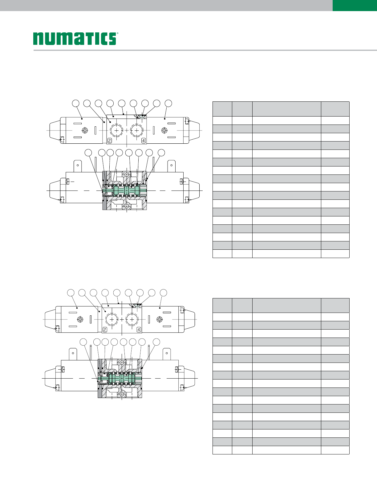
9
L01
SERIES
Valve Service Kits and Parts
Kit No. L01-K3* (For Model L01SS5)
Kit No. L01-K3* (For Model L01SS6)
4 5 6 7 8 9
12
3
14
13
2
11 16 1710
1
15
4 5 6 7 8 9
12
3
1513
2
11 16 1710
1
14
4 5 6 7 8 9
12
3
14
13
2
11 16 1710
1
15
4 5 6 7 8 9
12
3
1513
2
11 16 1710
1
14
*Indicates parts included in service kit. **Spool and sleeve assemblies sold as precision matched set and include (6) #126-133 seals; spools are not interchangeable.
Parts List
Parts List
Port
Type
Part.
No. Part Name Part No.
1 1 Solenoid Assembly (12 End) See p. 7
2 1 Adaptor 119-343
3 1 Valve Body (not sold separately)
4 1 Top Plate 105-313
5 1 Nameplate 122-571
6* 1 Gasket 113-414
7 4 Screw 127-604
8 4 Lockwasher 128-316
9 1 Solenoid Assembly (14 End) See p. 7
10* 1 Spring Retainer 116-396
11* 1 Spacer 116-397
12* 1 Spring 115-291
13* 1 Spring Retainer 116-395
14 1 Sleeve Assembly w/Seals **209-373
15* 6 Seals 126-133
16* 1 Bumper 114-171
17* 3 O-Ring Seals 126-134
Port
Type
Part.
No. Part Name Part No.
1 1 Solenoid Assembly (12 End) See p. 7
2 1 Adaptor 119-343
3 1 Valve Body (not sold separately)
4 1 Top Plate 105-313
5 1 Nameplate 122-571
6* 1 Gasket 113-414
7 4 Screw 127-604
8 4 Lockwasher 128-316
9 1 Solenoid Assembly (14 End) See p. 7
10* 1 Spring Retainer 116-396
11* 1 Spacer 116-397
12* 1 Spring 115-291
13* 1 Spring Retainer 116-395
14 1 Sleeve Assembly w/Seals 209-374**
15* 6 Seals 126-133
16* 1 Bumper 114-171
17* 3 O-Ring Seals 126-134

World Class Supplier of Pneumatic Components
Numatics, Inc. | Tel (248) 596-3200 | www.numatics.com | email: insidesales@numatics.com
LT-L01Series Rev 06/12
10M-IPC-01/09
© Numatics Inc. 2012 - 2013
Numatics® is registered in the United States and elsewhere
World Headquarters
USA Numatics, Incorporated
46280 Dylan Drive
Novi, Michigan 48377
P: 248-596-3200
F: 248-596-3201
Canada Numatics, Ltd
P: 519-758-2700
F: 519-758-5540
Brazil Ascoval Ind.e Comercio Ltda
P: (55) 11-4208-1700
F: (55) 11-4195-3970
México - Ascomatica SA de CV
P: 52 55 58 09 56 40 (DF y Area metropolitana)
P: 01 800 000 ASCO (2726) (Interior de la República)
F: 52 55 58 09 56 60
