Flow Oriental Motors Dsc Series Ac Motor Speed Control System 1505487622 User Manual
Oriental Motors Dsc Series Ac Motor Speed Control System-1505487622 ORIENTAL_MOTORS_DSC_SERIES_AC_MOTOR_SPEED_CONTROL_SYSTEM-1505487622 ORIENTAL_MOTORS_DSC_SERIES_AC_MOTOR_SPEED_CONTROL_SYSTEM-1505487622 ORIENTAL MOTORS DSC SERIES AC MOTOR SPEED CONTROL SYSTEM Motors s development assets-flotronics
2017-10-06
User Manual: Flow Oriental Motors Dsc Series Ac Motor Speed Control System-1505487622 ORIENTAL_MOTORS_DSC_SERIES_AC_MOTOR_SPEED_CONTROL_SYSTEM-1505487622 ORIENTAL MOTORS DSC SERIES AC MOTOR SPEED CONTROL SYSTEM Motors s production assets-flotronics
Open the PDF directly: View PDF ![]() .
.
Page Count: 38
D-138
D-138
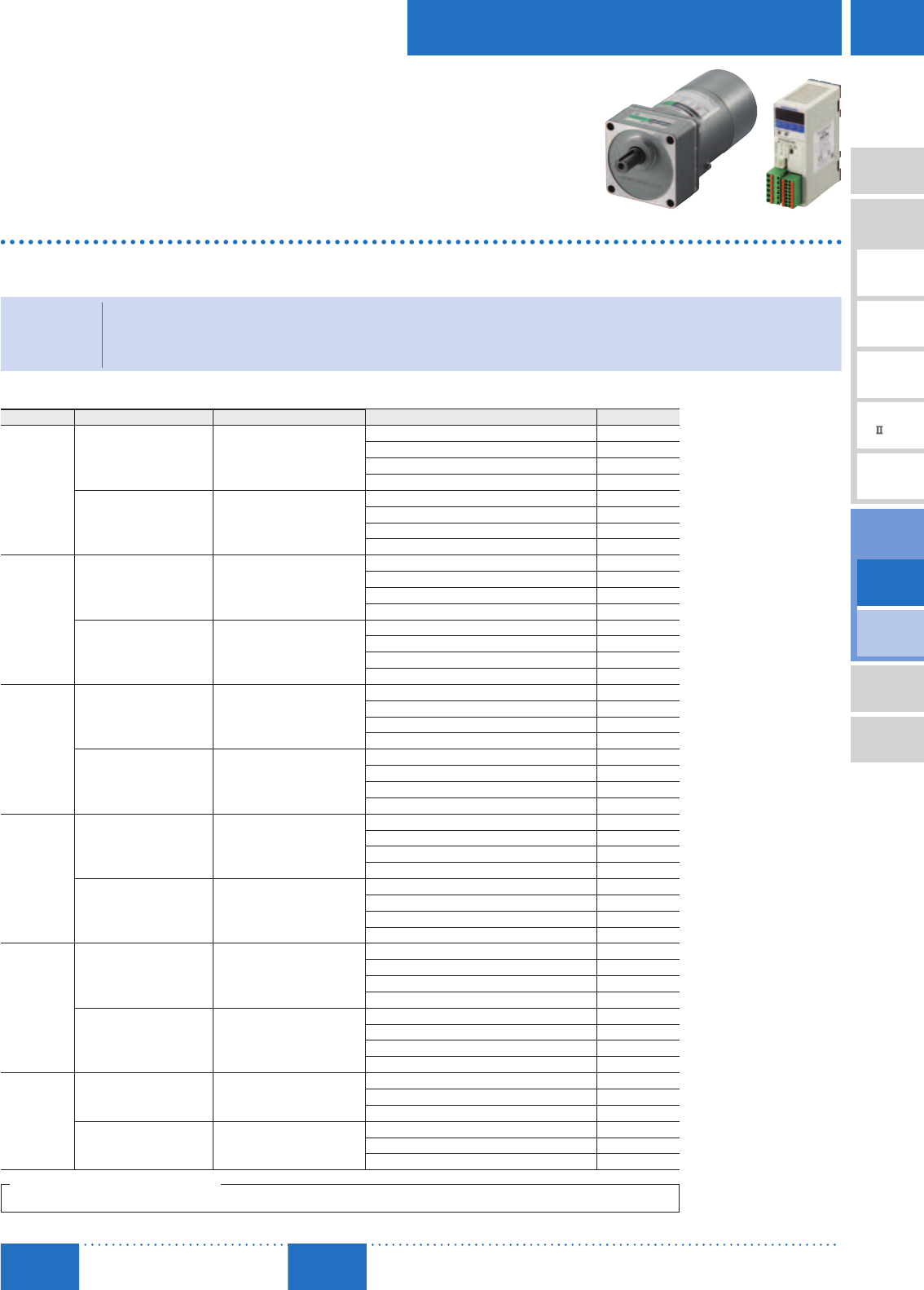
ORIENTAL MOTOR GENERAL CATALOG
2015/2016
Standard Type
Parallel Shaft/
Round Shaft
Electromagnetic
Brake Type
Parallel Shaft
Speed Control Motor and Controller Package
DSC Series
For detailed information about regulations and standards, please see the Oriental
Motor website.
View Expanded Product Information,
Specifications, CAD, Accessories & more online.
Visit www.orientalmotor.com/catalog or use
the QR code and select "DSC Series".
•
A high-reliability closed loop control speed control
package.
•
High performance, with easy installation and simple data
setting. The display and digital setting features are
built-in, making it even easier to use.
•
An entry level speed control package that is both
reasonably priced and compact.
•
The electromagnetic brake type can be operated
vertically.
The DSC Series features are AC motors and speed controllers
that utilize Oriental Motor's exclusive technology. They provide
high reliability with closed loop control, and because the
phase control circuit has been digitized, the size of the speed
controller has been reduced.
<Additional Information>
•Technical reference ➜ Page H-1
•Regulations & Standards ➜ Page I-2
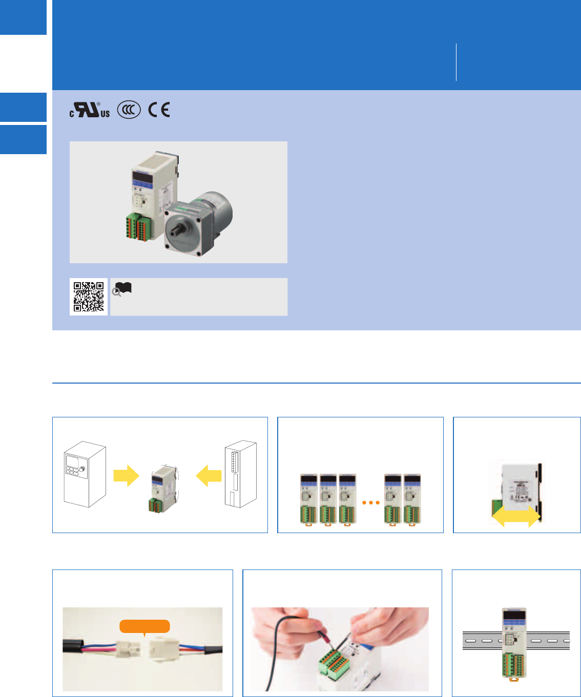
■Features
Easy Setting, More Control, Less Space
Compact Side-by-Side Installation Saves
Space
Slim Body Control Box
The volume is 63% smaller than a general inverter. The body width is 35 mm (1.38 in.),
and even when using multiple speed
controllers, the installation is compact
because they can be installed side by side.
Depth is 90 mm (3.54 in.).
Can be installed in slim body
control cabinets.
DSC Series
General Inverter
63% reduction 31% reduction
Conventional Product
Speed Controller
70 mm
(2.76 in.)
100 mm
(3.94 in.)
35 mm
(1.38 in.)
90 mm (3.54 in.)
Connecting the Motor and Driver is
Easy Using a Connector
Screwless I/O Wiring Requires No Crimping
or Screwing
Easy DIN Rail Installation
Wiring the speed controller and motor together
uses a connector, so installation and removal
are easy.
No need for soldering or crimping tools, and no
torque management for screws necessary. Reduces
wiring time and maintenance.
The speed controller can be
installed directly on the DIN rail.
Click!
D-139
Brushless Motors/AC Speed Control Motors
D-139
Brushless
Motors
Overview,
Product
Series
AC Input
BMU
AC Input
BLE
AC Input
BLF
AC Input
BX
DC Input
BLH
DSC
BHF
AC Speed
Control
Motors
Accessories
Installation
CAD Data
Manuals www.orientalmotor.com Technical
Support TEL: (800) 468-3982
E-mail: techsupport@orientalmotor.com
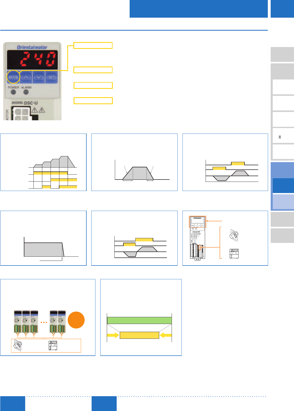
Simple User Interface
Speed and Other Settings are Shown and can be Entered Directly
Monitoring Mode
Data Mode
Real-time monitor for speed
(Motor, gear shaft, conveyor speed), alarms,
warnings, I/O status monitor
Speed setting
Parameter Mode
Set I/O assignments and parameters
Test Mode
Test operation without data setting is possible.
An operation lock can prevent accidental operation.
Speed Control (4 speeds) Acceleration/Deceleration Bi-Directional Operation
4 units of operating data can be set, and can
be switched with I/O during operation.
Makes the motor movement at start/stop
smoother. It is possible to set acceleration/
deceleration differently for each of the
4-speed data units.
Performs the operation according to the
command for rotation direction.
ON
OFF
ON
OFF
ON
OFF
FWD Input
No.0
No.1
No.2
No.3
M1 Input
M0 Input
Motor Movement
Time
Acceleration
Acceleration Time Deceleration Time
Deceleration
Motor Speed
ON
ON
CCW
CW
REV Input
FWD Input
Motor Speed
Instantaneous Stop Instantaneous Bi-Directional
Operation
External Speed Setting Input is
Possible
Stops the operating motor instantaneously.
(Short cycle run/stop conditions can be
created)
Instantaneously switches the rotation
direction of the motor while operating.
(Short cycle change conditions can be
created)
(2) External speed potentiometer
Included or accessory
(3) External DC voltage
0∼5 VDC or 0∼10 VDC
(1) Setting using operation key
External
speed
remote
setting
Time
Instantaneous Stop
Motor Speed
REV Input
FWD Input
Motor Speed
Parallel-Motor Operation (20 Units Max.) Speed Range Control
A single external speed potentiometer can
operate a maximum of 20 units in parallel.
Fine adjustment of each motor's speed can
be performed by changing the controller's
parameters.
It is possible to limit the speed setting in
advance with the speed range.
or
Up to
20
Motors
External
Speed
Potentiometer
External DC Voltage
0∼5 VDC
0∼10 VDC
1600 r/min90
300 1000
Lower Limit Change Upper Limit Change
D-140
D-140 AC Speed Control Motors/DSC Series
ORIENTAL MOTOR GENERAL CATALOG
2015/2016
Standard Type
Parallel Shaft/
Round Shaft
Electromagnetic
Brake Type
Parallel Shaft
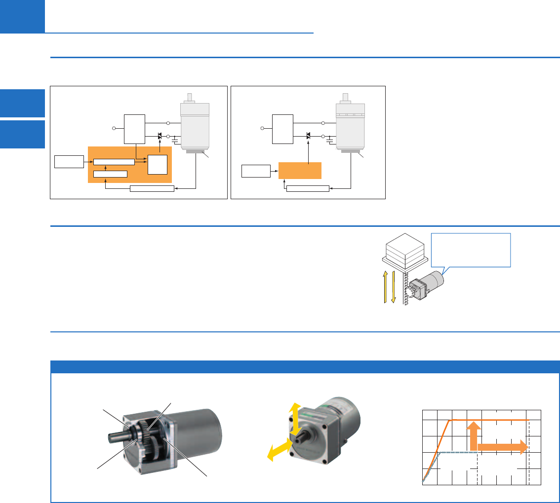
Speed Control Using Closed Loop Control
Speed is always monitored by the tachogenerator built into the AC motor.
The actual speed is controlled to match the speed setting, even when the load fluctuates.
Triac
AC Power
Supply
Zero Cross
Detection
Circuit
Speed Command
Component
Speed Detection Circuit
Digital Circuit
Tachogenerator
Analog Circuit
Speed Calculation
Trigger
Generator
Triac
AC Power
Supply
Zero Cross
Detection
Circuit
Comparison Calculator
Speed Command
Component
Speed Detection Circuit
Tachogenerator
Conventional Product
Analog Circuit (Block diagram)
DSC Series
Digital Circuit (Block diagram)
Speed regulation±1% (Reference value)
Digitalization of Circuits
Most of the analog circuits that were used in the past have
been replaced with software, which is now run by the CPU,
and circuit components have been vastly reduced. This
has drastically reduced the size as well as the number of
circuit components. In addition, due to this switch to digital
processing, it is possible to make the deviation for the
speed command and speed detection values almost 0, and
speed regulation has been improved from −5% to ±1%✽.
✽0∼permissible torque when at 1000 r/min
Use of a High Permissible Torque, High Strength Gearhead
Utilizes a gearhead that excels in both permissible torque and strength.
Special side panels in the gearhead have increased case rigidity, and heat processing (carburization) has increased the strength of the gears.
Parallel Shaft Combination Type
[Internal Gearhead Structure]
Permissible Radial Load 450 N (101 lb.)
[10 mm (0.39 in.) from the end of the output shaft]
Permissible Axial Load 100 N (22 lb.)
Oil Seal
Large-Diameter
Bearing Side Panel
Carburized Shaft and Gears Permissible Radial Load
Permissible Axial Load
50 100 150 200 250 300 350 400
0
4 (35)
8 (70)
12 (106)
16 (141)
Gear Ratio
Permissible Torque [N·m (lb-in)]
Permissible torque
has been doubled
Increased variety
for the high gear
ratio product lineup
Oriental Motor
Conventional
Product
DSC Series
DSC Series
Permissible Torque
16 N·m (141 lb-in)
Oriental Motor Conventional
Product 4GN-K
Permissible Torque
8 N·m (70 lb-in)
[For Geared Type with 80 mm (3.15 in.) Frame Size]
Speed control in vertical operation is possible through deceleration
control. (For details on deceleration control and driving conditions
while using deceleration control, refer to page D-158.)
Speed Control Range
[50 Hz]
300∼1400 r/min
[60 Hz]
300∼1600 r/min
No regeneration
unit required
Vertical Operation is Possible with Electromagnetic Brake Type
D-141
Brushless Motors/AC Speed Control Motors
D-141
Brushless
Motors
Overview,
Product
Series
AC Input
BMU
AC Input
BLE
AC Input
BLF
AC Input
BX
DC Input
BLH
DSC
BHF
AC Speed
Control
Motors
Accessories
Installation
CAD Data
Manuals www.orientalmotor.com Technical
Support TEL: (800) 468-3982
E-mail: techsupport@orientalmotor.com
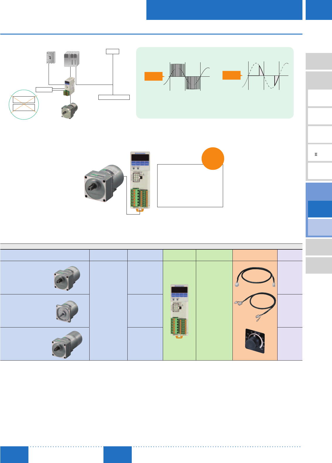
High Reliability
Low Noise Gives Peace of Mind, and System Configuration is Simple
Circuit Breaker
or Earth Leakage
Circuit Breaker
Thermal protector provides
overheat protection
Speed Controller
Short circuit
shutoff
24 VDC
Sensors and other devices
PLC
Capacitor
Has overload
protection and
overheat protection
output
Inverter + Three-Phase Motor DSC Series
Controls the voltage and frequency
1 cycle performs 300 switchings
[Condition] Carrier frequency: 15 kHz
Setting frequency: 50 Hz
Controls the voltage
1 cycle performs 2 switchings
[Conditions] Power supply
frequency: 50 Hz
Voltage
Time
Voltage
Time
[Phase control]
[PWM control]
Lots of
noise
Little
noise
Not necessary
Solid state relay
Circuit protector
Alarm Output Increases Reliability
Thanks to the closed loop control, feedback on the motor status is provided to the controller in real-time. An alarm signal is output when an
abnormality, such as motor lock due to overload, occurs and the supply of power to the motor is stopped.
Alarm Details
Motor Overheat
Motor Lock
Overspeed
EEPROM (Saved data error)
Operation Stop During Initialization
External Stop
Saves a
History
of up to 9
Alarms
■Product Line
The motor, gearhead, speed controller, connection cables [3 m (9.8 ft.)] and external speed potentiometers are delivered as one package.
Unit
Motor Output Power Max. Permissible
Torque Speed Controller Power Supply
Voltage Included Unit Price
Range
Standard Type
Parallel Shaft
Combination Type
➜ Page D-143
6 W (1/125 HP)
15 W (1/50 HP)
25 W (1/30 HP)
40 W (1/19 HP)
60 W (1/12 HP)
90 W (1/8 HP)
40 N·m (350 lb-in)
Single-Phase
110/115 VAC
Single-Phase
220/230 VAC
Connection Cable
3 m (9.8 ft.)
$294.00
∼
$460.00
Standard Type
Round Shaft Type
➜ Page D-143
0.73 N·m (6.4 lb-in)
3 m (9.8 ft.)
External Speed Potentiometer
$237.00
∼
$312.00
Electromagnetic Brake Type
Parallel Shaft
Combination Type
➜ Page D-157
40 N·m (350 lb-in)
$379.00
∼
$600.00
D-142
D-142 AC Speed Control Motors/DSC Series
ORIENTAL MOTOR GENERAL CATALOG
2015/2016
Standard Type
Parallel Shaft/
Round Shaft
Electromagnetic
Brake Type
Parallel Shaft
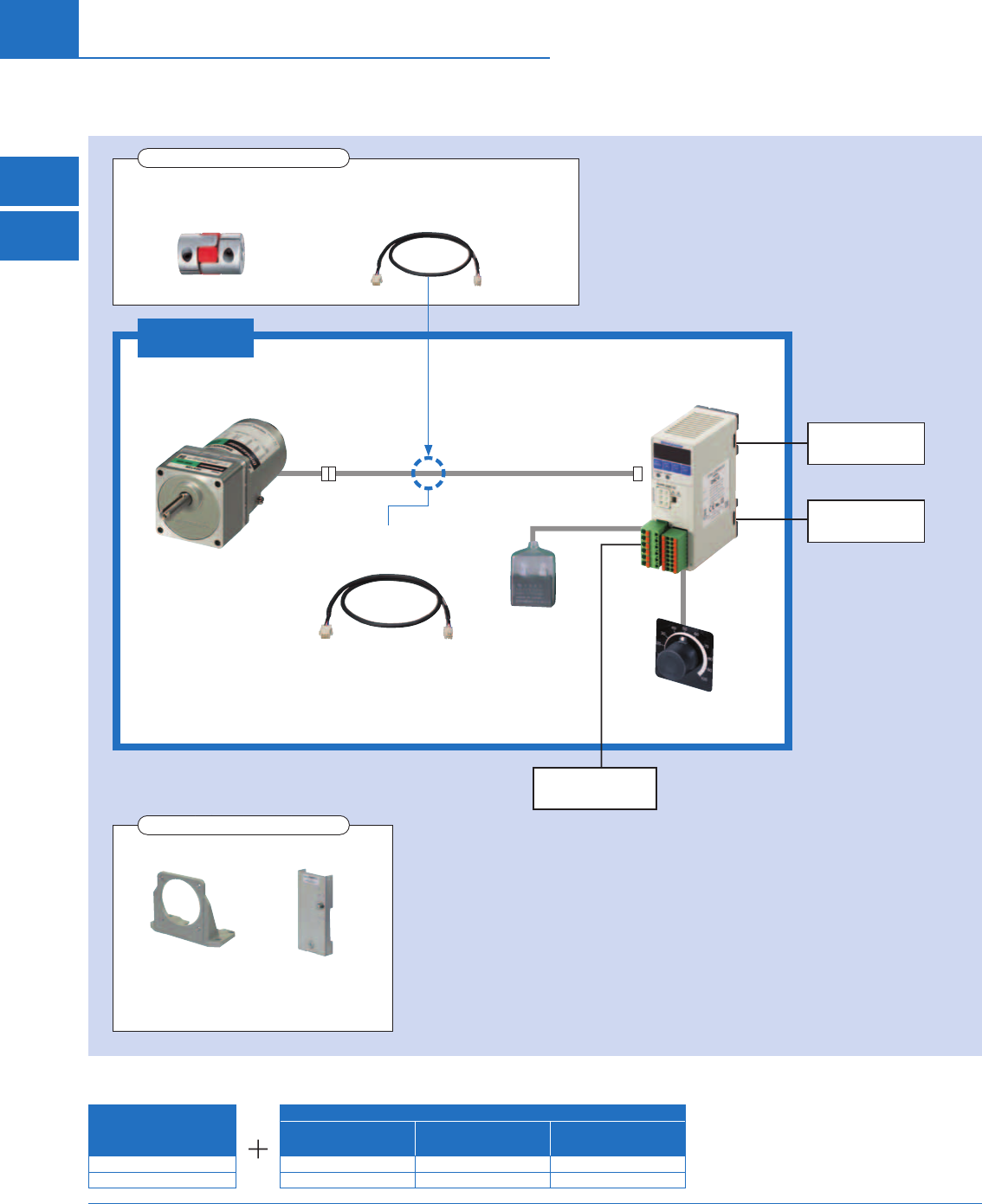
■System Configuration
Parallel Shaft Combination Type
Example of System Confi guration
DSC Series
Sold Separately
Connection Cable
[5 m (16.4 ft.)] Mounting Bracket Flexible Coupling
DSCI425UA-25A-3V CC05SC SOL4UAF MCL40F10F10
$321.00 $68.00 $27.00 $76.00
The system configuration shown above is an example. Other combinations are also available.
✽Not supplied.
DSC Series
Flexible Couplings
➜ Page D-190
Connection Cables, Flexible Connection Cables
➜ Page D-186
Accessories (Sold separately)
Mounting Brackets
➜Page D-190
Capacitor Mounting
Brackets
➜Page C-208
Accessories (Sold separately)
Programmable
Controller✽
AC Power Supply
(Main power supply)
Speed Controller
Capacitor and
Capacitor Cap
(Included)
Connection Cable
(Included)
Combination Type
(Motor and gearhead)
External Speed
Potentiometers
(Included)
24 VDC Power
Supplies for Control
D-143
Brushless Motors/AC Speed Control Motors
D-143
Brushless
Motors
Overview,
Product
Series
AC Input
BMU
AC Input
BLE
AC Input
BLF
AC Input
BX
DC Input
BLH
DSC
BHF
AC Speed
Control
Motors
Accessories
Installation
CAD Data
Manuals www.orientalmotor.com Technical
Support TEL: (800) 468-3982
E-mail: techsupport@orientalmotor.com
Standard Type
Parallel Shaft Combination Type
Round Shaft Type
■Product Line
Combination Type
Delivered with the motor and gearhead pre-assembled.
The combination of motor and gearhead can be changed, or purchased separately. In addition, the gearhead can be
removed and the assembly position can be changed in 90° increments.
Parallel Shaft Combination Type
Output Power Power Supply Voltage Product Name Gear Ratio List Price
6 W
(1/125 HP)
Single-Phase
110/115 VAC DSCI26UA-□A-3V
5, 6, 7.5, 9, 12.5, 15, 18 $294.00
25, 30, 36 $300.00
50, 60, 75, 90, 100, 120, 150, 180 $307.00
250, 300, 360 $353.00
Single-Phase
220/230 VAC DSCI26EC-□A-3V
5, 6, 7.5, 9, 12.5, 15, 18 $297.00
25, 30, 36 $303.00
50, 60, 75, 90, 100, 120, 150, 180 $310.00
250, 300, 360 $356.00
15 W
(1/50 HP)
Single-Phase
110/115 VAC DSCI315UA-□A-3V
5, 6, 7.5, 9, 12.5, 15, 18 $305.00
25, 30, 36 $311.00
50, 60, 75, 90, 100, 120, 150, 180 $318.00
250, 300, 360 $362.00
Single-Phase
220/230 VAC DSCI315EC-□A-3V
5, 6, 7.5, 9, 12.5, 15, 18 $308.00
25, 30, 36 $314.00
50, 60, 75, 90, 100, 120, 150, 180 $321.00
250, 300, 360 $365.00
25 W
(1/30 HP)
Single-Phase
110/115 VAC DSCI425UA-□A-3V
5, 6, 7.5, 9, 12.5, 15, 18 $315.00
25, 30, 36 $321.00
50, 60, 75, 90, 100, 120, 150, 180 $328.00
250, 300, 360 $375.00
Single-Phase
220/230 VAC DSCI425EC-□A-3V
5, 6, 7.5, 9, 12.5, 15, 18 $319.00
25, 30, 36 $325.00
50, 60, 75, 90, 100, 120, 150, 180 $332.00
250, 300, 360 $379.00
40 W
(1/19 HP)
Single-Phase
110/115 VAC DSCI540UA-□A-3V
5, 6, 7.5, 9, 12.5, 15, 18 $345.00
25, 30, 36 $352.00
50, 60, 75, 90, 100, 120, 150, 180 $359.00
250, 300 $437.00
Single-Phase
220/230 VAC DSCI540EC-□A-3V
5, 6, 7.5, 9, 12.5, 15, 18 $349.00
25, 30, 36 $356.00
50, 60, 75, 90, 100, 120, 150, 180 $363.00
250, 300 $441.00
60 W
(1/12 HP)
Single-Phase
110/115 VAC DSCI560UA-□A-3V
5, 6, 7.5, 9, 12.5, 15, 18 $400.00
25, 30, 36, 50, 60, 75, 90, 100 $411.00
120, 150, 180 $421.00
250, 300 $455.00
Single-Phase
220/230 VAC DSCI560EC-□A-3V
5, 6, 7.5, 9, 12.5, 15, 18 $405.00
25, 30, 36, 50, 60, 75, 90, 100 $416.00
120, 150, 180 $426.00
250, 300 $460.00
90 W
(1/8 HP)
Single-Phase
110/115 VAC DSCI590UA-□A-3V
5, 6, 7.5, 9, 12.5, 15, 18 $420.00
25, 30, 36, 50, 60 $440.00
75, 90, 100, 120, 150, 180 $450.00
Single-Phase
220/230 VAC DSCI590EC-□A-3V
5, 6, 7.5, 9, 12.5, 15, 18 $425.00
25, 30, 36, 50, 60 $445.00
75, 90, 100, 120, 150, 180 $455.00
The following items are included with each product.
Motor, Gearhead, Speed Controller, Capacitor, Capacitor Cap, Installation Screws, Parallel Key, Connection Cable, External Speed Potentiometer, Operating Manual
Parallel Shaft Combination Type
A number indicating the gear ratio is entered where the box □ is located within the product name.

D-144
D-144 AC Speed Control Motors/DSC Series
ORIENTAL MOTOR GENERAL CATALOG
2015/2016 Page
Features D-138 / System Configuration D-142 / Product Line D-143 / Specifications D-145 / Characteristics D-149
Dimensions D-150 / Connection and Operation D-171 / Motor and Controller Combinations D-156
Standard Type
Parallel Shaft/
Round Shaft
Electromagnetic
Brake Type
Parallel Shaft
Round Shaft Type
Output Power Power Supply Voltage Product Name List Price
6 W
(1/125 HP)
Single-Phase
110/115 VAC DSCI26UA-A-3V $237.00
Single-Phase
220/230 VAC DSCI26EC-A-3V $240.00
15 W
(1/50 HP)
Single-Phase
110/115 VAC DSCI315UA-A-3V $243.00
Single-Phase
220/230 VAC DSCI315EC-A-3V $246.00
25 W
(1/30 HP)
Single-Phase
110/115 VAC DSCI425UA-A-3V $252.00
Single-Phase
220/230 VAC DSCI425EC-A-3V $256.00
40 W
(1/19 HP)
Single-Phase
110/115 VAC DSCI540UA-A-3V $270.00
Single-Phase
220/230 VAC DSCI540EC-A-3V $274.00
60 W
(1/12 HP)
Single-Phase
110/115 VAC DSCI560UA-A-3V $288.00
Single-Phase
220/230 VAC DSCI560EC-A-3V $293.00
90 W
(1/8 HP)
Single-Phase
110/115 VAC DSCI590UA-A-3V $307.00
Single-Phase
220/230 VAC DSCI590EC-A-3V $312.00
The following items are included with each product.
Motor, Speed Controller, Capacitor, Capacitor Cap, Connection Cable, External Speed Potentiometer,
Operating Manual
■Product Number
DSC I 4 25 UA - 50A - 3 V
①②③④ ⑤ ⑦⑧⑥
①Series Name DSC: DSC Series
②Motor Type I: Induction Motor
③Motor Frame Size 2: 60 mm (2.36 in.) 3: 70 mm (2.76 in.) 4: 80 mm (3.15 in.) 5: 90 mm (3.54 in.)
④Output Power (W) (Example) 25: 25 W (1/30 HP)
⑤Power Supply Voltage UA: Single-Phase 110/115 VAC EC: Single-Phase 220/230 VAC
⑥Gear Ratio/Shaft Type Number: Gear Ratio for Combination Types A: Round Shaft Type
⑦Connection Cable
(Included) 3: Length of the included connection cable is 3 m (9.8 ft.)
⑧External Speed Potentiometer
(Included) V: Includes external speed potentiometer
D-145
Brushless Motors/AC Speed Control Motors
D-145
Brushless
Motors
Overview,
Product
Series
AC Input
BMU
AC Input
BLE
AC Input
BLF
AC Input
BX
DC Input
BLH
DSC
BHF
AC Speed
Control
Motors
Accessories
Installation
CAD Data
Manuals www.orientalmotor.com Technical
Support TEL: (800) 468-3982
E-mail: techsupport@orientalmotor.com
■Specifications – Continuous Rating
Single-Phase 110/115 VAC, Single-Phase 220/230 VAC
Product Name
Upper Level: Combination Type
Lower Level: Round Shaft Type
Max. Output
Power Voltage Frequency Variable Speed
Range
Permissible Torque Starting
Torque Current Power
Consumption
Capacitor
Motor Overheat
Protection
Device
1200 r/min (50 Hz) 90 r/min
1450 r/min (60 Hz)
W (HP) VAC Hz r/min mN·m (oz-in) mN·m (oz-in) mN·m (oz-in) A W
μ
F
DSCI26UA-□A-3V
DSCI26UA-A-3V
6 (1/125)
Single-Phase 110 60 90∼1600 50 (7.1) 38 (5.3) 40 (5.6) 0.28 29 2.5 ZP
Single-Phase 115
DSCI26EC-□A -3V
DSCI26EC-A -3V
Single-Phase 220 50 90∼1400 42 (5.9) 40 (5.6) 44 (6.2)
0.135 29 0.6 ZP
60 90∼1600 46 (6.5)
Single-Phase 230 50 90∼1400 46 (6.5) 37 (5.2) 44 (6.2)
60 90∼1600 50 (7.1) 39 (5.5) 50 (7.1)
DSCI315UA-□A -3V
DSCI315UA-A -3V
15 (1/50)
Single-Phase 110 60 90∼1600 120 (17.0) 45 (6.3) 84 (11.9) 0.48 46 4.5 TP
Single-Phase 115 125 (17.7) 90 (12.7)
DSCI315EC-□A -3V
DSCI315EC-A -3V
Single-Phase 220 50 90∼1400 125 (17.7)
40 (5.6)
67 (9.5)
0.23
43
1.0 TP
60 90∼1600 110 (15.6) 46
Single-Phase 230 50 90∼1400 125 (17.7) 72 (10.2) 44
60 90∼1600 120 (17.0) 81 (11.5) 47
DSCI425UA-□A -3V
DSCI425UA-A -3V
25 (1/30)
Single-Phase 110 60 90∼1600 205 (29) 45 (6.3) 125 (17.7) 0.75 58 6.5 TP
Single-Phase 115 135 (19.1) 69
DSCI425EC-□A -3V
DSCI425EC-A -3V
Single-Phase 220 50 90∼1400
205 (29) 40 (5.6)
110 (15.6)
0.37 70 1.5 TP
60 90∼1600
Single-Phase 230 50 90∼1400 120 (17.0)
60 90∼1600
DSCI540UA-□A -3V
DSCI540UA-A -3V
40 (1/19)
Single-Phase 110 60 90∼1600 320 (45) 70 (9.9) 180 (25) 1.1 107 9.0 TP
Single-Phase 115 190 (26)
DSCI540EC-□A -3V
DSCI540EC-A -3V
Single-Phase 220 50 90∼1400
320 (45)
65 (9.2)
190 (26) 0.55
96
2.3 TP
60 90∼1600 70 (9.9) 104
Single-Phase 230 50 90∼1400 65 (9.2) 99
60 90∼1600 70 (9.9) 105
DSCI560UA-□A -3V
DSCI560UA-A -3V
60 (1/12)
Single-Phase 110 60 90∼1600 460 (65) 80 (11.3) 260 (36) 1.5 144 12 TP
Single-Phase 115 490 (69) 280 (39) 145
DSCI560EC-□A -3V
DSCI560EC-A -3V
Single-Phase 220 50 90∼1400 490 (69) 80 (11.3) 280 (39) 0.71 129
3.0 TP
60 90∼1600 460 (65) 75 (10.6) 290 (41) 0.74 143
Single-Phase 230 50 90∼1400 490 (69) 85 (12.0) 290 (41) 0.72 132
60 90∼1600 80 (11.3) 300 (42) 0.74 144
DSCI590UA-□A -3V
DSCI590UA-A -3V
90 (1/8)
Single-Phase 110 60 90∼1600 730 (103) 85 (12.0) 400 (56) 2.4 224 20 TP
Single-Phase 115 440 (62) 2.5 227
DSCI590EC-□A -3V
DSCI590EC-A -3V
Single-Phase 220 50 90∼1400
730 (103) 95 (13.4)
490 (69) 1.2 201
6.0 TP
60 90∼1600 500 (71) 1.3 226
Single-Phase 230 50 90∼1400 520 (73) 1.2 204
60 90∼1600 530 (75) 1.3 228
The values in the table are characteristics for the motor only. The variable speed ranges shown are under no load conditions.
ZP: This indicates that it is impedance protected.
TP: This indicates that there is a built-in thermal protector (automatic return type).
A number indicating the gear ratio is entered where the box □ is located within the combination type product name.

D-146
D-146 AC Speed Control Motors/DSC Series
ORIENTAL MOTOR GENERAL CATALOG
2015/2016 Page
Features D-138 / System Configuration D-142 / Product Line D-143 / Specifications D-145 / Characteristics D-149
Dimensions D-150 / Connection and Operation D-171 / Motor and Controller Combinations D-156
Standard Type
Parallel Shaft/
Round Shaft
■Common Specifications
Item Specifi cations
Speed Setting Methods
Setting can be performed using any of the following methods.
· Setting via control panel
A maximum of 4 patterns of operation data can be set
· External speed potentiometer: PAVR-20KZ (20 k
Ω
, 1/4 W)
· External DC voltage: 0∼5 VDC, or 0∼10 VDC
Acceleration Time and Deceleration
Time Setting Range
0.0~15.0 seconds
Acceleration time/deceleration time varies with the load condition of the motor.
Function
Monitoring Mode Speed, operating data number, alarm code, warning code, I/O monitor
Data Mode Speed, acceleration time, deceleration time, reset
Parameter Mode
Gear ratio, speed increasing ratio, fi xed last digit display, initial operation inhibition alarm, external speed command input, external speed command voltage
selection, external speed command offset, speed upper and lower limit, input function selection, output function selection, motor lock detection time, motor
rotation direction, reset
Test Mode JOG Operation
Other Lock data editing
Control Power Source 24 VDC±10% 0.15 A or more
Input Signals
Photocoupler Input Input resistance 4.7 k
Ω
Arbitrary signal assignment to IN0∼IN5 input (6 points) is possible [ ]: Initial setting
[FWD], [REV], [M0], [M1], [ALARM-RESET], [FREE], EXT-ERROR
Sink Input/Source Input···Can be switched using the selection switch: Factory setting sink input
Output Signals
Photocoupler and Open-Collector Output External power supply: 4.5∼30 VDC 40 mA max.
Arbitrary signal assignment to OUT0, OUT1 output (2 points) is possible [ ]: Initial setting
[SPEED-OUT], [ALARM-OUT], TH-OUT, WNG
Sink Output/Source Output···Supports external wiring
Protective Function
When the following protective functions are activated, the motor will coast to a stop, and the ALARM output will be turned off.
At the same, the alarm code will be displayed on the control panel and the ALARM LED will illuminate.
Alarm Types: Motor overheat, motor lock, overspeed, EEPROM error, initial operation inhibition, external stop
Max. Extension Distance Motor and Speed Controller Distance: 10.5 m (34.4 ft.) (when an accessory connection cable is used)
■General Specifications
Item Motor Speed Controller
Insulation Resistance
100 MΩ or more when a 500 VDC megger is applied between the motor
windings and the case after continuous operation under normal ambient
temperature and humidity.
100 MΩ or more when a 500 VDC megger is applied between the main
circuit terminal and the control circuit terminal, between the main circuit
terminal and the case and between the main circuit terminal and FG after
continuous operation under normal ambient temperature and humidity.
Dielectric Strength
Suffi cient to withstand 1.5 kVAC at 50 Hz or 60 Hz applied between the
windings and the case for 1 minute after continuous operation under
normal ambient temperature and humidity.
Suffi cient to withstand 1.9 kVAC at 50 Hz or 60 Hz applied between the main
circuit terminal and the control circuit terminal and between the main circuit
terminal and the case, and 1.5 kVAC at 50 Hz or 60 Hz applied between the
main circuit terminal and FG for 1 minute after continuous operation under
normal ambient temperature and humidity.
Temperature Rise
A gearhead or equivalent heat sink✽ is connected to the motor and the
winding temperature rise is measured at 80˚C (144˚F) or less using the
resistance change method after rated operation with no load under
normal ambient temperature and humidity.
−
Overheat Protection Device The 6 W (1/125 HP) type is impedance protected.
All other motors have a built-in thermal protector (automatic return type). −
Operating
Environment
Ambient Temperature −10∼+40˚C (+14∼+104˚F) (Non-freezing) 0∼+50˚C (+32∼+122˚F) (Non-freezing)
Ambient Humidity 85% max. (Non-condensing)
Altitude Max. of 1000 m (3300 ft.) above sea level
Thermal Class 130 (B) −
Degree of Protection IP20 IP20
✽ Heat radiation plate (Material: Aluminum)
Motor Output Power Size mm (in.) Thickness mm (in.)
6 W (1/125 HP) 115×115 (4.53×4.53)
5 (0.20)
15 W (1/50 HP) 125×125 (4.92×4.92)
25 W (1/30 HP) 135×135 (5.31×5.31)
40 W (1/19 HP) 165×165 (6.50×6.50)
60 W (1/12 HP) 200×200 (7.87×7.87)
90 W (1/8 HP) 200×200 (7.87×7.87)
Note
Do not measure insulation resistance or perform the dielectric voltage test while the motor and speed controller are connected.
Electromagnetic
Brake Type
Parallel Shaft
■Combination Type Output Shaft Speed
Motor Shaft Speed
Low speed: 90 r/min, High speed at 50 Hz: 1400 r/min, High speed at 60 Hz: 1600 r/min Unit: r/min
Gear Ratio 5 6 7.5 9
12.5
15 18 25 30 36 50 60 75 90
100 120 150 180 250 300 360
High Speed 50 Hz 280 233 186 155 112 93 77 56 46 38 28 23 18.6 15.5 14 11.6 9.3 7.7 5.6 4.6 3.8
60 Hz 320 266 213 177 128 106 88 64 53 44 32 26 21 17.7 16 13.3 10.6 8.8 6.4 5.3 4.4
Low Speed 18 15 12 10 7.2 6 5 3.6 3 2.5 1.8 1.5 1.2 1 0.9 0.75 0.6 0.5 0.36 0.3 0.25

D-147
Brushless Motors/AC Speed Control Motors
D-147
Brushless
Motors
Overview,
Product
Series
AC Input
BMU
AC Input
BLE
AC Input
BLF
AC Input
BX
DC Input
BLH
DSC
BHF
AC Speed
Control
Motors
Accessories
Installation
CAD Data
Manuals www.orientalmotor.com Technical
Support TEL: (800) 468-3982
E-mail: techsupport@orientalmotor.com
■Permissible Torque on Combination Types
A colored background ( ) indicates gear shaft rotation in the same direction as the motor shaft, while the others rotate in the opposite
direction.
Single-Phase 110/115 VAC Unit: N·m (lb-in)
Product Name
Gear Ratio
5 6 7.5 9 12.5 15 18 25 30 36 50 60 75 90 100 120 150 180 250 300 360
Motor Shaft Speed
r/min
DSCI26UA
1450 0.23
(2.0) 0.27
(2.3) 0.34
(3.0) 0.41
(3.6) 0.56
(4.9) 0.68
(6.0) 0.81
(7.1) 1.1
(9.7) 1.3
(11.5) 1.5
(13.2) 2.2
(19.4) 2.6
(23) 3.2
(28) 3.9
(34) 4.3
(38) 5.2
(46) 6
(53) 6
(53) 6
(53) 6
(53) 6
(53)
90 0.17
(1.50) 0.21
(1.85) 0.26
(2.3) 0.31
(2.7) 0.43
(3.8) 0.51
(4.5) 0.62
(5.4) 0.86
(7.6) 0.98
(8.6) 1.2
(10.6) 1.6
(14.1) 2.0
(17.7) 2.5
(22) 2.9
(25) 3.3
(29) 3.9
(34) 4.6
(40) 5.5
(48) 6
(53) 6
(53) 6
(53)
DSCI315UA
1450
110 VAC 0.54
(4.7) 0.65
(5.7) 0.81
(7.1) 0.97
(8.5) 1.4
(12.3) 1.6
(14.1) 1.9
(16.8) 2.7
(23) 3.1
(27) 3.7
(32) 5.2
(46) 6.2
(54) 7.7
(68) 9.3
(82) 10
(88) 10
(88) 10
(88) 10
(88) 10
(88) 10
(88) 10
(88)
115 VAC 0.56
(4.9) 0.68
(6.0) 0.84
(7.4) 1.0
(8.8) 1.4
(12.3) 1.7
(15.0) 2.0
(17.7) 2.8
(24) 3.2
(28) 3.9
(34) 5.4
(47) 6.5
(57) 8.1
(71) 9.7
(85) 10
(88) 10
(88) 10
(88) 10
(88) 10
(88) 10
(88) 10
(88)
90 0.20
(1.77) 0.24
(2.1) 0.30
(2.6) 0.36
(3.1) 0.51
(4.5) 0.61
(5.3) 0.73
(6.4) 1.0
(8.8) 1.2
(10.6) 1.4
(12.3) 1.9
(16.8) 2.3
(20) 2.9
(25) 3.5
(30) 3.9
(34) 4.6
(40) 5.5
(48) 6.6
(58) 9.1
(80) 10
(88) 10
(88)
DSCI425UA
1450 0.92
(8.1) 1.1
(9.7) 1.4
(12.3) 1.7
(15.0) 2.3
(20) 2.8
(24) 3.3
(29) 4.6
(40) 5.3
(46) 6.3
(55) 8.8
(77) 10.6
(93) 13.2
(116) 15.9
(140) 16
(141) 16
(141) 16
(141) 16
(141) 16
(141) 16
(141) 16
(141)
90 0.20
(1.77) 0.24
(2.1) 0.30
(2.6) 0.36
(3.1) 0.51
(4.5) 0.61
(5.3) 0.73
(6.4) 1.0
(8.8) 1.2
(10.6) 1.4
(12.3) 1.9
(16.8) 2.3
(20) 2.9
(25) 3.5
(30) 3.9
(34) 4.6
(40) 5.5
(48) 6.6
(58) 9.1
(80) 10.9
(96) 13.1
(115)
DSCI540UA
1450 1.4
(12.3) 1.7
(15.0) 2.2
(19.4) 2.6
(23) 3.6
(31) 4.3
(38) 5.2
(46) 6.9
(61) 8.3
(73) 9.9
(87) 13.8
(122) 16.5
(146) 20.6
(182) 24.8
(210) 27.5
(240) 30
(260) 30
(260) 30
(260) 30
(260) 30
(260) −
90 0.32
(2.8) 0.38
(3.3) 0.47
(4.1) 0.57
(5.0) 0.79
(6.9) 0.95
(8.4) 1.1
(9.7) 1.5
(13.2) 1.8
(15.9) 2.2
(19.4) 3.0
(26) 3.6
(31) 4.5
(39) 5.4
(47) 6.0
(53) 6.8
(60) 8.5
(75) 10.2
(90) 14.2
(125) 17
(150) −
DSCI560UA
1450
110 VAC 2.1
(18.5) 2.5
(22) 3.1
(27) 3.7
(32) 5.2
(46) 6.2
(54) 7.5
(66) 9.9
(87) 11.9
(105) 14.2
(125) 19.8
(175) 23.7
(200) 29.7
(260) 30
(260) 30
(260) 30
(260) 30
(260) 30
(260) 30
(260) 30
(260) −
115 VAC 2.2
(19.4) 2.6
(23) 3.3
(29) 4.0
(35) 5.5
(48) 6.6
(58) 7.9
(69) 10.5
(92) 12.6
(111) 15.2
(134) 21.1
(186) 25.3
(220) 30
(260) 30
(260) 30
(260) 30
(260) 30
(260) 30
(260) 30
(260) 30
(260) −
90 0.36
(3.1) 0.43
(3.8) 0.54
(4.7) 0.65
(5.7) 0.90
(7.9) 1.1
(9.7) 1.3
(11.5) 1.7
(15.0) 2.1
(18.5) 2.5
(22) 3.4
(30) 4.1
(36) 5.2
(46) 6.2
(54) 6.9
(61) 7.8
(69) 9.7
(85) 11.7
(103) 16.2
(143) 19.4
(171) −
DSCI590UA
1450 3.3
(29) 3.9
(34) 4.9
(43) 5.9
(52) 8.2
(72) 9.9
(87) 11.3
(100) 15.7
(138) 18.8
(166) 22.6
(200) 31.4
(270) 37.7
(330) 40
(350) 40
(350) 40
(350) 40
(350) 40
(350) 40
(350) −−−
90 0.38
(3.3) 0.46
(4.0) 0.57
(5.0) 0.69
(6.1) 0.96
(8.4) 1.1
(9.7) 1.3
(11.5) 1.8
(15.9) 2.2
(19.4) 2.6
(23) 3.7
(32) 4.4
(38) 5.2
(46) 6.2
(54) 6.9
(61) 8.3
(73) 10.3
(91) 12.4
(109) −−−
Single-Phase 220/230 VAC Unit: N·m (lb-in)
Product Name
Gear Ratio
5 6 7.5 9 12.5 15 18 25 30 36 50 60 75 90 100 120 150 180 250 300 360
Motor Shaft Speed
r/min
DSCI26EC
1200
220 VAC
50Hz 0.19
(1.68) 0.23
(2.0) 0.28
(2.4) 0.34
(3.0) 0.47
(4.1) 0.57
(5.0) 0.68
(6.0) 0.95
(8.4) 1.1
(9.7) 1.3
(11.5) 1.8
(15.9) 2.2
(19.4) 2.7
(23) 3.3
(29) 3.6
(31) 4.3
(38) 5.1
(45) 6
(53) 6
(53) 6
(53) 6
(53)
230 VAC
50Hz 0.21
(1.85) 0.25
(2.2) 0.31
(2.7) 0.37
(3.2) 0.52
(4.6) 0.62
(5.4) 0.75
(6.6) 1.0
(8.8) 1.2
(10.6) 1.4
(12.3) 2.0
(17.7) 2.4
(21) 3.0
(26) 3.6
(31) 4.0
(35) 4.7
(41) 5.6
(49) 6
(53) 6
(53) 6
(53) 6
(53)
1450
220 VAC
60Hz 0.21
(1.85) 0.25
(2.2) 0.31
(2.7) 0.37
(3.2) 0.52
(4.6) 0.62
(5.4) 0.75
(6.6) 1.0
(8.8) 1.2
(10.6) 1.4
(12.3) 2.0
(17.7) 2.4
(21) 3.0
(26) 3.6
(31) 4.0
(35) 4.7
(41) 5.6
(49) 6
(53) 6
(53) 6
(53) 6
(53)
230 VAC
60Hz 0.23
(2.0) 0.27
(2.3) 0.34
(3.0) 0.41
(3.6) 0.56
(4.9) 0.68
(6.0) 0.81
(7.1) 1.1
(9.7) 1.3
(11.5) 1.5
(13.2) 2.2
(19.4) 2.6
(23) 3.2
(28) 3.9
(34) 4.3
(38) 5.2
(46) 6
(53) 6
(53) 6
(53) 6
(53) 6
(53)
90
220 VAC
50/60 Hz 0.18
(1.59) 0.22
(1.94) 0.27
(2.3) 0.32
(2.8) 0.45
(3.9) 0.54
(4.7) 0.65
(5.7) 0.90
(7.9) 1.0
(8.8) 1.2
(10.6) 1.7
(15.0) 2.1
(18.5) 2.6
(23) 3.1
(27) 3.4
(30) 4.1
(36) 4.9
(43) 5.8
(51) 6
(53) 6
(53) 6
(53)
230 VAC
50Hz 0.17
(1.50) 0.20
(1.77) 0.25
(2.2) 0.30
(2.6) 0.42
(3.7) 0.50
(4.4) 0.60
(5.3) 0.83
(7.3) 0.95
(8.4) 1.1
(9.7) 1.6
(14.1) 1.9
(16.8) 2.4
(21) 2.9
(25) 3.2
(28) 3.8
(33) 4.5
(39) 5.4
(47) 6
(53) 6
(53) 6
(53)
230 VAC
60Hz 0.18
(1.59) 0.21
(1.85) 0.26
(2.3) 0.32
(2.8) 0.44
(3.8) 0.53
(4.6) 0.63
(5.5) 0.88
(7.7) 1.0
(8.8) 1.2
(10.6) 1.7
(15.0) 2.0
(17.7) 2.5
(22) 3.0
(26) 3.4
(30) 4.0
(35) 4.7
(41) 5.7
(50) 6
(53) 6
(53) 6
(53)
DSCI315EC
1200 50 Hz 0.56
(4.9) 0.68
(6.0) 0.84
(7.4) 1.0
(8.8) 1.4
(12.3) 1.7
(15.0) 2.0
(17.7) 2.8
(24) 3.2
(28) 3.9
(34) 5.4
(47) 6.5
(57) 8.1
(71) 9.7
(85) 10
(88) 10
(88) 10
(88) 10
(88) 10
(88) 10
(88) 10
(88)
1450
220 VAC
60Hz 0.50
(4.4) 0.59
(5.2) 0.74
(6.5) 0.89
(7.8) 1.2
(10.6) 1.5
(13.2) 1.8
(15.9) 2.5
(22) 2.8
(24) 3.4
(30) 4.7
(41) 5.7
(50) 7.1
(62) 8.5
(75) 9.5
(84) 10
(88) 10
(88) 10
(88) 10
(88) 10
(88) 10
(88)
230 VAC
60Hz 0.54
(4.7) 0.65
(5.7) 0.81
(7.1) 0.97
(8.5) 1.4
(12.3) 1.6
(14.1) 1.9
(16.8) 2.7
(23) 3.1
(27) 3.7
(32) 5.2
(46) 6.2
(54) 7.7
(68) 9.3
(82) 10
(88) 10
(88) 10
(88) 10
(88) 10
(88) 10
(88) 10
(88)
90 0.18
(1.59) 0.22
(1.94) 0.27
(2.3) 0.32
(2.8) 0.45
(3.9) 0.54
(4.7) 0.65
(5.7) 0.90
(7.9) 1.0
(8.8) 1.2
(10.6) 1.7
(15.0) 2.1
(18.5) 2.6
(23) 3.1
(27) 3.4
(30) 4.1
(36) 4.9
(43) 5.8
(51) 8.1
(71) 9.7
(85) 10
(88)
DSCI425EC
1200 50 Hz 0.92
(8.1) 1.1
(9.7) 1.4
(12.3) 1.7
(15.0) 2.3
(20) 2.8
(24) 3.3
(29) 4.6
(40) 5.3
(46) 6.3
(55) 8.8
(77) 10.6
(93) 13.2
(116) 15.9
(140) 16
(141) 16
(141) 16
(141) 16
(141) 16
(141) 16
(141) 16
(141)
1450 60 Hz
90 0.18
(1.59) 0.22
(1.94) 0.27
(2.3) 0.32
(2.8) 0.45
(3.9) 0.54
(4.7) 0.65
(5.7) 0.90
(7.9) 1.0
(8.8) 1.2
(10.6) 1.7
(15.0) 2.1
(18.5) 2.6
(23) 3.1
(27) 3.4
(30) 4.1
(36) 4.9
(43) 5.8
(51) 8.1
(71) 9.7
(85) 11.7
(103)
DSCI540EC
1200 50 Hz 1.4
(12.3) 1.7
(15.0) 2.2
(19.4) 2.6
(23) 3.6
(31) 4.3
(38) 5.2
(46) 6.9
(61) 8.3
(73) 9.9
(87) 13.8
(122) 16.5
(146) 20.6
(182) 24.8
(210) 27.5
(240) 30
(260) 30
(260) 30
(260) 30
(260) 30
(260) −
1450 60 Hz
90
50 Hz 0.29
(2.5) 0.35
(3.0) 0.44
(3.8) 0.53
(4.6) 0.73
(6.4) 0.88
(7.7) 1.1
(9.7) 1.4
(12.3) 1.7
(15.0) 2.0
(17.7) 2.8
(24) 3.4
(30) 4.2
(37) 5.0
(44) 5.6
(49) 6.3
(55) 7.9
(69) 9.5
(84) 13.2
(116) 15.8
(139) −
60 Hz 0.32
(2.8) 0.38
(3.3) 0.47
(4.1) 0.57
(5.0) 0.79
(6.9) 0.95
(8.4) 1.1
(9.7) 1.5
(13.2) 1.8
(15.9) 2.2
(19.4) 3.0
(26) 3.6
(31) 4.5
(39) 5.4
(47) 6.0
(53) 6.8
(60) 8.5
(75) 10.2
(90) 14.2
(125) 17.0
(150) −
DSCI560EC
1200 50 Hz 2.2
(19.4) 2.6
(23) 3.3
(29) 4.0
(35) 5.5
(48) 6.6
(58) 7.9
(69) 10.5
(92) 12.6
(111) 15.2
(134) 21.1
(186) 25.3
(220) 30
(260) 30
(260) 30
(260) 30
(260) 30
(260) 30
(260) 30
(260) 30
(260) −
1450
220 VAC
60Hz 2.1
(18.5) 2.5
(22) 3.1
(27) 3.7
(32) 5.2
(46) 6.2
(54) 7.5
(66) 9.9
(87) 11.9
(105) 14.2
(125) 19.8
(175) 23.7
(200) 29.7
(260) 30
(260) 30
(260) 30
(260) 30
(260) 30
(260) 30
(260) 30
(260) −
230 VAC
60Hz 2.2
(19.4) 2.6
(23) 3.3
(29) 4.0
(35) 5.5
(48) 6.6
(58) 7.9
(69) 10.5
(92) 12.6
(111) 15.2
(134) 21.1
(186) 25.3
(220) 30
(260) 30
(260) 30
(260) 30
(260) 30
(260) 30
(260) 30
(260) 30
(260) −
90
220 VAC 50Hz
230 VAC 60Hz
0.36
(3.1) 0.43
(3.8) 0.54
(4.7) 0.65
(5.7) 0.90
(7.9) 1.1
(9.7) 1.3
(11.5) 1.7
(15.0) 2.1
(18.5) 2.5
(22) 3.4
(30) 4.1
(36) 5.2
(46) 6.2
(54) 6.9
(61) 7.8
(69) 9.7
(85) 11.7
(103) 16.2
(143) 19.4
(171) −
220 VAC
60Hz 0.34
(3.0) 0.41
(3.6) 0.51
(4.5) 0.61
(5.3) 0.84
(7.4) 1.0
(8.8) 1.2
(10.6) 1.6
(14.1) 1.9
(16.8) 2.3
(20) 3.2
(28) 3.9
(34) 4.8
(42) 5.8
(51) 6.5
(57) 7.3
(64) 9.1
(80) 10.9
(96) 15.2
(134) 18.2
(161) −
230 VAC
50Hz 0.38
(3.3) 0.46
(4.0) 0.57
(5.0) 0.69
(6.1) 0.96
(8.4) 1.1
(9.7) 1.4
(12.3) 1.8
(15.9) 2.2
(19.4) 2.6
(23) 3.7
(32) 4.4
(38) 5.5
(48) 6.6
(58) 7.3
(64) 8.3
(73) 10.3
(91) 12.4
(109) 17.2
(152) 20.7
(183) −
DSCI590EC
1200 50 Hz 3.3
(29) 3.9
(34) 4.9
(43) 5.9
(52) 8.2
(72) 9.9
(87) 11.3
(100) 15.7
(138) 18.8
(166) 22.6
(200) 31.4
(270) 37.7
(330) 40
(350) 40
(350) 40
(350) 40
(350) 40
(350) 40
(350) −−−
1450 60 Hz
90 0.43
(3.8) 0.51
(4.5) 0.64
(5.6) 0.77
(6.8) 1.1
(9.7) 1.3
(11.5) 1.5
(13.2) 2.0
(17.7) 2.5
(22) 2.9
(25) 4.1
(36) 4.9
(43) 5.8
(51) 6.9
(61) 7.7
(68) 9.2
(81) 11.5
(101) 13.9
(123) −−−
D-148
D-148 AC Speed Control Motors/DSC Series
ORIENTAL MOTOR GENERAL CATALOG
2015/2016 Page
Features D-138 / System Configuration D-142 / Product Line D-143 / Specifications D-145 / Characteristics D-149
Dimensions D-150 / Connection and Operation D-171 / Motor and Controller Combinations D-156
Standard Type
Parallel Shaft/
Round Shaft
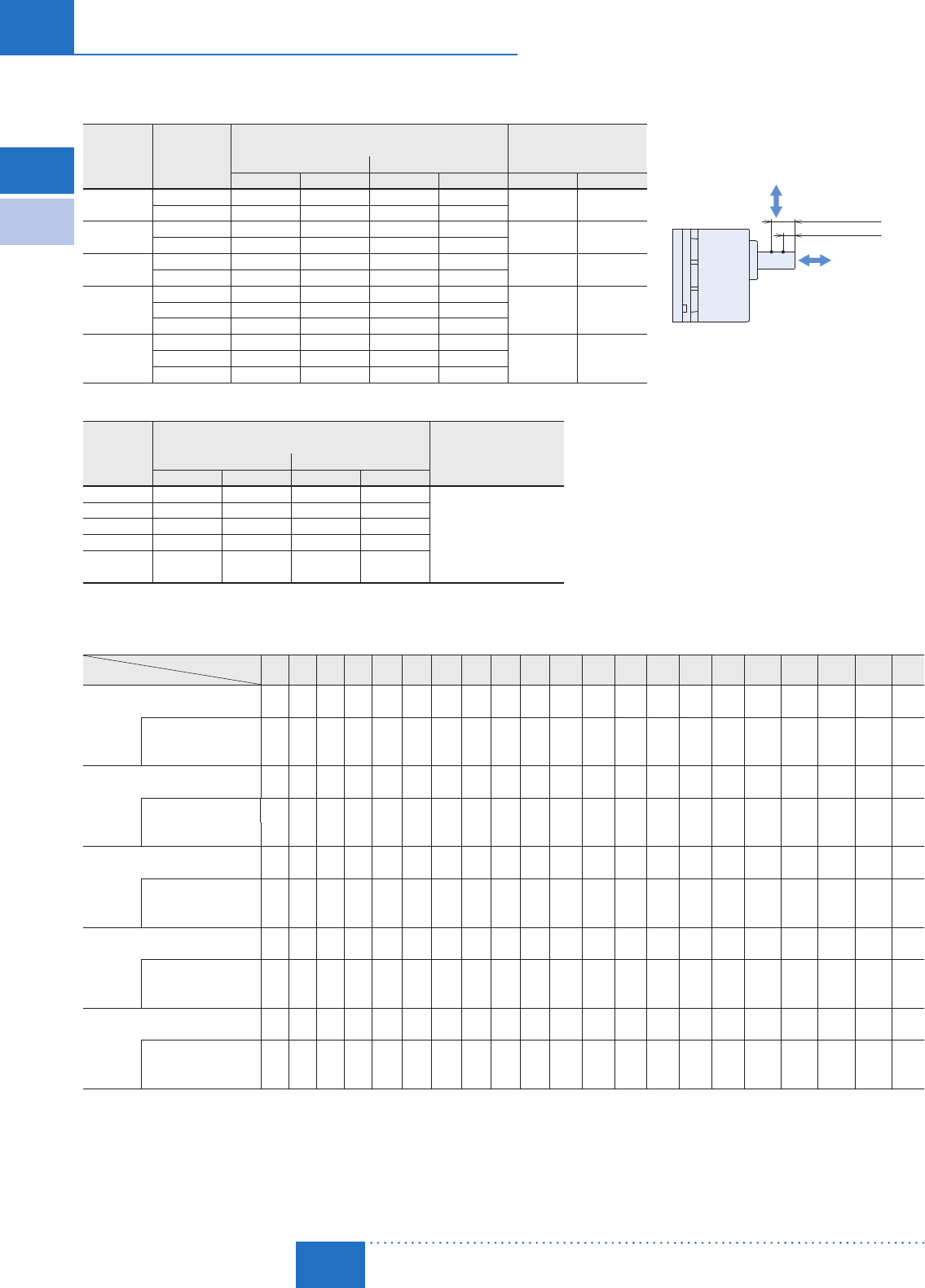
■Permissible Radial Load and Permissible Axial Load
Combination Type
Product
Name Gear Ratio
Permissible Radial Load
Permissible Axial Load
10 mm (0.39 in.)
20 mm (0.79 in.)
Distance from Output Shaft End
Radial Load
Axial Load
Distance from the End of the Gearhead Output Shaft
10 mm (0.39 in.) 20 mm (0.79 in.)
N lb. N lb. N lb.
DSCI26 5∼25 150 33 200 45 40 9.0
30∼360 200 45 300 67
DSCI315 5∼25 200 45 300 67 80 18.0
30∼360 300 67 400 90
DSCI425 5∼25 300 67 350 78 100 22
30∼360 450 101 550 123
DSCI540
DSCI560
5∼9400 90 500 112
150 3312.5∼18 450 101 600 135
25∼300 500 112 700 157
DSCI590
5∼9400 90 500 112
150 3312.5∼18 450 101 600 135
25∼180 500 112 700 157
Round Shaft Type
Product
Name
Permissible Radial Load
Permissible Axial Load
Distance from the End of the Output Shaft
10 mm (0.39 in.) 20 mm (0.79 in.)
N lb. N lb.
DSCI26 50 11.2 110 24
Half of motor mass or less✽
DSCI315 40 9 60 13.5
DSCI425 90 20 140 31
DSCI540 140 31 200 45
DSCI560
DSCI590 240 54 270 60
✽Avoid applying axial loads as much as possible. If an axial load is unavoidable, keep it at half or less of the motor mass.
■Permissible Inertia J Unit: ×10-4 kg·m2 (oz-in2)
Gear Ratio
Product Name 5 6 7.5 9 12.5 15 18 25 30 36 50 60 75 90 100 120 150 180 250 300 360
DSCI26
12 18 28 40 78 110 160 260 370 540 920 1300 1700 2000 2500 3600 5000 5000 5000 5000 5000
66 98 153 220 430 600 880 1420 2000 3000 5000 7100 9300 10900 13700 19700 27000 27000 27000 27000 27000
During Instantaneous Stop
or during Bi-Directional
Operation✽
1.55 2.23 3.49 5.02 9.69 14 20.1 38.8 55.8 80.4 155 155 155 155 155 155 155 155 155 155 155
8.5 12.2 19.1 27 53 77 110 210 310 440 850 850 850 850 850 850 850 850 850 850 850
DSCI315
20 28 45 65 120 180 260 440 630 900 1500 2100 2800 3200 4000 5700 8000 8000 8000 8000 8000
109 153 250 360 660 980 1420 2400 3400 4900 8200 11500 15300 17500 22000 31000 44000 44000 44000 44000 44000
During Instantaneous Stop
or during Bi-Directional
Operation✽
3.5 5.04 7.88 11.3 21.9 31.5 45.4 87.5 126 181 350 350 350 350 350 350 350 350 350 350 350
19.1 28 43 62 120 172 250 480 690 990 1910 1910 1910 1910 1910 1910 1910 1910 1910 1910 1910
DSCI425
22 32 50 72 150 220 310 550 800 1100 2200 3200 4000 5000 6200 8900 12000 12000 12000 12000 12000
120 175 270 390 820 1200 1700 3000 4400 6000 12000 17500 22000 27000 34000 49000 66000 66000 66000 66000 66000
During Instantaneous Stop
or during Bi-Directional
Operation✽
7.75 11.2 17.4 25.1 48.4 69.8 100 194 279 402 775 775 775 775 775 775 775 775 775 775 775
42 61 95 137 260 380 550 1060 1530 2200 4200 4200 4200 4200 4200 4200 4200 4200 4200 4200 4200
DSCI540
DSCI560
45 65 100 150 300 420 620 1100 1600 2300 4500 6000 8000 10000 12000 17000 25000 25000 25000 25000 −
250 360 550 820 1640 2300 3400 6000 8800 12600 25000 33000 44000 55000 66000 93000 137000 137000 137000 137000 −
During Instantaneous Stop
or during Bi-Directional
Operation✽
27.5 39.6 61.9 89.1 172 248 356 688 990 1426 2750 2750 2750 2750 2750 2750 2750 2750 2750 2750 −
150 220 340 490 940 1360 1950 3800 5400 7800 15000 15000 15000 15000 15000 15000 15000 15000 15000 15000 −
DSCI590
45 65 100 150 300 420 620 1100 1600 2300 4500 6000 8000 10000 12000 17000 25000 25000 −−−
250 360 550 820 1640 2300 3400 6000 8800 12600 25000 33000 44000 55000 66000 93000 137000 137000 − − −
During Instantaneous Stop
or during Bi-Directional
Operation✽
27.5 39.6 61.9 89.1 172 248 356 688 990 1426 2750 2750 2750 2750 2750 2750 2750 2750 −−−
150 220 340 490 940 1360 1950 3800 5400 7800 15000 15000 15000 15000 15000 15000 15000 15000 − − −
✽The values are when deceleration control is ON
Electromagnetic
Brake Type
Parallel Shaft

D-149
Brushless Motors/AC Speed Control Motors
D-149
Brushless
Motors
Overview,
Product
Series
AC Input
BMU
AC Input
BLE
AC Input
BLF
AC Input
BX
DC Input
BLH
DSC
BHF
AC Speed
Control
Motors
Accessories
Installation
CAD Data
Manuals www.orientalmotor.com Technical
Support TEL: (800) 468-3982
E-mail: techsupport@orientalmotor.com
■How to Read Speed – Torque Characteristics
The characteristics on the right shows the relationship between each setting
speed and torque when a speed control motor is operated.
① 50 Hz Safe-Operation Line ② 60 Hz Safe-Operation Line
The safe-operation line is the permissible line of torque that is limited by the
motor's permissible temperature.
Motors can be operated at the continuous rating within the safe-operation line.
The safe-operation line is determined under the most severe condition where
there is no heat conduction. Therefore, depending on the installation conditions
of the motor, it can be operated beyond the safe-operation line.
Note
When operating beyond the safe-operation line, ensure that the motor case temperature is maintained at 90˚C (194°F)
or less.
③ Starting Torque
This refers to the degree of torque with which the motor can start.
④ Permissible Torque on Combination Types
This refers to the permissible value of the motor torque when operating with the
gearhead installed.
Because the permissible torque of the combination type varies according to the
gear ratio, use the motor without exceeding the value on the list of permissible
torques.
14001000
500
01600
0.1
0.2
0.3
0.4
0.5 ①②
50 Hz
60 Hz
③
90
④
Torque [N·m]
Speed [r/min]
0
Torque [oz-in]
70
60
50
40
30
20
10
■Speed – Torque Characteristics (Reference values)
② 60 Hz Safe-Operation Line
① 50 Hz Safe-Operation Line ③ Starting Torque ④ Permissible Torque on Combination Types
All output characteristics are representative values. (For motor only)
The permissible torque and starting torque of the motor vary according to the voltage. Use after checking the specifications and permissible
torque of the combination type.
6 W (1/125 HP) 15 W (1/50 HP)
14001000
500 1600
20
0
40
60
80
100
50 Hz
60 Hz
①②
③
90
④
Torque [mN·m]
0
Torque [oz-in]
14
12
10
8
6
4
2
Speed [r/min]
14001000500
01600
40
80
120
160
200
Speed [r/min]
50 Hz
60 Hz
①②
③
90
④
Torque [mN·m]
0
Torque [oz-in]
25
20
15
10
5
25 W (1/30 HP) 40 W (1/19 HP)
14001000500 1600
0.1
0
0.2
0.3
0.4
①②
60 Hz
50 Hz
③
90
④
Torque [N·m]
Speed [r/min]
0
Torque [oz-in]
50
40
30
20
10
14001000
500
01600
0.1
0.2
0.3
0.4
0.5 ①②
50 Hz
60 Hz
③
90
④
Torque [N·m]
Speed [r/min]
0
Torque [oz-in]
70
60
50
40
30
20
10
60 W (1/12 HP) 90 W (1/8 HP)
14001000500
01600
0.2
0.4
0.6
0.8
50 Hz
60 Hz
③
②①
90
④
Torque [N·m]
Speed [r/min]
0
Torque [oz-in]
100
80
60
40
20
140010005000 1600
①
②50 Hz
60 Hz
③
0.2
0.4
0.6
0.8
1.0
1.2
90
④
Torque [N·m]
Torque [oz-in]
150
125
100
75
50
25
Speed [r/min]
0
D-150
D-150 AC Speed Control Motors/DSC Series
ORIENTAL MOTOR GENERAL CATALOG
2015/2016 Page
Features D-138 / System Configuration D-142 / Product Line D-143 / Specifications D-145 / Characteristics D-149
Dimensions D-150 / Connection and Operation D-171 / Motor and Controller Combinations D-156
Standard Type
Parallel Shaft/
Round Shaft
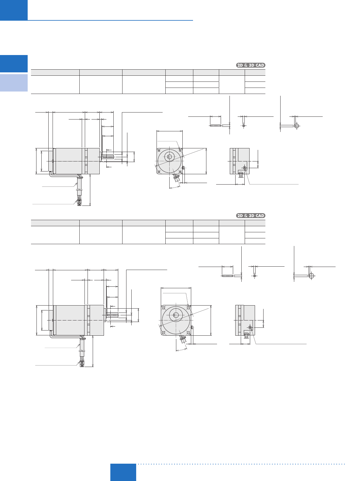
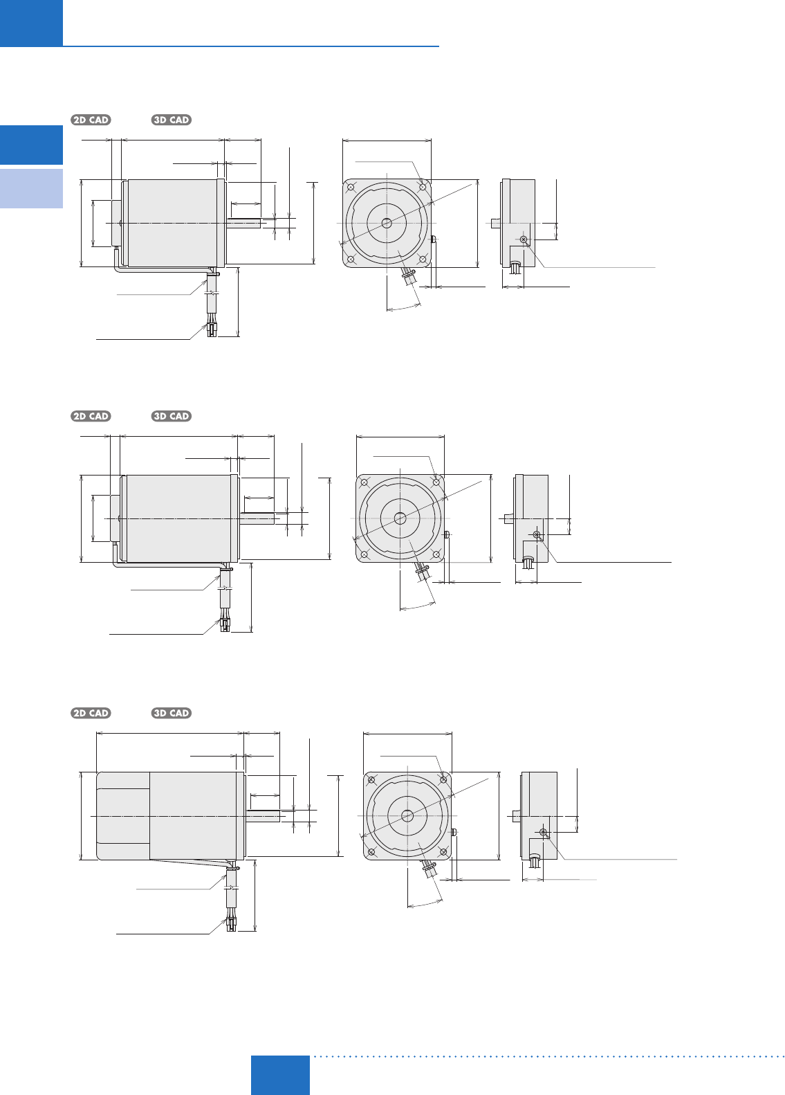
Combination Type
6 W (1/125 HP)
Product Name Motor Product Name
Gearhead Product Name
Gear Ratio L Mass kg (lb.) 2D CAD
DSCI26UA-□A -3V
DSCI26EC-□A -3V
2IK6UGV-UA
2IK6UGV-EC 2GV□A
5∼25 34 (1.34) 1.3
(2.9)
A1401A
30∼120 38 (1.50) A1401B
150∼360 43 (1.69) A1401C
60 (2.36)
500 (20)
5 max.
(0.20 max.)
22.5°
10
(0.39)
L
7
(0.28)
75 (2.95)
4
32±1
(1.26±0.04)
A
A
ϕ60 (ϕ2.36)
ϕ47
(ϕ1.85)
25±0.2
(0.984±0.008)
25
(0.98)
60
(2.36)
21.5 (0.85)
15.5
(0.61)
[
ϕ0.3750−0.0005 (3/8”)
]
0
0.0000
ϕ9.525−0.013
10±0.5
(0.39±0.02)
ϕ23−0.021
0
0.0000
(
ϕ0.9055−0.0008
)
2.383 0
(
0.0938 0.0000
)
+0.040
+0.0016
2.383−0.025
(
0.0938−0.0010
)
0
0.0000
2.383−0.025
(
0.0938−0.0010
)
0
0.0000
1.321
(
0.052
)
+0.381
+0.015
0.000
0
26.5
(1.04)
ϕ70±0.5
(ϕ2.76±0.02)
(0.16)
Protective Earth Terminal M4
5557-06R-210 (MOLEX)
4×ϕ4.5 Thru
(ϕ0.177)
Detail Drawing of Protective Earth Terminal
Parallel Key (Included) A-A
Tube ϕ9.5 (ϕ0.37)
15 W (1/50 HP)
Product Name Motor Product Name
Gearhead Product Name
Gear Ratio L Mass kg (lb.) 2D CAD
DSCI315UA-□A -3V
DSCI315EC-□A -3V
3IK15UGV-UA
3IK15UGV-EC 3GV□A
5∼25 38 (1.50) 1.8
(4.0)
A1402A
30∼120 43 (1.69) A1402B
150∼360 48 (1.89) A1402C
L80 (3.15)
A
A
22.5°
5557-06R-210 (MOLEX)
10
(0.39)
7
(0.28)
32±1
(1.26±0.04)
25
(0.98)
ϕ12.7−0.013
0.0000
0
[
ϕ0.5000−0.0005 (1/2”)
]
12±0.5
(0.47±0.02)
ϕ31−0.025
0
0.0000
(
ϕ1.2205−0.0010
)
70 (2.76)
500 (20)
70
(2.76)
ϕ82
±0.5
(ϕ3.23
±0.02
)
5 max.
(0.20 max.)
21.5
(0.85)
16.5
(0.65)
3.175−0.025
3.175−0.025
0
25±0.2
(0.984±0.008)
(
0.070 0.000
)
+0.381
+0.015
3.175 0
+0.040
+0.0016
0.0000
(
0.1250−0.0010
)
(
0.1250−0.0010
)
0.0000
01.778 0
(
0.1250 0.0000
)
ϕ69 (ϕ2.72)
ϕ47
(ϕ1.85)
4.5
(0.18)
26.5
(1.04)
Tube ϕ9.5 (ϕ0.37)
4×ϕ6.5
(ϕ0.256) Thru
Detail Drawing of Protective Earth Terminal
Protective Earth Terminal M4
Parallel Key (Included)A-A
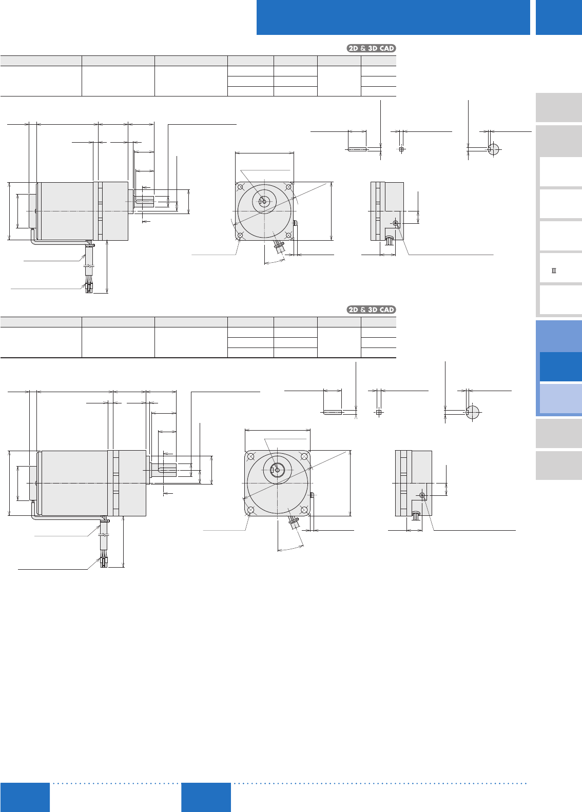
■Dimensions Unit = mm (in.)
"Installation screws" are included with the combination type. Dimensions of installation screws ➜ Page C-215
A number indicating the gear ratio is entered where the box □ is located within the product name.
Electromagnetic
Brake Type
Parallel Shaft
D-151
Brushless Motors/AC Speed Control Motors
D-151
Brushless
Motors
Overview,
Product
Series
AC Input
BMU
AC Input
BLE
AC Input
BLF
AC Input
BX
DC Input
BLH
DSC
BHF
AC Speed
Control
Motors
Accessories
Installation
CAD Data
Manuals www.orientalmotor.com Technical
Support TEL: (800) 468-3982
E-mail: techsupport@orientalmotor.com
25 W (1/30 HP)
Product Name Motor Product Name
Gearhead Product Name
Gear Ratio L Mass kg (lb.) 2D CAD
DSCI425UA-□A -3V
DSCI425EC-□A -3V
4IK25UGV-UA
4IK25UGV-EC 4GV□A
5∼25 41 (1.61) 2.55
(5.6)
A1403A
30∼120 46 (1.81) A1403B
150∼360 51 (2.01) A1403C
L
A
A
22.5°
5557-06R-210 (MOLEX)
ϕ47
(ϕ1.85)
ϕ79 (ϕ3.11)
85 (3.35)
25
(0.98)
ϕ15.875−0.013
0
ϕ33−0.025
0
0.0000
(
ϕ1.2992−0.0010
)
0.0000
[
ϕ0.6250−0.0005 (5/8”)
]
7
(0.28)
6.5
(0.26)
35±1
(1.38±0.04)
10
(0.39)
13±0.5
(0.51±0.02)
80 (3.15)
500 (20)
ϕ94
±0.5
(ϕ3.70
±0.02
)
80
(3.15)
5 max.
(0.20 max.)
21.5
(0.85)
16.5
(0.65)
2.743 0
+0.381
4.763 0
+0.040
+0.0016
+0.015
(
0.1875 0.0000
)
(
0.108 0.000
)
4.763−0.025
(
0.1875−0.0010
)
0.0000
0
25±0.2
(0.984±0.008)
4.763−0.025
0
0.0000
(
0.1875−0.0010
)
27
(1.06)
No.10-24 UNC
10 (0.39) Deep
4×ϕ6.5
(ϕ0.256) Thru
Tube ϕ9.5 (ϕ0.37)Protective Earth Terminal M4
Detail Drawing of Protective Earth Terminal
Parallel key (Included) A-A
40 W (1/19 HP)
Product Name Motor Product Name
Gearhead Product Name
Gear Ratio L Mass kg (lb.) 2D CAD
DSCI540UA-□A -3V
DSCI540EC-□A -3V
5IK40UGV-UA
5IK40UGV-EC 5GV□A
5∼18 45 (1.77) 4.1
(9.0)
A1404A
25∼100 58 (2.28) A1404B
120∼300 64 (2.52) A1404C
L
A
A
22.5°
5557-06R-210 (MOLEX)
ϕ47
(ϕ1.85)
ϕ89 (ϕ3.50)
10
(0.39)7.5
(0.30)
105 (4.13)
(
ϕ1.5354−0.0010
)
42±1
(1.65±0.04)
34
(1.34)
5
(0.20)
25
(0.98)
18±0.5
(0.71±0.02)
ϕ19.050−0.013
[
ϕ0.7500−0.0005 (3/4”)
]
0
ϕ39−0.025
0
0.0000
0.0000
ϕ104
±0.5
(ϕ4.09
±0.02
)
90 (3.54)
5 max.
(0.20 max.)
90 (3.54)
500 (20)
21.5
(0.85)
16.5
(0.65)
2.692 0
(
0.106 0.000
)
+0.381
+0.015
4.763 0
(
0.1875 0.0000
)
+0.040
+0.0016
0.0000
25±0.2
(0.984±0.008)
0
4.763−0.025
(
0.1875−0.0010
)
4.763−0.025
(
0.1875−0.0010
)
0
0.0000
Tube ϕ9.5 (ϕ0.37)4×ϕ8.5
(ϕ0.335) Thru
No.12-24 UNC
12 (0.47) Deep
Protective Earth Terminal M4
Detail Drawing of Protective Earth Terminal
A-AParallel Key (Included)
D-152
D-152 AC Speed Control Motors/DSC Series
ORIENTAL MOTOR GENERAL CATALOG
2015/2016 Page
Features D-138 / System Configuration D-142 / Product Line D-143 / Specifications D-145 / Characteristics D-149
Dimensions D-150 / Connection and Operation D-171 / Motor and Controller Combinations D-156
Standard Type
Parallel Shaft/
Round Shaft
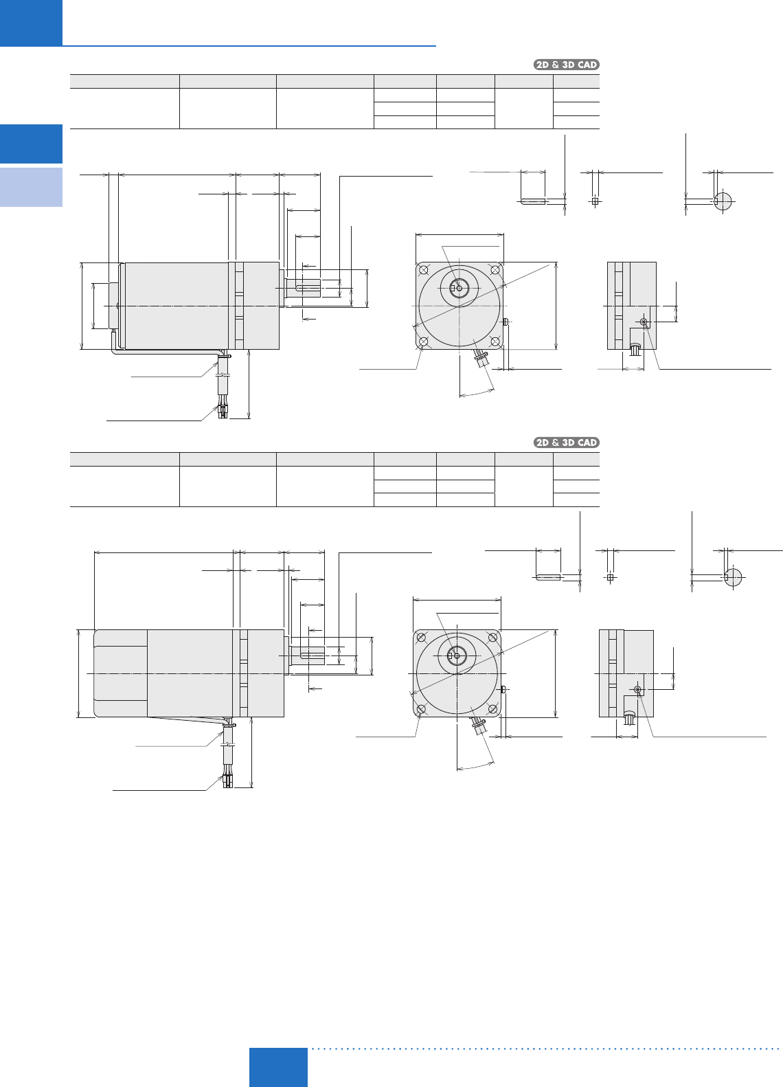
60 W (1/12 HP)
Product Name Motor Product Name
Gearhead Product Name
Gear Ratio L Mass kg (lb.) 2D CAD
DSCI560UA-□
A -3V
DSCI560EC-□
A -3V
5IK60UGVH-UA
5IK60UGVH-EC 5GVH□A
5∼18 45 (1.77) 4.6
(10.1)
A1405A
25∼100 58 (2.28) A1405B
120∼300 64 (2.52) A1405C
L
A
A
22.5°
5557-06R-210 (MOLEX)
120 (4.72)
25
(0.98)
ϕ19.050−0.013
0.0000
0
[
ϕ0.7500−0.0005 (3/4”)
]
7.5
(0.30)
5
(0.20)
42
±1
(1.65
±0.04
)
34
(1.34)
ϕ39
−0.025
0
0.0000
(
ϕ1.5354−0.0010
)
18
±0.5
(0.71
±0.02
)
10
(0.39)
ϕ47
(ϕ1.85)
ϕ89 (ϕ3.50)
90 (3.54)
500 (20)
ϕ104
±0.5
(ϕ4.09
±0.02
)
90
(3.54)
5
max.
(0.20 max.)
21.5
(0.85)
16.5
(0.65)4.763 0
(
0.1875 0.0000
)
+0.040
+0.0016
2.692 0
(
0.106 0.000
)
+0.381
+0.015
25±0.2
(0.984±0.008)
0
4.763−0.025
(
0.1875−0.0010
)
0.0000
4.763−0.025
(
0.1875−0.0010
)
0
0.0000
Tube ϕ9.5 (ϕ0.37)4×ϕ8.5
(ϕ0.335) Thru
No.12-24 UNC
12 (0.47) Deep
Protective Earth Terminal M4
Detail Drawing of Protective Earth Terminal
Parallel Key (Included)A-A
90 W (1/8 HP)
Product Name Motor Product Name
Gearhead Product Name
Gear Ratio L Mass kg (lb.) 2D CAD
DSCI590UA-□A -3V
DSCI590EC-□A -3V
5IK90UGVR-UA
5IK90UGVR-EC 5GVR□A
5∼15 45 (1.77) 4.8
(10.6)
A1406A
18∼36 58 (2.28) A1406B
50∼180 70 (2.76) A1406C
150 (5.91)L
A
A
22.5°
90 (3.54)
500 (20)
90
(3.54)
No.12-24 UNC
12 (0.47) Deep
4×ϕ8.5
(ϕ0.335) Thru
ϕ104
±0.5
(ϕ4.09
±0.02
)
5 max.
(0.20 max.)
21.5
(0.85)
16.5
(0.65)
25±0.2
(0.984±0.008)
0
4.763−0.025
0.0000
(
0.1875−0.0010
)
4.763−0.025
0
0.0000
(
0.1875−0.0010
)
4.763 0
+0.040
+0.0016
(
0.1875 0.0000
)
2.692 0
+0.381
+0.015
(
0.106 0.000
)
7.5
(0.30)
□90 (□3.54)
5
(0.20)
42
±1
(1.65
±0.04
)
34
(1.34)
25
(0.98)
5557-06R-210 (MOLEX)
ϕ19.050
−0.013
0.0000
0
[
ϕ0.7500−0.0005 (3/4”)
]
ϕ39
−0.025
0
0.0000
(
ϕ1.5354−0.0010
)
Tube ϕ9.5 (ϕ0.37)
18
±0.5
(0.71
±0.02
)
Protective Earth Terminal M4
Detail Drawing of Protective Earth Terminal
A-AParallel Key (Included)
Electromagnetic
Brake Type
Parallel Shaft
D-153
Brushless Motors/AC Speed Control Motors
D-153
Brushless
Motors
Overview,
Product
Series
AC Input
BMU
AC Input
BLE
AC Input
BLF
AC Input
BX
DC Input
BLH
DSC
BHF
AC Speed
Control
Motors
Accessories
Installation
CAD Data
Manuals www.orientalmotor.com Technical
Support TEL: (800) 468-3982
E-mail: techsupport@orientalmotor.com
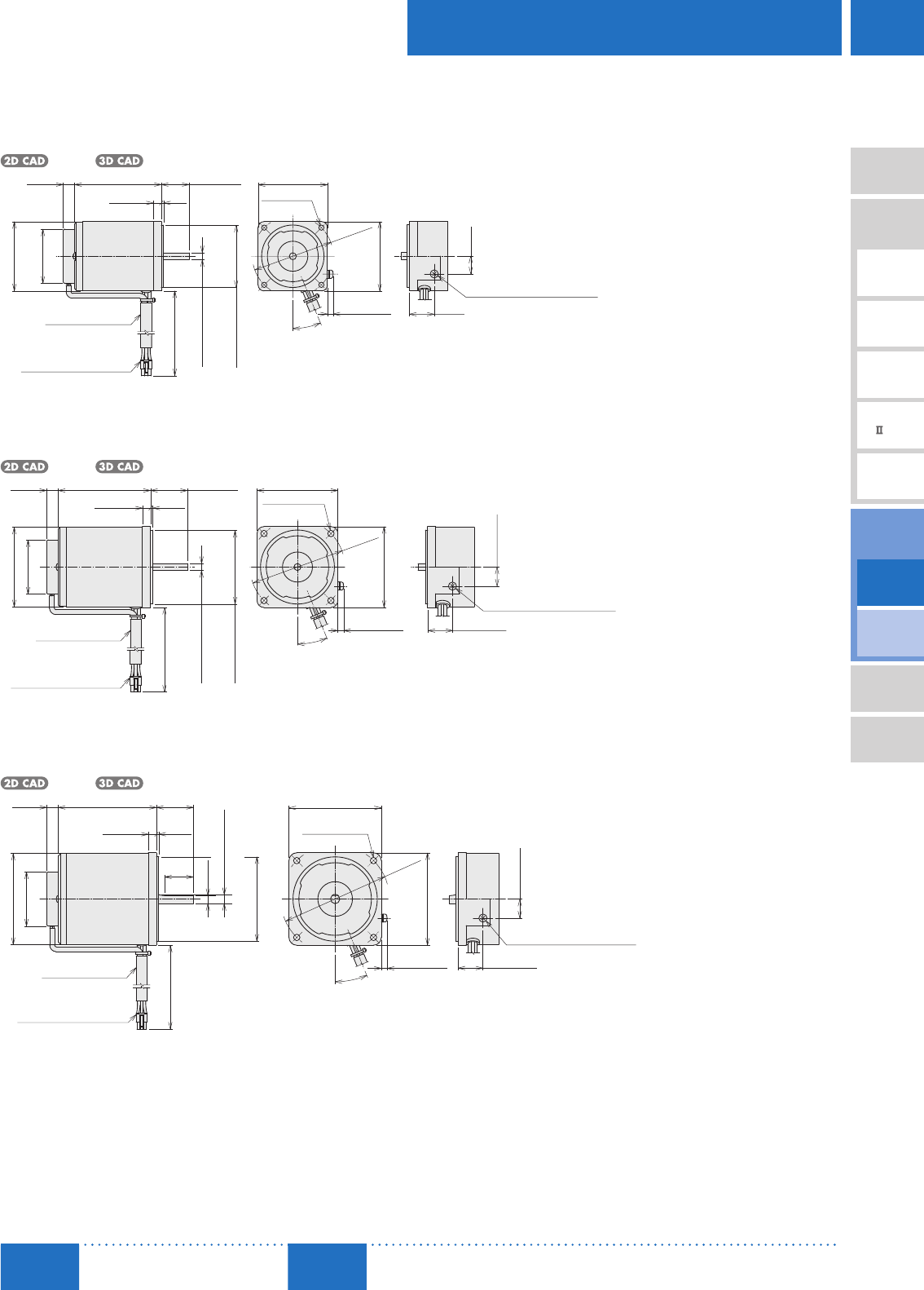
Round Shaft Type
6 W (1/125 HP)
DSCI26UA-A-3V, DSCI26EC-A-3V
Motor: 2IK6UA-UA, 2IK6UA-EC
Mass: 0.8 kg (1.76 lb.)
A1256
60 (2.36)
60
(2.36)
ϕ70±0.5
(ϕ2.76±0.02)
5 max.
(0.20 max.)
22.5°
21.5
(0.85)
15.5
(0.61)
10
(0.39)7 (0.28)
75 (2.95)
ϕ60
(ϕ2.36)
ϕ47
(ϕ1.85)
500 (20)
24±1
(0.94±0.04)
2
(0.08)
0
0.0000
0.0000
ϕ54−0.030
(
ϕ2.1260−0.0012
)
0
ϕ6−0.012
(
ϕ0.2362−0.0005
)
Protective Earth Terminal M4
5557-06R-210 (MOLEX)
Tube ϕ9.5 (ϕ0.37)
4×ϕ4.5
(ϕ0.177)Thru
Detail Drawing of Protective Earth Terminal
15 W (1/50 HP)
DSCI315UA-A-3V, DSCI315EC-A-3V
Motor: 3IK15UA-UA, 3IK15UA-EC
Mass: 1.2 kg (2.6 lb.)
A1257
2
(0.08)
32±1
(1.26±0.04)
7 (0.28)
80 (3.15)10
(0.39)
ϕ47
(ϕ1.85)
ϕ69 (ϕ2.72)
500 (20)
70
(2.76)
ϕ82±0.5
(ϕ3.23
±0.02
)
22.5°
5 max.
(0.20 max.)
70 (2.76)
16.5 (0.65)
21.5 (0.85)
5557-06R-210 (MOLEX)
0
0.0000
ϕ64−0.030
(
ϕ2.5197−0.0012
)
0
ϕ6−0.012
(
ϕ0.2362−0.0005
)
0.0000
4×ϕ5.5
(ϕ0.217) Thru
Tube ϕ9.5 (ϕ0.37)
Protective Earth Terminal M4
Detail Drawing of Protective Earth Terminal
25 W (1/30 HP)
DSCI425UA-A-3V, DSCI425EC-A-3V
Motor: 4IK25UA-UA, 4IK25UA-EC
Mass: 1.6 kg (3.5 lb.)
A1258
32±1
(1.26±0.04)
7 (0.28)
85 (3.35)10
(0.39)
ϕ47
(ϕ1.85)
ϕ79 (ϕ3.11)
80 (3.15)
80
(3.15)
ϕ94
±0.5
(ϕ3.70
±0.02
)
22.5°
5 max.
(0.20 max.)
5557-06R-210 (MOLEX)
500 (20)
16.5 (0.65)
21.5 (0.85)
25
(0.98)
2
(0.08)
7 (0.28)
0
0.0000
0.0000
(
ϕ0.3150−0.0006
)
0
ϕ73−0.030
(
ϕ2.8740−0.0012
)
ϕ8−0.015
4×ϕ5.5
(ϕ0.217) Thru
Tube ϕ9.5 (ϕ0.37)
Protective Earth Terminal M4
Detail Drawing of Protective Earth Terminal
D-154
D-154 AC Speed Control Motors/DSC Series
ORIENTAL MOTOR GENERAL CATALOG
2015/2016 Page
Features D-138 / System Configuration D-142 / Product Line D-143 / Specifications D-145 / Characteristics D-149
Dimensions D-150 / Connection and Operation D-171 / Motor and Controller Combinations D-156
Standard Type
Parallel Shaft/
Round Shaft
40 W (1/19 HP)
DSCI540UA-A-3V, DSCI540EC-A-3V
Motor: 5IK40UA-UA, 5IK40UA-EC
Mass: 2.6 kg (5.7 lb.)
A1259
500 (20)
37±1
(1.46±0.04)
7.5 (0.30)
105 (4.13)10
(0.39)
ϕ47
(ϕ1.85)
ϕ89 (ϕ3.50)
16.5 (0.65)
21.5 (0.85)
90 (3.54)
ϕ104
±0.5
(ϕ4.09
±0.02
)
5 max.
(0.20 max.)
90 (3.54)
22.5°
5557-06R-210 (MOLEX)
2
(0.08)
0
ϕ10−0.015
(
ϕ0.3937−0.0006
)
9 (0.35)
0
0.0000
0.0000
ϕ83−0.035
(
ϕ3.2677−0.0014
)
30
(1.18)
Tube ϕ9.5 (ϕ0.37)
Protective Earth Terminal M4
4×ϕ6.5
(ϕ0.256) Thru
Detail Drawing of Protective Earth Terminal
60 W (1/12 HP)
DSCI560UA-A-3V, DSCI560EC-A-3V
Motor: 5IK60UA-UA, 5IK60UA-EC
Mass: 3.1 kg (6.8 lb.)
A1260
500 (20)
2
(0.08)
371
7.5 (0.30)
120 (4.72)10
(0.39)
47
(1.85)
89 (3.50)
16.5 (0.65)
21.5 (0.85)
90 (3.54)
104
0.5
(4.09
0.02
)
5 max.
(0.20 max.)
90 (3.54)
22.5°
5557-06R-210 (MOLEX)
30
(1.18)
0
0.0000
0.0000
120.018
(
0.47240.0007
)
0
830.035
(
3.26770.0014
)
11 (0.43)
(1.460.04)
Tube 9.5 (0.37)
Protective Earth Terminal M4
4×6.5
(0.256) Thru
Detail Drawing of Protective Earth Terminal
90 W (1/8 HP)
DSCI590UA-A-3V, DSCI590EC-A-3V
Motor: 5IK90UA-UA, 5IK90UA-EC
Mass: 3.3 kg (7.3 lb.)
A1261
5557-06R-210 (MOLEX)
500 (20)
7.5 (0.30)
150 (5.91)
□90 (□3.54)
2
(0.08)
37±1
16.5 (0.65)
21.5 (0.85)
90 (3.54)
ϕ104
±0.5
(ϕ4.09
±0.02
)
5 max.
(0.20 max.)
90 (3.54)
30
(1.18)
0
0.0000
(
ϕ0.4724−0.0007
)
11 (0.43)
0
(
ϕ3.2677−0.0014
)
0.0000
ϕ12−0.018
ϕ83−0.035
(1.46±0.04)
22.5°
Tube ϕ9.5 (ϕ0.37)
Protective Earth Terminal M4
4×ϕ6.5
(ϕ0.256) Thru
Detail Drawing of Protective Earth Terminal
Electromagnetic
Brake Type
Parallel Shaft
D-155
Brushless Motors/AC Speed Control Motors
D-155
Brushless
Motors
Overview,
Product
Series
AC Input
BMU
AC Input
BLE
AC Input
BLF
AC Input
BX
DC Input
BLH
DSC
BHF
AC Speed
Control
Motors
Accessories
Installation
CAD Data
Manuals www.orientalmotor.com Technical
Support TEL: (800) 468-3982
E-mail: techsupport@orientalmotor.com
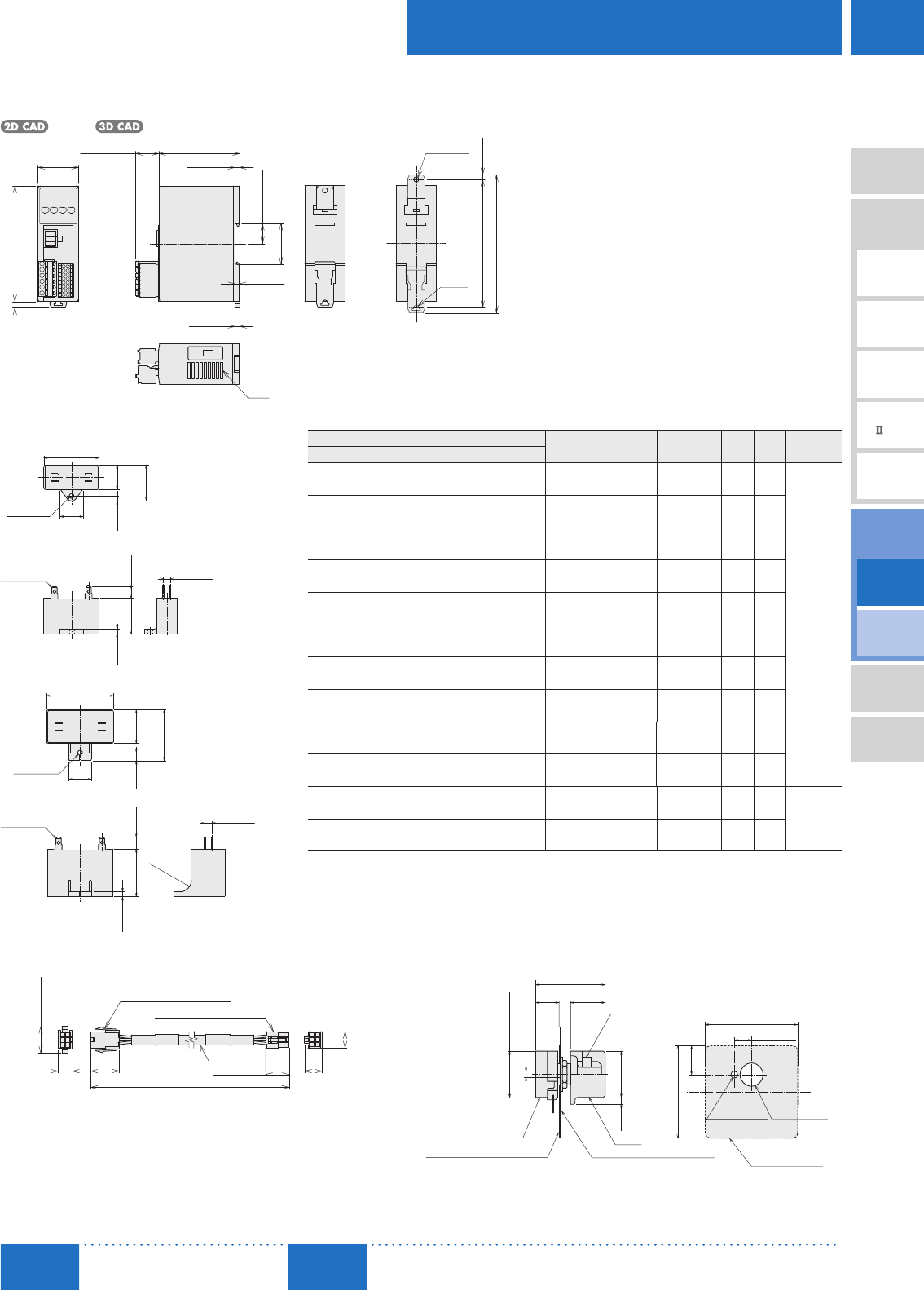
Speed Controller
DSC-U
Mass: 0.2 kg (0.44 lb.)
A1262
4 (0.16)
4 (0.16)
(5.5) (0.22)100 (3.94)
35
(1.38)
70 (2.76)
4 (0.16)
20 max.
(0.79 max.)
17.5 (0.69)
35.1
(1.38)
R2.25
(R0.09)
ϕ4.5
(ϕ0.177) Thru
111±0.5 (4.37±0.02)
120.5 max. (4.74 max.)
(4.5)
(0.18)
Slits
DIN Installation Screw Installation
Capacitor (Included)
Dimensions No. ①
4.3
(0.169)
20
(0.79)
A
C
B+10 (0.39)
B
4.5
(0.18)
4
(0.16)10
(0.39)
6 (0.24)
AMP#187
Dimensions No. ②
6 (0.24)
A
CB7
(0.28)
20
(0.79)
10
(0.39)
AMP#187
4.3
(0.169)
4
(0.16)
B+15 (0.59)
R10
(R0.39)
Capacitor Dimensions Unit: mm (in.)
Product Name Capacitor
Product Name ABC
Mass
g (oz.)
Dimensions
No.
Combination Type Round Shaft Type
DSCI26UA-□A -3V DSCI26UA-A -3V CH25FAUL2 31 17 27 21
①
(1.22) (0.67) (1.06) (0.74)
DSCI26EC-□A -3V DSCI26EC-A -3V CH06BFAUL 31 14.5 23.5 18
(1.22) (0.57) (0.93) (0.64)
DSCI315UA-□A -3V DSCI315UA-A -3V CH45FAUL2 37 18 27 26
(1.46) (0.71) (1.06) (0.92)
DSCI315EC-□A -3V DSCI315EC-A -3V CH10BFAUL 37 18 27 27
(1.46) (0.71) (1.06) (0.95)
DSCI425UA-□A -3V DSCI425UA-A -3V CH65CFAUL2 48 19 29 35
(1.89) (0.75) (1.14) (1.24)
DSCI425EC-□A -3V DSCI425EC-A -3V CH15BFAUL 38 21 31 37
(1.50) (0.83) (1.22) (1.31)
DSCI540UA-□A -3V DSCI540UA-A -3V CH90CFAUL2 48 22.5 31.5 45
(1.89) (0.89) (1.24) (1.59)
DSCI540EC-□A -3V DSCI540EC-A -3V CH23BFAUL 48 21 31 43
(1.89) (0.83) (1.22) (1.52)
DSCI560UA-□A -3V DSCI560UA-A -3V CH120CFAUL2 58 22 35 60
(2.28) (0.87) (1.38) (2.1)
DSCI560EC-□A -3V DSCI560EC-A -3V CH30BFAUL 58 21 31 50
(2.28) (0.83) (1.22) (1.77)
DSCI590UA-□A -3V DSCI590UA-A -3V CH200CFAUL2 58 29 41 91
②
(2.28) (1.14) (1.61) (3.2)
DSCI590EC-□A -3V DSCI590EC-A -3V CH60BFAUL 58 29 41 92
(2.28) (1.14) (1.61) (3.2)
A capacitor cap is included with the capacitor.
Connection Cable (Included)
8 (0.31)
(23) (0.91)
13.8
(0.54)
23.9 (0.94)19.6 (0.77)
5559-06P-210 (MOLEX)
5557-06R-210 (MOLEX)
(12) (0.47)(15) (0.59)
3000 (9.8 ft.)
Motor Side Speed Controller Side
External Speed Potentiometer (Included)
9.5
(0.37)
ϕ2.8 (ϕ0.11)
15
(0.59)
3
(0.12)
Knob
Dial Plate
□40 (□1.57) t=0.5 (0.02)
Insulated Sheet
□40 (□1.57) t=0.5 (0.02)
Potentiometer
40 (1.57)
7.5 (0.30)
12.5
(0.49)
40 (1.57)
Insulated Sheet
ϕ30.2
(ϕ
0.1180.008
)
ϕ9.50.2
(
ϕ0.3740.008
)
30 (1.18) min.
ϕ20 (ϕ0.79)
ϕ20
(ϕ0.79)
M4×6 (0.24) Deep
(Screw)
Recommended thickness of a mounting plate is a maximum of 4.5 mm (0.18 in.).

D-156
D-156 AC Speed Control Motors/DSC Series
ORIENTAL MOTOR GENERAL CATALOG
2015/2016 Page
Features D-138 / System Configuration D-142 / Product Line D-143 / Specifications D-145 / Characteristics D-149
Dimensions D-150 / Connection and Operation D-171 / Motor and Controller Combinations D-156
Standard Type
Parallel Shaft/
Round Shaft
Electromagnetic
Brake Type
Parallel Shaft
■List of Motor and Speed Controller Combinations
Parallel Shaft Combination Type
Output Power Product Name Combination Type Motor Product Name✽Motor Product Name Gearhead Product Name Speed Controller Product Name
6 W
(1/125 HP)
DSCI26UA- □ A-3V 2IK6UUA- □ A 2IK6UGV-UA 2GV □ A
DSC-U
DSCI26EC- □ A-3V 2IK6UEC- □ A 2IK6UGV-EC
15 W
(1/50 HP)
DSCI315UA- □ A-3V 3IK15UUA- □ A 3IK15UGV-UA 3GV □ A
DSCI315EC- □ A-3V 3IK15UEC- □ A 3IK15UGV-EC
25 W
(1/30 HP)
DSCI425UA- □ A-3V 4IK25UUA- □ A 4IK25UGV-UA 4GV □ A
DSCI425EC- □ A-3V 4IK25UEC- □ A 4IK25UGV-EC
40 W
(1/19 HP)
DSCI540UA- □ A-3V 5IK40UUA- □ A 5IK40UGV-UA 5GV □ A
DSCI540EC- □ A-3V 5IK40UEC- □ A 5IK40UGV-EC
60 W
(1/12 HP)
DSCI560UA- □ A-3V 5IK60UUA- □ A 5IK60UGVH-UA 5GVH □ A
DSCI560EC- □ A-3V 5IK60UEC- □ A 5IK60UGVH-EC
90 W
(1/8 HP)
DSCI590UA- □ A-3V 5IK90UUA- □ A 5IK90UGVR-UA 5GVR □ A
DSCI590EC- □ A-3V 5IK90UEC- □ A5IK90UGVR-EC
✽Combination type motor product names are names of special order products in which motors and gearheads are pre-assembled.
Round Shaft Type
Output Power Product Name Motor Product Name Speed Controller Product Name
6 W
(1/125 HP)
DSCI26UA-A-3V 2IK6UA-UA
DSC-U
DSCI26EC-A-3V 2IK6UA-EC
15 W
(1/50 HP)
DSCI315UA-A-3V 3IK15UA-UA
DSCI315EC-A-3V 3IK15UA-EC
25 W
(1/30 HP)
DSCI425UA-A-3V 4IK25UA-UA
DSCI425EC-A-3V 4IK25UA-EC
40 W
(1/19 HP)
DSCI540UA-A-3V 5IK40UA-UA
DSCI540EC-A-3V 5IK40UA-EC
60 W
(1/12 HP)
DSCI560UA-A-3V 5IK60UA-UA
DSCI560EC-A-3V 5IK60UA-EC
90 W
(1/8 HP)
DSCI590UA-A-3V 5IK90UA-UA
DSCI590EC-A-3V 5IK90UA-EC
A number indicating the gear ratio is entered where the box □ is located within the product name.
D-157
Brushless Motors/AC Speed Control Motors
D-157
Brushless
Motors
Overview,
Product
Series
AC Input
BMU
AC Input
BLE
AC Input
BLF
AC Input
BX
DC Input
BLH
DSC
BHF
AC Speed
Control
Motors
Accessories
Installation
CAD Data
Manuals www.orientalmotor.com Technical
Support TEL: (800) 468-3982
E-mail: techsupport@orientalmotor.com
Electromagnetic Brake Type
Parallel Shaft Combination Type
■Product Line
Combination
Type
Delivered with the motor and gearhead pre-assembled.
The combination of motor and gearhead can be changed or purchased separately. In addition, the gearhead can be
removed and the assembly position can be changed in 90° increments.
Parallel Shaft Combination Type
Output Power Power Supply Voltage Product Name Gear Ratio List Price
6 W
(1/125 HP)
Single-Phase
110/115 VAC DSCI26UAM-□A-3V
7.5, 9, 12.5, 15, 18 $379.00
25, 30, 36 $385.00
50, 60, 75, 90, 100, 120, 150, 180 $392.00
250, 300, 360 $438.00
Single-Phase
220/230 VAC DSCI26ECM-□A-3V
7.5, 9, 12.5, 15, 18 $381.00
25, 30, 36 $387.00
50, 60, 75, 90, 100, 120, 150, 180 $394.00
250, 300, 360 $440.00
15 W
(1/50 HP)
Single-Phase
110/115 VAC DSCI315UAM-□A-3V
7.5, 9, 12.5, 15, 18 $390.00
25, 30, 36 $396.00
50, 60, 75, 90, 100, 120, 150, 180 $403.00
250, 300, 360 $447.00
Single-Phase
220/230 VAC DSCI315ECM-□A-3V
7.5, 9, 12.5, 15, 18 $392.00
25, 30, 36 $398.00
50, 60, 75, 90, 100, 120, 150, 180 $405.00
250, 300, 360 $449.00
25 W
(1/30 HP)
Single-Phase
110/115 VAC DSCI425UAM-□A-3V
7.5, 9, 12.5, 15, 18 $424.00
25, 30, 36 $430.00
50, 60, 75, 90, 100, 120, 150, 180 $437.00
250, 300, 360 $484.00
Single-Phase
220/230 VAC DSCI425ECM-□A-3V
7.5, 9, 12.5, 15, 18 $427.00
25, 30, 36 $433.00
50, 60, 75, 90, 100, 120, 150, 180 $440.00
250, 300, 360 $487.00
40 W
(1/19 HP)
Single-Phase
110/115 VAC DSCI540UAM-□A-3V
7.5, 9, 12.5, 15, 18 $466.00
25, 30, 36 $473.00
50, 60, 75, 90, 100, 120, 150, 180 $480.00
250, 300 $558.00
Single-Phase
220/230 VAC DSCI540ECM-□A-3V
7.5, 9, 12.5, 15, 18 $470.00
25, 30, 36 $477.00
50, 60, 75, 90, 100, 120, 150, 180 $484.00
250, 300 $562.00
60 W
(1/12 HP)
Single-Phase
110/115 VAC DSCI560UAM-□A-3V
7.5, 9, 12.5, 15, 18 $540.00
25, 30, 36, 50, 60, 75, 90, 100 $551.00
120, 150, 180 $561.00
250, 300 $595.00
Single-Phase
220/230 VAC DSCI560ECM-□A-3V
7.5, 9, 12.5, 15, 18 $545.00
25, 30, 36, 50, 60, 75, 90, 100 $556.00
120, 150, 180 $566.00
250, 300 $600.00
90 W
(1/8 HP)
Single-Phase
110/115 VAC DSCI590UAM-□A-3V
7.5, 9, 12.5, 15, 18 $560.00
25, 30, 36, 50, 60 $580.00
75, 90, 100, 120, 150, 180 $590.00
Single-Phase
220/230 VAC DSCI590ECM-□A-3V
7.5, 9, 12.5, 15, 18 $564.00
25, 30, 36, 50, 60 $584.00
75, 90, 100, 120, 150, 180 $594.00
The following items are included with each product.
Motor, Gearhead, Speed Controller, Capacitor, Capacitor Cap, Installation Screws, Parallel Key, Connection Cable, External Speed Potentiometer, Operating Manual
Parallel Shaft Combination Type
A number indicating the gear ratio is entered where the box □ is located within the product name.
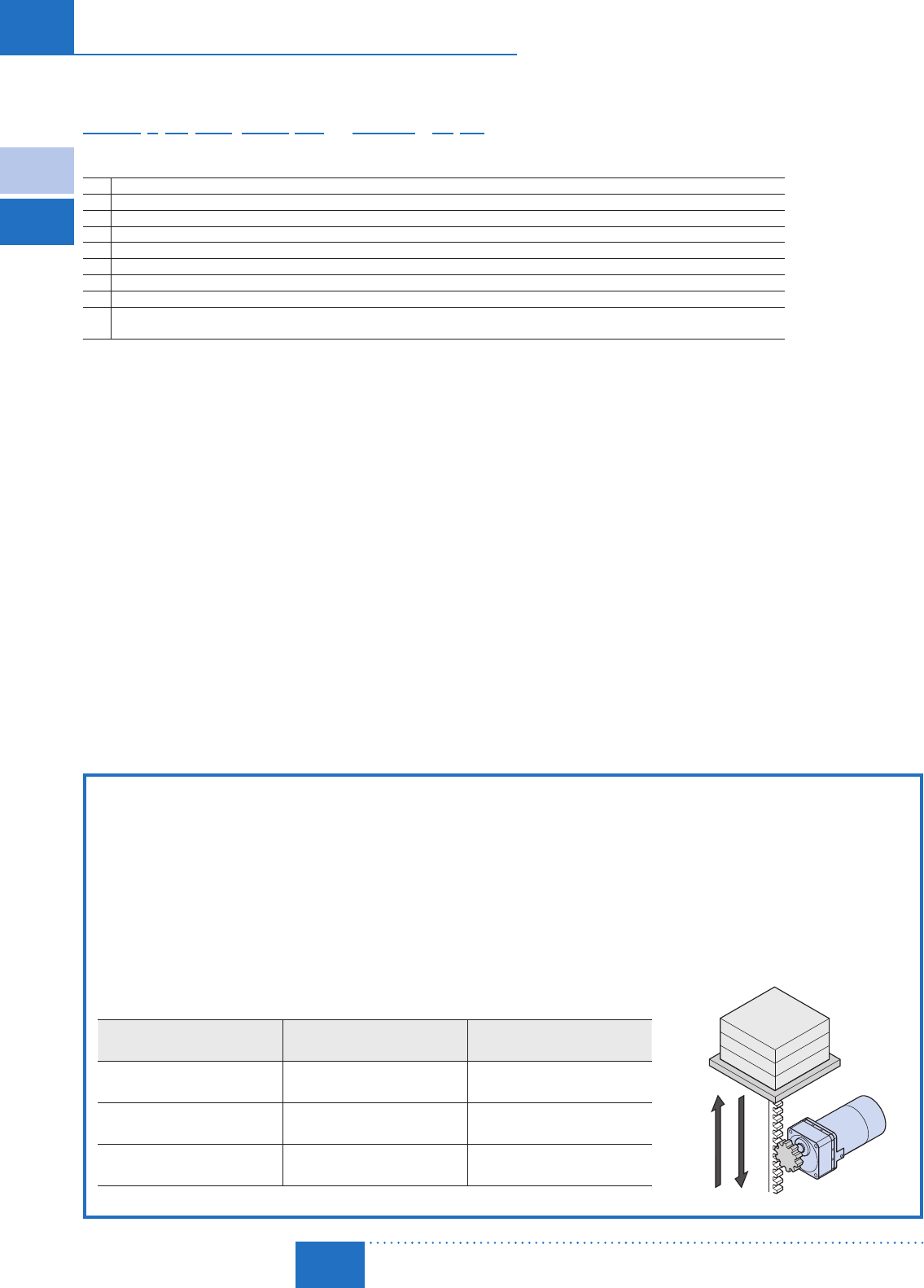
D-158
D-158 AC Speed Control Motors/DSC Series
ORIENTAL MOTOR GENERAL CATALOG
2015/2016 Page
Electromagnetic
Brake Type
Parallel Shaft
Features D-138 / System Configuration D-143 / Product Line D-157 / Specifications D-159 / Characteristics D-165
Dimensions D-166 / Connection and Operation D-171 / Motor and Driver Combinations D-170
■Product Number
DSC I 4 25 UA M - 50A -3 V
⑨①②③④ ⑤ ⑦ ⑧⑥
①Series Name DSC: DSC Series
②Motor Type I: Induction Motor
③Motor Frame Size 2: 60 mm (2.36 in.) 3: 70 mm (2.76 in.) 4: 80 mm (3.15 in.) 5: 90 mm (3.54 in.)
④Output Power (W) (Example) 25: 25 W (1/30 HP)
⑤Power Supply Voltage UA: Single-Phase 110/115 VAC EC: Single-Phase 220/230 VAC
⑥M: Power Off Activated Type Electromagnetic Brake
⑦Gear Ratio/Shaft Type Number: Gear ratio for combination types
⑧Connection Cable (Included) 3: Length of the included connection cable is 3 m (9.8 ft.)
⑨External Speed Potentiometer
(Included) V: External speed potentiometer included
Deceleration Control Function Integrated with the Electromagnetic Brake Type Package
The electromagnetic brake type features a deceleration control function which allows speed control during vertical operation and
gravitational operation.
"What is the Deceleration Control Function?"
It is a function that applies brake current automatically to regulate the speed when the motor rotates faster than the setting speed. Even
when force is applied in the direction of the motor output shaft's rotation due to vertical operation or an inertial load, the motor can be
controlled to meet the setting speed.
"Deceleration Control" ON (Factory setting): Applicable for vertical operation, gravitational operation, horizontal operation, position holding.
"Deceleration Control" OFF : Applicable for horizontal operation, position holding. (Variable speed range is expanded.)
Specification values and permissible torque values will differ based on whether the deceleration control is ON or OFF.
Item "Deceleration Control" Parameter
ON (Factory setting)
"Deceleration Control" Parameter
OFF
Deceleration Control Function Enabled Disabled
Variable Speed Range 300∼1400 r/min (50 Hz)
300∼ 1600 r/min (60 Hz)
90 ∼ 1400 r/min (50 Hz)
90 ∼ 1400 r/min (60 Hz)
Acceleration Time/Deceleration Time
Range 0.2∼15.0 seconds 0.0∼15.0 seconds
Standard Type
Parallel Shaft/
Round Shaft
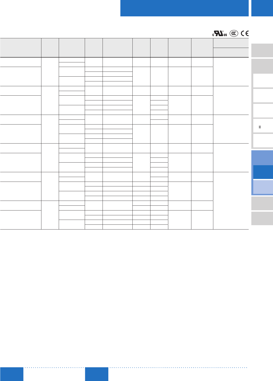
D-159
Brushless Motors/AC Speed Control Motors
D-159
Brushless
Motors
Overview,
Product
Series
AC Input
BMU
AC Input
BLE
AC Input
BLF
AC Input
BX
DC Input
BLH
DSC
BHF
AC Speed
Control
Motors
Accessories
Installation
CAD Data
Manuals www.orientalmotor.com Technical
Support TEL: (800) 468-3982
E-mail: techsupport@orientalmotor.com
■Specifications Continuous Rating✽1
Single-Phase 110/115 VAC, Single-Phase 220/230 VAC
Product Name
Max. Output
Power Voltage Frequency Variable Speed
Control Range✽2Current Power
Consumption Capacitor Motor Overheat
Protection
Device
Electromagnetic Brake
(Power off activated type)
Static Friction Torque
W (HP) VAC Hz r/min A W
F mN·m (oz-in)
DSCI26UAM-□
A -3V
6 (1/125)
Single-Phase 110 60 300 (90)∼1600 0.28 29 2.5 ZP
30 (4.2)
Single-Phase 115
DSCI26ECM-□
A -3V
Single-Phase 220 50 300 (90)∼1400
0.135 29 0.6 ZP
60 300 (90)∼1600
Single-Phase 230 50 300 (90)∼1400
60 300 (90)∼1600
DSCI315UAM-□
A -3V
15 (1/50)
Single-Phase 110 60 300 (90)∼1600 0.48 46 4.5 TP
80 (11.3)
Single-Phase 115
DSCI315ECM-□
A -3V
Single-Phase 220 50 300 (90)∼1400
0.23
43
1.0 TP
60 300 (90)∼1600 46
Single-Phase 230 50 300 (90)∼1400 44
60 300 (90)∼1600 47
DSCI425UAM-□
A -3V
25 (1/30)
Single-Phase 110 60 300 (90)∼1600 0.75 58 6.5 TP
100 (14.2)
Single-Phase 115 69
DSCI425ECM-□
A -3V
Single-Phase 220 50 300 (90)∼1400
0.37 70 1.5 TP
60 300 (90)∼1600
Single-Phase 230 50 300 (90)∼1400
60 300 (90)∼1600
DSCI540UAM-□
A -3V
40 (1/19)
Single-Phase 110 60 300 (90)∼1600 1.1 107 9.0 TP
200 (28)
Single-Phase 115
DSCI540ECM-□
A -3V
Single-Phase 220 50 300 (90)∼1400
0.55
96
2.3 TP
60 300 (90)∼1600 104
Single-Phase 230 50 300 (90)∼1400 99
60 300 (90)∼1600 105
DSCI560UAM-□
A -3V
60 (1/12)
Single-Phase 110 60 300 (90)∼1600 1.5 144 12 TP
500 (71)
Single-Phase 115 145
DSCI560ECM-□
A -3V
Single-Phase 220 50 300 (90)∼1400 0.71 129
3.0 TP
60 300 (90)∼1600 0.74 143
Single-Phase 230 50 300 (90)∼1400 0.72 132
60 300 (90)∼1600 0.74 144
DSCI590UAM-□
A -3V
90 (1/8)
Single-Phase 110 60 300 (90)∼1600 2.4 224 20 TP
Single-Phase 115 2.5 227
DSCI590ECM-□
A -3V
Single-Phase 220 50 300 (90)∼1400 1.2 201
6.0 TP
60 300 (90)∼1600 1.3 226
Single-Phase 230 50 300 (90)∼1400 1.2 204
60 300 (90)∼1600 1.3 228
✽1 When deceleration control is ON, the rated specifications will vary. For details, check "Common Specifications - Permissible continuous operation time while deceleration control is ON" ➜ Page D-160.
✽2 The value in ( ) can be set when deceleration control is OFF.
The specifications in the table are the characteristics of the motor on its own. The variable speed ranges shown are under no load conditions.
ZP: This indicates that these products are impedance protected. TP: This indicates that there is a built-in thermal protector (automatic return type).
A number indicating the gear ratio is entered where the box □ is located within the product name.

D-160
D-160 AC Speed Control Motors/DSC Series
ORIENTAL MOTOR GENERAL CATALOG
2015/2016 Page
Electromagnetic
Brake Type
Parallel Shaft
Features D-138 / System Configuration D-143 / Product Line D-157 / Specifications D-159 / Characteristics D-165
Dimensions D-166 / Connection and Operation D-171 / Motor and Driver Combinations D-170
■Common Specifications
Item Specifi cations
Speed Setting Methods
Setting can be performed using any of the following methods:
· Setting via Control Panel
A maximum of 4 patterns of operation data can be set.
· External Speed Potentiometer PAVR-20KZ (20 k
, 1/4 W)
· External DC Voltage: 0∼5 VDC, or 0∼10 VDC
Acceleration Time and Deceleration Time Setting Range 0.2∼15.0 seconds (0.0∼15.0 seconds: It can be set when the deceleration control is OFF.)
Acceleration time/deceleration time varies with the load condition of the motor.
Function
Monitor Mode Speed, operating data number, alarm code, warning code, I/O monitor
Data Mode Speed, acceleration time, deceleration time, reset
Parameter Mode
Gear ratio, speed increasing ratio, fi xed last digit display, initial operation inhibition alarm, external speed command input, external
speed command voltage selection, external speed control offset, speed upper and lower limit, deceleration control, brake type, input
function selection, output function selection, motor lock detection time, motor rotation direction, reset
Test Mode JOG operation, releasing of the electromagnetic brake
Others Data editing lock
Control Power Source 24 VDC±10% 0.15 A min.
Input Signals
Photocoupler Input Input Resistance 4.7 k
Arbitrary signal assignment to IN0∼IN5 input (6 points) is possible [ ]: Initial Setting
[FWD], [REV], [M0], [M1], [ALARM-RESET], [FREE], EXT-ERROR
Sink input/Source input··· Can be switched using the selection switch: Factory setting sink input
Output Signals
Photocoupler and Open-Collector Output External Power Supply 4.5∼30 VDC, 40 mA max.
Arbitrary signal assignment to OUT0, OUT1 output (2 points) is possible [ ]: Initial setting
[SPEED-OUT], [ALARM-OUT], TH-OUT, WNG
Sink Output/Source Output···Supports external wiring
Protective Function
When the following protective functions are activated, output to the motor is shut down, the electromagnetic brake is engaged and
the motor stops. The alarm output will be switched to OFF. At the same, the alarm code will be displayed on the control panel and the
ALARM LED will light up.
Alarm Types: Motor overheat, motor lock, overspeed, EEPROM error, initial operation inhibition, external stop
Permissible Continuous
Operation Time while
Deceleration Control is
ON
6 W (1/125 HP) Permissible Continuous Operation Time: Continuous
Operating Duty: Continuous
15 W (1/50 HP), 25 W (1/30 HP),
40 W (1/19 HP)
Permissible Continuous Operation Time: 1 minute
Operating Duty: 50% max. (Example: 1 minute operating, 1 minute stopped)
60 W (1/12 HP), 90 W (1/8 HP) Permissible Continuous Operation Time: 1 minute
Operating Duty: 33% max. (Example: 1 minute operating, 2 minutes stopped)
Max. Extension Distance Motor and Speed Controller Distance: 10.5 m (34.4 ft.) (when an accessory connection cable is used)
■General Specifications
Item Motor Speed Controller
Insulation Resistance
100 M or more when 500 VDC megger is applied between the windings
and the case after continuous operation under normal ambient temperature
and humidity.
100 M or more when 500 VDC megger is applied between the main
circuit terminal and the control circuit terminal, between the main circuit
terminal and the case, and between the main circuit terminal and FG after
continuous operation under normal ambient temperature and humidity.
Dielectric Strength
Suffi cient to withstand 1.5 kVAC at 50 Hz or 60 Hz applied between the
windings and the case for 1 minute after continuous operation under
normal ambient temperature and humidity.
Suffi cient to withstand 1.9 kVAC at 50 Hz or 60 Hz applied between the
main circuit terminal and the control circuit terminal and between the
main circuit terminal and the case, and 1.5 kVAC at 50 Hz or 60 Hz applied
between the main circuit terminal and FG for 1 minute after continuous
operation under normal ambient temperature and humidity.
Temperature Rise
Temperature rise of the winding temperature is 80˚C (144˚F) or less when
measured by the resistance change method after no-load continuous
operation under normal ambient temperature and humidity.
−
Overheat Protection Device The 6 W (1/125 HP) type is impedance protected.
All other motors have a built-in thermal protector (Automatic return type). −
Operating
Environment
Ambient
Temperature −10∼+40˚C (+14∼+104˚F) (Non-freezing) 0∼+40˚C (+32∼+104˚F) (Non-freezing)
Ambient Humidity 85% max. (Non-condensing)
Altitude Max. of 1000 m (3300 ft.) above sea level
Thermal Class 130 (B) −
Degree of Protection IP20 IP20
Note
Do not measure insulation resistance or perform the dielectric voltage test while the motor and speed controller are connected.
Standard Type
Parallel Shaft/
Round Shaft
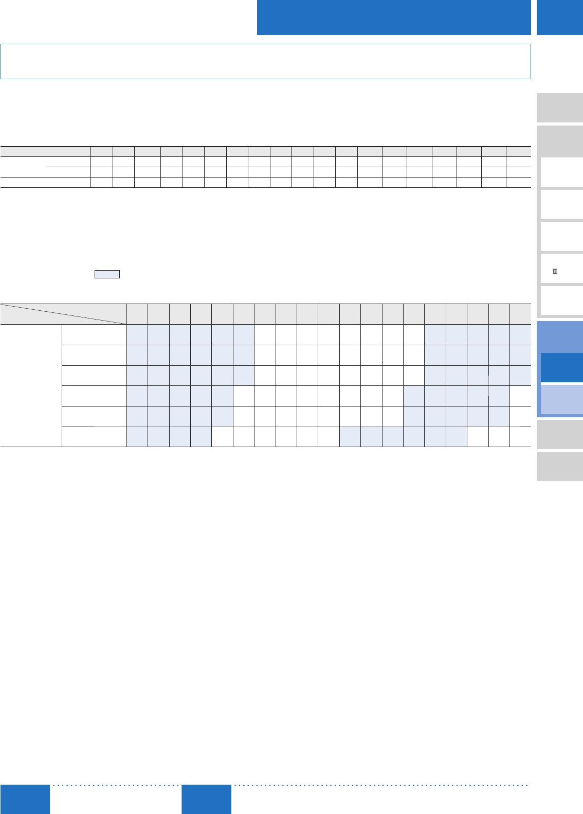
D-161
Brushless Motors/AC Speed Control Motors
D-161
Brushless
Motors
Overview,
Product
Series
AC Input
BMU
AC Input
BLE
AC Input
BLF
AC Input
BX
DC Input
BLH
DSC
BHF
AC Speed
Control
Motors
Accessories
Installation
CAD Data
Manuals www.orientalmotor.com Technical
Support TEL: (800) 468-3982
E-mail: techsupport@orientalmotor.com
Output Shaft Speed, Permissible Torque and Starting Torque while Deceleration Control
is ON (Factory setting)
Description of deceleration control ➜ Page D-158
■Output Shaft Rotation Speed
Motor Shaft Speed
Low Speed: 300 r/min, High Speed at 50 Hz: 1400 r/min, High Speed at 60 Hz: 1600 r/min Unit: r/min
Gear Ratio 7.5 9 12.5 15 18 25 30 36 50 60 75 90 100 120 150 180 250 300 360
High Speed 50 Hz 186 155 112 93 77 56 46 38 28 23 18.6 15.5 14 11.6 9.3 7.7 5.6 4.6 3.8
60 Hz 213 177 128 106 88 64 53 44 32 26 21 17.7 16 13.3 10.6 8.8 6.4 5.3 4.4
Low Speed 40 33 24 20 16 12 10 8.3 6 5 4 3.3 3 2.5 2 1.6 1.2 1 0.83
■Permissible Torque and Starting Torque
When within the variable speed range (50 Hz: 300∼1400 r/min, 60 Hz: 300∼1600 r/min), permissible torque and starting torque are a constant
value.
During horizontal operation, even when deceleration control is ON, the value is the same as when deceleration control is OFF. Permissible
torque and starting torque while deceleration control is OFF ➜ Page D-162
A colored background ( ) indicates gear shaft rotation in the same direction as the motor shaft, while the others rotate in the opposite
direction.
Unit: N·m (lb-in)
Gear Ratio
Product Name 7.5 9 12.5 15 18 25 30 36 50 60 75 90 100 120 150 180 250 300 360
Permissible Torque
Starting Torque
DSCI26UAM
DSCI26ECM
0.20 0.24 0.34 0.41 0.49 0.68 0.77 0.93 1.3 1.5 1.9 2.3 2.6 3.1 3.6 4.4 6 6 6
(1.77) (2.1) (3.0) (3.6) (4.3) (6.0) (6.8) (8.2) (11.5) (13.2) (16.8) (20) (23) (27) (31) (38) (53) (53) (53)
DSCI315UAM
DSCI315ECM
0.34 0.41 0.56 0.68 0.81 1.1 1.3 1.5 2.2 2.6 3.2 3.9 4.3 5.2 6.1 7.3 10 10 10
(3.0) (3.6) (4.9) (6.0) (7.1) (9.7) (11.5) (13.2) (19.4) (23) (28) (34) (38) (46) (53) (64) (88) (88) (88)
DSCI425UAM
DSCI425ECM
0.54 0.65 0.90 1.1 1.3 1.8 2.1 2.5 3.4 4.1 5.2 6.2 6.9 8.3 9.7 11.7 16 16 16
(4.7) (5.7) (7.9) (9.7) (11.5) (15.9) (18.5) (22) (30) (36) (46) (54) (61) (73) (85) (103) (141) (141) (141)
DSCI540UAM
DSCI540ECM
0.95 1.1 1.6 1.9 2.3 3.0 3.6 4.3 6.0 7.2 9.0 10.8 12.0 13.6 17.0 20.4 28.4 30 −
(8.4) (9.7) (14.1) (16.8) (20) (26) (31) (38) (53) (63) (79) (95) (106) (120) (150) (180) (250) (260)
DSCI560UAM
DSCI560ECM
1.4 1.7 2.4 2.8 3.4 4.5 5.4 6.5 9.0 10.8 13.5 16.3 18.1 20.4 25.5 30 30 30 −
(12.3) (15.0) (21) (24) (30) (39) (47) (57) (79) (95) (119) (144) (160) (180) (220) (260) (260) (260)
DSCI590UAM
DSCI590ECM
2.2 2.6 3.6 4.3 5.0 6.9 8.3 9.9 13.8 16.5 19.4 23.3 25.9 31.1 38.9 40 −−−
(19.4) (23) (31) (38) (44) (61) (73) (87) (122) (146) (171) (200) (220) (270) (340) (350)

D-162
D-162 AC Speed Control Motors/DSC Series
ORIENTAL MOTOR GENERAL CATALOG
2015/2016 Page
Electromagnetic
Brake Type
Parallel Shaft
Features D-138 / System Configuration D-143 / Product Line D-157 / Specifications D-159 / Characteristics D-165
Dimensions D-166 / Connection and Operation D-171 / Motor and Driver Combinations D-170
Output Shaft Speed, Permissible Torque and Starting Torque while Deceleration Control is OFF
Description of deceleration control ➜ Page D-158
■Output Shaft Rotation Speed
Motor Shaft Speed
Low Speed: 90 r/min, High Speed at 50 Hz: 1400 r/min, High Speed at 60 Hz: 1600 r/min Unit: r/min
Gear Ratio 7.5 9 12.5 15 18 25 30 36 50 60 75 90 100 120 150 180 250 300 360
High Speed 50 Hz 186 155 112 93 77 56 46 38 28 23 18.6 15.5 14 11.6 9.3 7.7 5.6 4.6 3.8
60 Hz 213 177 128 106 88 64 53 44 32 26 21 17.7 16 13.3 10.6 8.8 6.4 5.3 4.4
Low Speed 12 10 7.2 6 5 3.6 3 2.5 1.8 1.5 1.2 1 0.9 0.75 0.6 0.5 0.36 0.3 0.25
■Permissible Torque and Starting Torque
A colored background ( ) indicates gear shaft rotation in the same direction as the motor shaft, while the others rotate in the opposite
direction.
Single-Phase 110/115 VAC Unit: N·m (lb-in)
Product Name
Gear Ratio
7.5 9 12.5 15 18 25 30 36 50 60 75 90 100 120 150 180 250 300 360
Motor Shaft
Speed
r/min
DSCI26UAM
Permissible
1450 0.34 0.41 0.56 0.68 0.81 1.1 1.3 1.5 2.2 2.6 3.2 3.9 4.3 5.2 6 6 6 6 6
(3.0) (3.6) (4.9) (6.0) (7.1) (9.7) (11.5) (13.2) (19.4) (23) (28) (34) (38) (46) (53) (53) (53) (53) (53)
90 0.26 0.31 0.43 0.51 0.62 0.86 0.98 1.2 1.6 2.0 2.5 2.9 3.3 3.9 4.6 5.5 6 6 6
(2.3) (2.7) (3.8) (4.5) (5.4) (7.6) (8.6) (10.6) (14.1) (17.7) (22) (25) (29) (34) (40) (48) (53) (53) (53)
Starting 0.27 0.32 0.45 0.54 0.65 0.90 1.0 1.2 1.7 2.1 2.6 3.1 3.4 4.1 4.9 5.8 6 6 6
(2.3) (2.8) (3.9) (4.7) (5.7) (7.9) (8.8) (10.6) (15.0) (18.5) (23) (27) (30) (36) (43) (51) (53) (53) (53)
DSC315UAM
Permissible
1450
110 VAC 0.81 0.97 1.4 1.6 1.9 2.7 3.1 3.7 5.2 6.2 7.7 9.3 10 10 10 10 10 10 10
(7.1) (8.5) (12.3) (14.1) (16.8) (23) (27) (32) (46) (54) (68) (82) (88) (88) (88) (88) (88) (88) (88)
115 VAC 0.84 1.0 1.4 1.7 2.0 2.8 3.2 3.9 5.4 6.5 8.1 9.7 10 10 10 10 10 10 10
(7.4) (8.8) (12.3) (15.0) (17.7) (24) (28) (34) (47) (57) (71) (85) (88) (88) (88) (88) (88) (88) (88)
90 0.30 0.36 0.51 0.61 0.73 1.0 1.2 1.4 1.9 2.3 2.9 3.5 3.9 4.6 5.5 6.6 9.1 10 10
(2.6) (3.1) (4.5) (5.3) (6.4) (8.8) (10.6) (12.3) (16.8) (20) (25) (30) (34) (40) (48) (58) (80) (88) (88)
Starting
110 VAC 0.57 0.68 0.95 1.1 1.4 1.9 2.2 2.6 3.6 4.3 5.4 6.5 7.2 8.7 10 10 10 10 10
(5.0) (6.0) (8.4) (9.7) (12.3) (16.8) (19.4) (23) (31) (38) (47) (57) (63) (76) (88) (88) (88) (88) (88)
115 VAC 0.61 0.73 1.0 1.2 1.5 2.0 2.3 2.8 3.9 4.6 5.8 7.0 7.7 9.3 10 10 10 10 10
(5.3) (6.4) (8.8) (10.6) (13.2) (17.7) (20) (24) (34) (40) (51) (61) (68) (82) (88) (88) (88) (88) (88)
DSCI425UAM
Permissible
1450 1.4 1.7 2.3 2.8 3.3 4.6 5.3 6.3 8.8 10.6 13.2 15.9 16 16 16 16 16 16 16
(12.3) (15.0) (20) (24) (29) (40) (46) (55) (77) (93) (116) (140) (141) (141) (141) (141) (141) (141) (141)
90 0.30 0.36 0.51 0.61 0.73 1.0 1.2 1.4 1.9 2.3 2.9 3.5 3.9 4.6 5.5 6.6 9.1 10.9 13.1
(2.6) (3.1) (4.5) (5.3) (6.4) (8.8) (10.6) (12.3) (16.8) (20) (25) (30) (34) (40) (48) (58) (80) (96) (115)
Starting
110 VAC 0.84 1.0 1.4 1.7 2.0 2.8 3.2 3.9 5.4 6.5 8.1 9.7 10.8 12.9 15.2 16 16 16 16
(7.4) (8.8) (12.3) (15.0) (17.7) (24) (28) (34) (47) (57) (71) (85) (95) (114) (134) (141) (141) (141) (141)
115 VAC 0.91 1.1 1.5 1.8 2.2 3.0 3.5 4.2 5.8 7.0 8.7 10.4 11.6 13.9 16 16 16 16 16
(8.0) (9.7) (13.2) (15.9) (19.4) (26) (30) (37) (51) (61) (76) (92) (102) (123) (141) (141) (141) (141) (141)
DSCI540UAM
Permissible
1450 2.2 2.6 3.6 4.3 5.2 6.9 8.3 9.9 13.8 16.5 20.6 24.8 27.5 30 30 30 30 30 −
(19.4) (23) (31) (38) (46) (61) (73) (87) (122) (146) (182) (210) (240) (260) (260) (260) (260) (260)
90 0.47 0.57 0.79 0.95 1.1 1.5 1.8 2.2 3.0 3.6 4.5 5.4 6.0 6.8 8.5 10.2 14.2 17 −
(4.1) (5.0) (6.9) (8.4) (9.7) (13.2) (15.9) (19.4) (26) (31) (39) (47) (53) (60) (75) (90) (125) (150)
Starting
110 VAC 1.2 1.5 2.0 2.4 2.9 3.9 4.6 5.6 7.7 9.3 11.6 13.9 15.5 17.5 21.9 26.2 30 30 −
(10.6) (13.2) (17.7) (21) (25) (34) (40) (49) (68) (82) (102) (123) (137) (154) (193) (230) (260) (260)
115 VAC 1.3 1.5 2.1 2.6 3.1 4.1 4.9 5.9 8.2 9.8 12.3 14.7 16.3 18.5 23.1 27.7 30 30 −
(11.5) (13.2) (18.5) (23) (27) (36) (43) (52) (72) (86) (108) (130) (144) (163) (200) (240) (260) (260)
DSCI560UAM
Permissible
1450
110 VAC 3.1 3.7 5.2 6.2 7.5 9.9 11.9 14.2 19.8 23.7 29.7 30 30 30 30 30 30 30 −
(27) (32) (46) (54) (66) (87) (105) (125) (175) (200) (260) (260) (260) (260) (260) (260) (260) (260)
115 VAC 3.3 4.0 5.5 6.6 7.9 10.5 12.6 15.2 21.1 25.3 30 30 30 30 30 30 30 30 −
(29) (35) (48) (58) (69) (92) (111) (134) (186) (220) (260) (260) (260) (260) (260) (260) (260) (260)
90 0.54 0.65 0.90 1.1 1.3 1.7 2.1 2.5 3.4 4.1 5.2 6.2 6.9 7.8 9.7 11.7 16.2 19.4 −
(4.7) (5.7) (7.9) (9.7) (11.5) (15.0) (18.5) (22) (30) (36) (46) (54) (61) (69) (85) (103) (143) (171)
Starting
110 VAC 1.8 2.1 2.9 3.5 4.2 5.6 6.7 8.0 11.2 13.4 16.8 20.1 22.4 25.3 30 30 30 30 −
(15.9) (18.5) (25) (30) (37) (49) (59) (70) (99) (118) (148) (177) (198) (220) (260) (260) (260) (260)
115 VAC 1.9 2.3 3.2 3.8 4.5 6.0 7.2 8.7 12.0 14.4 18.1 21.7 24.1 27.2 30 30 30 30 −
(16.8) (20) (28) (33) (39) (53) (63) (76) (106) (127) (160) (192) (210) (240) (260) (260) (260) (260)
DSCI590UAM
Permissible
1450 4.9 5.9 8.2 9.9 11.3 15.7 18.8 22.6 31.4 37.7 40 40 40 40 40 40 −−−
(43) (52) (72) (87) (100) (138) (166) (200) (270) (330) (350) (350) (350) (350) (350) (350)
90 0.57 0.69 0.96 1.1 1.3 1.8 2.2 2.6 3.7 4.4 5.2 6.2 6.9 8.3 10.3 12.4 −−−
(5.0) (6.1) (8.4) (9.7) (11.5) (15.9) (19.4) (23) (32) (38) (46) (54) (61) (73) (91) (109)
Starting
110 VAC 2.7 3.2 4.5 5.4 6.2 8.6 10.3 12.4 17.2 20.6 24.3 29.2 32.4 38.9 40 40 −−−
(23) (28) (39) (47) (54) (76) (91) (109) (152) (182) (210) (250) (280) (340) (350) (350)
115 VAC 3.0 3.6 5.0 5.9 6.8 9.5 11.4 13.6 18.9 22.7 26.7 32.1 35.6 40 40 40 −−−
(26) (31) (44) (52) (60) (84) (100) (120) (167) (200) (230) (280) (310) (350) (350) (350)
Standard Type
Parallel Shaft/
Round Shaft

D-163
Brushless Motors/AC Speed Control Motors
D-163
Brushless
Motors
Overview,
Product
Series
AC Input
BMU
AC Input
BLE
AC Input
BLF
AC Input
BX
DC Input
BLH
DSC
BHF
AC Speed
Control
Motors
Accessories
Installation
CAD Data
Manuals www.orientalmotor.com Technical
Support TEL: (800) 468-3982
E-mail: techsupport@orientalmotor.com
Output Shaft Speed, Permissible Torque and Starting Torque while Deceleration Control is OFF
Description of deceleration control ➜ Page D-158
Single-Phase 220/230 VAC Unit: N·m (lb-in)
Product Name
Gear Ratio
7.5 9 12.5 15 18 25 30 36 50 60 75 90 100 120 150 180 250 300 360
Motor Shaft Speed
r/min
DSCI26ECM
Permissible
1200
220 VAC
50 Hz
0.28
(2.4)
0.34
(3.0)
0.47
(4.1)
0.57
(5.0)
0.68
(6.0)
0.95
(8.4)
1.1
(9.7)
1.3
(11.5)
1.8
(15.9)
2.2
(19.4)
2.7
(23)
3.3
(29)
3.6
(31)
4.3
(38)
5.1
(45)
6
(53)
6
(53)
6
(53)
6
(53)
230 VAC
50 Hz
0.31
(2.7)
0.37
(3.2)
0.52
(4.6)
0.62
(5.4)
0.75
(6.6)
1.0
(8.8)
1.2
(10.6)
1.4
(12.3)
2.0
(17.7)
2.4
(21)
3.0
(26)
3.6
(31)
4.0
(35)
4.7
(41)
5.6
(49)
6
(53)
6
(53)
6
(53)
6
(53)
1450
220 VAC
60 Hz
0.31
(2.7)
0.37
(3.2)
0.52
(4.6)
0.62
(5.4)
0.75
(6.6)
1.0
(8.8)
1.2
(10.6)
1.4
(12.3)
2.0
(17.7)
2.4
(21)
3.0
(26)
3.6
(31)
4.0
(35)
4.7
(41)
5.6
(49)
6
(53)
6
(53)
6
(53)
6
(53)
230 VAC
60 Hz
0.34
(3.0)
0.41
(3.6)
0.56
(4.9)
0.68
(6.0)
0.81
(7.1)
1.1
(9.7)
1.3
(11.5)
1.5
(13.2)
2.2
(19.4)
2.6
(23)
3.2
(28)
3.9
(34)
4.3
(38)
5.2
(46)
6
(53)
6
(53)
6
(53)
6
(53)
6
(53)
90
220 VAC
50/60 Hz
0.27
(2.3)
0.32
(2.8)
0.45
(3.9)
0.54
(4.7)
0.65
(5.7)
0.90
(7.9)
1.0
(8.8)
1.2
(10.6)
1.7
(15.0)
2.1
(18.5)
2.6
(23)
3.1
(27)
3.4
(30)
4.1
(36)
4.9
(43)
5.8
(51)
6
(53)
6
(53)
6
(53)
230 VAC
50 Hz
0.25
(2.2)
0.30
(2.6)
0.42
(3.7)
0.50
(4.4)
0.60
(5.3)
0.83
(7.3)
0.95
(8.4)
1.1
(9.7)
1.6
(14.1)
1.9
(16.8)
2.4
(21)
2.9
(25)
3.2
(28)
3.8
(33)
4.5
(39)
5.4
(47)
6
(53)
6
(53)
6
(53)
230 VAC
60 Hz
0.26
(2.3)
0.32
(2.8)
0.44
(3.8)
0.53
(4.6)
0.63
(5.5)
0.88
(7.7)
1.0
(8.8)
1.2
(10.6)
1.7
(15.0)
2.0
(17.7)
2.5
(22)
3.0
(26)
3.4
(30)
4.0
(35)
4.7
(41)
5.7
(50)
6
(53)
6
(53)
6
(53)
Starting
220 VAC
50/60 Hz
0.30
(2.6)
0.36
(3.1)
0.50
(4.4)
0.59
(5.2)
0.71
(6.2)
0.99
(8.7)
1.1
(9.7)
1.4
(12.3)
1.9
(16.8)
2.3
(20)
2.8
(24)
3.4
(30)
3.8
(33)
4.5
(39)
5.3
(46)
6
(53)
6
(53)
6
(53)
6
(53)
230 VAC
50 Hz
0.30
(2.6)
0.36
(3.1)
0.50
(4.4)
0.59
(5.2)
0.71
(6.2)
0.99
(8.7)
1.1
(9.7)
1.4
(12.3)
1.9
(16.8)
2.3
(20)
2.8
(24)
3.4
(30)
3.8
(33)
4.5
(39)
5.3
(46)
6
(53)
6
(53)
6
(53)
6
(53)
230 VAC
60 Hz
0.34
(3.0)
0.41
(3.6)
0.56
(4.9)
0.68
(6.0)
0.81
(7.1)
1.1
(9.7)
1.3
(11.5)
1.5
(13.2)
2.2
(19.4)
2.6
(23)
3.2
(28)
3.9
(34)
4.3
(38)
5.2
(46)
6
(53)
6
(53)
6
(53)
6
(53)
6
(53)
DSCI315ECM
Permissible
1200 50 Hz 0.84
(7.4)
1.0
(8.8)
1.4
(12.3)
1.7
(15.0)
2.0
(17.7)
2.8
(24)
3.2
(28)
3.9
(34)
5.4
(47)
6.5
(57)
8.1
(71)
9.7
(85)
10
(88)
10
(88)
10
(88)
10
(88)
10
(88)
10
(88)
10
(88)
1450
220 VAC
60 Hz
0.74
(6.5)
0.89
(7.8)
1.2
(10.6)
1.5
(13.2)
1.8
(15.9)
2.5
(22)
2.8
(24)
3.4
(30)
4.7
(41)
5.7
(50)
7.1
(62)
8.5
(75)
9.5
(84)
10
(88)
10
(88)
10
(88)
10
(88)
10
(88)
10
(88)
230 VAC
60 Hz
0.81
(7.1)
0.97
(8.5)
1.4
(12.3)
1.6
(14.1)
1.9
(16.8)
2.7
(23)
3.1
(27)
3.7
(32)
5.2
(46)
6.2
(54)
7.7
(68)
9.3
(82)
10
(88)
10
(88)
10
(88)
10
(88)
10
(88)
10
(88)
10
(88)
90 0.27
(2.3)
0.32
(2.8)
0.45
(3.9)
0.54
(4.7)
0.65
(5.7)
0.90
(7.9)
1.0
(8.8)
1.2
(10.6)
1.7
(15.0)
2.1
(18.5)
2.6
(23)
3.1
(27)
3.4
(30)
4.1
(36)
4.9
(43)
5.8
(51)
8.1
(71)
9.7
(85)
10
(88)
Starting
220 VAC
50/60 Hz
0.45
(3.9)
0.54
(4.7)
0.75
(6.6)
0.90
(7.9)
1.1
(9.7)
1.5
(13.2)
1.7
(15.0)
2.1
(18.5)
2.9
(25)
3.5
(30)
4.3
(38)
5.2
(46)
5.8
(51)
6.9
(61)
8.1
(71)
9.8
(86)
10
(88)
10
(88)
10
(88)
230 VAC
50 Hz
0.49
(4.3)
0.58
(5.1)
0.81
(7.1)
0.97
(8.5)
1.2
(10.6)
1.6
(14.1)
1.9
(16.8)
2.2
(19.4)
3.1
(27)
3.7
(32)
4.6
(40)
5.6
(49)
6.2
(54)
7.4
(65)
8.7
(76)
10
(88)
10
(88)
10
(88)
10
(88)
230 VAC
60 Hz
0.55
(4.8)
0.66
(5.8)
0.91
(8.0)
1.1
(9.7)
1.3
(11.5)
1.8
(15.9)
2.1
(18.5)
2.5
(22)
3.5
(30)
4.2
(37)
5.2
(46)
6.3
(55)
7.0
(61)
8.4
(74)
9.8
(86)
10
(88)
10
(88)
10
(88)
10
(88)
DSCI425ECM
Permissible
1200 50 Hz 1.4
(12.3)
1.7
(15.0)
2.3
(20)
2.8
(24)
3.3
(29)
4.6
(40)
5.3
(46)
6.3
(55)
8.8
(77)
10.6
(93)
13.2
(116)
15.9
(140)
16
(141)
16
(141)
16
(141)
16
(141)
16
(141)
16
(141)
16
(141)
1450 60 Hz 1.4
(12.3)
1.7
(15.0)
2.3
(20)
2.8
(24)
3.3
(29)
4.6
(40)
5.3
(46)
6.3
(55)
8.8
(77)
10.6
(93)
13.2
(116)
15.9
(140)
16
(141)
16
(141)
16
(141)
16
(141)
16
(141)
16
(141)
16
(141)
90 0.27
(2.3)
0.32
(2.8)
0.45
(3.9)
0.54
(4.7)
0.65
(5.7)
0.90
(7.9)
1.0
(8.8)
1.2
(10.6)
1.7
(15.0)
2.1
(18.5)
2.6
(23)
3.1
(27)
3.4
(30)
4.1
(36)
4.9
(43)
5.8
(51)
8.1
(71)
9.7
(85)
11.7
(103)
Starting
220 VAC
50/60 Hz
0.74
(6.5)
0.89
(7.8)
1.2
(10.6)
1.5
(13.2)
1.8
(15.9)
2.5
(22)
2.8
(24)
3.4
(30)
4.7
(41)
5.7
(50)
7.1
(62)
8.5
(75)
9.5
(84)
11.4
(100)
13.4
(118)
16
(141)
16
(141)
16
(141)
16
(141)
230 VAC
50/60 Hz
0.81
(7.1)
0.97
(8.5)
1.4
(12.3)
1.6
(14.1)
1.9
(16.8)
2.7
(23)
3.1
(27)
3.7
(32)
5.2
(46)
6.2
(54)
7.7
(68)
9.3
(82)
10.3
(91)
12.4
(109)
14.6
(129)
16
(141)
16
(141)
16
(141)
16
(141)
DSCI540ECM
Permissible
1200 50 Hz 2.2
(19.4)
2.6
(23)
3.6
(31)
4.3
(38)
5.2
(46)
6.9
(61)
8.3
(73)
9.9
(87)
13.8
(122)
16.5
(146)
20.6
(182)
24.8
(210)
27.5
(240)
30
(260)
30
(260)
30
(260)
30
(260)
30
(260) −
1450 60 Hz 2.2
(19.4)
2.6
(23)
3.6
(31)
4.3
(38)
5.2
(46)
6.9
(61)
8.3
(73)
9.9
(87)
13.8
(122)
16.5
(146)
20.6
(182)
24.8
(210)
27.5
(240)
30
(260)
30
(260)
30
(260)
30
(260)
30
(260) −
90
50 Hz 0.44
(3.8)
0.53
(4.6)
0.73
(6.4)
0.88
(7.7)
1.1
(9.7)
1.4
(12.3)
1.7
(15.0)
2.0
(17.7)
2.8
(24)
3.4
(30)
4.2
(37)
5.0
(44)
5.6
(49)
6.3
(55)
7.9
(69)
9.5
(84)
13.2
(116)
15.8
(139) −
60 Hz 0.47
(4.1)
0.57
(5.0)
0.79
(6.9)
0.95
(8.4)
1.1
(9.7)
1.5
(13.2)
1.8
(15.9)
2.2
(19.4)
3.0
(26)
3.6
(31)
4.5
(39)
5.4
(47)
6.0
(53)
6.8
(60)
8.5
(75)
10.2
(90)
14.2
(125)
17
(150) −
Starting 1.3
(11.5)
1.5
(13.2)
2.1
(18.5)
2.6
(23)
3.1
(27)
4.1
(36)
4.9
(43)
5.9
(52)
8.2
(72)
9.8
(86)
12.3
(108)
14.7
(130)
16.3
(144)
18.5
(163)
23.1
(200)
27.7
(240)
30
(260)
30
(260) −

D-164
D-164 AC Speed Control Motors/DSC Series
ORIENTAL MOTOR GENERAL CATALOG
2015/2016 Page
Electromagnetic
Brake Type
Parallel Shaft
Features D-138 / System Configuration D-143 / Product Line D-157 / Specifications D-159 / Characteristics D-165
Dimensions D-166 / Connection and Operation D-171 / Motor and Driver Combinations D-170
Product Name
Gear Ratio
7.5 9 12.5 15 18 25 30 36 50 60 75 90 100 120 150 180 250 300 360
Motor Shaft Speed
r/min
DSCI560ECM
Permissible
1200 50 Hz 3.3
(29)
4.0
(35)
5.5
(48)
6.6
(58)
7.9
(69)
10.5
(92)
12.6
(111)
15.2
(134)
21.1
(186)
25.3
(220)
30
(260)
30
(260)
30
(260)
30
(260)
30
(260)
30
(260)
30
(260)
30
(260) −
1450
220 VAC
60 Hz
3.1
(27)
3.7
(32)
5.2
(46)
6.2
(54)
7.5
(66)
9.9
(87)
11.9
(105)
14.2
(125)
19.8
(175)
23.7
(200)
29.7
(260)
30
(260)
30
(260)
30
(260)
30
(260)
30
(260)
30
(260)
30
(260) −
230 VAC
60 Hz
3.3
(29)
4.0
(35)
5.5
(48)
6.6
(58)
7.9
(69)
10.5
(92)
12.6
(111)
15.2
(134)
21.1
(186)
25.3
(220)
30
(260)
30
(260)
30
(260)
30
(260)
30
(260)
30
(260)
30
(260)
30
(260) −
90
220 VAC
50 Hz
0.54
(4.7)
0.65
(5.7)
0.90
(7.9)
1.1
(9.7)
1.3
(11.5)
1.7
(15.0)
2.1
(18.5)
2.5
(22)
3.4
(30)
4.1
(36)
5.2
(46)
6.2
(54)
6.9
(61)
7.8
(69)
9.7
(85)
11.7
(103)
16.2
(143)
19.4
(171) −
220 VAC
60 Hz
0.51
(4.5)
0.61
(5.3)
0.84
(7.4)
1.0
(8.8)
1.2
(10.6)
1.6
(14.1)
1.9
(16.8)
2.3
(20)
3.2
(28)
3.9
(34)
4.8
(42)
5.8
(51)
6.5
(57)
7.3
(64)
9.1
(80)
10.9
(96)
15.2
(134)
18.2
(161) −
230 VAC
50 Hz
0.57
(5.0)
0.69
(6.1)
0.96
(8.4)
1.1
(9.7)
1.4
(12.3)
1.8
(15.9)
2.2
(19.4)
2.6
(23)
3.7
(32)
4.4
(38)
5.5
(48)
6.6
(58)
7.3
(64)
8.3
(73)
10.3
(91)
12.4
(109)
17.2
(152)
20.7
(183) −
230 VAC
60 Hz
0.54
(4.7)
0.65
(5.7)
0.90
(7.9)
1.1
(9.7)
1.3
(11.5)
1.7
(15.0)
2.1
(18.5)
2.5
(22)
3.4
(30)
4.1
(36)
5.2
(46)
6.2
(54)
6.9
(61)
7.8
(69)
9.7
(85)
11.7
(103)
16.2
(143)
19.4
(171) −
Starting
220 VAC
50 Hz
1.9
(16.8)
2.3
(20)
3.2
(28)
3.8
(33)
4.5
(39)
6.0
(53)
7.2
(63)
8.7
(76)
12.0
(106)
14.4
(127)
18.1
(160)
21.7
(192)
24.1
(210)
27.2
(240)
30
(260)
30
(260)
30
(260)
30
(260) −
220 VAC
60 Hz
2.0
(17.7)
2.3
(20)
3.3
(29)
3.9
(34)
4.7
(41)
6.2
(54)
7.5
(66)
9.0
(79)
12.5
(110)
15.0
(132)
18.7
(165)
22.4
(198)
24.9
(220)
28.2
(240)
30
(260)
30
(260)
30
(260)
30
(260) −
230 VAC
50 Hz
2.0
(17.7)
2.3
(20)
3.3
(29)
3.9
(34)
4.7
(41)
6.2
(54)
7.5
(66)
9.0
(79)
12.5
(110)
15.0
(132)
18.7
(165)
22.4
(198)
24.9
(220)
28.2
(240)
30
(260)
30
(260)
30
(260)
30
(260) −
230 VAC
60 Hz
2.0
(17.7)
2.4
(21)
3.4
(30)
4.1
(36)
4.9
(43)
6.5
(57)
7.7
(68)
9.3
(82)
12.9
(114)
15.5
(137)
19.4
(171)
23.2
(200)
25.8
(220)
29.2
(250)
30
(260)
30
(260)
30
(260)
30
(260) −
DSCI590ECM
Permissible
1200 50 Hz 4.9
(43)
5.9
(52)
8.2
(72)
9.9
(87)
11.3
(100)
15.7
(138)
18.8
(166)
22.6
(200)
31.4
(270)
37.7
(330)
40
(350)
40
(350)
40
(350)
40
(350)
40
(350)
40
(350) −−−
1450 60 Hz 4.9
(43)
5.9
(52)
8.2
(72)
9.9
(87)
11.3
(100)
15.7
(138)
18.8
(166)
22.6
(200)
31.4
(270)
37.7
(330)
40
(350)
40
(350)
40
(350)
40
(350)
40
(350)
40
(350) −−−
90 0.64
(5.6)
0.77
(6.8)
1.1
(9.7)
1.3
(11.5)
1.5
(13.2)
2.0
(17.7)
2.5
(22)
2.9
(25)
4.1
(36)
4.9
(43)
5.8
(51)
6.9
(61)
7.7
(68)
9.2
(81)
11.5
(101)
13.9
(123) −−−
Starting
220 VAC
50 Hz
3.3
(29)
4.0
(35)
5.5
(48)
6.6
(58)
7.6
(67)
10.5
(92)
12.6
(111)
15.2
(134)
21.1
(186)
25.3
(220)
29.8
(260)
35.7
(310)
39.7
(350)
40
(350)
40
(350)
40
(350) −−−
220 VAC
60 Hz
3.4
(30)
4.1
(36)
5.6
(49)
6.8
(60)
7.7
(68)
10.8
(95)
12.9
(114)
15.5
(137)
21.5
(190)
25.8
(220)
30.4
(260)
36.5
(320)
40
(350)
40
(350)
40
(350)
40
(350) −−−
230 VAC
50 Hz
3.5
(30)
4.2
(37)
5.9
(52)
7.0
(61)
8.0
(70)
11.2
(99)
13.4
(118)
16.1
(142)
22.4
(198)
26.8
(230)
31.6
(270)
37.9
(330)
40
(350)
40
(350)
40
(350)
40
(350) −−−
230 VAC
60 Hz
3.6
(31)
4.3
(38)
6.0
(53)
7.2
(63)
8.2
(72)
11.4
(100)
13.7
(121)
16.4
(145)
22.8
(200)
27.3
(240)
32.2
(280)
38.6
(340)
40
(350)
40
(350)
40
(350)
40
(350) −−−
Unit: N·m (lb-in)
■ Permissible Radial Load and Permissible Axial Load
➜Page D-148
■Permissible Inertia J
➜Page D-148
Standard Type
Parallel Shaft/
Round Shaft
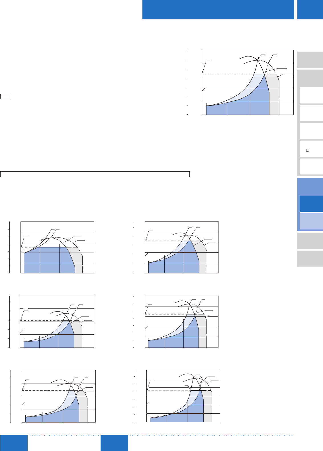
D-165
Brushless Motors/AC Speed Control Motors
D-165
Brushless
Motors
Overview,
Product
Series
AC Input
BMU
AC Input
BLE
AC Input
BLF
AC Input
BX
DC Input
BLH
DSC
BHF
AC Speed
Control
Motors
Accessories
Installation
CAD Data
Manuals www.orientalmotor.com Technical
Support TEL: (800) 468-3982
E-mail: techsupport@orientalmotor.com
■How to Read Speed – Torque Characteristics
The characteristics on the right shows the relationship between each setting speed
and torque when a speed control motor is operated.
① 50 Hz Safe-Operation Line ② 60 Hz Safe-Operation Line
The safe-operation line is the permissible line of torque that is limited by the motor's
permissible temperature.
Motors can be operated at the continuous rating within the safe-operation line.
The safe-operation line is determined under the most severe condition where there is
no heat conduction. Therefore, depending on the installation conditions of the motor,
it can be operated beyond the safe-operation line.
Note
When operating beyond the safe-operation line, make sure the motor case temperature is kept at 90˚C (194°F) or less.
③ Starting Torque
This refers to the degree of torque with which the motor can start.
④ Permissible Torque on Combination Types
This refers to the permissible value of the motor torque when operating with the
gearhead installed.
Because the permissible torque of the combination type varies according to the gear
ratio, use the motor without exceeding the value on the list of permissible torques.
14001000
500
01600
0.1
0.2
0.3
0.4
0.5 ①②
50 Hz
60 Hz
③
90
④
Torque [N·m]
Speed [r/min]
0
Torque [oz-in]
70
60
50
40
30
20
10
■Speed – Torque Characteristics (Reference values)
② 60 Hz Safe-Operation Line
① 50 Hz Safe-Operation Line ③ Starting Torque ④ Permissible Torque on Combination Types
All output characteristics are representative values. (For motor only)
The permissible torque and starting torque of the motor vary according to the voltage. Use after checking the specifications and permissible
torque of the combination type.
The characteristics diagram is when used while the deceleration control is OFF.
When using while the deceleration control is ON, check the permissible torque value. Permissible torque ➜ Page D-161
6 W (1/125 HP) 15 W (1/50 HP)
14001000
500 1600
20
0
40
60
80
100
50 Hz
60 Hz
①②
③
90
④
Torque [mN·m]
0
Torque [oz-in]
14
12
10
8
6
4
2
Speed [r/min]
14001000500
01600
40
80
120
160
200
Speed [r/min]
50 Hz
60 Hz
①②
③
90
④
Torque [mN·m]
0
Torque [oz-in]
25
20
15
10
5
25 W (1/30 HP) 40 W (1/19 HP)
14001000500 1600
0.1
0
0.2
0.3
0.4
①②
60 Hz
50 Hz
③
90
④
Torque [N·m]
Speed [r/min]
0
Torque [oz-in]
50
40
30
20
10
14001000
500
01600
0.1
0.2
0.3
0.4
0.5 ①②
50 Hz
60 Hz
③
90
④
Torque [N·m]
Speed [r/min]
0
Torque [oz-in]
70
60
50
40
30
20
10
60 W (1/12 HP) 90 W (1/8 HP)
14001000500
01600
0.2
0.4
0.6
0.8
50 Hz
60 Hz
③
②①
90
④
Torque [N·m]
Speed [r/min]
0
Torque [oz-in]
100
80
60
40
20
140010005000 1600
①
②50 Hz
60 Hz
③
0.2
0.4
0.6
0.8
1.0
1.2
90
④
Torque [N·m]
Torque [oz-in]
150
125
100
75
50
25
Speed [r/min]
0

D-166
D-166 AC Speed Control Motors/DSC Series
ORIENTAL MOTOR GENERAL CATALOG
2015/2016 Page
Electromagnetic
Brake Type
Parallel Shaft
Features D-138 / System Configuration D-143 / Product Line D-157 / Specifications D-159 / Characteristics D-165
Dimensions D-166 / Connection and Operation D-171 / Motor and Driver Combinations D-170
■Dimensions Unit = mm (in.)
"Installation screws" are included with the combination type. Dimensions of installation screws ➜ Page C-215
A number indicating the gear ratio is entered where the box □ is located within the product name.
Combination Type
6 W (1/125 HP)
Product Name Motor Product Name Gearhead
Product Name Gear Ratio L Mass
kg (lb.) 2D CAD
DSCI26UAM-□A -3V
DSCI26ECM-□A -3V
2IK6UGV-UAM
2IK6UGV-ECM 2GV□ A
7.5∼25 34 (1.34) 1.7
(3.7)
A1407A
30∼120 38 (1.50) A1407B
150∼360 43 (1.69) A1407C
10
(0.39)
47
(1.85)
118 (4.65)
A
A
500 (20)
15
(0.59)
22.5°
L
7
(0.28)
60 (2.36)
26.5
(1.04)
10±0.5
(0.39±0.02)
4
(0.16)
[
0.3750−0.0005 (3/8”)
]
0
32±1
23−0.021
0
0.0000
0.0000
(1.26±0.04)
9.525−0.013
(
0.9055−0.0008
)
25
(0.98)
60
(2.36)
60
(2.36)
70
±0.5
(2.76
±0.02
)
5 max.
(0.20 max.)
21.5
(0.85)
15.5
(0.61)
2.383−0.025
(
0.0938−0.0010
)
0
0.0000
2.383−0.025
(
0.0938−0.0010
)
0
25±0.2
(0.984±0.008)
0.0000
2.383 0
(
0.0938
)
+0.040
+0.0016
0.0000
1.321
(
0.052
)
+0.381
+0.015
0.000
0
5557-06R-210 (MOLEX)
51103-0300 (MOLEX)
Tube 11 (0.43)
4×4.5
(0.177) Thru
Detail Drawing of Protective Earth Terminal
Protective Earth Terminal M4
Parallel Key (Included) A-A
15 W (1/50 HP)
Product Name Motor Product Name Gearhead
Product Name Gear Ratio L Mass
kg (lb.) 2D CAD
DSCI315UAM-□A -3V
DSCI315ECM-□A -3V
3IK15UGV-UAM
3IK15UGV-ECM 3GV□ A
7.5∼25 38 (1.50) 2.2
(4.8)
A1408A
30∼120 43 (1.69) A1408B
150∼360 48 (1.89) A1408C
10
(0.39)
A
A
500 (20)
15
(0.59)
22.5°
L
123 (4.84)
7
(0.28)
32±1
(1.26±0.04)
25
(0.98)
26.5
(1.04)
12.7−0.013
0.0000
0
[
0.5000−0.0005 (1/2”)
]
4.5
(0.18)
12±0.5
(0.47±0.02)
31−0.025
0
0.0000
(
1.2205−0.0010
)
3.175−0.025
25±0.2
(0.984±0.008)
(
0.070 0.000
)
+0.381
+0.015
3.175 0
+0.040
+0.0016
(
0.1250−0.0010
)
0.0000
01.778 0
(
0.1250 0.0000
)
3.175−0.025
0
0.0000
(
0.1250−0.0010
)
70
(2.76)
70
(2.76)
5 max.
(0.20 max.)
82
±0.5
(3.23
±0.02
)
21.5
(0.85)
16.5
(0.65)
70
(2.76)
47
(1.85)
51103-0300 (MOLEX)
5557-06R-210 (MOLEX)
Tube 11 (0.43)
Parallel Key (Included)A-A
4×6.5
(0.256) Thru
Detail Drawing of Protective Earth Terminal
Protective Earth Terminal M4
Standard Type
Parallel Shaft/
Round Shaft

D-167
Brushless Motors/AC Speed Control Motors
D-167
Brushless
Motors
Overview,
Product
Series
AC Input
BMU
AC Input
BLE
AC Input
BLF
AC Input
BX
DC Input
BLH
DSC
BHF
AC Speed
Control
Motors
Accessories
Installation
CAD Data
Manuals www.orientalmotor.com Technical
Support TEL: (800) 468-3982
E-mail: techsupport@orientalmotor.com
25 W (1/30 HP)
Product Name Motor Product Name Gearhead
Product Name Gear Ratio L Mass
kg (lb.) 2D CAD
DSCI425UAM-□A -3V
DSCI425ECM-□A -3V
4IK25UGV-UAM
4IK25UGV-ECM 4GV□ A
7.5∼25 41 (1.61) 3.25
(7.2)
A1409A
30∼120 46 (1.81) A1409B
150∼360 51 (2.01) A1409C
L
6.5
(0.26)
7
(0.28)
134 (5.28)
9
(0.35)
47
(1.85)
80 (3.15)
25
(0.98)
27
(1.06)
A
A
500 (20)
15
(
0.59
)
22.5°
13±0.5
(0.51±0.02)
15.875−0.013
0
33−0.025
0
0.0000
(
1.2992−0.0010
)
0.0000
[
0.6250−0.0005 (5/8”)
]
80
(3.15)
80
(3.15)
94
±0.5
(3.70
±0.02
)
5 max.
(0.20 max.)
21.5
(0.85)
16.5
(0.65)
25±0.2
(0.984±0.008)
4.763−0.025
2.743 0
+0.381
4.763 0
0
0.0000
+0.040
+0.0016
4.763−0.025 +0.015
(
0.1875 0.0000
)
(
0.108 0.000
)
(
0.1875−0.0010
)
(
0.1875−0.0010
)
0.0000
0
35±1
(1.38±0.04)
5557-06R-210 (MOLEX)
51103-0300 (MOLEX)
Tube 11 (0.43)
4×6.5
(0.256) Thru
No.10-24 UNC
10 (0.39) Deep
Protective Earth Terminal M4
A-AParallel Key (Included)
Detail Drawing of Protective Earth Terminal
40 W (1/19 HP)
Product Name Motor Product Name Gearhead
Product Name Gear Ratio L Mass
kg (lb.) 2D CAD
DSCI540UAM-□A -3V
DSCI540ECM-□A -3V
5IK40UGV-UAM
5IK40UGV-ECM 5GV□ A
7.5∼18 45 (1.77) 4.7
(10.3)
A1410A
25∼100 58 (2.28) A1410B
120∼300 64 (2.52) A1410C
L
7.5
(0.30)
154 (6.06)
9
(0.35)
47
(1.85)
88 (3.46)
25
(0.98)
5
(0.20)
A
A
500 (20)
15
(0.59)
22.5°
42±1
(1.65±0.04)
34
(1.34)
19.050−0.013
0
0.0000
[
0.7500−0.0005 (3/4”)
]
18±0.5
(0.71±0.02)
39−0.025
0
(
1.5354−0.0010
)
0.0000
90 (3.54)
5 max.
(0.20 max.)
90 (3.54)
104
±0.5
(4.09
±0.02
)
21.5
(0.85)
16.5
(0.65)
4.763−0.025
(
0.1875−0.0010
)
0
0.0000
0
0
4.763−0.025
(
0.1875−0.0010
)
0.0000
25±0.2
(0.984±0.008)
2.692 0
(
0.106 0.000
)
+0.381
+0.015
4.763 0
(
0.1875 0.0000
)
+0.040
+0.0016
5557-06R-210 (MOLEX)
51103-0300 (MOLEX)
Tube 11 (0.43)
4×8.5
(0.335) Thru
No.12-24 UNC
12 (0.47) Deep
Protective Earth
Terminal M4
A-AParallel Key (Included)
Detail Drawing of Protective Earth Terminal
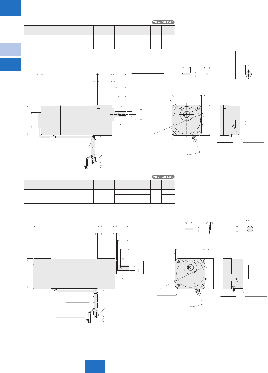
D-168
D-168 AC Speed Control Motors/DSC Series
ORIENTAL MOTOR GENERAL CATALOG
2015/2016 Page
Electromagnetic
Brake Type
Parallel Shaft
Features D-138 / System Configuration D-143 / Product Line D-157 / Specifications D-159 / Characteristics D-165
Dimensions D-166 / Connection and Operation D-171 / Motor and Driver Combinations D-170
60 W (1/12 HP)
Product Name Motor Product Name Gearhead
Product Name Gear Ratio L Mass
kg (lb.) 2D CAD
DSCI560UAM-□A -3V
DSCI560ECM-□A -3V
5IK60UGVH-UAM
5IK60UGVH-ECM 5GVH□ A
7.5∼18 45 (1.77) 5.3
(11.7)
A1411A
25∼100 58 (2.28) A1411B
120∼300 64 (2.52) A1411C
7.5
(0.30)
169 (6.65)
9
(0.35)5
(0.20)
A
A
22.5°
88 (3.46)
L
47
(1.85)
25
(0.98)
42±1
(1.65±0.04)
34
(1.34)
19.050−0.013
0
0.0000
[
0.7500−0.0005 (3/4”)
]
18±0.5
(0.71±0.02)
39−0.025
0
(
1.5354−0.0010
)
0.0000
500 (20)
15
(0.59)
90 (3.54)
5 max.
(0.20 max.)
90 (3.54)
104
±0.5
(4.09
±0.02
)
21.5
(0.85)
16.5
(0.65)
4.763−0.025
(
0.1875−0.0010
)
0
0.0000
0
4.763−0.025
(
0.1875−0.0010
)
0.0000
25±0.2
(0.984±0.008)
2.692 0
(
0.106 0.000
)
+0.381
+0.015
4.763 0
(
0.1875 0.0000
)
+0.040
+0.0016
5557-06R-210 (MOLEX)
51103-0300 (MOLEX)
Tube 11 (0.43)
4×8.5
(0.335) Thru
No.12-24 UNC
12 (0.47) Deep
Protective Earth
Terminal M4
A-AParallel Key (Included)
Detail Drawing of Protective Earth Terminal
90 W (1/8 HP)
Product Name Motor Product Name Gearhead
Product Name Gear Ratio L Mass
kg (lb.) 2D CAD
DSCI590UAM-□A -3V
DSCI590ECM-□A -3V
5IK90UGVR-UAM
5IK90UGVR-ECM 5GVR□ A
7.5∼15 45 (1.77) 5.5
(12.1)
A1412A
18∼36 58 (2.28) A1412B
50∼180 70 (2.76) A1412C
7.5
(0.30)
□90 (□3.54)
L
5
(0.20)
A
A
200 (7.87)
22.5°
42±1
(1.65±0.04)
34
(1.34)
25
(0.98)
18±0.5
(0.71±0.02)
19.050−0.013
[
0.7500−0.0005 (3/4”)
]
0
0.0000
500 (20)
15
(0.59)
39−0.025
0
(
1.5354−0.0010
)
0.0000
90 (3.54)
5 max.
(0.20 max.)
90 (3.54)
104±0.5
(4.09±0.02)
21.5
(0.85)
16.5
(0.65)
4.763−0.025
(
0.1875−0.0010
)
0
0.0000
0
4.763−0.025
(
0.1875−0.0010
)
0.0000
25±0.2
(0.984±0.008)
2.692 0
(
0.106 0.000
)
+0.381
+0.015
4.763 0
(
0.1875 0.0000
)
+0.040
+0.0016
5557-06R-210 (MOLEX)
51103-0300 (MOLEX)
Tube 11 (0.43)
4×8.5
(0.335) Thru
No.12-24 UNC
12 (0.47) Deep
Protective Earth
Terminal M4
A-AParallel Key (Included)
Detail Drawing of Protective Earth Terminal
Standard Type
Parallel Shaft/
Round Shaft
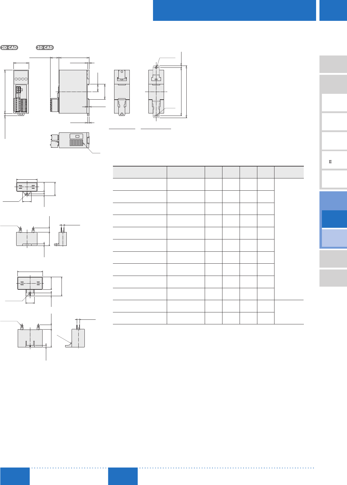
D-169
Brushless Motors/AC Speed Control Motors
D-169
Brushless
Motors
Overview,
Product
Series
AC Input
BMU
AC Input
BLE
AC Input
BLF
AC Input
BX
DC Input
BLH
DSC
BHF
AC Speed
Control
Motors
Accessories
Installation
CAD Data
Manuals www.orientalmotor.com Technical
Support TEL: (800) 468-3982
E-mail: techsupport@orientalmotor.com
Speed Controller
DSC-MU
Mass: 0.2 kg (0.44 lb.)
A1303
4 (0.16)
4 (0.16)
100 (3.94)
35
(1.38)
70 (2.76)
4 (0.16)
20 max.
(0.79 max.)
17.5
(0.69)
35.1
(1.38)
111±0.5 (4.37±0.02)
120.5 max. (4.74 max.)
R2.25
(R0.09)
(4.5)
(0.18)
(5.5) (0.22)
Slits
ϕ4.5
(ϕ0.177) Thru
DIN Installation Screw Installation
Capacitor (Included)
Dimensions No.①
ϕ4.3
(ϕ0.169)
20
(0.79)
A
C
B+10 (0.39)
B
4.5
(0.18)
4
(0.16)10
(0.39)
6 (0.24)
AMP#187
Dimensions No.②
6 (0.24)
A
CB7
(0.28)
20
(0.79)
10
(0.39)
AMP#187
ϕ4.3
(ϕ0.169)
4
(0.16)
B+15 (0.59)
R10
(R0.39)
Capacitor Dimensions Unit: mm (in.)
Product Name Capacitor
Product Name ABC
Mass
g (oz.)
Dimensions
No.
DSCI26UAM-□A -3V CH25FAUL2 31 17 27 21
①
(1.22) (0.67) (1.06) (0.74)
DSCI26ECM-□A -3V CH06BFAUL 31 14.5 23.5 18
(1.22) (0.57) (0.93) (0.64)
DSCI315UAM-□A -3V CH45FAUL2 37 18 27 26
(1.46) (0.71) (1.06) (0.92)
DSCI315ECM-□A -3V CH10BFAUL 37 18 27 27
(1.46) (0.71) (1.06) (0.95)
DSCI425UAM-□A -3V CH65CFAUL2 48 19 29 35
(1.89) (0.75) (1.14) (1.24)
DSCI425ECM-□A -3V CH15BFAUL 38 21 31 37
(1.50) (0.83) (1.22) (1.31)
DSCI540UAM-□A -3V CH90CFAUL2 48 22.5 31.5 45
(1.89) (0.89) (1.24) (1.59)
DSCI540ECM-□A -3V CH23BFAUL 48 21 31 43
(1.89) (0.83) (1.22) (1.52)
DSCI560UAM-□A -3V CH120CFAUL2 58 22 35 60
(2.28) (0.87) (1.38) (2.1)
DSCI560ECM-□A -3V CH30BFAUL 58 21 31 50
(2.28) (0.83) (1.22) (1.77)
DSCI590UAM-□A -3V CH200CFAUL2 58 29 41 91
②
(2.28) (1.14) (1.61) (3.2)
DSCI590ECM-□A -3V CH60BFAUL 58 29 41 92
(2.28) (1.14) (1.61) (3.2)
A capacitor cap is included with the capacitor.
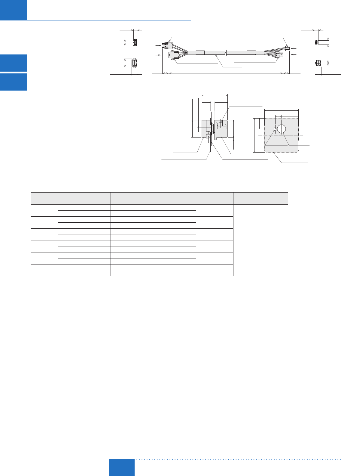
D-170
D-170 AC Speed Control Motors/DSC Series
ORIENTAL MOTOR GENERAL CATALOG
2015/2016 Page
Standard Type
Parallel Shaft/
Round Shaft
Electromagnetic
Brake Type
Parallel Shaft
Features D-138 / System Configuration D-143 / Product Line D-157 / Specifications D-159 / Characteristics D-165
Dimensions D-166 / Connection and Operation D-171 / Motor and Driver Combinations D-170
■List of Motor and Speed Controller Combinations
Output Power Product Name Combination Type Motor
Product Name✽
Motor
Product Name
Gearhead
Product Name
Speed Controller
Product Name
6 W
(1/125 HP)
DSCI26UAM-□ A-3V 2IK6UUAM-□A 2IK6UGV-UAM 2GV□A
DSC-MU
DSCI26ECM-□ A-3V 2IK6UECM-□A 2IK6UGV-ECM
15 W
(1/50 HP)
DSCI315UAM-□ A-3V 3IK15UUAM-□A 3IK15UGV-UAM 3GV□A
DSCI315ECM-□ A-3V 3IK15UECM-□A 3IK15UGV-ECM
25 W
(1/30 HP)
DSCI425UAM-□ A-3V 4IK25UUAM-□A 4IK25UGV-UAM 4GV□A
DSCI425ECM-□ A-3V 4IK25UECM-□A 4IK25UGV-ECM
40 W
(1/19 HP)
DSCI540UAM-□ A-3V 5IK40UUAM-□A 5IK40UGV-UAM 5GV□A
DSCI540ECM-□ A-3V 5IK40UECM-□A 5IK40UGV-ECM
60 W
(1/12 HP)
DSCI560UAM-□ A-3V 5IK60UUAM-□A 5IK60UGVH-UAM 5GVH□A
DSCI560ECM-□ A-3V 5IK60UECM-□A 5IK60UGVH-ECM
90 W
(1/8 HP)
DSCI590UAM-□ A-3V 5IK90UUAM-□A5IK90UGVR-UAM 5GVR□A
DSCI590ECM-□ A-3V 5IK90UECM-□A 5IK90UGVR-ECM
✽Combination type motor product names are names of special order products in which motors and gearheads are pre-assembled.
A number indicating the gear ratio is entered where the box □ is located within the product name.
Connection Cable (Included)
13.8
(0.54)
9.7
(0.38)
7.5
(0.30)
7.8
(0.31)
(12) (0.47)
(0.91)
16.7
(0.66)
15
(0.59)
15
(0.59)
3000 (9.8 ft.)
9 (0.35)
(15) (0.59)
A
B
C
D
A
B
C
D
(23)
5559-06P-210 (MOLEX)5557-06R-210 (MOLEX)
51103-0300 (MOLEX)
51198-0300 (MOLEX)
Motor Side Speed Controller Side
External Speed Potentiometer (Included)
9.5
(0.37)
ϕ2.8 (ϕ0.11)
15
(0.59)
3
(0.12)
Knob
Dial Plate
□40 (□1.57) t=0.5 (0.02)
Insulated Sheet
□40 (□1.57) t=0.5 (0.02)
Potentiometer
40 (1.57)
7.5 (0.30)
12.5
(0.49)
40 (1.57)
Insulated Sheet
ϕ30.2
(ϕ
0.1180.008
)
ϕ9.50.2
(
ϕ0.3740.008
)
30 (1.18) min.
ϕ20 (ϕ0.79)
ϕ20
(ϕ0.79)
M4×6 (0.24) Deep
(Screw)
Recommended thickness of a mounting plate is a maximum of 4.5 mm (0.18 in.).
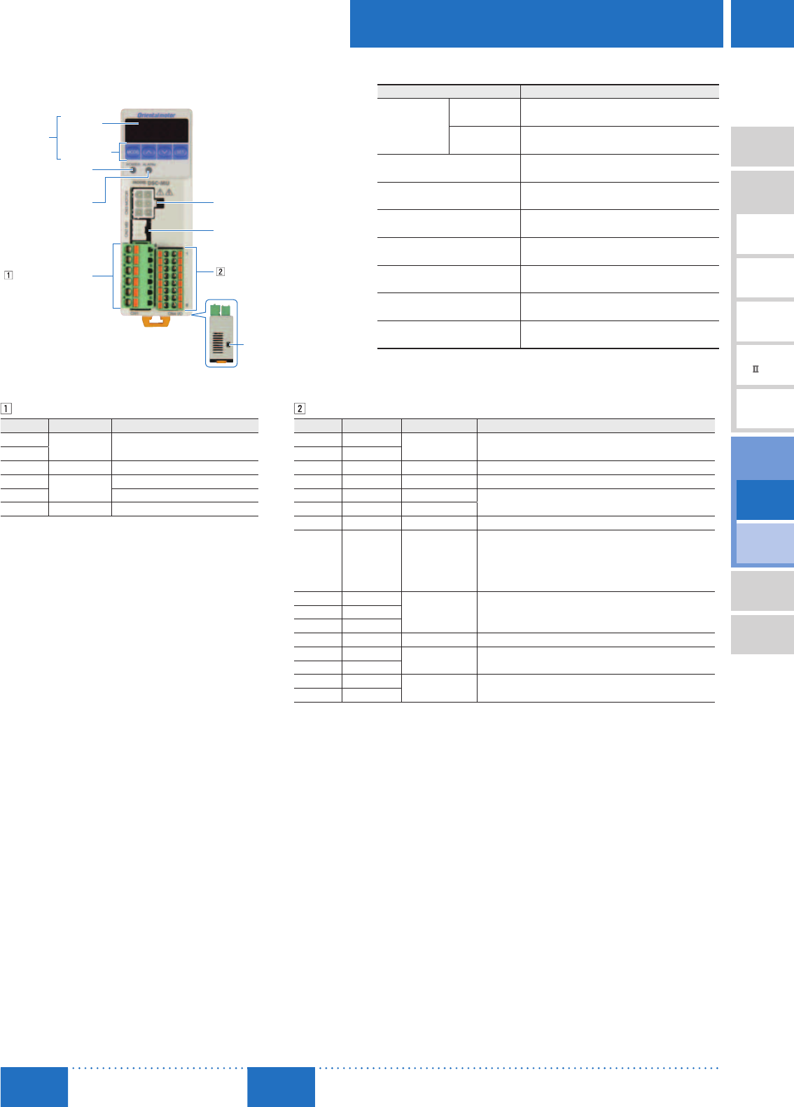
D-171
Brushless Motors/AC Speed Control Motors
D-171
Brushless
Motors
Overview,
Product
Series
AC Input
BMU
AC Input
BLE
AC Input
BLF
AC Input
BX
DC Input
BLH
DSC
BHF
AC Speed
Control
Motors
Accessories
Installation
CAD Data
Manuals www.orientalmotor.com Technical
Support TEL: (800) 468-3982
E-mail: techsupport@orientalmotor.com
■Connection and Operation
Names and Functions of Speed Controller Parts
Control Panel
Indicator
Operation Key
ALARM LED
(Red)
Main Circuit Connector
(CN1)
Motor Connector
(CN3)
Electromagnetic Brake Connector
(CN2)✽
Control Circuit Connector
(CN4)
POWER LED
(Green)
Sink Logic/
Source Logic
Switch (SW1)
Name Overview
Control Panel
Indicator
(4 digit LED) Displays speed, parameters, alarms, etc.
Operation Key Switches operating mode, sets operating data and
changes parameters.
POWER LED
(Green)
Lights when the AC power supply is provided to the
speed controller.
ALARM LED
(Red) Lights when an alarm is activated.
Motor Connector
(CN3) Connects to the motor connector.
Electromagnetic Brake Connector
(CN2)✽Connects to the electromagnetic brake connector.
Main Circuit Connector
(CN1) Connects to the AC power supply, capacitor and FG.
Control Circuit Connector
(CN4)
Connects the DC power supply for control and I/O
signals.
Sink Logic/Source Logic Switch Switches between the sink logic and source logic
for the input signal.
✽Only the electromagnetic brake type is connected.
Main Circuit Connector (CN1)
Pin No. Contents Description
1Capacitor Connects the capacitor.
2
3 N.C. No connection.
4AC Power
Supply
Connects to the live side.
5 Connects to the neutral side.
6 FG Connects to the ground wire.
Control Circuit Connector (CN4)
Pin No. Signal Name Function✽1Description
1+24 V DC Power Supply
for Control Connects the 24 VDC power supply for control circuit.
2 0 V (GND)
3 IN0 [FWD] The motor rotates in the forward direction when "ON." ✽2
4 IN1 [REV] The motor rotates in the reverse direction when "ON." ✽2
5 IN2 [M0] Selects the operating data.
6 IN3 [M1]
7 IN4 [ALARM-RESET] Alarms are canceled.
8 IN5 [FREE]
When the FREE input is set to "ON" during motor operation,
the motor will perform a coasting stop. When the FREE input is
"ON", the motor will not rotate, even if the FWD input or REV
input are set to "ON". For electromagnetic brake type, when
the FREE input is "ON", the electromagnetic brake is released.
9VH
External Speed
Setting Input
It is connected when speed is set externally using external
speed potentiometer or external DC voltage.
10 VM
11 VL
12 N.C. −No connection.
13 OUT0+[SPEED-OUT] 12 pulses are output when the motor output shaft makes one
rotation.
14 OUT0−
15 OUT1+[ALARM-OUT] Output when an alarm activates. (Normally closed)
16 OUT1−
✽1 Text inside the [ ] represents the factory default function assignment. The following signals can be assigned as
necessary to 6 input signal terminals (IN0∼IN5) and 2 output signal terminals (OUT0, OUT1).
6 of the 7 input signals (FWD, REV, M0, M1, ALARM-RESET, FREE, EXT-ERROR)
2 of the 4 output signals (SPEED-OUT, ALARM-OUT, TH-OUT, WNG)
✽2 Rotation direction varies according to the gearhead's gear ratio and the parameter settings.
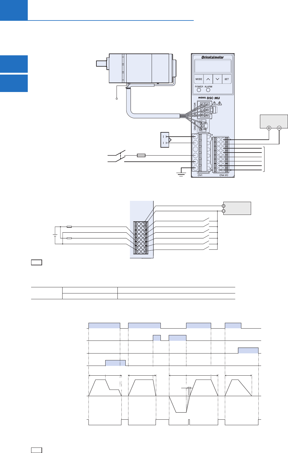
D-172
D-172 AC Speed Control Motors/DSC Series
ORIENTAL MOTOR GENERAL CATALOG
2015/2016
Standard Type
Parallel Shaft/
Round Shaft
Electromagnetic
Brake Type
Parallel Shaft
Connection Diagram
The figure shows a connection example for the electromagnetic brake type. Always connect the DC power supply for control when operating the
motor in addition to the AC power supply.
24 VDC±10%
150 mA min.
L (Live)
N (Neutral)
FG
Capacitor
Speed Controller
AC Power Supply
Fuse
Single-Phase 110/115 VAC 60 Hz
Single-Phase 220/230 VAC 50/60 Hz
PE
Motor
Input Signal
Connect to CN4
DC Power Supply for Control✽
✽Use a power supply with reinforced insulation on the primary and secondary sides for the DC power supply for control.
Example of I/O Signal (CN4) Connection
The figure shows a connection example when operating with a contact switch, such as switches and relays with sink logic setting.
Pin No. 2 0 VDC (GND)
Pin No. 1 +24 V
Pin No. 3 IN0 [FWD]
Pin No. 4 IN1 [REV]
Pin No. 5 IN2 [M0]
Pin No. 6 IN3 [M1]
Pin No. 7 IN4 [ALARM-RESET]
Pin No. 8 IN5 [FREE]
24 VDC±10%
150 mA min.
R0✽
R0✽
Pin No. 13 OUT0+ [SPEED-OUT]
Pin No. 14 OUT0− [SPEED-OUT]
Pin No. 15 OUT1+ [ALARM-OUT]
Pin No. 16 OUT1− [ALARM-OUT]
4.5∼30 VDC
40 mA max.
✽Recommend Resistance Value
24 VDC: 680
∼4.7 k
(2 W) 5 VDC: 150
∼1 k
(0.5 W)
Note
Connect a limiting resistor R0 that corresponds to the power supply used, so that the current that flows with the output signals does not exceed 40 mA.
Rating of Fuse
For overcurrent protection, be sure to insert a fuse into the power supply line.
Rating of Fuse Single-Phase 110/115 VAC 216 Series (Littelfuse, Inc.) 10 A or equivalent
Single-Phase 220/230 VAC 216 Series (Littelfuse, Inc.) 6.3 A or equivalent
After setting the speed, when the
FWD or REV input is set to ON, the
motor is rotated at the set speed.
During motor operation, when the
signal that is ON (either FWD or
REV input) is turned OFF, the motor
will perform a deceleration stop
within the set deceleration time .
If the FWD input and REV input
are turned ON simultaneously, the
motor will stop instantaneously.
For electromagnetic brake types,
the motor stops and the brake is
simultaneously activated.
Timing Chart
Operating data No.0 has been set to 1200 r/min and operating data No.1 has been set to 300 r/min.
ON
OFF
ON
OFF
ON
OFF
REV Input
ON
OFF
FREE Input
FWD Input
M0 Input
Illustration of Operation
FWD Direction
REV Direction
300 r/min
1200 r/min
Run/Speed-Select/
Stop
Run/
Instantaneous Stop
Instantaneous Bi-Directional
Operation
Operate/
Coasting Stop
Hold
Release
Electromagnetic Brake✽1✽2
✽2
✽1 Only for electromagnetic brake type.
✽2 Only for electromagnetic brake type. Holds while "deceleration control" parameter is ON, and time lag occurs during motor standstill (approx.
0.1seconds). Does not hold when "deceleration control" parameter is OFF. There is no time lag, either.
Note
The duration of ON for each signal must be 10 ms or more.
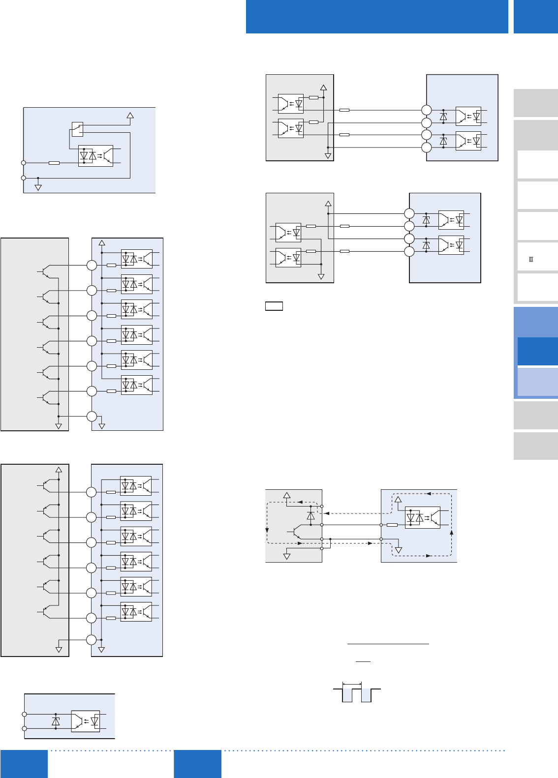
D-173
Brushless Motors/AC Speed Control Motors
D-173
Brushless
Motors
Overview,
Product
Series
AC Input
BMU
AC Input
BLE
AC Input
BLF
AC Input
BX
DC Input
BLH
DSC
BHF
AC Speed
Control
Motors
Accessories
Installation
CAD Data
Manuals www.orientalmotor.com Technical
Support TEL: (800) 468-3982
E-mail: techsupport@orientalmotor.com
I/O Signal Circuits
Sink logic or source logic can be selected according to the external
control device the customer is using.
Input Circuit
IN0∼IN5
0 V
+24 V
CN4
Pin No.
3∼8
2
4.7 k
SW1 SINK
SOURCE
Connection to Programmable Controller
Sink Logic
3
4
5
6
IN0
IN1
IN2
IN3
Programmable Controller Speed Controller
+24 V
CN4
4.7 k
4.7 k
4.7 k
4.7 k
7
IN4 4.7 kΩ
8
2
IN5 4.7 kΩ
0 V 0 V
Source Logic
3
4
5
6
IN0
IN1
IN2
IN3
Programmable Controller
+24 V
Speed Controller
CN4
4.7 k
4.7 kΩ
4.7 kΩ
4.7 kΩ
7
IN4 4.7 kΩ
8
IN5 4.7 kΩ
2
0 V0 V
Output Circuit
OUT0, OUT1
14, 16
13, 15
CN4
Pin No.
Connection to Programmable Controller
Sink Logic
CN4
Programmable Controller Speed Controller
OUT0+
OUT0−
OUT1+
OUT1−
13
14
15
16
40 mA max.→
40 mA max.→
0 V
R0✽
R0✽
4.5∼30 VDC
max.
Source Logic
CN4
Programmable Controller Speed Controller
15
16
40 mA max.→
0 V
R0✽
14
13
40 mA max.→
4.5∼30 VDC
max.
R0✽
OUT0+
OUT0−
OUT1+
OUT1−
✽Recommended Resistance Value
24 VDC: 680
∼4.7 k
(2 W) 5 VDC: 150
∼1 k
(0.5 W)
Note
Maintain the current value of OUT0 and OUT1 at 40 mA or less. If this current value is exceeded,
connect the limiting resistor R0.
When an External Control Device with a Built-in Clamp Diode
is Used
If an external control device with a built-in clamp diode is connected
and the external control device is turned off when the speed
controller power is on, current may flow in and rotate the motor.
Also, depending on the external control device used with the speed
controller, the motor may rotate even when the power supply is set
to ON and OFF simultaneously. Use the following procedure to turn
the power ON or OFF.
When turning the power off:
Speed controller ➜ External control device
When turning the power on:
External control device ➜ Speed controller
External Control Device Speed Controller
VCC +24 V
0 V
0 V
Clamp Diode
CN4
Pin No. 3∼8
Pin No. 2
Speed Output (SPEED-OUT)
Pulse signals of 12 pulses are output at every rotation of the motor
output shaft in synchronization with the motor operation.
If the speed output frequency is measured, the motor speed can be
calculated.
Motor Shaft Speed [r/min]= × 60
Speed Output Frequency [Hz]
12
Speed Output Frequency [Hz]=1
T [s]
T [s]
Speed Output Waveform
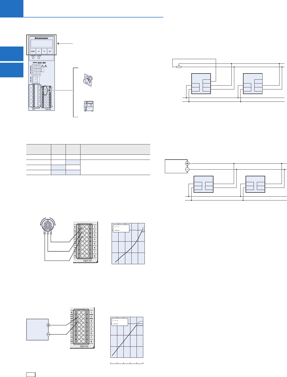
D-174
D-174 AC Speed Control Motors/DSC Series
ORIENTAL MOTOR GENERAL CATALOG
2015/2016
Standard Type
Parallel Shaft/
Round Shaft
Electromagnetic
Brake Type
Parallel Shaft
Speed Setting Method
The following 3 methods for setting speed can be used.
(2) External speed potentiometer
Included
(3) External DC voltage
0∼5 VDC or 0∼10 VDC
(1) Setting by control panel (factory setting)
Remote Setting
Setting by Control Panel
Up to 4 operating data can be set.
By switching the M0 and M1 inputs between ON and OFF, the
pattern can be selected and the motor will operate.
Operating Data
No. M1 M0 Contents
0 OFF OFF Setting by control panel/remote setting✽
1 OFF ON
Setting by control panel2 ON OFF
3ONON
✽When the "External speed command input" parameter is set to "ON (enabled)" (Initial value: OFF),
the speed can be set using the external speed potentiometer and external DC voltage.
Setting by External Speed Potentiometer (Included)
Connect the external speed potentiometer to CN4.
"External speed command voltage selection" parameter setting:
"0-5" (Initial value)
Pin No. 10
VM Input
Pin No. 9
VH Input
Pin No. 11
VL Input
High SpeedLow Speed
123
External Speed Potentiometer
0 20406080100
Potentiometer Scale
External Speed Potentiometer –
Speed Characteristics (Representative values)
500
1000
1500
1800
Motor Shaft Speed [r/min]
60 Hz
50 Hz
Setting by External DC Voltage
Connect the external DC power supply (0∼5 VDC or 0∼10 VDC) to CN4.
"External speed command voltage selection" parameter setting:
0∼5 VDC "0-5" (Initial value)
0∼10 VDC "0-10"
0∼5 VDC
or
0∼10 VDC
1 mA min.
External
DC Power Supply
Pin No. 11
VL Input
Pin No. 10
VM Input
External DC Voltage –
Speed Characteristics (Representative values)
500
1000
1500
1800
Motor Shaft Speed [r/min]
0246810
DC Voltage [VDC]
012345
60 Hz
50 Hz
Note
Ensure that the external DC voltage is 10 VDC or less. When connecting the external DC voltage,
ensure that the polarity is correct. Otherwise, it may damage the speed controller.
Parallel-Motor Control
Multiple motors can be operated at the same speed using 1 external
speed potentiometer or external DC voltage.
Using an External Speed Potentiometer
Parallel-motor operation using the external speed potentiometer
(VRx) should be performed with a maximum of 20 speed controllers.
31
2
VRx
Control Line
Controller 1 Controller n
VM
VL
L
N
VH
CN1
CN4
VM
VL
L
N
VH
CN1
CN4
AC Power
Supply Line
Speed Controller
The Calculation Method of the Resistance Value (VRx) when the
Number of Speed Controllers Connected is n
Resistance value (VRx) = 20/n (k
), permissible loss=n/4 (W)
Example: When connecting 2 speed controllers
Resistance value = 20/2 = 10 (k
), permissible loss = 2/4 = 1/2 (W)
Using External DC Voltage
The number of connected units will be limited depending on the
current capacity of the external DC power supply.
0∼5 VDC
or
0∼10 VDC
DC Power Supply
Control Line
Controller 1 Controller n
VM
VL
L
N
CN1 CN4
VM
VL
L
N
CN1 CN4
AC Power
Supply Line
Speed Controller
The Calculation Method of the Current Capacity of the External
DC Power Supply (I) when the Number of Speed Controllers
Connected is n
Current capacity (I)=1×n (mA)
Example: When connecting 2 speed controllers
Current capacity (I)=1×2=2 (mA)

D-175
Brushless Motors/AC Speed Control Motors
D-175
Brushless
Motors
Overview,
Product
Series
AC Input
BMU
AC Input
BLE
AC Input
BLF
AC Input
BX
DC Input
BLH
DSC
BHF
AC Speed
Control
Motors
Accessories
Installation
CAD Data
Manuals www.orientalmotor.com Technical
Support TEL: (800) 468-3982
E-mail: techsupport@orientalmotor.com
Repetitive Operation Cycle
When the motor is operated repeatedly in short cycles, use the
cycles below as a reference, and ensure that the motor's external
temperature is at 90˚C (194˚F) or less.
Instantaneous
Stop
6∼40 W
(1/125∼1/19 HP)
When operation and instantaneous stops are repeated
2 seconds min., operating duty 50% max.
(Example: 1 second operating, 1 second stopped)
60 W, 90 W
(1/12 HP, 1/8 HP)
When operation and instantaneous stops are repeated
4 seconds min., operating duty 50% max.
(Example: 2 seconds operating, 2 seconds stopped)
Instantaneous
Bi-Directional
Operation
6∼40 W
(1/125∼1/19 HP)
When rotation direction is repeatedly switched during operation
Switch once every 2 seconds min.
60 W, 90 W
(1/12 HP, 1/8 HP)
When rotation direction is repeatedly switched during operation
Switch once every 4 seconds min.
On the electromagnetic brake type, continuous operation conditions occur when the "deceleration
control" parameter is set to ON. Check the electromagnetic brake type "Common Specifications -
Permissible Continuous Operation Time While Deceleration Control is ON" ( ➜ Page D-159)
Brake Current
When performing an instantaneous stop, bi-directional operation or
vertical operation✽, the large brake current flows for approximately
0.4 seconds on a half-wave rectified AC power supply line.
When performing these kinds of operations, select the equipment
breaker and AC power supply capacitance by referring to the table's
braking current (peak value).
Motor Output Power Braking Current (Peak value)
Single-Phase 110/115 VAC Single-Phase 220/230 VAC
6 W (1/125 HP) 2 A 1 A
15 W (1/50 HP) 4 A 3 A
25 W (1/30 HP) 8 A 4 A
40 W (1/19 HP) 12 A 7 A
60 W (1/12 HP) 21 A 10 A
90 W (1/8 HP) 29 A 13 A
✽Only for electromagnetic brake type.
