Flow Pisco 2 Stage Speed Control 1505490155 Bjsu1 User Manual
Pisco 2 Stage Speed Control-1505490155 PISCO_2_STAGE_SPEED_CONTROL-1505490155 PISCO_2_STAGE_SPEED_CONTROL-1505490155 PISCO 2 STAGE SPEED CONTROL Fittings & Flow Controls s production assets-flotronics
2017-10-06
User Manual: Flow Pisco 2 Stage Speed Control-1505490155
Open the PDF directly: View PDF ![]() .
.
Page Count: 4
S
m a r t
P
roduct
CUSHION
No, NP 49-03e
Be bothered by installation or replacement of a shock absorber?
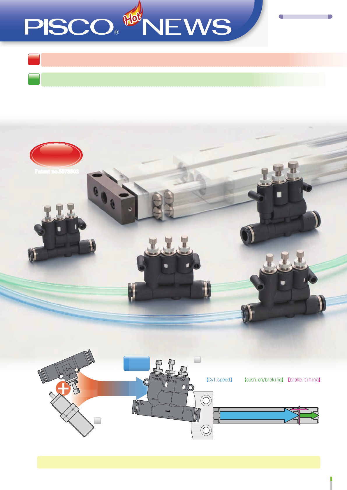
There is a solution with Pisco's
2-stage Speed Controller
Q
A
2 in
1
Speed controller
Shock Absorber
Patent no.5578502
Industry's
First
Product's initial series name "Brake built-in Speed Controller" has been changed to "2-stage Speed Controller", which describes its
feature more appropriately.
Durability
is
about
3 times
of
a normal cylinder mounting type shock absorber.
By 3 needles,
Initial speed
&
2nd speed
&
Shift timing
are adjusted separately.
1

250
200
150
100
50
Stroke(mm)
03210 4 5 6
TIME (S)
2-stage Speed Controller
Standard speed controller
Speed 200
(
EX1(SPEED)
)
Shortended cycle time
sec
Cycle time Chart
1.61.6
Speed100
Speed100(EX2(CUSHION))
➡
➡
1.2 sec
200mm(Stroke)
2-stage Speed Controller
Conventional Standard Speed Controller Shock absorber
EX1(SPEED)(Initial speed : 200mm/sec)
EX2(CUSHION)(2nd Speed : 100mm/sec)
TIM( )TIM( )
Shock absorber
250
200
150
100
50
Stroke(mm)
Shock (m/s²)
0
0
5
10
15
20
3210 4 5 6
TIME (S)
2-stage Speed Controller
Standard speed controller
Speed 30(EX2(CUSHION))
Speed 200(EX1(SPEED))
Shock of standard speed controller
Shock of 2-stage Speed Controller
Speed100
Shock absorbing effect chart
➡
➡
2 sec
200mm(Stroke)
2-stage Speed Controller
Conventional Standard Speed Controller Shock absorber
EX1(SPEED)(Initial speed : 200mm/sec)
EX2(CUSHION)(2nd speed : 30mm/sec)
TIM(TIMER)
Speed : 100mm/sec
2-stage Speed Controller
Shock absorber is not required.
It is possible to shorten traveling (cycle) time as long as
conventional shock absorbing (cushion) property is same.*
*Conventional shock absorbing property means shock absorbing by reducing the cylinder speed by a cylinder mounting type
shock-absorber near the stroke end.
e.g. Actuate 80% of cylinder stroke at the speed of twice as fast as the regular speed of a conventional standard speed
controller,
then actuate the last 20% of the stroke at the regular speed.
Adjustment of shock absorbing property is possible by
the adjustment of 2nd speed (EX2 (CUSHION
2-stage speeds can be controlled by individual needles.
e.g. Reducing the shock to 1/9 (reducing speed to 1/3) while keeping the same cycle time.
Speed shift timing is adjustable.
The speed shifting (brake) timing from EX1 to EX2 can be set at the position where the shock absorber does not work.
Intermediate stop of cylinder is possible.
Feature
2
TIMER
IN
OUT
TIM (TIMER)
EX2 (CUSHION)
EX1 (SPEED)
①
④
⑤
⑥
⑦ ⑧ ⑨ ⑩ ⑪ ⑫ ⑬ ⑭
⑮
⑯
⑰
⑱
⑲
⑳
②③
160
180
200
140
120
100
80
60
40
20
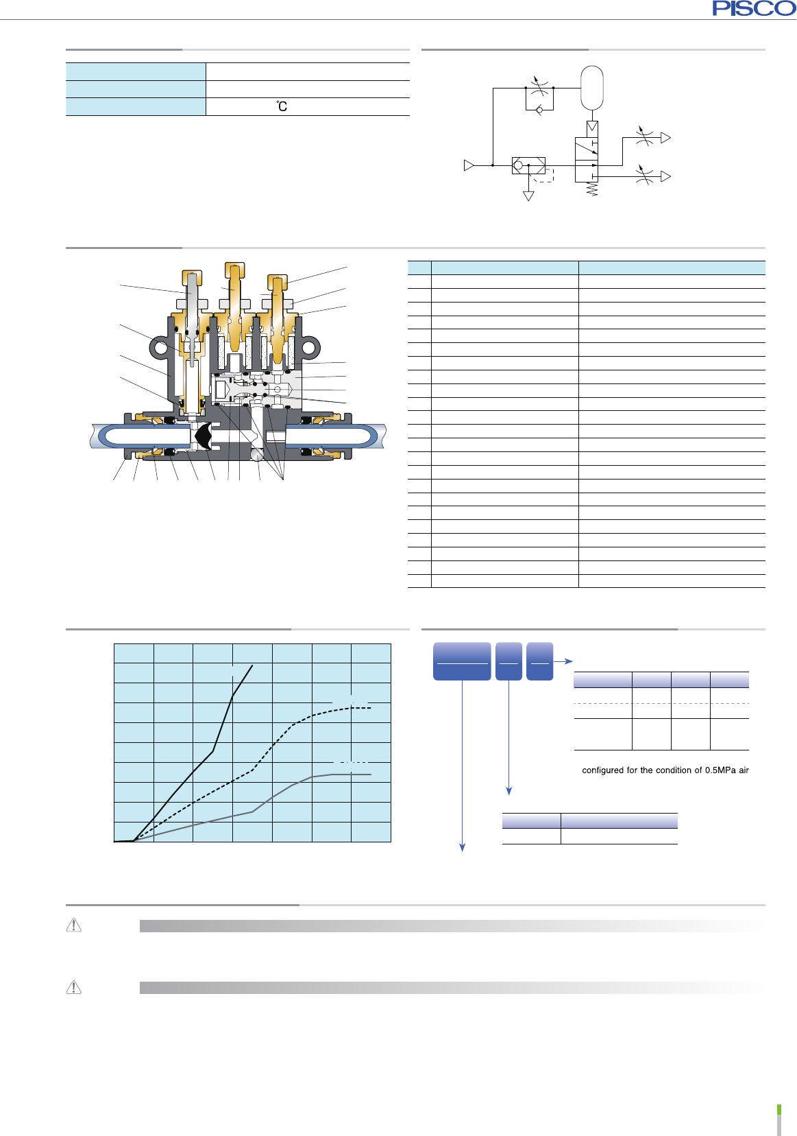
Exhaust flow(ℓ/min[ANR])
06420 8 10 12 14
Number of needle rotation
BJSU6
BJSU4
BJSU8
BJSU6
BJSU4
BJSU8
Specification Pneumatic Symbol
Fluid medium Air
Operating pressure range
0.2~1.0MPa
Operating temp. range 0~60 (No freezing)
Construction
Exhaust flow characteristic
(Air supply :0.5MPa) Model Designation (Example)
BJS
①
U
②
4
③
②.Type
Code
U
Type Union Straight
③.Tube dia.
Code
468
Metric(㎜)
Inch
ø4
ø5/32
ø6 ø8
ø5/16
Applicable max.
)㎜( erob rednilyc
ø20 ø25
‐
ø32
※The above max. cylinder bore sizes are
supply and cylinder speed of 500mm/sec.
①.
2-stage Speed Controller
Detailed Safety Instruction
Warning
Cautions
Adjust a speed of an actuator by referring to Speed adjusting method(Page.4).
Inappropriate procedure may result in rapid action or jumping out of an actuator under incorrect procedure.
1. Since the speed controllers is designed to tolerate some leakage, avoid using on an application requiring complete air-tightness.
2. During braking ( shock absorbing ) process, thrust of a cylinder is reduced by back pressure till the residual air in cylinder is
exhausted completely.
3. Air leak around a cylinder may affect the speed adjustment.
4. Do not block the exhaust ports during the adjustment and operation.
http://www.pisco.co.jp/
3
No. Part Material
①Timer (TIM) needle Special stainless steel
②Speed (EX1) needle Electroless nickel-plated brass
Electroless nickel-plated brass
③Cushion(EX2) needle
④Inner ring Electroless nickel-plated brass
⑤Resin body PBT
⑥Diaphragm HNBR
⑦Release-ring POM
⑧Guide-ring Electroless nickel-plated brass
⑨Lock-claws Stainless steel
⑩Elastic-sleeve NBR
⑪Valve retainer Aluminum
⑫Valve element HNBR
⑬Spring Stainless steel
⑭Stopper ball Stainless steel
⑮Main spool O-ring HNBR
⑯Main valve spool Aluminum
⑰Main spool guide Aluminum
⑱Silencer PVF
⑲Needle guide Electroless nickel-plated brass
⑳Lock nut Aluminum
Knob Electroless nickel-plated brass
Spool seal packing HNBR: BJSU4, NBR: BJSU6 & BJSU8
Fixed O-ring NBR

B3
F1 2-ø3.3
F2
CøP1
F3 T
øD
B1
B2
øP2 2-øP3
CUSHION
BJSU
Ⓑ
EX1(SPEED)
needle
Adjust the operating (initial)
speed of drive equipment.
Ⓐ
TIM(TIMER)needle
Adjust the speed shift timing.
quick fast slow slow fast
ⒸEX2(CUSHION)needle
Adjust the 2nd (braking) speed
for controlling intensity of a brake
or shock absorbing property.
late
CUSHION
SP
SP
SE
SE CUSHION
CUSHION
ⒸEX2
(CUSHION)
ⒸEX2
(CUSHION)
ⒶTIM
(TIMER)
ⒶTIM
(TIMER)
Advancing
Retracting
ⒷEX1
(SPEED)
ⒷEX1
(SPEED)
Stroke EndStarting position
2-stage Speed Controller
Speed adjusting method
Outline Dimensional Drawing
Union Straight
Unit:mm
Model
Tube O.D.
øD
B1 B2 B3 øP1 øP2 øP3
Tube end
CF1 F2 F3 T Eff. sect Area
(㎟) WT.
(g)
Price
(¥)max. min. max. min.
IN→OUT
OUT →EX1 OUT →EX2
BJSU4 4 38.3 35.7 37.1 34.4 51.1 10 10 10 14.9 32 9.2 18.9 10.4 2.6 1.0 1.0 21 4,500
BJSU6 6 45.7 42 44.7 40.8 58.5 12.5 12.5 12.5 17 38 9.5 22.7 13 4.5 2.0 2.0 33 4,700
BJSU8 8 52.5 48.8 52 49 65.6 14.5 12.5 14.5 18.1 43 11.1 29.5 15 5.0 2.6 2.6 52 4,900
■
Function of each needle
■
Controlling details
■
Speed adjusting method
Tips for the adjustment
① Install the product. Connect tube from cylinder port to the OUT side of the product.
②Before carrying out the speed adjustment, fully open TIM and EX1 needles by turning them couterclockwise and completely close
EX2 needle by turning it clockwise.
③Adjust the 2nd (braking) speed with EX2 needle. Actuate the cylinder by gradually opening the EX2 needle so that the piston moves and
reaches to stroke-end. Tighten the lock nut while holding the needle head in order not to change the adjusted speed.
④Adjust the shift (brake) timing with TIM needle. Close TIM needle gradually so that the break (shock absorber function) works near the
stroke end. Do not turn the TIM needle to near full close position or close the needle quickly from full open positon, otherwise speed shifting
effect (brake or shock absorbing function) does not work.
⑤When decelerate the operating speed of the cylinder, adjust EX1 needle and readjust the timing of speed shift (brake) again.
⑥ needle heads of TIM and EX1 in order not to change
the adjusted setting.
・Fix the pressure and the length of tube before adjusting these needles, so that the setting of this product will not be affected.
・As for speed adjusting process①~③, adjust two controlles together at the both sides of the cylinder, then adjust them separately
for process ④~⑥.
・Completely open EX1 needle (accelerate cylinder) and nearly completely close EX2 needle (strengthen a brake), when the timing of
・
・Adjust all needles over again if encountering a problem.
Cylinder side
Cylinder side
Solenoid Valve side
Solenoid Valve side
Knob Lock nut
●2014.11-2 PDF
4
463 W WRIGHTWOOD AVE.
ELMHURST IL 60126 USA
TEL: +1-630-993-3500 FAX: +1-630-993-3501
www.pisco.com Email: inquiry@pisco.com
3,6&286$,1&
