Fluke Electronics DMFBLE Test & Measurement products User Manual 0master
Fluke Electronics Test & Measurement products 0master
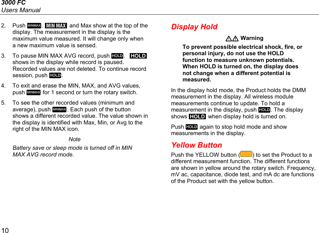
UserManual.wiki
>
Fluke Electronics
>
DMFBLE User Manual
>
User Manual
Contents
1.
User Manual
2.
RF warning Statements
User Manual
Navigation menu
Upload a User Manual
Namespaces
Wiki Guide
HTML
PDF
Info
Views
User Manual
Discussion / Help
Navigation
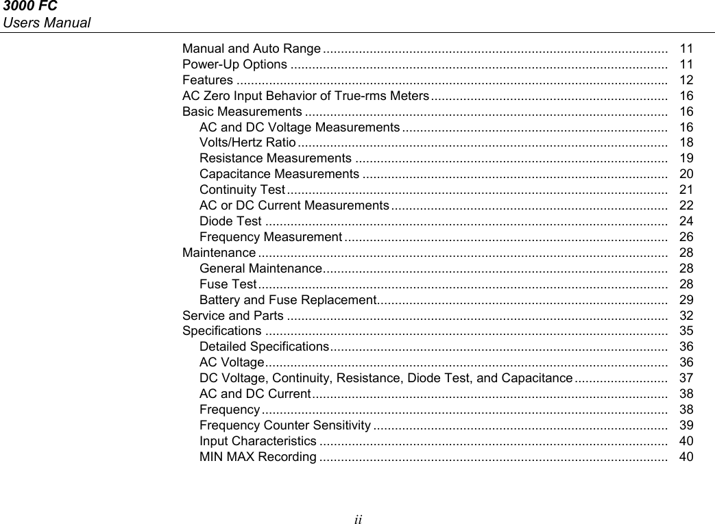


![Wireless Multimeter Features 13 Table 4. Rotary Switch Positions Switch Position Function DC voltage from 1 mV to 1000 V. Push to measure frequency from 2 Hz to 99.99 kHz AC voltage measurement from 60.0 mV to 1000 V. Push to measure frequency from 2 Hz to 99.99 kHz. Push again to measure Volts/Hertz. DC voltage measurements from 1 mV to 600 mV. Push to measure ac voltage from 6 mV to 600 mV. [1] Resistance measurements from 0.1 Ω to 50 MΩ. Push to measure capacitance from 1 nF to 9999 μF. Continuity. Beeper turns on at <25 Ω and turns off at >250 Ω. Push for diode test. Shows OL above 2.0 V. AC current measurements from 3.00 mA to 400 mA. Push to measure dc current from 3.00 mA to 400 mA. [1] Push again to measure frequency from 2 Hz to 9.99 kHz. [1] This function will stay in ac or dc when the function switch is moved to another position and back to this function. Even when turned to off and back to this function.](https://usermanual.wiki/Fluke-Electronics/DMFBLE.User-Manual/User-Guide-2240576-Page-21.png)
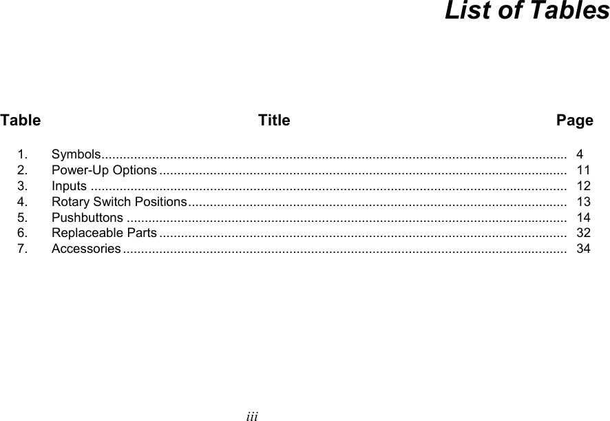
![3000 FC Users Manual 14 Table 5. Pushbuttons Button Switch Position Function Selects frequency. Selects frequency. Selects ac millivolts. [1] Selects capacitance. Selects diode test. Push once to select dc milliamps. Push twice to select ac frequency. [1] All positions Sets the Product to manual range and scrolls through each range. Push for 1 second to set the Product to autorange. All positions Freezes the display](https://usermanual.wiki/Fluke-Electronics/DMFBLE.User-Manual/User-Guide-2240576-Page-22.png)
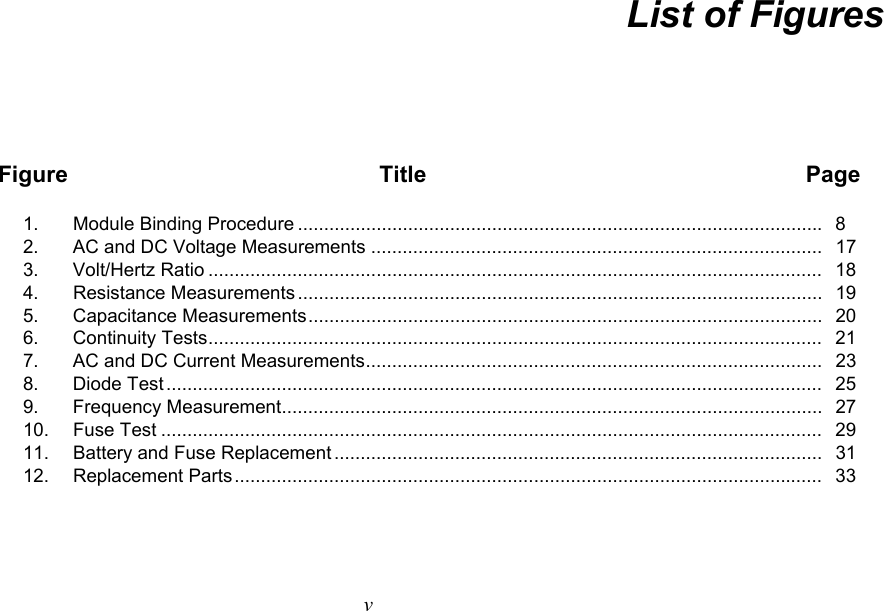
![Wireless Multimeter Features 15 Table 5. Pushbuttons (cont.) Button Switch Position Function Not related to switch position Push once to turn on the backlight and push again to turn off the backlight. The backlight turns off automatically after 2 minutes. All positions Starts the MIN MAX record function. Steps the display through MAX, MIN, AVG (average), and input signal measurement. Push for 1 second to stop MIN MAX record. Not related to switch position Selects/deselects the highlighted wireless module in the display. Hold for 1 second to bind all selected modules to the Product and stop the discovery procedure. [2] Not related to switch position Moves the highlight in the display to the next wireless module shown in the display. [2] Not related to switch position Turns on the radio and starts the module discovery procedure. shows in the display when the radio is on. Turns off the radio when the radio is on.[2] [1] This function will stay in ac or dc when the function switch is moved to another position and back to this function. Even when turned to off and back to this function. [2] This button is used when the Product connects with a wireless module. See the “Discovery of Modules” section to learn more.](https://usermanual.wiki/Fluke-Electronics/DMFBLE.User-Manual/User-Guide-2240576-Page-23.png)
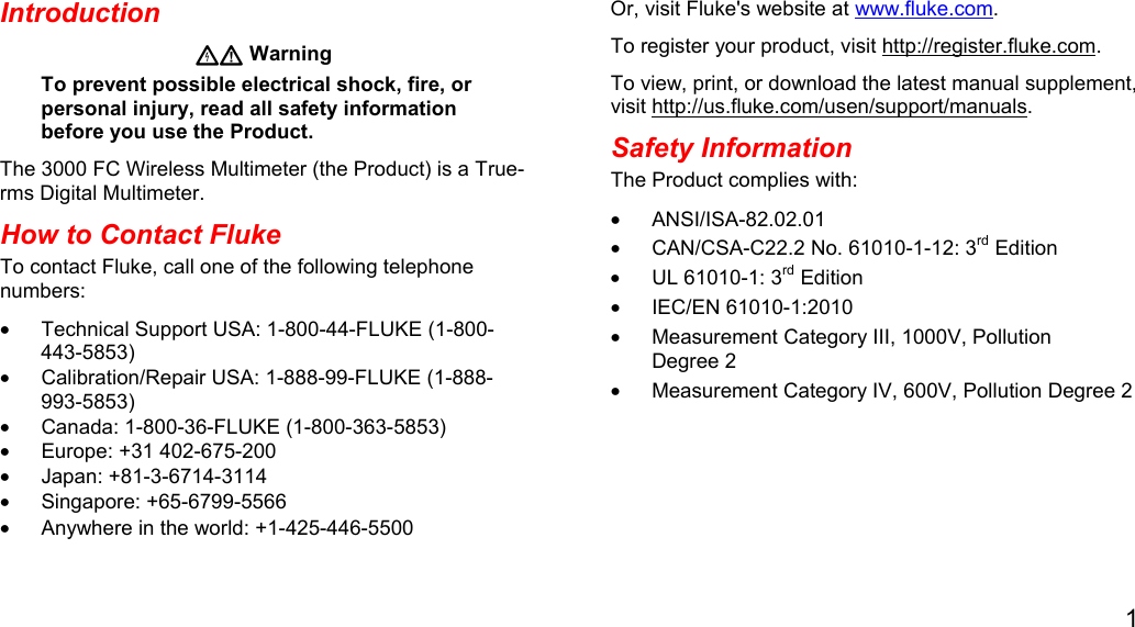
![3000 FC Users Manual 36 Safety ..................................................................... IEC 61010-1: 600 V CAT IV / 1000 V CAT III, Pollution Degree 2 EM Environment ................................................. IEC 61236-1: Portable Electromagnetic Compatibility Applies to use in Korea only ............................... Class A Equipment (Industrial Broadcasting & Communication Equipment) [1] [1] This product meets requirements for industrial (Class A) electromagnetic wave equipment and the seller or user should take notice of it. This equipment is intended for use in business environments and is not to be used in homes. Detailed Specifications For all specifications: Accuracy is specified for 1 year after calibration, at operating temperatures of 18 °C to 28 °C, with relative humidity at 0 % to 90 %. Accuracy specifications take the form of ±([ % of Reading ] + [ Number of least significant digits ]). AC Voltage Range [1] Resolution Accuracy [2][3][4] 45 Hz to 500 Hz 500 Hz to 1 kHz 600.0 mV 0.1 mV 1.0 % + 3 2.0 % + 3 6.000 V 0.001 V 60.00 V 0.01 V 600.0 V 0.1 V 1000 V 1 V [1] All ac voltage ranges are specified from 1 % of range to 100 % of range. [2] Crest factor of ≤3 at 4000 counts, decreasing linearly to 1.5 at full scale. [3] For non-sinusoidal waveforms, add –(2 % of reading + 2 % full scale) typical, for crest factor up to 3. [4] Do not exceed 107 V-Hz](https://usermanual.wiki/Fluke-Electronics/DMFBLE.User-Manual/User-Guide-2240576-Page-44.png)
![Wireless Multimeter Specifications 37 DC Voltage, Continuity, Resistance, Diode Test, and Capacitance Function Range Resolution Accuracy 600.0 mV 0.1 mV 0.09 % + 2 6.000 V 0.001 V 0.09 % + 2 60.00 V 0.01 V 600.0 V 0.1 V 1000 V 1 V 0.15 % + 2 600 Ω 1 Ω Meter beeps at <25 Ω, beeper detects opens or shorts of 250 μs or longer.Ω 600.0 Ω 0.1 Ω 0.5 % + 2 6.000 kΩ 0.001 kΩ 0.5 % + 1 60.00 kΩ 0.01 kΩ 60.00 kΩ 0.1 kΩ 600.0 kΩ 0.001 MΩ 50.00 MΩ 0.01 MΩ 1.5 % + 3 Diode Test 2.000 V 0.001 V 1 % + 2 1000 nF 1 nF 1.2 % + 2 10.00 μF 0.01 μF 100.0 μF 0.1 μF 9999 μF [1] 1 μF 10 % typical [1] In the 9999 μF range for measurements to 1000 μF, the measurement accuracy is 1.2 % + 2.](https://usermanual.wiki/Fluke-Electronics/DMFBLE.User-Manual/User-Guide-2240576-Page-45.png)
![3000 FC Users Manual 38 AC and DC Current Function Range [1] Resolution Accuracy (45 Hz to 1 kHz) 60.00 mA 0.01 mA 1.5 % + 3 400.0 mA [3] 0.1 mA [2] 60.00 mA 0.01 mA 0.5 % + 3 400.0 mA [3] 0.1 mA [1] All ac current ranges are specified from 5 % of range to 100 % of range. [2] Input burden voltage (typical): 400 mA input 2 mV/mA. [3] 400.0 mA accuracy specified up to 600 mA overload. Frequency Range Resolution Accuracy [1] 99.99 Hz 0.01 Hz 0.1 % + 1 999.9 Hz 0.1 Hz 9.999 kHz 0.001 kHz 99.99 kHz 0.01 kHz [1] Frequency is specified up to 99.99 kHz in volts and up to 10 kHz in amps.](https://usermanual.wiki/Fluke-Electronics/DMFBLE.User-Manual/User-Guide-2240576-Page-46.png)
![Wireless Multimeter Specifications 39 Frequency Counter Sensitivity Input Range [1] [2] Typical Sensitivity (RMS Sine Wave) 2 Hz to 45 Hz 45 Hz to 10 kHz 10 kHz to 20 kHz 20 kHz to 50 kHz 50 kHz to 100 kHz 6 V 0.5 V 0.6 V 1.0 V 2.8 V Unspecified [3] 60 V 5 V 3.8 V 4.1 V 5.6 V 9.6 V 600 V 50 V 36 V 39 V 50 V 58 V 1000 V 500 V 300 V 320 V 380 V NA 6 V 0.5 V 0.75 V 1.4 V 4.0 V Unspecified [3] 60 V 4 V 3.8 V 4.3 V 6.6 V 13 V 600 V 40 V 36 V 39 V 45 V 58 V 1000 V 500 V 300 V 320 V 380 V NA 60.00 mA 5 mA 4 mA NA NA NA 400.0 mA 5 mA 4 mA NA NA NA [1] Maximum input for specified accuracy = 10X Range or 1000 V. [2] Noise at low frequency and amplitude may exceed the frequency accuracy specification. [3] Unspecified but usable depending on quality and amplitude of signal. [4] In mA and A ranges, frequency measurement is specified to 10 kHz.](https://usermanual.wiki/Fluke-Electronics/DMFBLE.User-Manual/User-Guide-2240576-Page-47.png)