Fluke Electronics FBLE Radio Module User Manual Module Manual
Fluke Electronics Radio Module Module Manual
UserManual.wiki
>
Fluke Electronics
>
FBLE User Manual
>
Module Manual
Contents
1.
Integration Instruction
2.
RF Warning Manual
3.
Module Manual
Module Manual
Navigation menu
Upload a User Manual
Namespaces
Wiki Guide
HTML
PDF
Info
Views
User Manual
Discussion / Help
Navigation
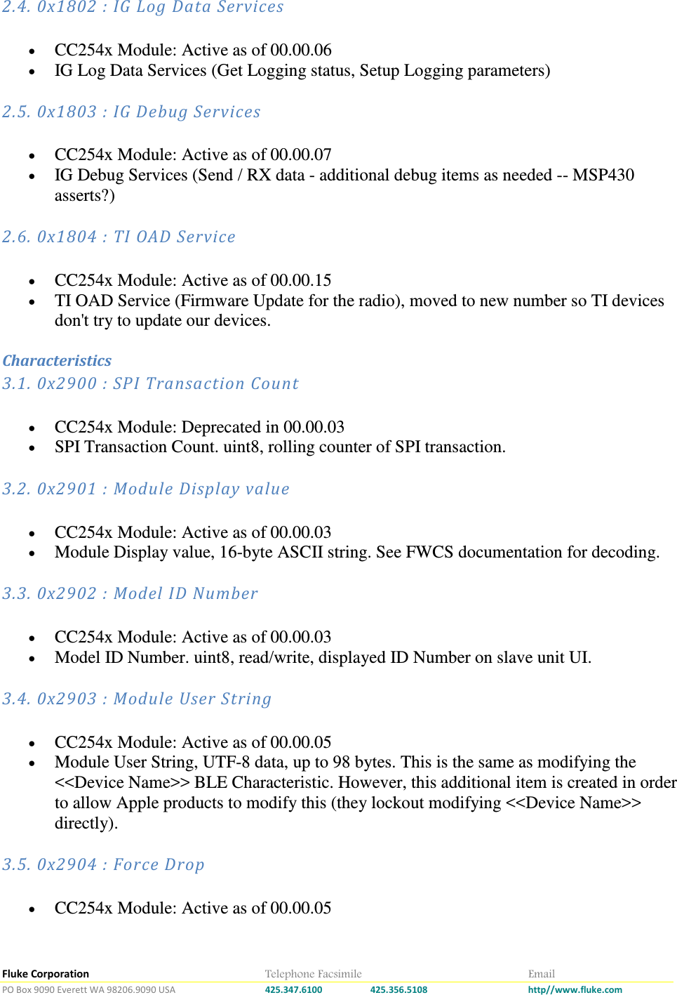
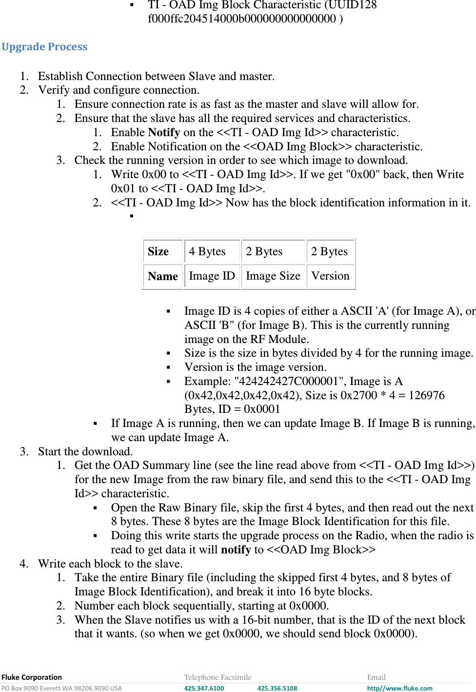
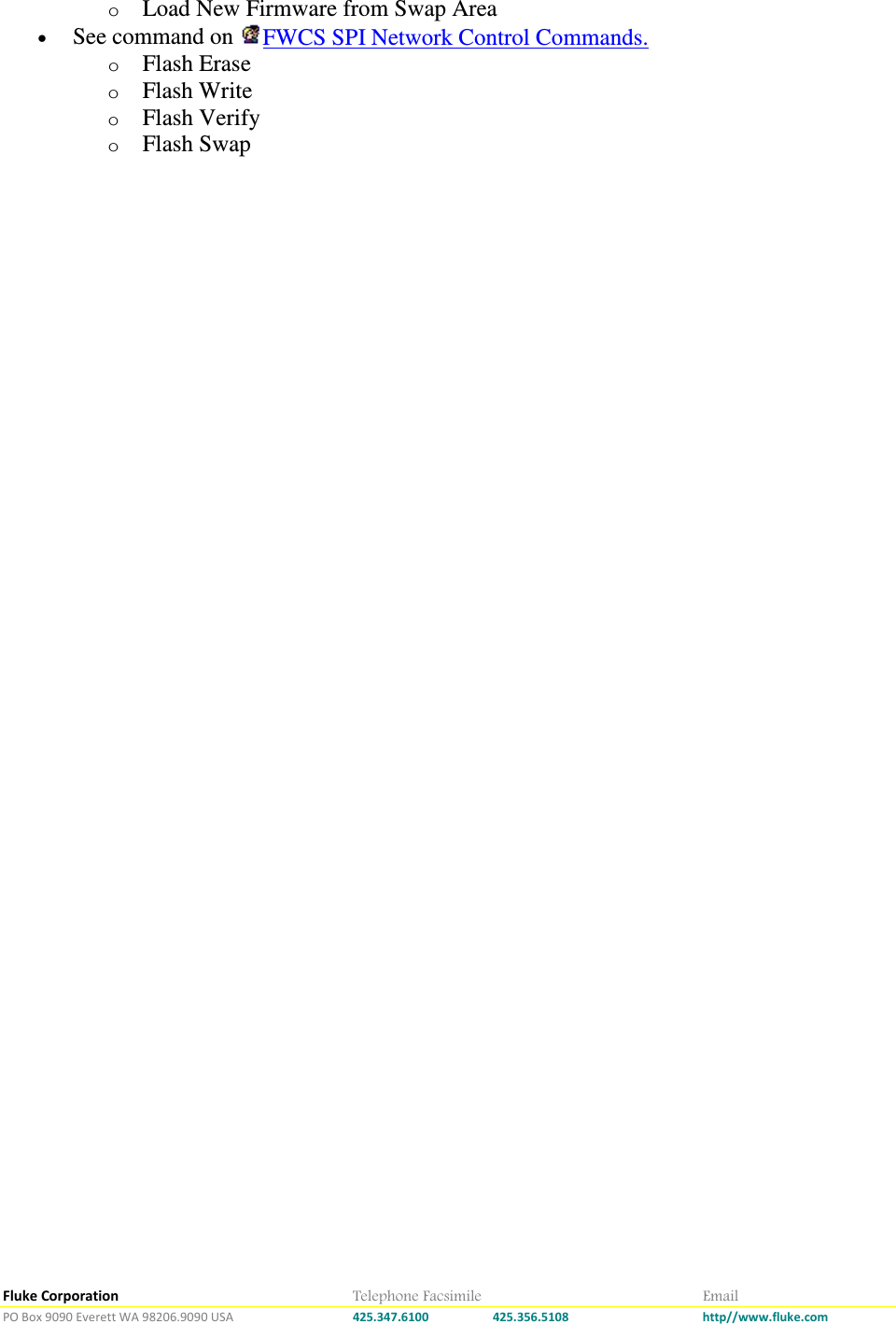
![Fluke Corporation Telephone Facsimile Email PO Box 9090 Everett WA 98206.9090 USA 425.347.6100 425.356.5108 http//www.fluke.com Cmd State 00 Return total Number of Bytes 01<state[1 byte unsigned int]> Lock the unit for bulk download, or unlock it. <state> should be 0x00 for unlock, and 0x01 for lock 02<startByte[4 byte, unsigned int]><endByte[4 byte, unsigned int]> System will notify back data in MTU packet sized from start byte to end byte. 03 Cancel download. If data is comming in and the master wants to stope the transfer, send this command • Notify Back: Bytes, in 1 to 18 bytes notify Chunks. Firmware Upgrade over BLE • The TI CC254x style upgrade is based on the idea of three sections in code. First off is a Boot Manager, which decided which image to run. This manager is never updated. The other two sections are labeled Image A, and Image B. On Power up the Boot manger decides which image to run. When it is time to update the device, the code in running image allows for the other image to be erased (in other words, if Image A is running, then you can only update Image B). Once Image B is updated and verified as good, Image A will be tweaked so it no longer passes the CRC check. Now the boot manger will run the newly updated Image B. On the next update, Image A will be erased, updated, and once verified.. run. Required Items • A Over the Air Upgrade File. o A Image A and Image B File, can be compiled with scons via "scons rf_module_imgA" or "scons rf_module_imgB" • System Hardware o A CNX Style slave unit, which can put the radio into a discoverable state. o A BLE Master device, capable to driving the process outlined below. • Firmware o RF Module with boot loader code present. o RF Module BLE Services. BLE Device Information Service ( UUID16 0x180A ). Firmware Characteristic (Which Identifies the running RF Module Code). TI OAD ( UUID128 f000180304514000b000000000000000 ) TI - OAD Img Id Characteristic (UUID128 f000ffc104514000b000000000000000 )](https://usermanual.wiki/Fluke-Electronics/FBLE.Module-Manual/User-Guide-2101604-Page-22.png)