Fluke 125 Brochure
2015-09-09
: Fluke Fluke-125-Brochure-808781 fluke-125-brochure-808781 fluke pdf
Open the PDF directly: View PDF ![]() .
.
Page Count: 5
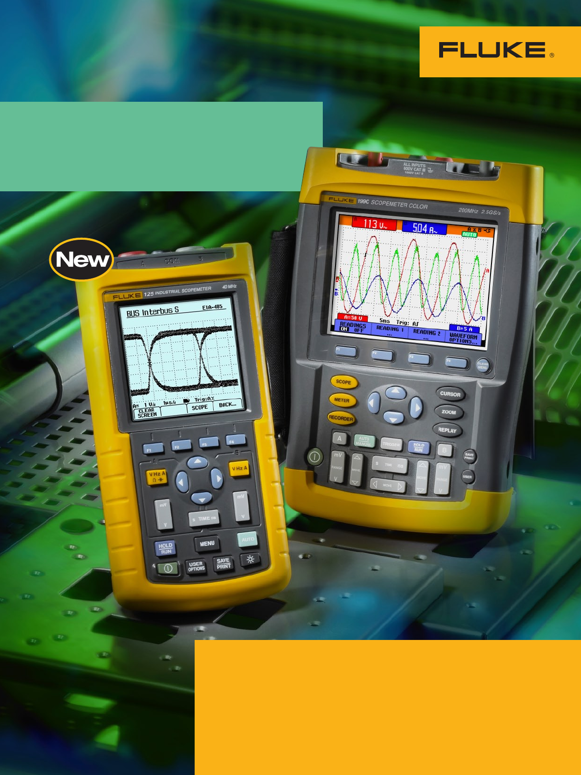
Powerful ScopeMeter® test capabilities:
• From 20 to 200 MHz bandwidth and up to 2.5 GS/s real-time sampling
• Up to seven hours operating time
• Now with FFT Analysis, advanced triggering and 3k memory length
Oscilloscopes for
field applications
High sampling rates give you the required
resolution for detailed signal analysis.
2
3
ScopeMeter® 190C and 190B Series:
Speed, performance and analysis power
For the more demanding applications, the ScopeMeter 190 Series high-
performance oscilloscopes offer specifications usually found on top-end bench
instruments. With up to 200 MHz bandwidth, 2.5 GS/s real-time sampling and
a deep memory of 27,500 points per input, they’re ideal for engineers who
need the full capabilities of a high-performance oscilloscope in a handheld,
battery powered instrument.
• Dual-input – 200, 100 or 60 MHz
bandwidth
• Up to 2.5 GS/s real-time sampling
per input
• Choice between a high-resolution
color display (190C Series) or black-
and-white display (190B Series)
• Connect-and-View™ automatic trig-
gering and a full range of manual
trigger modes
• Digital Persistence mode for analyz-
ing complex dynamic waveforms
like on an analog scope
• Fast display update rate for seeing
dynamic behavior instantaneously
• Automatic capture and replay of
100 screens
• 27,500 points per input record
length using ScopeRecord™ mode
• TrendPlot™ paperless chart recorder
for trend analysis up to 22 days
• Waveform reference for visual
comparisons and automatic pass/fail
testing of waveforms
• Vpwm function for motor drive and
frequency inverter applications
• Up to 1000 V independently
floating isolated inputs for
1000 V CAT II and 600 V CAT III
safety certification
• Four hours rechargeable NiMH
battery pack
See an on-line demonstration,
go to www.fluke.com/scopemeter
See what’s really happening
With a maximum real-time sampling
rate of 2.5 GS/s per input, you can
see what really happens, with 400 ps
resolution. Both inputs have their own
digitizer, so you can simultaneously
acquire two waveforms and analyze
them with the highest resolution
and detail. If an anomaly flashes
by on the screen, just press the Replay
button to see it again. And thanks to
the wider screen, you will always see a
12 divisions time window giving a far
better overview of what’s happening
both before and after the trigger event!
All this power in your hand
Thanks to the deeper memory, very small parts
of the waveform can be studied in full detail
using “zoom”.
Deeper waveform
acquisition memory
The waveform memory of all oscillo-
scopes in both the 190B and 190C
Series has been enlarged to allow as
many as 3000 samples per channel to
be acquired. You can use the ZOOM
function to find tiny details in a long
waveform, for example, the color burst
in a video signal or a single impulse in
a complex data-stream. All models also
allow the high-resolution waveforms to
be transferred to a PC for later detailed
analysis using FlukeView® ScopeMeter
software.
Easier identification of
traces, everywhere
The full-color display makes identifica-
tion of individual waveforms easier,
particularly when displaying large
amplitude or multiple overlapping wave-
forms on screen. On-screen color labels,
measurements and warnings are clearly
linked to specific waveforms.
See dynamic signal behavior
instantaneously
The Digital Persistence mode (Fluke
190C) helps to find anomalies and to
analyze complex dynamic signals by
showing the waveforms amplitude
distribution over time. Digital Persis-
tence uses multiple intensity levels and
user selectable decay time—it’s as
if you’re looking at the display of an
analog, real-time oscilloscope! The
fast display update rate that’s standard
on all models reveals signal changes
instantaneously, useful for instance
when making adjustments to a system
under test.
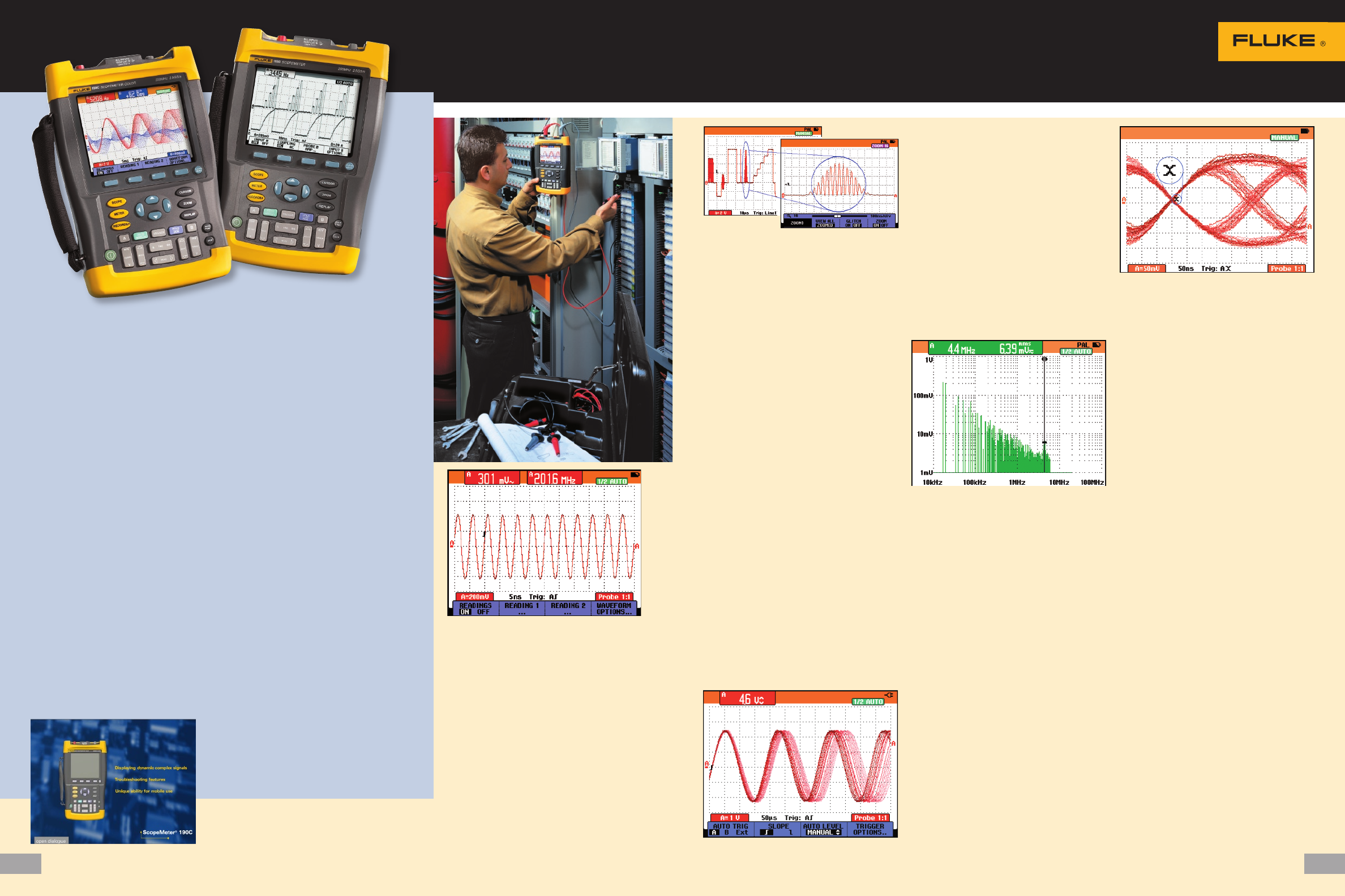
Frequency Spectrum shows an overview of
frequencies contained in a signal.
Frequency spectrum analysis
All 190C color ScopeMeter models now
include Frequency Spectrum Analy-
sis functionality based on Fast Fourier
Transformation (FFT) analysis as a
standard feature. This enables you
to identify the individual frequency
components contained in a signal.
The spectrum analysis function is
also handy for revealing the effects
of vibration, signal interference or
crosstalk. An automatic window
function assures optimal window-
ing, although you may manually
select your preferred time window.
Dual-slope triggering used to capture the
eye-pattern on a digital datastream.
Advanced trigger modes
The ScopeMeter 190 Series simplifies
triggering with Connect-and-View™
automatic triggering. Two new modes
—“n-cycle triggering” and “dual-slope
triggering”—have been added to the
Fluke 190C Series to help you isolate
the phenomena of interest. N-cycle
triggering ensures you get a stable
live image of a signal, for example,
in-frequency dividers and clocked
(synchronous) digital systems, or
to synchronize on bursts of pulses.
Dual-slope triggering enables the oscil-
loscopes to trigger on both rising and
falling edges alike. This means that any
edge in the signal will act as a trig-
ger event and initiate a new waveform
acquisition, a most useful capabil-
ity when making eye-patterns from
digital data-streams, or in conjunction
with single-shot phenomena. Manual
modes include edge, delay, video and
pulse width triggering. A fully isolated
external trigger input is included for
troubleshooting time relationships
between two input signals synchro-
nized to a third signal.
Digital Persistence mode gives analog scope-
like display of complex and modulated signals.
ScopeMeter special value kit
FlukeView Software and the optically isolated
interface cable come as separate items, or as part of
the special value SCC-Kit. This kit contains:
• FlukeView Software (SW90W)
• Optically Isolated Interface Cable (for USB)
• Protective Hard-Shell Carrying Case (C190 or C120)
The SCC-kit can be ordered separately, or
with the main instrument by adding an “S”
to the main instrument type number, e.g.,
Fluke 199C/S (see Ordering Information
on back cover for more detailed information).
SCC120 Kit
SCC190 Kit
4
5
ScopeMeter® 190 Series
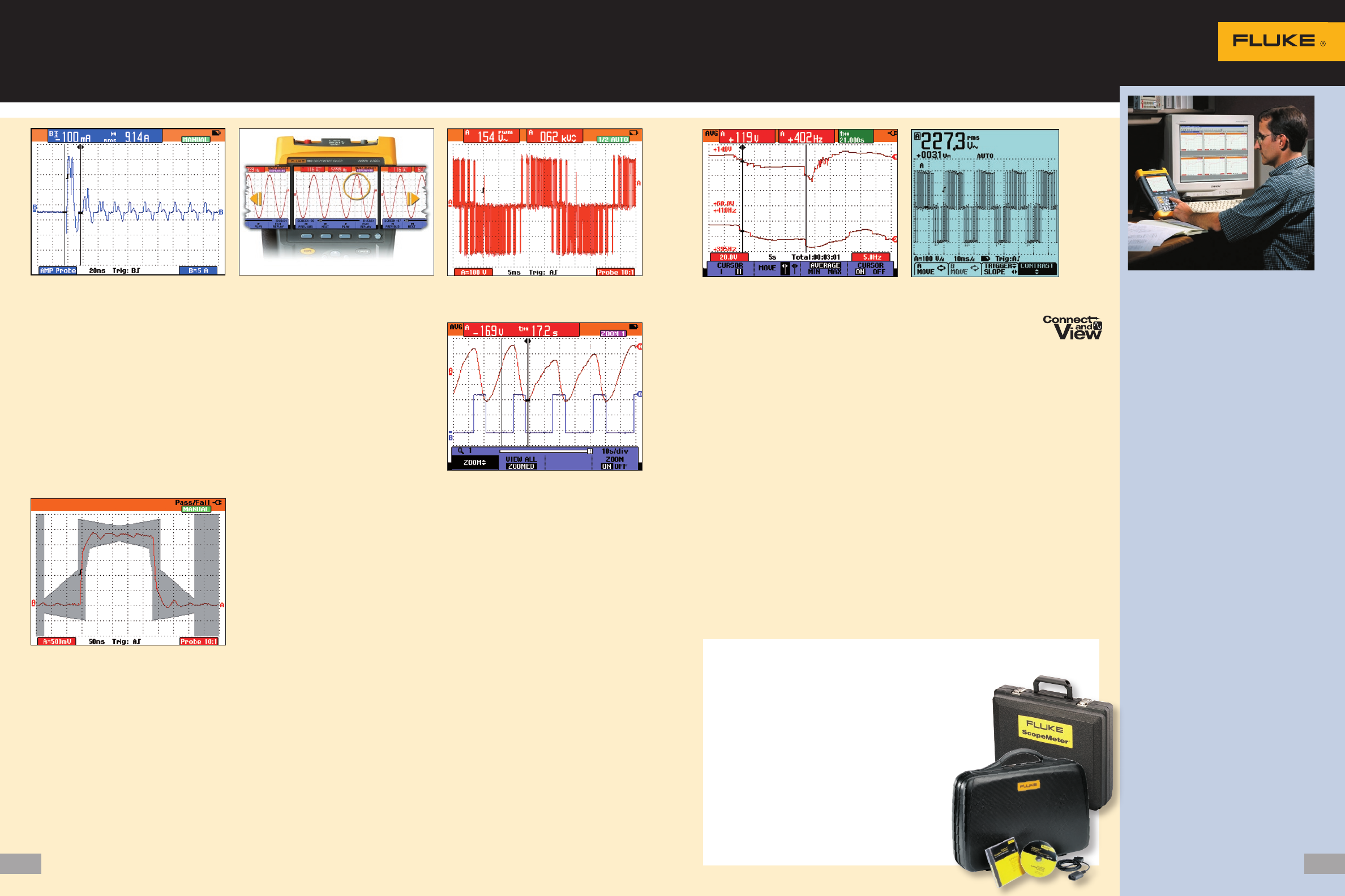
The inrush current is measured on the part of
the waveform enclosed by the cursors.
Cursor-limited
automatic measurement
ScopeMeter 190C and 190B features
30 automatic measurements, cursors,
zoom and real-time clock. Now auto-
matic power and Vrms-measurements
can be performed on a specific, user
identified portion of the waveform
using the cursors of the Fluke 190C
to define the time-window of inter-
est. In this way, the ScopeMeter 190C
measures the power within a specified
time span, or the rms-value of a volt-
age during a dedicated period of time.
Pass/Fail testing of actual signal against a
reference template
Waveform Pass/Fail Testing
“Waveform reference” allows an acquired
trace to be stored and designated “refer-
ence trace” for visual comparisons, or it
can be used as the reference for auto-
matic “Pass/Fail” testing (190C). Up to
100 individually matching (“Pass”) or
non-matching (“Fail”) waveforms can be
stored in the replay memory, allowing
you to monitor your system‘s behav-
ior over a long period of time, without
having to be present!
Automatic capture and replay
of 100 screens
Scope users know how frustrating it is to
see a one-time anomaly flash. Not with
the ScopeMeter 190 Series! Now you can
look back in time with a touch of the
replay button. In normal use, the instru-
ment continuously memorizes the last
100 screens. Each time a new screen is
acquired, the oldest is discarded. At any
moment, you can “freeze” the last 100
screens and scroll through picture-by-
picture or replay as a “live” animation.
Cursors can be used for further analysis.
Use the advanced trigger capabilities
to capture up to 100 specific events.
Two sets of 100 captured screens with
individual time stamps can be stored for
later recall or download to a PC.
Measure from mV to kV—
fully isolated and safely!
The ScopeMeter 190C and 190B series
have three independently floating
isolated inputs. While conventional
oscilloscopes can only make measure-
ments referenced to the line power
ground, measurements on each of the
Fluke ScopeMeter 190 series inputs
can be referenced to a different “low”
level. This enables measurements in
mixed circuits having different ground
references, and also eliminates the risk
of accidental ground short circuits. All
inputs are safety certified for measure-
ments in 1000 V CAT II and 600 V
CAT III environments. And the standard
probes cover a wide application range
from mV to kV, making the 190C and
190B ScopeMeter ideal for micro elec-
tronics to electrical applications.
Use the 27,500 points memory of ScopeRecord
and zoom in for maximum detail.
Deep memory for high-resolution
ScopeRecord™
The ScopeRecord memory stores 27,500
points per input or more, for high-
resolution recording of events up to 48
hours, and captures fast intermittents
and glitches as short as 50 ns. This
continuous roll mode stores events like
motion profiles, UPS, power supply and
motor start-ups. All models also have
a “Stop-on-Trigger” in the ScopeRecord
mode, allowing the ScopeMeter to store
waveform data until the instrument
is triggered or until a repetitive trigger
signal is interrupted. This way,
the instrument will automatically
recognize a power failure and store the
waveform data preceding it. With
100 x zoom, you can look at the small-
est details, like individual power cycles.
Two of these 27,500 point record-
ings can be stored for later analysis.
Vpwm measures effective voltage on motor drive
and frequency inverter outputs. Cursors and zoom featured by the 190 Series
help you to analyze the captured TrendPlot.
Use TrendPlot™ to help
find intermittents, fast
The toughest faults to find are those
that happen only once in a while
—intermittents. They can be caused by
bad connections, dust, dirt, corrosion
or simply broken wiring or connectors.
Other factors, like line outages and sags
or the starting and stopping of a motor,
can also cause a machine to stop. You
may not be around to see it your Fluke
ScopeMeter will. In this “paperless
recorder” mode, you can plot the mini-
mum and maximum peak values and
average over time up to 16 days. The
two inputs can plot any combination
of volts, amps, temperature, frequency
and phase – with time and date stamp
—to help lead you to the cause of those
faults quickly.
Connect-and-View captures even
the most complex motor drive signals.
Connect-and-View™
triggering for an
instant, stable display
Scope users know how difficult trig-
gering can be. Incorrect settings show
unstable and sometimes incorrect
results. The unique Connect-and-View
function recognizes signal patterns and
automatically sets up correct triggering.
It provides a stable, reliable and repeat-
able display of virtually any signal,
including motor drive and control
signals, without touching a button.
Signal changes are instantly recog-
nized and settings adjusted for a stable
display. Benefit from the speed and
convenience when measuring a number
of test-points in quick succession.
FlukeView®
Software for
documenting,
archiving and
analysis
FlukeView for Windows®
helps you get more out of
your ScopeMeter by:
• Documenting – transfer waveforms,
screens and measurement data from
the ScopeMeter to a PC. Print or
import the data into your report.
• Adding user text to individual
ScopeMeter settings – provid-
ing guidance to the operator when
recalling a set-up.
• Archiving – create a library of
waveforms with your comments
for easy reference and comparison.
Store complete Replay cycles for
analysis of waveform changes.
Store complete memory content of
the ScopeMeter on your PC for
back-up purposes.
• Waveform compare – store refer-
ence waveforms, add operator
instructions, and send both to the
ScopeMeter for waveform compari-
son and “Pass/Fail” testing.
• Analysis – use cursors, perform
spectrum analysis or export data to
other analysis programs.
• Connection to a PC via an optically
isolated interface cable –
Software and cable come as separate
items or as part of a special value
kit. This kit also includes a protective
hard shell carrying case for safe and
convenient storage of instrument and
accessories.
ScopeMeter® 120 and 190 Series common functions
Software and special value kits.
6
7
ScopeMeter® 120 Series:
As simple as one-two-three
The compact ScopeMeter 120 Series is the rugged solution for industrial trou-
bleshooting and installation applications. It’s a truly integrated test tool, with
oscilloscope, multimeter and “paperless” recorder in one affordable, easy-to-
use instrument. Find answers fast to problems in machinery, instrumentation,
control and power systems.
• Dual-input 40 MHz or 20 MHz
digital oscilloscope
• Two 5,000-count true-rms digital
multimeters
• Automatic measurements
• A dual-input TrendPlot™ recorder
• Connect-and-View™ trigger
simplicity for hands-off operation
• Shielded test leads for oscillo-
scope, resistance and continuity
measurements
• 10:1 Voltage Probe included with
Fluke 124 and 125 for reduced
circuit loading
• Up to seven hours battery operation
• 600 V CAT III safety certified
• Optically isolated interface
• Rugged compact case
• New Fluke 125 gives bus health and
power measurements
New! Fluke 125
Industrial ScopeMeter®
In today’s complex systems, a meter
measurement just doesn’t give enough
detail to determine the cause of a fault.
Signal anomalies, dropouts and glitches
that might cause a machine to go down
are best captured with an oscilloscope.
The ScopeMeter 120 Series meets
today’s need of simultaneously measur-
ing and checking waveforms. The
unique Connect-and-View™ triggering
automatically displays stable wave-
forms of virtually any signal. It really
is as easy as one-two-three!
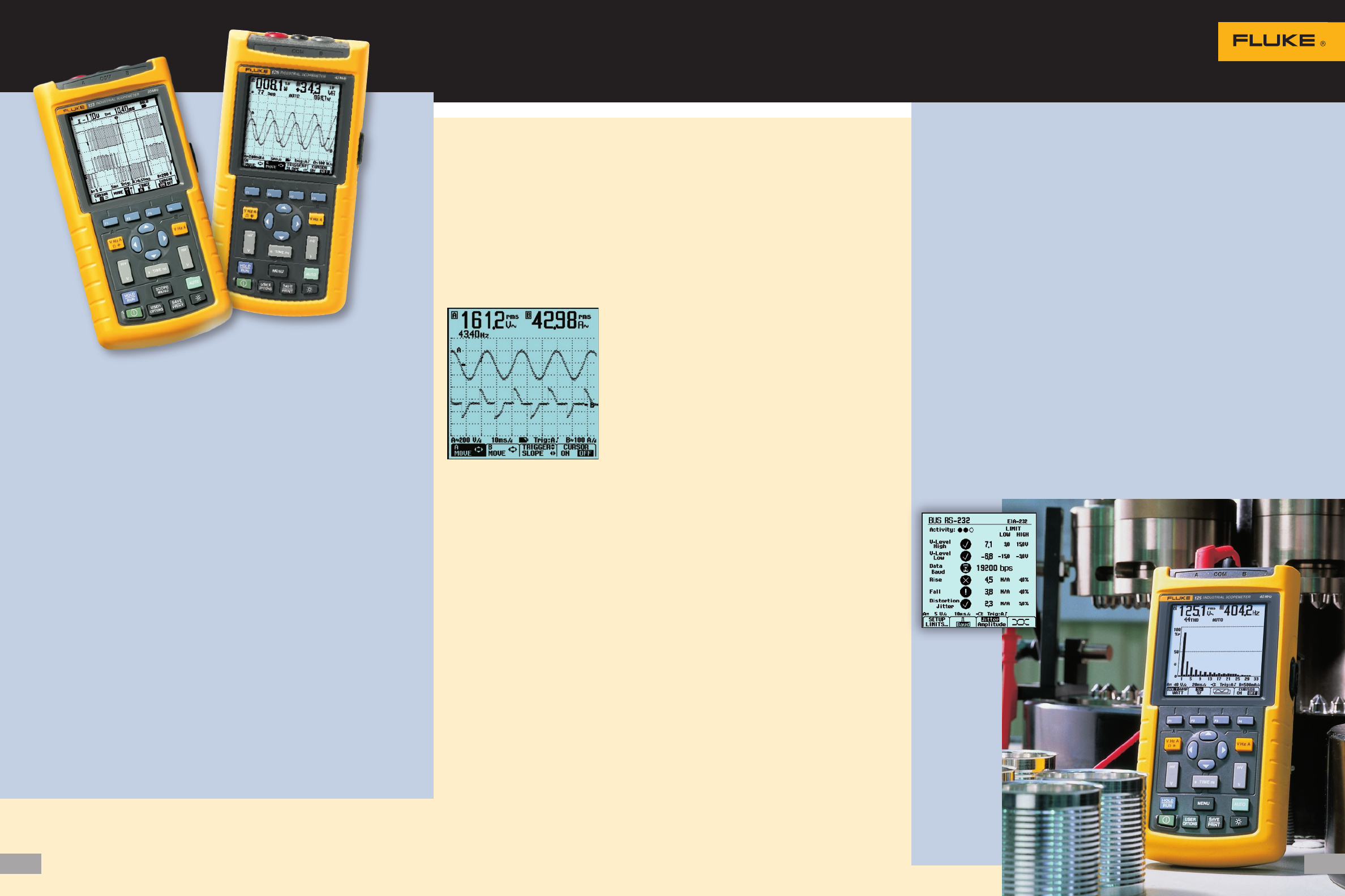
Dual-input measurement shows both meter
reading and waveform at the same time.
Scope mode
With bandwidth of 20 MHz (Fluke 123)
or 40 MHz (Fluke 124, 125) the
Fluke 120 Series will capture and
display almost any waveform found
in today’s state-of-the-art industrial
electronic or electro-mechanical
applications. Even complex signals
like variable frequency motor drives.
With Connect-and-View, it is as
simple as connecting to the test point
and letting the scope do the rest.
Meter mode
You don’t need to reach for another
test tool to make a simple resistance
measurement. The ScopeMeter 120
Series includes a multimeter on each
input. Measure volts (ac or dc), resis-
tance, capacitance, current via external
clamp or shunt, temperature using
an adapter or common time related
measurements like frequency, duty
cycle and more.
Working under time pressure and in
cramped or difficult-to-reach locations
means you want to focus on the job at
hand, not on the test tool in your hand.
That’s why the ScopeMeter 120 Series
has Connect-and-View automatic trig-
gering. You don’t have to worry about
triggering and instrument settings and
you have all the information on screen
to do the job right.
Battery powered mobility
Up to seven hours of battery operation
frees you from mains outlets for true
on-the-move working. The handheld
format and the weight of just 1.2 kg
(2.64 lbs) make the instrument easy
to carry and to fit comfortably in your
hand. The rugged and drip proof case
assures long life and reliable operation
in the harshest industrial environ-
ments. (See technical specifications for
details on battery life.)
Floating measurements,
safety certified
While conventional oscilloscopes can
only make measurements referenced to
power line ground, the Fluke 120 Series
makes floating measurements so there’s
no risk of an accidental ground short
circuit when making a connection.
The Fluke ScopeMeter 120 Series
test tools and the included shielded test
leads are safety certified for measure-
ments on 600 V CAT III industrial
power systems. Using the VPS40 probe,
measurements up to 1000 V CAT II are
fully supported. Via the optically isolated
interface, the ScopeMeter 120 can be
safely connected to a printer for direct
print-out or to a PC for later analysis
and documentation using FlukeView®
Software (for additional details about
FlukeView software see page 5).
Built to stand up to
harsh environments
The 120 Series Scopemeter is built to
hold up to every day use in the harsh-
est of industrial environments. The
case has been designed to withstand
extreme shock of vibration levels
tested to MIL-T-28800E Standards. The
ScopeMeter is also rated IP51, dust and
drip proof according to IEC 529.
Fluke 125 is the ScopeMeter of
choice for the maintenance engineer
who deals with industrial machinery
and the industrial network connect-
ing his plant processing equipment
and machinery.
The Fluke 125 has all the functionality
of the 124, plus it comes with the
following extensions:
• Bus Health mode gives a clear
“Good” / “Bad” indication for the
electrical signals on industrial buses
and networks, such as Foundation
Fieldbus CAN-bus, Profibus, Ether-
net, RS-232 and many more. The
Fluke 125 validates the quality of
the electrical signals on a network
segment. It checks the signal levels
and speed, transition times and
distortion, and compares these to
the appropriate standards to help
you find errors like improper cable
connections and terminators. It helps
you find the source of error in case
communication comes to a halt.
All the commonly found industrial
network types are supported!
• Power measurements for single
phase and balanced three-phase
systems. The Fluke 125 can display
the Total Power (Watts), Apparent
Power (VA), Reactive Power (VAR)
and the Power Factor (PF), over a
wide range of applied frequencies,
including those seen with motor
drives and inverters. As a result, you
are able to easily see the effects on
the various power measurements
during start-up or under changing
operational conditions. A current
clamp is included as a standard.
• Harmonics mode graphically
displays harmonics up to the 33rd
harmonic to assist in fault-finding,
e.g. with large non-linear loads.
See the technical datasheet at http://
us.fluke.com/usen/products/Fluke+120.
htm for more details on the Fluke 125.
Bus Health mode
allows for an
analysis of the
signal quality
on industrial
network,
comparing
measured
signals to the
standards’
signal
requirements.
Selection Table
Fluke 199C Color ScopeMeter (200 MHz / 2.5 GS/s)
Fluke 199C/S Color ScopeMeter (200 MHz / 2.5 GS/s) + SCC190
Fluke 196C Color ScopeMeter (100 MHz / 1 GS/s)
Fluke 196C/S Color ScopeMeter (100 MHz / 1 GS/s) + SCC190
Fluke 199B ScopeMeter (200 MHz / 2.5 GS/s)
Fluke 199B/S ScopeMeter (200 MHz / 2.5 GS/s) + SCC190
Fluke 196B ScopeMeter (100 MHz / 1 GS/s)
Fluke 196B/S ScopeMeter (100 MHz / 1 GS/s) + SCC190
Fluke 192B ScopeMeter (60 MHz / 500 MS/s)
Fluke 192B/S ScopeMeter (60 MHz / 500 MS/s) + SCC190
Fluke 125 Industrial ScopeMeter (40 MHz, with Bus Health)
Fluke 125/S Industrial ScopeMeter (40 MHz, Bus Health) + SCC120 kit)
Fluke 124 Industrial ScopeMeter (40 MHz)
Fluke 124/S Industrial ScopeMeter (40 MHz) + SCC120 kit
Fluke 123 Industrial ScopeMeter (20 MHz)
Fluke 123/S Industrial ScopeMeter (20 MHz) + SCC120 kit
SCC190 FlukeView® Software + Cable + Case (190 Series)
SCC120 FlukeView® Software + Cable + Case (120 Series)
OC4USB Optically-isolated USB-interface cable
PM9080 Optically-isolated RS-232 adapter/cable
SW90W FlukeView® ScopeMeter Software for Windows®
• ScopeMeter test tools come standard with a complete accessory package including line
voltage adapter and battery pack (installed). ScopeMeter 190B and 190C Series come
with probes, probe accessories and multimeter test leads.
• Optional accessories ordering information can be found in the technical datasheet or
on the Fluke web site.
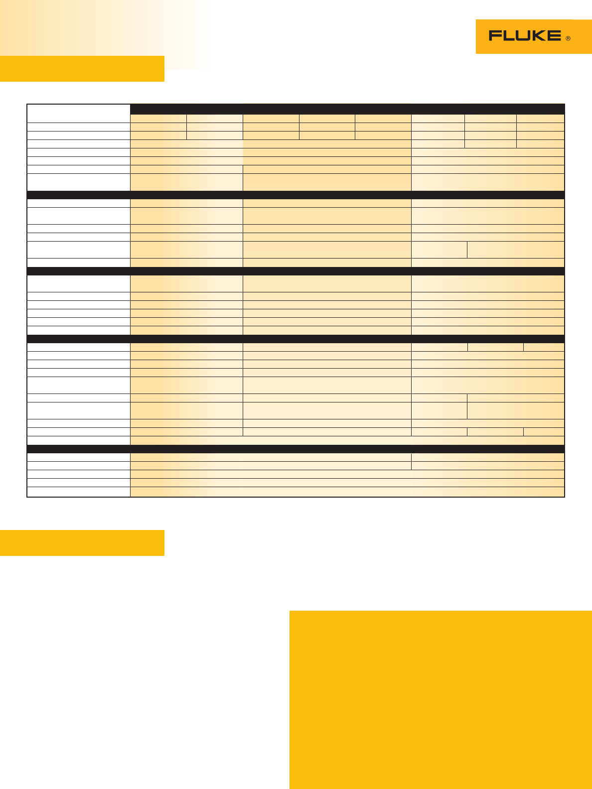
Ordering information
Bandwidth
Max. real time sample rate
Equivalent time sample rate
Max. record length (per input)
Number of inputs
Input sensitivity
Independently floating
isolated inputs
Display and Display Modes
Display
Persistence
Envelop Mode
Waveform compare
FFT
Pass/Fail testing
Triggering
Connect-and-View™ Triggering
Edge, single, free run
Video
Video line select
Pulse width
External
Advanced Functions
Cursors
Zoom
Dual Input TrendPlot™
ScopeRecord™ Mode
Automatic capture and replay
of last 100 screens
Bus Health test mode
Advanced Power
Measurements
Waveform mathematics
Save set-ups and screens
True-rms multimeter
Safety, Power and Warranty
Safety (EN61010-1)
Battery
Line power
PC and printer interface
Warranty
190C ScopeMeter Series 190B ScopeMeter Series 120 Series
Fluke 199C Fluke 196C Fluke 199B Fluke 196B Fluke 192B Fluke 125 Fluke 124 Fluke 123
200 MHz 100 MHz 200 MHz 100 MHz 60 MHz 40 MHz 40 MHz 20 MHz
2.5 GS/s 1.0 GS/s 2.5 GS/s 1.0 GS/s 500 MS/s 25 MS/s 25 MS/s 25 MS/s
(covered by real time sample rate) 2.5 GS/s 2.5 GS/s 1.25 GS/s
3000 points 512 points (min/max pairs)
2 scope inputs, 1 DMM input (all fully isolated from each other) 2 scope or DMM inputs
2 mV/div. to 100 V/div. 5 mV/div. to 100 V/div. 5 mV/div. to 50 V/div.
• • –
Color Monochrome Monochrome
Digital persistence with On/Off –
variable decay
• • •
visual + automatic visual only –
• – harmonics –
mode
• – –
• • •
• • •
• • •
• • •
• • –
• • Using optional ITP120
• • • • –
• • –
• • •
• • –
• • –
– – • –
• • • – –
• • –
10 10 20 20 10
5000 counts, measures volts – amps – ohms – continuity – diode – temperature
1000 V CAT II / 600 V CAT III certified 600 V CAT III certified (1)
4 hours, NiMH 7 hours, NiMH
Adapter/battery charger included
Using optional Optically Isolated interface cable (either RS-232 or USB) or PAC91 printer adapter cable
Three years on instrument / One year on standard accessories
(1) Maximum input voltage 1000 V CAT II with VPS40, 40 MHz, 10:1 Voltage Probe (standard included with Fluke 125 and Fluke 124)
Detailed technical specifications and optional accessories can be found in the technical datasheet and on the Fluke web site.
120 and 190 Series ScopeMeter® Test Tools
Fluke Corporation
PO Box 9090,
Everett, WA USA 98206
Fluke. Keeping your world up and running.™
Fluke Europe B.V.
PO Box 1186, 5602 BD
Eindhoven, The Netherlands
For more information call:
In the U.S.A. (800) 443-5853 or Fax (425) 446-5116
In Europe/M-East/Africa +31 (0) 40 2675 200 or Fax +31 (0) 40 2675 222
In Canada (800)-36-FLUKE or Fax (905) 890-6866
From other countries +1 (425) 446-5500 or Fax +1 (425) 446-5116
Web access: http://www.fluke.com
©2004, 2007 Fluke Corporation. All rights reserved.
Specifications subject to change without notice.
Printed in U.S.A. 2/2007 1629090 B-EN-N Rev E
