Fluke 190 202 Application Note
2015-09-09
: Fluke Fluke-190-202-Application-Note-808698 fluke-190-202-application-note-808698 fluke pdf
Open the PDF directly: View PDF ![]() .
.
Page Count: 3

There’s probably not a service
engineer on the planet that
wouldn’t agree that intermit-
tent electrical faults are the
most difficult and frustrating to
trace and solve. Although these
may seem like random disas-
ters sent to test our patience,
invariably they have a sound
physical cause. The trick, of
course, is to discover what this
could be without spending
hours monitoring the offending
equipment until the elusive fault
finally chooses to show itself.
In this article, Henk ter Harm-
sel, Senior Product Specialist at
Fluke Industrial, The Nether-
lands, explains how the service
engineer’s life can be made
infinitely easier with the power-
ful troubleshooting features of
Fluke’s 190 Series II ScopeMeter.
Although usually highly
complex, modern electrical and
electronic equipment is also
incredibly robust, with masses
of protection circuitry to guard
against breakdown induced by,
for example, current and voltage
surges, mains harmonics, EMI…
you name it! This complexity, of
course, also has its down side
when it comes to maintenance.
Intermittent faults in particular,
always the curse of the service
engineer or technician, can
become a major headache to
trace in today’s ultra-sophis-
ticated systems with their fast
and complex control signals.
Fortunately the situation is far
from hopeless since intermit-
tent faults share one infuriating
characteristic—despite their
apparent randomness, they all
fall into several well-defined
categories. This offers an impor-
tant clue to tracing and solving
them; a fact recognized by Fluke
when designing its 190 Series II
ScopeMeter.
Troubleshooting with
the Fluke 190 Series II
ScopeMeter
Any number of factors can lead
to spurious signals that may
cause equipment to suddenly
drop out for no apparent reason.
Some of these are equipment
related, for example, defective
circuitry, dry solder joints, dust
or corrosion, and overheating.
Others, such as mains fluctua-
tions and voltage spikes due to
systems switching on, are
related to the mains supply.
Identifying the most likely cause
requires experience and intu-
ition and, in many instances, a
lot of luck.
Now, however, with the Fluke
190 Series II ScopeMeter, luck
doesn’t have to enter the equa-
tion. This family of handheld
test tools combines the func-
tions of digital multimeter with
a digital storage oscilloscope
in bandwidths up to 200 MHz
and with up to 2.5 GS/s real-
time sampling per channel. The
series also offers highly innova-
tive trouble-shooting features
found in the past only on very
expensive desktop oscilloscopes.
Available for the first time in a
portable instrument, these fea-
tures make the job of a service
engineer much easier, enabling
him or her to trace and solve all
manners of intermittent faults.
Tracking down faulty
wiring
The scope continuously records
the last 100 screens in First-in/
First-out (FIFO) memory. As soon
as you spot an anomaly on the
scope or suspect something has
occurred that you might have
missed, the Replay button can
be pressed to freeze the last 100
screens and allow you to play
them over again. The feature,
in fact, allows two sets of 100
screens with individual time
stamps to be stored for later
recall or downloaded to a PC for
a more detailed analysis.
The last 100 screens are
available for scroll-through pic-
ture by picture, or replayed as a
“live” animation.
Troubleshooting made
simple with the Fluke
190 Series II ScopeMeter®
The last 100 screens are available for scroll-through picture by
picture, or replayed as a “live” animation.
Application Note
From the Fluke Digital Library @ www.fluke.com/library
2 Fluke Corporation Troubleshooting made simple with Fluke’s 190 Series II ScopeMeter®
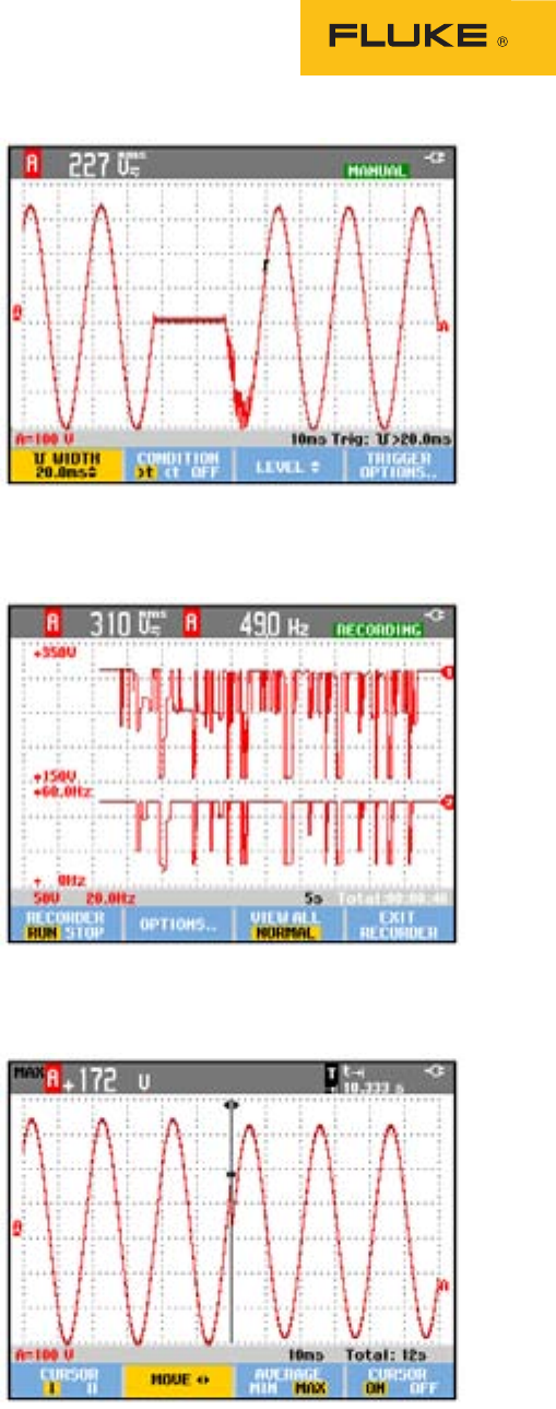
Catching signal
transients with capture
and replay
If you’re looking for a voltage
spike on the mains, for example,
the instrument should be set
to trigger on positive- or nega-
tive-going voltage pulses with
amplitude slightly larger than
mains voltage. This method can’t
be used, however, to capture
glitches that do not have voltage
levels higher than the signal
level. The solution then is to use
pulse-width triggering set to
capture, for example, negative-
going pulses with duration less
than a specified time. With the
200 MHz version (190 Series
II ScopeMeter), which has rise
and fall times of 1.7 ns, pulses
as narrow as 3 ns can easily
be captured using pulse-width
triggering. Setting the trigger to
capture negative-going pulses
that last longer than 20 ms can
also capture missing cycles on
the mains.
To see how often the event
occurs, just leave the ScopeMe-
ter connected to the circuit for as
long as you like then press the
Replay key to see and analyze
the captured events.
Looking for sags and
swells with TrendPlot™
The 190 Series II ScopeMeter’s
TrendPlot feature is used spe-
cifically for occasions in which
relatively long-term monitor-
ing is needed. Operating in the
ScopeMeter’s digital multimeter
mode, TrendPlot offers the ideal
way to locate causes of intermit-
tent problems that occur perhaps
only once an hour or once a
week. Besides ambient tempera-
ture fluctuations, voltage sags or
swells on the mains or a failing
power supply are other intermit-
tent problems that can be traced
with TrendPlot. In this mode,
the ScopeMeter acts in effect as
a paperless recorder, plotting for
more than 22 days the average,
minimum, and maximum values
of any selected scope or meter
measurement. Using this feature,
long-term irregularities can
easily be spotted. TrendPlot also
offers the important advantage
of accurate time stamping with
a resolution down to 0.2 sec-
onds to show exactly when an
irregularity occurs. This can be
displayed as either time-of-day
or elapsed time, depending on
the nature of the change you’re
trying to monitor.
While TrendPlot is running,
the ScopeMeter operates unat-
tended, continuously recording
the required data while
dynamically setting the vertical
ampli-tude scale to display the
maximum and minimum values,
and automatically compressing
the time scale to show the com-
plete trend from the start.
Analyzing fast, complex
electrical processes
Here’s where the 190 Series II
ScopeRecord mode comes in
handy. This is a continuous-
sampling mode in which the
scope records points (consist-
ing of minimum and maximum
values) at a rate of 125 MS/s.
With a 30,000-point deep
memory, the ScopeMeter can
record continuously in this
mode for up to 48 hours, captur-
ing glitches as short as 15 ns.
What’s more, a 100x zoom func-
tion makes the smallest details
visible, such as the shape of an
individual power cycle.
The figure shows what hap-
pens when an UPS switches
over from the inverter to mains
supply. Although the switcho-
ver would not be visible with a
normal display of say 200 ms/
div, captured with ScopeRecord;
the switchover is clearly visible
using a 100x zoom factor. In this
case, the display clearly shows
that no interruption in supply
has occurred, with the mains
voltage connected and in phase
within just a few milliseconds.
Setting the ScopeMeter to trigger on negative-going pulses longer
than 20 ms will detect missing cycles on the mains.
Plotting long-term irregularities with ScopeMeter’s TrendPlot
feature
ScopeRecord shows a voltage irregularity when switching off a UPS

3 Fluke Corporation Troubleshooting made simple with Fluke’s 190 Series II ScopeMeter®
An ideal partner
With the modern trend toward
ever faster, more complex elec-
tronic control systems, the need
for sophisticated test tools can
only increase. While advanced
bench-top instruments may offer
an impressive array of trouble-
shooting features, their price
and lack of portability generally
preclude their use by mobile
service engineers. They need
an instrument that can be easily
carried around and, since they
never know what to expect on a
call-out, preferably one with the
widest range of troubleshooting
features. The Fluke 190 Series II
ScopeMeter fulfills these needs
perfectly. Combining portabil-
ity with a range of advanced
features that are both power-
ful and intuitive to use, it’s the
ideal partner for today’s service
engineers and technicians who
work in the field.
Fluke Corporation
PO Box 9090, Everett, WA 98206 U.S.A.
Fluke Europe B.V.
PO Box 1186, 5602 BD
Eindhoven, The Netherlands
For more information call:
In the U.S.A. (800) 443-5853 or
Fax (425) 446-5116
In Europe/M-East/Africa +31 (0) 40 2675 200 or
Fax +31 (0) 40 2675 222
In Canada (800)-36-FLUKE or
Fax (905) 890-6866
From other countries +1 (425) 446-5500 or
Fax +1 (425) 446-5116
Web access: http://www.fluke.com
©2003-2011 Fluke Corporation.
Specifications subject to change without notice.
Printed in U.S.A. 4/2011 2127270B A-EN-N
Pub-ID 11790-eng
Modification of this document is not permitted
without written permission from Fluke Corporation.
Fluke. Keeping your world
up and running.®
