Fluke 323 Application Note
2015-09-09
: Fluke Fluke-323-Application-Note-807494 fluke-323-application-note-807494 fluke pdf
Open the PDF directly: View PDF ![]() .
.
Page Count: 6

Application Note
From the Fluke Digital Library @ www.fluke.com/library
Clamp Meter ABCs
With technological advances in
electrical equipment and circuits
come more challenges for elec-
tricians and technicians. These
advances not only require more
capability in today’s test equip-
ment, but more skills on the part
of the people who use them.
An electrician who has a good
grounding in the fundamentals of
test equipment use will be better
prepared for today’s testing and
troubleshooting challenges. The
clamp meter is a important and
common tool found in the tool-
boxes of electricians and techni-
cians alike.
A clamp meter is an electrical
tester that combines a voltme-
ter with a clamp-type current
meter. Like the multimeter, the
clamp meter has passed through
the analog period and into the
digital world of today. Originally
created primarily as a single-
purpose test tool for electricians,
today’s models have incorporated
more measurement functions,
more accuracy, and in some
instruments, some very special
measurement features. Today’s
clamp meters have most of the
basic functions of a digital multi-
meter (DMM), but with the added
feature of a current transformer
built into the product.
The transformer action
The ability of clamp meters to
measure large ac currents is
based on simple transformer
action. When you clamp the
instrument’s jaws or flexible
current probe around a conductor
What is a clamp meter and what can it do? What measurements
can be made with a clamp meter? How do you get the most
out of a clamp meter? Which clamp meter is best suited to the
environment the meter will be used in? The answers to these
questions can be found in this application note.
carrying ac current, that current
is coupled through the jaws,
similar to the iron core of a power
transformer, and into a second-
ary winding that is connected
across the shunt of the meter’s
input. A much smaller current
is delivered to the meter’s input
due to the ratio of the number
of secondary windings versus
the number of primary windings
wrapped around the core. Usu-
ally, the primary is represented
by the one conductor around
which the jaws or flexible current
probe is clamped. If the second-
ary has 1000 windings, then the
secondary current is 1/1000 the
current flowing in the primary, or
in this case the conductor being
measured. Thus, 1 amp of current
in the conductor being measured
Choose a clamp meter rated to meet the electrical environment you’ll be working in, as well as the resolution and
accuracy of measurement you’ll need for your testing.
2 Fluke Corporation Clamp Meter ABCs
would produce 0.001 amps or 1
milliamp of current at the input
of the meter. With this technique,
much larger currents can be
easily measured by increasing the
number of turns in the secondary.
Clamp meters measure any
combination of alternating and
direct current. This includes static
dc and charging dc as well as ac.
Clamp meters measure dc current
using Hall effect sensors. A Hall
effect sensor, basically a kind of
magnetometer, can sense the
strength of an applied magnetic
flux. Unlike a simple inductive
sensor, the Hall effect sensor will
work when the applied magnetic
flux is static, not changing. It will
work for alternating magnetic
fields as well. A clamp meter
contains a toroidal iron core that
clamps together with a Hall effect
chip in the gap between the
two halves, so that the induced
magnetic flux from the
current-carrying wire is
channeled through it.
Choosing your
clamp meter
Buying a clamp meter not
only requires looking at
specifications, but also looking
at features, functions, and the
overall value represented by a
meter’s design and the care taken
in its production.
Reliability, especially under
tough conditions, is more impor-
tant than ever. Fluke’s design
engineers make a point of
building these test tools not only
electrically, but also mechanically,
robust. By the time Fluke clamp
meters are ready to be tossed into
toolcases, they’ve undergone a
rigorous testing and evaluation
program.
User safety should be a primary
consideration in choosing a
clamp meter—or any other piece
of electrical test equipment. Fluke
not only designs its clamp meters
to the latest electrical standards,
but each clamp meter is indepen-
dently tested and then listed by
certified testing labs such as CSA,
TÜV, etc. Only with these certi-
fications can you be assured an
electrical tester meets these new
safety standards.
Using a clamp meter in
difficult situations
Electricians and technicians
often need to use clamp meters
in less-than-ideal situations.
The newest clamp meters use
the iFlex™ flexible current probe
to enable measuring where it’s
difficult to access—for example,
tight cabinets, bundled wires, or
awkward conductors.
When it’s necessary to measure
remotely, a clamp meter with a
detachable display (such as the
Fluke 381) makes it possible to
see the display at a location other
than where the measurement
is being taken. This means one
person—not two—can take the
measurement.
Resolution, digits and
counts
Resolution refers to how fine a
measurement a meter can make.
By knowing the resolution of a
meter, you can determine if it’s
possible to see a small change
in the measured signal. For
example, if the clamp meter has
a resolution of 0.1 amp on a 600
amp range, it’s possible to see a
change of 0.1 amp while reading
100 amps.
You wouldn’t buy a ruler marked
in one-inch segments if you had
to measure down to one-quarter
inch. Similarly, you must choose a
meter that can display the
resolution you need to see in
your measurements.
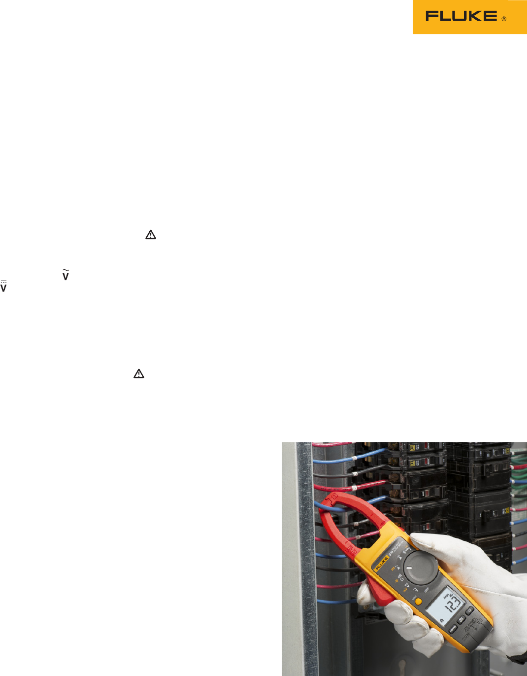
Use a flexible current probe for situations like this, where large conductors make it difficult
to use the clamp meter jaws.

3 Fluke Corporation Clamp Meter ABCs
Accuracy
Accuracy is the largest allow-
able error that will occur under
specific operating conditions.
In other words, it is an indica-
tion of how close the meter’s
displayed measurement is to the
actual value of the signal being
measured.
Accuracy for a clamp meter is
usually expressed as a percent
of reading. An accuracy of 3
% of reading means that for a
displayed reading of 100 amps,
the actual value of the current
could be anywhere between 97.0
and 103.0 amps.
Specifications may also include
a range of digits added to the
basic accuracy specification.
This indicates how many counts
the digit to the extreme right of
the display might vary. So the
preceding accuracy example
might be stated as ± (2 % + 2).
Therefore, for a displayed reading
of 100.0 amps, the actual current
could then be estimated to be
between 97.8 and 102.2 amps.
Crest factor
With the growth of electronic
power supplies, the current
drawn from today’s electrical
distribution system are no longer
pure 60 or 50 cycle sine waves.
These currents have become
fairly distorted, due to the
harmonic content these power
supplies generate.
However, electrical power
system components such as fuses,
bus bars, conductors, and thermal
elements of circuit breakers are
rated in rms current because
their main limitation has to do
with heat dissipation. If we want
to check an electrical circuit for
overloading, we need to measure
the rms current and compare the
measured value to the rated value
for the component in question.
Therefore, today’s test equip-
ment must be able to accurately
measure the true-rms value of a
signal regardless of how distorted
the signal might be.
Crest factor is a simple ratio of
a signal’s peak value to its rms
value. For a pure ac sine wave,
the crest factor would be 1.414.
However, a signal that has a
very sharp pulse would cause
the ratio, or crest factor, to be
high. Depending on the width of
the pulse and its frequency, you
can see crest factors of 10:1 or
higher. In real power distribution
systems, crest factors of greater
than 3:1 are rarely seen. So as
you can see, crest factor is an
indication of a signal’s distortion.
A crest factor specification will
be found only in specifications for
meters that can make true-rms
measurements. It indicates how
much distortion a signal can have
and still be measured within
the meter’s accuracy specifica-
tion. Most true-rms reading
clamp meters have crest factor
specifications of 2:1 or 3:1. That
rating will handle most electrical
applications.
Measuring current
One of the most basic measure-
ments of a clamp meter is current.
Today’s clamp meters are capable
of measuring both ac and dc
current. Typical current measure-
ments are taken on various
branch circuits of an electrical
distribution system. Determining
how much current is flowing in
various branch circuits is a fairly
common task for the electrician.
How to make current
measurements
1. Select Amps ac or Amps
dc .
2. Open the jaws of the clamp
meter and close the jaws
around a single conductor.
(If you are measuring ac
current, you can switch to
the iFlex setting and use a
flexible current probe.)
3. View the reading in the
display.
By taking current measurements
along the run of a branch circuit,
you can easily tell how much
each load along the branch
circuit is drawing from the
distribution system.When a circuit
breaker or transformer appears
to be overheating, it’s best to
take a current measurement on
the branch circuit to determine
the load current. However, make
sure you are using a true-rms
responding meter so you can get
an accurate measurement of the
signal heating up these compo-
nents. The average responding
meter will not give a true reading
if the current and voltage are non-
sinusoidal due to non-linear loads.
Measuring voltage
Another common function for a
clamp meter is measuring voltage.
Today’s clamp meters are capable
of measuring both ac and dc
voltage. AC voltage is usually
created by a generator and then
distributed through an electrical
distribution system. An electri-
cian’s job is to be able to take
measurements throughout the
system to isolate and fix electri-
cal problems. Another common
voltage measurement would be
testing battery voltage. In this
case, you would be measuring
direct current or dc voltage.
Testing for proper supply voltage
is usually the first thing measured
when troubleshooting a circuit. If
there is no voltage present, or if
it is too high or too low, the volt-
age problem should be corrected
before investigating further.
A clamp meter’s ability to
measure ac voltage can be
affected by the frequency of the
signal. Most clamp meters can
accurately measure ac voltages
with frequencies from 50 Hz to
500 Hz, but a digital multimeter’s
ac measurement bandwidth
might be 100 kHz or higher.
This is why the reading of the
same voltage by a clamp meter
and digital multimeter can have
very different results. The digital
multimeter allows more of the
high frequency voltage through to
the measurement circuitry, while
the clamp meter filters out some
of the voltage contained in the
signal above the bandwidth of
the meter.
When troubleshooting a vari-
able frequency drive (VFD), the
input bandwidth of a meter can
become very important in getting
4 Fluke Corporation Clamp Meter ABCs
a meaningful reading. Due to
the high harmonic content in the
signal coming out of a VFD to the
motor, a DMM would measure
most of the voltage content
(depending on its input band-
width). Measuring the voltage
output of a VFD is now a common
measurement. A motor connected
to a VFD only responds to the
average value of the signal, and
to measure that power the input
bandwidth of the clamp meter
must be narrower than its DMM
counterpart. The Fluke 375, 376,
and 381 clamp meters have been
specifically designed for testing
and troubleshooting VFDs.
How to make voltage
measurements
1. Select Volts AC ( ) or Volts DC
(), as desired.
2. Plug the black test probe into
the COM input jack. Plug the
red test probe into the V
input jack.
3. Touch the probe tips to the
circuit across a load or power
source (in parallel to the
circuit).
4. View the reading, being
sure to note the unit of
measurement.
5. (Optional) Press the HOLD
button to freeze the reading
in the display. Now you can
remove the meter from the
live circuit and then read the
display when you are safely
clear of the electrical hazard.
By taking a voltage measurement
at the circuit breaker and then
at the input of the load on that
breaker, you can determine the
voltage drop that occurs across
the wires connecting them. A
significant drop in voltage at the
load might affect how well the
load functions.
Measuring resistance
Resistance is measured in ohms
(Ω). Resistance values can vary
greatly, from a few milliohms
(mΩ) for contact resistance to
billions of ohms for insulators.
Most clamp meters measure down
to 0.1 Ω. When the measured
resistance is higher than the
upper limit of the meter, or the
circuit is open, “OL” appears in
the meter’s display.
Resistance measurements must
be made with the circuit power
off—otherwise, the meter or
circuit could be damaged. Some
clamp meters provide protec-
tion in the ohms mode in case of
accidental contact with voltages.
The level of protection may vary
greatly among different clamp
meter models.
How to make resistance
measurements
1. Turn off power to the
circuit.
2. Select resistance (W).
3. Plug the black test probe into
the COM input jack. Plug the
red test probe into the VW
input jack.
4. Connect the probe tips across
the component or portion of
the circuit for which you want
to determine resistance.
5. View the reading in the
meter’s display
Make sure the power is off
before making resistance
measurements.
Continuity
Continuity is a quick go/no-go
resistance test that distinguishes
between an open and a closed
circuit.
A clamp meter with a continuity
beeper allows you to complete
many continuity tests easily and
quickly. The meter beeps when
it detects a closed circuit, so you
don’t have to look at the meter as
you test. The level of resistance
required to trigger the beeper
varies from meter to meter. The
typical resistance setting to turn
on the beeper is a reading less
than between 20 ohms and
40 ohms.
Special functions
A fairly common measurement
function is reading the frequency
of an ac current waveform. With
the clamp meter’s jaws (or a
flexible current probe) wrapped
around a conductor carrying ac
current, switch on the Frequency
function and the meter’s display
will indicate the frequency of the
signal flowing in the conductor.
This is a very helpful measure-
ment when tracking down
harmonic problems in an electri-
cal distribution system.
Another feature that can be
found in some clamp meter
models is min, max, and aver-
age storage. When this feature is
activated, each reading the clamp
meter takes is compared against
any previously stored readings. If
the new reading is higher than
the reading in the high reading
memory, it replaces that reading
as the highest reading. The same
comparison is made against the
low reading memory, and the
new reading, if lower, replaces
the stored reading. The average
reading is updated accordingly.
As long as the min, max, and
average feature is active, all
readings are processed in this
way. Thus, after a period of time,
you can call up each of these
memory values to the display and
determine the highest, lowest,
and average reading over a
specific period of time.
In the past, not all clamp meters
could measure capacitance. The
Measuring current with a clamp meter.

5 Fluke Corporation Clamp Meter ABCs
capacitance measurement func-
tion is now being incorporated
into the feature set of many new
clamp meters. This function is
useful for checking motor start
capacitors or measuring values of
electrolytic capacitors contained
in controllers, power supplies
or motor drives.For electricians
who deal with motors in their
work, the ability to capture the
amount of current drawn by a
motor during its start up can tell a
lot about a motor’s condition and
loading. The Fluke 374, 375, 376,
and 381 clamp meters incorpo-
rate inrush current measurement
as part of their feature sets. After
clamping the jaws (or the flexible
current probe) around one of
the motor’s input leads, activate
the inrush mode. Next, turn on
the motor. The clamp meter’s
display will indicate the maxi-
mum current drawn by the motor
over the first 100 milliseconds
of its start cycle. This proprietary
inrush measurement technology
filters out noise and captures
motor starting current exactly as
the circuit protection sees it.
Clamp meter safety
Making measurements safely
starts with choosing the proper
meter for the environment in
which the meter will be used.
Once the proper meter has been
chosen, you should use it by
following good measurement
procedures.
The International Electrotechni-
cal Commission established new
safety standards for working on
electrical systems. Make sure you
are using a meter that meets the
IEC category and voltage rating
approved for the environment
where the measurement is to be
made. For instance, if a voltage
measurement needs to be made
in an electrical panel with 480V,
then a meter rated Category
III—600 V or higher should be
used. This means the input
circuitry of the meter has been
designed to withstand voltage
transients commonly found in this
environment without harming
the user.1 Choosing a meter with
this rating, which also has a CSA
or TÜV certification, means the
meter not only has been designed
to IEC standards, but has been
independently tested and meets
those standards. (See indepen-
dent testing sidebar).
Many new clamp meters
now carry a Cat IV safety rating,
which means they can be
used in outdoor or underground
settings where lightning strikes
or transients can occur more
frequently and at higher levels.
Safety checklist
✓ Use a meter that meets
accepted safety standards for
the environment in which it
will be used.
✓ Inspect test leads or flexible
current probe for physical
damage before making a
measurement.
✓ Use the meter to check
continuity of the test leads or
flexible current probe.
✓ Use only test leads that have
shrouded connectors and
finger guards.
✓ Use only meters with recessed
input jacks.
✓ Be sure the meter is in good
operating order.
✓ Always disconnect the “hot”
(red) test lead first.
✓ Don’t work alone.
✓ Use a meter that has overload
protection on the ohms func-
tion.
1See the ABCs of Multimeter Safety (literature
code 1263690) to learn more about IEC-1010
and how it applies to multimeter use.
Special features
The following special features
and functions may make it easier
to use your clamp meter.
• Annunciators (display icons)
show at a glance what is being
measured (volts, ohms, etc.)
• Data Hold allows you to freeze
the reading in the display.
• One-switch operation makes
it easy to select measurement
functions.
• Overload protection prevents
damage to both the meter and
the circuit, and protects the
user.
• Autoranging automatically
selects proper measurement
range. Manual ranging lets you
lock into a specific range for
repetitive measurements.
• Low battery indicator warns
you when the battery needs
changing.
• Display with backlight, easy-
to-read characters, and wide
viewing angle makes read-
ings easier to see in all sorts
of conditions. The backlight
display automatically sets the
correct measurement range so
you do not need to change the
switch positions while taking
a measurement.
• Integrated low pass filter and
state of the art signal process-
ing allows for use in noisy
electrical environments while
providing stable readings.

6 Fluke Corporation Clamp Meter ABCs
Glossary
Accuracy. How close the
displayed measurement is to
the actual value of the signal
being measured. Expressed as a
percentage of reading or a as a
percentage of full scale.
Analog Meter. An instrument
that uses a needle movement to
display the value of a measured
signal. The user judges the read-
ing based in the position of the
needle on a scale.
Annuciator. A symbol or icon that
identifies a selected range or a
function
Average Responding Meter.
A meter that accurately measures
sinusoidal waveforms, while
measuring non-sinusoidal wave-
forms with less accuracy.
Non-Sinudoidal Waveform.
A distorted waveform such as
a pulse train, square waves,
triangular waves, sawtooth waves
and spikes.
Resolution. The degree to which
small changes in a measurement
can be displayed.
RMS. The equivalent dc value of
an ac waveform.
Sinusoidal Waveform. A pure
sine wave without distortion.
True-rms Meter. A meter that
can accurately measure both
sinusoidal and non-sinusoidal
waveforms.
Independent testing is the
key to safety compliance
How can you tell if you’re getting a genuine
CAT III or CAT II meter? Unfortunately it’s not
always that easy. It is possible for a manu-
facturer to self-certify its meters as CAT II or
CAT III without any independent verification.
Beware of wording such as “Designed to meet
specification...” Designer’s plans are never a
substitute for an actual independent test. The
IEC (International Electrotechnical Commis-
sion) develops and proposes standards, but it
is not responsible for enforcing the standards.
Look for the symbol and listing number of
an independent testing lab such as UL, CSA,
TÜV or other recognized approval agency.
That symbol can only be used if the product
successfully completed testing to the agency’s
standard, which is based on national/inter-
national standards. UL 3111, for example,
is based on IEC 1010-1 2nd Edition. In an
imperfect world, that is the closest you can
come to ensuring that the multimeter you
choose was actually tested for safety.
Meter ratings and capabilities vary
by manufacturer. Before working with
a new meter, be sure to familiarize
yourself with all operating and safety
procedures for that meter contained in
the users manual.
LISTED
950 Z
R
Fluke Corporation
PO Box 9090, Everett, WA 98206 U.S.A.
Fluke Europe B.V.
PO Box 1186, 5602 BD
Eindhoven, The Netherlands
For more information call:
In the U.S.A. (800) 443-5853 or
Fax (425) 446-5116
In Europe/M-East/Africa +31 (0) 40 2675 200 or
Fax +31 (0) 40 2675 222
In Canada (800)-36-FLUKE or
Fax (905) 890-6866
From other countries +1 (425) 446-5500 or
Fax +1 (425) 446-5116
Web access: http://www.fluke.com
©2005-2010 Fluke Corporation.
Specifications subject to change without notice.
Printed in U.S.A. 10/2010 2562791C A-EN-N
Modification of this document is not permitted
without written permission from Fluke Corporation.
Fluke. Keeping your world
up and running.®
NOTE: The N number is different for each company i.e. Agilent, Fluke etc.
N10149
Preferred size Minimum size
Agilent
N10149
N10140
Preferred size Minimum size
Fluke
N10140
