Fluke 43B Application Note 2403028
2015-09-09
: Fluke Fluke-43B-Application-Note-809628 fluke-43b-application-note-809628 fluke pdf
Open the PDF directly: View PDF ![]() .
.
Page Count: 5
Application Note
Adjustable speed drives (ASDs)
can be both a source and a victim
of poor power quality.
ASDs as victim loads
Although ASDs are usually
depicted as the culprit in the PQ
scenario, there are ways in
which they can be a victim load
as well.
Capacitor switching transients
High-energy (relatively low-
frequency) transients that are
characteristic of utility capacitor
switching can pass through the
service transformer, feeders, and
converter front-end of the drive
directly to the dc link bus, where
it will often cause a dc link over-
voltage trip. Input diodes could
also be blown out by these tran-
sients.
Voltage distortion
If high-voltage distortion shows
up as excessive flat-topping, it
will prevent dc link capacitors
from charging fully and will
diminish the ride-through capa-
bility of the drive. Thus a voltage
sag which would not normally
affect a drive will cause the drive
to trip on undervoltage.
Improper grounding will
affect the internal control circuits
of the drive, with unpredictable
results.
ASDs as culprit loads
A drive can definitely be a “cul-
prit load” and have a major
impact on system PQ. But before
we talk of problems, let’s put in a
good word for the positive effects
of drives on PQ. First of all, they
offer built-in soft-start capabili-
ties. This means there will be no
From the Fluke Digital Library @ www.fluke.com/library
How adjustable
speed drives affect
power distribution
Line-side measurements on ASDs
Measurement Look for
Voltage waveform •Voltage notching (SCR converters)
•Flat-topping
Harmonic spectrum Harmonic orders and amplitudes, before and after filter
application
Displacement PF For PWM drives, DPF should remain high even at low speeds
(it will typically decrease slightly)
Voltage unbalance Less than drive manufacturer specs, or current overload trips
can result. The drive may have a higher limit for unbalance
than the motor.
Induction
Motor
M
Line
Reactors
inrush current and no voltage sag
effect on the rest of the system.
Secondly, if the drive is of the
PWM type, with a diode con-
verter front-end, the
Displacement Power Factor is
high (commonly > 95 % at rated
load) and more or less constant
throughout the range. This means
that drives can reduce energy
usage and correct for DPF at the
same time. It’s a good thing too,
because drives and PF correction
capacitors don’t mix. Caps are
vulnerable to the higher fre-
quency harmonic currents
generated by drives, since their
impedance decreases as fre-
quency increases.
The type of drive has a major
impact on the PQ symptoms,
because of the different converter
designs (converters or rectifiers
turn ac to dc and are the first
stage of the drive). There are two
major types of converter design.
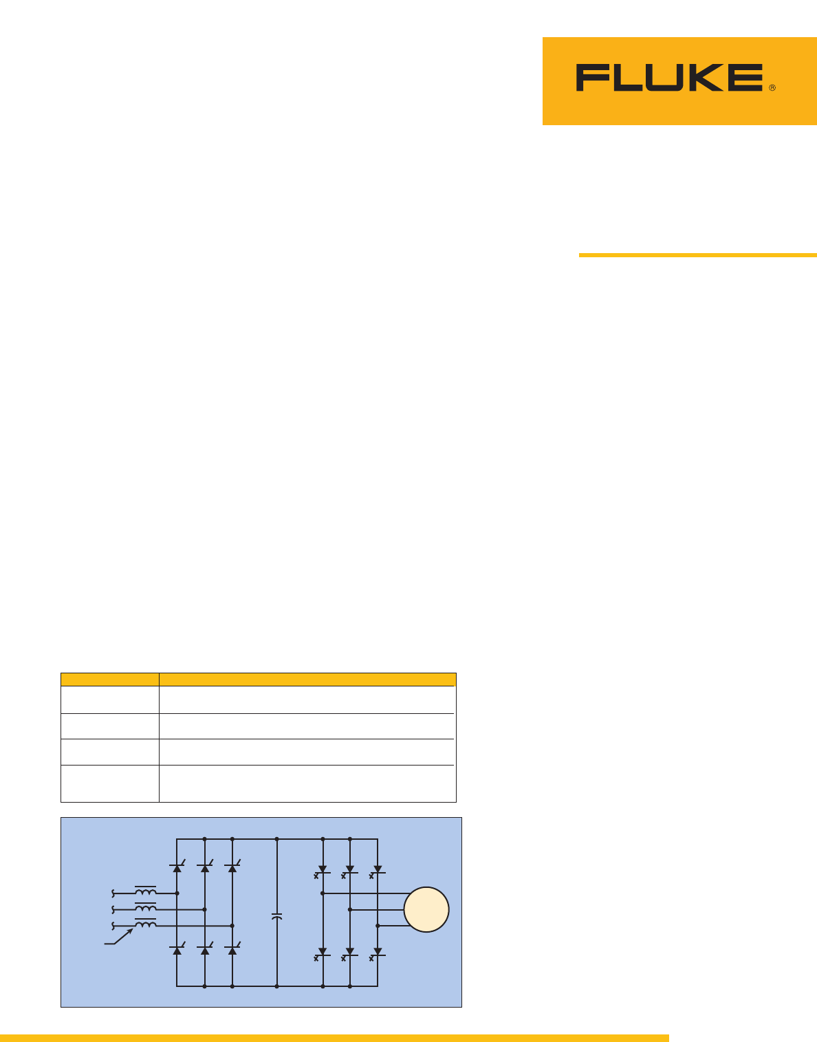
SCR convertor with
Voltage Source Inverter/
Variable Voltage Inverter
(VSI/VVI) drives
Commonly called six-step drives,
they use SCRs (Silicon -
Controlled Rectifiers) in their
converter front-ends (the follow-
ing discussion applies to CSI,
Current Source Inverter drives,
which also use SCRs). VSI and
CSI drive designs tended to be
applied on larger drives (> 100
HP). SCR converters control the
dc link voltage by switching on
(or “gating”) current flow for a
portion of the applied sine wave
and switching off at the zero-
crossing points. Unlike diodes,
SCRs require control circuits for
gate firing.
Figure 1. Voltage Source Invertor (VSI) ASD.
2 Fluke Corporation How adjustable speed drives affect power distribution
For the SCR converter, there
are three main issues that affect
line-side PQ:
•Commutation notches. SCR
switching or commutation is
such that there are brief
moments when two phases
will both be “ON.” This causes
what is in effect a momentary
short circuit that tends to col-
lapse the line voltage. This
shows up as “notches” on the
voltage waveform. These
notches cause both high V-
THD and transients. The
solution is to place a reactor
coil or isolation transformer in
series with the drive’s front
end to clean up both problems.
•Displacement Power Factor
declines as drive speed
decreases. This is not as seri-
ous a problem as it sounds,
because the power require-
ment of the drive-motor-load
decreases even more.
•Harmonic currents, typically
the 5th and 7th, are generated
by VSI drives.
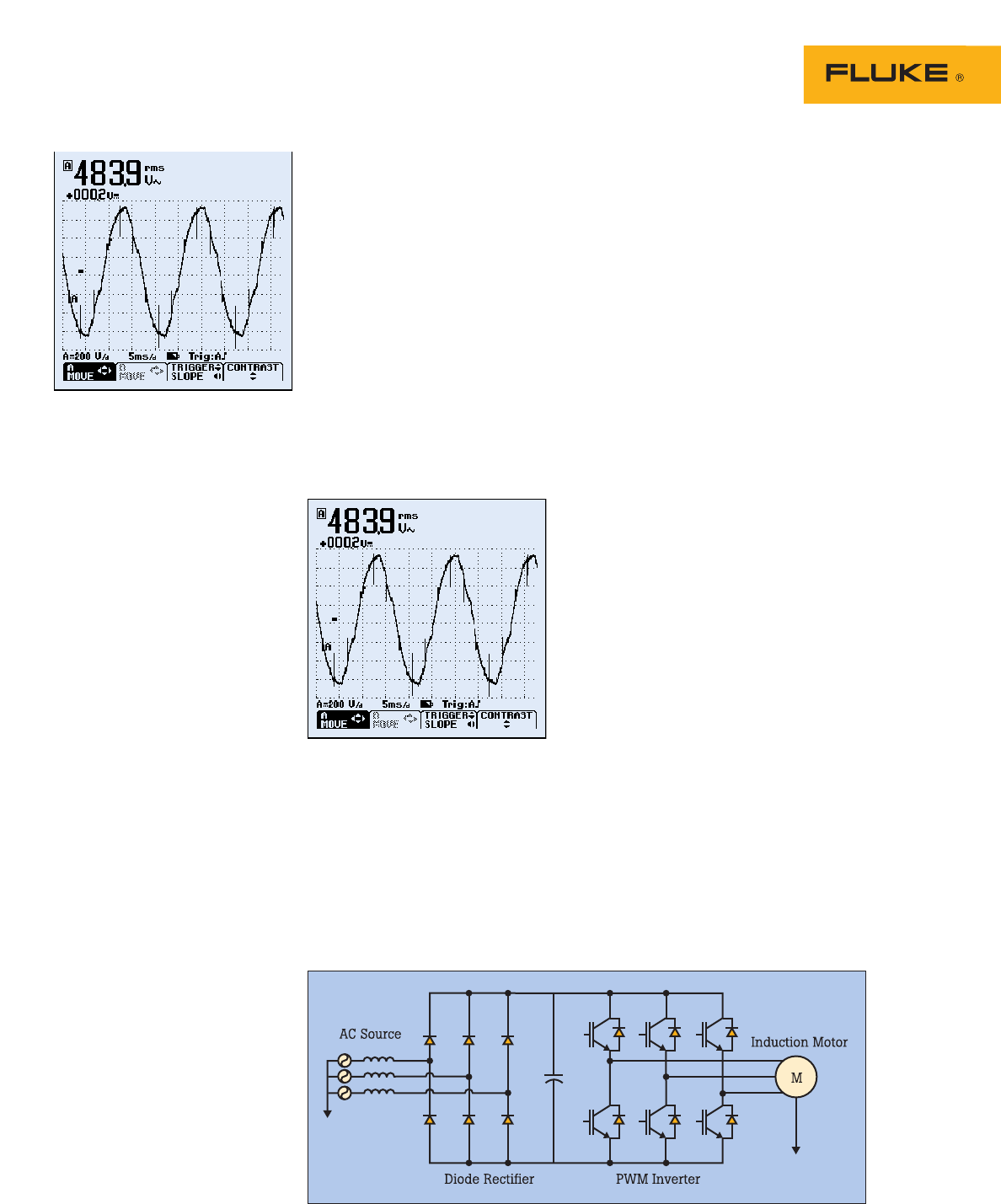
Diode convertor with
Pulse Width Modulation
(PWM) drives
The other and more common
converter design uses diodes and
is used in the PWM drive. The
diodes require no switching con-
trol circuitry. One of the main
trends in the industry has been
the proliferation of PWM drives,
mainly due to the continued
development of fast-switching,
efficient IGBTs (Insulated Gate
Bipolar Transistors) used in the
inverter section of the drive
(inverters turn dc to ac). For all
practical purposes, PWM drives
are the industry standard.
For the diode converter, the
main PQ issue is harmonics. The
actual harmonic orders being
generated depend on the number
of diodes in the front end. For
three-phase conversion, a mini-
mum set of six diodes is required.
This “six-pulse” converter will
generate 5th and 7th harmonics.
If a 12-pulse converter were
used, the 11th and 13th harmon-
ics will be generated instead of
the 5th and 6th — and, very
importantly, for the same load,
the amplitude of the 11th and
13th would be considerably less
than the 5th and 6th. Therefore,
the THD would be less. The vast
majority of drives, however, are
six-pulse PWM style, which is
one reason we see so much 5th
harmonic on the system.
Harmonics solutions
There are a number of solutions
to mitigating drive-generated
harmonics:
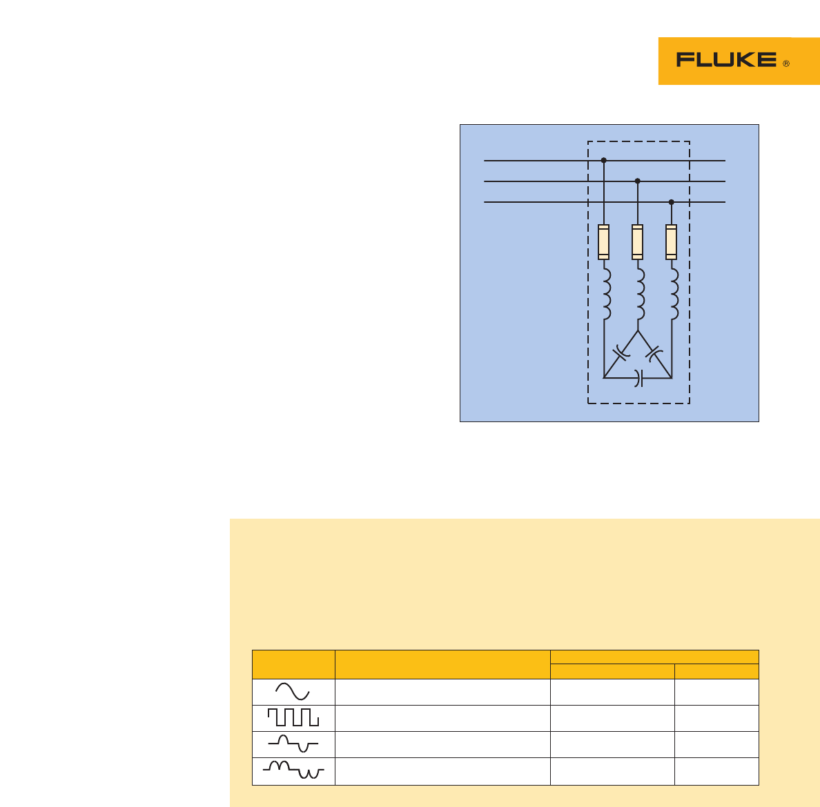
Harmonic trap filters (Figure 5)
These are typically LC networks
connected in parallel at the
source of the harmonics (in other
words, at the drive input). They
are tuned to just below the 5th
harmonic (typically 280 Hz) and
will tend to sink both 5th and
much of the 7th harmonic.
Obviously, they must be sized to
the harmonic-generating load.
Phase-shift transformers
This can be as simple as a delta-
wye transformer feeding one
drive(s) and a delta-delta feeding
another drive(s). There is a 30
degree phase shift effect
between these two configura-
tions, which effectively results in
cancellation of harmonics at the
closest upstream PCC (Point of
Common Coupling). The cancella-
tion effect is optimal when both
loads are more or less equal.
Figure 2. Voltage notching.
Figure 3. Typical ASD harmonic waveform.
Figure 4. Pulse Width Modulated (PWM) ASD.
3 Fluke Corporation How adjustable speed drives affect power distribution
12-pulse converter
If the delta-wye/delta-delta are
packaged together (delta primary,
delta and wye secondary) and
each secondary feeds one of two
paralleled six-pulse converters, a
12-pulse front-end is created
with all the benefits mentioned
above. 18-pulse designs are also
available. Because of the extra
cost, this type of solution tends to
only get used on high HP loads.
Active filters
This relatively new technology is
based on an elegant concept —
using power electronics to solve
the problems created by power
electronics. It senses the instan-
taneous ac sine wave; it then
actively cancels the harmonics it
detects by generating equal and
opposite polarity harmonics, thus
recreating the sine wave.
Commercial packages might pro-
vide voltage regulation as well.
Active PF correction
Another recent solution is for
manufacturers to offer converter
front ends using fast switching
technology that generates a mini-
mum amount of harmonics and
has near unity power factor (both
Total PF and DPF).
There is room for discussion
on which approach to harmonic
mitigation might prove most
effective and economical in a
particular situation. However,
what is often overlooked by the
end-user, and what should be
clear from the information in this
section, is that the total cost of a
drive system should include both
the cost of the drive itself and the
harmonic mitigation (whether
part of the drive or
installed separately).
A comparison of average-responding and true-rms multimeters
Multimeter Reading
Waveform Description Average-sensing DMM True-rms DMM
Sine wave Correct Correct
Square wave (flat-top voltage) 10 % high Correct
Current to single phase diode rectifier 40 % low Correct
Current to 3 phase diode rectifier 5-30 % low Correct
Why True-rms
True-rms test tools are necessary for accurate measurements of
distorted waveforms. For more information, see the Fluke application
note Why True-rms, document number 1260729.
LineLoad
Figure 5. Harmonic trap filter.
4 Fluke Corporation How adjustable speed drives affect power distribution
Is it possible to install “Power
Factor Correction Capacitors” and
have PF get worse? It certainly is,
and a starting place to under-
standing this puzzle lies in the
distinction between Displacement
PF (DPF) and Total Power Factor
(PF). The penalty for not under-
standing the difference can be
blown capacitors and wasted
investment.
Total PF and Displacement PF
are the same in one basic sense:
they are the ratio of Real Power
to Apparent Power, or Watts to
VA. DPF is the classic concept of
power factor. It can be considered
as the power factor at the funda-
mental frequency. Total Power
Factor, abbreviated to Power
Factor (PF), now includes the
effects of fundamental and of
harmonic currents (it is also
referred to as True PF or
Distortion PF, Figure 7). It follows
that with the presence of har-
monics, PF is always lower than
DPF and is also a more accurate
description of total system effi-
ciency than DPF alone.
Strictly speaking, the term
“Power Factor” refers to Total PF,
but in practice can also be used
to refer to DPF. Needless to say,
this introduces some confusion
into discussions of power factor.
You have to be clear which one
you’re talking about.
Displacement power
factor
Lower DPF is caused by motor
loads which introduce the need
for Reactive Power (Volt-Amp
Reactive or VARs). The system
has to have the capacity, meas-
ured in Volt-Amps (VA) to supply
both VARs and Watts. The more
VARs needed, the larger the VA
requirement and the smaller the
DPF. The cost of VARs is
accounted for in a power factor
penalty charge. Utilities often
levy additional charges for DPF
below a certain level; the actual
number varies widely, but typical
numbers are 0.90 to 0.95.
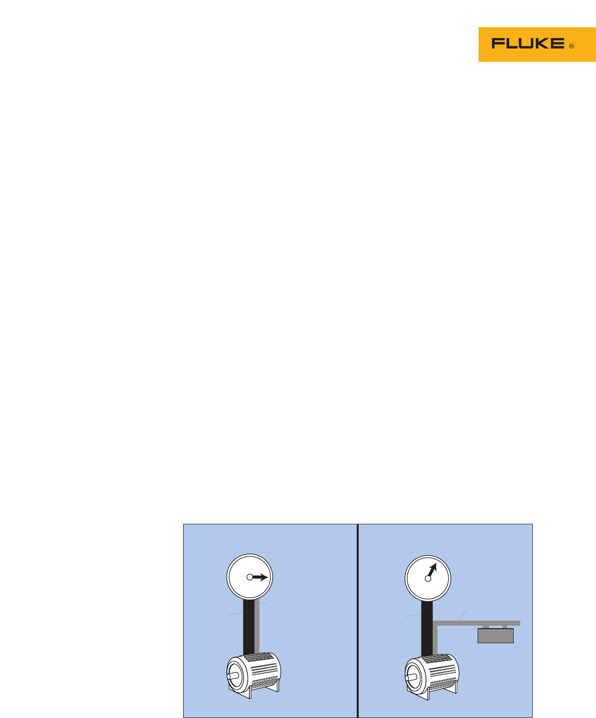
To reduce VARs caused by
motor loads, power factor correc-
tion capacitors are installed.
Upstream system capacity, both
in the plant and at the utility
level, is released and available
for other uses. (Figure 6)
Historically, this has been the
gist of the PF story: a relatively
well-known problem with a rela-
tively straightforward solution.
Harmonics and
capacitors
Harmonics have had a dramatic
impact on our approach to Power
Factor correction. The motor and
capacitor loads described above
are all linear and for all practical
purposes generate no harmonics.
Non-linear loads such as ASDS,
on the other hand, do generate
harmonic currents.
Take a plant which is step-by-
step putting adjustable speed
drives on its motor loads. ASDs
generate significant harmonic
currents (5th and 7th on six-
pulse converter drives). Suddenly
the fuses on existing PF correc-
tion caps start blowing. Since
these are three-phase caps, only
one of the three fuses might
blow. Now you’ve got unbalanced
currents, possibly unbalanced
voltages. The electrician replaces
the fuses. They blow again. He
puts in larger fuses. Now the
fuses survive, but the capacitor
blows. He replaces the capacitor.
Same thing happens. What’s
going on? Harmonics are higher
frequency currents. The higher
the frequency, the lower the
impedance of a cap (XC= 1/2πfC).
The cap acts like a sink for
harmonic currents.
Power system resonance
Hot vibes can result when harmonics and capacitors get together
After: PF = 100 %Before: PF = 42 %
1/6 HP Motor
Active
165 Watts
Reactive
360 VAR
3.3 A
1/6 HP Motor
Active
165 Watts
Reactive
360 VAR
1.4 A
Capacitor
60 µF
Figure 6. Capacitor corrects Displacement Power Factor (DPF).
5 Fluke Corporation How adjustable speed drives affect power distribution
many times greater than the
exciting current. This so-called
“tank circuit” can severely dam-
age equipment, and it will also
cause a drop in power factor.
Perversely, this resonant condi-
tion often appears only when the
system is lightly loaded, because
the damping effect of resistive
loads is removed. In other words,
we have what the audio buffs
call a “high Q” circuit. (Figure 8)
Imagine coming to work on a
Monday and seeing the insulation
on your cables melted off. How
can this happen over a weekend
when there was hardly any load
on the system? Has Ohm’s Law
been overruled? Not quite. Your
power system just spent the
weekend tanked out on the
Harmonics. It was quite a party,
but now comes the clean-up.
Start with harmonics
mitigation
The correct solution path starts
with measuring and mitigating
the harmonics generated by the
drives. Harmonic trap filters
would generally be called for.
These trap filters are installed
locally on the line side of the
drive. Their effect is very much
like the traditional PF correction
cap, in two senses: they reduce
DPF as well as PF, and also they
localize the circulation of the
problem harmonics (generally the
5th). Harmonics mitigation and
traditional DPF correction should
be addressed as one systems
issue. In other words, manage
Total PF, not just DPF.
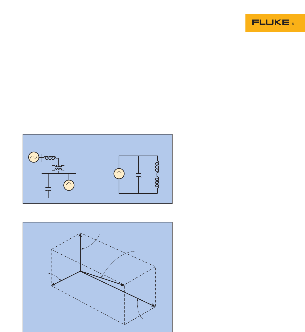
Power system resonance
In a worst-case scenario, the
inductive reactance (XL) of the
transformer and the capacitive
reactance (XC) of the PF correction
cap form a parallel resonant
circuit: XL= XCat a resonant
frequency which is the same as
or close to a harmonic frequency.
The harmonic current generated
by the load excites the circuit into
oscillation. Currents then circulate
within this circuit which are
Fluke Corporation
PO Box 9090, Everett, WA USA 98206
Fluke Europe B.V.
PO Box 1186, 5602 BD
Eindhoven, The Netherlands
For more information call:
In the U.S.A. (800) 443-5853 or
Fax (425) 446-51
16
In Europe/M-East/Africa (31 40) 2 675 200 or
Fax (31 40) 2 675 222
In Canada (800) 36-FLUKE or
Fax (905) 890-6866
From other countries +1 (425) 446-5500 or
Fax +1 (425) 446-5116
Web access: http://www.fluke.com
©2004 Fluke Corporation. All rights reserved.
Printed in U.S.A. 10/2004 2403028 A-US-N Rev A
Fluke. Keeping your world
up and running.
A. System Diagram B. Equivalent Circuit
Harmonic
source
XC
XTXT
XS
XS
XC
Figure 8. Resonant circuit when XC = (XT + XS)
kvar
(nonwork producing)
VA
kW
(work producing)
Harmonics
(nonwork
producing)
Figure 7. Total Power Factor increases with harmonics.
