Fluke 500 Series Users Manual
2015-09-09
: Fluke Fluke-500-Series-Users-Manual-805960 fluke-500-series-users-manual-805960 fluke pdf
Open the PDF directly: View PDF ![]() .
.
Page Count: 8

Manual Supplement
© 2015 Fluke Corporation. All rights reserved.
Manual Title: BT510 Users Supplement Issue: 1
Print Date: May 2014 Issue Date: 3/15
Revision/Date: Page Count: 7
This supplement contains information necessary to ensure the accuracy of
the above manual.
BT510 Users Manual Supplement
3/15 1
Change #1, 124
On pages 3-7, 3-8, 3-9, 3-10, 3-11 and 3-12, prior to How the Thresholds Work, replace with:
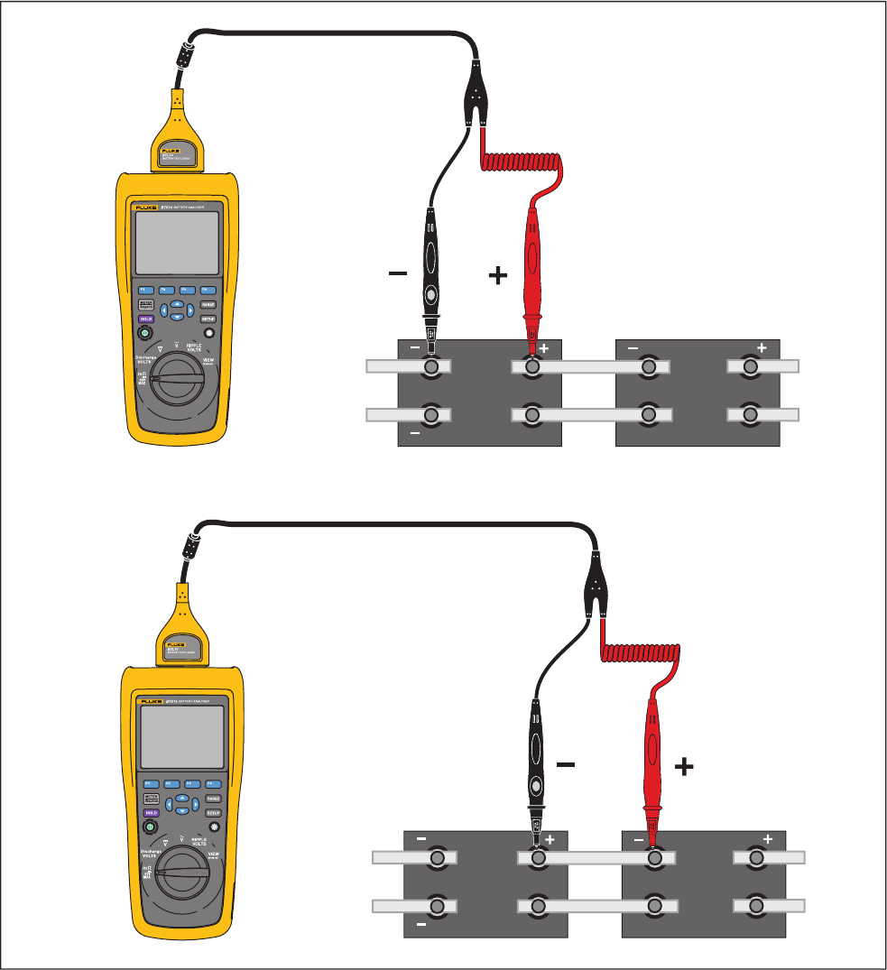
Make Measurements
Test Battery Internal Resistance and Voltage or Strap Resistance
The Product can simultaneously test the internal resistance and voltage of a battery.
This helps you to understand the overall state of the battery health. The Product can also test strap
resistance since upward changes could be caused by corrosion or loose connections.
To test battery internal resistance and voltage or strap resistance, turn the rotary switch to mΩ. See
Figure 3-1.
Manual Supplement BT510 Users
2 3/15
hsz018.eps
Figure 3-1. Test Battery Internal Resistance and Voltage or Strap Resistance
AB CD
AB CD
Strap Resistance
Internal Resistance and Voltage
BT510 Users Manual Supplement
3/15 3
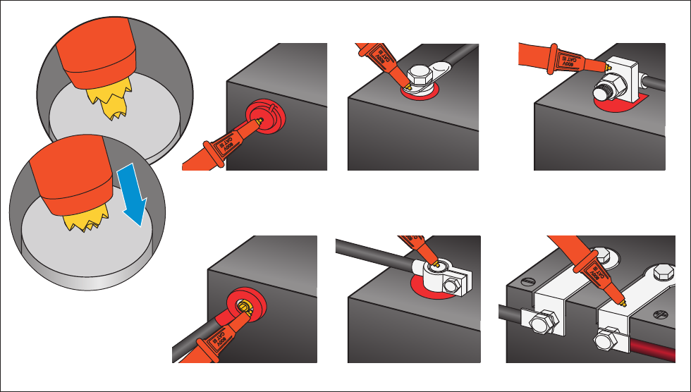
Battery Test Probes
To connect test probes to the battery pole:
1. Use the inner tip of the test probe to touch the target surface.
2. Push the test lead to set-back the inner tip, until both the inner tip and the outer tip are fully
connected to the target surface. This will ensure a proper 4-wire connection to the battery
terminal.
Note
Stable and correct readings are shown only when both the inner tip and the outer
tip of the test probe are fully connected to the battery posts. To get more
accurate battery internal resistance reading, do not connect the test probes to
screws. See Figure 3-2.
Examine for open fuse before mΩ measurement by connecting the outer tips of
both probes. If the mΩ reading changes from OL to dashes and then backs to
OL, the fuse is good. If mΩ reading remains as OL, the fuse is open and needs a
replacement.
In this function, the voltage between the positive and negative poles of a battery
must be < 60 V. A voltage >60 V causes the fuse to open.
hsz008.eps
Figure 3-2 Connect Test Probe to Battery
Small Hole Cylinder Screw Cube
Circle StripCylinder Clamp
Manual Supplement BT510 Users
4 3/15
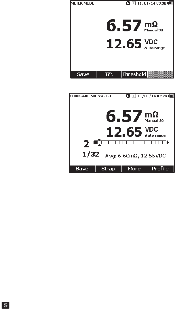
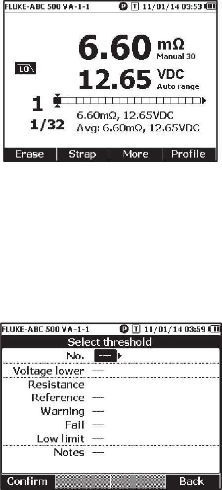
View Test Readings on the Screen
This is a typical display of battery test in Meter mode.
This is a typical display of battery test in Sequence mode:
Battery number: Indicates the number of the battery that has been tested.
Progress bar: The progress bar is generated according to the total number of batteries in the profile.
Each cell corresponds to one battery. An empty cell indicates the corresponding battery is not tested
yet. A full cell indicates the corresponding battery has been tested and the readings have been
saved. A cross mark in a full cell indicates that the threshold function is enabled.
Cursors: Use and to move the cursors. The number of the currently tested battery changes
accordingly. When the cursors are positioned on a full cell, the corresponding reading of that battery
will be shown under the progress bar.
Average readings: After two or more sets of test readings are saved, the Product shows the
average readings, including average resistance and average voltage.
Tip: If the test readings of a battery are significantly different from the average readings, it could
indicate the battery health has been compromised.
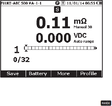
Measure Strap resistance in sequence mode
A strap string is created right behind battery string automatically in the same profile. The strap
number equals to battery number. Push the Strap softkey to switch to strap string test. The display
shows to indicate strap string. Push Battery softkey to switch back to battery string test.
B
T
3/
S
e
B
a
r
e
r
a
in
S
a
In
Al
th
p
r
E
r
T
o
1.
2.
A
c
E
x
m
r
e
T
o
in
T
510 Users
15
e
t Measure
m
a
ttery resist
a
e
sistance or
a
nges in this
auto rangin
a
ve Battery
Meter mod
e
l
l saved dat
a
e current re
s
r
ogress ba
r
m
If t
h
Sa
v
r
ase Test R
e
o
erase the
t
Use an
d
Push the
E
The pointe
d
c
tivate Low-
x
cessive hi
g
easuremen
t
e
sistance m
e
o
activate th
Sequence
m
m
ent Range
a
nce or Str
a
Strap resist
a
sequence:
3
g mode, an
d
Test Readi
n
e
, push the
S
a
is stored i
n
s
istance an
d
m
oves to th
e
h
e test lead
d
v
e function i
s
e
adings
t
est reading
s
d
to point
t
E
rase softk
e
d
cell beco
m
Pass Filter
f
g
h level of a
c
t
. Use the b
u
e
asurement
s
e low-pass
f
m
ode, push
a
p resistanc
e
a
nce meas
u
3
0 mΩ > 30
0
d
the range
n
gs
S
ave softke
y
n
chronologi
c
d
voltage re
a
e
right by o
n
d
oes not co
n
s
invalid.
s
for a certa
t
he cursors
t
e
y.
m
es empty.
P
f
or Resistan
c
c
ripple volt
a
u
ilt-in low p
a
s
.
f
ilter for batt
e
the More s
o
e
only has
m
u
rement is 3
0
0
mΩ > 300
0
cannot be c
y
to save th
e
c
al order. In
a
dings. The
n
e cell.
N
n
nect to bat
t
in battery in
t
o the cell th
a
P
ush the Sa
c
e Measure
m
a
ge can hav
e
a
ss filter to s
t
e
ry resistan
c
o
ftkey and p
5
m
anual rang
e
0
mΩ. You
c
0
mΩ > 3 m
hanged.
e
current re
s
Sequence
m
current seri
a
N
ote
t
ery or the t
e
Sequence
m
a
t correspo
n
ve softkey t
o
m
ent
e
a negativ
e
t
abilize or r
e
c
e measure
m
ush LO soft
e
s. The def
a
c
an push
Ω. The batt
e
s
istance, vo
l
m
ode, push
a
l number i
n
e
st lead is n
o
m
ode:
n
ds to the c
o
o
save new
e
impact on
t
e
duce the i
m
ment, in Me
t
key. The di
s
M
a
ult range fo
r
to cycle t
h
e
ry voltage
m
l
tage and ti
m
the Save s
o
n
creases by
o
t installed,
t
o
rrect batter
y
test readin
g
t
he battery r
m
pact of ac r
ter mode, p
u
s
play shows
M
anual Suppl
e
r
battery
h
rough di
f
fe
r
m
easureme
n
m
e.
o
ftkey to sa
v
1. The test
t
he
y
.
g
s for this b
a
esistance
ipple on
u
sh LO soft
k
the LO ico
n
e
ment
r
ent
n
t is
v
e
a
ttery.
k
ey,
n
.
Manual Supplement BT510 Users
6 3/15
Set Measurement Thresholds
The Product lets you define upper and lower measurement thresholds or tolerance ranges. These
defined threshold values are then compared to the measured values to automatically identify and
prompt the user with a PASS, FAIL or WARN indicator of battery out of tolerance conditions.
The threshold function is disabled by default. You can set up to 10 set of thresholds and select one
threshold as needed.
To set and select measurement thresholds:
1. On the measurement screen, push the More softkey and Threshold softkey to open the Select
Threshold menu.
2. Use and to select one threshold set out of ten.
3. Use and L to highlight the value to be edited among Voltage lower, Reference, Warning,
Fail, Low limit, and Notes.
4. Edit the selected field.
a. Use the – and + softkeys to change the values for Warning and Fail.
b. For other fields, push the Edit softkey, use the arrow keys to edit the value, and then push the
Confirm softkey to save the value.
5. Once all threshold values are correct, push the Confirm softkey on the save the threshold set.
The threshold set is applied and the T-X (X stands for value of No.) icon and the corresponding
PASS/WARN/FAIL indication shows on the display.
To disable measurement thresholds:
BT510 Users Manual Supplement
3/15 7
1. On the measurement screen, push the Threshold softkey to open the Select Threshold menu.
The value of No. is already highlighted.
2. Use to set No. to ---.
3. Push the Confirm softkey.
The T-X icon no longer shows on the display.
