Fluke 700Ptpk Users Manual 0master
2015-09-09
: Fluke Fluke-700Ptpk-Users-Manual-806528 fluke-700ptpk-users-manual-806528 fluke pdf
Open the PDF directly: View PDF ![]() .
.
Page Count: 34

April 2012 Rev. 1, 3/2014
© 2012-2014 Fluke Corporation. All rights reserved. Specifications are subject to change without notice.
All product names are trademarks of their respective companies.
700G Series
Pressure Gauge
Calibration Manual
LIMITED WARRANTY AND LIMITATION OF LIABILITY
Each Fluke product is warranted to be free from defects in material and workmanship under normal use and
service. The warranty period is three years and begins on the date of shipment. Parts, product repairs, and
services are warranted for 90 days. This warranty extends only to the original buyer or end-user customer of
a Fluke authorized reseller, and does not apply to fuses, disposable batteries, or to any product which, in
Fluke's opinion, has been misused, altered, neglected, contaminated, or damaged by accident or abnormal
conditions of operation or handling. Fluke warrants that software will operate substantially in accordance
with its functional specifications for 90 days and that it has been properly recorded on non-defective media.
Fluke does not warrant that software will be error free or operate without interruption.
Fluke authorized resellers shall extend this warranty on new and unused products to end-user customers
only but have no authority to extend a greater or different warranty on behalf of Fluke. Warranty support is
available only if product is purchased through a Fluke authorized sales outlet or Buyer has paid the
applicable international price. Fluke reserves the right to invoice Buyer for importation costs of
repair/replacement parts when product purchased in one country is submitted for repair in another country.
Fluke's warranty obligation is limited, at Fluke's option, to refund of the purchase price, free of charge repair,
or replacement of a defective product which is returned to a Fluke authorized service center within the
warranty period.
To obtain warranty service, contact your nearest Fluke authorized service center to obtain return
authorization information, then send the product to that service center, with a description of the difficulty,
postage and insurance prepaid (FOB Destination). Fluke assumes no risk for damage in transit. Following
warranty repair, the product will be returned to Buyer, transportation prepaid (FOB Destination). If Fluke
determines that failure was caused by neglect, misuse, contamination, alteration, accident, or abnormal
condition of operation or handling, including overvoltage failures caused by use outside the product’s
specified rating, or normal wear and tear of mechanical components, Fluke will provide an estimate of repair
costs and obtain authorization before commencing the work. Following repair, the product will be returned to
the Buyer transportation prepaid and the Buyer will be billed for the repair and return transportation charges
(FOB Shipping Point).
THIS WARRANTY IS BUYER'S SOLE AND EXCLUSIVE REMEDY AND IS IN LIEU OF ALL OTHER
WARRANTIES, EXPRESS OR IMPLIED, INCLUDING BUT NOT LIMITED TO ANY IMPLIED WARRANTY
OF MERCHANTABILITY OR FITNESS FOR A PARTICULAR PURPOSE. FLUKE SHALL NOT BE LIABLE
FOR ANY SPECIAL, INDIRECT, INCIDENTAL OR CONSEQUENTIAL DAMAGES OR LOSSES,
INCLUDING LOSS OF DATA, ARISING FROM ANY CAUSE OR THEORY.
Since some countries or states do not allow limitation of the term of an implied warranty, or exclusion or
limitation of incidental or consequential damages, the limitations and exclusions of this warranty may not
apply to every buyer. If any provision of this Warranty is held invalid or unenforceable by a court or other
decision-maker of competent jurisdiction, such holding will not affect the validity or enforceability of any other
provision.
Fluke Corporation
P.O. Box 9090
Everett, WA 98206-9090
U.S.A.
Fluke Europe B.V.
P.O. Box 1186
5602 BD Eindhoven
The Netherlands
11/99
i
Table of Contents
Title Page
Introduction ........................................................................................................ 1
How to Contact Fluke ........................................................................................ 1
Safety Information ............................................................................................. 2
Hazard Location Information/Approvals ....................................................... 2
Special Conditions for Safe Use .................................................................... 3
Symbols ......................................................................................................... 3
Specifications ..................................................................................................... 4
Available Input Ranges ................................................................................. 4
Accuracy 700G Ranges ................................................................................. 4
Accuracy 700RG Ranges .............................................................................. 4
Media Compatibility ...................................................................................... 4
Environmental ............................................................................................... 4
Mechanical Specifications ............................................................................. 5
Ranges and Resolution .................................................................................. 6
Maintenance ....................................................................................................... 7
How to Clean the Product .............................................................................. 7
How to Change the Batteries ......................................................................... 8
Performance Verification Tests ......................................................................... 9
Required Equipment ...................................................................................... 9
How to Verify Pressure ................................................................................. 9
Calibration Adjustment ...................................................................................... 16
Test Equipment .............................................................................................. 16
Connections ................................................................................................... 16
Enter 2-Point Adjust Mode ............................................................................ 16
Full Adjust ..................................................................................................... 17
Procedure Example ........................................................................................ 17
Serial Interface ................................................................................................... 20
List of Commands ......................................................................................... 21
Parameter Units ............................................................................................. 22
Error Codes .................................................................................................... 23
Replacement Parts and Accessories ................................................................... 24

700G Series
Calibration Manual
ii
iii
List of Tables
Table Title Page
1. Symbols .................................................................................................................. 3
2. Equipment Required for Verification ..................................................................... 9
3. Verification Points (In psi) ..................................................................................... 10
4. Calibration Points ................................................................................................... 19
5. Commands .............................................................................................................. 21
6. Measurement Units Used with Serial Port Commands .......................................... 22
7. Error Codes ............................................................................................................ 23
8. Replacement Parts and Accessories ....................................................................... 24

700G Series
Calibration Manual
iv

700G Series
Calibration Manual
vi

1
Introduction
The 700G Series Pressure Gauges (the Product) are high-accuracy digital pressure test
gauges. Accurate to 0.05 % FS, the Products can be used as a calibration reference or in
any application where high-accuracy pressure measurement is necessary.
The Product features user-configurable functions that include:
• Sampling rate
• Tare
• Damping
• Auto off
• Min Max
When the Product is configured, you can lock its settings and use password protection to
prevent configuration changes.
How to Contact Fluke
To contact Fluke, call one of the following telephone numbers:
• Technical Support USA: 1-800-44-FLUKE (1-800-443-5853)
• Calibration/Repair USA: 1-888-99-FLUKE (1-888-993-5853)
• Canada: 1-800-36-FLUKE (1-800-363-5853)
• Europe: +31 402-675-200
• Japan: +81-3-6714-3114
• Singapore: +65-6799-5566
• Anywhere in the world: +1-425-446-5500
Or, visit Fluke’s website at www.fluke.com.
To register your product, visit http://register.fluke.com.
To view, print, or download the latest manual supplement, visit
http://us.fluke.com/usen/support/manuals.

700G Series
Calibration Manual
2
Safety Information
A Warning identifies conditions and procedures that are dangerous to the user. A
Caution identifies conditions and procedures that can cause damage to the Product or
the equipment under test.
Warning
To prevent possible electrical shock, fire, or personal injury:
• Only assemble and operate high-pressure systems if you
know the correct safety procedures. High-pressure liquids
and gases are hazardous and the energy from them can be
released without warning.
• Use the Product only as specified, or the protection supplied by
the Product can be compromised.
• The battery door must be closed and locked before you operate
the Product.
• Replace the batteries when the low battery indicator () shows to
prevent incorrect measurements.
• Do not use the Product if it is damaged.
• Disable the Product if it is damaged.
• Read all safety information before you use the Product.
Caution
To prevent possible damage to Product or to equipment under
test:
• If the display reads “OL” the range limit is exceeded and the
pressure source must immediately be removed.
• Do not exceed the maximum torque allowed. Maximum torque
allowed is 13,5 Nm = 10 ft lb.
Hazard Location Information/Approvals
Ex-Hazardous Areas
An Ex-hazardous area as used in this manual refers to an area made hazardous by the
potential presence of flammable or explosive vapors. These areas are also referred to as
hazardous locations, see NFPA 70 Article 500.
® LR110460
Class I, Div. 2, Groups A-D
II 3 G Ex nA IIB T6
KEMA 06ATEX0014 X
Ta=–10 °C... +55 °C
Pressure Gauge
Safety Information
3
Special Conditions for Safe Use
Misuse
If the Product is exposed to overpressure or sudden physical shock (such as being
dropped) examine it for any damage that can cause a safety concern. If necessary, return
the Product for evaluation to Fluke. Refer to the How to Contact Fluke section.
Warning
To prevent possible fire, or personal injury, the Product is
intended for installation only in locations providing adequate
protection against the entry of solid foreign objects or water
capable of impairing safety.
Symbols
Symbols used on the Product and in this manual are explained in Table 1.
Table 1. Symbols
Symbol Meaning Symbol Meaning
Risk of danger. Important
information. See manual. Conforms to European Union
directives.
Hazardous voltage. Risk of
electrical shock. Conforms to relevant North
American Safety Standards.
Pressure
This product complies with the
WEEE Directive (2002/96/EC)
marking requirements. The affixed
label indicates that you must not
discard this electrical/electronic
product in domestic household
waste. Product Category: With
reference to the equipment types in
the WEEE Directive Annex I, this
product is classed as category 9
"Monitoring and Control
Instrumentation" product. Do not
dispose of this product as unsorted
municipal waste. Go to Fluke’s
website for recycling information.
Conforms to relevant Australian
standards. Conforms to ATEX requirements
Conforms to relevant South Korean
EMC Standards.

700G Series
Calibration Manual
4
Specifications
Available Input Ranges
See Ranges and Resolution table for available ranges in psi plus equivalent ranges and
resolution for all engineering units.
Accuracy 700G Ranges
Positive Pressure ....................................................... ±0.05 % FS
Positive Pressure (700G01, 700G02) ....................... ±0.1 % FS
Vacuum .................................................................... ±0.1 % FS
Temperature Compensation ..................................... 15 °C to 35 °C (59 °F to 95 °F) to
rated accuracy
Note
For temperatures from -10 °C to 15 °C and 35 °C to 55 °C, add .003 %
FS/°C
Accuracy 700RG Ranges
Positive Pressure ....................................................... ±0.04 % rdg ±0.01 % FS
Vacuum (700RG05) ................................................. ±0.05 % FS
Vacuum (all other ranges) ........................................ ±0.1 % FS
Temperature Compensation ..................................... 0 °C to 50 °C (32 °F to 122 °F) to
rated accuracy
Note
For temperatures from -10 °C to 0 °C and 50 °C to 55 °C, add .005 %
FS/°C.
Media Compatibility
700G01, 700G02, 700G04, 700G05, 700RG05 ....... any clean dry non-corrosive gas
All other ranges, 100 psi and above ......................... any liquids or gases compatible with
316 stainless steel
Environmental
Operating Temperature ............................................. -10 °C to +55 °C (14 °F to 131 °F)
Storage with batteries per battery
manufacturer specification within
storage specification below.
Storage (without batteries) ....................................... -40 °C to +70 °C (-40 °F to +158 °F)
Humidity .................................................................. 10 % to 95 % RH Non-condensing
Pollution Degree ...................................................... 2
IP Rating ................................................................... 64 (with boot and serial-port plug
installed)
Electromagnetic Environment .................................. IEC 61326-1, Portable

Pressure Gauge
Specifications
5
Electromagnetic Compatibility ................................. Applies to use in Korea only. Class A
equipment (Industrial Broadcasting
& Communication Equipment) [1]
[1] This Product meets requirements
for industrial (Class A)
electromagnetic wave equipment and
the seller or user should take notices
of it. This equipment is intended for
use in business environments and is
not to be used in homes.
Mechanical Specifications
Dimensions .............................................................. 11.4 x 12.7 (cm), depth = 3.7 cm
(4.5 x 5 (in), depth= 1.5 in)
Pressure
Connection ....................................................... ¼ in NPT Male
Housing ............................................................ Cast ZNAL
Display
5-1/2 Digits, 16.53 mm (0.65 in) high
20-Segment bar graph, 0 to 100 %
Power
Battery ............................................................. three size AA alkaline batteries
Battery Life ..................................................... 1,500 hours without backlight
(continuous on), 2,000 hours at slow
sample rate
700G Series
Calibration Manual
6
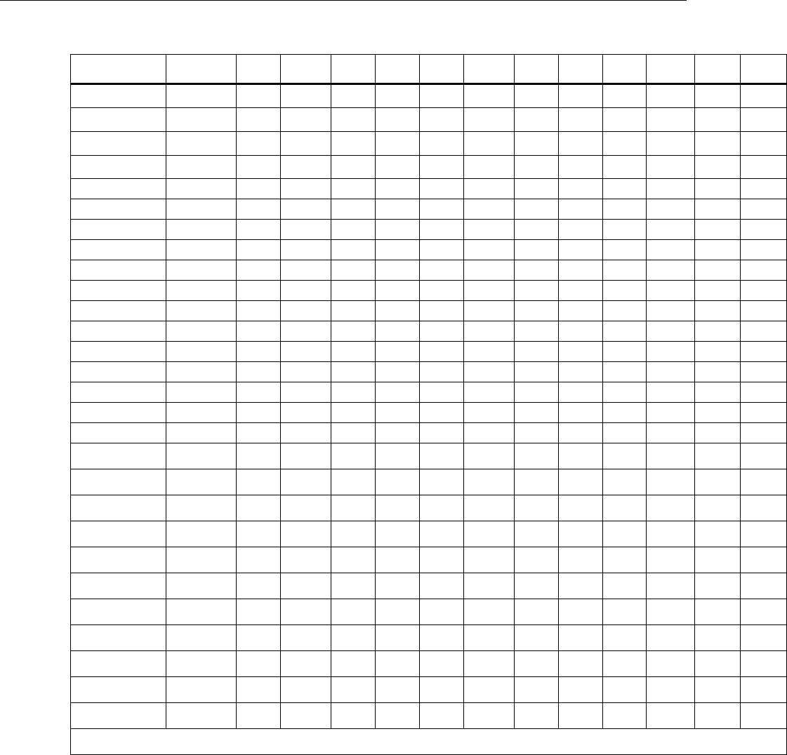
Ranges and Resolution
Model
Number
700G01 700G02 700G04 700G05 700G06 700G27 700G07 700G08 700G10 700G29 700G30 700G31
Pressure Range
(psi) 0.4 1 15 30 100 300 500 1000 2000 3000 5000 10000
Vacuum Range
(psi) -0.4 -1 -14 -14 -12 -12 -12 -14 -14 -14 -14 -14
Burst Pressure
(psi) 3 5 60 120 400 1200 2000 4000 8000 10000 15000 20000
Proof Pressure
(psi) 1 3 30 60 200 600 1000 2000 4000 6000 10000 15000
Engineering Unit Factor
psi 1.0000 0.4000 1.0000 15.000 30.000 100.00 300.00 500.00 1000.0 2000.0 3000.0 5000.0 10000
bar 0.06894757 0.0276 0.0689 1.0342 2.0684 6.8948 20.684 34.474 68.948 137.90 206.84 344.74 689.48
mbar 68.94757 27.579 68.948 1034.2 2068.4 6894.8 20684 34474 68948 * * * *
kPa 6.894757 2.7579 6.8948 103.42 206.84 689.48 2068.4 3447.4 6894.8 13790 20684 34474 68948
MPa 0.006894757 0.0028 0.0069 0.1034 0.2068 0.6895 2.0684 3.4474 6.8948 13.790 20.684 34.474 68.948
kg/cm2 0.07030697 0.0281 0.0703 1.0546 2.1092 7.0307 21.092 35.153 70.307 140.61 210.92 351.53 703.07
mmHg @ 0°C 51.71507 20.686 51.715 775.73 1551.5 5171.5 15515 25858 51715 * * * *
inHg @ 0°C 2.03603 0.8144 2.0360 30.540 61.081 203.60 610.81 1018.0 2036.0 4072.1 6108.1 10180 20360
cmH2O @ 4°C 70.3089 28.124 70.309 1054.6 2109.3 7030.9 21093 35154 70309 * * * *
cmH2O @ 20°C 70.4336 28.173 70.434 1056.5 2113.0 7043.4 21130 35217 70434 * * * *
mmH2O @ 4°C 703.089 281.24 703.09 10546 21093 70309 * * * * * * *
mmH2O @ 20°C 704.336 281.73 704.34 10565 21130 70434 * * * * * * *
mH2O @ 4°C 0.703089 0.2812 0.7031 10.546 21.093 70.309 210.93 351.54 703.09 1406.2 2109.3 3515.4 7030.9
mH2O @ 20°C 0.704336 0.2817 0.7043 10.565 21.130 70.434 211.30 352.17 704.34 1408.7 2113.0 3521.7 7043.4
inH2O @ 4°C 27.68067 11.072 27.681 415.21 830.42 2768.1 8304.2 13840 27681 55361 83042 * *
inH2O @ 20°C 27.72977 11.092 27.730 415.95 831.89 2773.0 8318.9 13865 27730 55460 83189 * *
inH2O @ 60°F 27.70759 11.083 27.708 415.61 831.23 2770.8 8312.3 13854 27708 55415 83123 * *
ftH2O @ 4°C 2.306726 0.9227 2.3067 34.601 69.202 230.67 692.02 1153.4 2306.7 4613.5 6920.2 11534 23067
ftH2O @ 20°C 2.310814 0.9243 2.3108 34.662 69.324 231.08 693.24 1155.4 2310.8 4621.6 6932.4 11554 23108
ftH2O @ 60°F 2.308966 0.9236 2.3090 34.634 69.269 230.90 692.69 1154.5 2309.0 4617.9 6926.9 11545 23090
ft Sea Water 2.24719101 0.8989 2.2472 33.708 67.416 224.72 674.16 1123.6 2247.2 4494.4 6741.6 11236 22472
m Sea Water 0.68494382 0.2740 0.6849 10.274 20.548 68.494 205.48 342.47 684.94 1369.9 2054.8 3424.7 6849.4
Torr 51.71507 20.686 51.715 775.73 1551.5 5171.5 15515 25858 51715 * * * *
* - range will not be displayed due to limitations on display resolution. In all cases, resolution is limited to 100,000 counts.
Pressure Gauge
Maintenance
7
Model Number 700GA4 700GA5 700GA6 700GA27 700RG05 700RG06 700RG07 700RG08 700RG29 700RG30 700RG31
Pressure Range
(psi) 15 psia 30 psia 100 psia 300 psia 30 100 500 1000 3000 5000 10000
Vacuum Range
(psi) 0 psia 0 psia 0 psia 0 psia -14 -12 -12 -14 -14 -14 -14
Burst Pressure
(psi) 60 120 400 1200 90 400 2000 4000 10000 15000 20000
Proof Pressure
(psi) 30 60 200 600 60 200 1000 2000 6000 10000 15000
Engineering Unit Factor
psi 1.0000 15.000 30.000 100.00 300.00 30.000 100.000 500.00 1000.00 3000.0 5000.0 10000.0
bar 0.06894757 1.0342 2.0684 6.8948 20.684 2.0684 6.8948 34.474 68.948 206.84 344.74 689.48
mbar 68.94757 1034.2 2068.4 6894.8 20684 2068.4 6894.8 34474 68948 * * *
kPa 6.894757 103.42 206.84 689.48 2068.4 206.84 689.48 3447.4 6894.8 20684 34474 68948
MPa 0.006894757 0.1034 0.2068 0.6895 2.0684 0.2068 0.6895 3.4474 6.8948 20.684 34.474 68.948
kg/cm2 0.07030697 1.0546 2.1092 7.0307 21.092 2.1092 7.0307 35.153 70.307 210.92 351.53 703.07
mmHg @ 0°C 51.71507 775.73 1551.5 5171.5 15515 1551.5 5171.5 25858 51715 * * *
inHg @ 0°C 2.03603 30.540 61.081 203.60 610.81 61.081 203.60 1018.0 2036.0 6108.1 10180 20360
cmH2O @ 4°C 70.3089 1054.6 2109.3 7030.9 21093 2109.3 7030.9 35154 70309 * * *
cmH2O @ 20°C 70.4336 1056.5 2113.0 7043.4 21130 2113.0 7043.4 35217 70434 * * *
mmH2O @ 4°C 703.089 10546 21093 70309 * 21093 70309 * * * * *
mmH2O @ 20°C 704.336 10565 21130 70434 * 21130 70434 * * * * *
mH2O @ 4°C 0.703089 10.546 21.093 70.309 210.93 21.093 70.309 351.54 703.09 2109.3 3515.4 7030.9
mH2O @ 20°C 0.704336 10.565 21.130 70.434 211.30 21.130 70.434 352.17 704.34 2113.0 3521.7 7043.4
inH2O @ 4°C 27.68067 415.21 830.42 2768.1 8304.2 830.42 2768.1 13840 27681 83042 * *
inH2O @ 20°C 27.72977 415.95 831.89 2773.0 8318.9 831.89 2773.0 13865 27730 83189 * *
inH2O @ 60°F 27.70759 415.61 831.23 2770.8 8312.3 831.23 2770.8 13854 27708 83123 * *
ftH2O @ 4°C 2.306726 34.601 69.202 230.67 692.02 69.202 230.67 1153.4 2306.7 6920.2 11534 23067
ftH2O @ 20°C 2.310814 34.662 69.324 231.08 693.24 69.324 231.08 1155.4 2310.8 6932.4 11554 23108
ftH2O @ 60°F 2.308966 34.634 69.269 230.90 692.69 69.269 230.90 1154.5 2309.0 6926.9 11545 23090
ft Sea Water 2.24719101 33.708 67.416 224.72 674.16 67.416 224.72 1123.6 2247.2 6741.6 11236 22472
m Sea Water 0.68494382 10.274 20.548 68.494 205.48 20.548 68.494 342.47 684.94 2054.8 3424.7 6849.4
Torr 51.71507 775.73 1551.5 5171.5 15515 1551.5 5171.5 25858 51715 * * *
* - range will not be displayed due to limitations on display resolution. In all cases, resolution is limited to 100,000 counts.
Maintenance
How to Clean the Product
Clean the Product with a soft cloth dampened with water or water and weak soap.
Caution
To prevent possible damage to the Product, do not use
solvents or abrasive cleansers.
Caution
For safe operation and maintenance of the product:
• Repair the Product before use if the battery leaks.
• Remove batteries to prevent battery leakage and damage to the
Product if it is not used for an extended period.
• Be sure that the battery polarity is correct to prevent battery
leakage.
• Have an approved technician repair the Product.
700G Series
Calibration Manual
8
How to Change the Batteries
Warning
To prevent possible electrical shock, fire, or personal injury,
batteries must only be changed in an area known to be non-
hazardous. Explosion hazard.
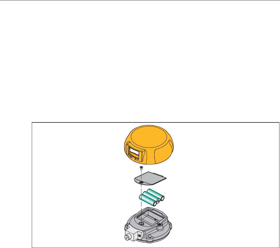
To change the batteries, see Figure 1:
1. Remove the Product holster.
2. Use a Phillips screwdriver to loosen the captive screw on the battery door.
3. Remove the battery door.
4. Replace the three AA batteries.
5. Install the battery door again.
6. Tighten the captive screw.
7. Put the Product back into the holster.
+
-
-
gvv002.eps
Figure 1. How to Change the Batteries
Pressure Gauge
Performance Verification Tests
9
Performance Verification Tests
Fluke recommends certification each year. To re-certify, do the verification procedure. If
test points are out of tolerance, calibrate the Product and then re-verify. Use the
subsequent tests to make sure that the Product is in its specification limits.
Required Equipment
The equipment necessary for verification of the Product is shown in Table 2. If these
instruments are not available, you can replace them with other instruments that have the
same minimal specification requirements.
Table 2. Equipment Required for Verification
Equipment Minimum Specification Recommended Model
Dead Weight Tester 300 to 10,000 psig
Accuracy: 0.01 % of Reading Pressurement P3000, P3100
Low Pressure
Controller/Calibrator
100 inH2O
Accuracy: 0.02 % of Range Ruska 7250LP
Absolute Pressure
Controller/Calibrator
300 psia
Accuracy: 0.01 % of Reading Ruska 7250xi
How to Verify Pressure
For each procedure there is a table of test points and permitted Product indications. If the
result of the test is not in the range shown, the Unit Under Test (UUT) is out of tolerance
and must be calibrated or repaired. For Product support, see the “How to Contact Fluke”
section. The 700G01 and 700G02 require a low-pressure standard such as the Ruska
7250LP. Because absolute pressure of deadweight can be complex, a
Controller/Calibrator is recommended for the 700GA Gauges.
Follow these general instructions for all the tests:
• Make sure the batteries are fully charged.
• Let the verification equipment warm-up for its specified time.
• For each test, make sure the verification equipment is stable and that the “unsettled”
annunciator on the UUT is not shown.
1. Carefully attach the pressure fitting of the pressure standard to the pressure port of
the UUT.
Note
Use plenty of PFTE tape when you attach the pressure fitting.
The display reads 0.00 PSI with the pressure standard opened to ambient air. If it does
not, push until the display shows 0.00 PSI.
2. Set up the pressure standard for the sequence of psi inputs from Table 3. These inputs
will be put into the pressure port of the UUT.
3. Make sure the pressure has become stable at each input before you verify the display
indication.
4. Apply the inputs from Table 3.
5. Carefully vent all pressure and disconnect the UUT from the pressure standard.
700G Series
Calibration Manual
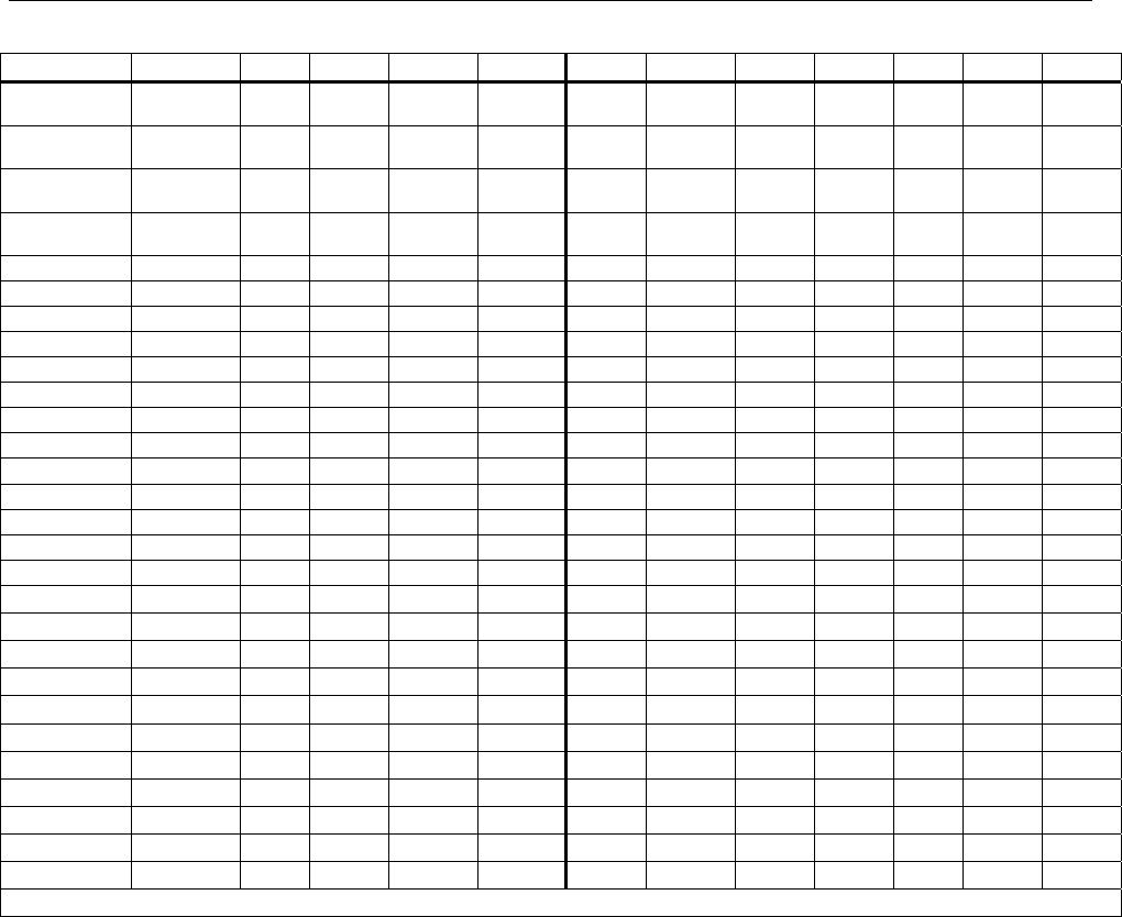
10
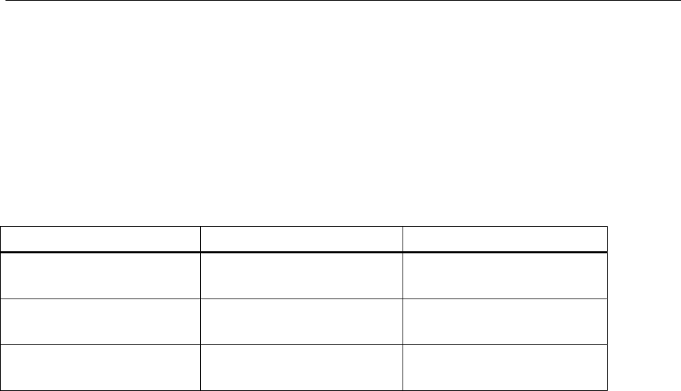
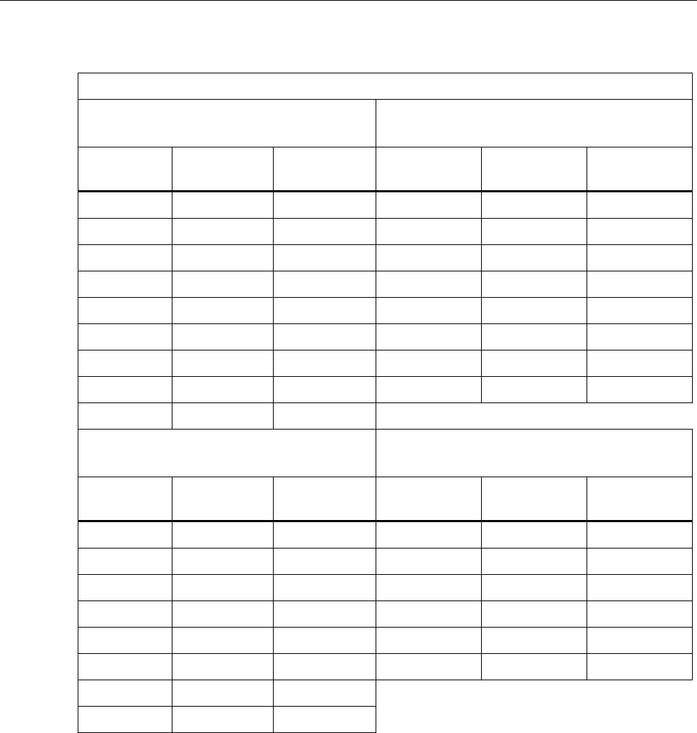
Table 3. Verification Points (In psi)
700G01
0.4 psi
700G02
1 psi
Input
Pressure
Lower
Limit
Upper
Limit
Input
Pressure Lower Limit Upper Limit
0.3600 0.3604 0.3596 1.0000 1.0010 0.9990
0.3300 0.3304 0.3296 0.9000 0.9010 0.8990
0.2500 0.2504 0.2496 0.7000 0.7010 0.6990
0.1700 0.1704 0.1696 0.5000 0.5010 0.4990
0.0900 0.0904 0.0896 0.3000 0.3010 0.2990
0.0300 0.0304 0.0296 0.1000 0.1010 0.0990
0.0000 0.0004 -0.0004 0.0000 0.0010 -0.0010
-0.0600 -0.0596 -0.0604 -0.1000 -0.0990 -0.1010
-0.1400 -0.1396 -0.1404 -0.3000 -0.2990 -0.3010
-0.2300 -0.2296 -0.2304 -0.6000 -0.5990 -0.6010
-0.3000 -0.2996 -0.3004 -0.8000 -0.7990 -0.8010
-0.3600 -0.3596 -0.3604 -1.0000 -0.9990 -1.0010
700G04
15 psi
700G05
30 psi
Input
Pressure
Lower
Limit
Upper
Limit
Input
Pressure Lower Limit Upper Limit
15.000 14.993 15.008 30.000 29.985 30.015
14.000 13.993 14.008 28.125 28.110 28.140
12.000 11.993 12.008 24.000 23.985 24.015
9.750 9.743 9.758 19.500 19.485 19.515
7.500 7.493 7.508 15.250 15.235 15.265
5.500 5.493 5.508 11.000 10.985 11.015
3.250 3.243 3.258 6.750 6.735 6.765
1.250 1.243 1.258 2.500 2.485 2.515
0.000 -0.008 0.008 0.000 -0.015 0.015
-5.000 -5.015 -4.985 -5.000 -5.030 -4.970
-10.000 -10.015 -9.985 -10.000 -10.030 -9.970
-14.000* -14.015 -13.985 -14.000* -14.030 -13.970
Pressure Gauge
Performance Verification Tests
11
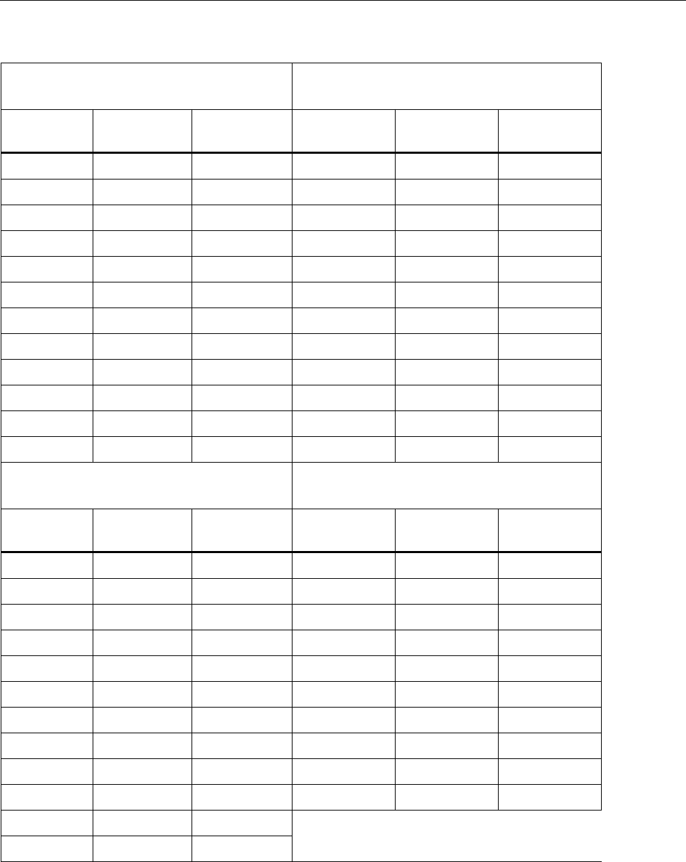
Table 3. Verification Points (In psi) (cont.)
700G06
100 psi
700G27
300 psi
Input
Pressure
Lower
Limit
Upper
Limit
Input
Pressure Lower Limit Upper Limit
100.00 99.95 100.05 300.00 299.85 300.15
93.75 93.70 93.80 281.25 281.10 281.40
81.25 81.20 81.30 243.75 243.60 243.90
68.75 68.70 68.80 206.25 206.10 206.40
56.25 56.20 56.30 168.75 168.60 168.90
43.75 43.70 43.80 131.25 131.10 131.40
31.25 31.20 31.30 93.75 93.60 93.90
18.75 18.70 18.80 56.25 56.10 56.40
6.25 6.20 6.30 18.75 18.60 18.90
0.00 -0.05 0.05 0.00 -0.15 0.15
-6.00 -6.10 -5.90 -6.00 -6.30 -5.70
-12.00* -12.10 -11.90 -12.00* -12.30 -11.70
700G07
500 psi
700G08
1000 psi
Input
Pressure
Lower
Limit
Upper
Limit
Input
Pressure Lower Limit Upper Limit
500.00 499.75 500.25 1000.0 999.5 1000.5
468.75 468.50 469.00 937.5 937.0 938.0
406.25 406.00 406.50 812.5 812.0 813.0
343.75 343.50 344.00 687.5 687.0 688.0
281.25 281.00 281.50 562.5 562.0 563.0
218.75 218.50 219.00 437.5 437.0 438.0
156.25 156.00 156.50 312.5 312.0 313.0
93.75 93.50 94.00 187.5 187.0 188.0
31.25 31.00 31.50 62.5 62.0 63.0
0.00 -0.25 0.25 0.0 -0.5 0.5
-6.00 -6.50 -5.50
-12.00* -12.50 -11.50
700G Series
Calibration Manual
12
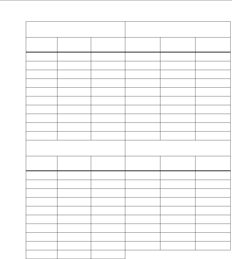
Table 3. Verification Points (In psi) (cont.)
700G10
2000 psi
700G29
3000 psi
Input
Pressure
Lower
Limit
Upper
Limit
Input
Pressure Lower Limit Upper Limit
2000.0 2001.0 1999.0 3000.0 2998.5 3001.5
1800.0 1801.0 1799.0 2812.5 2811.0 2814.0
1600.0 1601.0 1599.0 2437.5 2436.0 2439.0
1300.0 1301.0 1299.0 2062.5 2061.0 2064.0
1100.0 1101.0 1099.0 1687.5 1686.0 1689.0
900.0 901.0 899.0 1312.5 1311.0 1314.0
600.0 601.0 599.0 937.5 936.0 939.0
300.0 301.0 299.0 562.5 561.0 564.0
100.0 101.0 99.0 187.5 186.0 189.0
0.0 1.0 -1.0 0.0 -1.5 1.5
700G30
5000 psi
700G31
10000 psi
Input
Pressure
Lower
Limit
Upper
Limit
Input
Pressure Lower Limit Upper Limit
5000.0 4997.5 5002.5 10000 9995 10005
4687.5 4685.0 4690.0 9000 8995 9005
4062.5 4060.0 4065.0 7500 7495 7505
3437.5 3435.0 3440.0 6500 6495 6505
2812.5 2810.0 2815.0 5500 5495 5505
2187.5 2185.0 2190.0 4500 4495 4505
1562.5 1560.0 1565.0 1500 1495 1505
937.5 935.0 940.0 500 495 505
312.5 310.0 315.0 0. -5 5
0.0 -2.5 2.5

Pressure Gauge
Performance Verification Tests
13
Table 3. Verification Points (In psi) (cont.)
Absolute Gauges
700GA4
15 psia
700GA5
30 psia
Input
Pressure
Lower
Limit
Upper
Limit
Input
Pressure Lower Limit Upper Limit
15.000 15.008 14.992 30.000 30.015 29.985
14.000 14.008 13.992 28.000 28.015 27.985
12.500 12.508 12.492 25.000 25.015 24.985
10.000 10.008 9.992 20.000 20.015 19.985
8.000 8.008 7.992 16.500 16.515 16.485
6.500 6.508 6.492 13.000 13.015 12.985
4.500 4.508 4.492 9.000 9.015 8.985
3.000 3.008 2.992 6.000 6.015 5.985
1.000 1.008 0.992 2.000 2.015 1.985
0.350 0.358 0.342 0.350 0.365 0.335
700GA6
100 psia
700GA27
300 psia
Input
Pressure
Lower
Limit
Upper
Limit
Input
Pressure Lower Limit Upper Limit
100.00 100.05 99.95 300.00 300.15 299.85
93.00 93.05 92.95 281.00 281.15 280.85
81.00 81.05 80.95 243.00 243.15 242.85
68.00 68.05 67.95 206.00 206.15 205.85
56.00 56.05 55.95 168.00 168.15 167.85
43.00 43.05 42.95 131.00 131.15 130.85
31.00 31.05 30.95 93.00 93.15 92.85
18.00 18.05 17.95 56.00 56.15 55.85
6.00 6.05 5.95 18.00 18.15 17.85
0.50 0.55 0.45 5.00 5.15 4.85
0.50 0.65 0.35
700G Series
Calibration Manual
14
Table 3. Verification Points (In psi) (cont.)
Reference Gauges
700RG5
30 psi
700RG6
100 psi
Input
Pressure
Lower
Limit
Upper
Limit
Input
Pressure Lower Limit Upper Limit
30.000 30.015 29.985 100.000 100.050 99.950
24.000 24.015 23.985 80.000 80.042 79.958
18.000 18.015 17.985 60.000 60.034 59.966
12.000 12.015 11.985 40.000 40.026 39.974
6.000 6.015 5.985 20.000 20.018 19.982
0.000 0.015 -0.015 0.000 0.010 -0.010
-5.000 -4.970 -5.030 -6.000 -5.900 -6.100
-10.000 -9.970 -10.030 -12.000* -11.900 -12.100
-14.000* -13.970 -14.030
700RG7
500 psi
700RG8
1000 psi
Input
Pressure
Lower
Limit
Upper
Limit
Input
Pressure Lower Limit Upper Limit
500.00 500.25 499.75 1000.00 1000.50 999.50
400.00 400.21 399.79 800.00 800.42 799.58
300.00 300.17 299.83 600.00 600.34 599.66
200.00 200.13 199.87 400.00 400.26 399.74
100.00 100.09 99.91 200.00 200.18 199.82
0.00 0.05 -0.05 0.00 0.10 -0.10
-6.00 -5.50 -6.50
-12.00* -11.50 -12.50
Pressure Gauge
Performance Verification Tests
15
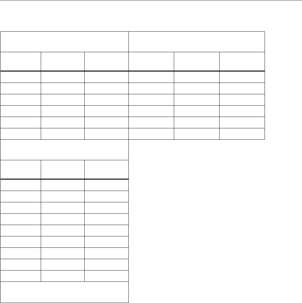
Table 3. Verification Points (In psi) (cont.)
700RG29
3000 psi
700RG30
5000 psi
Input
Pressure
Lower
Limit
Upper
Limit
Input
Pressure Lower Limit Upper Limit
3000.0 3001.5 2998.5 5000.0 5002.5 4997.5
2400.0 2401.3 2398.7 4000.0 4002.1 3997.9
1800.0 1801.0 1799.0 3000.0 3001.7 2998.3
1200.0 1200.8 1199.2 2000.0 2001.3 1999.1
600.0 600.5 599.5 1000.0 1000.9 999.1
0.0 0.3 -0.3 0.0 0.5 -0.5
700RG31
10000 psi
Input
Pressure
Lower
Limit
Upper
Limit
10000.0 10005.0 9995.0
9000.0 9004.6 8995.4
7500.0 7504.0 7496.0
6500.0 6503.6 6496.4
5500.0 5503.2 5496.8
4500.0 4502.8 4497.2
1500.0 1501.6 1498.4
500.0 501.2 498.8
0.0 1.0 -1.0
*At altitudes -14 psi or -12 psi may not be
possible. Replace with a local near-vacuum
point when necessary.
700G Series
Calibration Manual
16
Calibration Adjustment
Calibration adjustment is done electronically by internal software with the Product case
closed. The recommended adjustment procedure is a 2-point adjust that adjusts a low and
high point. This adjustment can be applied to any of the 700 family of gauges. It is the
only adjustment that may used with a 700RG ranges.
Note
This is an ambient temperature calibration, and must be done at an ambient
temperature of 23 °C ± 3 °C (72 °F ± 5 °F). Calibration out of this
temperature range voids the temperature compensation software in the
Product.
Test Equipment
For verification and calibration adjustment, pressure and/or vacuum standards that can
make and show pressures from vacuum to the full-scale range of the UUT are necessary.
A TUR standard of 4:1 or better is necessary to keep the Product at its specified accuracy.
Connections
The Product uses a ¼ inch NPT male connection in the pressure input port. Different
adapters can be necessary to connect to the pressure standard. Always make sure the
hose, tubing, and fittings. Have a rated working pressure at or above the pressure of the
unit. It is also important that there be no leaks when you calibrate the Product. Use Teflon
tape where necessary.
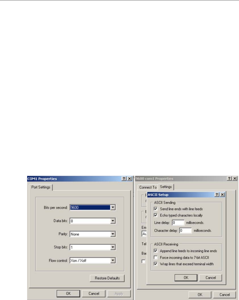
Enter 2-Point Adjust Mode
Follow the instructions for serial interface setup in the next section. Figure 2 can be used
to guide setup if HyperTerminal will be used.
ht.bmp
Figure 2. Calibration Setup with HyperTerminal

Pressure Gauge
Calibration Adjustment
17
1. Connect the PC to the Product with the interface cable that comes with
700G/TRACK software.
2. After all connections have been made, vent the Product to atmosphere and send this
command: OFFSET_ADJ?
3. Note the value returned.
4. For absolute units, apply a vacuum of <0.35 psiA, the applied vacuum should be used
for N in the OFFSET ADJUST command.
5. When the pressure is stable, send OFFSET_ADJ N, where N is the pressure given
from the OFFSET_ADJ? command.
6. Send the GAIN_ADJ? command.
7. Note the value returned.
8. Use an appropriate pressure standard to input a value equal or close to the noted
value. When the pressure is stable send, GAIN_ADJ N, where N is the entered
pressure.
9. Reset the power with the power button to save the calibration.
Two-point calibration is complete. Full adjustment may be used when the Product errors
are not linear.
Full Adjust
Caution
To avoid loss of data, do not use this procedure on a 700RG
gauge. To do this would over write the characterized values that
make it a reference gauge.
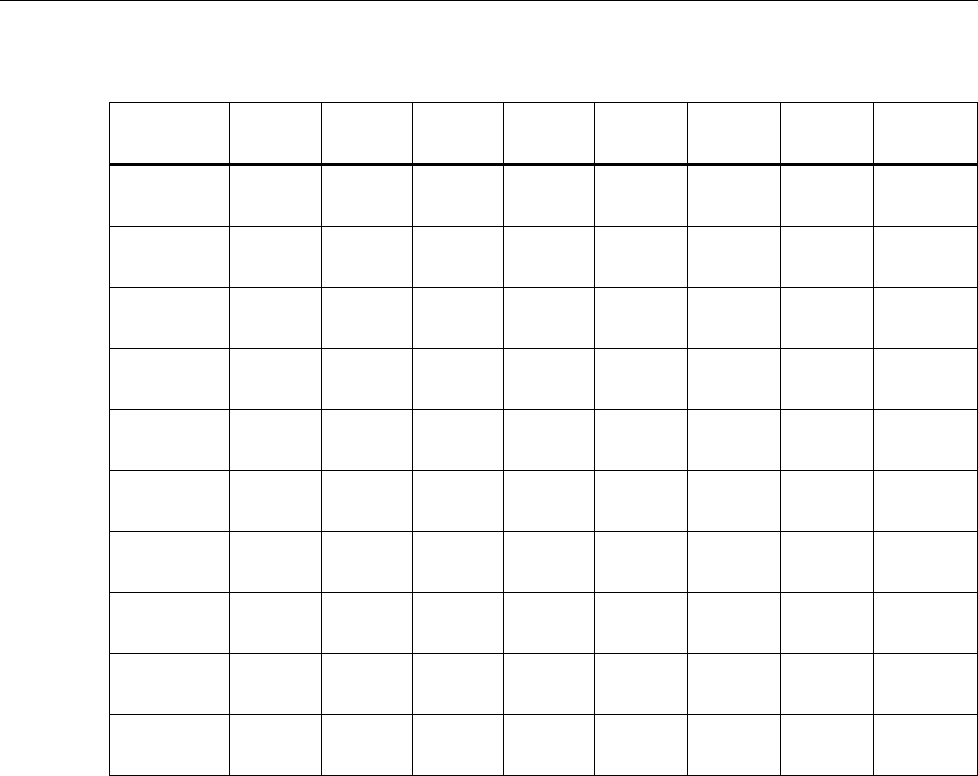
All calibration commands and adjustments are done with the keypad. Eight calibration
points are used in the adjustment. They go from full-scale to zero at pressures that equal
100 %, 87.5 %, 75 %, 62.5 %, 50 %, 37.5 %, 25 %, 12.5 %, and 0 % of full scale plus
vacuum.
After you have made the connections, turn on the power while you hold . Use and
to enter the password: 101 then push . If you went into calibration mode
correctly, the display will show CAL. The pressure value shown will be the full-scale
value of the Product. For Calibration points and their values, see Table 4.
Procedure Example
Note
This example uses a 700G07 Pressure Gauge (maximum pressure
500.00 psi). Apply the shown pressures necessary for your Product as
shown in Table 4 .
The Product will prompt you for the necessary pressure at each calibration point.
1. Use the pressure standard to output 500.00 psi (100 %). After the output is stable,
push to continue. As the Product measures, the screen will show ———-. When
measurements are complete the screen will show the calibration value.
2. Use the pressure standard to output 437.50 psi (87.5 %). After the output is stable,
push to continue. As the Product measures, the screen will show ———-. When
measurements are complete the screen will show the calibration value.
3. Use the Pressure Standard to output 375.00 psi (75 %). After the output is stable,

700G Series
Calibration Manual
18
push to continue. As the Product measures, the screen will show ———-. When
measurements are complete the screen will show the calibration value.
4. Use the Pressure Standard to output 312.50 psi (62.5 %). After the output is stable,
push to continue. As the Product measures, the screen will show ———-. When
measurements are complete the screen will show the calibration value.
5. Use the Pressure Standard to output 250.00 psi (50 %). After the output is stable,
push to continue. As the Product measures, the screen will show ———-. When
measurements are complete the screen will show the calibration value.
6. Use the Pressure Standard to output 187.50 psi (37.5 %). After the output is stable,
push to continue. As the Product measures, the screen will show ———-. When
measurements are complete the screen will show the calibration value.
7. Use the Pressure Standard to output 125.00 psi (25 %). After the output is stable,
push to continue. As the Product measures, the screen will show ———-. When
measurements are complete the screen will show the calibration value.
8. Use the Pressure Standard to output 62.50 psi (12.5 %). After the output is stable,
push to continue. As the Product measures, the screen will show ———-. When
measurements are complete the screen will show the calibration value.
9. Use the Pressure Standard to output 0.00 psi. After the output is stable, push to
continue. As the Product measures, the screen will show ———-. When
measurements are complete the screen will show the calibration value.
Note
Only some ranges use vacuum calibration. If your Product does not,
then this step can be skipped and calibration is complete.
10. Use the Pressure Standard to output -12.00 psi. After the output is stable, push to
continue. As the Product measures, the screen will show ———-. When the
measurements are complete, a Product reset occurs and the Product turns off then
turns on as usual.

Pressure Gauge
Calibration Adjustment
19
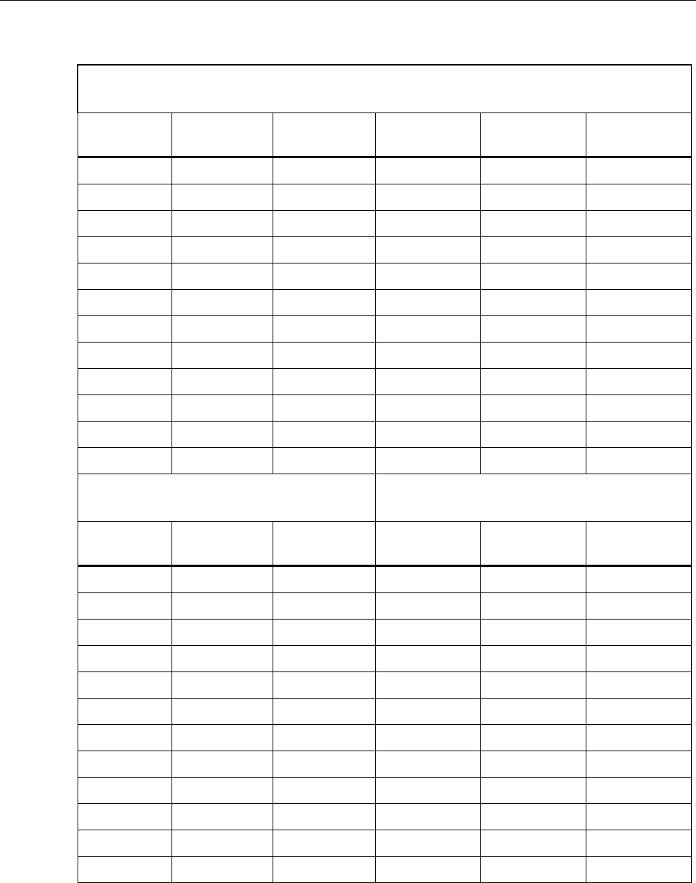
Table 4. Calibration Points
Model
Number 700G01 700G02 700G04 700G05 700G05 700G27 700G07 700G08
Pressure
Range (psi) 0.4 1 15 30 100 300 500 1000
Calibration
Point 1 0.3600 1.0000 15.000 30.000 100.00 300.00 500.00 1000.0
Calibration
Point 2 0.2880 0.8000 13.000 25.500 87.50 262.50 437.50 875.0
Calibration
Point 3 0.2080 0.6000 10.750 21.500 75.00 225.00 375.00 750.0
Calibration
Point 4 0.1280 0.4000 8.500 17.000 62.50 187.50 312.50 625.0
Calibration
Point 5 0.0480 0.2000 6.500 12.750 50.00 150.00 250.00 500.0
Calibration
Point 6 0.0000 0.0000 4.300 8.500 37.50 112.50 187.50 375.0
Calibration
Point 7 -0.0900 -0.2500 2.150 4.250 25.00 75.00 125.00 250.0
Calibration
Point 8 -0.1800 -0.5000 0.000 0.000 12.50 37.50 62.50 125.0
Calibration
Point 9 -0.2700 -0.7500 -7.000 -7.000 0.00 0.00 0.00 0.0
Calibration
Point 10 -0.3600 -1.0000 -14.000 -14.000 -12.00 -12.00 -12.00 -12.0
Calibration
Point 11
Model
Number 700G10 700G29 700G30 700G31 700GA4 700GA5 700GA6 700GA27
Pressure
Range (psi) 2000 3000 5000 10000 15 psia 30 psia 100 psia 300 psia
Calibration
Point 1 2000.0 3000.0 5000.0 10000 15.000 30.000 100.00 300.00
700G Series
Calibration Manual
20
Table 4. Calibration Points (Cont.)
Model
Number 700G10 700G29 700G30 700G31 700GA4 700GA5 700GA6 700GA27
Calibration
Point 2 1750.0 2625.0 4375.0 9300 13.125 26.250 87.50 262.50
Calibration
Point 3 1500.0 2250.0 3750.0 8000 11.000 22.500 75.00 225.00
Calibration
Point 4 1250.0 1875.0 3125.0 6500 25.000 18.750 62.50 187.50
Calibration
Point 5 1000.0 1500.0 2500.0 5000 9.375 15.000 50.00 150.00
Calibration
Point 6 750.0 1125.0 1875.0 3900 7.500 11.250 37.50 112.50
Calibration
Point 7 500.0 750.0 1250.0 2800 5.625 7.500 25.00 75.00
Calibration
Point 8 250.0 375.0 625.0 1800 3.750 3.750 12.50 37.50
Calibration
Point 9 0.0 0.0 0.0 1000 1.875 0.300 0.40 0.50
Calibration
Point 10 500 0.300
Calibration
Point 11 0
Serial Interface
Use terminal communication software on a PC to set up terminal communication. An
RS-232 to USB cable is necessary. This cable comes with 700G/TRACK Software.
Use these terminal parameters:
• Bits per second: 9600
• Data bits: 8
• Parity: None
• Stop bits: 1
• Flow control: None
• Local echo: on

Pressure Gauge
Serial Interface
21
List of Commands
Table 5 shows the commands that the Product uses to communicate. Send these
commands from the PC to set up the Product or to take a measurement.
Table 5. Commands
Command Description
CAL_START Puts the calibrator in calibration mode
*CLS Deletes the error queue
FAULT? Shows an error code from the error queue
*IDN? Identification query. Shows the manufacturer, model number, and firmware
revision level of the calibrator
TARE Tares the offset pressure of the measurement on the calibrator
TARE? Shows the current tare value
PRES_UNIT? Shows the pressure unit for the upper display
PRES_UNIT Sets the pressure unit for the display
ZERO_MEAS Zeros the pressure of the calibrator
ZERO_MEAS? Shows the current zero offset value
MINMAX_RST Resets the minimum and maximum recorded values
MIN? Shows the minimum recorded value
MAX? Shows the maximum recorded value
HC_OFF Turns off the Product
HC_DFLT Sets auto-off defaults
TEMP? Shows temperature in the units that you choose
HC_COMP_OFF Turns off temperature compensation
HC_COMP_ON Turns on temperature compensation
HC_COMP? Shows state of temperature compensation
HC_RD_2410? Shows 2410 ADC counts
HC_SI_OFF Turns off SI mode
HC_SI_ON Turns on SI mode
CAL_STORE Keeps calibration data
HC_AUTO_OFF Turns off auto shutdown
HC_AUTO_ON Turns on auto shutdown
CUST_MULT? Sets the multiplier for the custom unit type
STREAM_OFF Turns of streaming data
STREAM_ON Turns on streaming data
HC_TEMP? Same as TEMP?
VAL? Shows the measured pressure value in selected units
HC_CMD_LIST Prints a command list
TEMP_UNIT Set a temperature unit
TEMP_UNIT? Shows temperature unit

700G Series
Calibration Manual
22
Parameter Units
The Product can be set to show the measurement units in Table 6.
Table 6. Measurement Units Used with Serial Port Commands
Units Description
Psi Pressure in pounds per square-inch
Bar Pressure in bars
mBar Pressure in millibars
Kg/cm2 Pressure in kilograms per centimeter squared
inH2O4C Pressure in inches of water at 4 °C
inH2O20C Pressure in inches of water at 20 °C
inH2O60F Pressure in inches of water at 60 °F
mH2O4C Pressure in meters of water at 4 °C
mH2O20C Pressure in meters of water at 20 °C
cmH2O4C Pressure in centimeters of water at 4 °C
cmH2O4C Pressure in centimeters of water at 20 °C
mmH2O4C Pressure in millimeters of water at 4 °C
mmH2O20C Pressure in millimeters of water at 20 °C
MSW Pressure in meters of salt water
ftH2O4C Pressure in feet of water at 4 °C
ftH2O20C Pressure in feet of water at 20 °C
ftH2O60F Pressure in feet of water at 60 °F
FTSW Pressure in feet of salt water
inhg0C Pressure in inches of mercury at 0 °C
mmHg0C Pressure in millimeters of mercury at 0 °C
kPa Pressure in kilopascals
mPa Pressure in mega Pascal
Torr Pressure in Torr
CUST Pressure in custom-defined units
Far Temperature in Fahrenheit
Cel Temperature in Celsius
Pressure Gauge
23
Error Codes
A list of error codes are in Table 7.
Table 7. Error Codes
Error Description
101 A non-numeric entry was received where a numeric entry is necessary
102 Too many significant digits entered
103 Invalid units or parameter value received
105 Entry is above the upper limit of the allowable range
106 Entry is below the lower limit of the allowable range
108 A required command parameter was missing
109 An invalid pressure unit was received
117 An unknown command was received
120 The serial input buffer overflowed
121 Too many entries in the command line
122 Pressure module not connected
700G Series
Calibration Manual
24
Replacement Parts and Accessories
Table 8 lists the customer replaceable parts. Replacement parts can be ordered from
Fluke Corporation and its approved representatives. Use the part number when you order
the replacement part or accessory. See the “How to Contact Fluke” section.
Table 8. Replacement Parts and Accessories
Part
Number Description
4110667 Fluke-700G, Decal, Front
4110671 Fluke-700G, Decal, Back
4374013 Decal, Top Case Identification For 700G10 2000 psia
4374024 Decal,Top Case Identification For 700G01 10 IN/H2O
4374036 Decal, Top Case Identification For 700G02 30 IN/H2O
4374049 Decal,Top Case Identification For 700GA4 15 psia
4374051 Decal, Top Case Identification For 700GA5 30 psia
4374060 Decal, Top Case Identification For 700GA6 100 psia
4374072 Decal, Top Case Identification For 700GA27 300 psia
4374085 Decal, Top Case Identification For 700RG05 30 PSIG
4374097 Decal, Top Case Identification For 700RG06 100 PSIG
4374106 Decal, Top Case Identification For 700RG07 500 PSIG
4374114 Decal, Top Case Identification For 700RG08 1000 PSIG
4374123 Decal, Top Case Identification For 700RG29 3000 PSIG
4374138 Decal, Top Case Identification For 700RG30 5000 PSIG
4374145 Decal, Top Case Identification For 700RG31 10000 PSIG
4374161 Decal, Top Case Identification For 700G04 15 PSIG
4374177 Decal, Top Case Identification For 700G05 30 PSIG
4374189 Decal, Top Case Identification For 700G06 100 PSIG
4374192 Decal, Top Case Identification For 700G27 300 PSIG
4374200 Decal, Top Case Identification For 70G07 500 PSIG
4374217 Decal, Top Case Identification For 700G08 1000 PSIG
4374221 Decal, Top Case Identification For 700G29 3000 PSIG
4374239 Decal, Top Case Identification For 700G30 5000 PSIG
4374242 Decal, Top Case Identification For 700G31 10000 PSIG
4374256 Decal, Manifold Range 10in H20 27mbar
4374263 Decal, Manifold Range 30in H20 70mbar
Pressure Gauge
Replacement Parts and Accessories
25
Table 8. Replacement Parts and Accessories (cont.)
Part
Number Description
4374295 Decal, Manifold Range 150psi 10bar
4374301 Decal, Manifold Range 1500psi 100bar
4374312 Decal, Manifold Range 2000psi 140bar
4374320 Decal, Manifold Range 15psia 1bar
4374335 Decal, Manifold Range 30psia 2bar
4374347 Decal, Manifold Range 100psia 7bar
4374358 Decal, Manifold Range 300psia 20bar
4110680 Fluke-700G04,15 Psi, Manifold Decal
4110698 Fluke-700G05, 30 Psi, Manifold Decal
4110705 Fluke-700G06,100 Psi, Manifold Decal
4110710 Fluke-700G27, 300 Psi, Manifold Decal
4110722 Fluke-700G07, 500 Psi, Manifold Decal
4110731 Fluke-700G08, 1000 Psi, Manifold Decal
4110746 Fluke-700G29, 3000 Psi, Manifold Decal
4110754 Fluke-700G30, 5000 Psi, Manifold Decal
4110768 Fluke-700G31, 10000 Psi, Manifold Decal
4110779 Fluke-700G, Pressure Gauge, Boot
4123225 Fluke 700G/TRACK Software and Serial Cable
4098606 700G Safety Information (15 language)
4098593 700G CD-ROM (includes 15 language Users Manual)

700G Series
Calibration Manual
26
