Fluke 707Ex Application Note
2015-09-09
: Fluke Fluke-707Ex-Application-Note-808128 fluke-707ex-application-note-808128 fluke pdf
Open the PDF directly: View PDF ![]() .
.
Page Count: 2
Application Note
Tracking down problems within
a process loop can be a difficult
challenge in the best of environ-
ments. Doing so in an area that
has the potential for explosion
takes the degree of difficulty to
another level – one where the
technician needs proper training
and equipment. This article will
demonstrate the practical applica-
tion of loop calibrators designed
to troubleshoot process loops in
intrinsically safe environments.
What is “intrinsically
safe?”
Intrinsic safety is a protection
standard employed in potentially
explosive atmospheres. Devices
certified as “intrinsically safe”
are designed to be unable to
release sufficient energy, by
either thermal or electrical
means, to cause ignition of
flammable material (gas, dust/
particulates).
Intrinsically safe standards
apply to all equipment that can
create one or more of a range
of defined potential explosion
sources:
• Electrical sparks
• Electrical arcs
• Flames
• Hot surfaces
• Static electricity
• Electromagnetic radiation
• Chemical reactions
• Mechanical impact
• Mechanical friction
• Compression ignition
• Acoustic energy
• Ionizing radiation
Intrinsic safety is particularly
important for technicians
working in industries like petro-
chemical and pharmaceutical,
around bulk materials such as
grain, mining, or any environ-
ment where explosive gases are
present.
The importance of safety in
these environments can’t be
stressed enough. It takes a very
small amount of energy to cause
an ignition; e.g., a mixture of
hydrogen in air requires only
2O uJ of energy. The proper
practices and tools will minimize
the inherent risk involved in
working around these hazards.
Intrinsically safe loop
calibration
To conduct loop calibrations in
potentially explosive environ-
ments, you need a loop calibrator
that is certified as intrinsically
safe. Intrinsically safe loop cali-
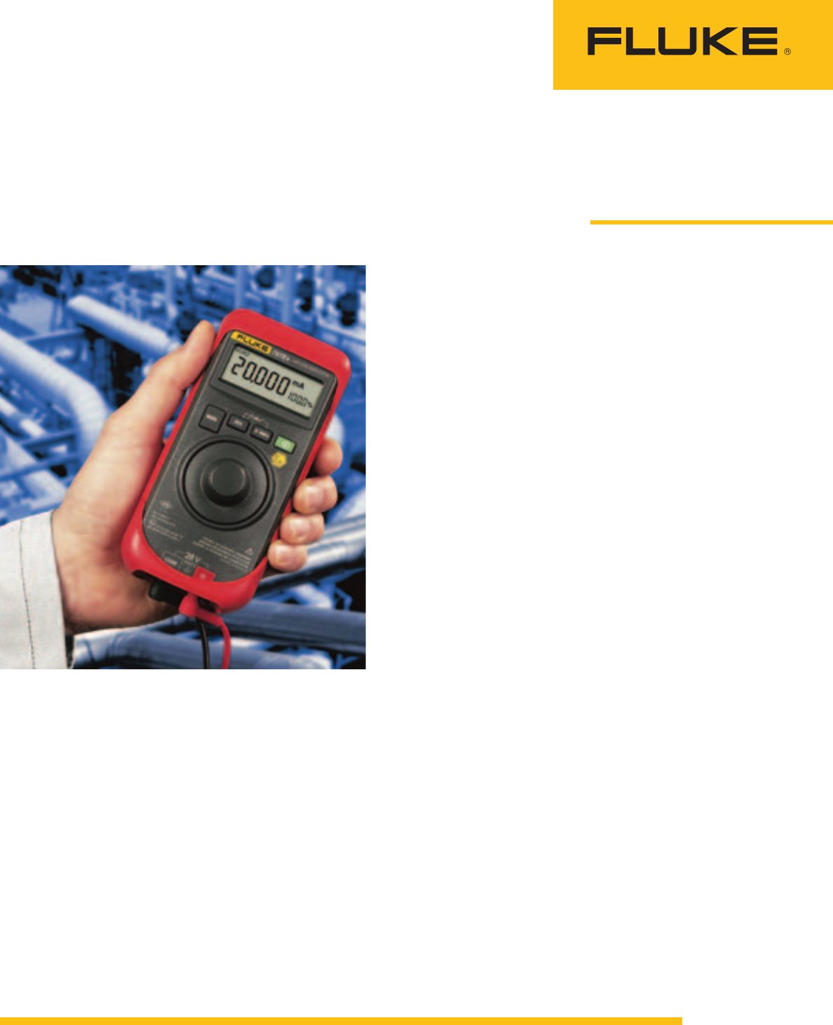
brators, such as the Fluke 707Ex,
must be certified in accordance
Troubleshooting process
loops in potentially
explosive atmospheres
From the Fluke Digital Library @ www.fluke.com/library
with the European ATEX (“Atmo-
sphères Explosibles,” French for
explosive atmospheres) directive
(Ex II 2 G Ex ia IIC T4) in Zones 1
and 2 for use in Europe and NEC
500; N.I. Class 1, Division 2 areas
Group A-D for use in the U.S.
In addition to an intrinsically
safe loop calibrator, strict adher-
ence to calibration procedures is
recommended, including:
Lock out: Make sure the system
is shut down and other work-
ers are notified that a potentially
dangerous operation will be tak-
ing place.
Tape off area: Tape the work
area off to prevent workers from
entering with potentially dan-
gerous electrical devices (cell
phones, handheld computers,
non-intrinsically safe tools).
Purge or vent the systems:
Safely purge or vent the system
to remove any gases that may
remain.
Use a gas detector: In an envi-
ronment where explosive gas
may be present, the use of a gas
detector is a prudent step before
starting a loop calibration. Gas
“sniffers” are available for a wide
variety of applications and from
handheld to larger, carted models.
Calibrate: Perform your calibra-
tion using an intrinsically safe
loop calibrator.
Clean up and reactivate: At the
conclusion of calibration, reverse
the process and reactivate the
system.
Loop calibration
The 707Ex Loop Calibrator has
the ability to replace the power
source in a current loop so you
can power and read a transmitter
at the same time without carry-
ing a digital multimeter (DMM).

2 Fluke Corporation Troubleshooting process loops in potentially explosive atmospheres
With the calibrator in control of
the current, you can accurately
set the current between 4 and
20 mA, controlling the loop and
the device connected to it. This
makes it possible to test valve
positioners (see below), mechani-
cal position indicators, flow
indicators and mA signal condi-
tioners.
For testing devices requir-
ing a voltage input, like a signal
conditioner or PLC, you can use
the source mode of a calibrator
in conjunction with a precision
resistor to generate accurate volt-
ages.
Simply taking a precision
resistor and placing it across the
output leads of a loop calibra-
tor creates a voltage across the
resistor that is directly controlled
by the source current from the
calibrator. For example, placing a
250 Ω resistor across the source
output jacks and driving it with a
4 to 20 mA current will produce
1 to 5 V across the resistor. Place
this voltage on the input of a sig-
nal conditioner and we have cre-
ated a test system to set linearity
as well as the zero and span
points of the conditioner. With a
DMM or ProcessMeter™ instru-
ment like the Fluke 789,
you can
measure the output of the signal
conditioner and ensure the proper
levels are coming out of the con-
ditioner with a corresponding
input voltage.
Testing valve positioners
Electronic valve positioners
should receive periodic in-field
calibrations as part of preventa-
tive maintenance programs. Fluke
loop calibrators are the ideal pro-
cess tool for these checks. Valve
positioners vary in design and
valve type and should be cali-
brated using specific instructions
from the individual manufacturer.
Quick operational checks
can be performed using a field
calibrator as a signal source
while observing the valve stem
position, mechanical position
indicators, or flow indicators as
input changes are made. Fluke
loop calibrators provide a conve-
nient source for simulating
the controller output to a valve
positioner.
The following example (using
a Fluke 707Ex calibrator) shows
a general method for an in-field
operational check of a valve fit-
ted with an electronic valve
positioner. These methods may
be adapted to various types of
valves, however manufacturer’s
specific instructions should
always be consulted for proper
and appropriate techniques. In
the following example, valve
operation and movement is
checked either by feel or by
observing valve stem movement.
Step 1: Basic set-up. Setting
the Fluke 707Ex Loop
Calibrator current output.
Place the calibrator in the 4-20
mA output current mode. Connect
the 707Ex to the input terminals
of the valve positioner.
Step 2: Zero adjustment
Set the 707Ex to an output of
4 mA and allow some time for
valve stem movement to stabilize.
Quickly decrease the current from
4 mA to 3.9 mA by depres-sing
and turning the vernier knob
in a counter-clockwise direc-
tion. You can operate the 707Ex
with one hand while feeling the
valve stem with your free hand
to check for any sign of move-
ment. Adjust for zero movement
between these two current set-
tings by using the Zero adjust-
ment on the positioner.
Increase and decrease current
from 4 mA to 4.1 mA using the
vernier knob in the depressed
position. Insure that the valve
stem just begins movement
above the 4.1 mA setting and
fully closed at 4 mA.
Step 3: Span (full open) posi-
tion check
Using the 25 % button, step the
valve input to 20 mA and allow
the valve to stabilize. Step the
input to 24 mA while watching
or feeling for movement of the
valve stem. Minimize this move-
ment using the Span adjustment
on the valve positioner.
Using the vernier knob in the
depressed position, adjust current
up and down between 20.10 mA
and 19.9 mA. There should be
no movement of the valve stem
above 20 mA and a slight move-
ment below 20 mA.
Step 4: Check zero and span
again
Many positioners have interactive
Zero and Span controls. This step
will help ensure proper valve
position adjustment.
Repeat Step 2 and Step 3.
Step 5: Linearity check
For valves with linear action, lin-
earity can be checked by setting
the 707Ex to 4 mA and stepping
current to 12 mA (50 %) while
observing valve travel. If your
valve is of a nonlinear type, refer
to the valve manual for proper
operational checks.
Step 6: Stroking the valve
Checking for smooth valve opera-
tion is easy to accomplish using
the Slow Ramp function of the
707Ex.
• Set the calibrator to mA source
mode and select the Slow
Ramp function ( ) by depress-
ing the 25 % and 0-100 %
buttons simultaneously.
• Allow the calibrator to ramp
through several cycles while
watching or feeling for any
abnormal operation of the
valve such as sticking in one
position momentarily or erratic
movement.
Summary
Calibrating process loops is an
essential part of regular plant
maintenance made all the more
difficult in potentially explosive
environments. Using intrinsically
safe tools and the proper proce-
dures to safeguard the working
area minimizes the risks involved.
Fluke Corporation
PO Box 9090, Everett, WA 98206 U.S.A.
Fluke Europe B.V.
PO Box 1186, 5602 BD
Eindhoven, The Netherlands
For more information call:
In the U.S.A. (800) 443-5853 or
Fax (425) 446-5116
In Europe/M-East/Africa +31 (0) 40 2675 200 or
Fax +31 (0) 40 2675 222
In Canada (800)-36-FLUKE or
Fax (905) 890-6866
From other countries +1 (425) 446-5500 or
Fax +1 (425) 446-5116
Web access: http://www.fluke.com
©2003-2010 Fluke Corporation.
Specifications subject to change without notice.
Printed in U.S.A. 7/2010 2098403B A-EN-N
Modification of this document is not permitted
without written permission from Fluke Corporation.
Fluke. Keeping your world
up and running.®
