Fluke 719Pro Users Manual
The-Fluke-719Pro-Electric-Pressure-Calibrator-User-Manual-Brochure The-Fluke-719Pro-Electric-Pressure-Calibrator-User-Manual-Brochure
Fluke-719Pro-150G-Electric-Pressure-Calibrator-User-Manual-Brochure Fluke-719Pro-150G-Electric-Pressure-Calibrator-User-Manual-Brochure
The-Fluke-719Pro-300G-Electric-Pressure-Calibrator-User-Manual-Brochure The-Fluke-719Pro-300G-Electric-Pressure-Calibrator-User-Manual-Brochure
2015-09-09
: Fluke Fluke-719Pro-Users-Manual-806739 fluke-719pro-users-manual-806739 fluke pdf
Open the PDF directly: View PDF ![]() .
.
Page Count: 80
- 719PRO Users Manual
- Introduction
- Contact Fluke
- Safety Information
- Symbols
- Standard Equipment
- Product Features
- Initial Setup and Basic Pressure Generation
- Electric Pump Considerations
- Measure Pressure
- Measure and Generate Current (4 mA to 20 mA)
- Measure Voltage
- Measure Temperature with an RTD
- Pressure Switch Test
- Transmitter Calibration
- Minimum and Maximum Storage Capability
- Factory Setups
- Custody Transfer / Flow Calibration
- Remote Operation
- Ranges and Resolution
- Maintenance
- User-Replaceable Parts and Accessories
- Specifications

October 2013
© 2013 Fluke Corporation. All rights reserved. Specifications are subject to change without notice.
All product names are trademarks of their respective companies.
719PRO
Pressure Calibrator
Users Manual
LIMITED WARRANTY AND LIMITATION OF LIABILITY
This Fluke product will be free from defects in material and workmanship for three years from the date of purchase. This
warranty does not cover fuses, disposable batteries, or damage from accident, neglect, misuse, alteration, contamination, or
abnormal conditions of operation or handling. Resellers are not authorized to extend any other warranty on Fluke’s behalf.
To obtain service during the warranty period, contact your nearest Fluke authorized service center to obtain return
authorization information, then send the product to that Service Center with a description of the problem.
THIS WARRANTY IS YOUR ONLY REMEDY. NO OTHER WARRANTIES, SUCH AS FITNESS FOR A PARTICULAR
PURPOSE, ARE EXPRESSED OR IMPLIED. FLUKE IS NOT LIABLE FOR ANY SPECIAL, INDIRECT, INCIDENTAL OR
CONSEQUENTIAL DAMAGES OR LOSSES, ARISING FROM ANY CAUSE OR THEORY. Since some states or countries
do not allow the exclusion or limitation of an implied warranty or of incidental or consequential damages, this limitation of
liability may not apply to you.
Fluke Corporation
P.O. Box 9090
Everett, WA 98206-9090
U.S.A.
Fluke Eu
r
ope B.V.
P.O. Box 1186
5602 BD Eindhoven
The Netherlands
11/99
i
Table of Contents
Title Page
Introduction .................................................................................................................... 1
Contact Fluke ................................................................................................................. 1
Safety Information .......................................................................................................... 2
Symbols ......................................................................................................................... 4
Standard Equipment....................................................................................................... 5
Product Features ............................................................................................................ 5
Display ....................................................................................................................... 8
Language Selection ................................................................................................... 9
Home Menu Functionality .......................................................................................... 10
Backlight Use ............................................................................................................ 10
The MENU Option ..................................................................................................... 10
Main Menu Functionality ............................................................................................ 11
Set the Active Display ........................................................................................... 11
Set Active Display Parameters ............................................................................. 11
Zero Function Use ..................................................................................................... 13

719PRO
Users Manual
ii
Internal Sensor and Pressure Module (non-absolute) .......................................... 13
Absolute Pressure ................................................................................................ 13
Other Menu Controlled Functions ............................................................................. 14
Set the Contrast ................................................................................................... 14
Lock and Unlock Configurations ........................................................................... 15
Save and Recall Setups ....................................................................................... 15
Set Auto Off Parameters ...................................................................................... 16
Activate and Deactivate a Display ........................................................................ 17
Set the RTD Probe Type ...................................................................................... 17
Damping ............................................................................................................... 18
HARTTM Resistor .................................................................................................. 18
Pump Limits ......................................................................................................... 18
Initial Setup and Basic Pressure Generation ................................................................. 18
Electric Pump Considerations ........................................................................................ 20
Measure Pressure ......................................................................................................... 20
Media Compatibility ................................................................................................... 21
Measure Pressure with External Modules ................................................................. 21
Measure and Generate Current (4 mA to 20 mA) .......................................................... 22
Measure Voltage............................................................................................................ 24
Measure Temperature with an RTD ............................................................................... 25
Pressure Switch Test ..................................................................................................... 26
Transmitter Calibration .................................................................................................. 29
mA Input Function ..................................................................................................... 29
Pressure-to-Current Transmitter Calibration ............................................................. 30
Percent Error Function .............................................................................................. 30
Minimum and Maximum Storage Capability .................................................................. 35
Factory Setups .............................................................................................................. 36
Custody Transfer / Flow Calibration ............................................................................... 39
Remote Operation ......................................................................................................... 39

Contents (continued)
iii
Remote Interface ....................................................................................................... 39
Set up the RS-232 Port for Remote Control .............................................................. 41
Change Between Remote and Local Operation ........................................................ 42
Command Use and Types ......................................................................................... 42
Character Processing ................................................................................................ 43
Response Data Types .......................................................................................... 44
Calibrator Status ................................................................................................... 44
Remote Commands and Error Codes ....................................................................... 45
Enter Commands ....................................................................................................... 50
Common Commands ............................................................................................ 50
Calibrator Commands ........................................................................................... 51
Ranges and Resolution .................................................................................................. 59
Maintenance ................................................................................................................... 61
Replace the Batteries ................................................................................................ 61
Clean the Product ...................................................................................................... 63
Clean the Valve Assembly ......................................................................................... 63
User-Replaceable Parts and Accessories ...................................................................... 64
Specifications ................................................................................................................. 67

719PRO
Users Manual
iv
v
List of Tables
Table Title Page
1. Symbols ................................................................................................................................. 4
2. Product Features ................................................................................................................... 7
3. Display Functions .................................................................................................................. 9
4. Mode Concurrency ................................................................................................................ 12
5. Common Commands ............................................................................................................ 45
6. Calibrator Commands ........................................................................................................... 45
7. Parameter Units .................................................................................................................... 48
8. Error Codes ........................................................................................................................... 49
9. Ranges and Resolutions ....................................................................................................... 59
10. User-Replaceable Parts and Accessories ............................................................................. 64

719PRO
Users Manual
vi
vii
List of Figures
Figure Title Page
1. Product Interface ................................................................................................................... 6
2. Display................................................................................................................................... 8
3. Pump Connection .................................................................................................................. 19
4. Pressure with External Modules ............................................................................................ 21
5. Measure and Generate Current ............................................................................................. 23
6. Voltage Measurement ........................................................................................................... 24
7. Temperature Measurement with RTD Probe ......................................................................... 25
8. Pressure Switch Connection ................................................................................................. 26
9. Pressure-to-Current Transmitter Connections ....................................................................... 31
10. Percent Error Function Connection ....................................................................................... 32
11. Typical Remote Connection .................................................................................................. 40
12. Battery Replacement ............................................................................................................. 62
13. User-Replaceable Parts and Accessories ............................................................................. 66

719PRO
Users Manual
viii

1
Introduction
The 719PRO Pressure Calibrator (the Product) is a
simple to use and versatile pressure calibrator. Its internal
pressure sensor and innovative electrically-powered
pump reach higher pressures (maximum 300 psi) and let
the Product calibrate virtually any pressure device. The
Product features inputs for mA, voltage, switch contacts,
and an RTD probe. An external-pressure module option
gives a wider range of pressure calibration options that
include absolute and differential.
Contact Fluke
To contact Fluke, call one of the following telephone
numbers:
• Technical Support USA: 1-800-44-FLUKE
(1-800-443-5853)
• Calibration/Repair USA: 1-888-99-FLUKE
(1-888-993-5853)
• Canada: 1-800-36-FLUKE (1-800-363-5853)
• Europe: +31 402-675-200
• Japan: +81-3-6714-3114
• Singapore: +65-6799-5566
• Anywhere in the world: +1-425-446-5500
Or, visit Fluke's website at www.fluke.com.
To register your product, visit http://register.fluke.com.

719PRO
Users Manual
2
To download manuals, or to view, print, or download the
latest manual supplement, visit
http://us.fluke.com/usen/support/manuals.
Safety Information
A Warning identifies conditions and procedures that are
dangerous to the user. A Caution identifies conditions
and procedures that can cause damage to the Product or
the equipment under test.
Warning
To prevent possible electrical shock, fire, or
personal injury:
• Only assemble and operate high-
pressure systems if you know the
correct safety procedures. High-pressure
liquids and gases are hazardous and the
energy from them can be released
without warning.
• Read all safety information before you
use the Product.
• Carefully read all instructions.
• Do not use the Product around explosive
gas or vapor.
• Use the correct terminals, function, and
range for measurements.
• Do not apply more than the rated
voltage, between the terminals or
between each terminal and earth ground.
• Do not touch voltages > 30 V ac rms,
42 V ac peak, or 60 V dc.
• Remove all probes, test leads, and
accessories before the battery door is
opened.
• Do not exceed the Measurement
Category (CAT) rating of the lowest rated
individual component of a Product,
probe, or accessory.
• Do not use and disable the Product if it
is damaged.
• Remove the input signals before you
clean the Product.
• Use only specified replacement parts.
• Have an approved technician repair the
Product.
• Use the Product only as specified, or the
protection supplied by the Product can
be compromised.

Pressure Calibrator
Safety Information
3
• Pressure sensors can be damaged
and/or personnel injury can occur due to
improper application of pressure.
Vacuum should not be applied to any
gauge pressure sensor. The Product
display shows “OL” when an
inappropriate pressure is applied. If “OL”
is shown on any pressure display, the
pressure should be reduced or vented
immediately to prevent Product damage
or possible personnel injury. “OL” is
shown when the pressure exceeds 110 %
of the nominal range of the sensor or
when a vacuum in excess of 2 PSI is
applied on gauge range sensors.
• Push the ZERO button to zero the
pressure sensor when vented to
atmospheric pressure.
• Remove the batteries if the Product is
not used for an extended period of time,
or if stored in temperatures that exceed
the battery manufacturer’s specification.
If the batteries are not removed, battery
leakage can damage the Product.
• Replace the batteries when the low
battery indicator shows to prevent
incorrect measurements.
• Be sure that the battery polarity is
correct to prevent battery leakage.
• Repair the Product before use if the
battery leaks.
• The battery door must be closed and
locked before you operate the Product.
• Use only specified replacement parts.
719PRO
Users Manual
4
Symbols
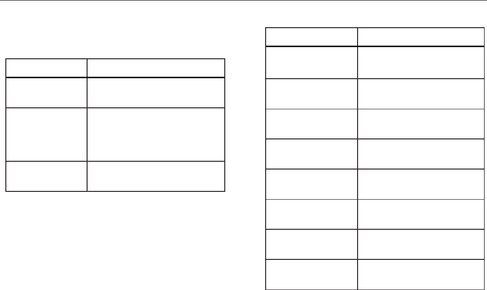
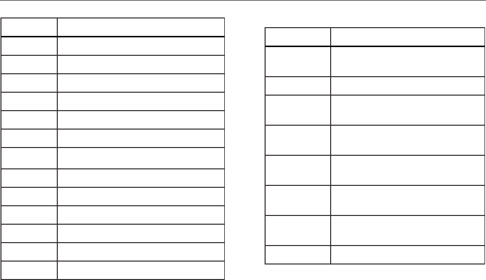
Symbols used on the Product or in this manual are shown in Table 1.
Table 1. Symbols
Symbol Description Symbol Description
Risk of Danger. Important information. See
Manual. Conforms to relevant North American Safety
Standards.
Hazardous voltage. Risk of electric shock. Double Insulated
Conforms to European Union directives. Conforms to relevant Australian EMC standards.
Inspected and licensed by TÜV Product
Services. Battery
This product complies with the WEEE
Directive (2002/96/EC) marking requirements.
The affixed label indicates that you must not
discard this electrical/electronic product in
domestic household waste. Product Category:
With reference to the equipment types in the
WEEE Directive Annex I, this product is
classed as category 9 "Monitoring and Control
Instrumentation" product. Do not dispose of
this product as unsorted municipal waste. Go
to Fluke’s website for recycling information.
Conforms to relevant South Korean EMC
Standards.

Pressure Calibrator
Standard Equipment
5
Standard Equipment
Make sure that the Product shipment is complete. It must
include:
• The Product
• Product Manuals CD
• Getting Started Manual
• Quick Reference Guide
• Test leads
• Calibration Hose kit with fittings
• Carry case
• Calibration certificate
Product Features
Figure 1 and Table 2 shows the location of the buttons,
pressure controls, connection ports, and electrical inputs.
719PRO
Users Manual
6
10
7
11
1
6
2
3
4
5
12
13
14
15
89
16
hix001.eps
Figure 1. Product Interface

Pressure Calibrator
Product Features
7
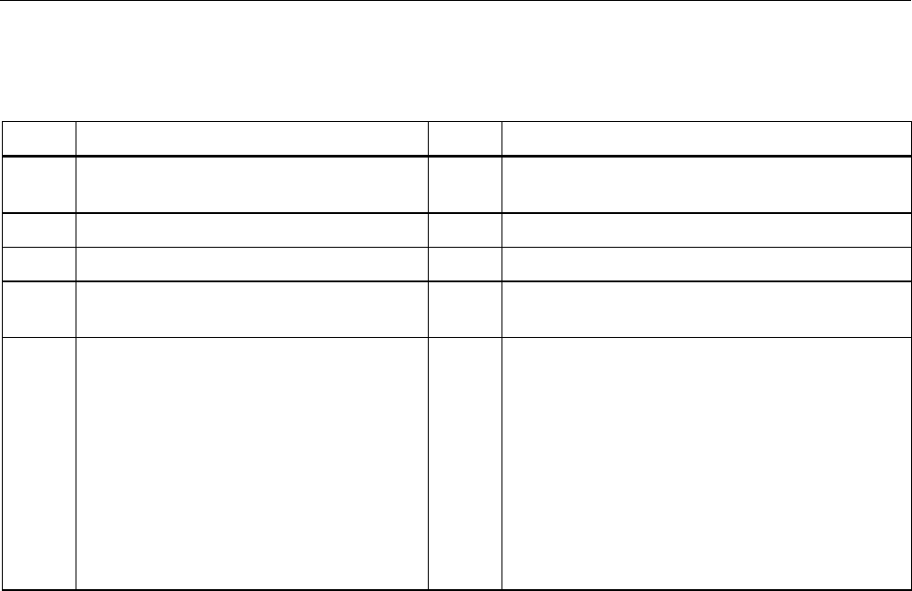
Table 2. Product Features
Item Description
Power button. Turns on and off the Product.
Three function buttons. Used to configure the Product. These buttons correspond to messages on the display.
Zero button. Zeros pressure measurements.
Arrow buttons. Controls mA source/sim. and sets pump and % error limits
Pump button. Runs the electric pump.
Home button. Returns to the main menu screen.
Pressure vernier adjust knob
Pressure source or measurement connector
Input terminals to measure current, volts and contact closure for switch test.
External pressure module connector
RTD probe connector
Pressure/Vacuum Selector
Vent
Firmware programming connector (for factory use only)
Pump clean-out valve
Battery door
719PRO
Users Manual
8
Notes
When is pushed to turn on the Product, a
short startup self-check routine is run. During
that routine, the display shows the current
firmware revision level, auto-shutdown status,
and the range of the internal pressure sensor.
A maximum of 5 minutes warm-up is necessary
for the product to reach rated accuracy. A longer
warm-up period can be necessary for large
changes in ambient temperature. See the “Zero
Function Use” section for more about zeroing
the pressure sensor displays. It is recommended
that pressure ranges be zeroed each time the
Product is started.
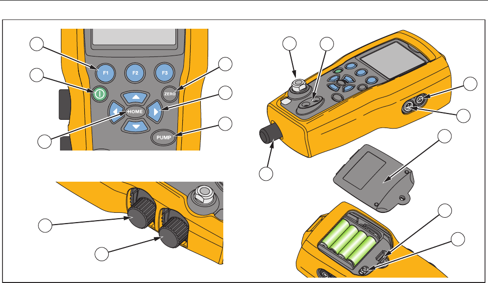
Display
The display has two main regions:
• The menu bar (located at the bottom of the screen) is
used to access the Product menu.
• The main display has a maximum of three process
measurement sub-regions.
These sub-regions will be referred to as the UPPER,
MIDDLE and LOWER displays. Figure 2 shows the
location of the different display fields while Table 3
describes them.
1
3
4
2
hix007.eps
Figure 2. Display

Pressure Calibrator
Product Features
9
Table 3. Display Functions
Item
Number Name Description
Primary
Parameters
Shows what is being
measured.
Span
Indicator
Shows the percent of the
4 mA to 20 mA span. (For
mA and mA loop functions
only.)
Pressure
Units
Shows one of 15 pressure
units available for display.
Units Shows the unit of measure
for the display.
Language Selection
The Product user interface is available in three
languages:
• English
• Norwegian
• German
To select a user interface language:
1. Turn the Product off.
2. Hold down , , and simultaneously.
3. As the Product powers up, the display shows the
language in the top left corner of the display. Repeat
the procedure to show each subsequent language.
Once the necessary language is shown, the Product
user interface stays in that language until another
language is chosen.

719PRO
Users Manual
10
Home Menu Functionality
There are three options for the Home Menu:
• MENU
• Active Display (LOWER, MIDDLE, or UPPER)
• LIGHT
These options are shown across the bottom of the
display.
From anywhere within the menu structure, push to
get back to the Home Menu.
Backlight Use
From the Home Menu, push to toggle on and off the
backlight. This is one of the few functions that cannot be
controlled by the serial interface. There are no user-
configuration settings for the backlight.
The MENU Option
Push to access the Product Main Menus that start with
CONFIG. Then push and to go to subsequent
menus.

Pressure Calibrator
Product Features
11
Main Menu Functionality
There are three options on the Main Menu, shown below:
hix021.eps
Set the Active Display
The active display is indicated by the center option on the
Main Menu. Push from this menu to toggle the active
display (UPPER, MIDDLE, or LOWER).
Set Active Display Parameters
To set the parameters of the active display, push from
the Main Menu to go to the Active Display Configuration
menu, shown below:
hix022.eps
Push to toggle through the selections for each
parameter of the active display. The first parameter is
Mode. Since voltage, current, and switch test modes all
use the same jacks, two of these functions cannot be
used at the same time. The ability to select some
functions is limited based on what is already selected on
a different display.
Push to change to the NEXT active display parameter.
Only RTD and Pressure modes have a second
parameter. RTDs can be read in Celsius or Fahrenheit.
Pressures can be read in 15 engineering units.
With a single display, the modes below are available.
Push to access each mode:
• [P1] = Pressure internal sensor
• [EXT] = Pressure with external pressure module
• [P1] ST = Switch Test with left side sensor
• [EXT] ST = Switch Test with external pressure
module
719PRO
Users Manual
12
Note
mA functions are only available on the lower
display.
• mA measure = Milliamps measure without loop
power
• mA w/24V = Milliamps measure with loop power
• mA source = Milliamps source
• mA sim = Milliamps simulate an external supply from
the UUT
• VOLTS = Voltage Measure
• RTD = RTD Temperature Measurement (if a probe is
connected)
Table 4 shows functions available at the same time. An X
in a column shows that the mode in the active display is
not available if the mode in that row is in operation on a
different display.
Table 4. Mode Concurrency
OTHER DISPLAYS
Current Display
[P1] [EXT] [P1] ST [EXT] ST mA mA
Loop VOLTS RTD
[P1]
[EXT]
[P1] ST X X X X X
[EXT] ST X X X X X
mA X X X X
mA Loop X X X X
Volts X X X X
RTD
X = Not a valid mode

Pressure Calibrator
Product Features
13
Zero Function Use
If a pressure mode is selected and pressure is within the
zero limit, the Product zeros the active display when Z is
pushed. The zero limits are within 10 % of the full-scale
range of the selected sensor. If the display shows “OL,”
the zero function will not operate.
Note
Z is only used for pressure.
Internal Sensor and Pressure Module (non-
absolute)
When a sensor or module is selected on the active
display, and Z is pushed, the Product subtracts the
current reading from the output. The zero limits are within
10 % of the full-scale range of the selected sensor. If the
display shows “OL,” the zero function will not operate.
Absolute Pressure
When an absolute pressure range is selected on the
active display, and Z is pushed, the Product prompts for
the barometric reference pressure as in the screen below.
hix023.eps
Push and to use the on-screen arrows to record the
correct barometric reference pressure. The sensor port
should be open (vented) to atmosphere while this
procedure is done.

719PRO
Users Manual
14
Other Menu Controlled Functions
There are 12 “sub-main” menus that can be accessed
with from the Main Menu. A “sub-main” menu contains
three options. The first option is unique to the function.
The second and third options of a “sub-main” menu are
always the same. goes to the next “sub-main” menu.
For the last “sub-main” menu, goes back to home.
Note
If a “sub-main” menu has subordinate menus, it
will be referred to as {function} Main Menu. For
example, the display contrast sub-main menu
will be called the Contrast Main Menu. If not, it
will be called the {function} menu.
The 12 sub-main menus are:
• CONFIG (Main Menu start point)
• %ERROR
• MINMAX
• CONTRAST
• LOCK CFG
• SETUPS
• AUTO OFF
• DISPLAY
• PROBE TYPE
• DAMP
• HART
• PUMP
Set the Contrast
From the Contrast main menu, push to access the
Contrast Adjustment Menu. See the Contrast Main Menu
below.
hix024.eps
Push and to adjust the display contrast to the
necessary level. Push to finish the adjustment and go
home as shown below.
hix025.eps
Pressure Calibrator
Product Features
15
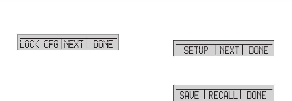
Lock and Unlock Configurations
Use the LOCK CFG or UNLOCK CFG options of the
Configuration Lock Menu (CONFIG), shown below, to
lock or unlock the display configuration.
hix026.eps
When the LOCK CFG option is pushed, the menu display
goes home and the menu configuration option on the
Main Menu is locked. All menus are locked with the
exception of:
• Min Max menu
• Contrast Adjustment menu
• Configuration Lock menu
When the UNLOCK CFG option is selected, the
configuration is unlocked and the menu display goes to
the subsequent sub-main menu.
Save and Recall Setups
The Product automatically saves the current setup for
recall at power up. Five setups can be accessed through
the SETUPS menu. Select the SETUPS option from the
Setups Main Menu shown below.
hix027.eps
Push to store a setup, to show the setup, or to
do nothing and go to the Main Menu.
hix028.eps
719PRO
Users Manual
16
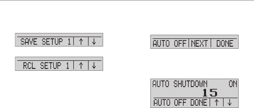
If or is pushed, use the on-screen arrows, as shown
below, to select the setup location. Then use to save
the current setup into the selected location or to recall
the setup stored in the selected location. The display
menu automatically goes to the Main Menu.
hix029.eps
hix030.eps
Set Auto Off Parameters
The Product can be set to automatically power off after a
chosen number of minutes. This function can also be
disabled. To set the auto off parameters, push on the
Auto Off Main Menu shown below.
hix031.eps
Push or to select the number of minutes before the
Product turns off or scroll down to 0 to disable Auto Off as
shown below.
hix032.eps
Push to set the parameters and go to the main menu.
The auto off time is reset when a key is pushed.
Pressure Calibrator
Product Features
17
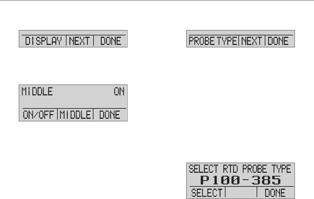
Activate and Deactivate a Display
From the Display Main Menu, push to access the
Display Activation Menu.
hix033.eps
The {display} option can be used to select which display
is active. The selected display and current on/off state are
shown in the lower display as seen below.
hix034.eps
Push to save the changes and go back to the Main
Menu. When a display is deactivated, its configuration is
saved. When the display is activated, its configuration is
compared against the configurations of the other
currently-active displays. If the configurations are in
conflict, the recalled display configuration is changed to
prevent conflict. If all three displays are deactivated, the
LOWER display comes on automatically.
Set the RTD Probe Type
Push from the Probe Type Main Menu to access the
RTD Probe selections.
hix035.eps
There are four probe types to select from:
• P100-385 (select this type for use with Fluke-
720RTD probe accessory)
• P100-392
• P100-JIS
• CUSTOM
Push to select the necessary probe type (see the
figure below). Push to store the change and go to the
Main Menu.
Note
The default probe type is PT100-385.
hix036.eps

719PRO
Users Manual
18
Damping
Turn Damping on or off with the Damping menu selection.
When damping is on, the Product shows a running
average from ten measurements. The Product makes
approximately three indications per second.
HARTTM Resistor
An internal 250 Ω HART resistor can be enabled when
the Product operates in the mA Measure-24 V mode. This
lets a HART Communicator be connected across the mA
terminals. It is not necessary to add an external resistor.
Note
When the HART resistor is on, the maximum
load-driving capacity is 750
Ω
.
Pump Limits
To prevent overpressure of sensitive devices, the
maximum pressure (pump limit) can be set. When in this
mode, use the arrow softkeys to set the maximum
pressure.
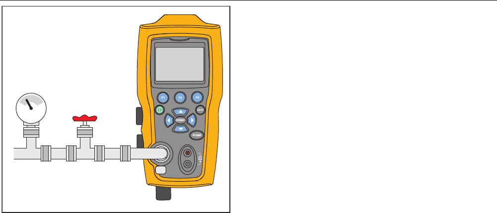
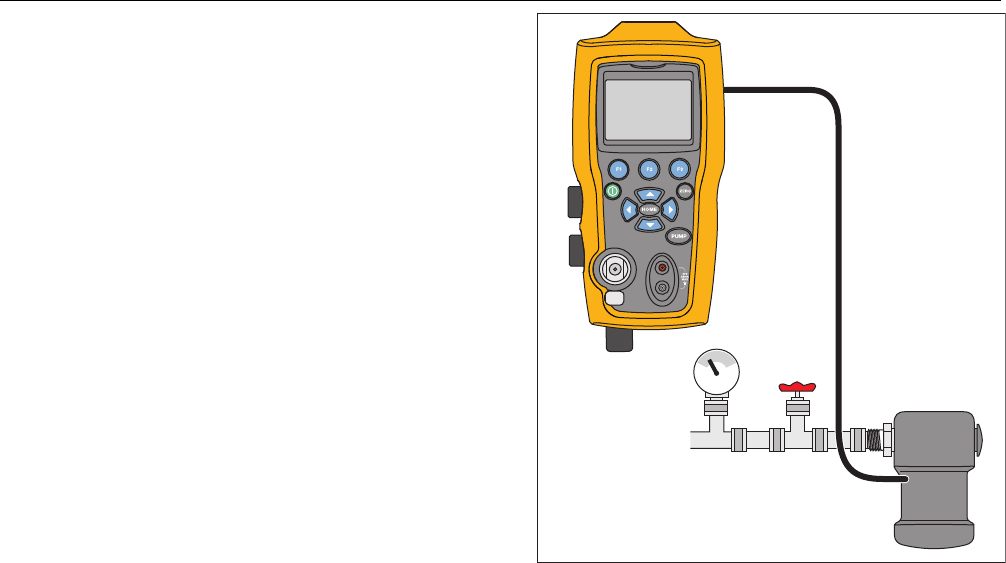
Initial Setup and Basic Pressure
Generation
The Product is supplied with a special low-volume
calibration hose kit for faster pumping to pressure and
quick pressure stabilization. The necessary “quick-fit”
hose connectors and BSP adapter for non-NPT
applications are also included. Fluke recommends that
this type of hose be used to get the best performance
from the Product. When the fittings are installed and the
Product is connected to the unit under test (UUT), the
Product is ready. Figure 3 shows a typical setup.
1. Before pressure is generated, make sure the Product
is configured for the application. If necessary, review
the “Calibrator Interface” section to select the correct
configuration.
2. Make sure that the pressure vacuum knob is set for
the correct function (+ for pressure and – for
vacuum).
Pressure Calibrator
Initial Setup and Basic Pressure Generation
19
Valve
hix009.eps
Figure 3. Pump Connection
3. Close the vent knob.
4. Push the pump key and see the pressure (or
vacuum) increase until the necessary pressure is
reached.
Note
The pump motor speed will start slowly when
pressure is low (<15 psi) for better control at low
pressures.
5. Use the fine adjustment vernier to fine tune the
pressure/vacuum indication as necessary.
6. To fully decrease or bleed off the pressure, slowly
turn the vent knob to the open position. When this is
done carefully, the pressure-bleed rate can be
carefully controlled and this helps when taking down-
scale pressure readings.

719PRO
Users Manual
20
Electric Pump Considerations
The Product uses a small, battery-powered pneumatic
pump that can quickly build rated high pressure. Because
the pump has an upper pressure generation limit, there
may be atmospheric conditions where it cannot go to full-
scale pressure. High-altitude use (about 3000 ft or
1000 meters), or use at cold temperatures, can limit the
pump to about 90 % of its rated pressure. In these cases,
the vernier adjustment can be used to supply additional
pressure necessary if full-scale pressure must be
supplied.
In these situations, start the calibration with the vernier in
the full counter-clockwise position and then, when the
electric pump reaches its limit, turn the vernier clockwise.
This will raise the pressure to set the necessary reading.
See Figure 3.
Measure Pressure
To measure pressure, connect the Product with the
correct fitting. Select a pressure setting for the display
that is used. The Product has one internal sensor and
many optional external sensors (EPMs) are available.
Make sure to choose the sensor based on working
pressures and accuracy.
Warning
To prevent personal injury:
• Pressure sensors can be damaged
and/or personnel injury can occur due to
improper application of pressure. Refer
to Table 9 for information on
overpressure and burst pressure ratings.
Vacuum should not be applied to any
gauge pressure sensor. The Product
display shows “OL” when an
inappropriate pressure is applied. If “OL”
is shown on any pressure display, the
pressure should be reduced or vented
immediately to prevent Product damage
or possible personnel injury. “OL” is
shown when the pressure exceeds 110 %
of the nominal range of the sensor or
when a vacuum in excess of 2 PSI is
applied on gauge range sensors.
• Push Z to zero the pressure sensor
when vented to atmospheric pressure.
Pressure Calibrator
Measure Pressure
21
Note
To ensure accuracy of the Product, the Product
must be zeroed before a device is calibrated.
See the “Zero Function Use” section.
Media Compatibility
The Product has a unique user-accessible valve cleaning
port for easy pump service. See the “Clean the Valve
Assembly” section for how to clean these valves. Make
sure to only expose the Product to clean, dry gases.
Measure Pressure with External Modules
The Product has a digital interface to be used with
external pressure modules. These modules are available
in different ranges and types that include gauge, vacuum,
differential, and absolute. Connect the modules to the
interface and select [EXT] (external sensor). Since the
interface between the Product and the module is digital,
all accuracy and display resolution is derived from the
module. See Figure 4.
Pressure
Module
Valve
hix010.eps
Figure 4. Pressure with External Modules

719PRO
Users Manual
22
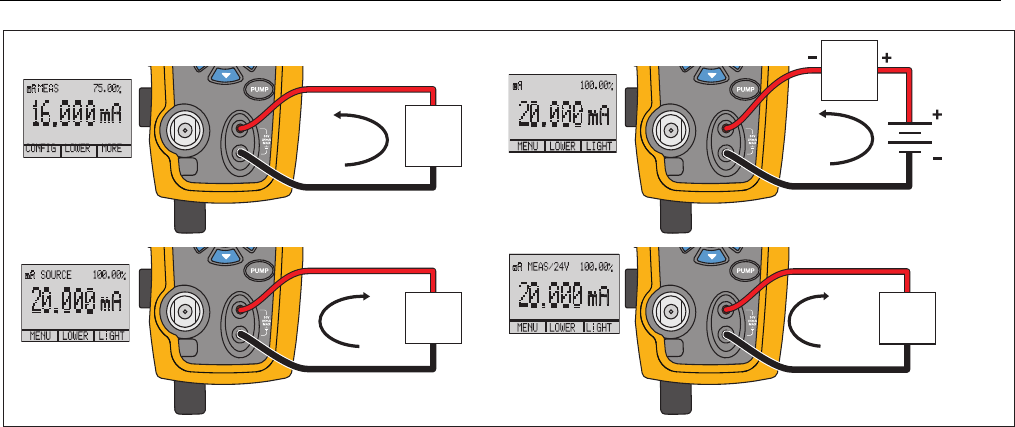
Measure and Generate Current (4 mA to
20 mA)
Use the input terminals on the front of the Product to
measure current, see Figure 5:
1. Select the mA function on the lower display and
select MEASURE. Current is measured in mA and
percentage of range. The range on the Product is set
to 0 % at 4 mA and 100 % at 20 mA.
For example:
If the current measured is shown as 75 % then the
mA value is 16 mA.
Note
The display shows “OL” when the measured
current is more than the nominal range of
current measurement (24 mA).
2. To source current, the same connections are used.
From the configuration screen, select mA source or
mA Sim-2W.
3. This function will only work on the LOWER screen. In
the source mode, the Product supplies 0 mA to
24 mA with its own internal 24-volt supply, whereas
in the simulate mode the Product acts as a two-wire
transmitter and an external 24-volt supply is
necessary.
4. Push any of the arrow softkeys to start the output
mode and use the arrow softkeys to adjust the mA
output. The function keys can also be used to step
the output in either 25 % steps (4, 8, 12, 16, 20 mA)
or 0 % (4 mA) and 100 % (20 mA). While in the mA
output mode, if the loop is opened or the compliance
is exceeded the display flashes “OL”.
Pressure Calibrator
Measure and Generate Current (4 mA to 20 mA)
23
4 to 20mA
4 to 20mA
4 to 20mA
4 to 20mA
Device
Under
Test
Device
Under
Test
UUT UUT
24 V Loop Power
Loop
Power
Supply
SIM-2W
hix011.eps
Figure 5. Measure and Generate Current
719PRO
Users Manual
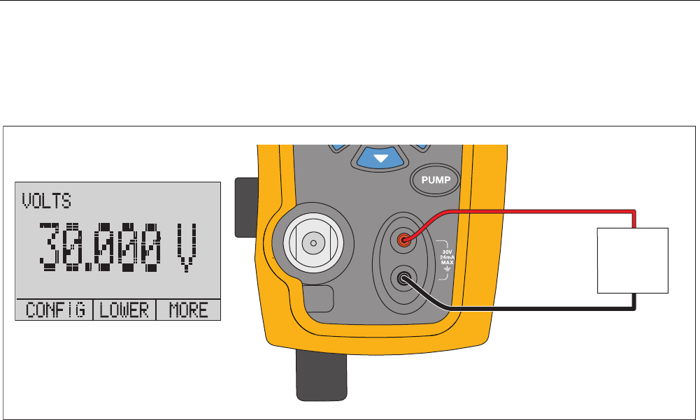
24
Measure Voltage
To measure voltage, use the input terminals on the front of the Product. Select the volts function on one of the displays. The
Product can measure a maximum of 30 V dc. See Figure 6.
Note
The display shows “OL” when the measured voltage is more than the nominal range of the voltage measurement
(30 V).
Device
Under
Tes t
Up to 30V dc
hix015.eps
Figure 6. Voltage Measurement
Pressure Calibrator
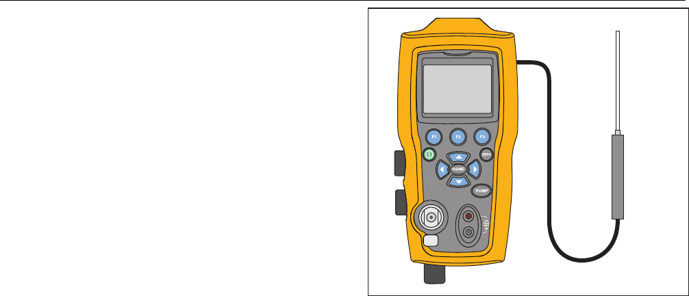
Measure Temperature with an RTD
25
Measure Temperature with an RTD
To measure temperature with an RTD probe, select the
RTD function on one of the displays. Make sure the
correct probe type is selected. See the “Set the RTD
Probe Type” section.
The standard probe has a 10-inch insertion depth with a
¼-inch diameter stainless steel sheath. See Figure 7.
Note
The factory default type is PT100-385 so if the
Product is used with the Fluke 720 RTD Probe
(pn 4366669), it is not necessary to set the
probe type. Connect the probe to the Product
and configure the display to read temperature.
The display shows “OL” when the measured
temperature is outside the nominal
measurement range of the RTD function (below
-40
°
C or above 150
°
C). If a custom probe is
used, enter the R0 and coefficients with the
serial interface (see the “Remote Operation”
section).
RTD Probe
hix016.eps
Figure 7. Temperature Measurement with RTD Probe
719PRO
Users Manual
26
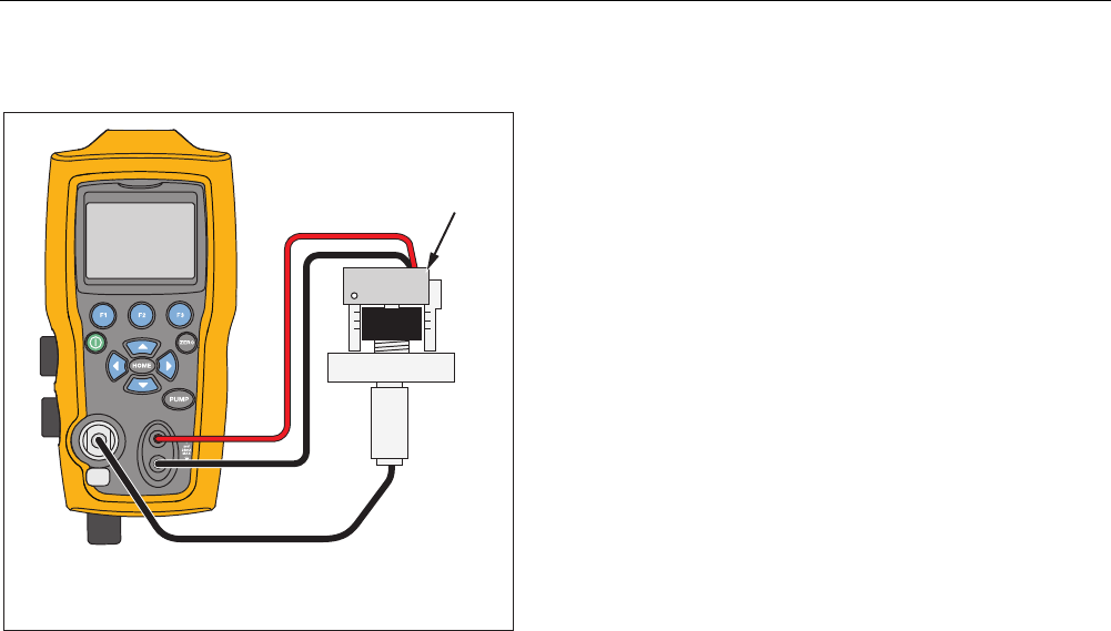
Pressure Switch Test
Connect a pressure switch to the Product as shown in
Figure 8.
Pressure
Switch
Use low volume tubing when possible
hix017.eps
Figure 8. Pressure Switch Connection
To do a pressure switch test:
1. Change the setup to Setup 4 (default switch test)
listed under “Setups” in the MORE configuration
menu choices. The upper display is set to [P1] ST, all
other displays are off.
Note
The pressure switch test can be done with these
functions: [P1] ST, or EXT ST.
Use low-volume tubing when possible.
2. Connect the Product to the switch with the pressure
switch terminals to the pressure switch contacts (de-
energized dry contacts). The polarity of the terminals
does not matter. Connect the pump from the Product
to the input of the pressure switch.
3. Make sure the vent on the pump is open.
4. Zero the Product if necessary.
5. Close the vent after the Product is zeroed. If a
normally closed switch, the top of the display shows
“CLOSE”.
6. Apply pressure with the pump slowly until the switch
opens.
Pressure Calibrator
Pressure Switch Test
27
Note
In switch-test mode the display update rate is
increased to help capture pressure input
changes. Even with this enhanced sample rate,
pressurization of the device under test should be
done slowly to ensure accurate readings.
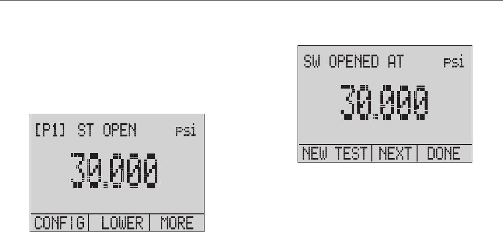
7. When the switch is open, “OPEN” is shown on the
display. Bleed the pump slowly until the pressure
switch closes.
hix043.eps
At the top of the display “SW OPENED AT” and the
pressure that the switch was opened at is shown as in the
figure below.
hix044.eps

719PRO
Users Manual
28
8. Push the “NEXT” option to view when the switch
closed, and the deadband as seen below.
hix045.eps
hix046.eps
9. Push to clear the data and do another test.
10. Push to end the test and return to the standard
pressure setting.
Example:
[P1] ST will return to [P1].
Note
The previous example uses a normally-closed
switch. The basic procedure is the same for a
normally-open switch. The display reads “OPEN”
instead of “CLOSE”.
Pressure Calibrator
Transmitter Calibration
29
Transmitter Calibration
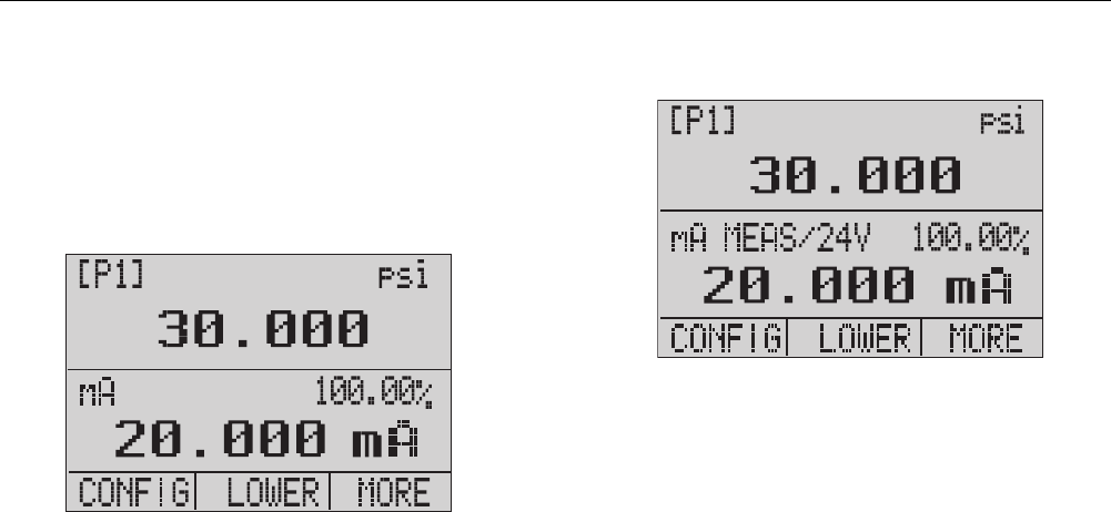
mA Input Function
The mA input function reads back the 4 mA to 20 mA
output from the device being calibrated. This can be done
in one of two ways:
1. Passively – Where the device under test directly
regulates or generates 4 mA to 20 mA and can be
read by the Product.
hix047.eps
2. Actively – Where the Product supplies 24 V dc loop
power to the device under test to power the device
while reading the resulting 4 mA to 20 mA signal.
hix048.eps

719PRO
Users Manual
30
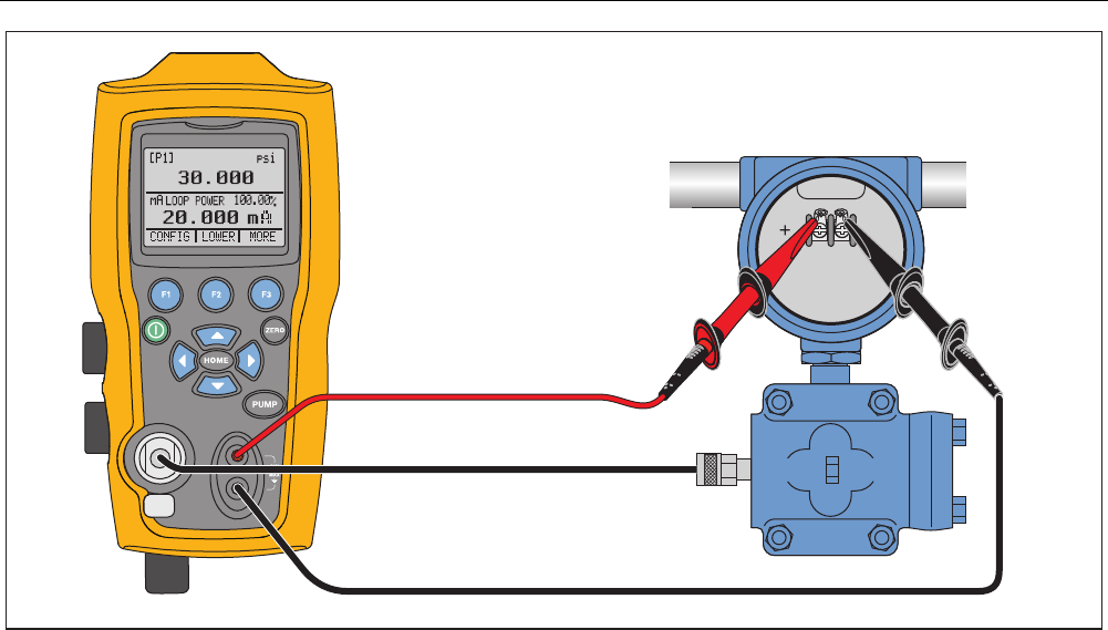
Pressure-to-Current Transmitter Calibration
To calibrate a pressure-to-current transmitter (P/I):
1. Connect the Product and the pump to the transmitter.
See Figure 9.
2. Apply pressure with the pump.
3. Measure the current output of the transmitter.
4. Ensure the reading is correct. If not, adjust the
transmitter as necessary.
Note
Use low-volume tubing when possible.
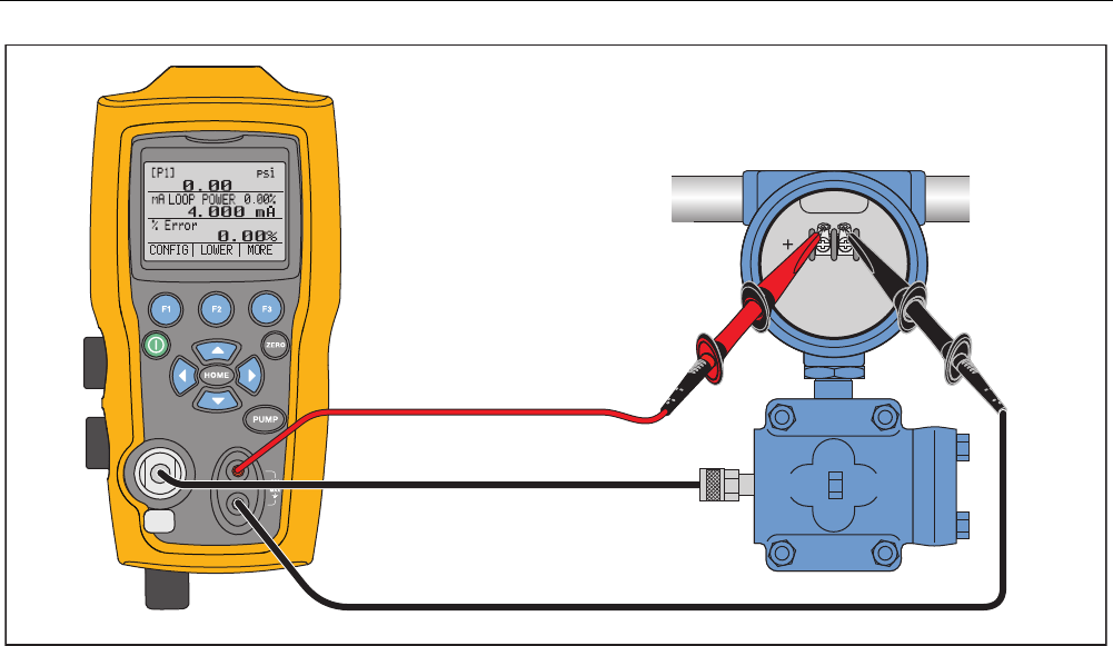
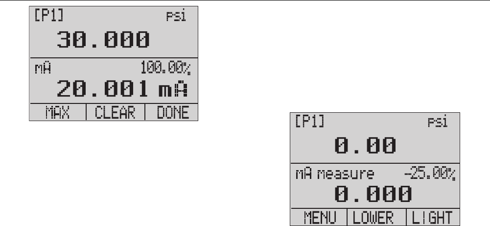
Percent Error Function
The Product features a unique function which can
calculate pressure vs. milliamp error as a percentage of
the 4 mA to 20 mA loop span. The percent error mode
uses all three screens and has a unique menu structure.
It simultaneously shows pressure, mA, and percent error.
See Figure 10.
Pressure Calibrator
Transmitter Calibration
31
hix018.eps
Figure 9. Pressure-to-Current Transmitter Connections
719PRO
Users Manual
32
hix019.eps
Figure 10. Percent Error Function Connection
Pressure Calibrator
Transmitter Calibration
33
Example:
A pressure transmitter under test is 30 psi (2 Bar) Full-
Scale and regulates a corresponding 4 mA to 20 mA
signal. Program a 0 psi to 30 psi pressure span into the
Product and the Product calculates and shows the
deviation or %Error from the expected 4 mA to 20 mA
output. This eliminates the need for manual calculations
and helps when it is difficult to set an exact pressure with
an external pump.
To use the %ERROR function:
1. From the Main Menu, push .
2. Push .
3. Push to start the %ERROR option.
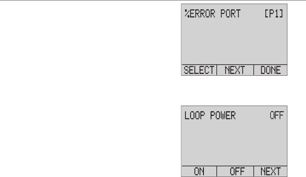
4. Push to configure the option. The first option sets
the Port.
5. Push to scroll through the port choices.
6. When finished, push .
hix049.eps
7. Loop Power can be toggled on/off as seen below.
Push when done.
hix050.eps
719PRO
Users Manual
34
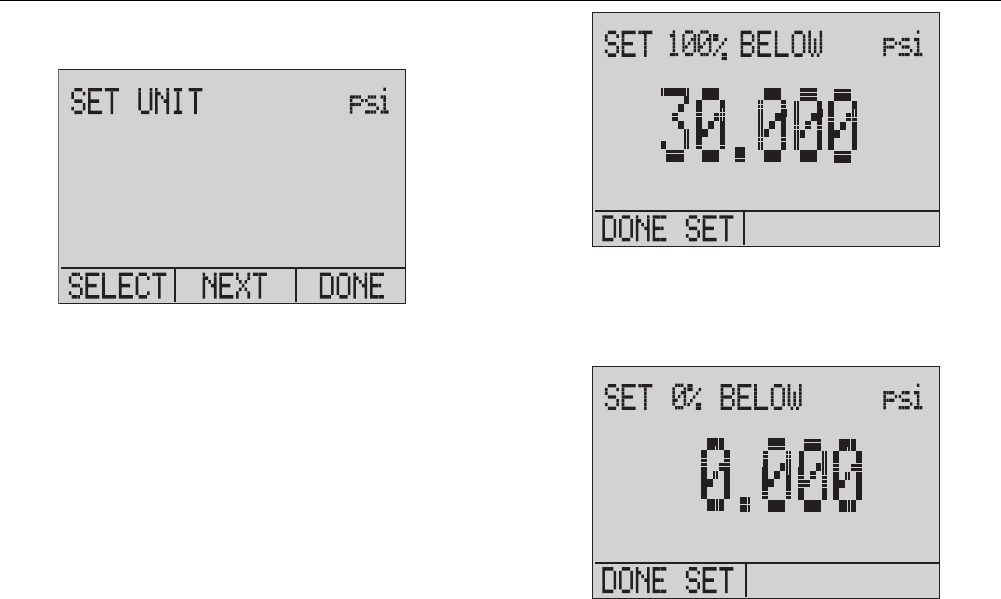
8. Push to toggle through the unit options, and push
to move on.
hix051.eps
9. Use the arrow keys to set the 100 % point of the
desired pressure range, select DONE SET when
finished.
hix052.eps
10. Use the arrow keys to set 0 % point and select
DONE SET when finished and the % ERROR mode
will be ready to use.
hix053.eps
Pressure Calibrator
Minimum and Maximum Storage Capability
35
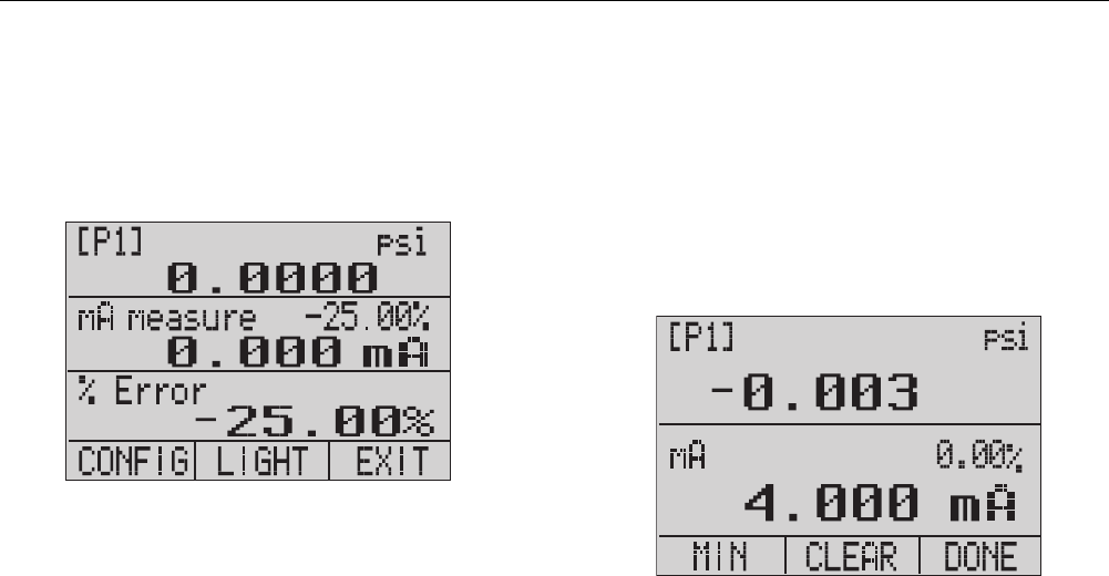
Note
The 0 % and 100 % point will be saved in non-
volatile memory until they are changed again by
the user for the internal sensors, and external
pressure modules. When an external module is
used, the 0 % and 100 % are set to low and full
scale of the module until the user changes it, or
if it was previously saved.
hix054.eps
Minimum and Maximum Storage
Capability
The Product has a min/max feature to capture the
minimum and maximum values of any displayed
parameter.
Step through the menu options to access the min/max
function. “MIN/MAX” is shown on the display above .
Push to toggle the display through the min/max values
that are stored in the min/max registers. These readings
are live so that the new min/max values will be recorded
while in this mode.
hix055.eps
719PRO
Users Manual
36
hix056.eps
To reset the min/max registers, push for “CLEAR”.
These registers are also cleared at power-up or when the
configuration is changed.
Factory Setups
The Product is loaded with five commonly used factory
setups. To access these SETUPS, select from the MORE
configurations options. These setups are shown below.
Note
Any of these setups can be changed and saved.
Setup 1: The upper display is set to [P1] mode and the
lower is set to mA, middle is off.
hix057.eps
Pressure Calibrator
Factory Setups
37
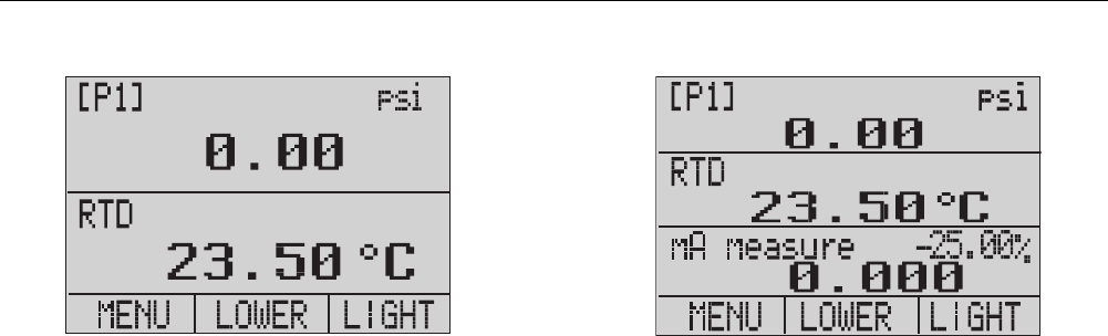
Setup 2: The upper display is set to [P1] mode and the
lower is set to RTD, middle is off.
hix058.eps
Setup 3: The upper display is set to [P1] mode and the
middle is set to RTD, lower is mA.
hix059.eps
719PRO
Users Manual
38
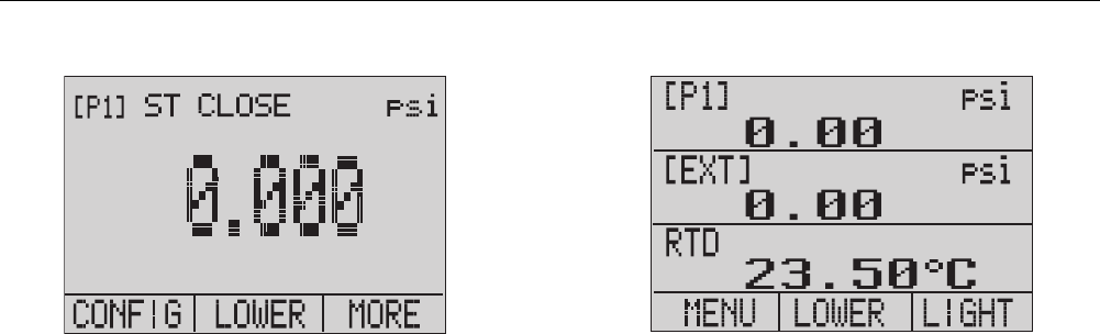
Setup 4: The lower display is set to [P1] switch test, the
other displays are off.
hix062.eps
Setup 5: The upper display is set to [P1], the middle
display is set to [EXT] and the lower display is set to RTD.
hix060.eps

Pressure Calibrator
Custody Transfer / Flow Calibration
39
Custody Transfer / Flow Calibration
The Product is ideal for flow computer calibration. Every
manufacturer of flow computers has a different calibration
procedure, but most call for calibration of three
parameters: static pressure, differential pressure and
temperature. To facilitate these measurements, recall
setup #5 on the Product.
1. Connect the Product to the static and differential
pressures. ([P1], EXT) Then connect the RTD sensor
to the Product.
2. With the reading of the RTD, static, and differential
pressures, make sure the flow computer has the
correct reading. If not, adjust the flow computer as
necessary.
Remote Operation
Remote Interface
The Product can be remotely controlled with a PC
terminal or by a computer program that runs the Product
in an automated system. It uses an RS-232 serial port
connection for remote operation.
Note
To use the remote control option, a custom
miniature circular to USB interface cable, PN
4401616 must be purchased separately. To
contact Fluke refer to the “Contact Fluke”
section.
With this connection the user can write programs on the
PC, with Windows languages like Visual Basic to operate
the Product, or use a terminal program similar to Hyper
Terminal, to enter single commands. Typical RS-232
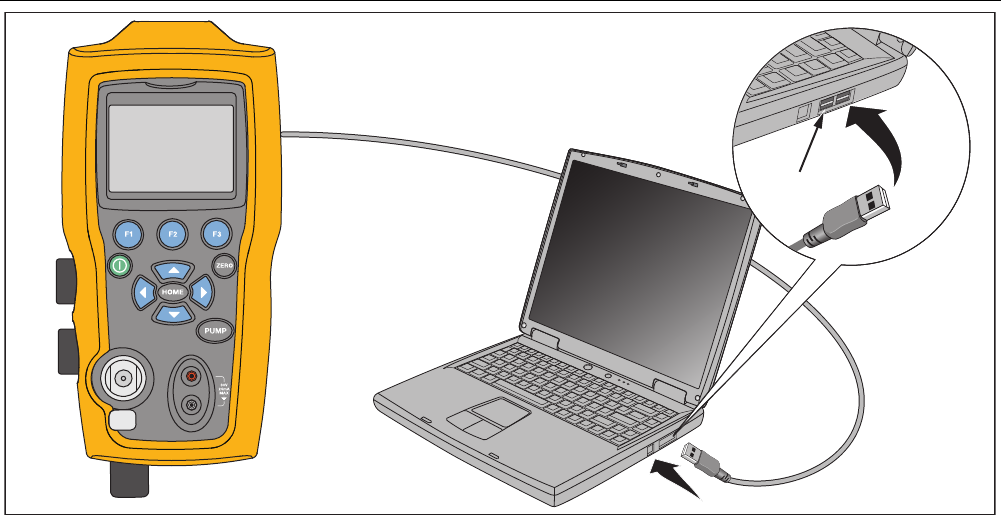
remote configurations are shown in Figure 11.
719PRO
Users Manual
40
USB Port
hix020.eps
Figure 11. Typical Remote Connection

Pressure Calibrator
Remote Operation
41
Set up the RS-232 Port for Remote Control
Note
The RS-232 connection cable should not exceed
15 m unless the load capacitance measured at
connection points is less than 2500 pF.
Serial parameter values:
• 9600 baud
• 8 data bits
• 1 stop bit
• no parity
• Xon/Xoff
• EOL (End of Line) character or CR (Carriage Return)
or both
Note
To use the remote control option, a custom
miniature circular to USB interface cable, PN
4401616, must be purchased separately.
Connect the Product to the computer, attach the
miniature circular connector end of the cable to the
pressure module port on the right side of the Product and
the USB connector to the computer. The Product should
be turned off prior to making the connection and then
turned on.
For remote operation of the Product, connect it to a COM
port on the PC as in Figure 11. Use a terminal emulator
program and follow the subsequent procedure:
1. Start the terminal emulator program.
2. Select New Connection.
3. For Name enter “Fluke 719PRO”. Select the serial
port that the Product is connected to.
4. Enter the above information for port settings.
5. Select ASCII setup from File/Properties/Settings and
mark these choices:
• Echo typed characters locally
• Wrap lines that exceed terminal width
6. Select Ok.
7. To see if the port works enter *IDN?. This command
will return information on the Product.

719PRO
Users Manual
42
Change Between Remote and Local Operation
There are three modes of operation of the Product: Local,
Remote, and Remote with Lockout. Local mode is the
default mode. Commands may be entered with the
keypad on the Product or with a computer. In Remote
mode the keypad is disabled and commands may only be
entered with a computer. If [GO TO LOCAL] is chosen
from the display menu, the Product restores keypad
operation. In Remote with Lockout, the keypad cannot be
used.
To switch modes:
1. To enable Remote mode, enter the serial command
REMOTE at the computer terminal.
2. To enable Remote with Lockout, enter “REMOTE
LOCKOUT” in either order.
3. To switch back to local operation enter LOCAL at the
terminal. This command also turns off LOCKOUT if it
is on. For more information on commands, refer to
the “Remote Commands” section.
Command Use and Types
Refer to the “Remote Commands” section for all available
commands. The Product may be controlled by commands
and queries. All commands may be entered with upper or
lower case. The commands are divided into the
categories listed below:
Calibrator Commands
Only the Product uses these commands. For example:
VAL?
asks for the values displayed on the Product display.
Common Commands
Standard commands used by most devices. These
commands always begin with an “*”.
For example:
*IDN?
tells the Product to return its identification.

Pressure Calibrator
Remote Operation
43
Query Commands
Commands that ask for information, they always end with
a “?”. For example:
FUNC?
returns the current modes of the Product displays.
Compound Commands
Commands that contain more than one command on one
line. For example:
RTD_TYPE PT385_100;RTD_TYPE?
Sets the Product to RTD type PT385_100 and queries it
to verify. It will return:
PT385_100
Character Processing
The data entered into the Product is processed as
follows:
• ASCII characters are discarded if their decimal
equivalent is less than 32 (space), except 10 (LF)
and 13 (CR):
• Data is taken as 7-bit ASCII
• The most significant data bit is ignored.
• Upper or lower case is acceptable.

719PRO
Users Manual
44
Response Data Types
The data returned by the Product can be divided into four
types:
Integer
For most computers and controllers they are decimal
numbers that range from -32768 to 32768. For example:
FAULT? could return 110
Refer to Table 8 for more information on error codes.
Floating
Floating numbers have up to 15 significant figures and
exponents. For example:
CPRT_COEFA? returns 3.908300E-03
Character Response Data (CRD)
Data returned as keywords. For example:
RTD_TYPE? returns PT385_100
Indefinite ASCII (IAD)
Any ASCII characters followed by a terminator. For
example:
*IDN? returns FLUKE,719PRO,1234567,1.00
Calibrator Status
Error Queue
If an error occurs due to invalid input or buffer overflow,
its error code is sent to the error queue. The error code
can be read from the queue with the command FAULT?.
The error queue holds 15 error codes. When it is empty,
FAULT? returns 0. The error queue is cleared when
power is reset or when the clear command *CLS is
entered.
Input Buffer
The Product stores all received data in the input buffer.
The buffer holds 250 characters. The characters are
processed on a first in, first out basis.
Pressure Calibrator
Remote Operation
45
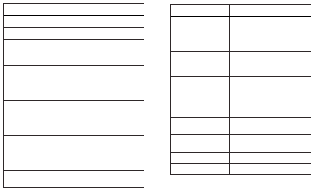
Remote Commands and Error Codes
Tables 5, 6, 7, and 8 list all commands, and their
descriptions, that are accepted by the Product.
Table 5. Common Commands
Command Description
*CLS (Clear status) Clears the error
queue.
*IDN?
Identification query. Returns the
manufacturer, model number,
serial number, and firmware
revision level of the Product.
*RST Resets the Product to the
power up state.
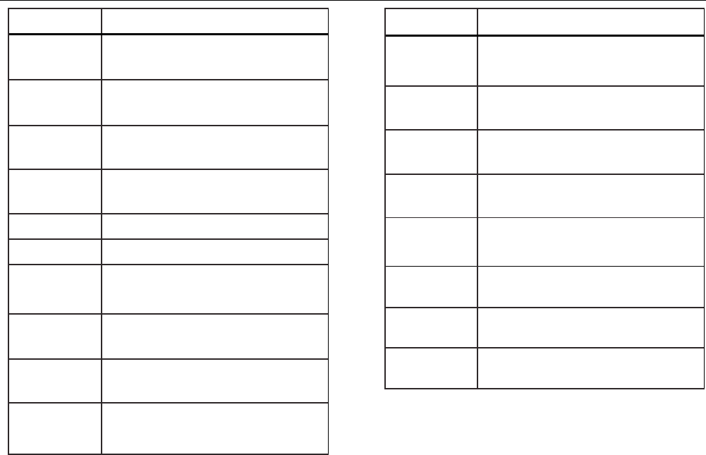
Table 6. Calibrator Commands
Command
Description
CPRT_COEFA Sets the custom RTD
coefficient A
CPRT_COEFA? Returns the custom RTD
coefficient A
CPRT_COEFB Sets the custom RTD
coefficient B
CPRT_COEFB? Returns the custom RTD
coefficient B
CPRT_COEFC Sets the custom RTD
coefficient C
CPRT_COEFC? Returns the custom RTD
coefficient C
CPRT_R0 Sets the custom RTD R0
resistance
CPRT_R0? Returns the custom RTD R0
resistance
719PRO
Users Manual
46
Command
Description
DAMP Turns Damp on or off.
DAMP? Returns if DAMP is on/off
DISPLAY Turns on/off the displays
specified in the command
DISPLAY? Returns which displays are
on/off
ERROR_LOOP Turns loop power on or off in
percent error mode
ERROR_LOOP? Returns the current state of
loop power in error mode
ERROR_MODE Turns percent error mode on
or off
ERROR_MODE? Returns whether percent
error mode is on or off
ERROR_PORT Set the pressure port for
percent error mode
ERROR_PORT? Returns the pressure port for
percent error mode
Command
Description
FAULT? Returns the most recent
error code
FUNC Sets the display mode as
specified in the command
FUNC?
Returns the current mode of
the upper, middle, and lower
display
HART_ON Turns the hart resistor on.
HART_OFF Turns the hart resistor off.
HART? Returns the current state of
the Hart resistor.
HI_ERR Sets the 100 % of span limit
for percent error mode
HI_ERR? Returns the 100 % of span
limit for percent error mode
IO_STATE Set the Product's mA state.
IO_STATE? Return the Product's mA state.
Pressure Calibrator
Remote Operation
47
Command Description
LOCAL Returns user to manual operation of
the Product
LOCKOUT Locks out the keypad of the Product in
remote operation
LO_ERR Sets the 0 % of span limit for percent
error mode
LO_ERR Returns the 0 % of span limit for
percent error mode
MOTOR_ON Turns the motor on.
MOTOR_OFF Turns the motor off.
MOTOR? Returns the current state of the Hart
resistor
OHMS? Returns ohms value measured from
the RTD
OUT Set the Product to output the
requested current.
OUT? Returns the value of the current being
simulated.
Command Description
PRES_UNIT Set the pressure unit for the indicated
display
PRES_UNIT? Returns the pressure from the
indicated display
PUMP_LIMIT Sets the approximate value at which
the pump will turn off.
PUMP_LIMIT? Returns the approximate value at
which the pump will turn off.
REMOTE Puts the Product in remote mode
RTD_TYPE Sets the RTD type
RTD_TYPE? Returns the RTD type
SIM Set the Product to simulate the
requested current.
719PRO
Users Manual
48
Command Description
SIM? Returns the value of the current being
simulated.
ST_CLOSE? Returns pressure value at which the
switch closed
ST_DEAD? Returns pressure value of the
deadband of the switch
ST_OPEN? Returns pressure value at which the
switch opened
ST_START Starts a switch test
TEMP_UNIT Set the RTD to read in °F or °C on the
indicated display
TEMP_UNIT? Returns the unit the RTD is set to
VAL? Returns the measured values
ZERO_MEAS Zeros the pressure module
ZERO_MEAS? Returns the zero offset of the
pressure module
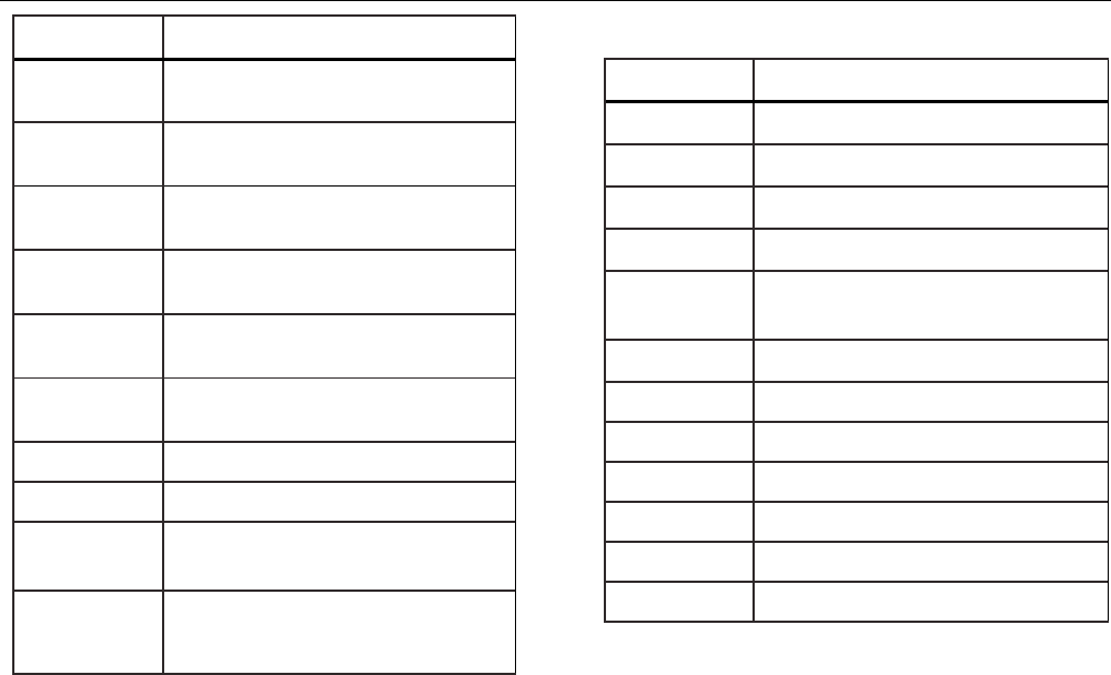
Table 7. Parameter Units
Units Meaning
CEL Temperature in degrees Celsius
CUSTOM Custom RTD type
DCI Current function
DCV Voltage measure function
EXT External pressure measurement
function
FAR Temperature in degrees Fahrenheit
LOWER Designates Lower display
MA Milliamps of current
MEASURE Measure state
MEAS_LOOP Measure with loop power state
MIDDLE Designates Middle display
OHM Resistance in ohms
Pressure Calibrator
Remote Operation
49
Units Meaning
PCT_ERR Percent Error
PERCENT Percent
PT385_100 100 Ohm 385 Platinum RTD type
PT392_100 100 Ohm 392 Platinum RTD type
PTJIS_100 100 Ohm JIS Platinum RTD type
P1 P1 pressure measurement function
RTD Temperature measure function
ST_P1 Switchtest mode with P1
ST_EXT Switchtest mode with external module
SOURCE Source state
SIM Simulate state
UPPER Designates Upper display
V Voltage
Table 8. Error Codes
Error Number Error Description
100 A non-numeric entry was received
where it should be a numeric entry
101 Too many digits entered
102 Invalid units or parameter value
received
103 Entry is above the upper limit of the
allowable range
104 Entry is below the lower limit of the
allowable range
105 A required command parameter was
missing
106 An invalid command parameter was
received
107 Pressure not selected

719PRO
Users Manual
50
Error Number Error Description
108 Invalid sensor type
109 Pressure module not connected
110 An unknown command was received
111 Bad Parameter received
112 The serial input buffer overflowed
113 Too many entries in the command
line
114 The serial output buffer overflowed
Enter Commands
Commands for the Product may be entered in upper or
lower case. There is at least one space required between
the command and parameter, all other spaces are
optional. Almost all commands for the Product are
sequential. Any overlapped commands are indicated as
such. This section briefly explains each of the commands
and describe their general use, which include any
parameters that may be entered with the command as
well as what the output of the command is.
Common Commands
*CLS
Clears the error queue. Also terminates all pending
operations. When programs are written, use before each
procedure to avoid buffer overflow.
*IDN?
Returns the manufacturer, model number, serial number,
and firmware revision of the Product. For example:
*IDN? returns FLUKE,719PRO,1234567,1.00

Pressure Calibrator
Remote Operation
51
Calibrator Commands
CPRT_COEFA
Use this command to entere a custom RTD into the
Product. The numeric value entered after the command is
set as the first coefficient of the polynomial used by the
custom RTD.
For example:
CPRT_COEFA 3.908300E-03 enters 3.908300e-3 as
coefficient A.
CPRT_COEFA?
Returns the number that was entered for the first
coefficient of the polynomial used in the custom RTD.
With the example above, CPRT_COEFA? returns:
3.908300E-03
CPRT_COEFB
This command is used to enter a custom RTD into the
Product. The numeric value entered after the command
will be set as the second coefficient of the polynomial
used by the custom RTD.
For example:
CPRT_COEFB –5.774999E-07 enters –5.774999E-07
as coefficient B.
CPRT_COEFB?
Returns the number which was entered for the second
coefficient of the polynomial used in the custom RTD.
With the example above, CPRT_COEFB? returns:
-5.774999E-07
CPRT_COEFC
This command is used to enter a custom RTD into the
Product. The numeric value entered after the command
will be set as the first coefficient of the polynomial used
by the custom RTD.
For example:
CPRT_COEFC –4.183000E-12 enters –4.183000E-12
as coefficient C.
CPRT_COEFC?
Returns the number that was entered for the third
coefficient of the polynomial used in the custom RTD. The
example above CPRT_COEFC? returns:
–4.183000E-12

719PRO
Users Manual
52
CPRT_R0
Sets the 0 ° resistance, R0, in the custom RTD. The value
must be entered with a unit label. Refer to Table for
assistance.
For example:
CPRT_R0 100 OHM sets R0 to 100 Ω.
CPRT_R0?
Returns the value for the resistance in custom RTD. The
above example returns:
1.000000E+02, OHM
DAMP
Turns on or off the damping function.
For example:
If DAMP ON is sent, this will turn on the damping
function.
DAMP?
Returns the current state of the damping function.
For example:
If DAMP? is sent, it will return ON if the damping function
is on.
DISPLAY
Turns on or off the indicated display.
For example:
If DISPLAY LOWER is sent ON, this will turn on the lower
display.
DISPLAY?
Returns the current state of the each of the displays.
For example:
If DISPLAY? is sent, it will return ON, ON, ON if the all
the displays are on.

Pressure Calibrator
Remote Operation
53
FAULT?
Returns the error code number of an error that has
occurred. The command may be entered when the
previous command did not do what it was meant to do.
For example, if a value for current output is entered that is
bigger than the supported range (0 mA -24 mA) FAULT?
returns:
103 which is the code number for an entry over range.
Refer to Tables 5, 6, 7, and 8 for more information on
error code numbers.
ERROR _LOOP
Turns on or off loop power in percent error mode.
For example:
To set loop power on, send ERROR_LOOP ON.
ERROR _LOOP?
Returns the current state of loop power in percent error
mode.
For example:
If ERROR_LOOP? is sent, it will return ON if loop power is
on in error mode.
ERROR_ MODE
Turns percent error mode on and off.
For example:
To turn on percent error mode, send ERROR_MODE ON.
ERROR _ MODE?
Returns the current state of percent error mode.
For example:
If ERROR_MODE? is sent, it will return ON if the Product is
in percent error mode.

719PRO
Users Manual
54
ERROR_ PORT
Sets the pressure port for percent error.
For example:
To set the pressure port for percent error to [P1], send
ERROR_ PORT P1.
ERROR _ PORT?
Returns the current pressure port for percent error mode.
For example:
If ERROR _PORT? is sent, it will return P1 if the pressure
port in percent error is [P1].
FUNC
Sets the display indicated in argument one to the function
indicated in argument 2.
For example:
To set the lower display to RTD mode send FUNC
LOWER,RTD.
FUNC?
Returns the current mode of all displays. For example, if
the Product is set to [P2] ST on the upper display, [P1] on
the middle, and RTD on the lower, FUNC? returns:
ST_P2,P1,RTD
HART_ON
Turns on the Hart resistor.
HART_OFF
Turns off the Hart resistor.
HART?
Returns the state of the Hart resistor.
For example:
If the Hart resistor was on HART? returns ON.
HI_ERR
Sets the 100 % point for the percent error mode
calculation in the current engineering units.
For example:
To set the 100 % point to 100 psi, send HI_ERR 100.
HI_ERR?
Returns the 100 % point for the percent error mode
calculation.
For example:
If the 100 % point is set to 100 psi, HI_ERR? returns
1.000000E+02, PSI.

Pressure Calibrator
Remote Operation
55
IO_STATE
Sets the input/output/simulate state of the mA function of
the Product. Does not put the Product into mA if it is not
in mA already.
For example:
If the Product is in mA simulate mode, IO_STATE
MEASURE would put it in measure mode.
IO_STATE?
Returns the input/output/simulate state of the mA function
of the Product.
For example:
If the Product was in mA simulate mode IO_STATE?
would return SIM.
LOCAL
Restores the Product to local operation if it was in remote
mode. Also clears LOCKOUT if the Product was in
lockout mode.
LOCKOUT
Send this command to set the lockout state, when the unit
is in REMOTE or if it goes to remote it prohibits use of the
keypad. The lockout state can only be cleared by if the
LOCAL command is sent.
LO_ERR
Sets the 0 % point for the percent error mode calculation
in the current engineering units.
For example:
To set the 0 % point to 20 psi, send LO_ERR 20.
LO_ERR?
Returns the 0 % point for the percent error mode
calculation.
For example:
If the 0 % point is set to 20 psi, LO_ERR? returns
2.000000E+01, PSI.
MOTOR_ON
Turns on the motor.

719PRO
Users Manual
56
MOTOR_OFF
Turns off the motor.
MOTOR?
Returns the state of the motor.
For example:
If the motor was on, MOTOR? returns ON.
OHMS?
Returns the raw ohm value from the RTD.
For example:
If when a P100-385 is measured at 0 °C, OHMS? returns
1.000000E+02, OHM.
OUT
This command also switches the Product into mA output
mode. A number and a unit must be entered after the
command.
For example:
OUT 5 MA sets the current output at 5 mA
OUT?
Returns the output of the Product.
With the above example, OUT? returns 5.000000E-03, A
PRES_UNIT
Used to set the pressure unit for the indicated display.
For example:
To set the pressure unit to psi on the lower display, send
PRES_UNIT LOWER, PSI.
PRES_UNIT?
Returns the pressure unit used when pressure is
measured for each of the 3 displays.
PUMP_LIMIT
Sets the approximate pressure in psi at which the pump
will turn off.
For example:
PUMP_LIMIT 50 sets the approximate value that the
pump will shut off at to 50 psi

Pressure Calibrator
Remote Operation
57
PUMP_LIMIT?
Returns the pump limit. The above example with
PUMP_LIMIT? returns:
50.000
REMOTE
Puts the Product into remote mode. From the remote
mode, the keypad can be used to get back to local mode
unless the command LOCKOUT was entered before
REMOTE. Then the keypad is locked out, and the LOCAL
command must be sent to get back to local operation.
RTD_TYPE
Sets the RTD type. The subsequent list shows RTD types
the way they should be entered after the command:
PT385_100; PT392_100; PTJIS_100; CUSTOM;
For Example:
RTD_TYPE PT385_100 sets RTD type to PT100-385
RTD_TYPE?
Returns the RTD type.
For example:
If the RTD type is PT385_100, RTD_TYPE?, PT100_385
is returned.
SIM
Sets the output for current simulation. This command also
switches the Product into mA simulation mode. A number
and a unit must be entered after the command.
For example:
SIM 5 MA sets the current simulation at 5 mA
SIM?
Returns the output of the current simulation. With the
example above, the output would be: 5.000000E-03, A
ST_START
Starts a switch test.

719PRO
Users Manual
58
ST_CLOSE?
Returns the pressure that the switch closed at in the
current pressure units.
ST_OPEN?
Returns the pressure that the switch opened at in the
current pressure units.
ST_DEAD?
Returns deadband of the switch in the current pressure
units.
TEMP_UNIT
This command is used to set the temperature unit used
when temperature is measured.
The first argument indicates which display to apply the
change to. The second argument is the unit, either CEL
for Celsius or FAR for Fahrenheit.
For example:
To set the temperature unit to Fahrenheit on the lower
display, send TEMP_UNIT LOWER, FAR.
TEMP_UNIT?
Returns the temperature unit, (CEL or FAR) used when
RTDs are measured for each of the 3 displays.
VAL?
Returns the value of any measurement on the upper and
lower display. For example, if the upper display shows
5 mA, and the lower display shows 10 V, then VAL?
returns:
5.000000E-03, A, 1.000000E+01, V
ZERO_MEAS
Zeros the attached pressure module. Enter the value
zeroed in PSI after the command when an absolute
pressure module is zeroed.
ZERO_MEAS?
Returns the zero offset or the reference value for absolute
pressure modules.

Pressure Calibrator
Ranges and Resolution
59
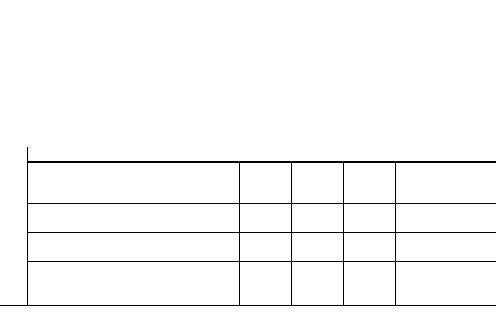
Ranges and Resolution
Ranges and resolutions for the Product are shown in
Table 9.
Table 9. Ranges and Resolutions
Range (PSI) 30 PSI / 2.0 Bar 150 PSI / 10 Bar 300 PSI / 20 Bar
Burst Pressure (PSI) 300 300 600
Proof Pressure (PSI) 60 200 400
Engineering Unit Factor
Psi 1 30.000 150.00 300.00
Bar 0.06894757 2.0684 10.3421 20.684
mbar 68.94757 2068.4 10342.1 20684
kPa 6.894757 206.84 1034.21 2068.4
MPa .00689476 0.2068 1.03421 2.0684
kg/cm2 0.07030697 2.1092 10.5460 21.092
cmH2O @ 4 °C 70.3089 2109.3 10546.3 21093
cmH2O @ 20 °C 70.4336 2113.0 10565.0 21130
mmH2O @ 4 °C 703.089 21093 N/A N/A
mmH2O @ 20 °C 704.336 21130 N/A N/A

719PRO
Users Manual
60
inH2O @ 4 °C 27.68067 830.42 4152.1 8304.2
inH2O @ 20 °C 27.72977 831.89 4159.5 8318.9
inH2O @ 60 °C 27.70759 831.23 4156.1 8312.3
mmHg @ 0 °C 51.71508 1551.5 7757.3 15515
inHg @ 0 °C 2.03602 61.081 305.40 610.81
Proof pressure - maximum allowable pressure without a shift in calibration
Burst pressure - sensor damaged or destroyed; some risk of personnel injury

Pressure Calibrator
Maintenance
61
Maintenance
Replace the Batteries
If the batteries discharge too far, the Product
automatically shuts down to prevent battery leakage.
Note
Use only AA size alkaline, Lithium batteries ,or
rechargeable NiMh cells.
Warning
To prevent possible electrical shock, fire, or
personal injury:
• Remove the batteries if the Product is
not used for an extended period of time,
or if stored in temperatures that exceed
the battery manufacturer’s specification.
If the batteries are not removed, battery
leakage can damage the Product.
• Replace the batteries when the low
battery indicator shows to prevent
incorrect measurements.
• Be sure that the battery polarity is
correct to prevent battery leakage.
• Repair the Product before use if the
battery leaks.
• The battery door must be closed and
locked before you operate the Product.
719PRO
Users Manual
62
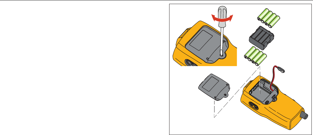
To change the batteries, see Figure 12:
1. Turn off the Product.
2. Turn the Product so that the display is down.
3. With a flat-head screwdriver, remove the battery door
screw.
4. Lift out and disconnect the battery holder.
5. Replace the eight AA batteries with new batteries.
Make sure that the polarity on the batteries is correct.
6. Reconnect the battery holder.
7. Reinsert the battery holder into the battery
compartment.
8. Replace the battery door.
9. Tighten the battery door screw.
hix061.eps
Figure 12. Battery Replacement

Pressure Calibrator
Maintenance
63
Clean the Product
Caution
To avoid damaging the plastic lens and case,
do not use solvents or abrasive cleansers.
Clean the Product with a soft cloth dampened with water
or water and mild soap.
Clean the Valve Assembly
Occasionally, the Product may not work properly due to
dirt or other contamination of the internal valve assembly.
Use the subsequent procedure to clean the valve
assembly. If this procedure does not correct the problem,
a repair kit can be ordered. See the “User-Replaceable
Parts” section.
1. With a small screwdriver, remove the two valve
retention caps located in the battery compartment
area (see Figure 12).
2. After the caps have been removed, gently remove
the spring and ring assembly.
3. Set aside the valve assemblies in a safe area and
clean out the valve body with a cotton swab soaked
in IPA (isopropyl alcohol).
4. Repeat the process several times with a new cotton
swab each time until there is no evidence of
contamination or dirt.
5. Operate the pump handles several times and
recheck for contamination.
6. Clean the O-ring assembly and the O-ring on the
retention caps with IPA and inspect the O-rings
closely for any damage or excessive wear.
Replacements are included in the repair kit, if
necessary.
7. Inspect the springs for wear or loss of tension. They
should be approximately 8.6 mm long in the relaxed
state. If shorter, they may not provide sufficient seal
tension. Replace if necessary.
8. Once all parts have been cleaned and inspected,
reinstall the O-ring and spring assembly into the
valve body.
9. Reinstall the retention caps and gently tighten each
cap.
10. Seal the output port and operate the pump to at least
50 % of capacity.
11. Release the pressure and repeat several times to
ensure that the rings seat properly.

719PRO
Users Manual
64
User-Replaceable Parts and
Accessories
Warning
To prevent possible electrical shock, fire, or
personal injury, use only specified
replacement parts.
User-replaceable parts are listed in Table 10 and shown
in Figure 13. For more information about these items,
contact a Fluke representative. See the “Contact Fluke”
section of this manual.
Table 10. User-Replaceable Parts and Accessories
Item Description Part Number
Holster 4365551
Keypad 4364770
Lens, 30 PSIG 4365524
Lens, 150 PSIG 4365536
Lens, 300 PSIG 4365549
Fluke-7XX-2020 Display
Module 4404450
Selector Knob 4380627
719Pro Vernier Adjustment
Knob 664190
Port Label, 30 PSI, 2 BAR 4110698
Port Label, 150 PSI, 10 BAR 4374295
Port Label, 300 PSI, 20 BAR 4110710
TPAK80-4-2002 Magnet Strip 669952
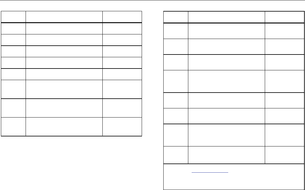
Pressure Calibrator
User-Replaceable Parts and Accessories
65
Item Description Part Number
TPAK80-4-8001 Strap, 9 in. 669960
Safety Sheet 4354604
Quick Reference Guide 4354567
User Manuals CD 4354598
AA, Alkaline Batteries 376756
Not
Shown
Bottom Plug, PRO 30,
150PSIG 4365560
Not
Shown 71X-TRAP, Liquid Dirt Trap 4380747
Not
Shown Test Lead Set Variable[1]
Item Description Part Number
Not
Shown Alligator Clip, Red Variable[1]
Not
Shown Alligator Clip, Black Variable[1]
Not
Shown RTD Probe 4366669
Not
Shown
URTDA, Universal RTD
Adapter (RTD Breakout Box)
for 719Pro and 721.
4382695
Not
Shown
Kit-hose, fittings (3), adapters
(2) 3345825
Not
Shown
FLK719PRO 300PRK, Pump
Rebuild Kit, 719PRO-300G 4401168
Not
Shown
FLK719PRO 30 150PR,
Pump Rebuild Kit, 719PRO-
30 AND 150G
4401179
Not
Shown
FLUKE-7XX Cable,USB, 5
Pin LEMO, SGL 6ft 4401616
[1] See www.fluke.com for more information about
the test leads and alligator clips available for your
region.
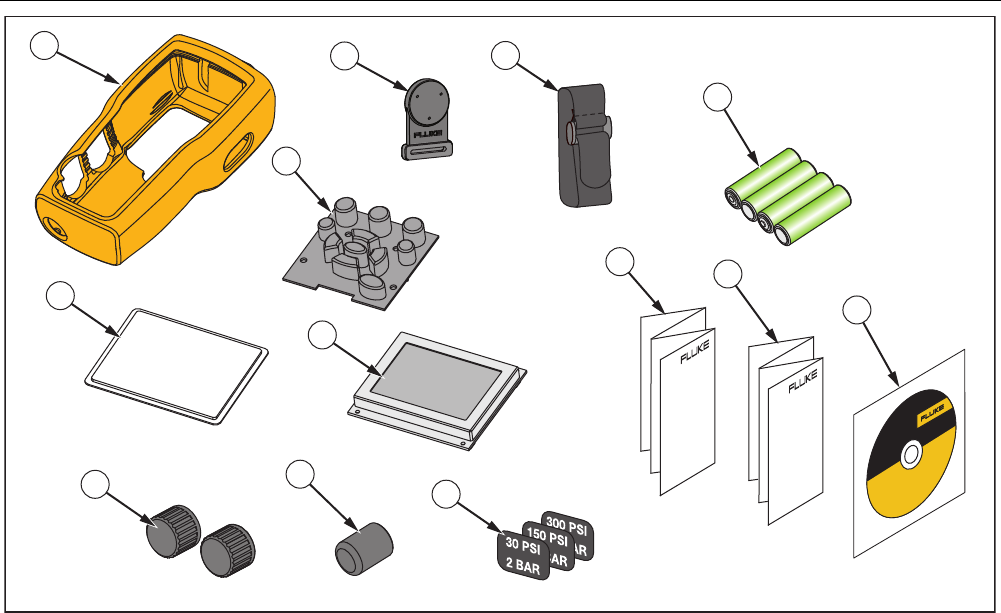
719PRO
Users Manual
66
1
11
10
12
8
2
3
4
57
6
9
13
hix063.eps
Figure 13. User-Replaceable Parts and Accessories

Pressure Calibrator
Specifications
67
Specifications
Pressure Measurement Range Resolution Accuracy Comment
719Pro-30G -12 to 30 PSI/-0.8 to
2 bar
0.001 PSI
0.0001 bar ±0.025 % of full scale,
6 months
±0.035 % of full scale,
1 year
Dry air and non-corrosive
gas only
719Pro-150G -12 to 150 PSI/-0.8 to
10 bar
0.01 PSI
0.001 bar
719Pro-300G -12 to 300 PSI/-0.8 to
20 bar
0.01 PSI
0.001 bar
Temperature effect (all
ranges)
Add ±0.002 % of full
scale for temps outside
of 15 °C to 35 °C
No effect on accuracy on
all functions from 15 °C
to 35 °C
Function Range Resolution Accuracy (1 year) Comment
mA dc
(simultation and
measurement)
0 mA dc to 24 mA dc 0.001 mA
±0.015 % of reading ±2
counts
1000 Ω maximum load in
mA source, 26 V dc
maximum voltage in mA
simulate
Volts dc
(measurement only) 30 V dc 0.001 V
No ac voltage
measurement, do not
exceed 30 V dc
Temperature
(measurement only,
Pt100 RTD)
-50 °C to 150 °C (-58 °F
to 302 °F)
0.01 °C
0.01 °F
Temperature ±0.1 °C
(0.2 °F)
±0.25 °C (±0.45 °F)
combined uncertainty
when using 720 RTD
probe (optional
accessory)
Loop power supply 24 V dc N/A 24 mA at 24 V
Temperature Effect (all
functions)
Add ±0.002 % full
scale/°C for temperatures
outside of 15 °C to 35 °C
No effect on accuracy on
all functions from 15 °C
to 35 °C

719PRO
Users Manual
68
Temperature Range
Operating .................................................. -10 °C to +50 °C (14 °F to +122 °F)
Storage
With Batteries ............................................ Per battery manufacturer’s specification, not to exceed storage specification without batteries.
Without Batteries ....................................... -20 °C to +60 °C (-4 °F to +140 °F)
Altitude .......................................................... 2000 m
Power
Batteries .................................................... 8 AA batteries (alkaline)
Battery Life ................................................ 300 pump cycles to 150 PSI minimum; 1000 pump cycles to 30 PSI; 100 pump cycles to
300 PSI minimum
Physical
Dimensions with holster ........................... (H x W x D) (24.13 x 11.18 x 7) cm, (9.5 x 4.4 x 2.8) in
Weight with holster ................................... 1.2 kg (2.5 lb)
Ingress Protection .................................... IP40
Connectors/Ports
Pressure ................................................... One (1), 1/8 in NPT
Electrical ................................................... Standard banana jacks
RTD Probe ................................................ 4-pin miniature circular
External Module ........................................ 6-pin miniature circular
Engineering Units ..................................... psi, bar, mbar, kPa, kgcm2, cmH2O @ 4 °C, cmH2O @ 20 °C, mH2O @ 4 °C, mH2O @ 20 °C,
inH2O @ 4 °C, inH2O @ 20 °C, inH2O @ 60 °F, mmHg @ 0 °C, inHg @ 0 °C, ftH2O @ 4 °C,
ftH2O @ 20 °C, ftH2O @ 60 °F

Pressure Calibrator
Specifications
69
Electromagnetic Environment ....................... IEC 61326-1: Portable
Electromagnetic Compatibility ....................... Applies to use in Korea only. Class A Equipment (Industrial Broadcasting & Communication
Equipment) [1]
[1] This product meets requirements for industrial (Class A) electromagnetic wave equipment
and the seller or user should take notice of it. This equipment is intended for use in business
environments and is not to be used in homes.

719PRO
Users Manual
70
