Fluke 753 Ing Application Note Process And Temperature Switch Applications With The 740 Series DPC
2015-09-09
: Fluke Fluke-753-ing-Application-Note-806002 fluke-753-ing-application-note-806002 fluke pdf
Open the PDF directly: View PDF ![]() .
.
Page Count: 5

Application Note
Process switches
A process switch is a device that
can sense a process variable —
such as temperature or pressure
— and change the state of one or
more sets of switch contacts
when that variable reaches a
predetermined value. This value
is called a setpoint. A switch can
have multiple setpoints. Let’s look
at some important concepts of
how process switches work.
Contacts. Contacts come in
pairs, and a pair is either nor-
mally open or normally closed.
“Normally” means without ener-
gization — just the way the
contacts would be on the shelf or
if you disconnected the power
wires from the switch.
Many process switches have
four sets of contacts — two
normally open and two normally
closed. But, there are many
variations. A single switch may
operate just one set of contacts,
or it may operate multiple sets
Process and temperature
switch applications with
the 740 Series DPCs
What about actuation? You
might want the switch to failsafe
upon loss of level in a cooling
tank. So, normal level would acti-
vate the switch (compared to its
shelf position). Upon loss of level,
the switch deactivate — that is, it
will assume the same state that
it would be in if it were on the
shelf. For an example of this
control logic, look at a typical
toggle-style light switch. You will
notice the word “ON” under the
toggle handle and the word OFF
above it. To reveal the word “ON,”
you must flip the switch up. If the
toggle mechanism were to fail
mechanically — which could
happen if, for example, it were to
melt due to arcing — the toggle
handle would drop into the “OFF”
position due to gravity. That is the
failsafe position of these switches.
It’s common to implement process
switches the same way.
Setpoint. A switch may have
multiple setpoints. For example,
many level switches come with
low-low, low, high, and high-
high sets of contacts — each with
its own setpoint.
But, it can get more complex
than that, depending on the
required control scheme and the
type of switch used. There are
many ways to accommodate
complex switching schemes —
including the use of an analog
transmitter serves as the input to
a virtual switch (implemented in
software).
From the Fluke Digital Library @ www.fluke.com/library
of normally open and normally
closed contacts. You select which
contacts to use based on the
desired output for a given condi-
tion and a given failsafe condition.
Control logic. You must think
of switch actuation and contact
state separately. Actuating the
typical process switch means
opening one set of contacts and
closing another at the same time.
Whether actuation opens or
closes a set of contacts depends
on whether you are using the
normally open or normally closed
contacts and whether the switch
is in an activated or deactivated
state during normal operation.
Failsafe operation is the first
criterion to assess when deciding
which set of contacts to use. For
example, you should use normally
closed contacts if breaking the
circuit will result in a failsafe
condition. Because loss of power
and an open circuit (via a broken
circuit wire, broken connection,
or intentional operation) have the
same effect on circuit operation,
the normally open contacts would
be the correct ones to use. Upon
loss of power, these contacts
will open. So, you would want
them to be closed for normal
operations and to open when
operations go into alarm or
control change conditions.
It is not true that, for example,
a high level switch will necessar-
ily close contacts when you reach
a high level condition. Good con-
trol practices usually dictate the
opposite.
This note discusses appli-
cations for process
switches and calibrating
temperature switches
using the Fluke 740 Series
Documenting Process
Calibrators (DPCs). Let’s
begin by looking at what a
process switch is and
what it does.
When you calibrate a high level
switch, you do so with the level
rising. This is standard practice
with all process variables, not
just level — you get a more accu-
rate calibration by accounting for
hysteresis.
Trip. This is the value at
which the switch will change the
state of a given set of contacts.
Where a switch trips is a function
of its setpoint and direction. For a
pressure switch with a setpoint
of 500 PSI, the switch should trip
at 500 PSI as pressure rises. Trip
is also called “set.” The opposite
of that is reset.
Reset. Some switches reset
automatically, while others
require a manual reset. In either
case, the reset will not occur until
the switch actuator has moved in
the direction opposite its trigger-
ing direction enough to overcome
hysteresis (and/or deadband —
see below) and allow the switch
to change contact states back to
normal. An exception to this is
when the switch is used to indi-
cate a normal condition. For such
switches, reset is usually not an
issue.
Hysteresis. This is the ten-
dency of the switch to stay in the
last position it was in. This
means that when you are cali-
brating a switch to trip at 500
PSI, the hysteresis of the switch
may cause it to trip at 501 PSI
when you are increasing pressure
and 499 PSI when you are
decreasing pressure. If this is a
high pressure switch (control
function requires a trip on rising
pressure), you would calibrate it
to trip at 500 PSI on an increas-
ing pressure input and let the
498 PSI trip serve as the maxi-
mum reset value.
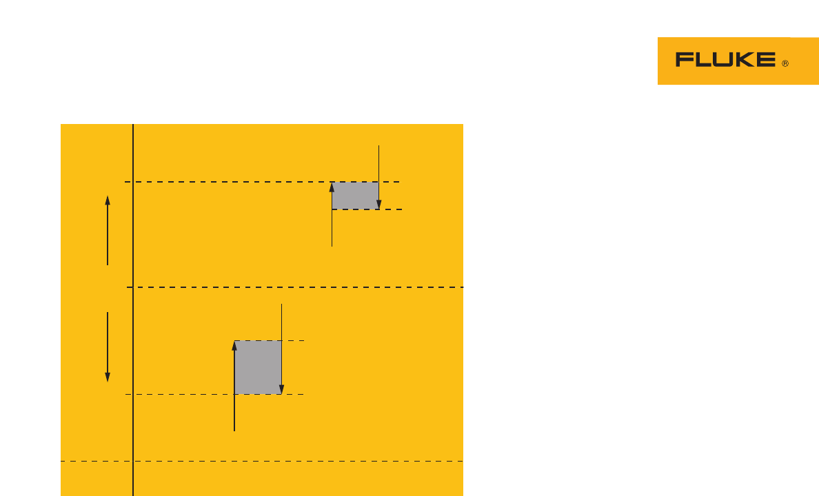
Band.This is the area around
the setpoint where the switch is
controlling the process. For exam-
ple, if the switch will control a
tank to maintain a level between
6 feet of water and 9 feet of
water, it has a band of 3 feet.
Deadband
Open
High Limit
Process
Variable
Low Limit
Setpoint
Reset
Closed
50 °C
20 °C
Deadband
Closed
Reset
Setpoint
Open
Figure 1. 2-point switch with settings for low and high setpoints.
2 Fluke Corporation Process and temperature switch applications with the 740 Series DPCs
Here’s an example of a com-
plex application. A level switch
may allow a “normal” indication
(such as a light) to display at any
level up to 82 %. At 82 %, the
switch causes normal indication
to go off — placing the indication
between a normal state and an
alarm state. At 85 %, the switch
may trigger a high level alarm
light. At 90 %, the switch may
trigger a high-high level alarm
light plus an audio alarm. At
93 %, it may trigger a feed valve
closure. At 95 %, it may trigger
dump valve operation. At 97 %,
it may trigger drain pump opera-
tion. At 98 %, it may actuate
isolation doors in the room con-
taining the tank. And those
actions are just for high level.
This same switch, or another,
might control low level opera-
tions. In some configurations, you
might have separate switches for
each setpoint.
Setpoint tolerance. This is
the amount of error you can have
between the desired setpoint and
the one you actually set. It’s not
always easy to calibrate a switch
directly on the desired setpoint —
for a variety of reasons. For
example, if you must open a
valve when the temperature
reaches 313 degrees, your set-
point tolerance might allow you
consider the switch calibrated if
it trips within 5 degrees of the
setpoint. Tolerances may be
expressed in engineering units or
in percent. When expressed in
percent, that normally means
percent of the control band (we
explain band below), not in per-
cent of the setpoint value.
Direction. Switch actuation
(and, therefore, control) is direc-
tional, due to hysteresis.
Sometimes, the hysteresis value
can exceed the setpoint toler-
ance. For non-critical applications
with wide setpoint tolerances,
you can probably ignore hystere-
sis. But, standard practice is to
observe direction when calibrat-
ing a setpoint. When you
calibrate a low level switch, you
do so with the level dropping.
Deadband. This is closely
related to reset. Deadband pre-
vents a switch from cycling
around a setpoint. Hysteresis pro-
vides some deadband,
automatically. But for some
processes, hysteresis is not
enough to prevent undesirable
on/off cycling. So, many switches
have additional deadband inten-
tionally designed into them. That
deadband may be fixed, fixed
selectable, or variable. For exam-
ple, an electronic thermostat used
for a heat pump may have a fixed
selectable deadband of 1.5
degrees or 3 degrees.
Range. This is specified with
the low and high points of opera-
tion. For example, if the switch
will control a tank to maintain a
level between 6 feet of water
and 9 feet of water, it has a cali-
bration range of 6 to 9 feet. The
switch itself might have an actual
range of 0 to 50 feet — this range
would appear on the nameplate
of the switch.
Testing a temperature
switch
The switch in the following
example is a temperature switch
with a type K thermocouple input
and a low temperature setpoint of
20 °C. This switch functions in
much the same way as the ther-
mostat in your home. The Low
Limit example in Figure 1 illus-
trates the terminology.
We will be using the normally
open contacts of this switch.
These contacts will close upon
switch actuation, which will
occur with a drop in temperature.
This switch does not have
adjustable reset. The contacts
will re-open upon automatic
reset, which occurs as the tem-
perature moves back up and past
the setpoint in an amount greater
than its deadband. The deadband
is a minimum of 1 °C and maxi-
mum of 3 °C across the range of
the switch.
To set up the Fluke 740 Series
DPC to calibrate the switch,
follow these step-by-step instruc-
tions. Keystroke entries for the
DPC are surrounded by quotation
marks.
1. Beginning in the power up
state of the calibrator, or
Measure mode, depress the
“ohms/continuity” key twice
to enable continuity mode.
2. Simulate the temperature
input.
a. Depress the
“MEAS/SOURCE” key
once to obtain the
Source mode.
b. Depress the “TC/RTD”
key, move the cursor with
the “↓” key to “K” and
depress “ENTER” to select
a type K thermocouple.
c. Depress “ENTER” again to
select “Linear T.”
d. Enter a temperature out-
put of “25” and depress
“ENTER.”
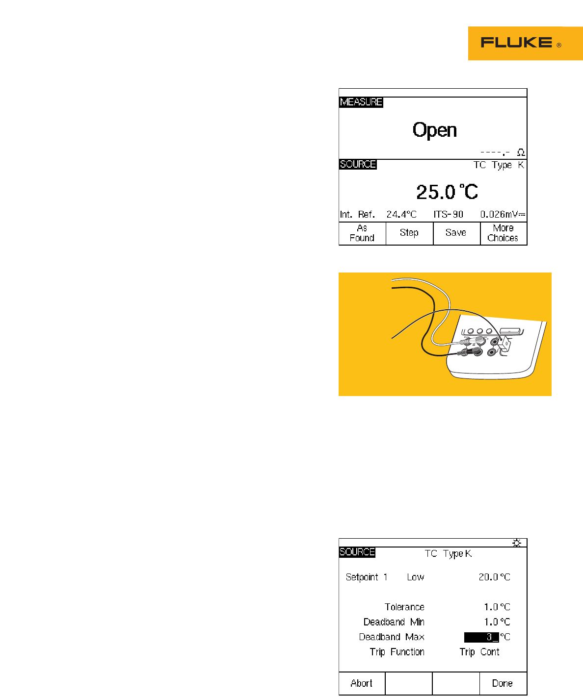
e. Depress the
“MEAS/SOURCE” key to
obtain the split screen
display. The display of the
74X should be as per
Figure 2.
3. Connect the DPC, per
Figure 3.
4. Take As Found
measurements.
a. Select the “As Found”
softkey.
b. Move the cursor to “1 Pt.
c. Switch Test” with the “↓”
key and depress “ENTER.”
You should now see the
switch test setup screen.
5. Enter the setpoint.
a. Depress “Enter” and enter
a setpoint of “20” °C, then
depress “ENTER” again.
The Setpoint Type is set
for low and the Set State
is a short by default —
perfect for this particular
test. (If these conditions
were different, we would
change them here.).
These setup conditions
describe a switch that has
a setpoint of 20 °C and
closes a set of contacts as
long as the input temper-
ature to the switch is
below 20 °C.
b. Depress the “Done”
softkey.
6. Enter the setpoint tolerance and deadband
settings.
a. Move the cursor to tolerance and enter a
setpoint tolerance of “1” °C.
b. Move the cursor to Deadband Min and
enter a minimum deadband of “1” °C.
c.Move the cursor to Deadband Max and
enter a maximum deadband value of 3 °C.
The test setup screen should now be as
per Figure 4. Depress the “Done” softkey.
Figure 2. MEASURE/SOURCE split screen, contacts open.
ENTER
V
RTD
MEAS
SOURCE
mA mA
RTD
V
300V
MAX
30V MAX
TC
Fluke 741/743
To Limit
Switch Contacts
To Limit Switch
Thermocouple
Input
Figure 3. Connecting the DPC.
Figure 4. Test setup screen.
3 Fluke Corporation Process and temperature switch applications with the 740 Series DPCs
8. Enter Tag information.
a. Depress the “Done” soft-
key and enter the Tag
information for your test.
b. Depress the “Done” soft-
key when tag entry is
complete.
9. Adjust setpoints or reset
points.
a. If the switch failed any of
the test parameters, it is
necessary to adjust the
set and/or reset points. To
do that, first select the
“adjust” softkey.
b. Depress the “Step Size”
softkey, then enter a step
size of “.1” °C.
c. Depress the “Done”
softkey.
d. Depress the “↓” key until
the DPC source value is
20 °C (the setpoint).
e. Slowly adjust the setpoint
on the limit switch until
the measure screen tog-
gles from reset to set.
Depress the “↑” key until
the DPC measure screen
toggles to Reset. If the
DPC toggles from set to
reset between 21 °C and
23 °C, the deadband
should be correctly set.
If it does not toggle prop-
erly, adjust the reset point
until it toggles within that
band.
f. Verify the set and reset
points toggle correctly, by
depressing the “↓” and
“↑” keys to slew the DPC
source temperature across
the set and reset values.
g. Once that is complete,
depress the
“Done”
softkey.
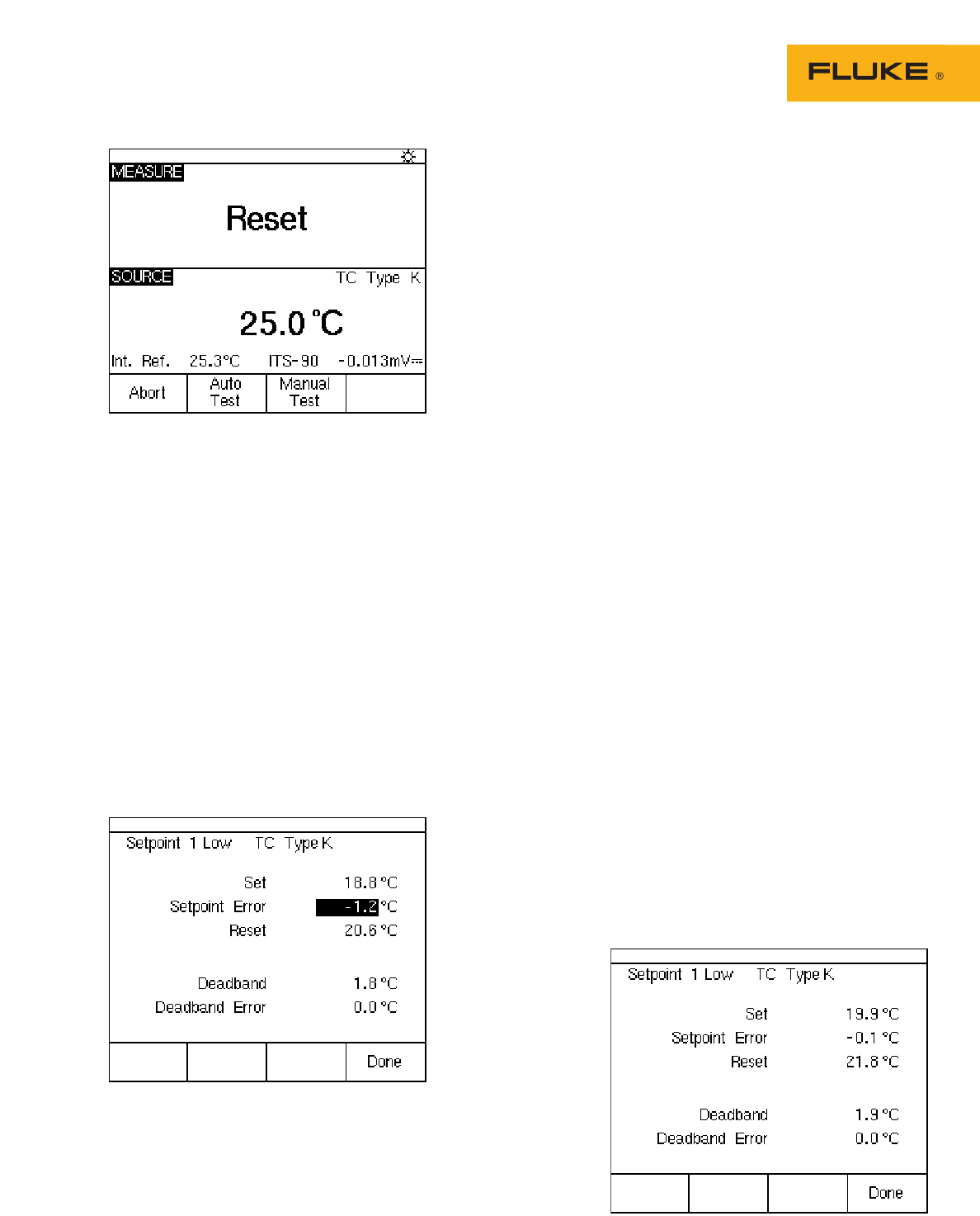
Figure 5. MEASURE/SOURCE split screen, contacts reset.
7. You should now see the split screen
(Figure 5). Select the “Auto Test” softkey
and the “Continue” softkey. The DPC will
now ramp the simulated thermocouple
potential into the limit switch back and
forth past the nominal setpoint and record
the sourced temperature values for the
actual setpoint, and then show that value
in the upper left-hand corner of the DPC
display. Once that is done, the DPC will
then test the reset point of the switch by
ramping the simulated thermocouple
potential into the switch back and forth
past the nominal (21 °C - 23 °C) expected
reset value. Once that value is recorded,
you should be presented with a post test
summary similar to that in Figure 6. Errors
exceeding test tolerance are recorded in
inverse video.
Figure 6. Post-test summary, with reverse video.
Figure 7. Post-test summary, with all results normal.
10. Confirm the As Left settings.
a. Depress the “As Left”
softkey.
b. Confirm the test settings.
c. Depress the “Done”, “Auto
Test” and “Continue” soft-
keys. Monitor the DPC as
it performs the As Left
evaluation.
d. Once the post test sum-
mary is displayed, review
the results. If all results
are in normal video (as in
Figure 7), the As Left test
passes.
e. Depress the “Done” soft-
key, and “D ne” again to
save the Tag information.
f. If there were inverse
video indications of a fail-
ure, repeat the
adjustments performed in
Step 9 until a passing
result is obtained.
11. Review results in memory,
a. Depress the “Done”
and “Review Memory”
softkeys.
b. Move the cursor to the tag
entry associated with this
test and depress “ENTER.”
c. Move the cursor to the As
Found entry and depress
“Enter” to review your As
Found result.
d. Depress the “Done”
softkey.
e. Move the cursor to the As
Left entry and depress
“Enter” to review that
result.
f. Depress the “Done” soft-
key, then depress the
“Tag” softkey to review
your Tag information.
4 Fluke Corporation Process and temperature switch applications with the 740 Series DPCs

Other switch tests
In the preceding step by step
description, the switch has been
removed from its operational cir-
cuit and the switch contact
closure is monitored to determine
state change.
You can perform this test with
the switch installed in its circuit.
In this instance, the switch con-
tacts will open and close and you
can use the 740 Series DPC to
measure the presence or absence
of system voltage (e.g. 120VAC) as
switch contacts change state. A
typical example would be measur-
ing the voltage applied to a
heater as controlled by the output
of the switch. The 740 series
DPCs can work with dc voltage in
addition to the continuity and ac
voltage examples previously
described.
Our examples in this applica-
tion note have been for
temperature switches. The 740
series DPCs allow you to test
pressure switches, too — in fact,
in 11 different engineering units.
Pressure switch tests are similar
to temperature switch tests — you
vary the process variable (source)
at the input, and monitor for a
change of state at the output. You
need to use a hand pump to
source pressure into a pressure
module and the switch. You can
manually document the results
by depressing the “Accept Point”
soft key when the test has been
completed.
With the 740 series DPCs, you
can source and measure many
key variables. And these tools are
useful for calibrating any process
switch. Of course, you will need
to supply your own inputs for
many types of process variables —
such as level, flow, and pH. The
principles of switch operation out-
lined here apply universally.
Fluke Corporation
PO Box 9090, Everett, WA USA 98206
Fluke Europe B.V.
PO Box 1186, 5602 BD
Eindhoven, The Netherlands
For more information call:
In the U.S.A. (800) 443-5853 or
Fax (425) 446-5116
In Europe/M-East/Africa (31 40) 2 675 200 or
Fax (31 40) 2 675 222
In Canada (800) 36-FLUKE or
Fax (905) 890-6866
From other countries +1 (425) 446-5500 or
Fax +1 (425) 446-51
16
Web access: http://www.fluke.com
©2004 Fluke Corporation. All rights reserved.
Printed in U.S.A. 7/2004 1263879 A-US-N Rev D
Fluke. Keeping your world
up and running.
For detailed information on
calibrating pressure switches,
reference Fluke Application
Note 2069058.
5 Fluke Corporation Process and temperature switch applications with the 740 Series DPCs
