Fluke 754 Ing Users Manual
2015-09-09
: Fluke Fluke-754-ing-Users-Manual-806351 fluke-754-ing-users-manual-806351 fluke pdf
Open the PDF directly: View PDF ![]() .
.
Page Count: 52
- 753/754 Calibration Manual
- Introduction
- How to Contact Fluke
- Safety Information
- Symbols
- Specifications
- General Specifications
- Detailed Specifications
- DC mV Measurement
- DC Voltage Measurement
- AC Voltage Measurement
- DC Current Measurement
- Resistance Measurement
- Continuity Testing
- Frequency Measurement
- ±DC Voltage Output
- +DC Current Source
- +DC Current Simulate (External Loop Power)
- Resistance Sourcing
- Frequency Sourcing
- Temperature, Thermocouples
- Temperature, Resistance Temperature Detectors
- Loop Power
- Performance Verification Tests
- Verification Equipment
- How to Verify
- DC Volts Measurement
- AC Volts Measurement
- DC Current Measurement
- Resistance Measurement
- Frequency Measurement
- DC Volts Source
- DC Current Source
- Simulate Transmitter Function
- Resistance Source Function
- Frequency Source
- Thermocouple Measure
- Thermocouple Source
- RTD Measure, Four-Wire
- RTD Measure, Three-Wire
- RTD Source
- Loop Power
- HART Mode Verification (754 Only)
- Calibration
- Static Awareness
- Maintenance
- Replaceable Parts
- Accessories

November 2011
© 2011 Fluke Corporation. All rights reserved. Printed in USA. Specifications are subject to change without notice.
All product names are trademarks of their respective companies.
753/754
Documenting Process Calibrator
Calibration Manual
LIMITED WARRANTY AND LIMITATION OF LIABILITY
Each Fluke product is warranted to be free from defects in material and workmanship under normal use and
service. The warranty period is three years and begins on the date of shipment. Parts, product repairs, and
services are warranted for 90 days. This warranty extends only to the original buyer or end-user customer of
a Fluke authorized reseller, and does not apply to fuses, disposable batteries, or to any product which, in
Fluke's opinion, has been misused, altered, neglected, contaminated, or damaged by accident or abnormal
conditions of operation or handling. Fluke warrants that software will operate substantially in accordance
with its functional specifications for 90 days and that it has been properly recorded on non-defective media.
Fluke does not warrant that software will be error free or operate without interruption.
Fluke authorized resellers shall extend this warranty on new and unused products to end-user customers
only but have no authority to extend a greater or different warranty on behalf of Fluke. Warranty support is
available only if product is purchased through a Fluke authorized sales outlet or Buyer has paid the
applicable international price. Fluke reserves the right to invoice Buyer for importation costs of
repair/replacement parts when product purchased in one country is submitted for repair in another country.
Fluke's warranty obligation is limited, at Fluke's option, to refund of the purchase price, free of charge repair,
or replacement of a defective product which is returned to a Fluke authorized service center within the
warranty period.
To obtain warranty service, contact your nearest Fluke authorized service center to obtain return
authorization information, then send the product to that service center, with a description of the difficulty,
postage and insurance prepaid (FOB Destination). Fluke assumes no risk for damage in transit. Following
warranty repair, the product will be returned to Buyer, transportation prepaid (FOB Destination). If Fluke
determines that failure was caused by neglect, misuse, contamination, alteration, accident, or abnormal
condition of operation or handling, including overvoltage failures caused by use outside the product’s
specified rating, or normal wear and tear of mechanical components, Fluke will provide an estimate of repair
costs and obtain authorization before commencing the work. Following repair, the product will be returned to
the Buyer transportation prepaid and the Buyer will be billed for the repair and return transportation charges
(FOB Shipping Point).
THIS WARRANTY IS BUYER'S SOLE AND EXCLUSIVE REMEDY AND IS IN LIEU OF ALL OTHER
WARRANTIES, EXPRESS OR IMPLIED, INCLUDING BUT NOT LIMITED TO ANY IMPLIED WARRANTY
OF MERCHANTABILITY OR FITNESS FOR A PARTICULAR PURPOSE. FLUKE SHALL NOT BE LIABLE
FOR ANY SPECIAL, INDIRECT, INCIDENTAL OR CONSEQUENTIAL DAMAGES OR LOSSES,
INCLUDING LOSS OF DATA, ARISING FROM ANY CAUSE OR THEORY.
Since some countries or states do not allow limitation of the term of an implied warranty, or exclusion or
limitation of incidental or consequential damages, the limitations and exclusions of this warranty may not
apply to every buyer. If any provision of this Warranty is held invalid or unenforceable by a court or other
decision-maker of competent jurisdiction, such holding will not affect the validity or enforceability of any other
provision.
Fluke Corporation
P.O. Box 9090
Everett, WA 98206-9090
U.S.A.
Fluke Europe B.V.
P.O. Box 1186
5602 BD Eindhoven
The Netherlands
11/99
i
Table of Contents
Title Page
Introduction ........................................................................................................ 1
How to Contact Fluke ........................................................................................ 1
Safety Information ............................................................................................. 2
Symbols ............................................................................................................. 3
Specifications ..................................................................................................... 4
General Specifications ....................................................................................... 4
Environmental Specifications ........................................................................ 4
Standards and Agency Approval Specifications ........................................... 4
Detailed Specifications ...................................................................................... 4
DC mV Measurement .................................................................................... 4
DC Voltage Measurement ............................................................................. 5
AC Voltage Measurement ............................................................................. 5
DC Current Measurement .............................................................................. 5
Resistance Measurement ............................................................................... 5
Continuity Testing ......................................................................................... 5
Frequency Measurement ............................................................................... 6
±DC Voltage Output ...................................................................................... 6
+DC Current Source ...................................................................................... 6
+DC Current Simulate (External Loop Power) ............................................. 6
Resistance Sourcing ....................................................................................... 6
Frequency Sourcing ....................................................................................... 7
Temperature, Thermocouples ........................................................................ 7
Temperature, Resistance Temperature Detectors .......................................... 8
Loop Power ................................................................................................... 8
Performance Verification Tests ......................................................................... 9
Verification Equipment ................................................................................. 9
How to Verify ................................................................................................ 10
DC Volts Measurement ............................................................................. 10
AC Volts Measurement ............................................................................. 12
DC Current Measurement ......................................................................... 13
Resistance Measurement ........................................................................... 14
Frequency Measurement ........................................................................... 16
DC Volts Source ....................................................................................... 17
DC Current Source .................................................................................... 18
Simulate Transmitter Function .................................................................. 19
Resistance Source Function ...................................................................... 20

753/754
Calibration Manual
ii
Frequency Source ...................................................................................... 21
Thermocouple Measure ............................................................................. 23
Thermocouple Source ............................................................................... 25
RTD Measure, Four-Wire ......................................................................... 26
RTD Measure, Three-Wire ....................................................................... 27
RTD Source ............................................................................................... 29
Loop Power ............................................................................................... 30
HART Mode Verification (754 Only) ............................................................... 30
Calibration ......................................................................................................... 32
Equipment Required for Calibration ............................................................. 32
Calibration Status Indicator ........................................................................... 32
How to Enter Calibration ............................................................................... 32
Calibration Constant Out of Bounds ............................................................. 33
How to Calibrate ....................................................................................... 33
Maintenance ....................................................................................................... 35
Battery Replacement ..................................................................................... 35
How to Clean the Product .............................................................................. 35
Calibration Data ............................................................................................. 36
In Case of Difficulty ...................................................................................... 36
Service Center Calibration or Repair ............................................................. 36
Replaceable Parts ............................................................................................... 37
Accessories ........................................................................................................ 41
iii
List of Tables
Table Title Page
1. Symbols .................................................................................................................. 3
2. Equipment Required for Verification ..................................................................... 9
3. DC Volts Measurement Verification Points ........................................................... 11
4. AC Volts Measurement Verification Points ........................................................... 12
5. DC Current Measurement Verification Points ....................................................... 14
6. Resistance Measurement Verification Points ......................................................... 15
7. Frequency Measurement Verification Points ......................................................... 16
8. DC Volts Source Verification Points ..................................................................... 17
9. DC Current Source Verification Points .................................................................. 18
10. Simulate Transmitter Verification Points ............................................................... 20
11. Resistance Source Verification Points ................................................................... 21
12. Frequency Source Verification Points .................................................................... 22
13. Temperature Measure Verification ........................................................................ 25
14. Temperature Source Verification (Type-K Thermocouple, ITS-90) ..................... 26
15. RTD Measure Verification (100W Pt (385), Four-Wire Connection) ................... 27
16. RTD Measure Verification (100W Pt (385), Three-Wire Connection) ................. 28
17. RTD Source Verification (100W Pt (385)) ............................................................ 29
18. Replacement Parts .................................................................................................. 37
19. Accessories ............................................................................................................. 41

753/754
Calibration Manual
iv
v
List of Figures
Figure Title Page
1. DC Volts and AC Volts Measurement Connections .............................................. 11
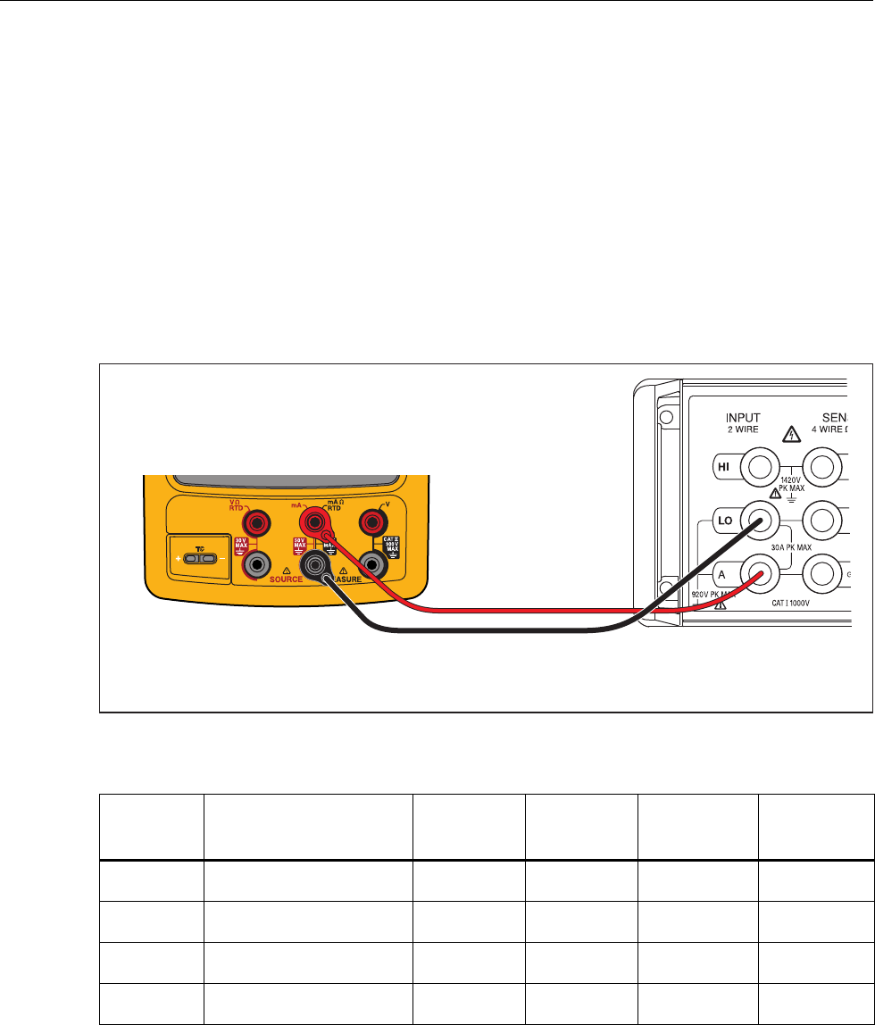
2. DC Current Measurement Verification Connections ............................................. 13
3. Resistance Measurement Verification Connections ............................................... 15
4. Frequency Measurement Verification Connections ............................................... 16
5. DC Volts Source Verification Connections ........................................................... 17
6. DC Current Source Verification Connections ........................................................ 18
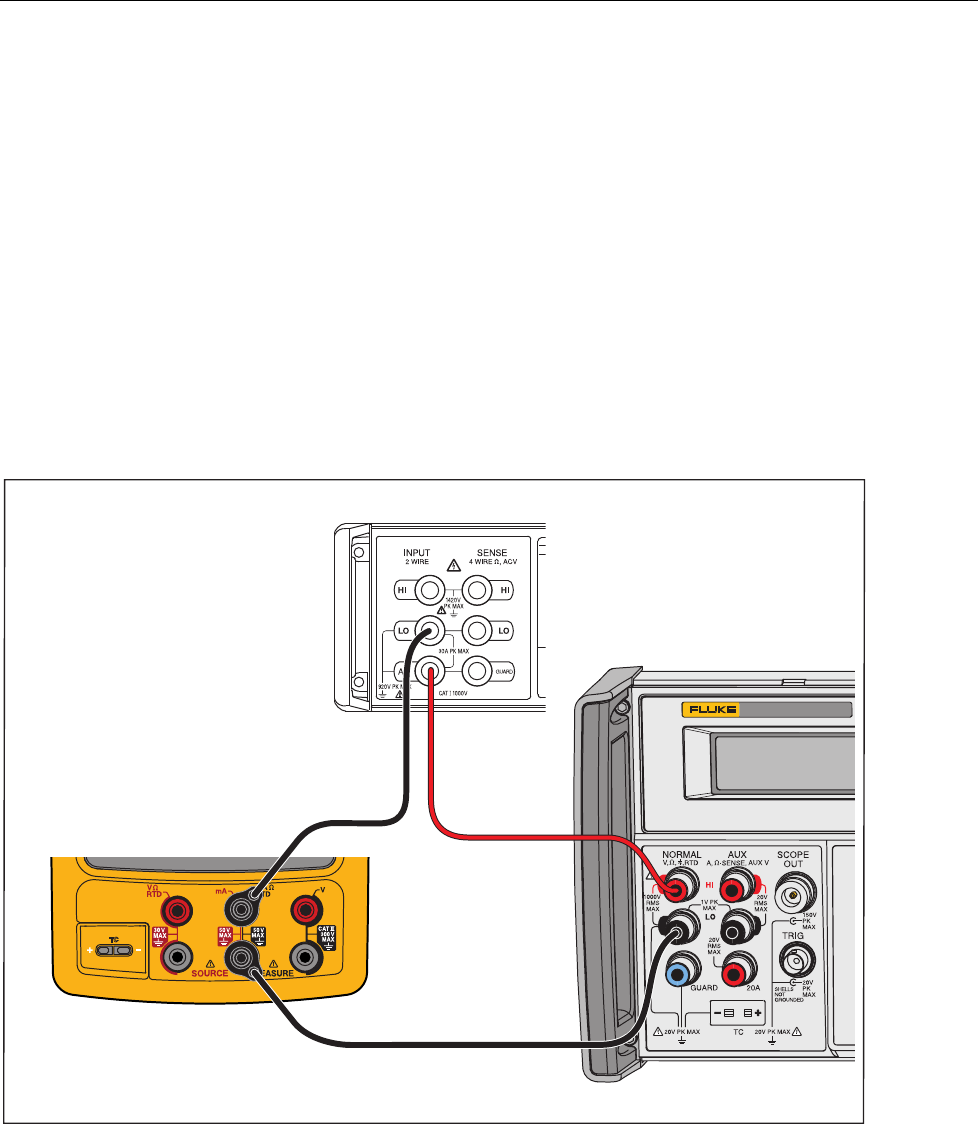
7. Simulate Transmitter Verification Connections ..................................................... 19
8. Resistance Source Verification Connections ......................................................... 20
9. Frequency Source Verification Connections .......................................................... 22
10. Temperature Measure (TC) Verification Connections ........................................... 24
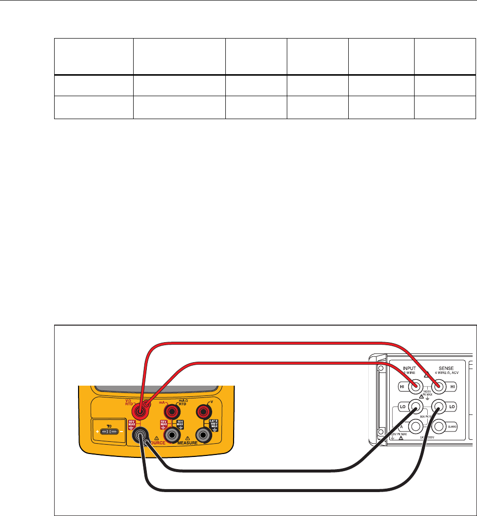
11. Four-Wire RTD Measure Verification Connections .............................................. 27
12. Three-Wire RTD Measure Verification Connections ............................................ 28
13. Loop Power Verification Connections ................................................................... 30
14. Active Device Screen ............................................................................................. 31
15. HART Mode Verification Connections ................................................................. 32
16. Parts ........................................................................................................................ 40

753/754
Calibration Manual
vi

1
Introduction
This manual contains data necessary to do performance verification tests and calibration
adjustments on your 753 and 754 Documenting Process Calibrators (the Product).
How to Contact Fluke
To contact Fluke, call one of the following telephone numbers:
• Technical Support USA: 1-800-44-FLUKE (1-800-443-5853)
• Calibration/Repair USA: 1-888-99-FLUKE (1-888-993-5853)
• Canada: 1-800-36-FLUKE (1-800-363-5853)
• Europe: +31 402-675-200
• Japan: +81-3-6714-3114
• Singapore: +65-738-5655
• Anywhere in the world: +1-425-446-5500
Or, visit Fluke’s website at www.fluke.com
To register your product, visit http://register.fluke.com
To view, print, or download the latest manual supplement, visit
http://us.fluke.com/usen/support/manuals
The latest software trial version of DPCTrack2 can be downloaded at
www.fluke.com/DPCTrack . For more information see “Communication with a PC”.
753/754 Accessories can be found at www.fluke.com/process_acc

753/754
Calibration Manual
2
Safety Information
A Warning identifies condition and procedures that are dangerous to the user. A Caution
identifies conditions and procedures that can cause damage to the Product or the
equipment under test.
XW Warning
To prevent personal injury, use the Product only as
specified, or the protection supplied by the Product can be
compromised.
To prevent possible electrical shock, fire, or personal injury:
• Read all safety Information before you use the
Product.
• Carefully read all instructions.
• Use only correct measurement category (CAT),
voltage, and amperage rated probes, test leads, and
adapters for the measurement.
• The battery must be locked in place before you
operate the Product.
• Recharge the battery when the low battery indicator
shows to prevent incorrect measurements.
• Do not apply more than the rated voltage, between the
terminals or between each terminal and earth ground.
• Limit operation to the specified measurement
category, voltage, or amperage ratings.
• Do not exceed the Measurement Category (CAT)
rating of the lowest rated individual component of a
Product, probe, or accessory.
• Measure a known voltage first to make sure that the
Product operates correctly.
• Do not touch voltages > 30 V ac rms, 42 V ac peak, or
60 V dc.
• Do not use the Product around explosive gas, vapor,
or in damp or wet environments.
• Do not use, and disable the Product if it is damaged.
• Do not use the Product if it operates incorrectly.
• Keep fingers behind the finger guards on the probes.
• Remove all probes, test leads, and accessories that
are not necessary for the measurement.
• Only use probes, test leads, and accessories that
have the same measurement category, voltage, and
amperage ratings as the Product.

Documenting Process Calibrator
Symbols
3
• Connect the common test lead before the live test
lead and remove the live test lead before the common
test lead.
• Use only current probes, test leads, and adapters
supplied with the Product.
• Do not touch the probes to a voltage source when the
test leads are connected to the current terminals.
• Use only cables with correct voltage ratings.
• Do not use test leads if they are damaged. Examine
the test leads for damaged insulation, exposed metal,
or if the wear indicator shows. Check test lead
continuity.
• Examine the case before you use the Product. Look
for cracks or missing plastic. Carefully look at the
insulation around the terminals.
Symbols
Symbols used on the Product and in this manual are shown in Table 1.
Table 1. Symbols
Symbol Meaning Symbol Meaning
JEarth ground ˜Common (LO) Input
equipotentiality
AC- alternating current )Conforms to relevant North
American Safety Standards.
DC- direct current PConforms to European Union
directives.
WRisk of danger. Important
information. See manual. fPressure
XHazardous voltage. Risk of
electrical shock. ~
Do not dispose of this product as
unsorted municipal waste. Go to
Fluke’s website for recycling
information.
,Application around and removal
from HAZARDOUS LIVE
conductors is permitted.
Conforms to relevant Australian
standards.
TDouble insulated ®German certifying body.
CAT II
CAT II equipment is designed to protect against transients from energy-consuming
equipment supplied from the fixed installation, such as TVs, PCs, portable tools, and
other household appliances.

753/754
Calibration Manual
4
Specifications
General Specifications
All specifications apply from +18 °C to +28 °C unless stated otherwise.
All specifications assume a 5-minute warmup period.
Measurement specifications are valid only when Damping is turned on. When damping is turned off, or when the
gannunciator is shown, floor specifications are multiplied by 3. Floor specifications are the second part of the
specifications. The measure pressure, temperature, and frequency functions are specified only with damping on.
Specifications are valid to 110 % of range. The following exceptions are valid to 100 % of range: 300 V dc, 300 V ac,
22 mA source and simulate, 15 V dc source, and temperature measure and source.
To achieve the best noise rejection, use battery power.
Size (H x W x L) ..................................................................... Height = 63.35 mm (2.49 inches) x Width =
136.37 mm (5.37 inches) x Length = 244.96 mm
(9.65 inches)
Weight .................................................................................... 1.23 kg (2.71 lb) (Batteries included)
Display ................................................................................... 480 by 272 pixel graphic LCD, 95 x 54 mm
Power ..................................................................................... Internal battery pack: Lithium Ion, 7.2 V dc, 30 Wh
Environmental Specifications
Operating Altitude ................................................................. 3000 m (9842 ft)
Storage Altitude .................................................................... 13000 m (42650 ft)
Operating Temperature ........................................................ -10 to 50 °C
Storage Temperature ........................................................... -20 to 60 °C
Relative Humidity (Maximum, non-condensing) ................ 90 % to 35 °C
75 % to 40 °C
45 % to 50 °C
Standards and Agency Approval Specifications
Protection Class .................................................................... Pollution Degree II IP 52
Double Insulation Creepage and Clearance ....................... Per IEC 61010-1
Installation Category ............................................................ 300 V CAT II
Design Standards and Compliance .................................... EN/IEC 61010-1:2010, CAN/CSA C22.2 No. 61010-1-04,
ANSI/UL 61010-1:2004
EMI, RFI, EMC ........................................................................ EN 61326-1:2006
RF Fields ................................................................................ Accuracy for all functions is not specified in RF fields >3 V/m
Detailed Specifications
Specifications valid after a 5-minute warmup.
Specifications are valid to 110 % of Range with the following exceptions: 300 V dc measure, 300 V ac measure, 50 kHz
measure and source, 22 mA source and simulate, 15 V dc source, and temperature measure and source which are valid
to 100 % of range.
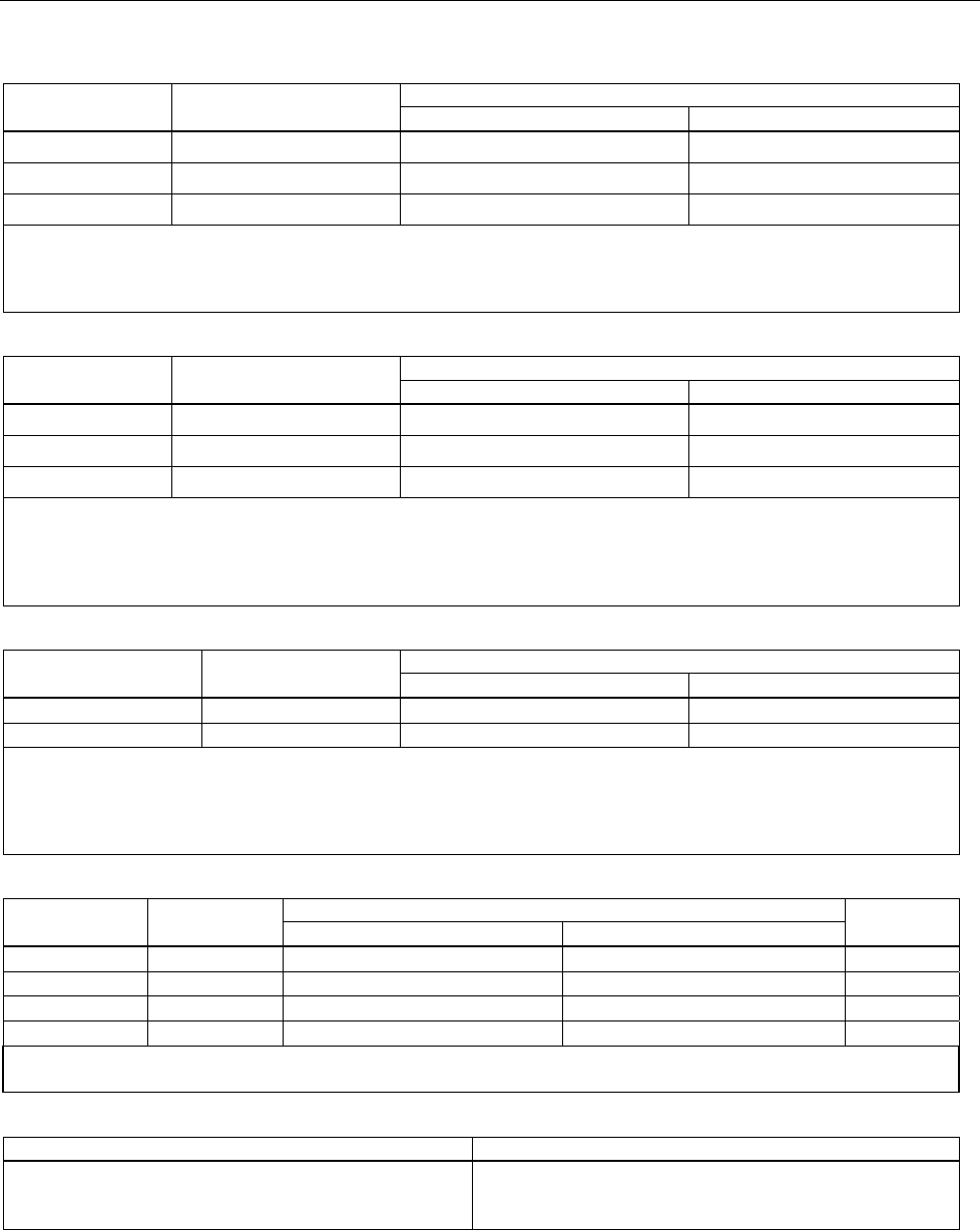
DC mV Measurement
Range Resolution % of Reading + Floor
1-Year 2 Year
±100.000 mV 0.001 mV 0.02 % + 0.005 mV 0.03 % + 0.005 mV
Input Impedance: >5 MΩ
Maximum Input Voltage: 300 V, IEC 61010 300 V CAT II
Temperature coefficient: (0.001 % of reading + 0.001% of range) / °C (<18 °C or >28 °C)
Normal mode rejection: >100 dB at 50 or 60 Hz nominal
Documenting Process Calibrator
Detailed Specifications
5
DC Voltage Measurement
Range Resolution % of Reading + Floor
1-Year 2 Year
±3.00000 V 0.00001 V 0.02 % + 0.00005 V 0.03 % + 0.00005 V
±30.0000 V 0.0001 V 0.02 % + 0.0005 V 0.03 % + 0.0005 V
±300.00 V 0.01 V 0.05 % + 0.05 V 0.07 % + 0.05 V
Input Impedance: >4 MΩ
Maximum Input Voltage: 300 V, IEC 61010 300V CAT II
Temperature coefficient: (0.001 % of reading + 0.0002 % of range) / °C (<18 °C or >28 °C)
Normal mode rejection: >100 dB at 50 or 60 Hz nominal
AC Voltage Measurement
Range
40 Hz – 500 Hz Resolution % of Reading + Floor
1-Year 2 Year
3.000 V 0.001 V 0.5 % + 0.002 V 1.0 % + 0.004 V
30.00 V 0.01 V 0.5 % + 0.02 V 1.0 % + 0.04 V
300.0 V 0.1 V 0.5 % + 0.2 V 1.0 % + 0.2 V
Input Impedance: >4 M Ω and <100 pF
Input Coupling: AC
Maximum Input Voltage: 300 V, IEC 61010 300V CAT II
Temperature coefficient: 5 % of specified accuracy / °C (<18 °C or >28 °C)
Specifications apply for 9 % to 100 % of voltage range.
DC Current Measurement
Range Resolution % of Reading + Floor
1-Year 2 Year
±30.000 mA 1 μA 0.01 % + 5 μA 0.015 % + 7 μA
±100.00 mA 10 μA 0.01 % + 20 μA 0.015 % + 30 μA
Maximum Input: 110 mA
Maximum Burden Voltage: 420 mV at 22 mA
Temperature coefficient: 3 % of specified accuracy / °C (<18 °C or >28 °C)
No Fuse
Normal mode rejection: 90 dB at 50 or 60 Hz nominal, and 60 dB at 1200 Hz and 2200 Hz nominal (HART signals)
Resistance Measurement
Range Resolution % of Reading + Floor Source
Current
1-Year 2 Year
10.000 Ω 0.001 Ω 0.05 % + 0.050 Ω 0.07 % + 0.070 Ω 3 mA
100.00 Ω 0.01 Ω 0.05 % + 0.05 Ω 0.07 % + 0.07 Ω 1 mA
1.0000 kΩ 0.1 Ω 0.05 % + 0.0005 kΩ 0.07 % + 0.0007 kΩ 500 μA
10.000 kΩ 1 Ω 0.10 % + 0.010 kΩ 0.15 % + 0.015 kΩ 50 μA
Open-circuit voltage: 5 V nominal
Temperature coefficient: 3 % of specified accuracy / °C (<18 °C or >28 °C)
Continuity Testing
Tone Resistance
Continuous tone
May or may not get tone
No tone
<25 Ω
25 to 400 Ω
>400 Ω
753/754
Calibration Manual
6
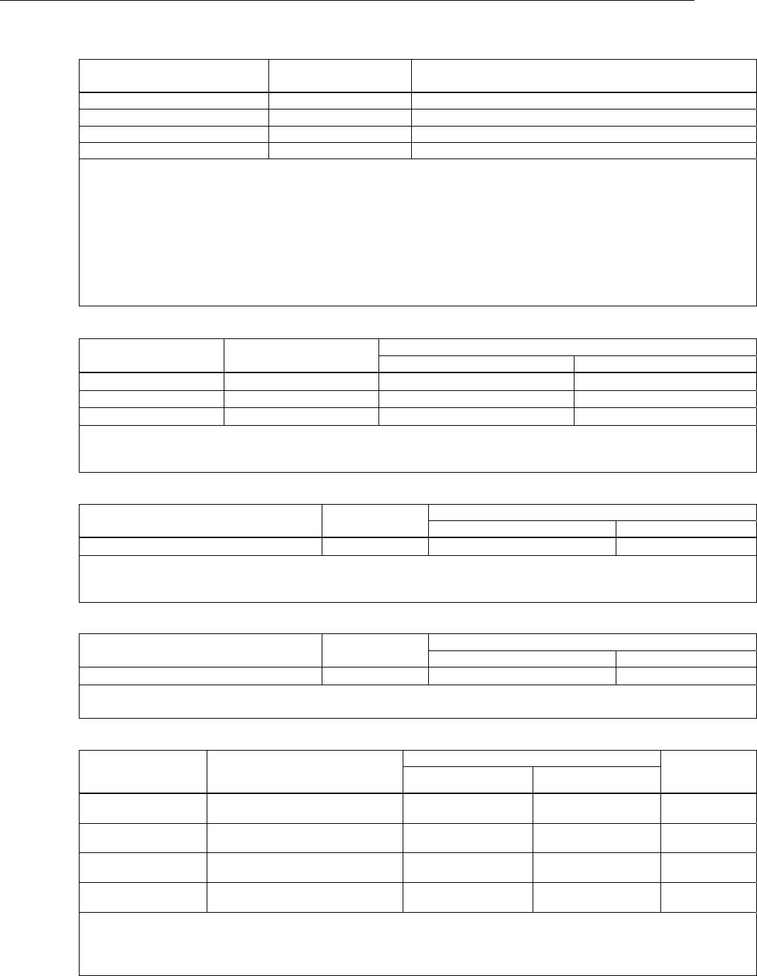
Frequency Measurement
Ranges Resolution 2 Year
1.00 Hz to 110.00 Hz [1] 0.01 Hz 0.05 Hz
110.1 Hz to 1100.0 Hz 0.1 Hz 0.5 Hz
1.101 kHz to 11.000 kHz 0.001 kHz 0.005 kHz
11.01 kHz to 50.00 kHz 0.01 kHz 0.05 kHz
Coupling: AC
Minimum Amplitude for Frequency Measurement (square wave):
<1 kHz: 300 mV p-p
1 kHz to 30 kHz: 1.4 V p-p
>30 kHz: 2.8 V p-p
Maximum input:
<1 kHz: 300 V rms
>1 kHz: 30 V rms
Input Impedance: >4 MΩ
[1] For frequency measurement less than 110.00 Hz, specifications apply for signals with a slew rate >5 volt/millisecond.
±
DC Voltage Output
Range Resolution % of Output + Floor
1-Year 2 Year
±100.000 mV 1 μV 0.01 % + 0.005 mV 0.015 % + 0.005 mV
±1.00000 V 10 μV 0.01 % + 0.00005 V 0.015 % + 0.00005 V
±15.0000 V 100 μV 0.01 % + 0.0005 V 0.015 % + 0.0005 V
Maximum Output Current: 10 mA, In the 100 mV range add 0.010 mV to specification when sourcing >1 mA.
For sourcing dc voltages <110.000 mV, accuracy is not specified in RF fields >1 V/m, 80 MHz to 700 MHz.
Temperature Coefficient: 0.001 % of output + 0.001 % of range / °C (<18 °C or >28 °C)
+DC Current Source
Range/Mode Resolution % of Output + Floor
1-Year 2 Year
0.100 to 22.000 mA 1 μA 0.01 % + 3 μA 0.02 % + 3 μA
Temperature Coefficient: 3 % of specified accuracy / °C (<18 °C or >28 °C)
Source mA Compliance Voltage: 18 V maximum
Source mA Open Circuit Voltage: 30 V maximum
+DC Current Simulate (External Loop Power)
Range/Mode Resolution % of Output + Floor
1-Year 2 Year
0.100 to 22.000 mA (Current Sink) 1 μA 0.02 % + 7 μA 0.04 % + 7 μA
Simulate mA Input Voltage: 15 to 50 V dc, add 300 μA to floor when >25 V is present on the loop
Temperature Coefficient: 3 % of specified accuracy / °C (<18 °C or >28 °C)
Resistance Sourcing
Range Resolution
% of Output + Floor Allowable
Excitation
Current
1-Year 2 Year
10.000 Ω 0.001 Ω 0.01 % + 0.010 Ω 0.015 % + 0.015 Ω 0.1 mA to
10 mA
100.00 Ω [1] 0.01 Ω 0.01 % + 0.02 Ω 0.015 % + 0.03 Ω 0.1 mA to
10 mA
1.0000 kΩ [2] 0.1 Ω 0.02 % + 0.0002 kΩ 0.03 % + 0.0003 kΩ 0.01 mA to
1.0 mA
10.000 kΩ 1 Ω 0.02 % + 0.003 kΩ 0.03 % + 0.005 kΩ 0.01 mA to
1.0 mA
Temperature Coefficient: (0.01 % of output +0.02 % of range / °C (<18 °C or >28 °C).
When connected to mains, accuracy is not specified with conducted RF >1V, 8 to 15 MHz.
[1] Add 0.01 Ω when the excitation current is <1 mA.
[2] Add 0.0015 kΩ when the excitation current is <0.1 mA.
Documenting Process Calibrator
Detailed Specifications
7
Frequency Sourcing
Range Specification
2 Year
Sine Wave: 0.1 Hz to 10.99 Hz 0.01 Hz
Square Wave: 0.01 Hz to 10.99 Hz 0.01 Hz
Sine and Square Wave: 11.00 Hz to 109.99 Hz 0.1 Hz
Sine and Square Wave: 110.0 Hz to 1099.9 Hz 0.1 Hz
Sine and Square Wave: 1.100 kHz to 21.999 kHz 0.002 kHz
Sine and Square Wave: 22.000 kHz to 50.000 kHz 0.005 kHz
Waveform Choices: Zero-symmetric sine wave or positive 50 % duty-cycle square wave
Square Wave Amplitude: 0.1 to 15 V p-p
Square Wave Amplitude Accuracy, 0.01 to 1 kHz: 3 % p-p output + 75 mV, 1 kHz to 50 kHz: 10 % p-p output + 75 mV typical.
Sine Wave Amplitude: 0.1 to 30 V p-p
Sine Wave Amplitude Accuracy, 0.1 to 1 kHz: 3 % p-p output + 75 mV, 1 kHz to 50 kHz: 10 % p-p output + 75 mV typical.
Frequency specifications are valid when averaged ≥100 ms
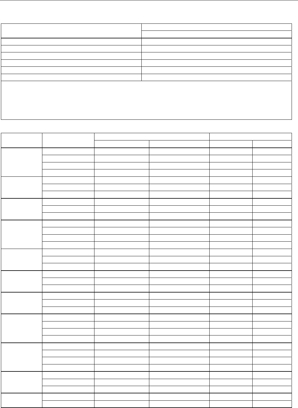
Temperature, Thermocouples
Type Range °C Measure °C Source °C
1-Year 2 Year 1-Year 2 Year
E -250 to -200 1.3 2.0 0.6 0.9
-200 to -100 0.5 0.8 0.3 0.4
-100 to 600 0.3 0.4 0.3 0.4
600 to 1000 0.4 0.6 0.2 0.3
N -200 to -100 1.0 1.5 0.6 0.9
-100 to 900 0.5 0.8 0.5 0.8
900 to 1300 0.6 0.9 0.3 0.4
J -210 to -100 0.6 0.9 0.3 0.4
-100 to 800 0.3 0.4 0.2 0.3
800 to 1200 0.5 0.8 0.3 0.3
K -200 to -100 0.7 1.0 0.4 0.6
-100 to 400 0.3 0.4 0.3 0.4
400 to 1200 0.5 0.8 0.3 0.4
1200 to 1372 0.7 1.0 0.3 0.4
T -250 to -200 1.7 2.5 0.9 1.4
-200 to 0 0.6 0.9 0.4 0.6
0 to 400 0.3 0.4 0.3 0.4
B 600 to 800 1.3 2.0 1.0 1.5
800 to 1000 1.0 1.5 0.8 1.2
1000 to 1820 0.9 1.3 0.8 1.2
R -20 to 0 2.3 2.8 1.2 1.8
0 to 100 1.5 2.2 1.1 1.7
100 to 1767 1.0 1.5 0.9 1.4
S -20 to 0 2.3 2.8 1.2 1.8
0 to 200 1.5 2.1 1.1 1.7
200 to 1400 0.9 1.4 0.9 1.4
1400 to 1767 1.1 1.7 1.0 1.5
C
(W5Re/W26Re)
0 to 800 0.6 0.9 0.6 0.9
800 to 1200 0.8 1.2 0.7 1.0
1200 to 1800 1.1 1.6 0.9 1.4
1800 to 2316 2.0 3.0 1.3 2.0
L -200 to -100 0.6 0.9 0.3 0.4
-100 to 800 0.3 0.4 0.2 0.3
800 to 900 0.5 0.8 0.2 0.3
U -200 to 0 0.6 0.9 0.4 0.6
0 to 600 0.3 0.4 0.3 0.4
753/754
Calibration Manual
8
BP 0 to 1000 1.0 1.5 0.4 0.6
1000 to 2000 1.6 2.4 0.6 0.9
2000 to 2500 2.0 3.0 0.8 1.2
XK -200 to 300 0.2 0.3 0.2 0.5
300 to 800 0.4 0.6 0.3 0.6
Sensor inaccuracies not included.
Accuracy with external cold junction; for internal junction add 0.2 °C
Resolution: 0.1 °C
Temperature Scale: ITS-90 or IPTS-68, selectable (90 is default)
Compensation: ITS-90 per NIST Monograph 175 for B,R,S,E,J,K,N,T; IPTS-68 per IEC 584-1 for B,R,S,E,J,K,T; IPTS-68 per DIN 43710 for L,U.
GOST P 8.585-2001 (Russia) for BP and XK, ASTM E988-96 for C (W5Re/W26Re)
Temperature Coefficient: 0.05 °C/ °C (<18 °C or >28 °C)
0.07 °C/ °C for C type >1800 °C and for BP type >2000 °C
Instrument Operating Temperature: 0 to 50 °C for C and BP type thermocouples / -10 to 50 °C for all other types
Normal Mode Rejection: 40 dB at 50 Hz or 60 Hz nominal
For sourcing thermocouple voltages, accuracy is not specified in RF fields >1 V/m, 80 MHz to 700 MHz.
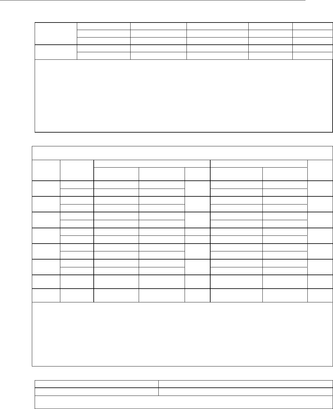
Temperature, Resistance Temperature Detectors
Temperature, RTDs
Degrees or % of Reading [1]
Type (α) Range °C
Measure °C [2] Source °C
A
llowable
Excitation
Current [3]
1-Year 2 Year
Source
Current 1-Year 2 Year
100 Ω
Pt(385)
-200 to 100 0.07 °C 0.14 °C 1 mA 0.05 °C 0.10 °C 0.1 to
10 mA
100 to 800 0.02 % + 0.05 °C 0.04 % + 0.10 °C 0.0125 % + 0.04 °C 0.025 % + 0.08 °C
200 Ω
Pt(385)
-200 to 100 0.07 °C 0.14 °C 500 μA 0.10 °C 0.20 °C 0.1 to
1 mA
100 to 630 0.02 % + 0.05 °C 0.04 % + 0.10 °C 0.017 % + 0.09 °C 0.034 % + 0.18 °C
500 Ω
Pt(385)
-200 to 100 0.07 °C 0.14 °C 250 μA 0.08 °C 0.16 °C 0.1 to
1 mA
100 to 630 0.02 % + 0.05 °C 0.04 % + 0.10 °C 0.017 % + 0.06 °C 0.034 % + 0.12 °C
1000 Ω
Pt(385)
-200 to 100 0.07 °C 0.14 °C 150 μA 0.06 °C 0.12 °C 0.1 to
1 mA
100 to 630 0.02 % + 0.05 °C 0.04 % + 0.10 °C 0.017 % + 0.05 °C 0.034 % + 0.10 °C
100 Ω
Pt(3916)
-200 to 100 0.07 °C 0.14 °C 1 mA 0.05 °C 0.10 °C 0.1 to
10 mA
100 to 630 0.02 % + 0.05 °C 0.04 % + 0.10 °C 0.0125 % + 0.04 °C 0.025 % + 0.08 °C
100 Ω
Pt(3926)
-200 to 100 0.08 °C 0.16 °C 1 mA 0.05 °C 0.10 °C 0.1 to
10 mA
100 to 630 0.02 % + 0.06 °C 0.04 % + 0.12 °C 0.0125 % + 0.04 °C 0.025 % + 0.08 °C
10 Ω
Cu(427) -100 to 260 0.2 °C 0.4 °C 3 mA 0.2 °C 0.4 °C 1 to
10 mA
120 Ω
Ni(672) -80 to 260 0.1 °C 0.2 °C 1 mA 0.04 °C 0.08 °C 0.1 to
10 mA
[1] Specifications are valid to k=3
Sensor inaccuracies not included
[2] For two and three-wire RTD measurements, add 0.4 °C to the specifications.
Resolution: 0.01 °C except 0.1 °C for 10 Ω Cu(427)
Temperature Coefficient: 0.01 °C/°C for measure, 0.02 °C/°C (<18 °C or >28 °C) for source
[3] Supports pulsed transmitters and PLCs with pulse times as short as 1 ms
RTD Reference:
Pt(385): IEC 60751, 2008
Pt(3916): JIS C 1604, 1981
Pt(3926), Cu(427), Ni(672): Minco Application Aid #18
Loop Power
Open Circuit Loaded Circuit
26 V ±10 % 18 V minimum at 22 mA
Short circuit protected to 25 mA
Output Resistance: 250 Ω nominal

Documenting Process Calibrator
Performance Verification Tests
9
Performance Verification Tests
Fluke recommends re-certification each year. To re-certify, do the verification procedure.
If test points are out of tolerance, calibrate the Product and then re-verify. Two-year
specifications are included if the highest accuracy is not necessary.
Use the subsequent tests to make sure that the Product is inside its specification limits.
Verification Equipment
The equipment necessary for verification of the Product is shown in Table 2. If these
instruments are not available, you can replace them with other source and measure
instruments that have the same the minimum specification requirements.
Table 2. Equipment Required for Verification
Equipment Minimum Specification Recommended Model
Calibrator
0.002 % for DC Voltage,
Resistance and Current. 0.01 % for
AC Volt
Fluke 5522A
Frequency Counter 1 Hz to 50 kHz, 25 ppm timebase Tektronix FCA3000
Oscilloscope 1 Hz to 50 kHz (duty cycle accuracy
1 %) Fluke 123
DMM 0.002 % for DC Voltage,
Resistance and Current Fluke 8508A
2-Short jumpers banana type Fluke PN 944632
2-Test leads banana to banana type Fluke TL20
Thermocouple miniplug polarize, with type-K thermocouple
welded to copper wire see Figure 10
Lag bath
characterized by a 0.1 °C standard
thermometer (0.02 °C resolution)
and a 1-pint thermos bottle
Fluke 1551A Stik Thermometer, Dewar
Flask and Cap
Smart (HART) Pressure Transmitter HART communication protocol Rosemount 1151 or 3051
HART Interface Cable Assembly Fluke PN 3562160

753/754
Calibration Manual
10
How to Verify
For each procedure there is a table of test points and permitted readings. If the result of
the test is not in the range shown, the Unit Under Test (UUT) is out of tolerance and must
be re-calibrated or repaired if necessary. There are columns for 1 and 2-year
specifications wherever the specifications are different.
Follow these general instructions for all the tests:
• For all tests, operate the UUT on battery power. Make sure the battery is fully
charged.
• For measurement functions, push the Range softkey to lock the range on the
range specified in the test points table. It can be necessary to push the Range
softkey more than once.
• Ranges in the specification tables include the 10 % over-range capability. Range
names on the Product display do not include the 10 % over-range. For example,
the UUT display shows Range 100 mV, but the range is specified to 110 mV.
• Let each piece of verification equipment have its specified warm-up time.
• A minimum of 5 minutes is necessary for warm up. The source circuits shut off
when not in operation. A separate warm up is necessary when Source mode is
first used.
• For each test, make sure the verification equipment is stable and that the
“unsettled” annunciator on the UUT is not shown.
DC Volts Measurement
To verify the dc volts measurement function:
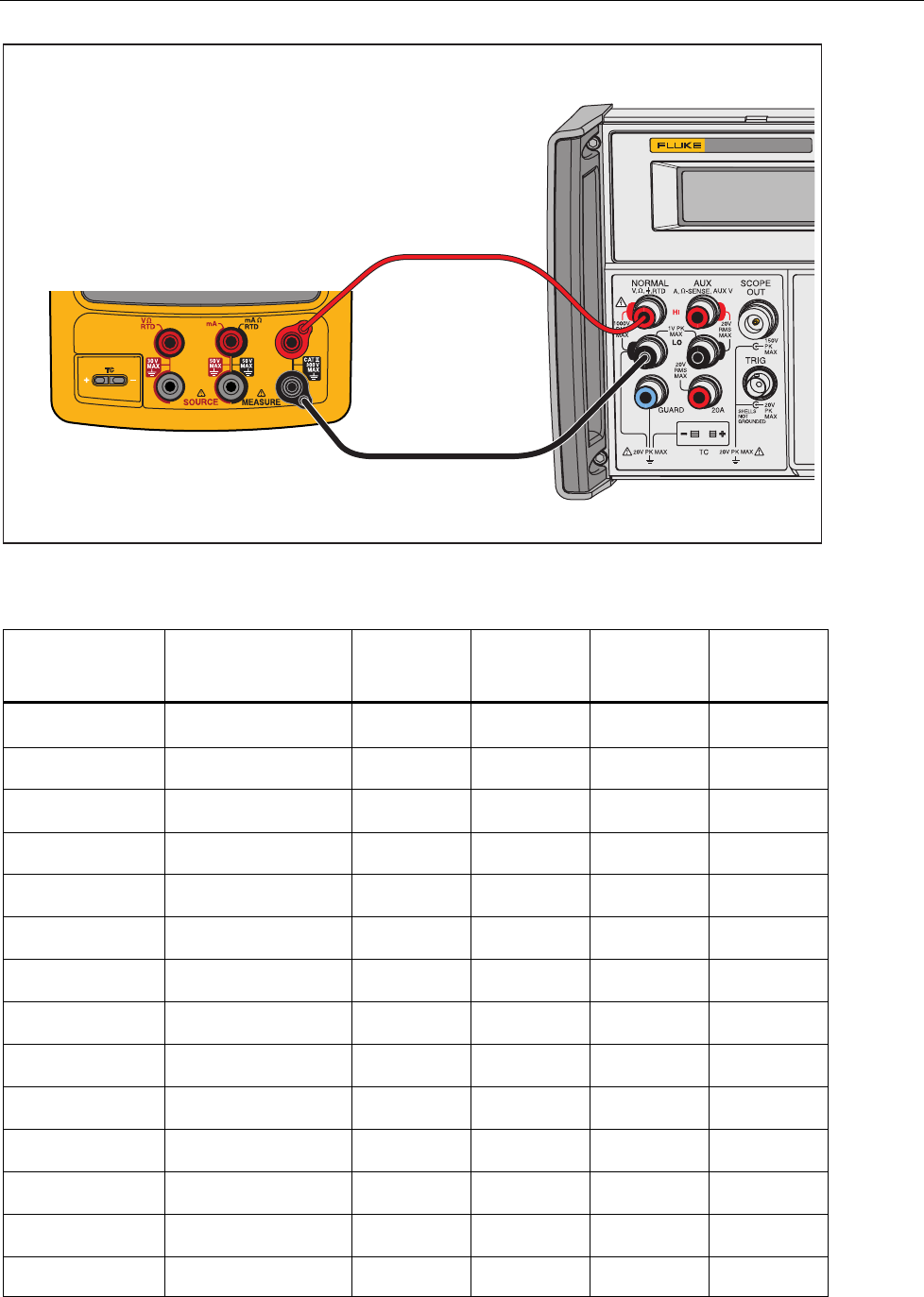
1. Connect the UUT to the 5522A as shown in Figure 1.
WCaution
To prevent possible damage to the Product, do not force a dual
banana plug between any two jacks in the horizontal
orientation. Doing so will damage the jacks. Use the supplied
jumper wire when needed for RTD measurements. A dual
banana plug may be used in the vertical orientation.
2. Set the UUT to the dc volts measurement function.
3. Push the Range softkey on the UUT to lock on the 100 mV range.
4. Set the 5522A to the first test point in Table 3.
5. See if the value shown on the UUT is in the range shown in the applicable
column.
6. Continue through the test points. Make sure to lock the UUT on the specified
range.
7. When you complete the test, set the 5522A to STANDBY.
Documenting Process Calibrator
Performance Verification Tests
11
5522A CALIBRATOR
Fluke 75X
Fluke 5522A
gso03.eps
Figure 1. DC Volts and AC Volts Measurement Connections
Table 3. DC Volts Measurement Verification Points
UUT Range Input V dc Minimum
1-Year
Maximum
1-Year
Minimum
2-Year
Maximum
2-Year
100.000 mV 0 -0.005 0.005 -0.005 0.005
100.000 mV 0.1 99.975 100.025 99.965 100.035
100.000 mV -0.1 -100.025 -99.975 -100.035 -99.965
3.00000 V 0 -0.00005 0.00005 -0.00005 0.00005
3.00000 V 1.0 0.99975 1.00025 0.99965 1.00035
3.00000 V 2.0 1.99955 2.00045 1.99935 2.00065
3.00000 V 3 2.99935 3.00065 2.99905 3.00095
3.00000 V -3 -3.00065 -2.99935 -3.00095 -2.99905
30.0000 V 0 -0.0005 0.0005 -0.0005 0.0005
30.0000 V 30 29.9935 29.9870 29.9905 30.0095
30.0000 V -30 -30.0065 -29.9935 -30.0095 -29.9905
300.00 V 0 -0.05 0.05 -0.05 0.05
300.00 V 295 294.80 295.20 294.74 295.26
300.00 V -295 -295.20 -294.80 -295.26 -294.74

753/754
Calibration Manual
12
AC Volts Measurement
To verify the ac volts measurement function:
1. Connect the UUT to the 5522A as shown in Figure 1.
2. Set the UUT to the ac volts measurement function.
3. Push the Range softkey on the UUT to lock on the 3.0 V range.
4. Set the 5522A to the first test point in Table 4.
5. Stop to let the output become stable.
6. See if the value shown on the UUT is in the range shown in the applicable
column.
7. Continue through the test points. Make sure to lock the UUT on the specified
range.
8. When you complete the test, set the 5522A to STANDBY.
Table 4. AC Volts Measurement Verification Points
UUT
Ran
g
e
Input
(
RMS
)
Frequency Minimum
1-Yea
r
Maximum
1-Yea
r
Minimum
2-Yea
r
Maximum
2-Yea
r
3.000 V 0.26 500 Hz 0.257 0.263 0.253 0.267
3.000 V 3 500 Hz 2.983 3.017 2.966 3.034
3.000 V 0.26 40 Hz 0.257 0.263 0.253 0.267
3.000 V 3 40 Hz 2.983 3.017 2.966 3.034
30.00 V 2.6 500 Hz 2.567 2.633 2.53 2.67
30.00 V 30 500 Hz 29.830 30.170 29.66 30.34
30.00 V 2.6 40 Hz 2.567 2.633 2.53 2.67
30.00 V 30 40 Hz 29.830 30.170 29.66 30.34
300.0 V 27 500 Hz 26.665 27.335 26.5 27.5
300.0 V 295 500 Hz 293.325 296.675 291.9 298.2
300.0 V 27 40 Hz 26.665 27.335 26.5 27.5
300.0 V 295 50 Hz 293.325 296.675 291.9 298.2
Documenting Process Calibrator
Performance Verification Tests
13
DC Current Measurement
To verify the dc current measurement function:
1. Connect the UUT to the 5522A and the 8508A as shown in Figure 2.
2. Disconnect the jumpers on the three common jacks (lows) of the UUT if they are
present.
3. Set the UUT and the 8508A to the dc current measurement function and the
5522A to source dc current.
4. Push the Range softkey on the UUT to lock on the 30 mA range.
5. Set the 5522A to the first test point in Table 5, and edit its output so that the
correct value shows on the 8508A.
6. See if the value shown on the UUT is in the range shown in the applicable
column.
7. Continue through the test points. Make sure to lock the UUT on the specified
range.
8. When you complete the test, set the 5522A to STANDBY.
5522A
CALIBRATOR
Fluke 75X
Fluke 8508A
Fluke 5522A
gso04.eps
Figure 2. DC Current Measurement Verification Connections

753/754
Calibration Manual
14
Table 5. DC Current Measurement Verification Points
UUT Range Input mA Minimum
1-Yea
r
Maximum
1-Yea
r
Minimum
2-Yea
r
Maximum
2-Yea
r
30 mA 4 mA 3.995 4.005 3.992 4.008
30 mA 20 mA 19.993 20.007 19.990 20.010
30 mA 30 mA 29.992 30.008 29.989 30.012
30 mA -30 mA -30.008 -29.992 -30.012 -29.989
100 mA 0 mA -0.02 0.02 -0.03 0.03
100 mA 100 mA 99.97 100.03 99.96 100.04
100 mA -100 mA -100.03 -99.97 -100.04 -99.96
Resistance Measurement
To verify the resistance measurement function:
1. Connect the UUT to the 5522A as shown in Figure 3.
2. Use a four-wire connection at the 5522A, transitioning to two wires at the UUT,
and turn on Two-Wire Compensation.
3. Set the UUT to the resistance measurement function.
4. Push the Range softkey on the UUT to lock on the 10 Ω range.
5. Set the 5522A to the first test point in Table 6.
6. See if the value shown on the UUT is in the range shown in the applicable
column.
7. Continue through the test points. Make sure to lock the UUT on the specified
range.
8. When you complete the test, set the 5522A to STANDBY.

Documenting Process Calibrator
Performance Verification Tests
15
5522A CALIBRATOR
Fluke 75X
Fluke 5522A
2-WIRE COMP ON
gso05.eps
Figure 3. Resistance Measurement Verification Connections
Table 6. Resistance Measurement Verification Points
UUT
Range Input Minimum
1-Year
Maximum
1-Year
Minimum
2-Year
Maximum
2-Year
10.000 Ω 0 Ω -0.050 0.050 -0.070 0.070
10.000 Ω 10 Ω 9.945 10.055 9.923 10.077
100.00 Ω 0 Ω -0.05 0.05 -0.07 0.07
100.00 Ω 100 Ω 99.90 100.10 99.86 100.14
1000.0 Ω 0 Ω -0.5 0.5 -0.7 0.7
1000.0 Ω 1 kΩ 999.0 1001.0 998.6 1001.4
10.000 kΩ 0 Ω -0.010 0.010 -0.015 0.015
10.000 kΩ 10 kΩ 9.980 10.020 9.970 10.030
753/754
Calibration Manual
16
Frequency Measurement
To verify the frequency measurement function:
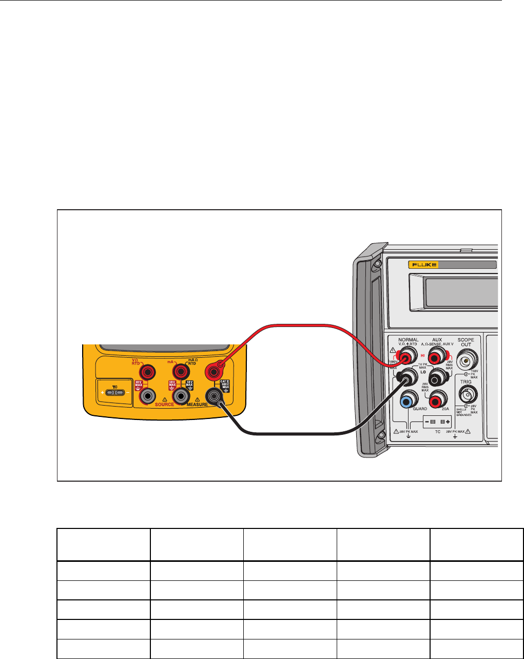
1. Connect the UUT as shown in Figure 4 .
2. Set the UUT to the frequency measurement function.
3. Select the <20 Hz range for the first step. Use the ≥20 Hz range thereafter.
4. Set the 5522A to the first test point in Table 7.
5. See if the frequency value shown on the UUT is in the range shown in the
applicable column.
6. Continue through the test points.
7. When you complete the test, set the 5522A to STANDBY.
5522A CALIBRATOR
Fluke 75X
Fluke 5522A
gso06.eps
Figure 4. Frequency Measurement Verification Connections
Table 7. Frequency Measurement Verification Points
UUT Range Frequency Input V RMS Minimum
1- & 2-Year
Maximum
1- & 2-Year
<20 Hz 10 Hz 300 mV 9.95 10.05
>20 Hz 150 Hz 300 mV 149.5 150.5
>20 Hz 1.2 kHz 1.0 V 1.195 1.205
>20 Hz 12 kHz 1.0 V 11.95 12.05
>20 Hz 49 kHz 2.0 V 48.95 49.05
Documenting Process Calibrator
Performance Verification Tests
17
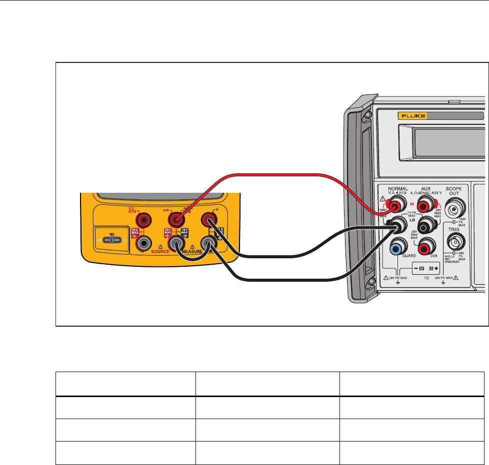
DC Volts Source
To verify the dc volts source function:
1. Connect the UUT to the 8508A as shown in Figure 5.
2. Set the 8508A to measure dc volts.
3. Set the UUT to the dc volts source function at -10 mV. Let the UUT warm up for
a minimum of 5 minutes before you read the first indication.
4. See if the value shown on the 8508A is in the range shown in the applicable
column in Table 8.
5. Continue through the test points. See if the value shown on the UUT is in the
range shown in the applicable column.
6. When you complete the test, push on the UUT two times to turn the source
function off. This conserves battery life.
Fluke 75X
Fluke 8508A
gso07.eps
Figure 5. DC Volts Source Verification Connections
Table 8. DC Volts Source Verification Points
UUT
Range UUT Output Minimum
1-Year
Maximum
1-Year
Minimum
2-Year
Maximum
2-Year
100.000 10 mV 9.9940 10.0060 9.9935 10.0065
100.000 0.1 V 99.9850 100.0150 99.9800 100.0200
1.00000 V 0.15 V 0.14994 0.15007 0.14993 0.15007
1.00000 V 1 V 0.99985 1.00015 0.99980 1.00020
15.0000 V 1.5 V 1.49935 1.50065 1.49928 1.50073
15.0000 V 10 V 9.99850 10.00150 9.99800 10.00200
753/754
Calibration Manual
18
DC Current Source
To verify the dc current source function.
1. Connect the UUT to the 8508A as shown in Figure 6.
2. Set the 8508A to DC Current.
3. Set the UUT to dc current source (not simulate transmitter) function at 2 mA.
4. See if the value shown on the 8508A is in the range shown in the applicable
column in Table 9.
5. Continue through the test points. See if the value shown on the UUT is in the
range shown in the applicable column.
6. When you complete the test, push on the UUT two times to turn off the
source function. This conserves battery life.
Fluke 75X
Fluke 8508A
gso08.eps
Figure 6. DC Current Source Verification Connections
Table 9. DC Current Source Verification Points
UUT
Range UUT Output Minimum
1-Year
Maximum
1-Year
Minimum
2-Year
Maximum
2-Year
22.000 mA 2 mA 1.99680 2.00320 1.99660 2.00340
22.000 mA 4 mA 3.99660 4.00340 3.99620 4.00380
22.000 mA 12 mA 11.99580 12.00420 11.99460 12.00540
22.000 mA 21 mA 20.99490 21.00510 20.99280 21.00720
Documenting Process Calibrator
Performance Verification Tests
19
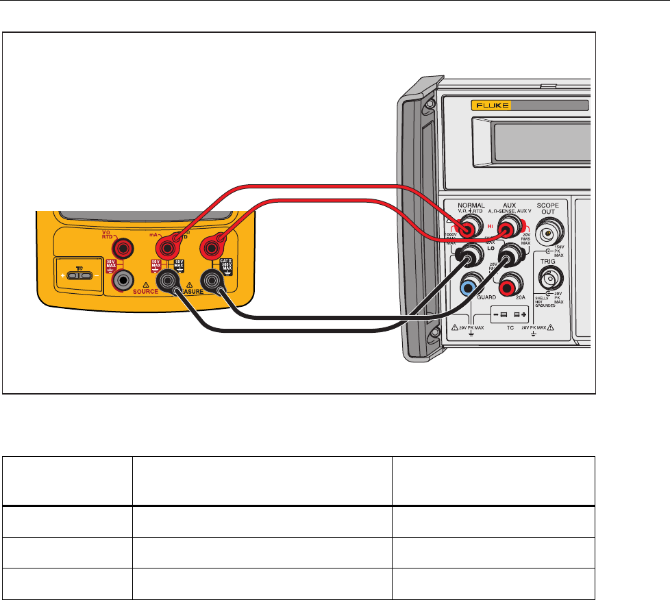
Simulate Transmitter Function
To verify the simulate transmitter function (accessed through dc current source function):
1. Connect the UUT, 8508A, and 5522A as shown in Figure 7. The 5522A is used
as a stable dc voltage source. Its value is not critical, and a different dc source
such as a battery can be used if necessary.
2. Set the 8508A to DC Current .
3. Set the UUT to the [mA Source] function and then select Simulate Transmitter.
4. Set the UUT source value to 4 mA.
5. Set the 5522A to output 8 V dc.
6. See if the value shown on the 8508A is in the range shown in Table 10.
7. Change the UUT source value to 22 mA and examine the results again in Table 10.
8. When you complete the test, set the 5522A to STANDBY and push on the
UUT two times to turn the source function off. This conserves battery life.
5522A CALIBRATOR
Fluke 75X
Fluke 8508A
Fluke 5522A
gso09.eps
Figure 7. Simulate Transmitter Verification Connections
753/754
Calibration Manual
20
Table 10. Simulate Transmitter Verification Points
UUT Range UUT Output Minimum
1-Year
Maximum
1-Year
Minimum
2-Year
Maximum
2-Year
22.000 mA 4 3.99220 4.00780 3.99140 4.00860
22.000 mA 21 20.98880 21.01120 20.98460 21.01540
Resistance Source Function
To verify the resistance source function:
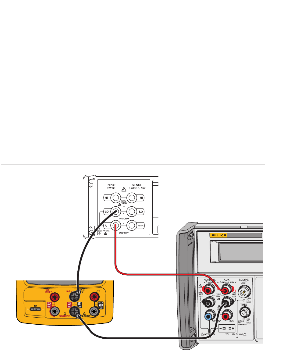
1. Connect the UUT to the 8508A as shown in Figure 8. Use a four-wire connection
transitioning to two wires at the UUT.
2. Set the UUT to the resistance source function at 0.1 Ω.
3. On the 8508A, select four-wire ohms measurement and up-range to the 200 Ω
range. Use the 200 Ω range for the first five tests points, and autorange
thereafter. The low range of the 8508A supplies too much current into the UUT.
4. See if the value shown on the 8508A is in the range shown in Table 11.
5. Continue through the test points. See if the value shown on the UUT is in the
range shown in the applicable column of Table 11.
6. When you complete the test, push on the UUT two times to turn off the
source function. This conserves battery life.
Fluke 75X
Fluke 8508A
gso10.eps
Figure 8. Resistance Source Verification Connections
Documenting Process Calibrator
Performance Verification Tests
21
Table 11. Resistance Source Verification Points
UUT Range UUT Output Minimum
1-Yea
r
Maximum
1-Yea
r
Minimum
2-Yea
r
Maximum
2-Yea
r
10.000 Ω 0.1 Ω 0.0900 0.1100 0.0850 0.1150
10.000 Ω 1 Ω0.9899 1.0101 0.9849 1.0152
10.000 Ω 10 Ω 9.9890 10.0110 9.9835 10.0165
100.00 Ω 20 Ω 19.978 20.022 19.967 20.033
100.00 Ω 100 Ω 99.970 100.030 99.955 100.045
1000.0 Ω 200 Ω 199.76 200.24 199.64 200.36
1000.0 Ω 1000 Ω 999.60 1000.40 999.40 1000.60
10.000 kΩ 2 kΩ 1.9966 2.0034 1.9944 2.0056
10.000 kΩ 10 kΩ 9.9950 10.0050 9.9920 10.0080
Frequency Source
To verify the frequency source function:
1. Connect the UUT to the Tektronix FCA3000 Counter as shown in Figure 9.
2. Set the UUT to source, frequency, 1.000 Vpp, square wave, at 5 Hz.
3. See if the value shown on the Tektronix FCA3000 is in the range shown in the
applicable column in Table 11
4. Use the Fluke 123 to examine the wave forms. For the square wave, a positive
square wave, with a 50 % duty-cycle (±5 %), and 1.0 V peak amplitude. See that
the amplitude is correct for the applied signal. For the sine wave, make sure you
have the correct frequency, waveform, and amplitude.
5. Continue through the test points. See if the value shown on the UUT is in the
range shown in the applicable column of Table 12.
6. When you complete the test, push on the UUT two times to turn off the
source function. This conserves battery life.
753/754
Calibration Manual
22
TEKTRONIX FCA3000 Counter
Fluke 75x
Fluke 123
Use Channel A
BNC Input
gso11.eps
Figure 9. Frequency Source Verification Connections
Table 12. Frequency Source Verification Points
UUT Range Frequency @ 1 Vpp Minimum
Fre
q
uenc
y
Maximum
Fre
q
uenc
y
10.99 Hz 5 Hz Sine 4.99 Hz 5.01 Hz
1099.9 Hz 1 kHz Sine 999.9 Hz 1000.1 Hz
21.999 kHz 10 kHz Sine 9.998 kHz 10.002 kHz
50 kHz 49 kHz Sine 48.995 kHz 49.005 kHz
10.99 Hz 5 Hz Square 4.99 Hz 5.01 Hz
1099.9 Hz 1 kHz Square 999.9 Hz 1000.1 Hz
UUT Range Frequency @ 7.5 Vpp Minimum Frequency Maximum Frequency
109.99 Hz 50 Hz Square 49.9 Hz 50.1 Hz

Documenting Process Calibrator
Performance Verification Tests
23
Thermocouple Measure
To verify the thermocouple measure function.
1. Use Type-K thermocouple wire and copper wire to connect the 5522A output to
the UUT-TC jack as shown in Figure 10. The Type K-to-Copper junctions must
be welded or made with tight screw terminals and submersed in the lag bath
(room temperature). Use the standard thermometer (0.1 °C accuracy) to measure
the temperature of the lag bath.
2. Set the 5522A to source dc millivolts and the UUT to the thermocouple measure
function, TC Type K; ITS-90 scale, internal reference, and °C.
3. Stop for a minimum of 1 minute for thermal “emfs” (caused by insertion of the
connectors) to dissipate, and let the lag bath become stable for a minimum of
15 minutes.
4. Use the 5522A to source the millivolt equivalents of the temperatures in
Table 13. At each point, correct the 5522A output voltage. To do this, subtract
the millivolt equivalent of the temperature at the lag bath junction (use reference
chart below).
5. Continue through the test points. See if the value shown on the UUT is in the
range shown in the applicable column of Table 13.
6. When you complete the test, set the 5522A to STANDBY.
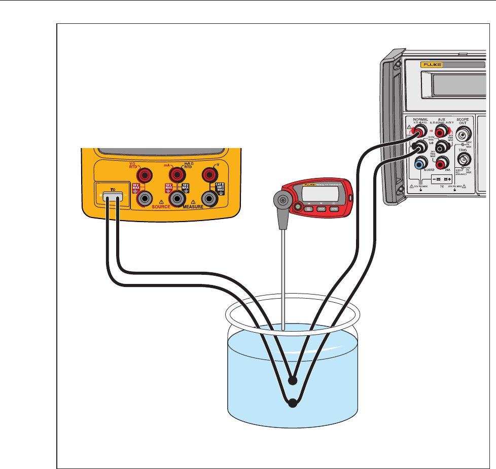
753/754
Calibration Manual
24
5522A
CALIBRATOR
Fluke 75X
Room Temperature
Lab Bath
Fluke 1551A Ex
Thermometer
Fluke 5522A
TYPE-K
Thermocouple
Wire
CuCu
gso12.eps
Figure 10. Temperature Measure (TC) Verification Connections

Documenting Process Calibrator
Performance Verification Tests
25
Table 13. Temperature Measure Verification
Input dcmV (referenced to 0 °C) Minimum
1-Year °C
Maximum
1-Year °C
Minimum
2-Year °C
Maximum
2-Year °C
-5.550 mV (-180 °C) -180.9 -179.1 -181.2 -178.8
0.000 mV (0 °C) -0.5 0.5 -0.6 0.6
52.410 mV (1300 °C) 1299.1 1300.9 1298.8 1301.2
Lag Bath Reference Table, Type K, ITS-90
Tem
p
. °C 18 19 20 21 22 23 24 25 26 27 28
mV 0.718 0.758 0.798 0.838 0.879 0.919 0.960 1.000 1.041 1.081 1.122
Thermocouple Source
To verify the thermocouple source function:
Note
This test uses a Type-K thermocouple setting on the UUT.
1. Use Type-K thermocouple wire and copper wire to connect the 8508A to the
UUT -TC jack as shown in Figure 10 (the 8508A is used in place of the 5522A).
The type K-to-copper junctions must be welded or made with tight screw
terminals and submersed in the lag bath (room temperature). Use the standard
thermometer (0.1 % accuracy) to measure the temperature of the lag bath.
2. Set the UUT to the thermocouple source function, linear mode, TC type K, ITS-
90 scale, internal reference, and °C.
3. Set the 8508A to measure mV dc.
4. Stop for a minimum of 1 minute for thermal “emfs” (caused by insertion of the
connectors) to dissipate, and let the lag bath become stable for a minimum of 15
minutes.
5. Source each of the temperatures in Table 14 from the UUT. At each point,
correct the DMM measured voltage. To do this, add the millivolt equivalent of
the Type-K junction at the lag bath temperature (use the Type-K ITS-90 chart).
6. Continue through the test points. See if the value shown on the UUT is in the
range shown in the applicable column in Table 14.
7. When you complete the test, push on the UUT two times to turn the source
function off. This conserves battery life.

753/754
Calibration Manual
26
Table 14. Temperature Source Verification (Type-K Thermocouple, ITS-90)
UUT
Output Nominal DC mV Minimum
1-Year
Maximum
1-Year
Minimum
2-Year
Maximum
2-Year
-180 °C -5.5504 -5.5616 -5.539 -5.5653 -5.5353
0 °C 0.0000 -0.0197 0.0197 -0.0237 0.0237
1300 °C 52.4103 52.3928 52.4277 52.3893 52.4312
RTD Measure, Four-Wire
Note
It is necessary to use a separate verification procedure for the three-wire
RTD measure function because it uses different circuits. The two-wire RTD
measure circuit is tested during the Ohms Measure procedure. If a 5522A is
not available, replace it with a variable resistance source such as a general
resistance RTD-100 RTD simulator and a DMM to measure the variable
resistance source for accuracy. Use the resistance equivalents shown in
Table 15.
To verify the four-wire RTD Measure function:
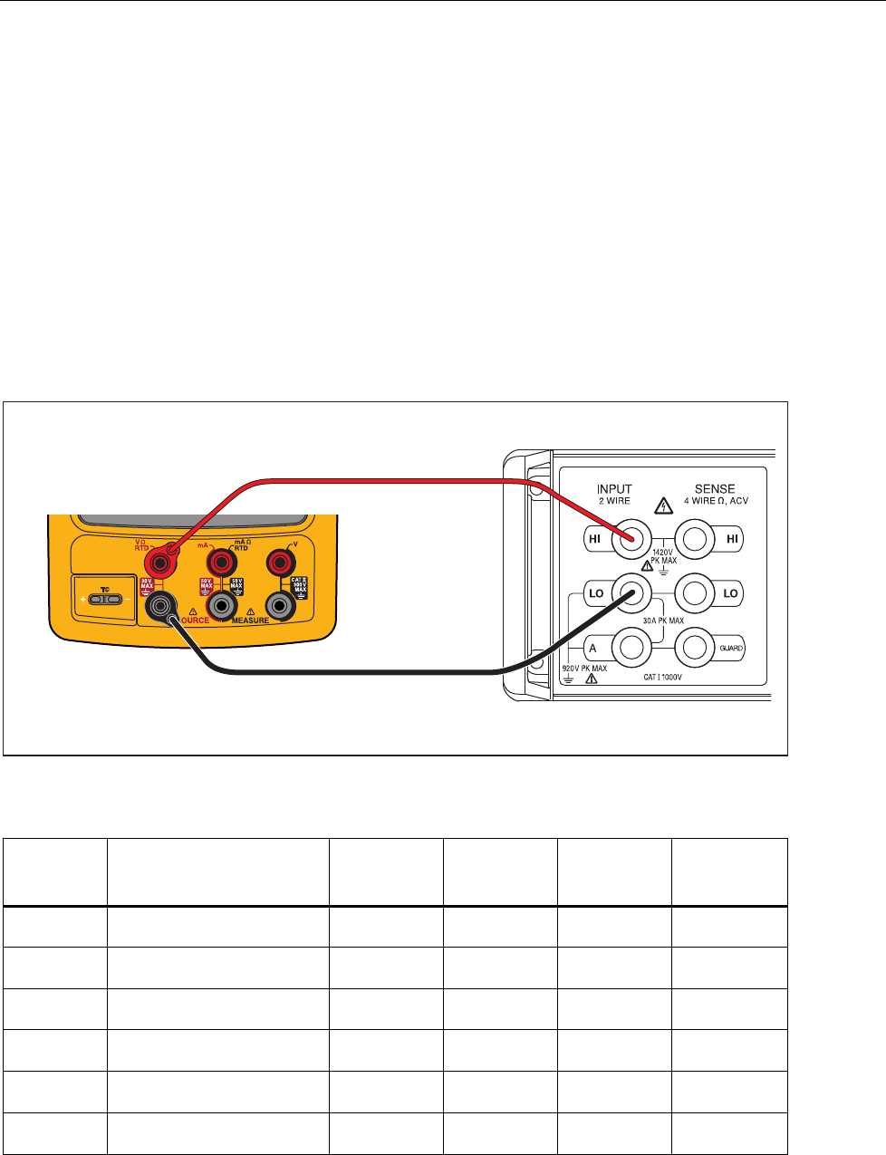
1. Connect the UUT to the 5522A as shown in Figure 11. Use a four-wire
connection and four-wire compensation.
2. Set the UUT to the RTD measure function, Pt100 (385), ITS-90 scale, and four-
wire termination.
3. Set the 5522A to RTD, Pt100 (385) at -180 °C, ITS-90 scale, and comp four-
wire.
4. Set the 5522A to [Operate].
5. See if the value shown on the UUT is in the range shown in the applicable
column in Table 15.
6. Continue through the test points.
7. When you complete the test, set the 5522A to STANDBY.
Documenting Process Calibrator
Performance Verification Tests
27
5522A CALIBRATOR
Fluke 75X
Fluke 5522A
4-WIRE COMP ON
4-WIRE RTD
gso13.eps
Figure 11. Four-Wire RTD Measure Verification Connections
Table 15. RTD Measure Verification (100W Pt (385), Four-Wire Connection)
Input °C
(Resistance) 1-Year ( °C ) 2-Year ( °C )
-180 °
(
27.096 Ω
)
-179.93 to -180.07 -179.86 to -180.14
100 °
(
138.505 Ω
)
99.93 to 100.07 99.86 to 100.14
780 ° (369.712 Ω) 779.79 to 780.21 779.59 to 780.41
RTD Measure, Three-Wire
Note
If a 5522A is not available, substitute a variable resistance source such as a
General Resistance RTD-100 RTD Simulator and a DMM to measure the
variable resistance source accurately. Use the resistance equivalents shown
in Table 16.
To verify the three-wire RTD measure function:
1. Connect the UUT to the 5522A as shown in Figure 12.
2. Set the UUT to the RTD measure function, Pt100 (385), ITS-90 scale, three-wire
termination.
3. Set the 5522A to RTD, Pt100 (385) at -180 °C, ITS-90 scale, and comp four-wire
to “OFF” position.
4. Set the 5522A to [Operate].
5. See if the value shown on the UUT is in the range shown in the applicable
column in Table 16.
753/754
Calibration Manual
28
6. Continue through the test points.
7. When you complete the test, set the 5522A to STANDBY.
5522A CALIBRATOR
Fluke 75X
Fluke 5522A
gso14.eps
Figure 12. Three-Wire RTD Measure Verification Connections
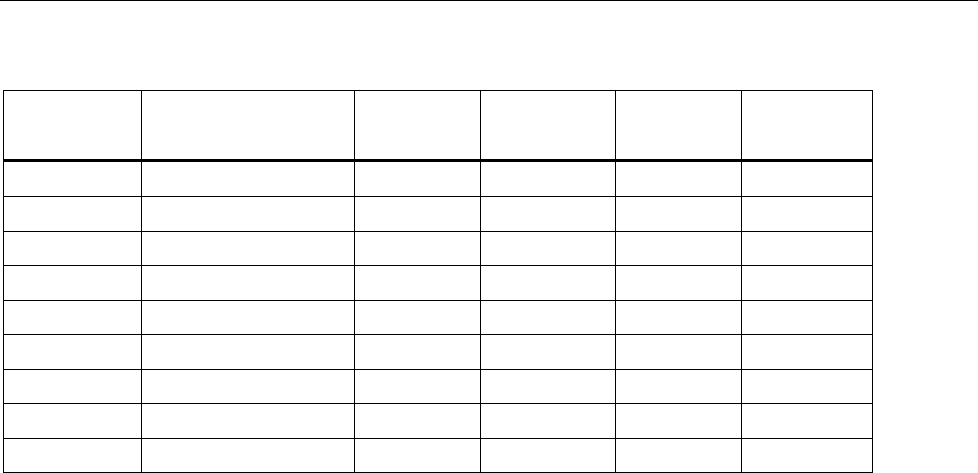
Table 16. RTD Measure Verification (100W Pt (385), Three-Wire Connection)
Input °C (Resistance) 1-Year ( °C ) 2-Year ( °C )
-180 °
(
27.096 Ω
)
-179.53 to -180.47 -179.46 to -180.54
100 °
(
138.505 Ω
)
99.53 to 100.47 99.46 to 100.54
780 ° (369.712 Ω) 779.39 to 780.61 779.19 to 780.81

Documenting Process Calibrator
Performance Verification Tests
29
RTD Source
To verify the RTD Source function:
1. Connect the UUT to the 8508A DMM as shown in Figure 8. Use a four-wire
connection transitioning to two-wires at the UUT.
2. Set the 8508A to 4-Wire Ohms, auto-range.
3. Set the UUT to the RTD source function, Pt100 (385) at -180 °C, ITS-90 scale.
4. See if the value shown on the DMM is in the range shown in the applicable
column in Table 17.
5. Continue through the test points.
6. When you complete the test, push on the UUT two times to turn the source
function off. This conserves battery life.
Table 17. RTD Source Verification (100W Pt (385))
UUT
Output Nominal (Ohms) Minimum
1-Year
Maximum
1-Year
Minimum
2-Year
Maximum
2-Year
-180 °C 27.096 27.075 27.118 27.054 27.139
100 °C 138.505 138.487 138.524 138.468 138.543
780 °C 369.712 369.6707 369.7532 369.630 369.795
753/754
Calibration Manual
30
Loop Power
To verify the loop power function.
1. Connect the UUT to the 8508A DMM as shown in Figure 13.
2. On the UUT push s, , select Loop Power, and push again.
3. Observe the no-load voltage reading on the DMM and verify that it is within the
range 23.4 V to 28.6 V.
4. When complete, disable Loop Power through the setup menu or turn the UUT
off. This conserves battery life.
Fluke 75X
Fluke 8508A
gso15.eps
Figure 13. Loop Power Verification Connections
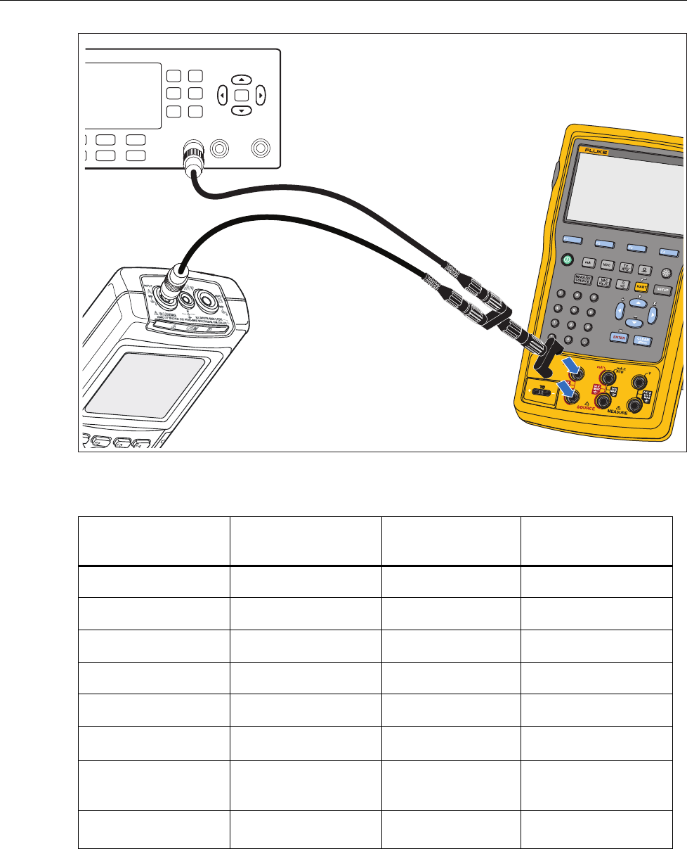
HART Mode Verification (754 Only)
The subsequent test makes sure that the 754 can communicate over a serial HART®
(Highway Addressable Remote Transducer) interface to a HART transmitter. The
calibrator communicates with virtually all HART transmitters and related software
versions. These are “supported transmitters”. All other transmitters are “generic”. A
Smart (HART) Pressure Transmitter is necessary for this procedure. The Rosemount
Models 1151 or 3051 are recommended (may be substituted with any HART
communicator protocol device).
This verification test is a pass or fail test. No calibration is necessary for the HART
mode. If the Product fails this test, repair is necessary. Refer to the 754 HART Mode
Users Guide for more data on the HART feature.
Documenting Process Calibrator
HART Mode Verification (754 Only)
31
It is not necessary to open the case or adjust the Product to do this test. Make the
necessary connections and verify that the Product responds as necessary.
1. Push s. The first setup screen shows.
2. Push or to select HART Channel.
3. Push .
4. Push or to select mA Jack.
5. Push .
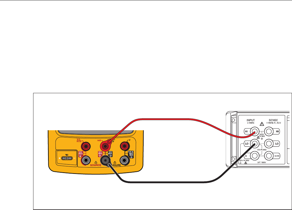
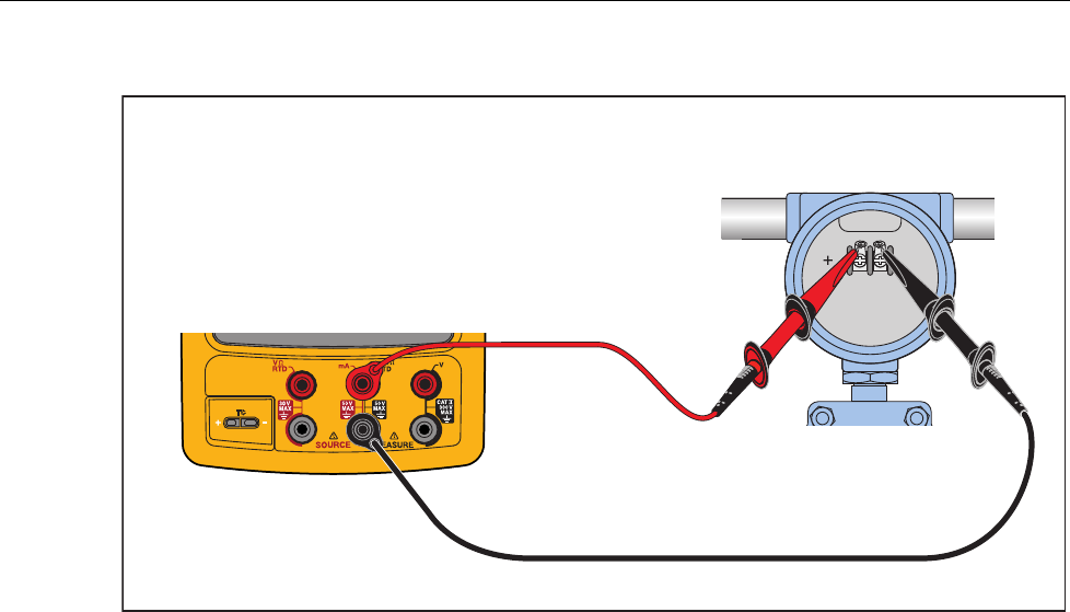
6. Connect the Product to the HART transmitter as shown in Figure 15.
7. Push r to start HART mode. If necessary, push the applicable softkey to enable
Loop Power.
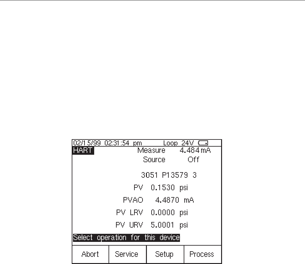
The Product recognizes and identifies the HART transmitter. When used with a
Model 3051, the Product shows:
qb20s.bmp
Figure 14. Active Device Screen
The Active Device screen gives this data for all HART transmitters, supported or
generic:
• Poll address (if not 0)
• Model number and Tag ID
• PV (Primary Variable)
• PVAO (digital representation of the Analog Output)
• PV LRV (PV Lower Range Value)
• PV URV (PV Upper Range Value)
• Softkeys for accessing HART operation menus
8. Communication to the HART transmitter has been established if step seven has
been completed. The Product has passed the HART mode verification test.
9. If the calibrator does not recognize the transmitter, the test has failed and Product
repair is necessary. Speak to your nearest approved Fluke Service Center for
servicing.
753/754
Calibration Manual
32
10. Disconnect all test equipment.
Fluke 75X
gks43.eps
Figure 15. HART Mode Verification Connections
Calibration
Calibration is necessary only if the UUT does not pass verification. Always re-verify
after calibration.
Calibration for the Product is done with internal software. There are no physical
adjustments (except for three potentiometers used for common-mode error, explained
later in this chapter). The subsequent instructions for calibration are minimal because of
the built-in guided procedures. The internal software routines give step-by-step prompts
for the correct stimulus or measurement. The guided procedures also illustrate which
terminals (jacks) to use when you apply a stimulus, reading a measurement, or which
terminals must be to be shorted with jumpers. Follow the instructions carefully to
complete each calibration routine.
Equipment Required for Calibration
The necessary accuracy of the source or measurement does not always correspond to the
number of decimal places indicated on the UUT’s display. For example, if you calibrate
Frequency Measure, when the display requests a source value of 5.00000 V at
1.00000 kHz, the necessary accuracies are not of that magnitude. Use the measurement
and source equipment suggested at the start of the Performance Verification Test.
Calibration Status Indicator
The calibration display is accessed by when you push s and then the Prev. Page
softkey. At the top of the display is the Calibration Status followed by a number. This
number moves forward after each subroutine is completed and the new constants are
kept. When you do a complete calibration, the Product moves the Calibration Status by 4.
Because the Calibration Status number is changed only by a re-calibration, it can be used
to make sure that previous calibration constants have not been changed.
How to Enter Calibration
In the calibration setup screen, push W to calibrate. The calibration screen requests
a password, 1234 is the default. After you put in the password, push Z to continue.
The password is user-settable.

Documenting Process Calibrator
Calibration
33
On the calibration screen, the step that has bolded text is the selected step.
Set Calibration Date sets the date that the Product shows for calibration at start-up. In
most instances this is the date that the Product last passed the Performance Verification.
There are four adjustment procedures:
• Adjust Source
• Adjust Loop
• Adjust Measure
• Adjust Thermocouple
Each of these items shows the last time this step was competed.
• When you push the Exit softkey, the Product goes out of Calibration mode and
starts.
• When you push the Change Calibration Password softkey the screen
changes to the password screen.
• When you push the Continue softkey, the Product continues with the selected
step.
Calibration Constant Out of Bounds
If one or more of the calibration stimuli (or measurements) is out of range during a
calibration routine, or the cabling is incorrect, the message [Error - Calibration Constant
Out of Bounds] shows at the end of the routine. A general fault with the UUT can also be
indicated by this error. The fault has to be corrected before you do the full sub-routine.
How to Calibrate
Follow these general instructions for all calibrations:
• Operate the UUT on battery power. Make sure the battery is fully charged.
• Let each piece of calibration equipment meet its specified warm up period.
• Let the UUT warm up a minimum of 10 minutes.
• Source is only powered when it is used. A separate warm up for 10 minutes is
necessary when you adjust source vdc, source ohms, source TC, source RTD, or
source Hz. When you do a full adjust, a 10-minute warm up pause at the start of
the volts dc source warms up the Product for all source steps.
• For each calibration, make sure the calibration equipment is stable and that the
“unsettled” annunciator on the UUT is not shown.
Continue:
1. Turn on the UUT.
2. Push s and then the Prev. Page softkey.
3. Push the Calibrate softkey to open the password screen
4. Input the password (the default password is 1234) and then push the Continue
softkey.
5. Use and D to move the black text to the step to run. Push the Continue
softkey to start a procedure
Each adjustment procedure will give connection instructions and signal levels
needed for the step.
6. When the display prompts you for an input of 100.000 mV dc but shows an range

753/754
Calibration Manual
34
of 90.0 ≤ 100.000 mV ≤ 110.0., apply the requested input, or apply an input in
the allowed range. Use the numeric keys to add the value. Push the Continue
softkey.
7. Apply the subsequent requested value as in step 5. Push the Continue softkey.
When you record a negative value, always start with ‘-’.
XWWarning
Some of the voltages required for calibration are dangerous. To
avoid injury or death from electric shock, do not touch live
conductors during high-voltage calibration. Put the source
device into Standby mode after each calibration step.
8. Continue to apply voltages as necessary. Make sure you follow the connection
instructions each time. Remember that the input jack configuration changes.
9. When you complete the last point in the subroutine, you are asked if you to keep
the new constants. If you keep the new constants, the calibration constants are
saved and the Calibration Status counter is incremented and the date is updated.
If you discard the constants at this point, the calibration has no effect, the
Calibration Status counter is not incremented, and the date does not change.
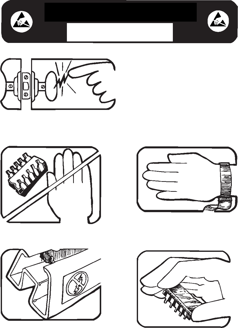
Some semiconductors and custom IC's can be
damaged by electrostatic discharge during
handling. This notice explains how you can
minimize the chances of destroying such devices
by:
1. Knowing that there is a problem.
2. Learning the guidelines for handling them.
3. Using the procedures, packaging, and
bench techniques that are recommended.
The following practices should be followed to minimize damage to S.S. (static sensitive) devices.
1. MINIMIZE HANDLING
2. KEEP PARTS IN ORIGINAL CONTAINERS
UNTIL READY FOR USE.
3. DISCHARGE PERSONAL STATIC BEFORE
HANDLING DEVICES. USE A HIGH RESIS-
TANCE GROUNDING WRIST STRAP.
4. HANDLE S.S. DEVICES BY THE BODY.
static awareness
A Message From
Fluke Corporation
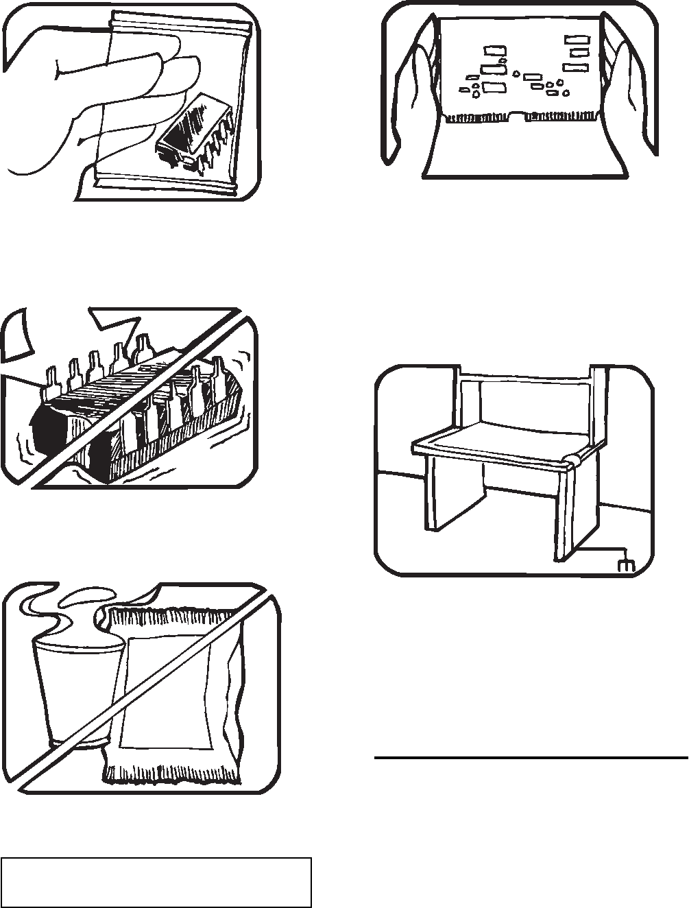
5. USE STATIC SHIELDING CONTAINERS FOR
HANDLING AND TRANSPORT.
6. DO NOT SLIDE S.S. DEVICES OVER
ANY SURFACE.
7. AVOID PLASTIC,VINYL AND STYROFOAM
IN WORK AREA.
8. WHEN REMOVING PLUG-IN ASSEMBLIES
HANDLE ONLY BY NON-CONDUCTIVE
EDGES AND NEVER TOUCH OPEN EDGE
CONNECTOR EXCEPT AT STATIC-FREE
WORK STATION. PLACING SHORTING
STRIPS ON EDGE CONNECTOR HELPS
PROTECT INSTALLED S.S. DEVICES.
9. HANDLE S.S. DEVICES ONLY AT A
STATIC-FREE WORK STATION.
10. ONLY ANTI-STATIC TYPE SOLDER-
SUCKERS SHOULD BE USED.
11. ONLY GROUNDED-TIP SOLDERING
IRONS SHOULD BE USED.
PORTIONS REPRINTED
WITH PERMISSION FROM TEKTRONIX INC.
AND GERNER DYNAMICS, POMONA DIV.
Dow Chemical

Documenting Process Calibrator
Maintenance
35
Maintenance
XWWarning
To prevent possible electrical shock, fire, or personal injury:
• Have an approved technician repair the Product.
• Do not operate the Product with covers removed or the case open.
Hazardous voltage exposure is possible.
• Remove the input signals before you clean the Product.
• Use only specified replacement parts.
Battery Replacement
Replace the battery when it no longer holds a charge for the rated interval. The battery
normally lasts for up to 300 charge/discharge cycles. To order a replacement battery, see
“Contacting Fluke” and “Replaceable Parts”.
Note
Spent batteries should be disposed of by a qualified recycler or hazardous
materials handler. Contact an authorized Fluke Service Center for
recycling information.
How to Clean the Product
Clean the Product and pressure modules with a soft cloth dampened with water or water
and mild soap.
WCaution
To prevent possible damage to the Product, do not use
solvents or abrasive cleansers.

753/754
Calibration Manual
36
Calibration Data
The date of the last calibration and verification shows on the calibration sticker and on
the calibration screen in Setup mode. The CAL. STATUS number on the sticker should
always match the Calibration Status number in the calibration screen. Calibration of the
Product is to be done by qualified personnel.
In Case of Difficulty
XWWarning
To avoid possible electric shock or personal injury, do not use
the Product if it operates abnormally. Protection may be
impaired. When in doubt, have the Product serviced.
If the display is blank or unreadable, but the beeper works when the Product is turned on,
make sure the brightness is correctly adjusted. To adjust the Intensity, see “Display
Intensity” in the Users Manual.
If the Product will not turn on, make sure the battery is not dead or disconnected from the
battery charger. If the Product receives power, the power button should be lit. If the
button is lit, but the Product does not power up, have the Product serviced. See “How to
Contact Fluke”.
Service Center Calibration or Repair
Calibration, repairs, or servicing not included in this manual must be done only by
qualified service personnel. If the Product fails, examine the battery pack first, and
replace it if necessary.
Make sure that you operate the Product in accordance with the instructions in this
manual. If the Product is faulty, send a description of the failure with the Product.
Pressure modules do not need to accompany the Product unless the module is faulty also.
Be sure to pack the Product securely, using the original shipping container if it is
available. See “How to Contact Fluke” and the Warranty Statement.

Documenting Process Calibrator
Replaceable Parts
37
Replaceable Parts
Table 18 lists the customer replaceable parts. Replacement parts can be ordered from
Fluke Corporation and its authorized representatives by using the part number. In the
event that the part ordered has been replaced by a new or improved part, the replacement
will be accompanied by an explanatory note and installation instructions, if necessary.
See Figure 16.
Table 18. Replacement Parts
Reference
Designator
754 754-SI 753 753-SI
Description
Part
Number
Part
Number
Part
Number
Part
Number
BT1 3409439 3409439 3409439 3409439 75x Battery, LI-ION, 7.2V,
4.4AH
DS1 3367520 3367520 3367520 3367520
LCD Module, 4.3 In Diag,
480xrgbx272 Pixels, LED
Backlight
H1-H6 1558745 1558745 1558745 1558745
Screw, 5-14,.750, Pan, Black
Chromate, Blunt Pt, Thread
Form
H7-H16 3783203 3783203 3783203 3783203
Screw, M3x0.5, 6mm, Pan
Head, Phillips, S-L Nylon
Patch
H17-H28 642931 642931 642931 642931
Screw, 4-14, .312, Pan,
Phillips, Thread Form, #3
Head
H29-H30 3469899 3469899 3469899 3469899 Nut, Slotted, M9 X 0.5
Thread
H30-H32 3469900 3469900 3469900 3469900 Washer, Locking, 12.5mm
od
MP3 3369304 3369304 3369304 3369304 Fluke-75x, TC Isothermal
PCA
MP4 3404752 3404752 3404752 3404752 Fluke-75x, Case Top
MP5 3404765 3404765 3404765 3404765 Fluke-75x, Case Bottom

753/754
Calibration Manual
38
Table 18. Replacement Parts (cont.)
Reference
Designator
754 754-SI 753 753-SI
Description
Part
Number
Part
Number
Part
Number
Part
Number
MP6, MP7 3404776 3404776 3404776 3404776 Fluke-75x, Connector
Cover
MP8 3404790 3404790 3404790 3404790 Fluke-75x, Tilt Stand
MP9 3948631 3948631 Fluke-753, Connector
Bracket, Right
MP9 3404803 3404803 Fluke-754, Connector
Bracket, Right
MP10 3404815 3404815 3404815 3404815 Fluke-75x, Connector
Bracket, Left
MP11 3404826 3404826 3404826 3404826 Fluke-75x, Retainer,
Isothermal Stopper
MP12 3404832 3404832 3404832 3404832 Fluke-75x, Stopper,
Isothermal
MP13 3977652 Fluke-753, Mask
MP13 3981533 Fluke-753, Mask, SI
MP13 3439164 Fluke-754, Mask
MP13 3977665 Fluke-754, Mask, SI
MP14 3405856 3405856 Fluke-753, Decal, Case
Top
MP14 3405856 3405856 Fluke-754, Decal, Case
Top
MP15 3977713 3977713 Fluke-753, Keypad
MP15 3369430 3369430 Fluke-754, Keypad
MP17-MP19 884259 884259 884259 884259 Input Receptacle
Insulator (Black)
MP20-MP22 884254 884254 884254 884254 Input Receptacle
Insulator (Red)
MP23 3478081 3478081 3478081 3478081 Fluke-75x, Foam, Dust
Seal

Documenting Process Calibrator
Replaceable Parts
39
Table 18. Replacement Parts (cont.)
Reference
Designator
754 754-SI 753 753-SI
Description
Part
Number
Part
Number
Part
Number
Part
Number
MP24 3477901 3477901 3477901 3477901 Fluke-75x, Battery
Compartment Foam Pad
MP25 3440115 3440115 3440115 3440115 Fluke-75x, LCD Shock
Absorber
MP44-MP45 3450124 3450124 3450124 3450124 Fluke-75x, TC Isothermal
Spring
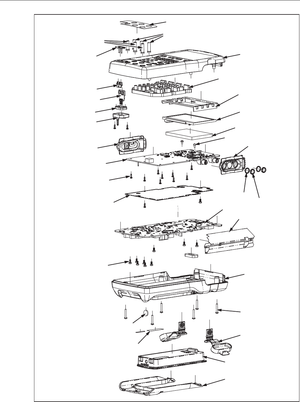
753/754
Calibration Manual
40
H31-H32
MP9
H29-H30
H33-H34
MP25
DS1
MP13
MP15
MP4
MP2
MP16
MP5
H1-H6
MP6 and MP7
MP8
BT1
MP14
MP20-MP22
MP17-MP19
MP43
MP44-MP45
MP3
MP12
MP11
MP10
MP1
H17-H28
H7-H16
MP35
MP36
MP24
gso16.eps
Figure 16. Parts

Documenting Process Calibrator
Accessories
41
Accessories
Accessories for the Product are listed in Table 19.
Table 19. Accessories
Batteries, Chargers and Adapters
BC7240 Battery Charger/Eliminator
BP7240 Li-Ion Battery Pack
Cases-Holsters
C700 Hard Case (700 Series)
C781 Soft Meter Case
C799 Soft Field Case
Test Leads Probes and Clips
AC220 SureGrip™ Alligator Clips
700TLK Fluke 700TLK Process Test lead kit
AC280 SureGrip™ Hook Clips
AC285 SureGrip™ Alligator Clips
TL940 Mini-Hook Test Leads
TL950 Mini-Pincer Test Leads
TP74 Lantern Tip Test Probes
TP920 Test Probe Adapter Set
754HCC Hart Communication Cable, 754
1671807 USB-A(M), USB-MINI-B(M), Shielded, 2M
944632 Test Lead, 1KV/CATII, 10cm, Black

753/754
Calibration Manual
42
