Fluke 789 Users Manual
2015-09-09
: Fluke Fluke-789-Users-Manual-806300 fluke-789-users-manual-806300 fluke pdf
Open the PDF directly: View PDF ![]() .
.
Page Count: 40

789
ProcessMeter™
Calibration Manual
September 2002, Rev.1, 3/13
© 2002-2013 Fluke Corporation. All rights reserved. Specifications are subject to change without notice.
All product names are trademarks of their respective companies.
LIMITED WARRANTY AND LIMITATION OF LIABILITY
Each Fluke product is warranted to be free from defects in material and workmanship under normal use and
service. The warranty period is three years and begins on the date of shipment. Parts, product repairs, and
services are warranted for 90 days. This warranty extends only to the original buyer or end-user customer of
a Fluke authorized reseller, and does not apply to fuses, disposable batteries, or to any product which, in
Fluke's opinion, has been misused, altered, neglected, contaminated, or damaged by accident or abnormal
conditions of operation or handling. Fluke warrants that software will operate substantially in accordance
with its functional specifications for 90 days and that it has been properly recorded on non-defective media.
Fluke does not warrant that software will be error free or operate without interruption.
Fluke authorized resellers shall extend this warranty on new and unused products to end-user customers
only but have no authority to extend a greater or different warranty on behalf of Fluke. Warranty support is
available only if product is purchased through a Fluke authorized sales outlet or Buyer has paid the
applicable international price. Fluke reserves the right to invoice Buyer for importation costs of
repair/replacement parts when product purchased in one country is submitted for repair in another country.
Fluke's warranty obligation is limited, at Fluke's option, to refund of the purchase price, free of charge repair,
or replacement of a defective product which is returned to a Fluke authorized service center within the
warranty period.
To obtain warranty service, contact your nearest Fluke authorized service center to obtain return
authorization information, then send the product to that service center, with a description of the difficulty,
postage and insurance prepaid (FOB Destination). Fluke assumes no risk for damage in transit. Following
warranty repair, the product will be returned to Buyer, transportation prepaid (FOB Destination). If Fluke
determines that failure was caused by neglect, misuse, contamination, alteration, accident, or abnormal
condition of operation or handling, including overvoltage failures caused by use outside the product’s
specified rating, or normal wear and tear of mechanical components, Fluke will provide an estimate of repair
costs and obtain authorization before commencing the work. Following repair, the product will be returned to
the Buyer transportation prepaid and the Buyer will be billed for the repair and return transportation charges
(FOB Shipping Point).
THIS WARRANTY IS BUYER'S SOLE AND EXCLUSIVE REMEDY AND IS IN LIEU OF ALL OTHER
WARRANTIES, EXPRESS OR IMPLIED, INCLUDING BUT NOT LIMITED TO ANY IMPLIED WARRANTY
OF MERCHANTABILITY OR FITNESS FOR A PARTICULAR PURPOSE. FLUKE SHALL NOT BE LIABLE
FOR ANY SPECIAL, INDIRECT, INCIDENTAL OR CONSEQUENTIAL DAMAGES OR LOSSES,
INCLUDING LOSS OF DATA, ARISING FROM ANY CAUSE OR THEORY.
Since some countries or states do not allow limitation of the term of an implied warranty, or exclusion or
limitation of incidental or consequential damages, the limitations and exclusions of this warranty may not
apply to every buyer. If any provision of this Warranty is held invalid or unenforceable by a court or other
decision-maker of competent jurisdiction, such holding will not affect the validity or enforceability of any other
provision.
Fluke Corporation
P.O. Box 9090
Everett, WA 98206-9090
U.S.A.
Fluke Europe B.V.
P.O. Box 1186
5602 BD Eindhoven
The Netherlands
11/99
i
Table of Contents
Title Page
Introduction ........................................................................................................ 1
How to Contact Fluke ........................................................................................ 1
Safety Information ............................................................................................. 2
Symbols ............................................................................................................. 3
Specifications ..................................................................................................... 4
Required Equipment .......................................................................................... 7
Basic Maintenance ............................................................................................. 8
Cleaning the ProcessMeter ............................................................................ 8
Replacing the Batteries .................................................................................. 8
Battery Life .................................................................................................... 9
Checking and Replacing the Fuses ................................................................ 10
Calibration Verification ..................................................................................... 10
Preparing to Perform Calibration Verification .............................................. 11
Loop Power ................................................................................................... 11
Current Sourcing ........................................................................................... 13
Current Measurement .................................................................................... 14
Checking the Diode Test Function ................................................................ 15
Checking the Continuity Test Function ......................................................... 17
Resistance Measurement Test ....................................................................... 18
DC Millivolts Measurement Test .................................................................. 20
DC Volts Measurement Tests ........................................................................ 21
AC Volts Measurement Test ......................................................................... 22
Frequency Measurement Test ........................................................................ 23
Calibration Adjustment ...................................................................................... 24
Preparing for Calibration Adjustment ........................................................... 24
AC Voltage Adjustment ................................................................................ 25
Frequency Adjustment ................................................................................... 26
DC Voltage Adjustment ................................................................................ 27
DC Millivolts Adjustment ............................................................................. 28
Ohms Adjustment .......................................................................................... 28
Diode Adjustment .......................................................................................... 29
Milliamps DC Adjustment ............................................................................ 29
Amps DC Adjustment ................................................................................... 30
Amps AC Adjustment ................................................................................... 30
Milliamps Output Adjustment ....................................................................... 30
Replacement Parts and Accessories ................................................................... 31

789
Calibration Manual
ii
iii
List of Tables
Table Title Page
1. International Symbols ............................................................................................ 3
2. Required Equipment and Software ........................................................................ 8
3. Typical Alkaline Battery Life ................................................................................ 9
4. Current Sourcing Test ............................................................................................ 13
5. DC mA Test ........................................................................................................... 15
6. DC Amp Test ......................................................................................................... 15
7. AC Amp Test ......................................................................................................... 15
8. Resistance Measurement Test Using a 5500A or 5520A Calibrator ...................... 19
9. DC mV Test ........................................................................................................... 20
10. DC Volts Test ......................................................................................................... 22
11. AC Volts Test ......................................................................................................... 22
12. Frequency Measurement Test ................................................................................ 23
13. Replacement Parts .................................................................................................. 32

789
Calibration Manual
iv
v
List of Figures
Figure Title Page
1. Replacing the Batteries and Fuses .......................................................................... 9
2. Verifying Loop Power ............................................................................................ 12
3. Current Sourcing Connections Using the HP 3458A ............................................. 13
4. Current Measurement Test Connections ................................................................ 14
5. Diode Test Connections ......................................................................................... 16
6. Continuity Test Connections .................................................................................. 17
7. Resistance Measurement Test Connections ........................................................... 18
8. DC mV Measurement Test Connections ................................................................ 20
9. AC/DC Voltage Measurement Test Connections .................................................. 21
10. Frequency Measurement Test Connections ........................................................... 23
11. Calibration Button Access ...................................................................................... 26
12. Replacement Parts .................................................................................................. 31

789
Calibration Manual
vi

1
Introduction
Warning
The information provided in this manual is for the use of qualified
personnel only. Do not perform the calibration verification tests or
calibration procedures described in this manual unless you are
qualified to do so.
Caution
The 789 ProcessMeter™ contains parts that can be damaged by static
discharge. No procedure in this document requires the case to be
opened. If you do so, follow the standard practices for handling static
sensitive devices.
The Calibration Manual for the 789 ProcessMeter (hereafter, also referred to as “the
ProcessMeter” or “the UUT”) provides the following information:
• Precautions and Safety information
• Specifications
• Basic maintenance (cleaning, replacing the batteries and fuses)
• Calibration verification test procedures
• Calibration adjustment procedures
• Accessories and replaceable parts
For complete operating instructions, refer to the 789 ProcessMeter Users Manual (on the
CD-ROM provided).
How to Contact Fluke
To contact Fluke, call one of the following telephone numbers:
• Technical Support USA: 1-800-44-FLUKE (1-800-443-5853)
• Calibration/Repair USA: 1-888-99-FLUKE (1-888-993-5853)
• Canada: 1-800-36-FLUKE (1-800-363-5853)
• Europe: +31 402-675-200
• Japan: +81-3-6714-3114
• Singapore: +65-6799-5566
• Anywhere in the world: +1-425-446-5500
Or, visit Fluke's website at www.fluke.com.
To register your product, visit http://register.fluke.com.
To view, print, or download the latest manual supplement, visit
http://us.fluke.com/usen/support/manuals.
Safety Information
A Warning identifies conditions and procedures that are dangerous to the user. A
Caution identifies conditions and procedures that can cause damage to the Product or the
equipment under test.
International symbols used on the Meter and in this manual are explained in Table 1.

789
Calibration Manual
2
Warning
To prevent possible electrical shock, fire, or personal injury:
• Read “Safety Information” before using the meter.
• Do not use the meter if it is damaged. Before using the meter, inspect the
case. Look for cracks or missing plastic. Pay particular attention to the
insulation surrounding the connectors.
• Make sure the battery door is closed and latched before operating the meter.
• Remove test leads from the meter before opening the battery door.
• Inspect the test leads for damaged insulation or exposed metal. Check test
lead continuity. Replace damaged test leads before using the meter.
• Do not use the meter if it operates abnormally. Protection may be impaired.
When in doubt, have the meter serviced.
• Do not operate the meter around explosive gas, vapor, or dust.
• Do not use in a damp or wet environment.
• Use only type AA batteries, properly installed in the meter case, to power the
meter.
• When servicing the meter, use only specified replacement parts.
• Use caution when working above 30 V ac rms, 42 V ac pk, or 60 V dc. Such
voltages pose a shock hazard.
• When using the probes, keep fingers behind the finger guards on the probes.
• Connect the common test lead before connecting the live test lead. When
disconnecting test leads, disconnect the live test lead first.
• Do not use AutoHold to determine if dangerous voltage is present. AutoHold
will not capture unstable or noisy readings.
• To avoid false readings, which could lead to possible electric shock or
personal injury, replace the battery as soon as the battery indicator ()
appears.
• Remove test leads from the meter before opening the battery door.
• Close and latch the battery door before using the meter.
• To avoid personal injury or damage to the meter, use only the specified
replacement fuse, 440 mA 1000 V fast-blow, Fluke PN 943121.
• Do not exceed the Measurement Category (CAT) rating of the lowest rated
individual component of a product, probe, or accessory.
• Do not use the TL175 or TP175 test probes in CAT III or CAT IV environments
without the probe tip fully extended and correct category rating visible in the
window.
• When the TL175 is used with instruments or other accessories, the lowest
category rating of the combination applies. One exception is when the probe
is used with the AC172 or AC175.
Caution
To prevent damage to the meter or the test equipment:
• Disconnect the power and discharge all high voltage capacitors
before testing resistance, diodes, or continuity.
• Use the proper terminals, switch setting, and range for the
measurement or sourcing applications.

ProcessMeter™
Symbols
3
Symbols
Symbols used on the ProcessMeter and in this calibration manual are explained in
Table 1.
Table 1. International Symbols
Symbol Meaning Symbol Meaning
Risk of danger. Important
information. See Manual. Hazardous voltage
Conforms to European Union
directives Conforms to relevant South Korean
EMC Standards
Meets Underwriters’ Laboratories
safety requirements Inspected and licensed by TÜV Product
Services
Conforms to relevant North
American Safety Standards Conforms to relevant Australian
Standards
Alternating current Earth ground
Direct current Fuse
Battery Double insulated
CAT II Measurement Category II is applicable to test and measuring circuits connected directly to
utilization points (socket outlets and similar points) of the low-voltage MAINS installation.
CAT III Measurement Category III is applicable to test and measuring circuits connected to the
distribution part of the building’s low-voltage MAINS installation.
CAT IV Measurement Category IV is applicable to test and measuring circuits connected at the
source of the building’s low-voltage MAINS installation.
This product complies with the WEEE Directive (2002/96/EC) marking requirements. The
affixed label indicates that you must not discard this electrical/electronic product in
domestic household waste. Product Category: With reference to the equipment types in
the WEEE Directive Annex I, this product is classed as category 9 "Monitoring and Control
Instrumentation" product. Do not dispose of this product as unsorted municipal waste. Go
to Fluke’s website for recycling information.

789
Calibration Manual
4
Specifications
All specifications apply from +18 °C to +28 °C unless stated otherwise.
All specifications assume a 5-minute warm-up period.
The standard specification interval is 1 year.
Note
“Counts” refers to the number of increments or decrements of the least
significant digit.
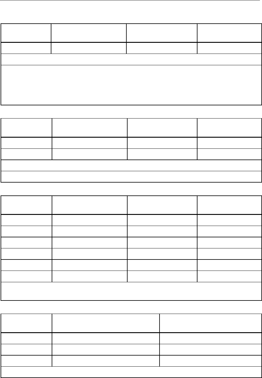
DC Volts Measurement
Range (V dc) Resolution Accuracy, ±(% of Reading + Counts)
4.000 0.001 V 0.1 % + 1
40.00 0.01 V 0.1 % + 1
400.0 0.1 V 0.1 % + 1
1000 1 V 0.1 % + 1
Input impedance: 10 M
Ω
(nominal), <100 pF
Normal mode rejection ratio: >60 dB at 50 Hz or 60 Hz
Common mode rejection ratio: >120 dB at dc, 50 Hz, or 60 Hz
Overvoltage protection: 1000 V
DC Millivolts Measurement
Range (mV dc) Resolution Accuracy, ±(% of Reading + Counts)
400.0 0.1 mV 0.1 % + 2
AC Volts Measurement
Range (ac) Resolution
Accuracy, ±(% of Reading + Counts)
50 Hz to 60 Hz 45 Hz to 200 Hz 200 Hz to 500 Hz
400.0 mV 0.1 mV 0.7 % + 4 1.2 % + 4 7.0 % + 4
4.000 V 0.001 V 0.7 % + 2 1.2 % + 4 7.0 % + 4
40.00 V 0.01 V 0.7 % + 2 1.2 % + 4 7.0 % + 4
400.0 V 0.1 V 0.7 % + 2 1.2 % + 4 7.0 % + 4
1000 V 1 V 0.7 % + 2 1.2 % + 4 7.0 % + 4
Specifications are valid from 5 % to 100 % of amplitude range.
AC conversion: true rms
Maximum crest factor: 3 (between 50 and 60 Hz)
For non-sinusoidal waveforms, add
±
(2 % reading + 2 % f.s.) typical
Input impedance: 10 M
Ω
(nominal), <100 pF, ac-coupled
Common mode rejection ratio: >60 dB at dc, 50 Hz, or 60 Hz
ProcessMeter™
Specifications
5
AC Current Measurement
Range
45 Hz to 2 kHz
Resolution Accuracy,
±(% of Reading + Counts)
Typical Burden
Voltage
1.000 A (Note) 0.001 A 1 % + 2 1.5 V/A
Note: 440 mA continuous, 1 A 30 seconds maximum
Specifications are valid from 5 % to 100 % of amplitude range.
AC conversion: true rms
Maximum crest factor: 3 (between 50 and 60 Hz)
For non-sinusoidal waveforms, add
±
( 2 % reading + 2 % f.s.) typical
Overload protection 440 mA, 1000 V fast-blow fuse
DC Current Measurement
Range Resolution Accuracy
±(% of Reading + Counts)
Typical Burden
Voltage
30.000 mA 0.001 mA 0.05 % + 2 14 mV/mA
1.000 A (Note) 0.001 A 0.2 % + 2 1.5 V/A
Note: 440 mA continuous, 1 A 30 seconds maximum
Overload protection: 440 mA, 1000 V fast-blow fuse
Ohms Measurement
Range Resolution Measurement Current
Accuracy
±(% of Reading + Counts)
400.0 Ω 0.1 Ω 220 μA 0.2 % + 2
4.000 kΩ 0.001 kΩ 60 μA 0.2 % + 1
40.00 kΩ 0.01 kΩ 6.0 μA 0.2 % + 1
400.0 kΩ 0.1 kΩ 600 nA 0.2 % + 1
4.000 MΩ 0.001 MΩ 220 nA 0.35 % + 3
40.00 MΩ 0.01 MΩ 22 nA 2.5 % + 3
Overload protection: 1000 V
Open circuit voltage: <3.9 V
Frequency Counter Accuracy
Range Resolution Accuracy
±(% of Reading + Counts)
199.99 Hz 0.01 Hz 0.005 % + 1
1999.9 Hz 0.1 Hz 0.005 % + 1
19.999 kHz 0.001 kHz 0.005 % + 1
Display updates 3 times/second at >10 Hz

789
Calibration Manual
6
Frequency Counter Sensitivity
Input Range
Minimum Sensitivity (rms Sinewave)
5 Hz to 5 kHz*
AC DC
(approximate trigger level 5 % of full scale)
400 mV 150 mV (50 Hz to 5 kHz) 150 mV
4 V 1 V 1 V
40 V 4 V 4 V
400 V 40 V 40 V
1000 V 400 V 400 V
*Usable 0.5 Hz to 20 kHz with reduced sensitivity.
106 VHz max
Diode Test and Continuity Test
Diode test indication: Displays voltage drop across device, 2.0 V full scale. Nominal
test current 0.2 mA at 0.6 V. Accuracy ±(2 % + 1 count).
Continuity test indication: Continuous audible tone for test resistance <100 Ω
Open circuit voltage: <2.9 V
Short circuit current: 220 μA typical
Overload protection: 1000 V rms
Loop Power Supply
Loop Power Supply: Minimum 24 V@ 24 mA into 1200 Ω load
DC Current Output
Source mode:
Span: 0 mA or 4 mA to 20 mA, with overrange to 24 mA
Accuracy: 0.05 % of span[1] (span: 0 to 20 mA)
Compliance voltage: 28 V with battery voltage > ~4.5 V
[1] 0.1 x specified accuracy per °C for temperatures <18 °C or >28 °C
Simulate Mode:
Span: 0 mA or 4 mA to 20 mA, with overrange to 24 mA
Accuracy: 0.05 % of span[1] (span: 0 to 20 mA)
Loop voltage: 24 V nominal, 48 V maximum, 15 V minimum
Compliance voltage: 21 V for 24 V supply
Burden voltage: <3 V
[1] 0.1 x specified accuracy per °C for temperatures <18 °C or >28 °C

ProcessMeter™
Required Equipment
7
General Specifications
Maximum voltage applied between
any jack and earth ground ..................... 1000 V
Battery Type ............................................ 1.5 V, 0-15 mA, AA, Alkaline
Storage temperature .............................. -40 °C to 60 °C
Operating temperature ........................... -20 °C to 55 °C
Operating altitude ................................... 2000 meters maximum
Frequency Overload Protection ............ 106 V Hz max
Temperature coefficient ......................... 0.05 x specified accuracy per °C for
temperatures <18 °C or >28 °C
0.1 x specified accuracy per °C for
temperatures <18 °C or >28 °C
Relative humidity .................................... 95 % up to 30 °C, 75 % up to 40 °C, 45 % up to
50 °C, and 35 % up to 55 °C
Vibration .................................................. Random 2g, 5 to 500 Hz
Shock ....................................................... 1 meter drop test
Power requirements ............................... Four AA batteries (alkaline recommended)
Size ........................................................... 10.0 cm X 20.3 cm X 5.0 cm (3.94 in X 8.00 in
X 1.97 in)
Weight ...................................................... 610 g (1.6 lb)
Safety ....................................................... IEC 61010-1: 600 V CAT IV / 1000 V CAT III,
Pollution Degree 2
Electromagnetic Environment .............. IEC 61326-1: Portable
Electromagnetic Compatibility .............. Accuracy for all ProcessMeter functions is not
specified in RF field >3V/m
Applies to use in Korea only ................. Class A Equipment (Industrial Broadcasting &
Communication Equipment[1]
[1] .. This product meets requirements for industrial (Class A) electromagnetic wave equipment
and the seller or user should take notice of it. This equipment is intended for use in
business environments and not to be used in homes.
Required Equipment
Equipment and software required to perform the procedures in this manual are identified
in Table 2.
If the recommended equipment model is not available, in some cases other equipment can
be substituted as long as it meets the specifications indicated.
Warning
To avoid safety hazards and equipment damage during the calibration
procedure, use the specified calibration equipment listed in Table 2.
Using unspecified equipment can jeopardize the calibration
verification test and pose safety hazards.
Note
Unless otherwise indicated, all connection diagrams for the calibration
verification tests in this manual showing a calibrator or digital multimeter
use a Fluke 5500A calibrator or Agilent 3458A.
If you are using a different calibrator or DMM, make the connections
appropriate for that instrument.

789
Calibration Manual
8
Table 2. Required Equipment and Software
Equipment Minimum Specifications Recommended Model
Calibration Source No Substitute Fluke Model 5500A
Digital Process Meter or
Digital Process Calibrator
No Substitute Fluke 787 ProcessMeter
741,743, or 744 Process
Calibrator
Digital Multimeter No Substitute Agilent 3458A
Test Leads, low leakage,
RG-58/U type
Leakage resistance > than 1.0 x 10¹³ Ω at
45 °C and 75 % relative humidity
Fluke 5440A-7002 Low
Thermal Test Leads
1-kΩ shunt 1 kΩ, 1 %, 2 watts, Low TC is preferable ---
Basic Maintenance
Cleaning the ProcessMeter
Warning
To avoid electrical shock or damage, never allow water inside the
case of the ProcessMeter.
If the ProcessMeter requires cleaning, wipe it down with a cloth that is lightly dampened
with water or a mild detergent.
Caution
Do not use aromatic hydrocarbons, chlorinated solvents, or methanol-
based fluids when wiping down the ProcessMeter. To avoid damaging
the case, never apply solvents to the case of the ProcessMeter.
Replacing the Batteries
Warning
To avoid electrical shock:
• Remove test leads from the ProcessMeter before opening the
battery compartment door.
• Close and latch the battery compartment door before using the
ProcessMeter.
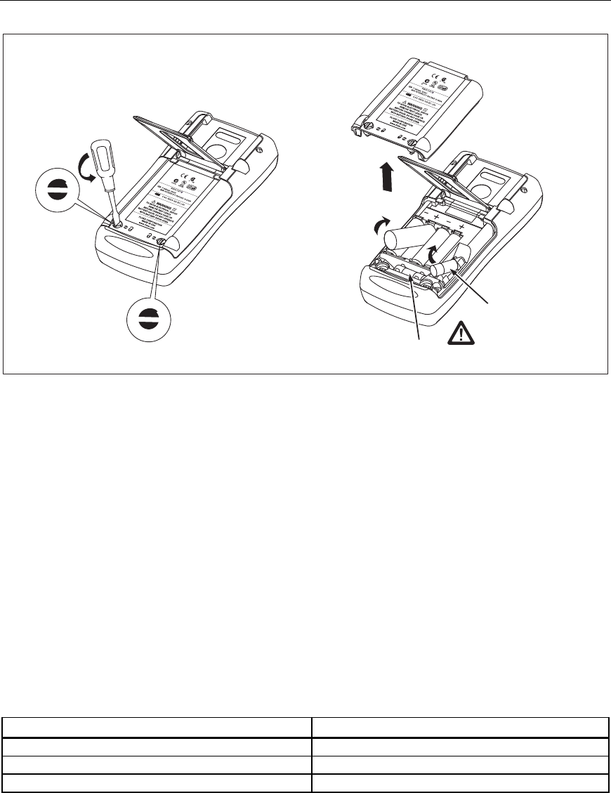
Replace the batteries as follows. Refer to Figure 1. Use four AA alkaline batteries.
1. Remove the test leads and turn the ProcessMeter OFF.
2. With a standard blade hand screwdriver, turn each battery compartment door screw
counterclockwise so that the slot is parallel with the screw picture molded into the
case.
3. Lift off the battery compartment door.
4. Remove the ProcessMeter's batteries.
5. Replace with four new AA alkaline batteries.
6. Reinstall the battery compartment door and tighten screws.
ProcessMeter™
Basic Maintenance
9
F2
F1
anw037.eps
Figure 1. Replacing the Batteries and Fuses
Battery Life
Warning
To avoid false readings, which can lead to possible electric shock or
personal injury, replace the batteries as soon as the low battery
indicator () appears.
The ProcessMeter is powered by four AA alkaline batteries.
Table 3 shows typical alkaline battery life. To preserve battery life:
• Use current simulation instead of sourcing when possible.
• Avoid using the backlight.
• Do not disable the automatic power-off feature.
• Turn the ProcessMeter off when not in use.
Table 3. Typical Alkaline Battery Life
ProcessMeter Operation Hours
Measuring any parameter 140
Simulating Current 140
Sourcing 12 mA into 500 Ω 10

789
Calibration Manual
10
Checking and Replacing the Fuses
Warning
To avoid personal injury or damage to the ProcessMeter, use only the
specified replacement fuse, 440 mA 1000 V fast-blow, Fluke PN
943121.
Both current input jacks are fused with separate 440 mA fuses. To determine if a fuse is
blown:
1. Turn the rotary function switch to W.
2. Plug the black test lead into COM, and the red test lead into the Ac input.
3. Using an ohmmeter, check the resistance between the ProcessMeter test leads. If the
resistance is about 1 Ω, the fuse is good. An open reading means that fuse F1 is
blown.
4. Move red test lead to .
5. Using an ohmmeter, check the resistance between the ProcessMeter test leads. If the
resistance is about 14 Ω, the fuse is good. An open means that fuse F2 is blown.
If a fuse is blown, replace it as follows. Refer to Figure 1 as necessary:
1. Remove the test leads from the ProcessMeter and turn the ProcessMeter OFF.
2. With a standard blade hand screwdriver, turn each battery compartment door screw
counterclockwise so that the slot is parallel with the screw picture molded into the
case.
3. Remove either fuse by gently prying one end loose, then sliding the fuse out of its
bracket.
4. Replace the blown fuse(s).
5. Replace the battery compartment door. Secure the door by turning the screws one-
quarter turn clockwise.
Calibration Verification
Warning
Some of the calibration verification tests involve the use of high
voltages and should be performed by qualified personnel only.
To avoid electrical shock, always place the calibrator in the Standby
(STBY) mode between tests and before handling the test connections
or test cables.
Calibration verification tests confirm the complete functionality of the ProcessMeter and
check the accuracy of each ProcessMeter function against its specifications. If the
ProcessMeter fails any calibration verification test, it needs calibration adjustment or
repair.
The ProcessMeter’s performance and accuracy are specified for one year after calibration
at operating temperatures of +18 °C to +28 °C (64 °F to 82 °F), in relative humidity to
90 %. The specifications assume the ProcessMeter has been warmed up for 5 minutes
before use.
To perform the calibration verification tests, it is not necessary to open the case; no
adjustments are necessary. Merely make the required connections, source the designated

ProcessMeter™
Calibration Verification
11
values, and determine if the reading on the ProcessMeter or the multimeter falls within
the acceptable range indicated.
These calibration verification test procedures assume that the person performing the tests
has read the 789 Users Manual, knows how to select functions and ranges on the
ProcessMeter, and knows how to operate the required equipment.
Note
Calibration verification tests for the ProcessMeter can be performed
manually, or they can be computer-automated (using Fluke’s MET/CAL
Calibration Software). This document provides the procedures necessary to
perform the calibration verification test manually.
Preparing to Perform Calibration Verification
Note
Throughout the calibration verification tests, “UUT” (unit under test)
refers to the ProcessMeter; the word “multimeter” is reserved for the
digital multimeter identified in the required equipment listed in Table 2.
Unless otherwise indicated, all connection diagrams for the calibration
verification tests in this manual showing a calibrator or digital multimeter
use a Fluke 5500A calibrator or HP 3458A.
If using a different calibrator or DMM make the connections appropriate
for your instrument.
To prepare the UUT for the calibration verification tests:
1. Make sure that the required equipment is available (see Table 2).
2. Make sure that the fuses in the UUT are intact. See “Checking and Replacing a Fuse”
earlier in this manual.
3. Make sure the UUT has fresh batteries. See “Replacing the Batteries” earlier in this
manual.
4. Warm up the calibrator and multimeter as required by their specifications.
5. Remove all input cables from the front of the UUT.
6. Make sure that the UUT is in a stable ambient temperature between 18 °C and 28 °C
(64.4 °F and 82.4 °F) and that it has been warmed up for 5 minutes.
789
Calibration Manual
12
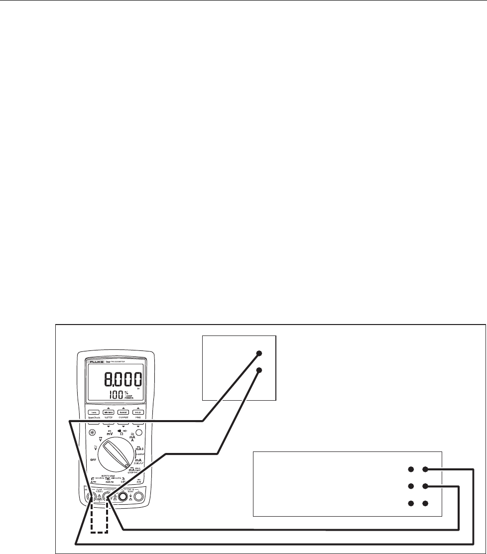
Loop Power
1. Enable the dc volts autorange function of the HP3458A multimeter.
2. Turn the rotary knob of the UUT to LOOP POWER.
3. Measure the open circuit voltage of the UUT and verify it is >29.8 V and <32 V.
4. Press J (BLUE) on the UUT to enable the 250 Ω HART resistor.
5. Repeat step 3.
6. Disable the 250 Ω HART resistor by pressing J (BLUE).
7. Connect the 1-kΩ shunt across SOURCE + and SOURCE - of the UUT.
8. Measure the loaded down voltage and verify it is >23.8 V and <32 V, see Figure 2.
9. Remove the 1-kΩ shunt.
10. Disconnect the UUT from the multimeter and turn the UUT off.
11. Select the dc current function on the multimeter and set it to the 1-amp range (a 0.1 Ω
shunt is used in the 1-amp range).
12. Connect the current input terminals of the multimeter to the SOURCE + and
SOURCE - terminals of the UUT.
13. Turn the rotary knob of the UUT to LOOP POWER.
14. Verify the short circuit current is >25 mA and <35 mA.
HP 3458A
DC Volts Autorange
Function
1 k
W
Shunt
UUT
adm006F.EPS
Figure 2. Verifying Loop Power
ProcessMeter™
Calibration Verification
13
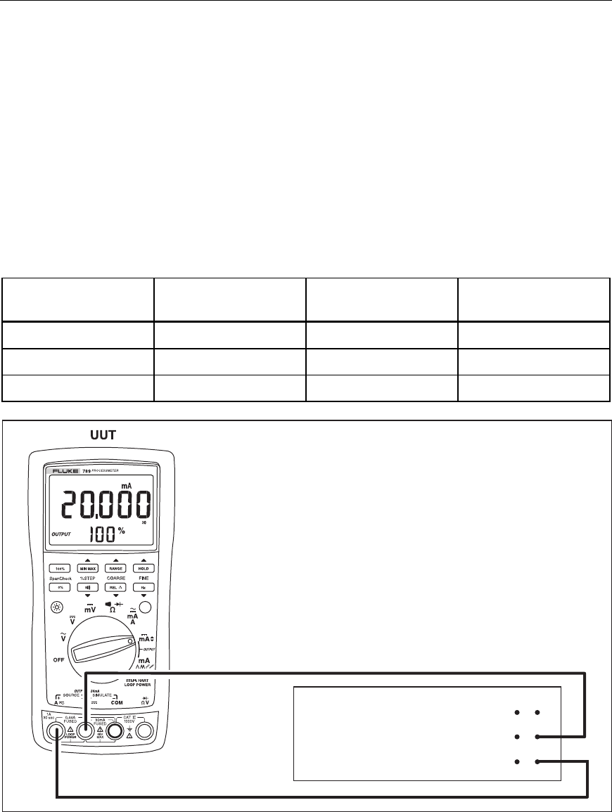
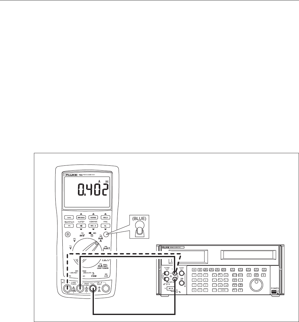
Current Sourcing
1. Put the calibrator in Standby (STBY) mode.
2. Connect the SOURCE + (A) and − (mA) terminals on the UUT to the current
terminals on the multimeter as shown in Figure 3.
3. Put the multimeter in the dc mA mode and manually select the 100 mA range. (Do
not allow the multimeter to autorange.)
4. Turn the UUT rotary switch in the OUTPUT X position.
5. Use the % STEP and COARSE keys on the UUT to apply the values shown in
Table 4 and compare the readings on the multimeter to the acceptable readings
shown.
Table 4. Current Sourcing Test
789 Range 789 Output Current Minimum Acceptable
Multimeter Reading
Maximum Acceptable
Multimeter Reading
No Range Switching 4.000 mA 3.990 mA 4.010 mA
No Range Switching 12.000 mA 11.990 mA 12.010 mA
No Range Switching 20.000 mA 19.990 mA 20.010 mA
HP 3458A
DC mA Function
100 mA Range
adm001F.EPS
Figure 3. Current Sourcing Connections Using the HP 3458A
789
Calibration Manual
14
Current Measurement
1. Put the calibrator in Standby (STBY) mode.
2. Put the UUT rotary switch in the Wposition.
3. Connect the calibrator to the COM and mA terminals on the UUT as shown in
Figure 4.
4. Apply the values from the calibrator shown in Table 5 and compare the readings on
the UUT to the acceptable readings shown.
5. Connect the calibrator to the COM and A terminals on the UUT.
6. Apply the values from the calibrator shown in Table 5 and Table 6 and compare the
readings on the UUT to the acceptable readings shown.
7. Press J (BLUE) on the UUT to toggle to ac amps.
8. Apply the values from the calibrator shown in Table 7 and compare the readings on
the UUT to the acceptable readings shown.
UUT
5500A
adm003F.EPS
Figure 4. Current Measurement Test Connections

ProcessMeter™
Calibration Verification
15
Table 5. DC mA Test
789 Range Calibrator
DC Current
Minimum Acceptable
Reading
Maximum Acceptable
Reading
No Range Switching 4.000 mA 3.996 mA 4.004 mA
No Range Switching 12.000 mA 11.992 mA 12.008 mA
No Range Switching 20.000 mA 19.988 mA 20.012 mA
Table 6. DC Amp Test
789 Range Calibrator
DC Current
Minimum Acceptable
Reading
Maximum Acceptable
Reading
No Range Switching 0.100 A 0.098 A 0.102 A
No Range Switching 0.400 A 0.397 A 0.403 A
Table 7. AC Amp Test
789 Range Calibrator AC Current
and Frequency
Minimum Acceptable
Reading
Maximum Acceptable
Reading
No Range Switching 0.100 A @ 60 Hz 0.097 A 0.103 A
No Range Switching 0.400 A @ 60 Hz 0.394 A 0.406 A
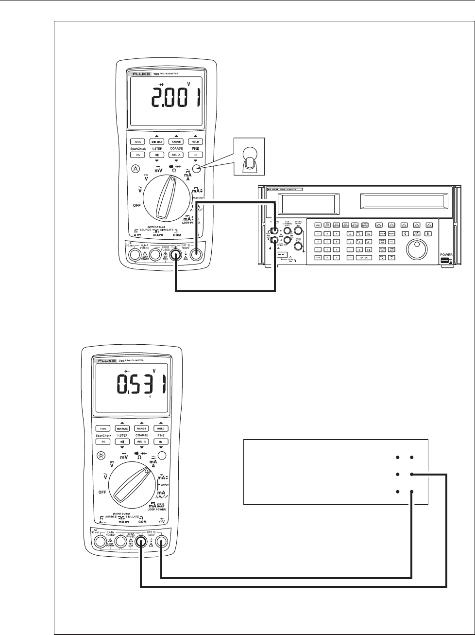
Checking the Diode Test Function
1. Put the calibrator in Standby (STBY) mode.
2. Turn the UUT rotary switch in the Vposition.
3. Press J (BLUE) to select diode test ().
4. Connect the calibrator to the COM and terminals on the UUT as shown in
Figure 5.
5. Apply 2.0 V dc from the calibrator.
6. The UUT should read between 1.959 V and 2.041 V.
7. Put the calibrator in Standby (STBY) mode; then disconnect the calibrator from the
UUT.
8. Put the multimeter in the dc mA (autorange) function.
9. Connect the current terminals of the multimeter to the COM and terminals on the
UUT.
10. The multimeter should read close to 0.2 mA. (There is no tolerance specification for
this current. This test just makes sure that the diode test current source is operating.)
789
Calibration Manual
16
5500A
HP 3458A
DC mA Autorange
Function
UUT
(BLUE)
adm007F.EPS
Figure 5. Diode Test Connections
ProcessMeter™
Calibration Verification
17
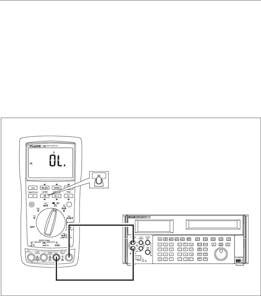
Checking the Continuity Test Function
1. Put the calibrator in Standby (STBY) mode, and turn the UUT rotary switch to the
V position.
2. Connect the calibrator to the COM and terminals on the UUT as shown in
Figure 6.
3. Press G (continuity beeper) on the UUT to select the continuity test.
4. Using the calibrator, apply a resistance output of 230 ± 20 Ω. The beeper should stay
off.
5. Using the calibrator, apply a resistance output of 120 ± 20 Ω. The beeper should turn
on.
5500A
UUT
adm008F.EPS
Figure 6. Continuity Test Connections
789
Calibration Manual
18
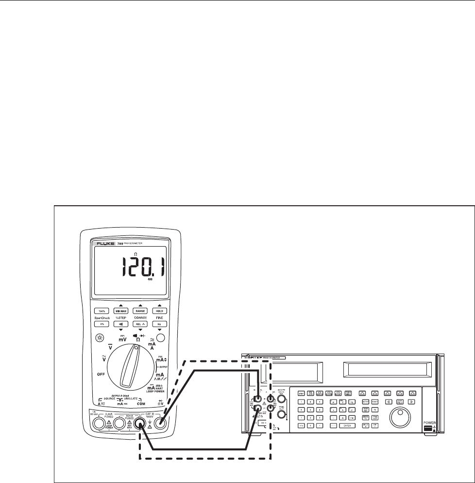
Resistance Measurement Test
1. Put the calibrator in Standby (STBY) mode.
2. Put the UUT rotary switch in the V position.
3. Connect the OUTPUT and SENSE leads of the calibrator to the UUT as shown by the
solid and dotted lines in Figure 7.
4. Apply the calibrator resistance values in Table 8 in the 789 400 Ω to 40 kΩ range.
Compare the readings on the UUT to the acceptable readings shown.
5. Change the connections to the UUT. Using the Fluke 5440A-7002 low thermal leads,
connect the calibrator to the UUT as shown by the solid lines in Figure 7.
6. Apply the rest of the calibrator resistance values in Table 8 (400 kΩ range and
above). Compare the readings on the UUT to the acceptable readings shown.
UUT
5500A
adm004F.EPS
Figure 7. Resistance Measurement Test Connections

ProcessMeter™
Calibration Verification
19
Table 8. Resistance Measurement Test Using a 5500A or 5520A Calibrator
789 Range Calibrator
Resistance
Calibrator
Compensation Mode
Minimum
Reading
Maximum
Reading
400 Ω 120 Ω 2-Wire 119.6 Ω 120.4 Ω
400 Ω 300 Ω 2-Wire 299.2 Ω 300.8 Ω
4 kΩ 1.2 kΩ 2-Wire 1.197 kΩ 1.203 kΩ
4 kΩ 3 kΩ 2-Wire 2.993 kΩ 3.007 kΩ
40 kΩ 12 kΩ 2-Wire 11.97 kΩ 12.03 kΩ
40 kΩ 30 kΩ 2-Wire 29.93 kΩ 30.07 kΩ
400 kΩ 120 kΩ OFF 119.7 kΩ 120.3 kΩ
400 kΩ 200 kΩ OFF 199.5 kΩ 200.5 kΩ
400 kΩ 300 kΩ OFF 299.3 kΩ 300.7 kΩ
4 MΩ 1.2 MΩ OFF 1.193 MΩ 1.207 MΩ
4 MΩ 3.0 MΩ OFF 2.986 MΩ 3.014 MΩ
40 MΩ 12 MΩ OFF 11.67 MΩ 12.33 MΩ
40 MΩ 30 MΩ OFF 29.22 MΩ 30.78 MΩ
789
Calibration Manual
20
DC Millivolts Measurement Test
1. Put the calibrator in Standby (STBY) mode.
2. Put the UUT rotary switch in the U position.
3. Connect the calibrator to the COM and terminals on the UUT as shown in
Figure 8.
4. Apply the values from the calibrator shown in Table 9 and compare the readings on
the UUT to the acceptable readings shown.
5500A
UUT
adm005F.EPS
Figure 8. DC mV Measurement Test Connections
Table 9. DC mV Test
789 Range Calibrator DC Voltage Minimum Reading Maximum Reading
No Range Switching 100 mV 99.8 mV 100.2 mV
No Range Switching 300 mV 299.6 mV 300.4 mV
ProcessMeter™
Calibration Verification
21
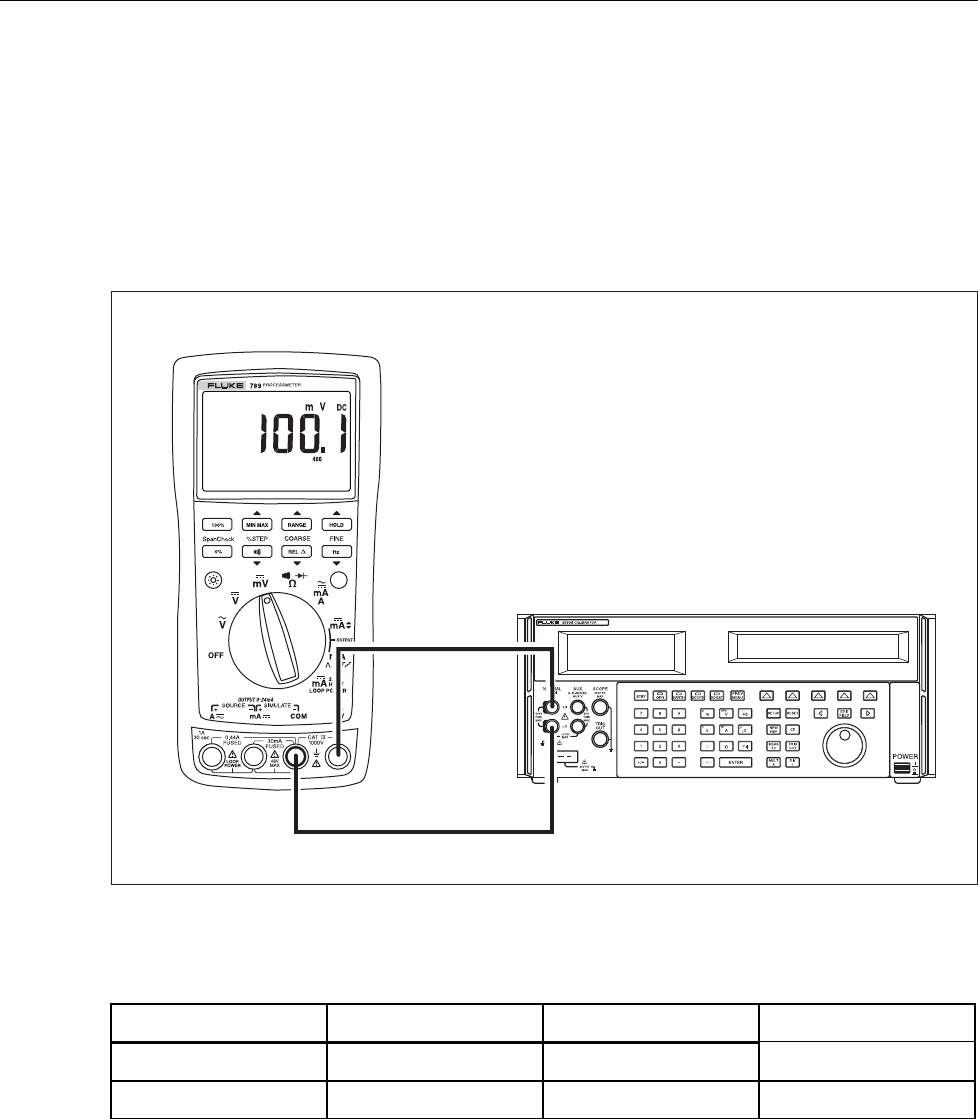
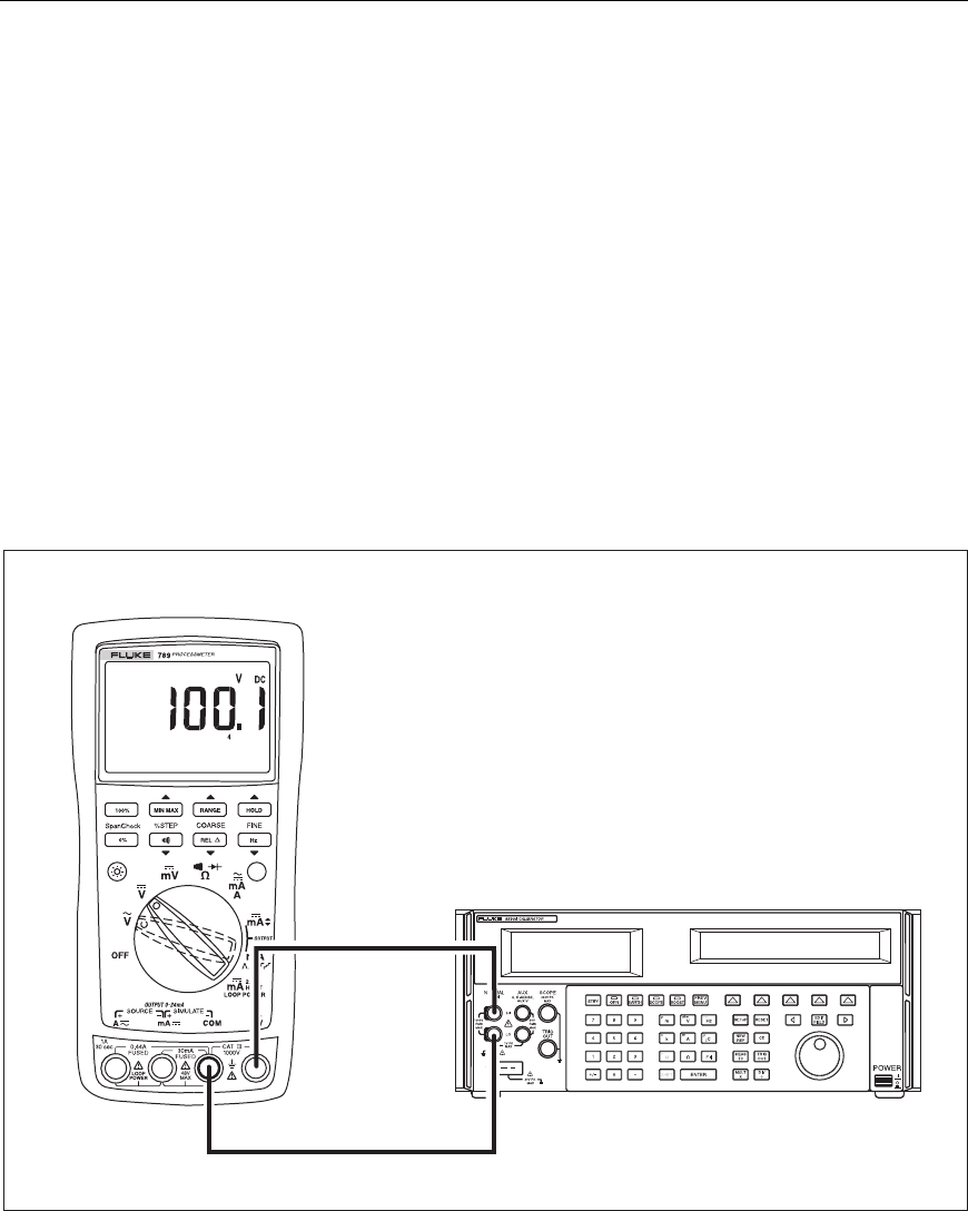
DC Volts Measurement Tests
Warning
To prevent possible electrical shock, fire, or personal injury:
• Some of the calibration verification tests involve the use of high
voltages and should be performed by qualified personnel only.
• Always place the calibrator in the Standby (STBY) mode between
tests and before handling the test connections or test cables.
1. Put the calibrator in Standby (STBY) mode.
2. Put the UUT rotary switch in the T position; select the autoranging mode.
3. Connect the calibrator to the COM and terminals on the UUT as shown in
Figure 9.
4. Apply the values from the calibrator shown in Table 10 and compare the readings on
the UUT to the acceptable readings shown.
5500A
UUT
adm009F.EPS
Figure 9. AC/DC Voltage Measurement Test Connections
789
Calibration Manual
22
Table 10. DC Volts Test
789 Range Calibrator DC Voltage Minimum Reading Maximum Reading
4 V dc 1 V 0.998 V 1.002 V
4 V dc 3 V 2.996 V 3.004 V
40 V dc 10 V 9.98 V 10.02 V
40 V dc 30 V 29.96 V 30.04 V
400 V dc 100 V 99.8 V 100.2 V
400 V dc 300 V 299.6 V 300.4 V
1000 V dc 100 V 99 101
1000 V dc 800 V 798 802
AC Volts Measurement Test
Warning
To prevent possible electrical shock, fire, or personal injury:
• Some of the calibration verification tests involve the use of high
voltages and should be performed by qualified personnel only.
• Always place the calibrator in the Standby (STBY) mode between
tests and before handling the test connections or test cables.
1. Put the calibrator in Standby (STBY) mode.
2. Put the UUT rotary switch in the S position.
3. Connect the calibrator to the COM and terminals on the UUT as shown in
Figure 9.
4. Apply the values from the calibrator shown in Table 11 and compare the readings on
the UUT to the acceptable readings shown.
Table 11. AC Volts Test
789 Range Calibrator Voltage and Frequency Minimum Acceptable
Reading
Maximum Acceptable
Reading
400 mV ac 100 mV @ 60 Hz 98.9 mV 101.1 mV
400 mV ac 300 mV @ 60 Hz 297.5 mV 302.5 mV
4 V ac 1 V @ 60 Hz 0.991 V 1.009 V
4 V ac 2 V @ 60 Hz 1.984 V 2.016 V
4 V ac 3 V @ 60 Hz 2.977 V 3.023 V
40 V ac 10 V @ 60 Hz 9.91 V 10.09 V
40 V ac 30 V @ 60 Hz 29.77 V 30.23 V
400 V ac 100 V @ 60 Hz 99.1 V 100.9 V
400 V ac 300 V @ 60 Hz 297.7 V 302.3 V
1000 V ac 100 V @ 60 Hz 97 103
1000 V ac 800 V @ 60 Hz 792 808
ProcessMeter™
Calibration Verification
23
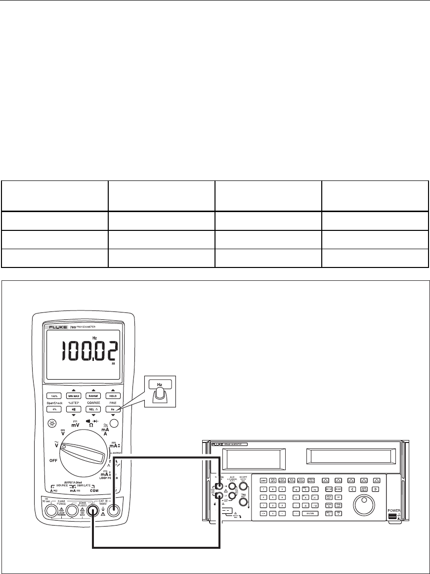
Frequency Measurement Test
1. Put the calibrator in Standby (STBY) mode.
2. Put the UUT rotary switch in the (ac volts) position.
3. Press h to toggle to the frequency measurement function.
4. Connect the calibrator to the COM and terminals on the UUT as shown in
Figure 10.
5. Apply the values from the calibrator shown in Table 12 and compare the readings on
the UUT to the acceptable readings shown.
Table 12. Frequency Measurement Test
789 Range Calibrator Voltage
and Frequency
Minimum Acceptable
Reading
Maximum Acceptable
Reading
199.99 Hz 5 V @ 100 Hz 99.98 Hz 100.02 Hz
1999.9 Hz 5 V @ 1000 Hz 999.8 Hz 1000.2 Hz
19.999 kHz 5 V @ 10 kHz 9.998 kHz 10.002 kHz
5500A
UUT
adm010F.EPS
Figure 10. Frequency Measurement Test Connections

789
Calibration Manual
24
Calibration Adjustment
The ProcessMeter is calibrated using a closed-case procedure.
Calibrate the ProcessMeter once a year to ensure that it performs according to its
specifications.
Preparing for Calibration Adjustment
Warning
To prevent possible electric shock, fire, or personal injury:
• Do not use the ProcessMeter if it looks damaged.
• Inspect the ProcessMeter for damage, especially around the input
terminals. Inspect the test leads and test connections for
damaged insulation or exposed metal.
• Look for cracks, missing plastic or damaged insulation. If damage
is detected, do not continue; contact Fluke to have the
ProcessMeter serviced.
• Make sure that the battery compartment door on the ProcessMeter
is closed and latched before using it.
• Check the test leads for continuity. Replace damaged test leads as
necessary.
• Do not use the ProcessMeter if it appears to operate abnormally.
Protection designed into the ProcessMeter might be impaired. If in
doubt, have the ProcessMeter serviced.
• To avoid electrical shock, always place the calibrator in the
Standby (STBY) mode between tests and before handling the test
connections or test cables.
• Some of the calibration adjustment procedures involve the use of
high voltages and should be performed by qualified personnel
only.

ProcessMeter™
Calibration Adjustment
25
Note
The calibration adjustment procedures assume that the person performing
them knows how to use the ProcessMeter and the required equipment. Do
not attempt to calibrate the ProcessMeter unless you are qualified to do so.
Throughout the following, “UUT” (unit under test) refers to the
ProcessMeter; the word “multimeter” is reserved for the digital multimeter
identified in the required equipment listed in Table 2.
Calibration adjustment should be performed in an RF field <1 V/m such as
a laboratory environment.
To prepare for calibration adjustment, do the following:
1. Make sure that you have the required equipment available (see Table 2).
2. Make sure that both fuses in the UUT are intact. See “Checking and Replacing the
Fuses” earlier in this manual.
3. Turn on and warm up the calibrator as required by its specifications.
4. Remove all input cables from the front of the UUT.
5. Make sure that the UUT is in an ambient temperature between 18 °C and 28 °C
(64.4 °F and 82.4 °F).
AC Voltage Adjustment
1. Connect the ProcessMeter to the volt/ohm output of the 5500A calibrator.
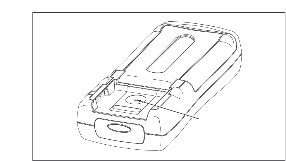
2. Turn the UUT’s switch to S.
3. The calibration button is located on the backside of the ProcessMeter, under the
Calibration Seal. Use a small probe to break the seal.
4. Press and hold the Calibration Button for approximately 2 seconds. The unit will
beep (see Figure 11).
Note
Pressing the Calibration Button puts the ProcessMeter into and out of
calibration mode. The ProcessMeter will remain in calibration mode until
the unit is turned off or the calibration button is pressed a second time.
CAL appears in the bottom display when the ProcessMeter is in calibration
mode.
5. Apply the voltages listed below as prompted by the ProcessMeter.
6. Press after each sourced value appears. Do not alter the sourced value while
the display reads Busy.
Applied voltages:
• 4 mV @ 60 Hz
• 40 mV @ 60 Hz
• 400 mV @ 60 Hz
• 4 V @ 60 Hz
• 40 V @ 60 Hz
• 400 V @ 60 Hz
• 1000 V @ 60 Hz
7. When Store is displayed, press to store the calibration value.
789
Calibration Manual
26
Calibration Button
aau04f.eps
Figure 11. Calibration Button Access
Frequency Adjustment
1. Connect the ProcessMeter to the volt/ohm output of the 5500A calibrator.
2. Turn the UUT’s switch to S.
3. Push h.
4. Press and hold the Calibration Button for approximately 2 seconds. The unit will
beep (see Figure 11).
Note
Pressing the Calibration Button puts the ProcessMeter into and out of
calibration mode. The ProcessMeter will remain in calibration mode until
the unit is turned off or the calibration button is pressed a second time.
CAL appears in the bottom display when the ProcessMeter is in calibration
mode.
5. Apply 4 V @ 5000 Hz.
6. Press after the sourced value appears. Do not alter the sourced value while the
display reads Busy.
7. When Store is displayed, press to store the calibration value.

ProcessMeter™
Calibration Adjustment
27
DC Voltage Adjustment
1. Connect the ProcessMeter to the volt/ohm output of the 5500A calibrator.
2. Turn the UUT’s switch to T.
3. Press and hold the Calibration Button for approximately 2 seconds. The unit will
beep (see Figure 11).
Note
Pressing the Calibration Button puts the ProcessMeter into and out of
calibration mode. The ProcessMeter will remain in calibration mode until
the unit is turned off or the calibration button is pressed a second time.
CAL appears in the bottom display when the ProcessMeter is in calibration
mode.
4. Press after each sourced value appears. Do not alter the sourced value while
the display reads Busy.
Applied voltages:
• 0 V
• 4 V
• 40 V
• 400 V
• 1000 V
5. When Store is displayed, press to store the calibration value.

789
Calibration Manual
28
DC Millivolts Adjustment
1. Connect the ProcessMeter to the volt/ohm output of the 5500A calibrator.
2. Turn the UUT’s switch to U.
3. Press and hold the Calibration Button for approximately 2 seconds. The unit will
beep (see Figure 11).
Note
Pressing the Calibration Button puts the ProcessMeter into and out of
calibration mode. The ProcessMeter will remain in calibration mode until
the unit is turned off or the calibration button is pressed a second time.
CAL appears in the bottom display when the ProcessMeter is in calibration
mode.
4. Apply 0 V. Press after the sourced value appears. Do not alter the sourced
value while the display reads Busy.
5. Apply 400 mV. Press after the sourced value appears. Do not alter the sourced
value while the display reads Busy.
6. When Store is displayed, press to store the calibration value.
Ohms Adjustment
1. Connect the ProcessMeter to the volt/ohm output of the 5500A calibrator.
2. Turn the UUT’s switch to V.
3. Press and hold the Calibration Button for approximately 2 seconds. The unit will
beep (see Figure 11).
Note
Pressing the Calibration Button puts the ProcessMeter into and out of
calibration mode. The ProcessMeter will remain in calibration mode until
the unit is turned off or the calibration button is pressed a second time.
CAL appears in the bottom display when the ProcessMeter is in calibration
mode.
4. Apply the resistances listed below. Press after each sourced value appears. Do
not alter the sourced value while the display reads Busy.
Applied resistances:
• 0 Ω
• 400 Ω
• 4 kΩ
• 40 kΩ
• 400 kΩ
• 4 MΩ
• 40 MΩ
5. When Store is displayed, press to store the calibration value.

ProcessMeter™
Calibration Adjustment
29
Diode Adjustment
1. Connect the ProcessMeter to the volt/ohm output of the 5500A calibrator.
2. Turn the UUT’s switch to V.
3. Press J (BLUE) to enter the diode function.
4. Press and hold the Calibration Button for approximately 2 seconds. The unit will
beep (see Figure 11).
Note
Pressing the Calibration Button puts the ProcessMeter into and out of
calibration mode. The ProcessMeter will remain in calibration mode until
the unit is turned off or the calibration button is pressed a second time.
CAL appears in the bottom display when the ProcessMeter is in calibration
mode.
Before applying 0 V dc, the 5500 must be range locked in the 3.3 V range.
Impedance of 330 mV range changes the 0 V point.
5. Apply 0 V dc. Press after the sourced value appears. Do not alter the sourced
value while the display reads Busy.
6. Apply 1 V dc. Press after the sourced value appears. Do not alter the sourced
value while the display reads Busy.
7. When Store is displayed, press to store the calibration value.
Milliamps DC Adjustment
1. Connect the ProcessMeter to the mA output of the 5500A calibrator.
2. Turn the UUT’s switch to W. Make sure the test leads are in the mA and COM
inputs.
3. Press and hold the Calibration Button for approximately 2 seconds. The unit will
beep (see Figure 11).
Note
Pressing the Calibration Button puts the ProcessMeter into and out of
calibration mode. The ProcessMeter will remain in calibration mode until
the unit is turned off or the calibration button is pressed a second time.
CAL appears in the bottom display when the ProcessMeter is in calibration
mode.
4. Apply 0 mA dc. Press after the sourced value appears. Do not alter the sourced
value while the display reads Busy.
5. Apply 30 mA dc. Press after the sourced value appears. Do not alter the
sourced value while the display reads Busy.
6. When Store is displayed, press to store the calibration value.

789
Calibration Manual
30
Amps DC Adjustment
1. Connect the ProcessMeter to the A output of the 5500A calibrator.
2. Turn the UUT’s switch to W. Make sure the test leads are in the A and COM jacks.
3. Press and hold the Calibration Button for 2 seconds (see Figure 11). The unit will
beep.
4. Apply 0 A dc. Press after the reading stabilizes.
5. Apply 1 A dc. Press after the reading stabilizes.
Caution
Remove 1 A from UUT promptly after storing calibration constant.
Fuse will blow after 30 seconds.
6. Press to store calibration constants.
Amps AC Adjustment
1. Connect the ProcessMeter to the A output of the 5500A calibrator.
2. Turn the UUT’s switch to W.
3. Press J (BLUE) to enter the A ac function.
4. Press and hold the Calibration Button for 2 seconds (see Figure 11). The unit will
beep.
5. Apply 0.05 A ac @ 60 Hz. Press after the reading stabilizes.
6. Apply 1 A ac. Press after the reading stabilizes.
7. Press to store calibration constants.
Caution
Remove 1 A from UUT promptly after storing calibration constant.
Fuse will blow after 30 seconds.
Milliamps Output Adjustment
1. Connect the ProcessMeter A output to the 3458 input.
2. UUT will output approximately 4 mA. Use the fine and coarse adjustments on the
UUT to get a 4.000 mA reading on the 3458.
3. Press after 4.000 mA reading is reached on the 3458.
4. UUT will output approximately 20 mA. Use the fine and coarse adjustments on the
UUT to get a 20.000 on the 3458.
5. Press after 20.000 mA reading is reached on the 3458.
6. Press to store calibration constants.
ProcessMeter™
Replacement Parts and Accessories
31
Replacement Parts and Accessories
Warning
To avoid personal injury or damage to the ProcessMeter, use only the
specified replacement fuse, 440 mA 1000 V fast-blow, Fluke PN 943121.
Note
When servicing the ProcessMeter, use only the replacement parts specified
here.
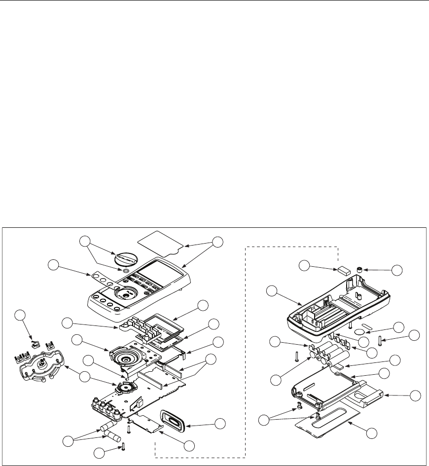
Replacement parts and some accessories are shown in Figure 12 and listed in Table 13.
Many more DMM accessories are available from Fluke. For a catalog, contact the nearest
Fluke distributor.
To find out how to order parts or accessories use the telephone numbers or addresses
shown in "Contacting Fluke."
18
26
17
22
23
30
27
19
29
28
24
25
20
21
9
4
12
5
6
8
10
7
3
2
16
15
14
13
11
1
anw005f.eps
Figure 12. Replacement Parts
789
Calibration Manual
32
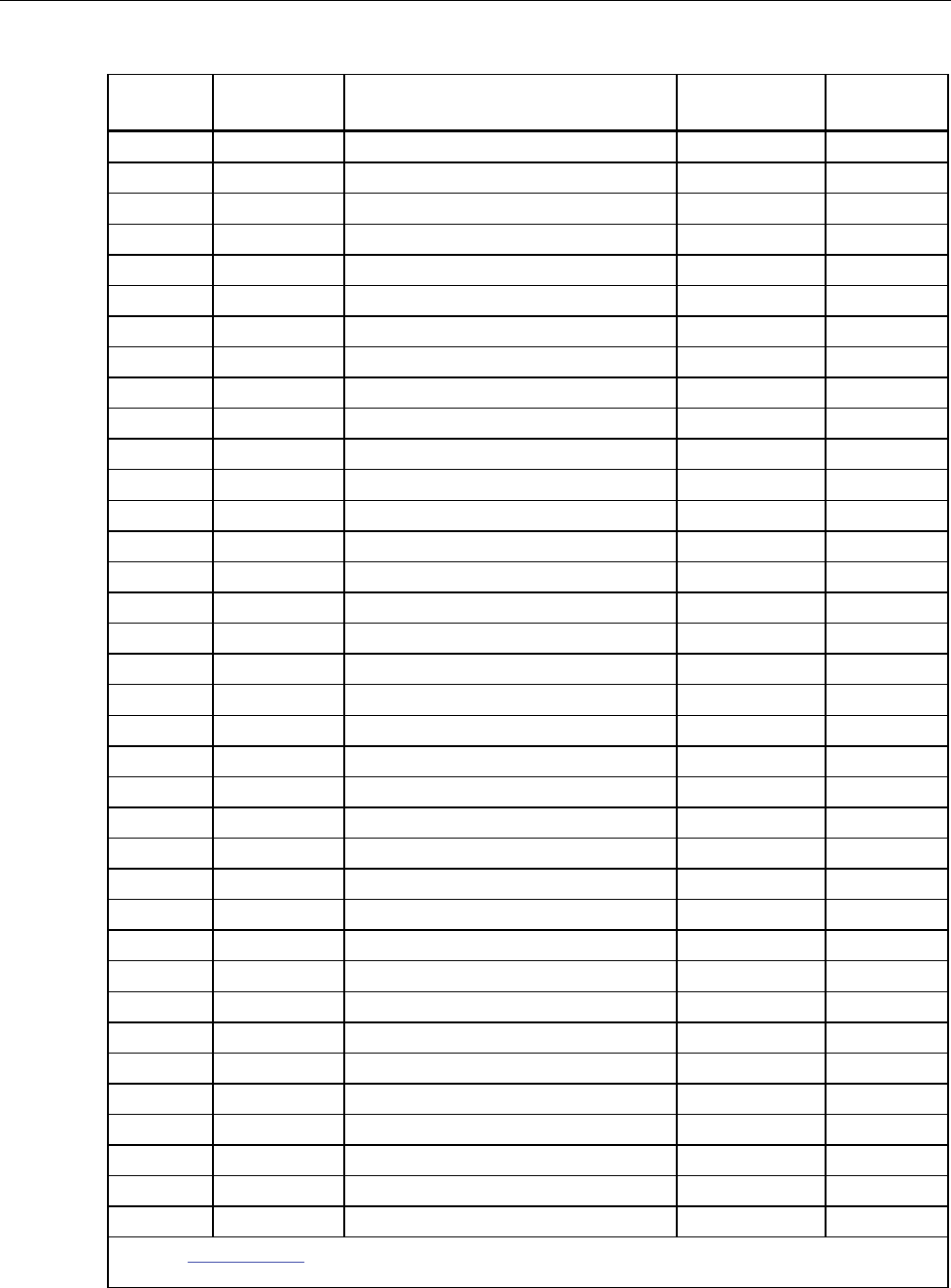
Table 13. Replacement Parts
Item
Number
Reference
Designator Description Fluke PN or
Model no. Quantity
MP14 Knob Assembly 658440 1
MP1 Top Case with Lens Protector 1622862 1
MP8 Decal, Top Case 1623923 1
DMP6 Keypad 1622951 1
EMP5 Top Shield 1622924 1
FMP47 Top Shield Contact 674853 1
GMP4 Contact Housing 1622913 1
HMP28-31 RSOB Contact 1567683 4
I! F1, F2 Fuse, 440 mA, 1000 V fast-blow 943121 2
JH7,8 PCB Screw 832220 2
KMP9 Bottom Shield 1675171 1
LMP12 IR Lens 658697 1
MMP40,41 LCD Connectors, Elastomeric 1641965 2
NMP7 Backlight/Bracket 1622960 1
OP1 LCD Display 1883431 1
PMP3 Mask 1622896 1
QMP50 Shock Absorber 878983 1
RMP11 Bottom Case 659042 1
SMP20 Battery Contact, Negative 658382 1
TBT1-4 Battery, 1.5 V, 0-15 mA, AA Alkaline 376756 4
UH1-2 Fasteners, Battery/Fuse Access Door 948609 2
VMP13 Tilt-Stand 659026 1
WMP15 Accessory Mount with Probe Holders 658424 1
XMP2 Access Door, Battery/Fuse 1622870 1
YMP46 Shock Absorber 674850 1
ZMP16-18 Battery Contacts Dual 666435 3
aMP19 Battery Contact, Positive 666438 1
bH3-6 Case Screws 1558745 4
cMP21 Calibration Label 948674 1
dMP22 Calibration Keypad 658689 1
- Not shown Test Leads variable[1] 1 (set of 2)
- Not shown Alligator Clips variable[1] 1 (set of 2)
- Not shown Test Lead Cap, Black 3986568 1
- Not shown Test Lead Cap, Red 3995524 1
- Not shown 789 Quick Reference 4276679 1
-Not shown CD-ROM (Contains Users Manual) 1636493 1
[1] See www.fluke.com for more information about the test leads and alligator clips available for your
region.
