Fluke 975 Application Note
2015-09-09
: Fluke Fluke-975-Application-Note-808548 fluke-975-application-note-808548 fluke pdf
Open the PDF directly: View PDF ![]() .
.
Page Count: 3

Application Note
Measuring air velocity with
the Fluke 975 AirMeter:
Using the velocity probe
From the Fluke Digital Library @ www.fluke.com/library
Air velocity is a key parameter in evaluating airflow sys-
tem performance. As part of basic testing, adjusting
and balancing of HVAC air distribution systems, most
HVAC technicians now use an anemometer to mea-
sure air velocity at grilles-registers-diffusers, within a
duct, or in open spaces.
Anemometers are typically very accurate tools,
especially at low velocities, but they must compensate
for air temperature, absolute pressure, and ambient
absolute pressure. The Fluke 975 AirMeter tool has an
accessory velocity probe that uses a thermal anemom-
eter to measure air velocity. A temperature sensor in
the probe tip compensates for air temperature, a sen-
sor in the meter reads absolute pressure, and ambient
absolute pressure is determined upon meter initializa-
tion. For users who prefer to calculate their own com-
pensation factors, the meter will also display air velocity
or volume at standard conditions.
This application note describes how to take accurate
air volume measurements within a duct, air measure-
ments at grilles-registers-diffusers, and other locations.
Air volumes within a duct
The ultimate goal of any duct
system is to move the required
air volume, while keeping all
other factors within acceptable
limits, and to deliver it in quanti-
ties and patterns that serve the
intended purpose: heating, cool-
ing, ventilating, exhausting, mix-
ing, humidifying, dehumidifying,
or otherwise conditioning the air
within a space. Velocity within
a duct is determined not only
by application, but also by how
the duct is designed. Key design
factors include: The level of
available static pressure that can
be overcome by the fan due to
friction losses and pressure drops
of devices within the air stream;
the cost of duct work; the space
available for duct work; and
acceptable noise levels.
To determine the air volume
delivered to all downstream ter-
minal devices, technicians use a
duct traverse. Duct traverses can
determine air volume in any duct
by multiplying average velocity
readings by the inside area of
the duct. Traverses in main ducts
measure total system air volume,
which is critical to HVAC system
performance, efficiency, and even
life expectancy. The difference
in air volumes between the main
supply duct traverse and the
main return duct traverse results
in outdoor air volume. A traverse
in run-outs is the most accurate
way to determine the air volume
delivered by the terminal device
(grille-register-diffuser). A tra-
verse in exhaust ducts reveals
exhaust air volume.
Measuring air velocity in a duct.
2 Fluke Corporation Measuring air velocity with the Fluke 975 AirMeter: Using the velocity probe
A duct traverse consists of a
number of regularly spaced air
velocity measurements through-
out a cross sectional area of
straight duct. Preferably, the
traverse should be located in a
straight section of duct with ten
straight duct diameters upstream
and three straight duct diam-
eters downstream of the traverse
plane, although a minimum of
five duct diameters upstream and
one duct diameter downstream
can give adequate results.
The number of measurements
taken across the traverse plane
depends on the size and geom-
etry of the duct. Most duct tra-
verses result in at least 18 to 25
velocity readings, with the num-
ber of readings increasing with
duct size. The industry accepted
measurement points across the
traverse are determined by the
Log-Tchebycheff rule for rectan-
gular duct, and by the Log-Linear
rule for round duct. Usually, tech-
nicians drill five to seven holes
on one side of rectangular ducts,
and two to three holes in round
ducts, in order for the telescop-
ing anemometer probe to access
the traverse points. To ensure
the anemometer is used in the
direction of calibration, align the
mark on the velocity probe tip
with the impact direction. When
extending the probe, align the
wand section with the handle to
help maintain the correct direc-
tion inside the duct.
Before taking measurements,
slide the protective sheath
toward the wand handle in
order to expose the sensors in
the probe tip. For volume flow
rate calculations, the Fluke
975 AirMeter™* will prompt for
rectangular or round duct, then
prompt for rectangular side
dimensions or round diameter.
Take the required number of
velocity readings one at a time
by pressing the “capture” key. If
a velocity reading is taken pre-
maturely, the Fluke 975 allows
you to re-take it. When all veloc-
ity readings are complete, the
AirMeter™ averages the readings
and multiplies by the duct cross
sectional area to get air volume,
both at standard conditions and
compensated for absolute pres-
sure and temperature.
The velocity readings (FPM)
are averaged and multiplied by
the inside area of the duct (sq ft)
which provides the air volume
(CFM).
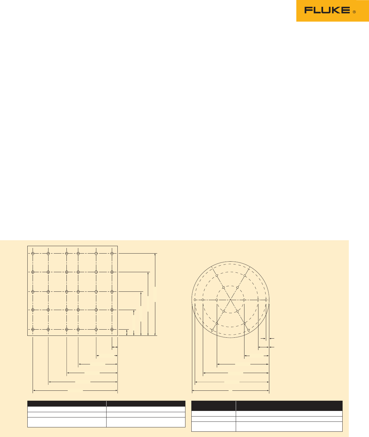
0.061 D
0.235 D
0.437 D
0.563 D
0.785 D
0.939 D
0.074 D
0.288 D
0.500 D
0.712 D
0.926 D
0.135 D
0.321 D
0.032 D
0.579 D
0.865 D
0.968 D
D
Patterns of holes drilled in rectangular and round ducts when conducting a duct traversal. Taken from ANSI/ASHRAE Standard 111-1988.
No. of points or traverse lines Position relative to inner wall
5 0.074, 0.238, 0.500, 0.712, 0.926
6 0.061, 0.235, 0.437, 0.563, 0.765, 0.939
70.053, 0.203, 0.366, 0.500, 0.534, 0.797,
0.947
No. of measuring
points per diameter Position relative to inner wall
6 0.032, 0.135, 0.321, 0.679, 0.865, 0.968
8 0.021, 0.117, 0.184, 0.345, 0.655, 0.816, 0.883, 0.981
10 0.019, 0.077, 0.153, 0.217, 0.361, 0.639, 0.783, 0.847, 0.923,
0.981
Q = V * A
Q = Air volume, CFM (cubic feet per minute)
or M3/s (cubic meters per second)
V = Velocity, FPM (feet per minute) or m/sec
(meters per second)
A = Area of duct, inside dimension of duct in
square feet or square meters
*For determining air velocity greater than 600 feet per minute
(FPM) within a duct, an HVAC technician may also use a Pitot-
static tube with an inclined manometer. Anemometers are the
preferred choice below 600 FPM and are quite acceptable at
higher velocities, too. The Fluke 975 AirMeter’s anemometer
measures over a range of 50 to 3000 fpm. In low pressure
duct systems where sound is a concern, such as residences
and health care facilities, velocity usually ranges from 400 to
900 FPM, while in high pressure duct systems, velocities can
approach 3,500 FPM.
0.061 D
0.235 D
0.437 D
0.563 D
0.785 D
0.939 D
0.074 D
0.288 D
0.500 D
0.712 D
0.926 D
0.135 D
0.321 D
0.032 D
0.579 D
0.865 D
0.968 D
D

3 Fluke Corporation Measuring air velocity with the Fluke 975 AirMeter: Using the velocity probe
Air measurements
at Grilles-Registers-
Diffusers (GRDs)
Supply air GRDs are selected and
positioned to deliver specified air
volume in velocities and patterns
that result in acceptable comfort
and ventilation within the occu-
pant zone. The occupant zone is
considered to be one foot from
walls and below head height.
Velocity from a supply GRD nor-
mally does not exceed 800 FPM,
and velocity into a return grille
should not exceed 400 FPM in
applications where noise would
be objectionable. Velocity must
be sufficient to mix the supply
air with the room air outside of
the occupant zone, while creat-
ing comfortable air patterns and
temperatures within the occu-
pant zone.
Throw is the distance the air
travels from a GRD before reach-
ing terminal velocity. Throw is
normally 75 % to 110 % of the
distance from the GRD to the
next intersecting surface (wall)
or terminal velocity point of
adjacent GRDs. Terminal veloc-
ity is simply the velocity at the
point within the throw that is
chosen to stop measuring throw
for engineering design reasons.
Terminal velocity is typically
50 FPM to 75 FPM in residen-
tial and office spaces, but may
be specified by the engineer to
be as high as 125 FPM to 150
FPM in commercial applications.
Generally, air velocities in the
occupant zone at 50 FPM are not
objectionable. Stagnant zones are
created when velocities fall to
15 FPM. To determine space air
patterns, use the velocity probe
to “follow” the throw of GRDs .
To determine air volume
delivered by a GRD, it’s best to
perform a duct traverse with the
velocity probe in the duct run-out
leading to the GRD. Alternately,
use a traverse with the velocity
probe at the face of a GRD, along
with the GRD manufacturer’s
engineering data, to determine
air volume.
Unlike a section of duct, the
area of a GRD cannot be mea-
sured in the field due to the fact
that the air changes direction
and accelerates through the vena
contracta (the vena contracta
is an effect that occurs when
air flowing through any open-
ing “sticks” to the edges of the
opening, effectively reducing the
size of the opening). Even careful
field measurements of the free
area of a GRD to determine air
volumes will result in gross mis-
calculations of air volume. The
GRD manufacturer will publish
an “effective area” (Ak = effec-
tive area in square feet) that can
only be determined by laboratory
tests that measure actual air vol-
ume and GRD face velocity (Vavg
= average face velocity in feet
per minute). This effective area
can be used in the field for air
volume calculations.
For a given GRD, the manu-
facturer will normally publish the
effective area along with a range
of face velocities with the result-
ing volume flow in cubic feet per
minute (CFM) and pressure drop
for each face velocity. These val-
ues are determined with straight
duct connected to the GRD car-
rying non-turbulent air evenly
distributed across the duct.
Calculating air volume from a
GRD requires taking enough face
velocity readings to get an aver-
age velocity. Set up a grid of test
points across the face of the GRD
that will result in a good average
when finished. Grid spacing is
typically three to five inches, no
more than six inches, and a min-
imum of six stable velocity read-
ings per throw direction. Position
the velocity probe sensor flush
with a supply GRD, or one inch
(± .031 in) away from a return
grille, and center the probe in
the opening. Select the Fluke
975 AirMeter volume flow rate,
rectangular duct, and enter 12
inches by 12 inches dimension.
This will result in a CFM calcula-
tion that equals the average FPM
Taking measurements at the intake of a
rooftop unit.
CFM (cubic feet per minute) = Ak x Vavg
Ak = Effective area in square feet
Vavg = Average face velocity in feet per minute
Miscellaneous velocity
readings
Ventilation air is often supplied
through the outdoor air hood of a
packaged rooftop unit. Within the
hood is a bank of bug screens
that can be traversed in a similar
manner as return grilles. Enter
the volume flow rate func-
tion of the Fluke 975 AirMeter,
select rectangular duct, enter
the dimensions of the bank of
bug screens, capture a velocity
reading approximately every six
inches, and let the AirMeter cal-
culate the CFM of ventilation air.
When the balance between
outdoor air intake and exhaust
air is incorrect, a potential for
roof or building damage exists,
and occupants entering a build-
ing can be confronted with an
objectionable wind when the
doors are opened. Building pres-
surization should be limited to
0.02 in to 0.1 in water column
(w.c.) and best if kept below
0.05 inches w.c. The velocity
probe can be used at the build-
ing entrance to help evaluate
building pressure. A 1300 FPM
air velocity through an open door
equates to over 0.1 inches w.c.
building pressurization, and a 15
mph wind in the face.
Fluke Corporation
PO Box 9090, Everett, WA USA 98206
Fluke Europe B.V.
PO Box 1186, 5602 BD
Eindhoven, The Netherlands
For more information call:
In the U.S.A. (800) 443-5853 or
Fax (425) 446-5116
In Europe/M-East/Africa +31 (0) 40 2675 200 or
Fax +31 (0) 40 2675 222
In Canada (800)-36-FLUKE or
Fax (905) 890-6866
From other countries +1 (425) 446-5500 or
Fax +1 (425) 446-5116
Web access: http://www.fluke.com
©2006 Fluke Corporation. All rights reserved.
Printed in U.S.A. 10/2006 2786472 A-EN-N Rev A
Fluke. Keeping your world
up and running.™
calculation. The calculated CFM
is then multiplied by the GRD
manufacturer’s Ak factor for the
actual CFM.
