Fluke Vt02 Application Note
2015-09-09
: Fluke Fluke-Vt02-Application-Note-808543 fluke-vt02-application-note-808543 fluke pdf
Open the PDF directly: View PDF ![]() .
.
Page Count: 5
From the Fluke Digital Library @ www.fluke.com/library
You’ve got skill. You’ve got experience. Now you
have some groundbreaking new tools that give
you powers to document temperature issues, to be
several places at once, and to assess vibration
issues with just a touch.
Vibration is one of the earliest indicators of
machine health, and the Fluke 805 Vibration Meter
gives you a fast, foolproof and repeatable way to
do vibration screening. Simply touch the sensor to
motors, pumps, and other mechanical equipment
to measure overall vibration as well as test bearing
vibration.
Heat is the next major signal of trouble ahead.
Where there’s excess friction or resistance, there’s
heat. The VT02 Visual IR Thermometer is a ground-
breaking troubleshooting camera with an infrared
heat map. You get the complete picture of your
target with blended visual and thermal heat map
images, empowering you to find the exact location
of the issue.
When solving problems requires you to mea-
sure, monitor and record multiple readings from
multiple locations all at the same time, the Fluke
CNX wireless system connects you to problems
faster and more conveniently. Modules measure
ac voltage, ac current, temperature and more. And
you can see those live readings from
the wireless
CNX multimeter up to 20 meters away.
Alone, each of these tools offers fast, easy and
affordable new ways to solve problems.
Together,
they vastly expand your troubleshooting
powers.
Quickly find out what’s a problem and what’s not.
You’ll stay out of panic mode, be able to proactively
plan maintenance, and reduce overall downtime.
Application Note
Use your troubleshooting
superpowers for good
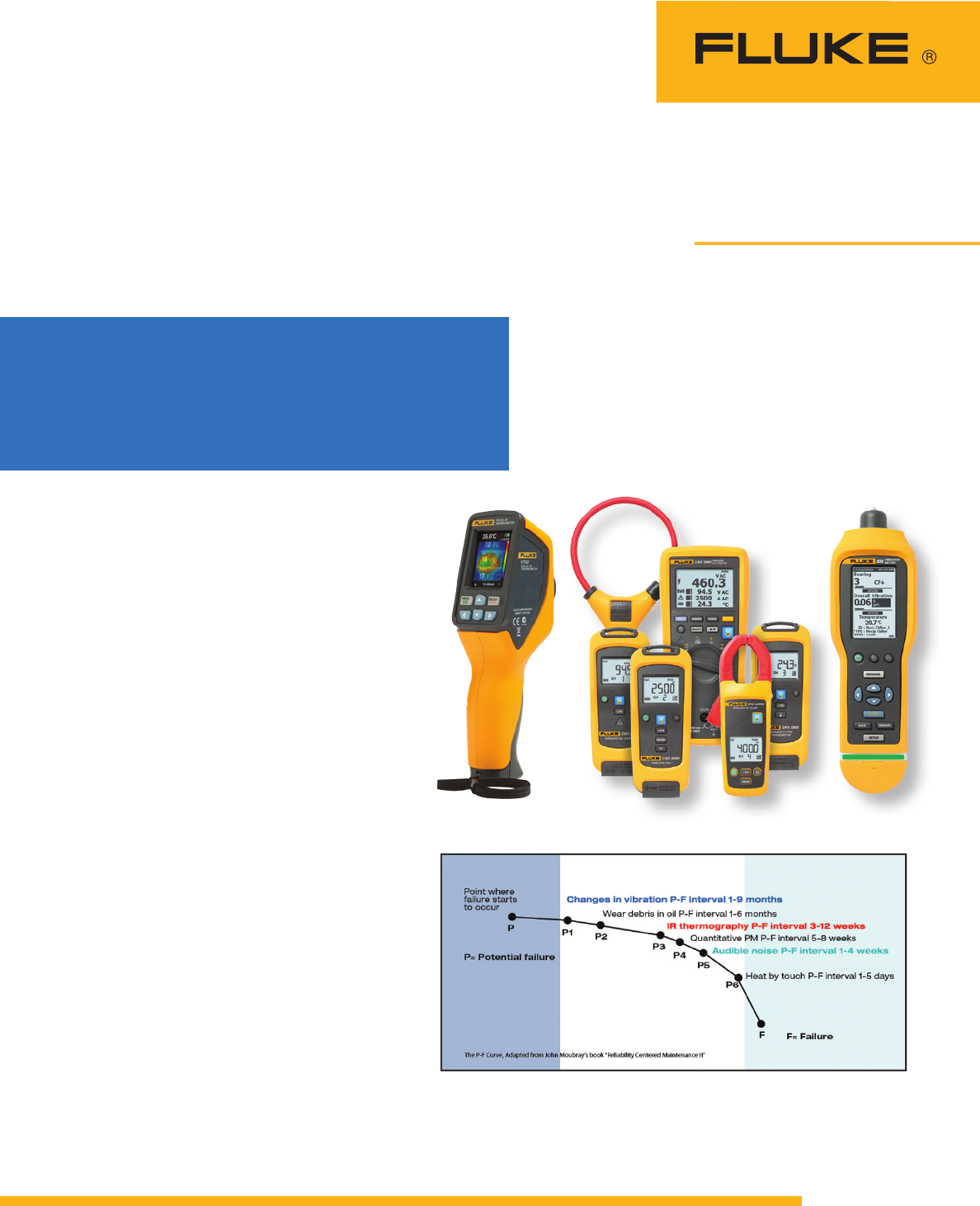
Fluke tools help you detect mechanical problems earlier in the failure curve and prevent
unplanned downtime.
Fluke VT02 Fluke CNX 3000 Wireless System Fluke 805
Visual IR Thermometer Vibration Meter
Unleash your full
troubleshooting powers
with innovative new tools
from Fluke.
2 Fluke Corporation Seven ways to use your troubleshooting superpowers for good
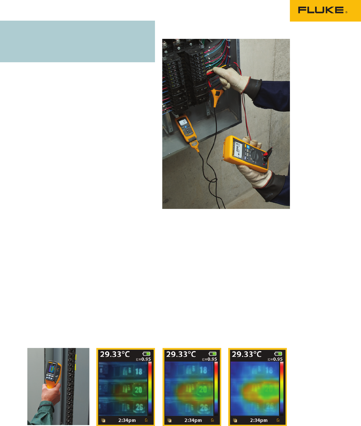
#1 Breaker panel problems
When you’re trying to track down problems in
dirty, wet, or electrically hazardous environments,
Fluke tools help you work more safely and save
you the time of repeatedly suiting up in full per-
sonal protective equipment (PPE).
In this case, you and two other technicians
suit up in full PPE and remove a 90-pound panel
cover that encloses a three-phase breaker panel.
Once it’s open, you scan the panel with the VT02
Visual IR Thermometer. Instead of taking dozens of
measurements with an IR thermometer to check for
issues, the VT02’s blended visual and thermal heat
map image instantly reveals a hot spot on breaker
#20. You capture the image along with the tem-
perature, date and time. Now you know you have
a problem, but you don’t know what’s causing it.
So next, you install a wireless CNX current
clamp to the circuit and re-secure the cover.
With the CNX radio turned on and the log button
pushed, you can now remove your PPE and moni-
tor the circuit from a safe distance, without gearing
up again. You’re free to walk away and do other
jobs while the modules continue to work for you.
Periodically you stop back to check real-time
readings with the CNX DMM, anywhere within
three meters of the panel. If nothing looks abnor-
mal at these spot checks, you can let the module
keep logging. (It can capture up to 65,000 sets
of min/max/avg readings over single or multiple
recording session.)
At the end of the shift you bring your laptop
over to the panel. With the CNX PC adapter plug-
ged into your PC, you wirelessly download the
logged readings directly into the SW3000 software
for analysis. You don’t have to reopen the cabinet
door or suit back up in your PPE.
As you analyze the data, you notice some
unusual surges in the current readings, which
occur intermittently over the day. Using the
time-stamped measurements you can now track
the problem down to a particular process that
switches on at those times. If you have multiple
CNX modules available for troubleshooting you can
monitor multiple points simultaneously and isolate
the problem much faster. But you can also use
single clamp modules and some repetitive testing
to find the source of the problem.
You suspect a motor that’s connected to that
circuit. Scanning that motor with the Fluke 805
reveals a bearing problem. Crest Fact+ technology
allows you to make accurate high-frequency
measurements to diagnose bearings. The four-
level severity scale rates the bearing “unsatisfac-
tory.” You remove it from service and replace the
bearing.
The next day, you recheck the motor with the
Fluke 805. Now it gets a “good” rating. When you
rescan the breaker panel with the VT02, you see
no hot spots on breaker #20 or anywhere else on
the panel. All other temperatures are now within
the normal range.
Here are just a few scenarios
that demonstrate how you can
use your new powers.
You’ll feel like a superhero.
Fluke VT02 25 % blend 50 % blend 75 % blend
Visual IR Thermometer Blended visual and thermal images eliminate guesswork.

3 Fluke Corporation Seven ways to use your troubleshooting superpowers for good
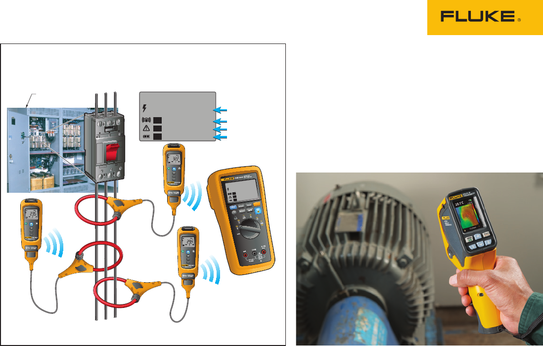
#2 Tracking down motor trouble
During your regular scheduled maintenance check
of critical motors in your plant, you perform a
vibration screening using the Fluke 805 Vibration
Tester. You find a motor that gives an indication of
an internal issue. You connect three wireless CNX
modules and begin monitoring all three phases of
motor current over the course of the week.
While the modules are collecting data, you
make a quick check for hot spots from time to time
with the VT02. Early in the week, you see that the
motor has begun to generate moderate heat at the
drive shaft. By the end of the week, the sides of
the motor appear hot. A quick check with the 805
shows that overall vibration is satisfactory and the
bearings are rated “good” on the severity scale.
Ruling out a mechanical issue, it’s time to search
for an electrical problem.
At the end of the week, you wirelessly down-
load the logged data to the SW3000 software on
your laptop using the Fluke CNX PC Adapter. You
discover from the data that the motor current is
high based on its load. You suspect that this exces-
sive current draw is due to an internal problem in
the motor. It may be time to take the motor offline
and do an insulation resistance test. You can use a
Fluke insulation resistance tester to test the wind-
ing insulation to ground and discover the problem.
You remove the motor from service and replace it
with a different motor while the bad motor is refur-
bished and rewound at a rebuild facility.
#3 Troubleshooting a rooftop
HVAC system
A rooftop air conditioner trips the breaker and
shuts down after only 30 minutes of operation.
Yet at restart, it operates within manufacturer’s
specifications. After it has been running a few
minutes, you check bearings, belts and couplings
for vibration using the Fluke 805. All components
are rated “satisfactory” on the severity scale.
Next you use the VT02 to check around for hot
spots. You check the motor itself to see if the sides
are hot, which would implicate the windings. You
then check the output of the belt the motor is driv-
ing. While you didn’t see vibration on the motor
side with the Fluke 805, the belt may have insu-
lated the motor from a mechanical problem at the
fan. Possibly the fan bearing is damaged, putting
strain on the motor.
You use the VT02 to check motor functions,
driven-device functions (such as the fan bearing)
and the output temperature of the cooled, moving
air. Nothing looks excessive, so it’s time to do some
monitoring.
With the unit continuing to operate, you attach
wireless CNX current modules to the incoming
power legs and a wireless CNX current clamp
module at the load.
Start with an inrush test on motor startup. Use
the “inrush” function on the flex clamps to see if
inrush current to the motor falls within range for
the motor ratings. If the measurement is accept-
able you can then connect multiple current and
voltage modules, letting them log
readings from
startup until the system shuts down.
The wireless modules give you a way to watch
for issues without somebody “living” on the roof.
You can check the live readings from a comfortable
position within 20 meters/60 feet of the modules.
Meanwhile, each module collects time-stamped
measurements, the critical information you’ll need
for a proper diagnosis.
When you download the data later, it reveals
a
large current variance, an increase in amperage,
and an over-heating condition, all with time
stamps. You diagnose a drive component issue.
The repair can be completed after hours. The
system is back up and running quickly, and every-
one keeps cool.

4 Fluke Corporation Seven ways to use your troubleshooting superpowers for good
#4 Finding intermittent faults on a food
processing line
When operating conditions limit access, such as
complex production lines with moving parts and
rotating equipment, innovative Fluke tools can
help you make an assessment without contact.
Maybe there’s an intermittent fault on the line, but
you can’t isolate the problem. With the VT02, you
can stand at a safe distance and quickly scan a
relatively large area. Take a quick survey of the
various motors, drives, and mechanical equip-
ment to look for anything generating heat. When
you find a hot spot on a robotic arm, you capture
a blended visual and thermal heat map image you
can find the exact location of the hot spot along
with a temperature reading.
Now that you’ve narrowed it down, you only
need to access that one particular piece of equip-
ment. You get your opportunity when the line takes
a break. Because of the arm’s movement during
operation, you can’t make measurements with a
standard meter. So you secure CNX current mod-
ules to the arm at suspect power points.When the
line starts up again, you can monitor the readings
from a safe distance using the CNX multimeter.
You watch for a few minutes, but the problem
doesn’t occur while you’re standing nearby, so you
continue on to other jobs and let the CNX module
continue logging the data for you.
A fault occurs late in the shift and the CNX
module has captured a time-stamped event, which
you discover after you wirelessly download the
data to your PC. It’s time to pull out the big guns
and request that a technician perform a full
vibration analysis of the robotic arms using a
Fluke 810 Vibration Meter.
#5 Intermittent motor overload
To troubleshoot an intermittent motor overload
condition—once you’ve ruled out a faulty motor—
start by connecting the CNX wireless voltage
module to the motor starter within the motor con-
trol center and the CNX wireless current module to
the field disconnect switch adjacent to the motor.
Then, while the motor is operating,
verify and
view the supply voltage and current
with the CNX
multimeter, while checking temperature with the
VT02, to help you narrow down the variables. If
the supply voltage drops, the power company has
a problem that’s overworking the motor. If cur-
rent draw is excessive, there may be a mechanical
problem with the motor, which you can quickly
check out with the Fluke 805 to detect overall
vibration or to find a faulty bearing. The VT02 will
help you identify any areas generating excess
heat. If there’s heat, but you’re not detecting vibra-
tion, perhaps the problem is from the load the
motor drives. Check to see if vibration in the load
is causing the motor to work too hard.
If you can’t identify the problem on the spot, just
leave the modules in place to log data. Later you
can download it for full review and evaluation to
isolate the source of the problem.
5 Fluke Corporation Seven ways to use your troubleshooting superpowers for good
#6 Diagnosing a three-phase motor
without suiting up
If you have a big motor you need to diagnose, such
as a 408 V AC 200 HP motor with a wye-delta, you
can use the CNX wireless system to test without
needing personal protective equipment (PPE). Dis-
connect power before you open the motor control
center (MCC) cabinet. Then connect three hard jaw
clamp CNX current modules—one per phase—to
measure three-phase current. Or, connect three
CNX voltage modules or use a combination of both.
Close the MCC cabinet, re-apply power and start
the motor. Now you can take all the measure-
ments without PPE. These tests will show you if
the motor is working too hard electrically. If it is,
you still need to find out why. The 805 will show
you mechanical problems. The VT02 will reveal
hot spots. Heat with no vibration could help verify
internal electrical faults.
#7 Pump occasionally blows a fuse
You have a pump motor that occasionally blows a
fuse, and you can’t find an obvious cause. Set up
a CNX current module, securing it to an electrica
l
disconnect and feeding the module wires through
a ½ inch knockout. Now you can monitor the amps
wirelessly and discover what’s causing the fuse
to blow—or at least you’ll know the timing of the
event. By the next morning, you’ll know the exact
time when the event occurs.
You may find that at the time of the fault,
multiple processes start up, creating an excessive
load on a branch circuit, causing a nuisance trip.
Resizing the breaker or redistributing the loads
may solve this type of problem. It could also be
a loose connection. The VT02 is helpful for finding
those. Check for hot spots that signal loose con-
nections in the circuit, possibly at one of the loads.
Fluke. Keeping your world
up and running.®
Fluke Corporation
PO Box 9090, Everett, WA 98206 U.S.A.
Fluke Europe B.V.
PO Box 1186, 5602 BD
Eindhoven, The Netherlands
For more information call:
In the U.S.A. (800) 443-5853 or
Fax (425) 446-5116
In Europe/M-East/Africa +31 (0) 40 2675 200 or
Fax +31 (0) 40 2675 222
In Canada (800)-36-FLUKE or
Fax (905) 890-6866
From other countries +1 (425) 446-5500 or
Fax +1 (425) 446-5116
Web access: http://www.fluke.com
©2013 Fluke Corporation.
Specifications subject to change without notice.
Printed in U.S.A. 03/2013 4331701A A-EN
Modification of this document is not permitted
without written permission from Fluke Corporation.
0.0
32.2
23.5
29.4
V AC
A AC
A AC
A AC
Auto
1
2
3
INRUSH
Hz
L1 L2 L3
L1
DMM
L2
L3
Motor power
Cabinet
INRUSH
Hz
INRUSH
Hz
INRUSH
Hz
0.0
32.2
23.5
29.4
V AC
A AC
A AC
A AC
Auto
1
2
3
Determining current unbalance
