Flyingvoice Network Technology FTA1101 VoIP Wireless ATA User Manual user manual
Flyingvoice Network Technology Co., Ltd VoIP Wireless ATA user manual
User manual

User Manual
User Manual
FTA1101
Version 1.0

User Manual
Revision Record
Version Date Description Applicability
V1.0 2017-3-7 The first edition

User Manual
Table of Contents
1. Introduction...................................................................................................................................1
1.1 Package Contents ................................................................................................................1
2. Product Overview .........................................................................................................................2
2.1 FTA1101 .............................................................................................................................2
2.2 Hardware Specification....................................................................................................... 2
2.3 Front View and LEDs Introduction.....................................................................................3
Installation.........................................................................................................................................5
2.4 Connection topography .......................................................................................................5
2.5 Installation Steps ................................................................................................................. 5
3. IVR................................................................................................................................................ 6
3.1 Ways to Configuration ........................................................................................................6
3.2 Start IVR .............................................................................................................................6
3.3 IVR Description ..................................................................................................................6
3.4 Notice..................................................................................................................................9
4. Parameters Introduction ..............................................................................................................10
4.1 Password ...........................................................................................................................10
4.2 URL format .......................................................................................................................10
5. Login to WEB ............................................................................................................................. 11
5.1 Login WEB via LAN port................................................................................................. 11
5.2 Login WEB via WAN port ................................................................................................ 11
5.3 WEB Interface Introduction..............................................................................................12
6. Configuration from WEB............................................................................................................13
6.1 Status.................................................................................................................................13
6.1.1 Basic....................................................................................................................... 13
6.1.2 Syslog..................................................................................................................... 14
6.2 Network............................................................................................................................. 15
6.2.1 WAN.......................................................................................................................15
6.2.2 LAN .......................................................................................................................16
6.2.3 VPN Settings..........................................................................................................18
6.2.4 DMZ.......................................................................................................................18
6.2.5 DDNS..................................................................................................................... 18
6.2.6 Port Setting.............................................................................................................18
6.3 Wireless.............................................................................................................................20
6.3.1 Basic....................................................................................................................... 20
6.3.2 Wireless Security....................................................................................................21
6.3.3 WMM.....................................................................................................................21
6.3.4 WPS .......................................................................................................................21
6.3.5 Station Info............................................................................................................. 22
6.3.6 Advanced................................................................................................................22
6.4 SIP.....................................................................................................................................23

User Manual
6.4.1 Line1 ......................................................................................................................23
6.4.2 SIP Settings ............................................................................................................26
6.4.3 VoIP QoS................................................................................................................ 26
6.5 Phone................................................................................................................................. 27
6.5.1 Preferences .............................................................................................................27
6.5.2 Dial Rule ................................................................................................................ 28
6.5.3 Phonebook..............................................................................................................28
6.5.4 Call Log..................................................................................................................30
6.6 Administration...................................................................................................................30
6.6.1 Management...........................................................................................................30
6.6.2 Firmware Upgrade ................................................................................................. 32
6.6.3 Certificates .............................................................................................................32
6.6.4 Provisioning ...........................................................................................................33
6.6.5 SNMP..................................................................................................................... 34
6.6.6 TR069.....................................................................................................................34
6.6.7 Diagnosis................................................................................................................36
7. Functions.....................................................................................................................................36
7.1 Making Calls.....................................................................................................................36
7.2 Call Waiting ......................................................................................................................36
7.3 Call Hold...........................................................................................................................36
7.4 Call Transferring...............................................................................................................37
7.4.1 Blind Transfer ........................................................................................................37
7.4.2 Attended Transfer...................................................................................................37
7.5 3-way conference call .......................................................................................................37
7.6 Call Forwarding ................................................................................................................37
7.7 Direct IP calls.................................................................................................................... 38
7.8 Speed dialing.....................................................................................................................38
7.9 Hotline............................................................................................................................... 39
7.10 Daylight Saving Time .....................................................................................................39
7.11 Upgrade Firmware...........................................................................................................39
7.12 Password Control ............................................................................................................40
7.13 Web Access .....................................................................................................................40
7.14 System log....................................................................................................................... 40
8. Software Feature .........................................................................................................................41

User Manual
1
1. Introduction
Thank you for choosing FTA1101 Wireless VoIP ATA adapter. This ATA adapter will allow user to
make ATA call using your broadband connection.
This manual provides basic information on how to install and connect FTA1101 VoIP ATA adapter
to the Internet. It also includes features and functions of FTA1101 VoIP ATA adapter components,
and how to use it correctly.
Before you can connect FTA1101 to the Internet and use it, you must have a high-speed
broadband connection installed. A high-speed connection includes environments such as DSL,
cable modem, and a leased line.
FTA1101 VoIP ATA adapter is a stand-alone device, which requires no PC to make Internet calls.
This ATA adapter guarantees clear and reliable voice quality on Internet, which is fully compatible
with SIP industry standard and able to interoperate with many other SIP devices and software on
the market.
1.1 Package Contents
User package includes:
One FTA1101 VoIP ATA Adapter
One Ethernet cable
Two telephone lines
If the above device or accessory is damaged or lost, please contact with your reseller for
replacement.
User Manual
2
2. Product Overview
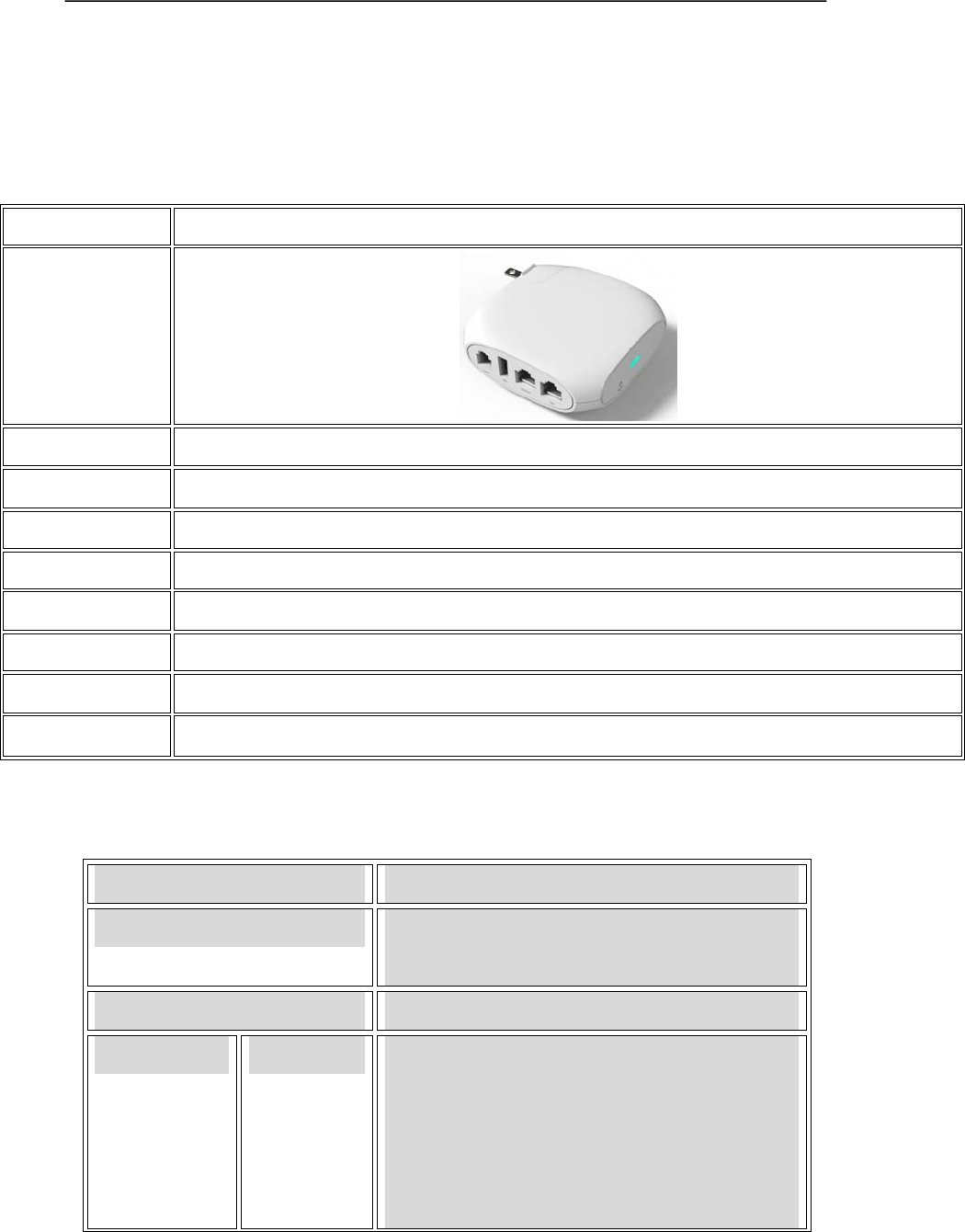
2.1 FTA1101
Features/Model FTA1101
Picture
Network Ports 2 RJ45 10/100Mbps (WAN/LAN)
FXS Ports 1
SIP Accounts 1
LTE 1
DHCP Client/Server
Voice Codec G.711(A-law, U-law), G.729A/AB,G.723,G.722
Management Integrated IVR, Web browser, Auto-Provision with HTTP/TFTP/HTTPS,TR069, SNMP
FAX T.30,T.38 Fax
2.2 Hardware Specification
Item specification
Power Adapter AC/DC Adapter,
AC Input: 100~240V, 50~60Hz
CPU MT7628
Port WAN 1 RJ-45 for WAN port (Ethernet 100 Base-T)
1 RJ-45 for LAN port (Ethernet 100 Base-T)
1 RJ-11 for FXS port
1 USB
IEEE802.11 b/g/n
User Manual
3
Operating Temperature -5~45℃(41~113℉)
Storage Temperature -25~85℃(-13~185℉)
Relative Humidity 10~90% (No condensing)
Dimension (L×W×H) 85×85×28mm
Weight (packaging included) 366g
Certification CE / FCC / RoHS
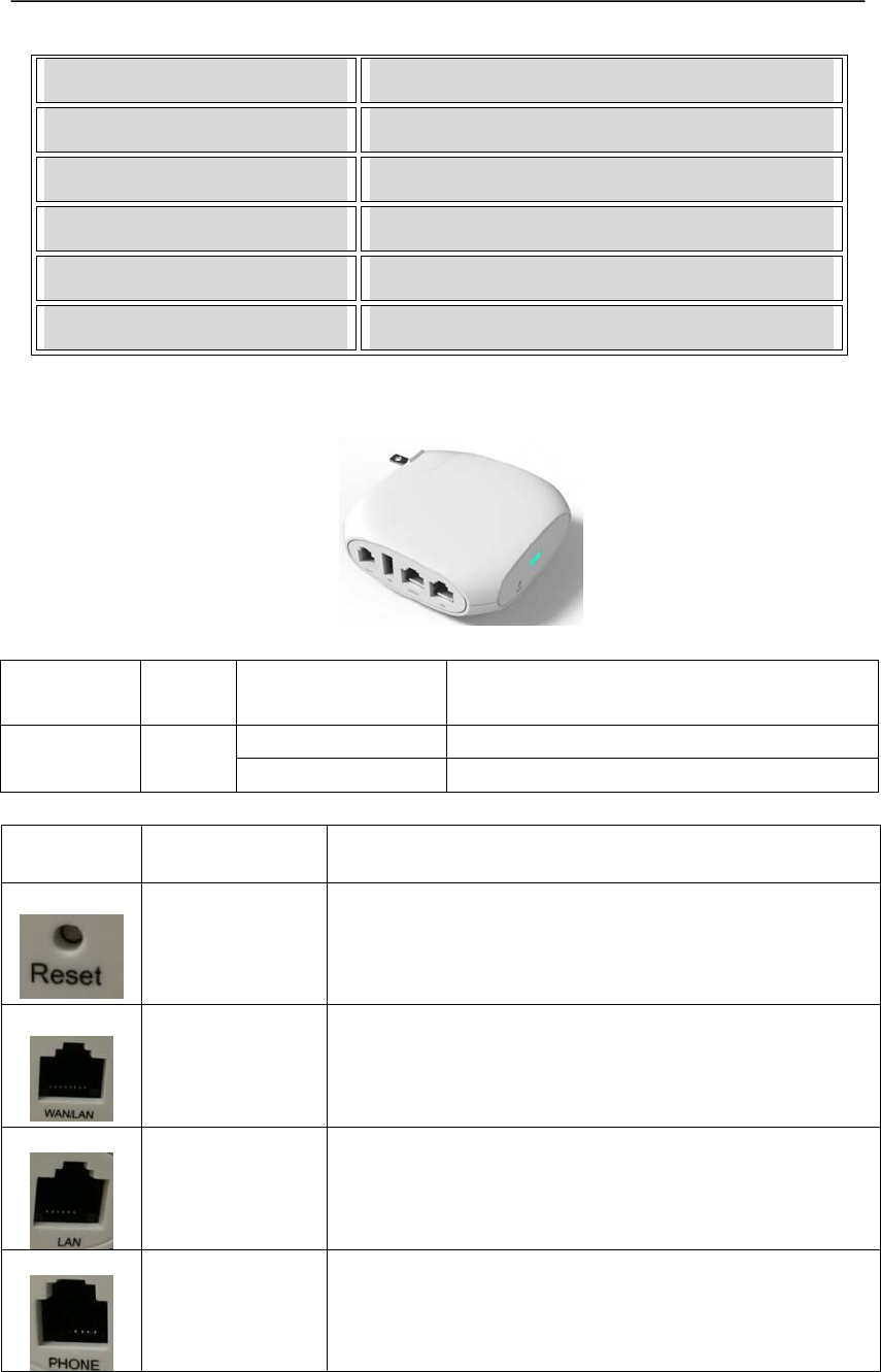
2.3 Front View and LEDs Introduction
Front View
LED
Indicator Color Status Description
Solid The device network is working normally
Power Red Blinking The device is power on
Port Name Description
Reset Press 10s to set FTA1101 factory settings.
WAN(RJ-45) Connect to Internet or router
LAN(RJ-45) Connect to PC or build a small LAN network
PHONE(RJ11) Connect to traditional phone or FAX Machine

User Manual
4
USB For phone charger or LTE Dongle
User Manual
5
Installation
This chapter introduces how to install FTA1101..
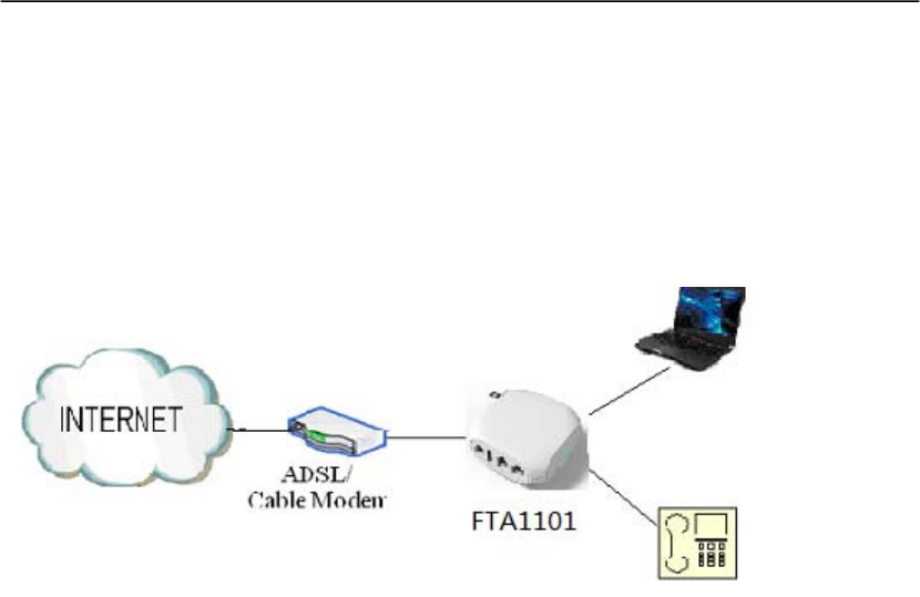
2.4 Connection topography
2.5 Installation Steps
Step 1: Insert one end of the Ethernet cable into the WAN port on the back panel of the FTA1101
and the other end of cable to your existing broadband connection port (e.g. router or
Ethernet switch)
Step 2: Connect the LAN port on the back panel of the FTA1101 to your conventional ATA using
a standard ATA cabling
Step 3: If need to set up a small LAN network, the FTA1101 should work in router or bridge mode
so that you or more people can access to the Internet through FTA1101. Then you need to
connect your PC or LAN connection equipment (e.g. Ethernet switch) to the LAN port on
the back panel of the FTA1101 using Ethernet cable. (Step 3 is optional depending on your
needs)
Step 4: Connect the power adapter to the power port at the back panel of FTA1101 and then plug
another end of power adapter into a wall outlet or power strip. The LED of FTA1101 will
turn on to indicate operated properly.
Warning: Please do not attempt to use other different power adapter or cut off power supply
during configuration or updating FTA1101 VoIP ATA adapter. Using other power adapter
may damage FTA1101 VoIP ATA adapter and will void the manufacturer warranty.
User Manual
6
3. IVR
3.1 Ways to Configuration
FTA1101 support three ways to configuration.
Use IVR.
Use web browser(recommend way)
Use provision.
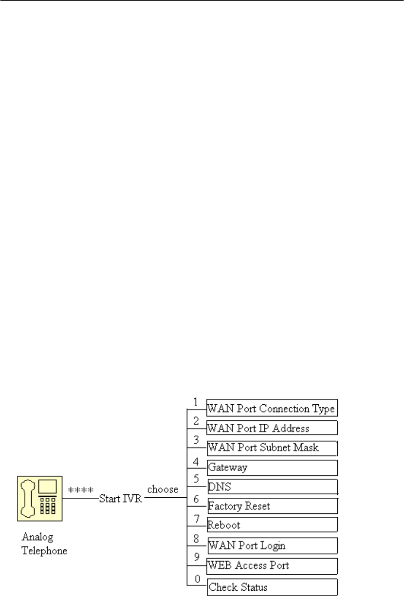
3.2 Start IVR
Customer can use the IVR function by referring to the following steps:
Step 1.Connect analog phone to FTA1101’s phone port
Step 2.Pick up phone and press “****” to start IVR, then FTA1101 will report sound prompting
“please enter your option, one WAN Port ……”.
Step 3.Choose the operation code from 0 to 9, then FTA1101 will report the contents, details are
in the following table.
Step 4.Every time after successfully operation, FTA1101 will return to sound prompting “please
enter your option, one WAN Port ……”.
3.3 IVR Description
Below is the table that lists command, and description.

User Manual
7
Operation code Contents
1
Step 1.Pick up phone and press “****” to start IVR
Step 2.Choose “1”, and FTA1101 report the current WAN port
connection type
Step 3.Prompt "Please enter password”, user need to input password
with end char # if user want to configuration WAN port
connection type.
The password in IVR is same as the one of WEB login, user can use
phone keypad to enter password directly, and the matching table is
in Note 4.
For example: WEB login password is “admin”, so password in IVR
is “admin” too, user input “23646” to access and then configuration
WAN connection port.
Step 4.Report “operation successful” if password is right.
Step 5.Choose the new WAN port connection type from 1.DHCP and
2.Static
Step 6.Report “operation successful”, this means user make the changes
successfully, and then FTA1101 will return to sound prompting
“please enter your option, one WAN Port ……”.
Note: add “#” to assume after input password and selected new
WAN port connection type
If you want to quit by the wayside, press “*”
2
Step 1.Pick up phone and press “****” to start IVR
Step 2.Choose “2”, and FTA1101 report current WAN Port IP Address
Step 3.Input the new WAN port IP address and with the end char #,
using “*” to replace “.”, user can input 192*168*20*168 to set the
new IP address 192.168.20.168
press # key to indicate that you have finished
Step 4.Report “operation successful” if user operation properly.
Note: If you want to quit by the wayside, press “**”.
3
Step 1.Pick up phone and press “****” to start IVR
Step 2.Choose “3”, and FTA1101 report current WAN port subnet mask
Step 3.Input a new WAN port subnet mask and with the end char #
using “*” to replace “.”, user can input 255*255*255*0 to set the
new WAN port subnet mask 255.255.255.0
press # key to indicate that you have finished
3) Report “operation successful” if user operation properly.
Note: If you want to quit by the wayside, press “**”.
4
Step 1.Pick up phone and press “****” to start IVR
Step 2.Choose “4”, and FTA1101 report current gateway
Step 3.Input the new gateway and with the end char #
using “*” to replace “.”, user can input 192*168*20*1 to set the

User Manual
8
new gateway 192.168.20.1
press # (pound) key to indicate that you have finished
3) Report “operation successful” if user operation properly.
Note: If you want to quit by the wayside, press “**”.
5
Step 1.Pick up phone and press “****” to start IVR
Step 2.Choose “5”, and FTA1101 report current DNS
Step 3.Input the new DNS and with the end char #
using “*” to replace “.”, user can input 192*168*20*1 to set the
new gateway 192.168.20.1
press # (pound) key to indicate that you have finished
3) Report “operation successful” if user operation properly.
If you want to quit by the wayside, press “**”.
6
Step 1.Pick up phone and press “****” to start IVR
Step 2.Choose “6”, and FTA1101 report “Factory Reset”
Step 3.Prompt "Please enter password", the method of inputting
password is the same as operation 1.
If you want to quit by the wayside, press “*”.
Step 4.Prompt “operation successful” if password is right and then
FTA1101 will be factory setting.
Step 5.Press “7” reboot to make changes effective.
7
Step 1.Pick up phone and press “****” to start IVR
Step 2.Choose “7”, and FTA1101 report “Reboot”
Step 3.Prompt "Please enter password", the method of inputting
password is same as operation 1.
Step 4.FTA1101 will reboot if password is right and operation is
properly.
8
Step 1.Pick up phone and press “****” to start IVR
Step 2.Choose “8”, and FTA1101 report “WAN Port Login”
Step 3.Prompt "Please enter password", the method of inputting
password is same as operation 1.
If you want to quit by the wayside, press “*”.
Step 4.Report “operation successful” if user operation properly.
Step 5.Prompt “1enable 2disable”,choose 1 or 2, and with confirm char
#.
Step 6.Report “operation successful” if user operation properly.
9
Step 1.Pick up phone and press “****” to start IVR
Step 2.Choose “9”, and FTA1101 report “ WEB Access Port”
Step 3.Prompt “Please enter password”, the method of inputting
password is same as operation 1.
Step 4.Report “operation successful” if user operation properly.
Step 5.Report the current WEB Access Port
Step 6.Set the new WEB access port and with end char #

User Manual
9
3.4 Notice
In Voice Menu, press *(star) to return to up level menu.
If any changes made in the IP assignment mode, please reboot the FTA1101 to take the
settings into effect.
When enter IP address or subnet mask, input “*” after an address field and add “#” to finish
inputting
For example, to enter the IP address 192.168.1.11 by keypad, press these keys:
192*168*1*11#.
You can enter the password by phone keypad, the matching table between number and letters
as follows:
To input: A, B, C, a, b, c -- press ‘2’
To input: D, E, F, d, e, f -- press ‘3’
To input: G, H, I, g, h, i -- press ‘4’
To input: J, K, L, j, k, l -- press ‘5’
To input: M, N, O, m, n, o -- press ‘6’
To input: P, Q, R, S, p, q, r, s -- press ‘7’
To input: T, U, V, t, u, v -- press ‘8’
To input: W, X, Y, Z, w, x, y, z -- press ‘9’
To input all other characters in the administrator password-----press ‘0’,
E.g. password is ‘admin-admin’, press ‘23646023646’.
Press # (pound) key to indicate that you have finished entering the IP address or subnet mask
or other settings.
When assigning IP address in Static IP mode, customer must set IP address, subnet mask and
default gateway. If in DHCP mode, please make sure that DHCP Server is available in your
existing broadband connection to which WAN port of FTA1101 is connected.
Step 7. Report “operation successful” if user operation properly.
0 Step 1.Pick up phone and press “****” to start IVR
Step 2.Choose “0”, and FTA1101 report current Firmware version

User Manual
10
4. Parameters Introduction
4.1 Password
There are 2-level to access to FTA1101: administrator level and user level, password of
different levels are different.
User with administrator level can browse and set all configuration parameters, while user
with user level can set all configuration parameters except SIP1/2 that some parameters can
not be changed, such as server address and port. User has different access level with different
password.
Default user with administrator level:
Username:admin, Password:admin
Default user with user level
Username:admin, Password: user
4.2 URL format
The WEB login URL format is http://xxx.xxx.xxx.xxx. xxx.xxx.xxx.xxx stands for the IP address
of LAN or WAN port.
Below are two examples about the URL of LAN port and WAN port.
LAN port:
Default URL of LAN port is: http://192.168.1.1
Note: 192.168.1.1 is FTA1101 default LAN port’s IP address
WAN port:
Get WAN port address from IVR function or in Status/Basic webpage
(Assuming the IP is: 192.168.100.18)
The URL: http://192.168.100.18
User Manual
11
5. Login to WEB
FTA1101 has an embedded Web server that will respond to HTTP get/post requests.User can use
a Web browser like Microsoft’s IE to login and then configure FTA1101.
5.1 Login WEB via LAN port
Step 1: Open WEB browser;
Step 2: Input the LAN port URL, default is http://192.168.1.1;
Note:
User PC has the IP Address which is in the same segment of LAN port IP address,
otherwise you can not open the login page successfully.
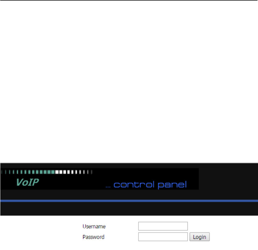
Step 3: Once the right http request is entered and sent by the Web browse,the ATA will respond
with the following login page.
Step 4: Input the password
Note: The password is case sensitive.
Step 5: First page user will see is Status page.
5.2 Login WEB via WAN port
Step 1: Open WEB browser;
Step 2: Lookup WAN port IP Address from IVR function or from WEB;
Step 3: Input the WAN port URL
User’s PC should have the IP Address which is in the same segment of WAN port IP
address, otherwise you can not open the login page successfully.
Step 4: Once the right http request is entered and sent by the Web browse,the ATA will respond
with login page.
Step 5: Input the password
Note: The password is case sensitive.
User Manual
12
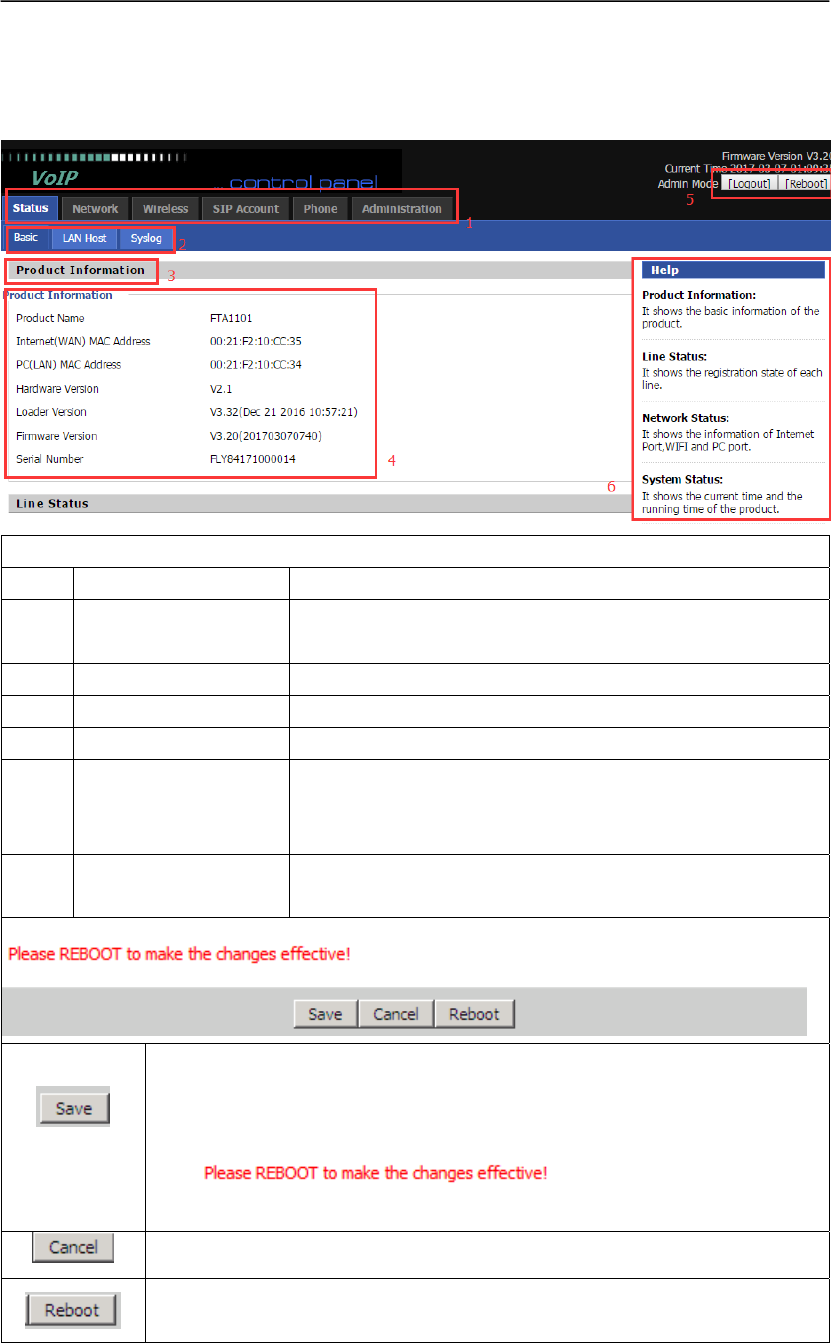
5.3 WEB Interface Introduction
Name Description
1 navigation bar Click navigation bar, many sub-navigation bar will appear in
the place 2
2 sub-navigation bar Click sub-navigation bar to enter to configuration page
3 configuration title The configuration title
4 configuration bars The configuration bars
5
main information Display the firmware version, DSP version, Current Time,
and user can change login level (mode) to return to login
page by press blue Switch button.
6 Help Display the main information for configuration; user can get
help from it directly.
Every time making some changes, user should press the button to confirm the
changes.
After pressing the button, the red notice
will appear to notice user to reboot.
To cancel the changes.
Press it to reboot FTA1101.
User Manual
13
6. Configuration from WEB
6.1 Status
User can view FTA1101 Basic and Syslog. It is the first page which user will see firstly after login
to WEB.
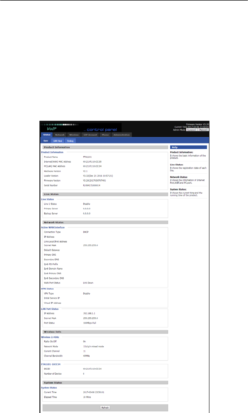
6.1.1 Basic
User can see the Product Information, SIP Account Status, Net Status, VPN Status, LAN Status,
and System Status.
User Manual
14
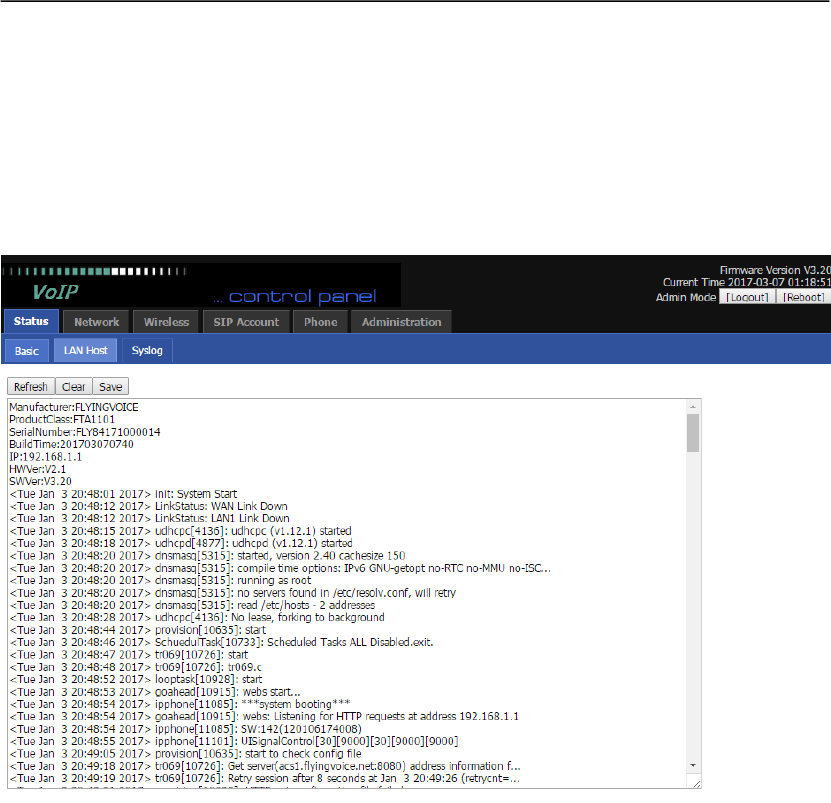
6.1.2 Syslog
In this configuration Interface,you can view Syslog, which record the FTA1101’s important
configuration information.
By default, syslog is enabled, and the level is INFO, there are two system log level, INFO and
Debug, in Debug level, there will be more information. If you want to change, please go to
Administration/Management page, System Log Setting column to change.
Click Refresh to refresh the system log, and click Clear to empty the current system log and click
Save to save the system log to your local PC.
User Manual
15
6.2 Network
6.2.1 WAN
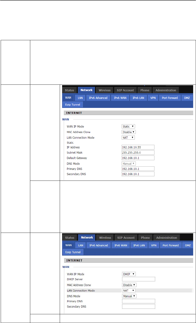
Introduction
The Internet Setup is to set WAN port mode, IP address and so on.
User can choose one WAN mode from Static, DHCP and PPPoE
Static: Users need to set IP Address, Subnet Mask, Gateway IP and DNS.
DHCP: FTA1101 will auto-configuration the WAN parameter with immediate
effect.
PPPoE: Users can enable FTA1101 to connect to Internet by ADSL.
WEB
Interface
1.Static
Settings
Introduction
1) Set “Static” in the “INTERNET” text.
2) Set IP address, the IP address is the one of the local area
network.
3) Set Subnet Mask, it is usually “255.255.255.0” for the local
area network.
4) Set Gateway, you can get it from your Administrator.
5) Set DNS, you can get it from your Administrator.
WEB
Interface
2.DHCP
1) Set “DHCP” in the “INTERNET” text.
User Manual
16
Settings
Introduction
2) DNS type: Manual and Auto
In Manual: user should set the Primary DNS and Second
DNS manually.
In Auto: FTA1101 will get the Primary DNS and Second
DNS from DHCP Server automatically.
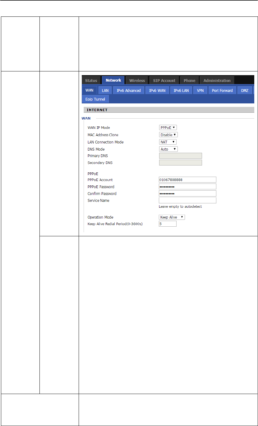
WEB
Interface
3.PPPoE
Settings
Introduction
1) Set “PPPoE” in the “INTERNET” text
2) Fill the PPPoE account and password in the texts.
3) You should set “manual” in the “DNS Mode” if you set “DNS”
by yourself. And then fill the DNS in the two following texts.
Generally speaking, you can set “Auto” in the “DNS Mode” and
FTA1101 will get “DNS” from DHCP Server automatically.
4) You should click the “Reboot” in the left of the page to reboot
the FTA1101 if you see the words “Please REBOOT to make the
changes effective!” After Reboot, you can see PPPoE Status and
the network parameters in the System Status page if FTA1101
connect successfully.
You can select the “PPPoE” IP Mode if you are family users or
your PC connects to Internet by ADSL. You should connect your
PC with FTA1101’s LAN. In detail, you can see the following
LAN settings.
Port Bind
WAN connection can not be shared between the binding port ,
and finally bound port WAN connections bind operation will
wash away before the other WAN connection to the port binding
User Manual
17
operation! When you set several different vlans for WAN port,
user can use this option to define the LAN port’s service, usually
please bind Internet VLAN to LAN port.
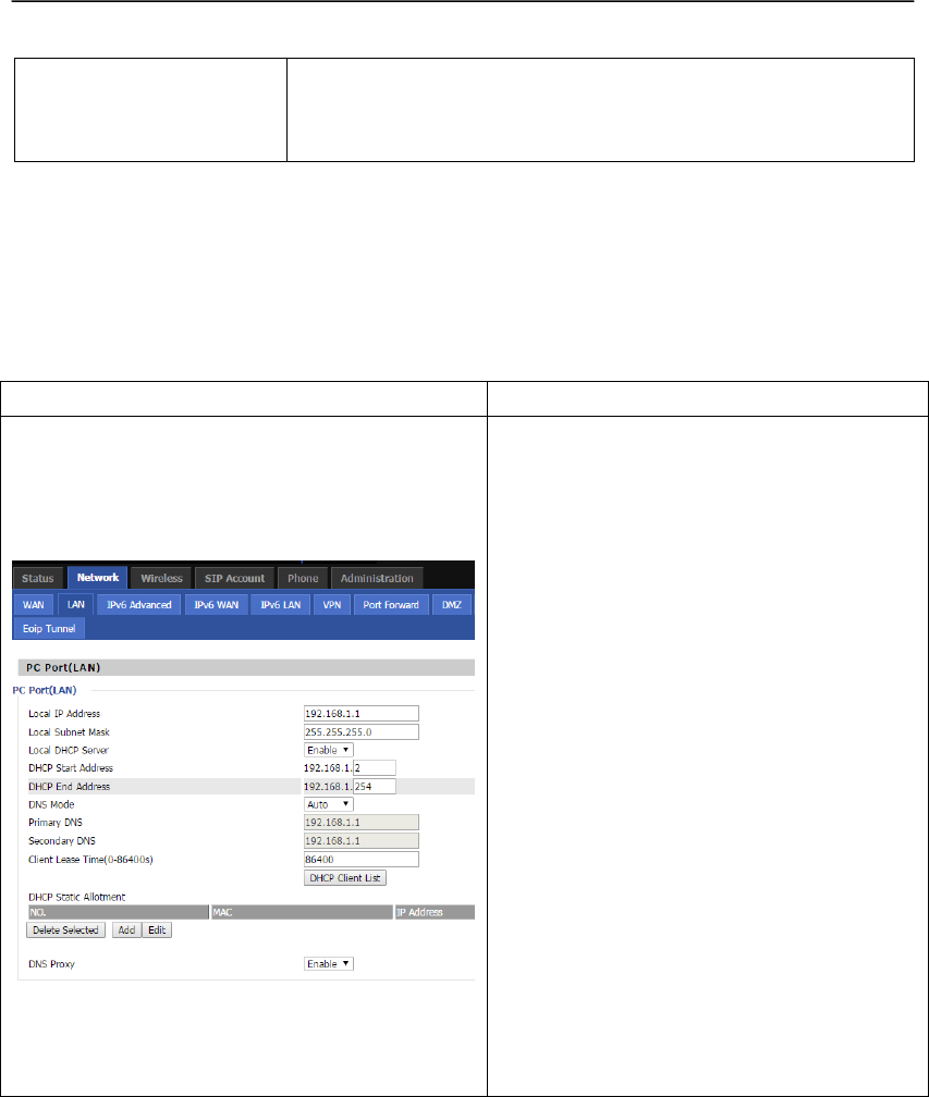
6.2.2 LAN
In this page, user can set the IP address of the device and set DHCP server. DHCP server is a kind
of network function, FTA1101 can supply DHCP service for the network which is linked with
FTA1101’s LAN if you enable the DHCP server for FTA1101’s LAN.(By default this is enabled).
WEB Interface Settings Introduction
1) Local IP Address and Local Subnet Mask
Set the LAN port IP address and subnet
mask. By default the address is 192.168.1.1
and subnet mask is 255.255.255.0.
2) Local DHCP Server and DHCP Start/End
Address
If or not enable the DHCP service, and set
the start and end address of the DHCP server.
By default DHCP server is enabled.
3) DNS Mode and Primary/Secondary DNS
Set the DNS mode and address for the DHCP
server. If set Auto, the device will get the
address from the upstream route, if set
Manual, user need enter the primary and
secondary DNS.
4) Client Lease Time
Set client lease time.
5) DNS Proxy
If or not enable DNS proxy.
User can use the default settings.
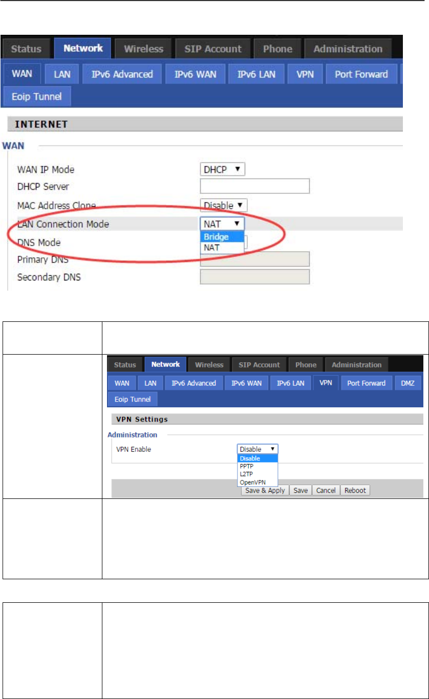
By default, the LAN port works in NAT mode, if user wants to make it work in Bridge mode,
please go to Network-->WAN page to set.
User Manual
18
6.2.3 VPN Settings
Generally
Introduction
FTA1101 has two kinds VPN: PPTP and L2TP.
WEB
Interface
Settings
Introduction
1)VPN Enable: If or not enable VPN, user can select from PPTP and
L2TP.
2)Initial Service IP:VPN server IP address
3)User Name: the user name for authentication
4)Password: password for authentication
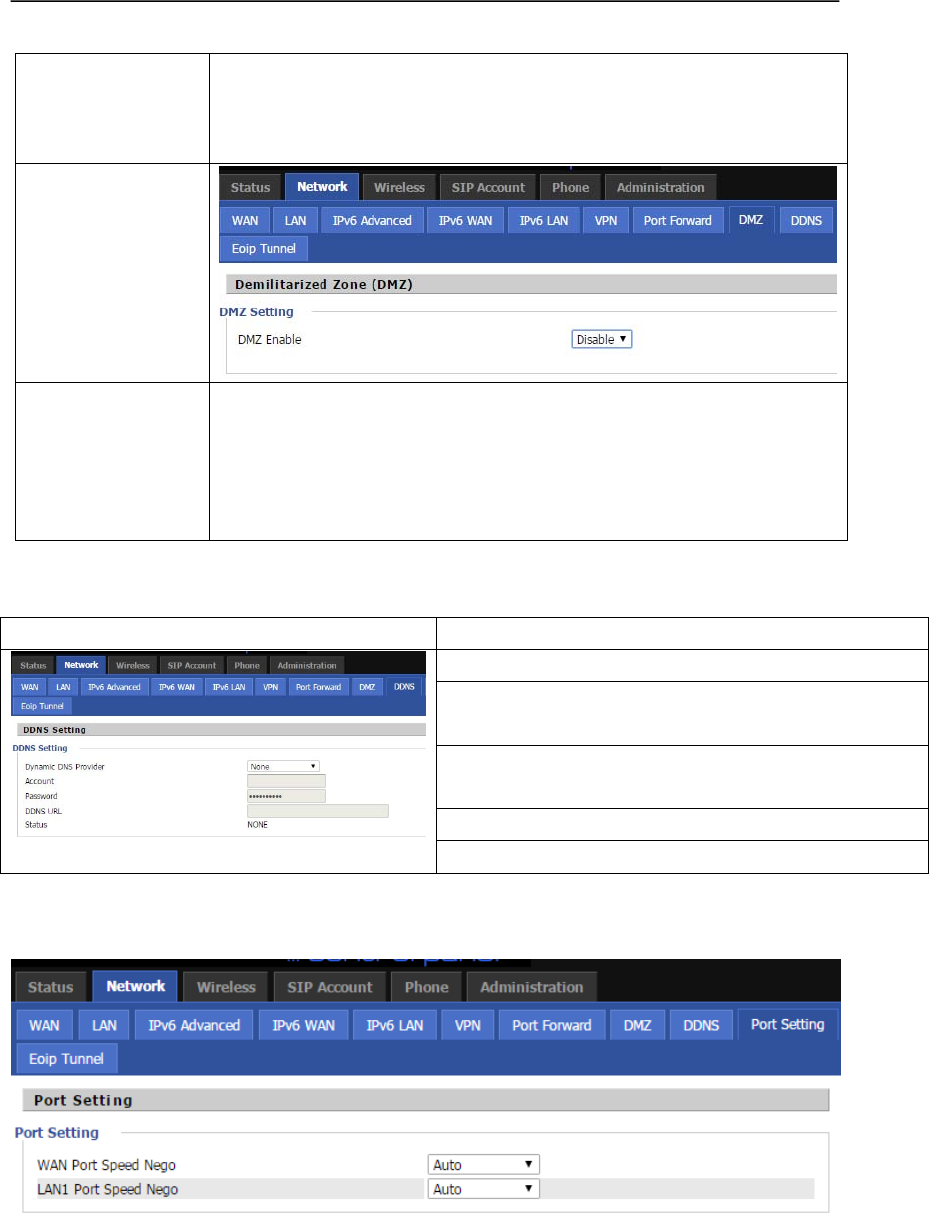
6.2.4 DMZ
Generally
Introduction
FTA1101 will forbid the outside requests if you enable the NAT.
However, sometimes it is needed to access the PC which is linked
with FTA1101’s LAN to use the PC’s service. Now, you should use
the FTA1101’s DMZ to realize it.
Here, DMZ is the same with mapping ports for network equipment.
PC which is linked with FTA1101’s LAN can get the requests from
User Manual
19
the LAN by some ports of FTA1101’s WAN retransmits. (Your PC
is DMZ computer for short as follows.)
User must enable “NAT” mode when want to use DMZ.
WEB
Interface
Settings
Introduction
1)DMZ Enable: if or not enable DMZ
2)DMZ Host IP Address: set the IP address of DMZ host
For example, the DMZ computer’s IP is “192.168.1.2”, the DMZ
function is that DMZ computer can get the requests from the ports of
FTA1101’s WAN port.
6.2.5 DDNS
Webpage Description
Dynamic DNS provider: Select the DDNS provider.
Account: Enter the account user gets from the DDNS
provider.
Password: Enter the password user gers from the
DDNS provider.
DDNS: Enter the DDNS domain.
Status:Display the DDNS connection status.
6.2.6 Port Setting
In this webpage, user can set WAN/LAN port speed negotiation, default are Auto, and options are
100Mbps Full, 100Mpbs Half,10Mbps Full and 10Mbps Half.
User Manual
20
6.3 Wireless
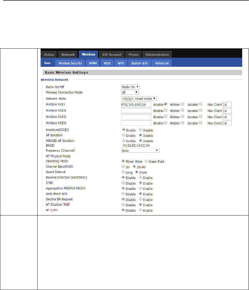
6.3.1 Basic
WEB
Interface
Settings
Introduction
1) Radio On/Off: Select Radio On to enable the wireless, select Radio Off to
disable wireless.
2) Network Moder: Choose one network mode from the five types.
3) SSID: The name of the wireless name, it can be any text numbers or various
special characters. The default SSID is "VWRT510131028".
4) Multiple SSID1-3: User can set multiple SSID.
5) broadcast(SSID): If or not enable SSID broadcast.
User Manual
21
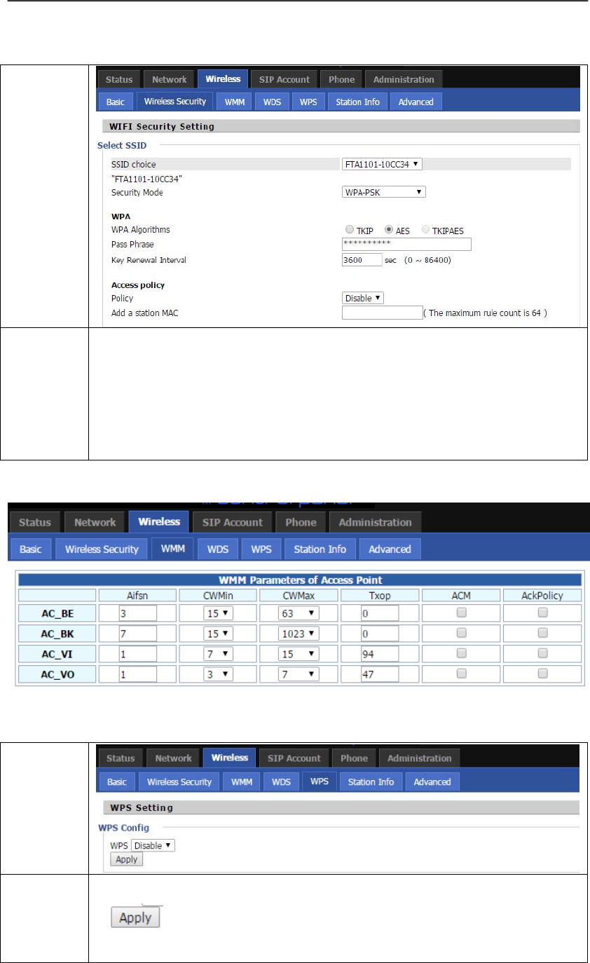
6.3.2 Wireless Security
WEB
Interface
Settings
Introduction
1)SSID Choice: Choose one SSID from SSID, Multiple SSID1, Multiple SSID2
and Multiple SSID3.
2) Security Mode: Select an appropriate encryption mode to improve
the security and privacy of your wireless data packets. Each encryption mode will
bring out different web page and ask you to offer additional configuration.
6.3.3 WMM
6.3.4 WPS
WEB
Interface
Settings
Introduction
1)WPS: If or not enable WPS.
2) Press the button to apply.
User Manual
22
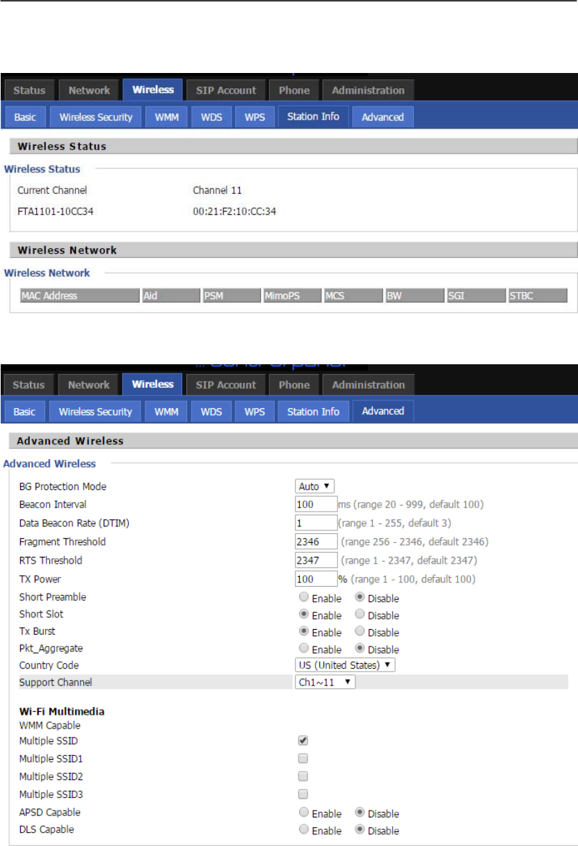
6.3.5 Station Info
6.3.6 Advanced
User Manual
23
6.4 SIP
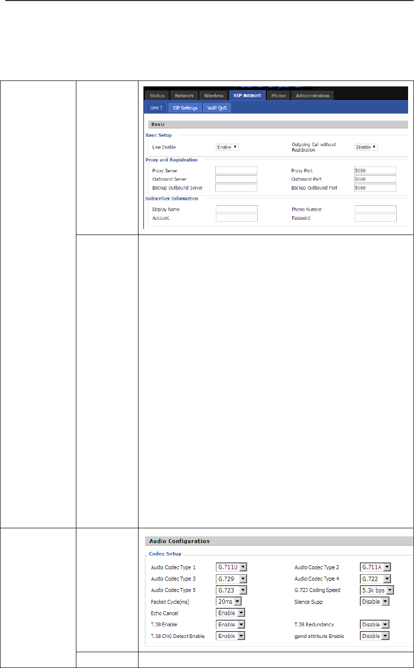
6.4.1 Line1
WEB
Interface
Basic
Settings
Introduction
1) Line Enable: If or not enable FXS1
2) Peer To Peer: If or not enable Peer To Peer on FXS1 port.
3) SIP Proxy: The IP address of SIP Server.
4) SIP Proxy Port: The port which SIP Server supports for
VOIP service, default is 5060.
You should enable “Carry Port Information” in the Other
Settings page if the SIP Server Port is not 5060 or SIP
messages need to carry port information.
5) Outbound Proxy: outbound Proxy ip or domain name.
6) Outbound Proxy Port: outbound Proxy’s Service port.
7) Backup Outbound Proxy: an backup outbound proxy IP or
domain name.
8)Backup Outbound Port: backup outbound Proxy’s Service
port
9) Display Name: The number will display in callee.
10) Phone Number: Number of telephone provided by SIP
Proxy.
11) Account: Account of telephone provided by SIP Proxy.
12) Password: Enter the password of the account.
WEB
Interface
Audio
Configuration
1) Audio Codec: There are 5 kinds of Audio Coding Modes:
User Manual
24
Settings
Introduction
G.711A, G.711U, G.722,G.729 and G.723. And G.723 support
5.3kbps and 6.3kbps coding speed.
2) Packet Cycle(ms): the RTP packet cycle time
3)Silence Supp Enable: if or not enable silence
4)Echo Cancel: if or not enable echo cancel
5)T.38 Enable: if or not enable T.38
6)T.38 Redundancy: if or not enable T.38 redundancy.
7)T.38 CNG Detect Enable: if or not enable CNG detect.
8)gpmd attribute Enable: if or not enable gpmd attribute.
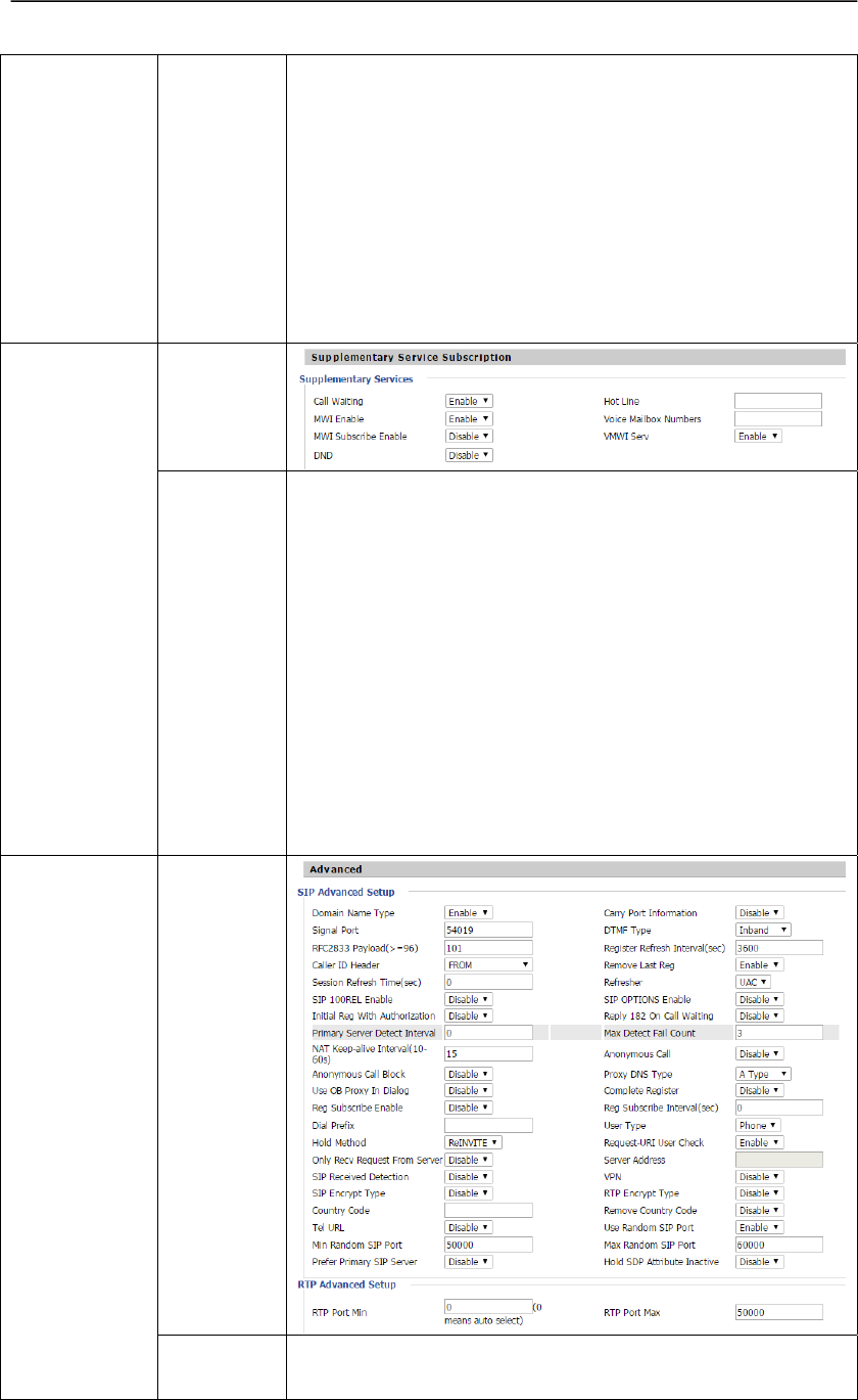
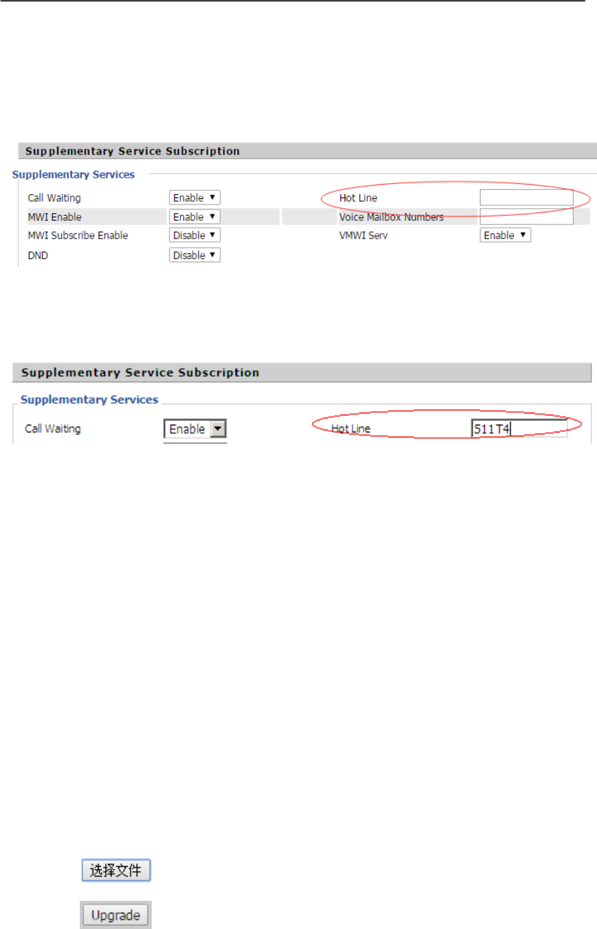
WEB
Interface
Supplementary
Service
Subscription
Settings
Introduction
1)Call Waiting: if or not enable call waiting, by default it is
enabled.
2)Hot Line: Enter the hot line number, after user configure this,
the device will dial out the hot line number automatically when
user pick up the handset or press the speaker button.
If you want to delay some seconds, please add delay time with
T behind the number, for example, 511T4, the device will
delay 4 seconds before dial the number when you pick up the
handset.
3)MWI Enable: If or not enable MWI.
4)Voice MailBox Numbers: enter the voice mail box number.
5)DND: If or not enable DND.
WEB
Interface
Advanced
Setup
1) Domain name Mode: If or not use domain name in the SIP
URI.

User Manual
25
Settings
Introduction
2). Carry Port Information: If or not carry Port information in
the SIP URI.
3) Signal Port: The local port of SIP protocol, default is 5060.
4) DTMF Type: choose the DTMF type from IN_band,
RFC2833 and SIP INFO.
5) RFC2833 Payload (>=96): User can use the default setting.
6) Register Refresh Interval (Second): The interval between
two normal Register messages. You can use the default setting.
7). RTP Port: FTA1101 will select idle port for RTP if you set
“0”, otherwise FTA1101 use the value you set. Generally
speaking, set “0”.
8) Cancel Message Enable: when you set enable, an
unregistered message will be sent before registration, while you
set disable, unregistered message will not be sent before
registration. You should set the option for different Proxy.
9) Session Refresh Time: Set the session refresh time.
10)Refresher: Select from UAC and UAS.
11)Prack Enable:If or not enable prack.
12)SIP Options Enable: If or not enable sip options.
13)Primary SER Detect Interval:Set the primary server detect
interval.
14)Max Detect Fail Count: The max detect fail account.
15)Keep-alive interval (10-60s): the interval that we send an
empty packet to Proxy.
16)Anonymous Call: If or not enable anonymous call.
17)Anonymous Call Block: If or not enable block anonymous
call function.
18)Proxy DNS Type: Select from A Type and DNS SRV.
19)Use OB Proxy In Dialog:If or not use OB proxy in dialog.
20)Reg Subscribe Enable:If or not enable registration
subscribe.
21)Dial Prefix: Define the prefix of the phone number you
dialed.
22)User Type:Define the user type, options are IP and Phone.
23)Only Recv Request From Server:If enable this option,
FTA1101 will only receive the call from the same SIP server.
24)Request URI user check:If or not enable request URI user
check.
25)Hold Method:Select the hold method, options are
ReINVITE and INFO.
User Manual
26
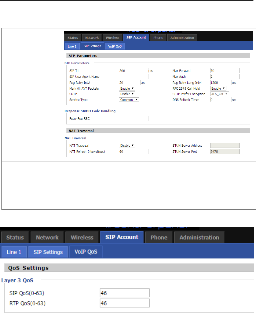
6.4.2 SIP Settings
WEB
Interface
Settings
Introduction
1) SIP Parameters:
This page displays the SIP parameters.
2) NAT Traversal
If you want traverse NAT/Firewall, please enable NAT Traversal and fill
in the corresponding parameters.
6.4.3 VoIP QoS
Some ISP supply QoS services. The QoS services can make the best of improving the quality of
Voice application. You can get the settings from the ISP if they supply QoS services. Please
connect with them if you need it.
User Manual
27
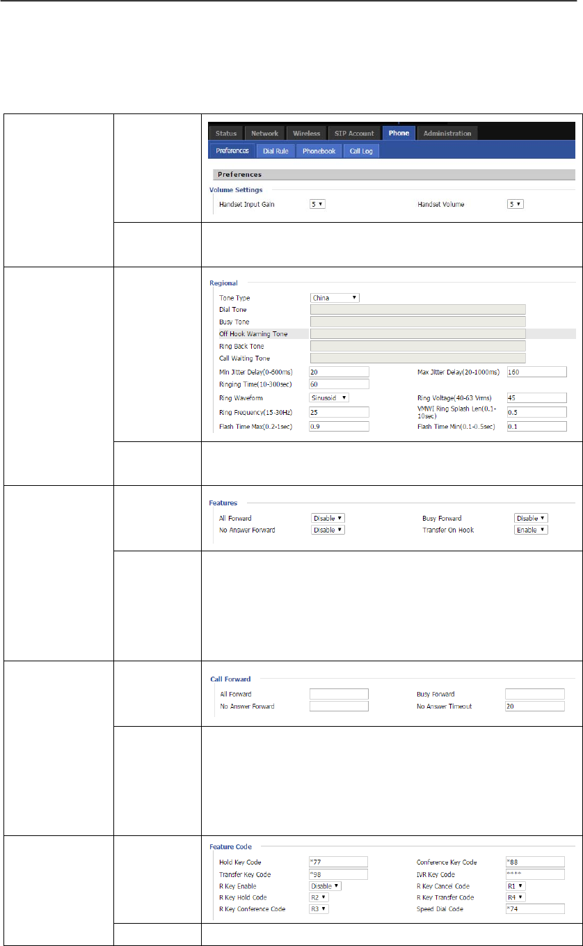
6.5 Phone
6.5.1 Preferences
WEB
Interface
Preferences
Settings
Introduction
1) Handset Input Gain: adjust the input gain from 0-7.
2) Handset volume: adjust the output volume from 0-7.
WEB
Interface
Regional
Settings
Introduction
In this page, user can define tone type and set some
parameters of the FXS1 port.
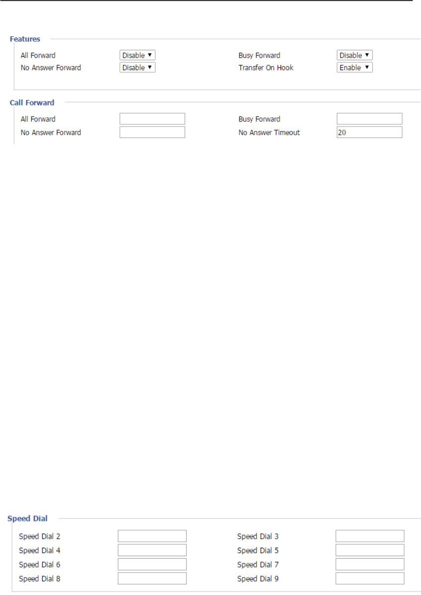
WEB
Interface
Features
Settings
Introduction
All Forward:If or not enable all call forward;
Busy Forward:If or not enable call forward when FXS1 port is
busy;
No Answer Forward: If or not enable call forward when FXS1
port does not answer the call.
WEB
Interface
Call Forward
Settings
Introduction
All Forward:Enter the all call forward destination number.
Busy Forward:Enter the busy call forward destination number.
No Answer Forward:Enter the no answer forward destination
number.
No Answer Timeout:Define the no answer timeout time.
WEB
Interface
Feature Code
Settings The feature code for call hold, conference, transfer and IVR,
User Manual
28
Introduction use can also user R key to perform these functions, for
example, press R and then press 2 to hold a call.
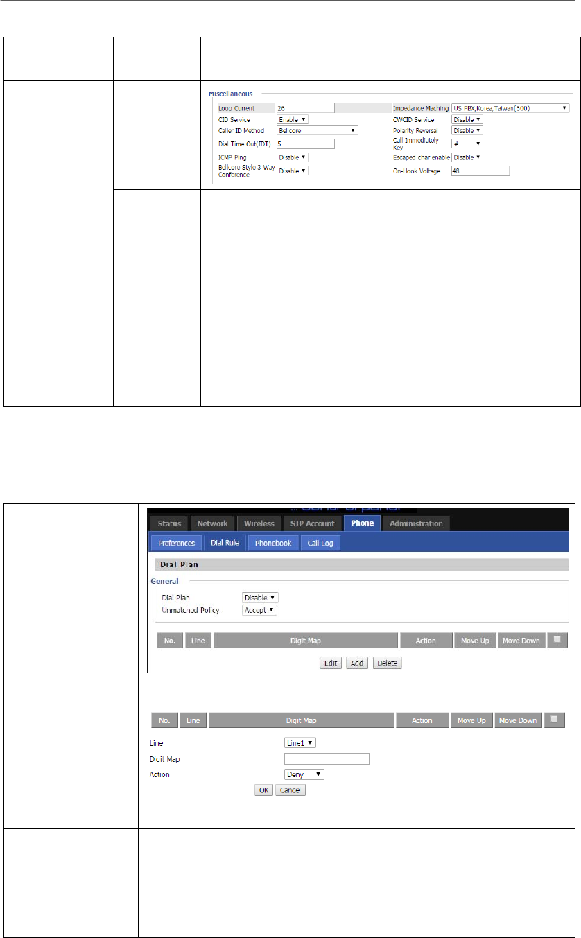
WEB
Interface
Miscellaneous
Settings
Introduction
Codec Loop Current: Set the value for codec loop current.
Impedance Maching: Set impedance value.
CID Service:If or not enable caller ID service.
CWCID Service:If or not enable call waiting caller ID service.
Dial Time Out:Define how long the device waits before
sending out the phone numbers.
Call Immediately Key:Add this key after the phone numbers,
FTA1101 will dial the numbers immediately.
ICMP Ping:If or not enable ICMP ping.
Escaped char enable:If or not enable escaped char.
6.5.2 Dial Rule
If you set a shortcut number for a dial rule, when you dial shortcut number, FTA1101 will realize
whole dial rule immediately.
WEB
Interface
Picture 1
Picture 2
Settings
Introduction
Dial Plan:If or not enable dial plan.
Edit:Click it to edit the dial rule user selected.
Add:Click it to add a new dial rule.
Delete:Click it to delete the dial rule user selected.
After click Add, the webpage will show as Picture 2.
User Manual
29
FXS: Select which FXS port uses the rule.
Digit Map: The digit map sting of dial plan, details please refer to dial
plan user manual.
Action:Choose the action, when user’s dial string matches the dial rule,
the device’s action, deny or dial out.
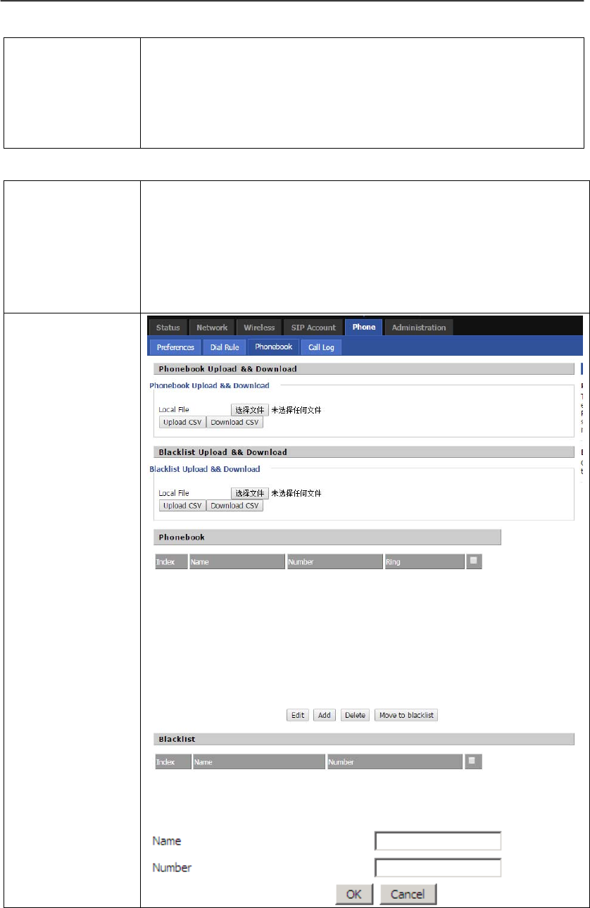
6.5.3 Phonebook
Settings
Introduction
In this configuration interface, you can set the blacklist, enter the name
and phone number you wish to block. User also can upload a piece of
blacklist file.
If user set a black number 2222, 2222 can not call you, but you can call
2222.
Enter the name and Number you can set a blacklist.
WEB
Interface
User Manual
30
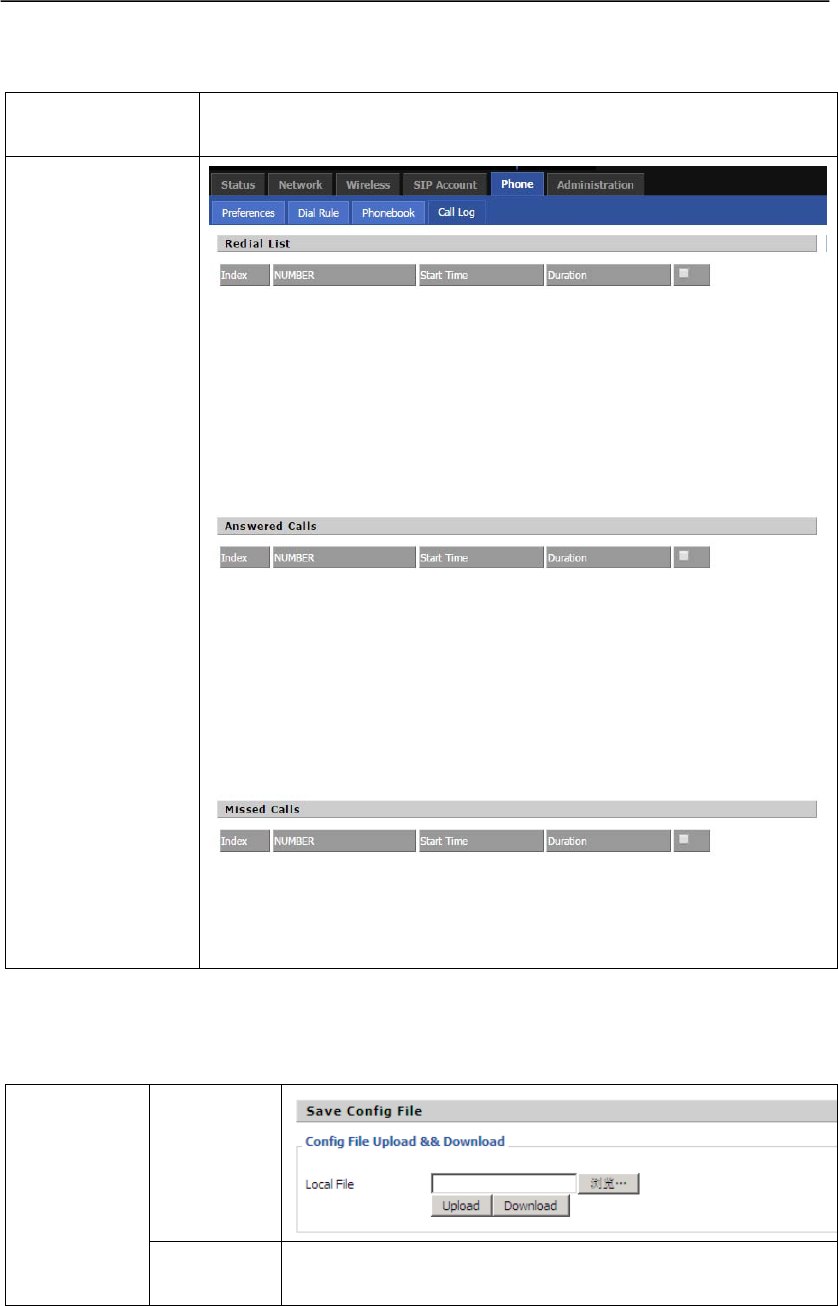
6.5.4 Call Log
Settings
Introduction
User can view FTA1101 call log, including missed, dialed and answered
calls. User can also delete the call logs.
WEB
Interface
6.6 Administration
6.6.1 Management
WEB
Interface
Save Config
File
Settings
Introduction
In this column, user can upload a new configuration file for the
device, also can save the configuration file to local PC.
User Manual
31
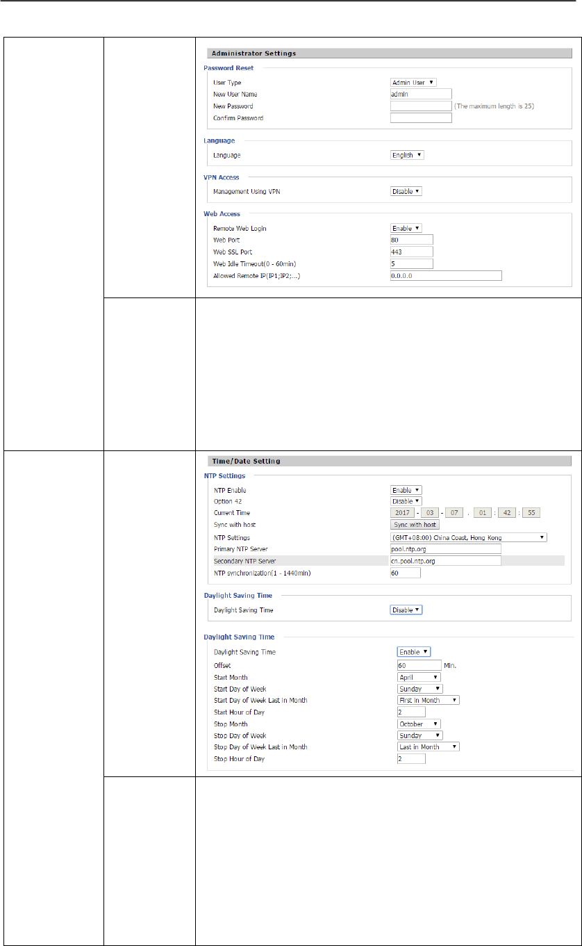
WEB
Interface
Administrator
Settings
Settings
Introduction
1)Password Reset:Reset username and password, user need
select one user level first and then rename the user name and
change the password.
2)Language:Select another language, FTA1101 support
English, Russian, Finnish, Spanish, Chinese and so on.
3)Web Access: Enable or disable web access, user can also
define the web access port and web idle timeout.
WEB
Interface
Time/Date
Settings
Introduction
1)NTP Settings: User can enable the NTP and select time zone
and set NTP server and so on.
2)Daylight Saving Time:If or not enable daylight saving time,
this is the function to bring an hour ahead the normal time.
When enable this option, user can define offset, start/stop
month, start/stop day of week, start/stop day of week last in
month and start/stop hour of day.
User Manual
32
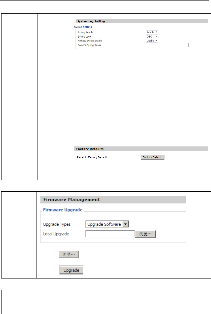
WEB
Interface
System
Log
Setting
Settings
Introduction
1)Syslog Enable: If or not enable system log.
2)Syslog Level:FTA1101 has two log level, INFO and Debug,
in debug level, there will be more information in the system
log.
3)Remote Syslog Enable:If or not enable remote system log.
4)Remote Syslog Server:Enter the IP address of the remote
system log server, FTA1101 will send the system log to the
host. To check system log, user need open syslog server on
your local PC, tftp32 can be used as system log server.
WEB
Interface
Factory
Default
Settings
Introduction
Press the Factory Default button to make the device factory
default.
6.6.2 Firmware Upgrade
WEB
Interface
Settings
Introduction
1) Press to select a firmware file.
2) Press to start upgrading.
6.6.3 Certificates
In this webpage, user can upload https provision SSL certificates or upload the TR069
certificates. FTA1101 has deleted the https provision, and deleted this webpage, Flyingvoice
will add the https provision soon in the new firmware, so we still keep this section.
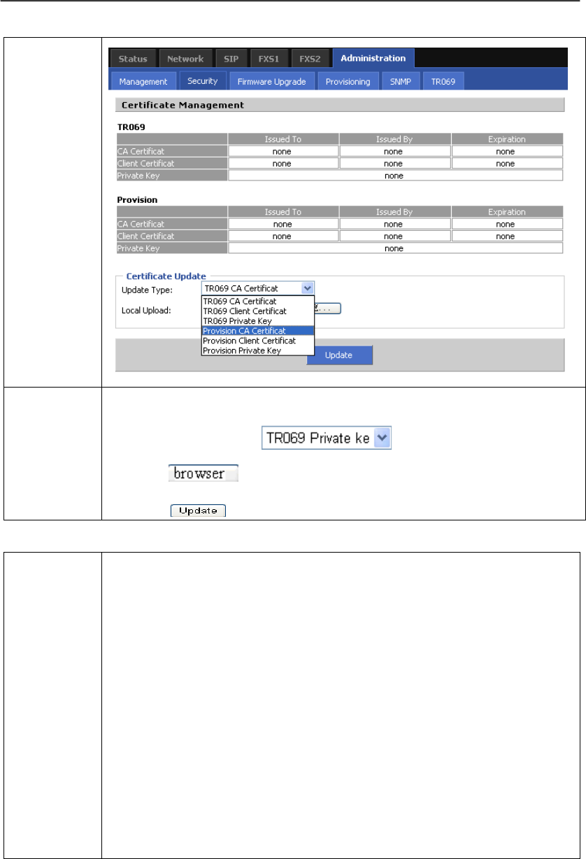
User Manual
33
WEB
Interface
Settings
Introduction
User can upload cert files for TR069 and Provision.
Steps:
1) Choose File Types in
2) Press to browser file.
3) Press to start upgrading.
6.6.4 Provisioning
Generally
Introduction
1) Provisioning allow FTA1101 auto-upgrading or auto-configuring
2) The current FTA1101 supports 2 ways to provision: TFTP and HTTP.
Before testing or using TFTP, user should have tftp server and upgrading
file and configuring file.
Before testing or using HTTP, user should have http server and upgrading
file and configuring file.
Before testing or using HTTPS, user should have https server and
upgrading file and configuring file and CA Certificate file(should same
as https server’s) and Client Certificate file and Private key file(HTTPS
provision will be supported soon)
User can uploading CA Certificate file and Client Certificate file and Private
Key file in Security page.
Notice: Please refer to documentation Provision_User Manual_en_v1.5.pdf
to use this function.
User Manual
34
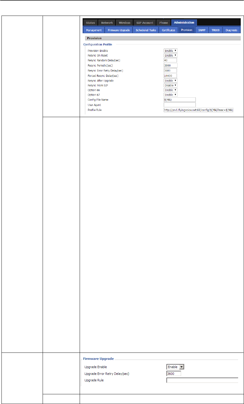
WEB
Interface
Configuration
Profile
Settings
Introduction
1)Provision Enabled:If or not enable provision
2)Resync On Reset:If or not enable resync after DIV378 restart
3)Resync Random Delay:Set the maximum delay for request
the synchronization file, default is 40.
4)Resync Periodic:Set the periodic time for resync, default is
3600s.
5)Resync Error Retry Delay:If the last resync was failure,
FTA1101 will retry resync after the “Resync Error Retry
Delay” time, default is 3600s.
6)Forced Resync Delay:If it’s time to resync, but FTA1101 is
busying now, in this case, FTA1101 will wait for a period
time, the longest is “Forced Resync Delay”, default is
14400s, when the time over, FTA1101 will forced to resync.
7) Resync After Upgrade Attempt:If or not enable
firmware upgrade after resync, by default it is enabled.
8)Option 66:If or not enable DHCP option 66 to override
server. If enable, the parameter “profile rule” will has no effect.
9)Config File Name:It is used for In-house provision mode
only. When use TFTP with option 66 to realize provisioning,
user must input right configuration file name in IP542N's
webpage. When disable Option 66, this parameter has no
effect.
10) Profile Rule: URL of profile provision file
Note that the specified file path is relative to the TFTP server’s
virtual root directory.
WEB
Interface
Firmware
Upgrade
1)Upgrade Enable:If or not enable firmware upgrade via
User Manual
35
Settings
Introduction
provision.
2)Upgrade Error Retry Delay:If the last upgrade fails, FTA1101
will try upgrading again after “Upgrade Error Retry Delay”
period, default is 3600s.
3) Upgrade Rule: URL of upgrade file
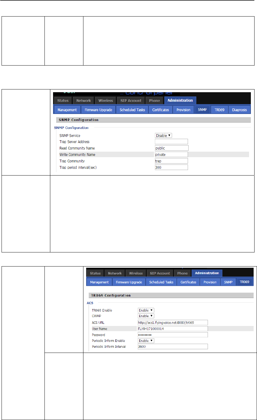
6.6.5 SNMP
WEB
Interface
Settings
Introduction
1)SNMP Enable:If or not enable SNMP
2)Trap Server Address:Enter the trap server address.
3)Read Community Name:string, as an express password between
management progress and agent progress.
4)Write Community Name:String, as an express password between
management progress and agent progress.
5)Trap Community:The community field in trap.
Trap Period interval:The interval of sending trap.
6.6.6 TR069
WEB
Interface
TR069
Configuration
Settings
Introduction
1)TR069 Enable:If or not enable TR069.
2)CWMP:If or not enable TR069
3)ACS URL:The URL of TR069 server.
4)User Name:Enter the user name to connect to TR069 server.
5)Password:Enter the password to connect the TR069 server.
6)Periodic Inform Enable:If or not enable periodic information.
7)Periodic Inform Interval:The interval of sending information
User Manual
36
to TR069 server.
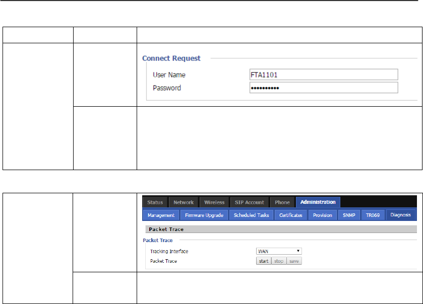
WEB
Interface
Connect
Request
Settings
Introduction
1)User Name: Define the username for the TR069 server
connecting FTA1101.
2)Password: Define the password for TR069 server connecting
FTA1101.
6.6.7 Diagnosis
WEB
Interface
Packet
Trace
Settings
Introduction
Press Start to begin tracing the packet, or press stop to cancel,
also you can press Save to save the packets to your local PC.
7. Functions
7.1 Making Calls
Dial the number directly and wait for 5 seconds (default No Key Entry Timeout).
Dial the number with ending char #, FTA1101 will dial out immediately
Dial the phone number which matches one dial rule, FTA1101 will dial out immediately, no
need to press # or wait for 5 seconds.
7.2 Call Waiting
Step 1.Enable waiting feature in SIP Account→Line1→Supplementary Service→Call Waiting
(default is Enable)
Step 2.While in conversation, user will hear a special stutter tone if there is another incoming call.
Step3.User then can press “*77” (or Flash button)to put the current call party on hold
automatically and switch to the other call. Pressing “*77”(or Flash button) toggles between
two active calls.
7.3 Call Hold
Step 1.While in conversation, pressing the “*77”(or Flash button), will put the remote end on
hold.
Step 2.Pressing the “*77”(or Flash button) again, will release the previously Hold state and

User Manual
37
resume the bi-directional media.
7.4 Call Transferring
FTA1101 supports blind transfer and attended transfer.
7.4.1 Blind Transfer
Assuming that call party A and party B are in conversation, A wants to Blind Transfer B to C
Step 1.Party A dials *98, A will hear dialing tone
Step 2.Dial party C’s number, and press # (or wait for 5 seconds) to call C, then C will ring, A will
be disconnected.
Step 3.If C answer the call, B and C can go on talking.
7.4.2 Attended Transfer
Assuming that call party A and B are in conversation. A wants to Attend Transfer B to C:
Step 1.Party A dials *77 to hold B, A will hear dialing tone
Step 2.Dial party C’s number, and press # (or wait for 5 seconds) to call C, then A will hear
ringing tone.
Step 3.If C answer the call, A will talk with C firstly
Step 4.If C wants to talk with B, A press “*98” to transfer, and then C will talk with B. If C does
not talk with C successfully, A will talk with B again.
7.5 3-way conference call
Assuming that call party A and B are in conversation. A wants to add C to the conference:
Step 1.Party A dials *77 to hold B, A will hear dialing tone
Step 2.Dial party C’s number, and press # (or wait for 5 seconds) to call C, then A will hear
ringing tone.
Step 3.If C answer the call, A will talk with C firstly
Step 4.If C receive the conference, A press “*88” to add C to the conference, and then A,B and C
are in conference.
7.6 Call Forwarding
Step 1. Open Phone→Preferences→Call Forward, enable the one call forward mode and fill
forwarded number
User Manual
38
Step 2: FTA1101 will forward incoming call to the forwarded number according to the settings of
Call Forward and call status
7.7 Direct IP calls
Direct IP calling allows two phones, that is, an ATA with an analog phone and another VoIP Device,
to talk to each other without a SIP proxy. VoIP calls can be made between two phones if:
Both ATA and the other VoIP device (i.e. another ATA or other SIP products) have public IP
addresses, or
Both ATA and the other VoIP device (i.e. another ATA or other SIP products) are on the same
LAN using private or public IP addresses, or
Both ATA and the other VoIP device (i.e. another ATA or other SIP products) can be connected
through a router using public or private IP addresses
To make a direct IP call,
Step 1: Picking up the analog phone or turning on the speaker phone on the analog phone
Step 2: Input the IP address directly with ending char #. E.g. call 192.168.20.34, dial
192*168*20*34#
7.8 Speed dialing
Step 1.Set phone number(E.g.3333) in SIP Account→Line1→Speed Dial, and then save the
changes
Step 2.Dial*74 to active speed dial function
Step 3.Then dial 2 to call 3333, and FTA1101 will dial out immediately.
User Manual
39
7.9 Hotline
Step 1.Set hotline in SIP Account→Line1→Supplementary Service Subscription, you can refer to
the following picture. And then save the changes.
Step 2.Picking up handset or press speaker button, FTA1101 will ring hotline immediately.
If you want to delay some seconds after pick up the handset, please add delay time. For example,
FTA1101 will call 511 after user picks up the handset for 4 seconds.
7.10 Daylight Saving Time
Daylight Saving Time (or summer time as it is called in many countries) is a way of getting more
light out of the day by advancing clocks by some hour during the summer. During Daylight
Saving Time, the sun appears to rise one hour later in the morning, when people are usually asleep
anyway, and sets one hour later in the evening, seeming to stretch the day longer.
Step 1.Open Administration/Management webpage.
Step 2.Enable parameter Daylight Saving Time in Time/Date.
Step 3.Set offset: “-60” means advancing 60min, “60” means delaying 60min.
Step 4.Set starting Month/Week/Day/Hour in Start Month/Start Day of Week Last in
Month/Start Day of Week/Start Hour of Day, analogously set stopping Month/Week/Day/Hour
in Stop Month/Stop Day of Week Last in Month/Stop Day of Week/Stop Hour of Day.
Step 5.Press Saving button to save and press reboot button to active changes.
7.11 Upgrade Firmware
Function is to upgrade firmware in local.
Step 1.Open Administration/Firmware Upgrade webpage
Step 2.Press to browse a firmware file
Step 3.Press to start upgrading
Step 4.When upgrading, there will be prompt like below
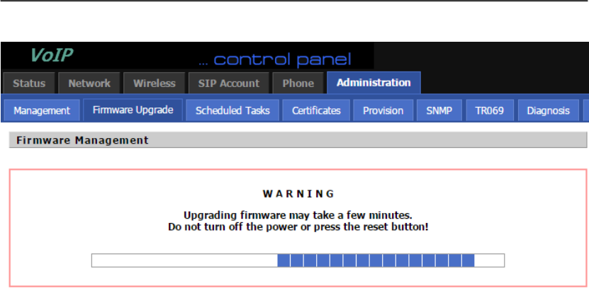
User Manual
40
7.12 Password Control
Function is to reset password.
Step 1.Open Administration/Management webpage
Step 2.Choose password type
Step 3.Input current password (Original Password, default is “admin” for admin level and user for
user level),
Step 4.Input new password in New Password and Password Confirm.
Step 5.Press Save Settings button to save and then press Reboot button to make changes effective.
7.13 Web Access
User can use the two parameters in Web Access to control WAN web login or login port.
WAN Interface Login is to disable/enable user access to web via WAN port;
Web Login Port is to set login port.
7.14 System log
User can view system log in local or in remote.
In local:
Step 1.Open Administration/Management page, System Log Setting column.
Step 2.Choose log level from INFO and Debug, in INFO level, FTA1101 records INFO log, and
in Debug level, FTA1101 records all debug information.
Step 3.Press Save button to save and then press Reboot button to make changes effective.
In remote:
Step 1.Open Administration/Management page, System Log Setting column.
Step 2.Fill system server IP Address or domain name into Syslog Server.
Step 3.Choose log level from INFO and Debug, in INFO level, FTA1101 records INFO log, and
in Debug level, FTA1101 records all debug information.
Step 4.Press Save button to save and then press Reboot button to make changes effective.

User Manual
41
8. Software Feature
Support SIP V2.0(RFC 3261/RFC3262)
Support G.711 (A-Law, μ-Law), G.723, G.722 and G.729A/AB Codes
Support two RJ45 10/100M that one is WAN port and another is LAN port.
Support two RJ-11 for FXS port to connect your analog phone
Support IP address assignment using PPPOE, DHCP and Static IP
IP conflict detection
Support NAT traversal (Static NAT Route or by STUN)
Support Voice Activity Detection(VAD) ,Comfort Noise Generation(CNG) and Echo
cancellation
Adaptive jitter buffer for smooth voice reception
Support direct IP to IP dialing without registration
Support complementary features such as Call hold, Call waiting, Call forwarding, Call
Transfer, Call Block, Hotline, Message Waiting Indicator and DTMF Realy (In-band,
RFC2833 and SIP INFO) etc.
Support MAC address cloning
Support IEEE802.1Q VLAN/802.1P and IP TOS
Provide easy configuration through manual operation ( Web interface and IVR-driven interface)
or auto provisioning via TFTP or HTTP
Support syslog client

User Manual
42
Federal Communications Commission (FCC) Statement
This device complies with part 15 of the FCC Rules. Operation is subject to the following two
conditions: (1) This device may not cause harmful interference, and (2) this device must
accept any interference received, including interference that may cause undesired operation.
Note: This equipment has been tested and found to comply with the limits for a Class B digital
device, pursuant to part 15 of the FCC Rules. These limits are designed to provide reasonable
protection against harmful interference in a residential installation. This equipment generates,
uses and can radiate radio frequency energy and, if not installed and used in accordance with
the instructions, may cause harmful interference to radio communications. However, there is
no guarantee that interference will not occur in a particular installation. If this equipment does
cause harmful interference to radio or television reception, which can be determined by turning
the equipment off and on, the user is encouraged to try to correct the interference by one or
more of the following measures:
●Reorient or relocate the receiving antenna.
●Increase the separation between the equipment and receiver.
●Connect the equipment into an outlet on a circuit different from that to which the receiver is
connected.
●Consult the dealer or an experienced radio/TV technician for help.
Warning: Changes or modifications made to this device not expressly approved by
Flyingvoice Network Technology Co., Ltd may void the FCC authorization to operate this
device.
Note: The manufacturer is not responsible for any radio or TV interference caused by
unauthorized modifications to this equipment. Such modifications could void the user’s
authority to operate the equipment.
RF exposure statement:
The transmitter must not be colocated or operated in conjunction with any other antenna or
transmitter. This equipment complies with the FCC RF radiation exposure limits set forth for
an uncontrolled environment. This equipment should be installed and operated with a
minimum distance of 20cm between the radiator and any part of your body.