Flyingvoice Network Technology FWR9202 VoIP Wireless Router User Manual The G801
Flyingvoice Network Technology Co., Ltd VoIP Wireless Router The G801
User manual

Copy Right 2017 All Rights Reserved by FLYINGVOICE TECHNOLOG LIMITED
V1.0
The page 1 of 78
Revision time: 2017-06-16 15:00
The FWR9202
High Speed Router
User’s Guide
V1.0
indoor use only

Copy Right 2017 All Rights Reserved by FLYINGVOICE TECHNOLOG LIMITED
V1.0
The page 2 of 78
Revision time: 2017-06-16 15:00
Table of Contents
1 Preface..............................................................................................................................................................................................................................................................................................................................5
1.1 Declaration of Conformity...................................................................................................................................................................................................................................................................................5
1.1.1 Part 15 FCC Rules................................................................................................................................................................................................................................................................................... 5
1.1.2 Class B Digital Device or Perpheral........................................................................................................................................................................................................................................................5
1.2 GNU GPL Information........................................................................................................................................................................................................................................................................................ 6
2 Overview.......................................................................................................................................................................................................................................................................................................................... 7
2.1 FWR9202............................................................................................................................................................................................................................................................................................................. 7
2.2 LED Indicators.....................................................................................................................................................................................................................................................................................................7
2.2.1 FWR9202 LED Indicators.......................................................................................................................................................................................................................................................................7
2.3 Hardware Installation...........................................................................................................................................................................................................................................................................................9
2.4 Voice Prompt......................................................................................................................................................................................................................................................................................................10
3 Configuring Basic Settings............................................................................................................................................................................................................................................................................................ 13
3.1 Two-Level Management....................................................................................................................................................................................................................................................................................13
3.2 Accessing Web Page..........................................................................................................................................................................................................................................................................................13
3.2.1 From LAN port...................................................................................................................................................................................................................................................................................... 13
3.2.2 From WAN port.....................................................................................................................................................................................................................................................................................14
3.3 Web Page........................................................................................................................................................................................................................................................................................................... 15
3.4 Setting up the Time Zone.................................................................................................................................................................................................................................................................................. 15
3.5 Setting up the Internet Connection.................................................................................................................................................................................................................................................................... 16
3.6 Setting up the Wireless Connection...................................................................................................................................................................................................................................................................17
3.6.1 Enable Wireless and Setting SSID........................................................................................................................................................................................................................................................ 17
3.6.2 Encryption..............................................................................................................................................................................................................................................................................................17
3.7 Register.............................................................................................................................................................................................................................................................................................................. 18
3.7.1 Get the Accounts....................................................................................................................................................................................................................................................................................18
3.7.2 Connections........................................................................................................................................................................................................................................................................................... 18
3.7.3 Configuration SIP from Webpage..........................................................................................................................................................................................................................................................19
3.7.4 View the Register Status........................................................................................................................................................................................................................................................................19
3.8 Make Call...........................................................................................................................................................................................................................................................................................................20
3.8.1 Calling phone or extension numbers..................................................................................................................................................................................................................................................... 20
3.8.2 Direct IP calls.........................................................................................................................................................................................................................................................................................20
3.8.3 Call Hold................................................................................................................................................................................................................................................................................................20
3.8.4 Blind Transfer........................................................................................................................................................................................................................................................................................ 20
3.8.5 Attended Transfer.................................................................................................................................................................................................................................................................................. 21
3.8.6 Conference............................................................................................................................................................................................................................................................................................. 21
4 Web Configuration.........................................................................................................................................................................................................................................................................................................22
4.1 Login.................................................................................................................................................................................................................................................................................................................. 22
4.2 Status..................................................................................................................................................................................................................................................................................................................22

Copy Right 2017 All Rights Reserved by FLYINGVOICE TECHNOLOG LIMITED
V1.0
The page 3 of 78
Revision time: 2017-06-16 15:00
4.3 Network&Security............................................................................................................................................................................................................................................................................................. 23
4.3.1 WAN...................................................................................................................................................................................................................................................................................................... 23
4.3.2 LAN....................................................................................................................................................................................................................................................................................................... 28
4.3.3 MAC Clone............................................................................................................................................................................................................................................................................................30
4.3.4 VPN........................................................................................................................................................................................................................................................................................................30
4.3.5 DMZ.......................................................................................................................................................................................................................................................................................................31
4.3.6 DDNS Setting........................................................................................................................................................................................................................................................................................ 31
4.3.7 Port Forward.......................................................................................................................................................................................................................................................................................... 32
4.3.8 Advance................................................................................................................................................................................................................................................................................................. 33
4.3.9 Port Setting............................................................................................................................................................................................................................................................................................ 33
4.3.10 QoS......................................................................................................................................................................................................................................................................................................34
4.3.11 Routing................................................................................................................................................................................................................................................................................................34
4.4 Wireless..............................................................................................................................................................................................................................................................................................................35
4.4.1 Basic.......................................................................................................................................................................................................................................................................................................35
4.4.2 Wireless Security................................................................................................................................................................................................................................................................................... 37
4.4.3 WMM.....................................................................................................................................................................................................................................................................................................40
4.4.4 WDS.......................................................................................................................................................................................................................................................................................................40
4.4.5 WPS....................................................................................................................................................................................................................................................................................................... 41
4.4.6 Station Info............................................................................................................................................................................................................................................................................................ 42
4.4.7 Advanced............................................................................................................................................................................................................................................................................................... 42
4.5 Wireless 5G........................................................................................................................................................................................................................................................................................................44
4.5.1 Basic.......................................................................................................................................................................................................................................................................................................44
4.5.2 Wireless Security................................................................................................................................................................................................................................................................................... 46
4.5.3 WMM.....................................................................................................................................................................................................................................................................................................46
4.5.4 WDS.......................................................................................................................................................................................................................................................................................................46
4.5.5 WPS....................................................................................................................................................................................................................................................................................................... 46
4.5.6 Station Info............................................................................................................................................................................................................................................................................................ 47
4.5.7 Advanced............................................................................................................................................................................................................................................................................................... 47
4.6 SIP......................................................................................................................................................................................................................................................................................................................48
4.6.1 SIP Settings............................................................................................................................................................................................................................................................................................ 48
4.6.2 VoIP Qos................................................................................................................................................................................................................................................................................................ 49
4.7 FXS1.................................................................................................................................................................................................................................................................................................................. 50
4.7.1 SIP Account........................................................................................................................................................................................................................................................................................... 50
4.7.2 Preferences.............................................................................................................................................................................................................................................................................................54
4.7.3 Dial Plan.................................................................................................................................................................................................................................................................................................57
4.7.4 Blacklist................................................................................................................................................................................................................................................................................................. 59
4.7.5 Call Log................................................................................................................................................................................................................................................................................................. 59
4.8 FXS2.................................................................................................................................................................................................................................................................................................................. 61
4.9 Security.............................................................................................................................................................................................................................................................................................................. 61
4.9.1 Filtering Setting..................................................................................................................................................................................................................................................................................... 61
4.9.2 Content Filtering....................................................................................................................................................................................................................................................................................62

Copy Right 2017 All Rights Reserved by FLYINGVOICE TECHNOLOG LIMITED
V1.0
The page 4 of 78
Revision time: 2017-06-16 15:00
4.10 Application...................................................................................................................................................................................................................................................................................................... 63
4.10.1 UPnP....................................................................................................................................................................................................................................................................................................63
4.10.2 IGMP...................................................................................................................................................................................................................................................................................................63
4.10.3 MLD.................................................................................................................................................................................................................................................................................................... 64
4.11 Storage.............................................................................................................................................................................................................................................................................................................64
4.11.1 Disk Management............................................................................................................................................................................................................................................................................... 64
4.11.2 FTP Setting..........................................................................................................................................................................................................................................................................................65
4.11.3 Smb Setting......................................................................................................................................................................................................................................................................................... 65
4.12 Administration.................................................................................................................................................................................................................................................................................................66
4.12.1 Management........................................................................................................................................................................................................................................................................................66
4.12.2 Firmware Upgrade.............................................................................................................................................................................................................................................................................. 69
4.12.3 Provision............................................................................................................................................................................................................................................................................................. 69
4.12.4 SNMP.................................................................................................................................................................................................................................................................................................. 70
4.12.5 TR069..................................................................................................................................................................................................................................................................................................71
4.12.6 Diagnoisis............................................................................................................................................................................................................................................................................................72
4.12.7 Operation Mode.................................................................................................................................................................................................................................................................................. 72
4.13 System Log......................................................................................................................................................................................................................................................................................................73
4.14 Logout............................................................................................................................................................................................................................................................................................................. 73
4.15 Reboot............................................................................................................................................................................................................................................................................................................. 74
5 Trouble shooting of the guide........................................................................................................................................................................................................................................................................................ 75
5.1 Setting your PC gets IP automatically...............................................................................................................................................................................................................................................................75
5.2 Can not connect to the configuration Website.................................................................................................................................................................................................................................................. 76
5.3 Forget the Password...........................................................................................................................................................................................................................................................................................76
5.4 Fast Bridge Setting.............................................................................................................................................................................................................................................................................................76

Copy Right 2017 All Rights Reserved by FLYINGVOICE TECHNOLOG LIMITED
V1.0
The page 5 of 78
Revision time: 2017-06-16 15:00
1Preface
Thank
Thank you
you for
for choosing
choosing FWR9202
FWR9202 wireless
wireless router
router with
with VoIP.
VoIP. This
This product
product will
will allow
allow you
you to
to make
make ATA
ATA call
call using
using your
your broadband
broadband connection,
connection, and
and
provides
provides Wi-Fi
Wi-Fi router
router function.
function.
This
This manual
manual provides
provides basic
basic information
information on
on how
how to
to install
install and
and connect
connect FWR9202
FWR9202 wireless
wireless router
router with
with VoIP
VoIP to
to the
the Internet.
Internet. It
It also
also includes
includes
features
features and
and functions
functions of
of wireless
wireless router
router with
with VoIP
VoIP components,
components, and
and how
how to
to use
use it
it correctly.
correctly.
Before
Before you
you can
can connect
connect FWR9202
FWR9202 to
to the
the Internet
Internet and
and use
use it,
it, you
you must
must have
have a
ahigh-speed
high-speed broadband
broadband connection
connection installed.
installed. A
Ahigh-speed
high-speed
connection
connection includes
includes environments
environments such
such as
as DSL,
DSL, cable
cable modem,
modem, and
and a
aleased
leased line.
line.
FWR9202
FWR9202 wireless
wireless router
router with
with VoIP
VoIP is
is a
astand-alone
stand-alone device,
device, which
which requires
requires no
no PC
PC to
to make
make Internet
Internet calls.
calls. This
This product
product guarantees
guarantees clear
clear and
and
reliable
reliable voice
voice quality
quality on
on Internet,
Internet, which
which is
is fully
fully compatible
compatible with
with SIP
SIP industry
industry standard
standard and
and able
able to
to interoperate
interoperate with
with many
many other
other SIP
SIP devices
devices and
and
software
software on
on the
the market.
market.
1.1 Declaration of Conformity
1.1.1 Part 15 FCC Rules
This
This device
device complies
complies with
with Part
Part 15
15 of
of the
the FCC
FCC Rules.
Rules. Operation
Operation is
is subject
subject to
to the
the following
following two
two conditions:
conditions:
T
This
his device
device may
may not
not cause
cause harmful
harmful interference,
interference, and
and
This
This device
device must
must accept
accept any
any interference
interference received,
received, including
including interference
interference that
that may
may cause
cause undesired
undesired operation.
operation.
1.1.2 Class B Digital Device or Perpheral
Note:
Note: C
Changes
hanges or
or modifications
modifications not
not expressly
expressly approved
approved by
by the
the party
party responsible
responsible for
for compliance
compliance could
could void
void the
the user
user’
’s
sauthority
authority to
to operate
operate the
the
equipment.
equipment.
This
This equipment
equipment has
has been
been tested
tested and
and found
found to
to comply
comply with
with the
the limits
limits for
for a
aClass
Class B
Bdigital
digital device,
device, pursuant
pursuant to
to Part
Part 15
15 of
of the
the FCC
FCC Rules.
Rules. These
These
limits
limits are
are designed
designed to
to provide
provide reasonable
reasonable protection
protection against
against harmful
harmful interference
interference in
in a
aresidential
residential installation.
installation. This
This equipment
equipment generates,
generates, uses
uses
and
and can
can radiate
radiate radio
radio frequency
frequency energy
energy and,
and, if
if not
not installed
installed and
and used
used in
in accordance
accordance with
with the
the instructions,
instructions, may
may cause
cause harmful
harmful interference
interference to
to
radio
radio communications.
communications. However,
However, there
there is
is no
no guarantee
guarantee that
that interference
interference will
will not
not occur
occur in
in a
aparticular
particular installation.
installation.
If
If this
this equipment
equipment does
does cause
cause harmful
harmful interference
interference to
to radio
radio or
or television
television reception,
reception, which
which can
can be
be determined
determined by
by turning
turning the
the equipment
equipment off
off and
and on,
on,
the
the user
user is
is encouraged
encouraged to
to try
try to
to correct
correct the
the interference
interference by
by one
one or
or more
more of
of the
the following
following measures:
measures:

Copy Right 2017 All Rights Reserved by FLYINGVOICE TECHNOLOG LIMITED
V1.0
The page 6 of 78
Revision time: 2017-06-16 15:00
1.
1. Reorient
Reorient or
or relocate
relocate the
the receiving
receiving antenna.
antenna.
2.
2. Increase
Increase the
the separation
separation between
between the
the equipment
equipment and
and receiver.
receiver.
3.
3. Connect
Connect the
the equipment
equipment into
into an
an outlet
outlet on
on a
acircuit
circuit different
different from
from that
that to
to which
which the
the receiver
receiver is
is connected.
connected.
4.
4. Consult
Consult the
the dealer
dealer or
or an
an experienced
experienced radio/TV
radio/TV technician
technician for
for help.
help.
1.2 GNU GPL Information
FWR9202
FWR9202 firmware
firmware contains
contains third-party
third-party software
software under
under the
the GNU
GNU General
General Public
Public License
License (GPL).
(GPL). FLYINGVOICE
FLYINGVOICE uses
uses software
software under
under the
the specific
specific
terms
terms of
of the
the GPL.
GPL. Please
Please refer
refer to
to the
the GPL
GPL for
for the
the exact
exact terms
terms and
and conditions
conditions of
of the
the license.
license. The
The original
original GPL
GPL license,
license, source
source code
code of
of
components
components licensed
licensed under
under GPL
GPL and
and used
used in
in Yealink
Yealink products
products can
can be
be downloaded
downloaded online:
online:
http://www.flyingvoice.com/index.php?m=content&c=index&a=lists&catid=169
http://www.flyingvoice.com/index.php?m=content&c=index&a=lists&catid=169

Copy Right 2017 All Rights Reserved by FLYINGVOICE TECHNOLOG LIMITED
V1.0
The page 7 of 78
Revision time: 2017-06-16 15:00
2Overview
Before
Before you
you use
use the
the high
high speed
speed router,
router, please
please get
get acquainted
acquainted with
with the
the LED
LED indicators
indicators and
and connectors
connectors first.
first.
2.1 FWR9202
FWR9202
FWR9202
WAN
WAN
1xGE
1xGE in
in RJ45
RJ45
LAN
LAN
4xGE
4xGE in
in RJ45
RJ45
WiFi
WiFi
2X2
2X2 2.4G
2.4G 802.11
802.11 b/g/n(300
b/g/n(300 Mbps)
Mbps)
2X2
2X2 5G
5G 802.11ac
802.11ac (867
(867 Mbps)
Mbps)
USB
USB
1X
1X USB
USB 2.0
2.0
VoIP
VoIP
2xFXS
2xFXS in
in RJ11
RJ11
PoE
PoE
No
No
Yes
Yes
Power
Power Adapter
Adapter
12V/2A
12V/2A
15V/3A
15V/3A
Trade
Trade Mark:
Mark: Flyingvoive
Flyingvoive.
.
2.2 LED Indicators
2.2.1 FWR9202 LED Indicators
Copy Right 2017 All Rights Reserved by FLYINGVOICE TECHNOLOG LIMITED
V1.0
The page 8 of 78
Revision time: 2017-06-16 15:00
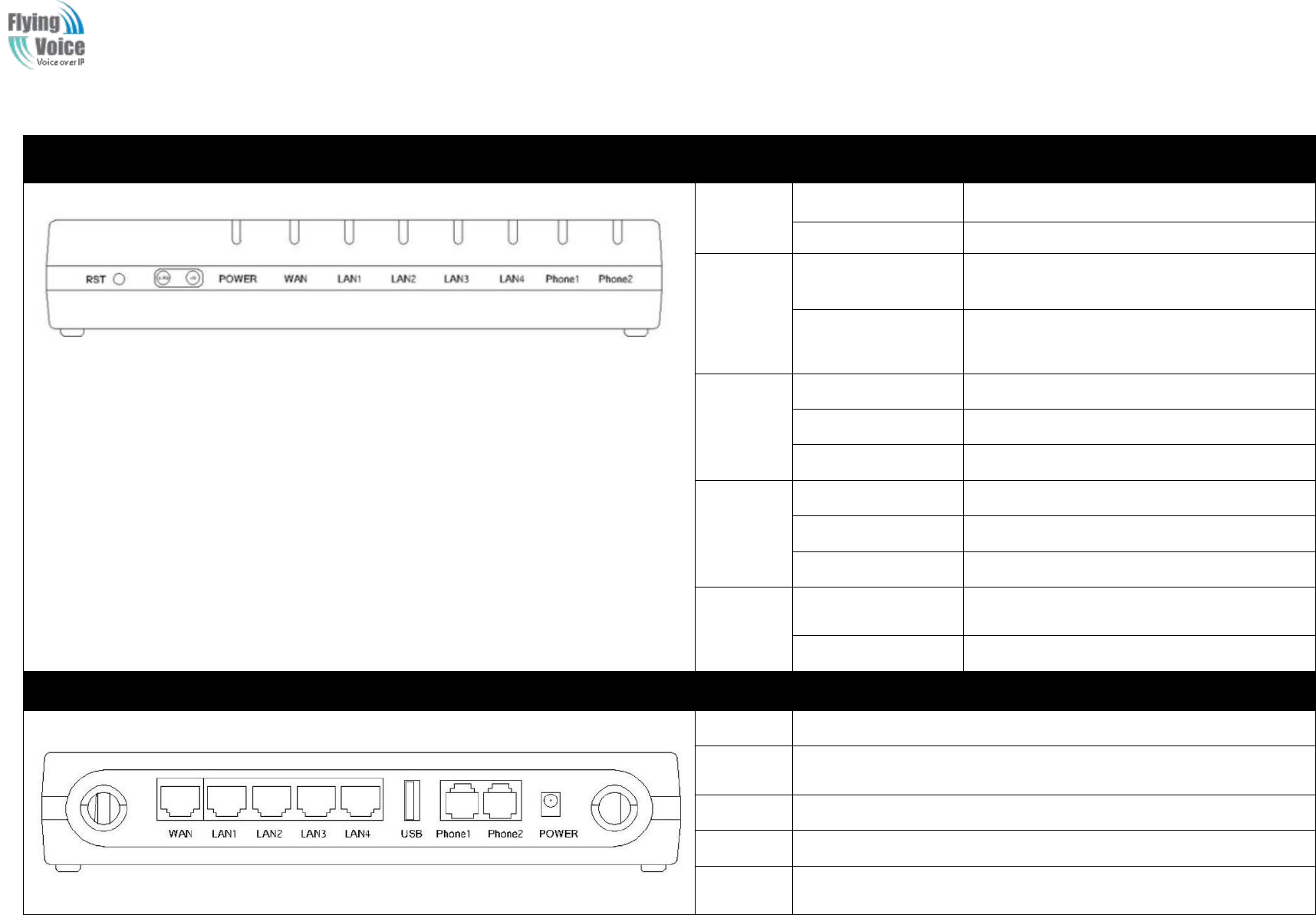
Front Panel
LED
Status
Explanation
PHONE
PHONE
1/2
1/2
Blinking(Green)
Blinking(Green)
Not
Not registered.
registered.
On
On (Green)
(Green)
Registered
Registered
WLAN
WLAN
On
On (
(Green
Green)
)
Wireless
Wireless access
access point
point is
is ready.
ready.
Blinking
Blinking(Green)
(Green)
It
It will
will blink
blink while
while wireless
wireless traffic
traffic goes
goes
through.
through.
LAN
LAN
1/2/3/4
1/2/3/4
On
On (Green)
(Green)
The
The port
port is
is connected
connected with
with 100Mbps.
100Mbps.
Off
Off
The
The port
port is
is disconnected.
disconnected.
Blinking
Blinking(Green)
(Green)
The
The data
data is
is transmitting.
transmitting.
WAN
WAN
On
On(Green)
(Green)
The
The port
port is
is connected
connected with
with 100Mbps.
100Mbps.
Off
Off
The
The port
port is
is disconnected.
disconnected.
Blinking
Blinking(Green)
(Green)
It
It will
will blink
blink while
while transmitting
transmitting data.
data.
POWER
POWER
On(
On(Green
Green)
)
The
The router
router is
is powered
powered on
on and
and running
running
normally.
normally.
Off
Off
The
The router
router is
is powered
powered off.
off.
Rear Panel
Interfac
e
Description
ON/OFF
ON/OFF
Power
Power Switch.
Switch.
DC
DC
12
12V/2A
V/2A
Connector
Connector for
for a
apower
power adapter.
adapter.
FXS
FXS
Connect
Connect to
to the
the phone.
phone.
WAN
WAN
Connector
Connector for
for accessing
accessing the
the Internet.
Internet.
LAN
LAN
(1/2/3/4)
(1/2/3/4)
Connectors
Connectors for
for local
local networked
networked devices.
devices.
FWR9202 Front Panel

Copy Right 2017 All Rights Reserved by FLYINGVOICE TECHNOLOG LIMITED
V1.0
The page 9 of 78
Revision time: 2017-06-16 15:00
2.3 Hardware Installation
Before
Before starting
starting to
to configure
configure the
the router,
router, you
you have
have to
to connect
connect your
your devices
devices correctly.
correctly.
Step
Step 1.
1.Connect
Connect Line
Line port
port to
to land
land line
line jack
jack with
with a
aRJ-11
RJ-11 cable.
cable.
Step
Step 2.
2.Connect
Connect the
the WAN
WAN port
port to
to a
amodem
modem or
or switch
switch or
or router
router or
or Internet
Internet with
with an
an Ethernet
Ethernet cable.
cable.
Step
Step 3.
3.Connect
Connect one
one port
port of
of 4
4LAN
LAN port
ports
sto
to your
your computer
computer with
with a
aRJ-45
RJ-45 cable.
cable. This
This device
device allows
allows you
you to
to connect
connect 4
4PCs
PCs directly.
directly.
Step
Step 4.
4.Connect
Connect one
one end
end of
of the
the power
power cord
cord to
to the
the power
power port
port of
of this
this device.
device. Connect
Connect the
the other
other end
end to
to the
the wall
wall outlet
outlet of
of electricity.
electricity.
Step
Step 5.Push
5.Push the
the ON/OFF
ON/OFF button
button to
to p
power
ower on
on the
the router.
router.
Step
Step 6.
6.Check
Check the
the Power
Power and
and WAN,
WAN, LAN
LAN LEDs
LEDs to
to assure
assure network
network connections.
connections.
Warning: Please do not attempt to use other different power adapter or cut off power supply during configuration or updating the device VoIP home
gateway. Using other power adapter may damage the device and will void the manufacturer warranty.
Warning: changes or modifications not expressly approved by the party responsible for compliance could void the user’s authority to operate the
equipment.
This equipment has been tested and found to comply with the limits for a Class B digital device, pursuant to Part 15 of the FCC Rules. These limits
are designed to provide reasonable protection against harmful interference in a residential installation. This equipment generates, uses and can
radiate radio frequency energy and, if not installed and used in accordance with the instructions, may cause harmful interference to radio
communications. However, there is no guarantee that interference will not occur in a particular installation.
If this equipment does cause harmful interference to radio or television reception, which can be determined by turning the equipment off and on,
the user is encouraged to try to correct the interference by one or more of the following measures:
-- Reorient or relocate the receiving antenna.
-- Increase the separation between the equipment and receiver.
-- Connect the equipment into an outlet on a circuit different from that to which the receiver is connected.
-- Consult the dealer or an experienced radio/TV technician for help.

Copy Right 2017 All Rights Reserved by FLYINGVOICE TECHNOLOG LIMITED
V1.0
The page 10 of 78
Revision time: 2017-06-16 15:00
2.4 Voice Prompt
In
In any
any circumstance,
circumstance, press
pressing
ing the
the following
following command
command to
to enter
enter relevant
relevant function.
function. T
The
he following
following table
table lists
lists command,
command, and
and description.
description.
Voice
Voice Menu
Menu Setting
Setting Options
Options
Operation
Operation code
code
Contents
Contents
1
1
Step
Step 1.Pick
1.Pick up
up phone
phone and
and press
press “
“****
****”
”to
to start
start IVR
IVR
Step
Step 2.Choose
2.Choose “
“1
1”
”,
,and
and FWR9202
FWR9202 report
report the
the current
current WAN
WAN port
port connection
connection type
type
Step
Step 3.Prompt
3.Prompt "Please
"Please enter
enter password
password”
”,
,user
user need
need to
to input
input password
password with
with end
end char
char #
#if
if user
user want
want to
to configuration
configuration WAN
WAN
port
port connection
connection type.
type.
2
2
Step
Step 1.Pick
1.Pick up
up phone
phone and
and press
press “
“****
****”
”to
to start
start IVR
IVR
Step
Step 2.Choose
2.Choose “
“2
2”
”,
,and
and FWR9202
FWR9202 report
report current
current WAN
WAN Port
Port IP
IP Address
Address
Step
Step 3.Input
3.Input the
the new
new WAN
WAN port
port IP
IP address
address and
and with
with the
the end
end char
char #,
#,
using
using “
“*
*”
”to
to replace
replace “
“.
.”
”,
,user
user can
can input
input 192*168*20*168
192*168*20*168 to
to set
set the
the new
new IP
IP address
address 192.168.20.168
192.168.20.168
press
press #
#key
key to
to indicate
indicate that
that you
you have
have finished
finished
Step
Step 4.Report
4.Report “
“operation
operation successful
successful”
”if
if user
user operation
operation properly.
properly.
Note:
Note: If
If you
you want
want to
to quit
quit by
by the
the wayside,
wayside, press
press “
“**
**”
”.
.
3
3
Step
Step 1.Pick
1.Pick up
up phone
phone and
and press
press “
“****
****”
”to
to start
start IVR
IVR
Step
Step 2.Choose
2.Choose “
“3
3”
”,
,and
and FWR9202
FWR9202 report
report current
current WAN
WAN port
port subnet
subnet mask
mask
Step
Step 3.Input
3.Input a
anew
new WAN
WAN port
port subnet
subnet mask
mask and
and with
with the
the end
end char
char #
#
using
using “
“*
*”
”to
to replace
replace “
“.
.”
”,
,user
user can
can input
input 255*255*255*0
255*255*255*0 to
to set
set the
the new
new WAN
WAN port
port subnet
subnet mask
mask 255.255.255.0
255.255.255.0
press
press #
#key
key to
to indicate
indicate that
that you
you have
have finished
finished
3)
3) Report
Report “
“operation
operation successful
successful”
”if
if user
user operation
operation properly.
properly.
4
4
Step
Step 1.Pick
1.Pick up
up phone
phone and
and press
press “
“****
****”
”to
to start
start IVR
IVR
Step
Step 2.Choose
2.Choose “
“4
4”
”,
,and
and FWR9202
FWR9202 report
report current
current gateway
gateway
Step
Step 3.Input
3.Input the
the new
new gateway
gateway and
and with
with the
the end
end char
char #
#
using
using “
“*
*”
”to
to replace
replace “
“.
.”
”,
,user
user can
can input
input 192*168*20*1
192*168*20*1 to
to set
set the
the new
new gateway
gateway 192.168.20.1
192.168.20.1
press
press #
#(pound)
(pound) key
key to
to indicate
indicate that
that you
you have
have finished
finished
3)
3) Report
Report “
“operation
operation successful
successful”
”if
if user
user operation
operation properly.
properly.
Note:
Note: If
If you
you want
want to
to quit
quit by
by the
the wayside,
wayside, press
press “
“**
**”
”.
.

Copy Right 2017 All Rights Reserved by FLYINGVOICE TECHNOLOG LIMITED
V1.0
The page 11 of 78
Revision time: 2017-06-16 15:00
5
5
Step
Step 1.Pick
1.Pick up
up phone
phone and
and press
press “
“****
****”
”to
to start
start IVR
IVR
Step
Step 2.Choose
2.Choose “
“5
5”
”,
,and
and FWR9202
FWR9202 report
report current
current DNS
DNS
Step
Step 3.Input
3.Input the
the new
new DNS
DNS and
and with
with the
the end
end char
char #
#
using
using “
“*
*”
”to
to replace
replace “
“.
.”
”,
,user
user can
can input
input 192*168*20*1
192*168*20*1 to
to set
set the
the new
new gateway
gateway 192.168.20.1
192.168.20.1
press
press #
#(pound)
(pound) key
key to
to indicate
indicate that
that you
you have
have finished
finished
3)
3) Report
Report “
“operation
operation successful
successful”
”if
if user
user operation
operation properly.
properly.
6
6
Step
Step 1.Pick
1.Pick up
up phone
phone and
and press
press “
“****
****”
”to
to start
start IVR
IVR
Step
Step 2.Choose
2.Choose “
“6
6”
”,
,and
and FWR9202
FWR9202 report
report “
“Factory
Factory Reset
Reset”
”
Step
Step 3.Prompt
3.Prompt "Please
"Please enter
enter password",
password", the
the method
method of
of inputting
inputting password
password is
is the
the same
same as
as operation
operation 1.
1.
If
If you
you want
want to
to quit
quit by
by the
the wayside,
wayside, press
press “
“*
*”
”.
.
Step
Step 4.Prompt
4.Prompt “
“operation
operation successful
successful”
”if
if password
password is
is right
right and
and then
then FWR9202
FWR9202 will
will be
be factory
factory setting.
setting.
Step
Step 5.Press
5.Press “
“7
7”
”reboot
reboot to
to make
make changes
changes effective.
effective.
7
7
Step
Step 1.Pick
1.Pick up
up phone
phone and
and press
press “
“****
****”
”to
to start
start IVR
IVR
Step
Step 2.Choose
2.Choose “
“7
7”
”,
,and
and FWR9202
FWR9202 report
report “
“Reboot
Reboot”
”
Step
Step 3.Prompt
3.Prompt "Please
"Please enter
enter password",
password", the
the method
method of
of inputting
inputting password
password is
is same
same as
as operation
operation 1.
1.
Step
Step 4.
4.FWR9202
FWR9202 will
will reboot
reboot if
if password
password is
is right
right and
and operation
operation is
is properly.
properly.
8
8
Step
Step 1.Pick
1.Pick up
up phone
phone and
and press
press “
“****
****”
”to
to start
start IVR
IVR
Step
Step 2.Choose
2.Choose “
“8
8”
”,
,and
and FWR9202
FWR9202 report
report “
“WAN
WAN Port
Port Login
Login”
”
Step
Step 3.Prompt
3.Prompt "Please
"Please enter
enter password",
password", the
the method
method of
of inputting
inputting password
password is
is same
same as
as operation
operation 1.
1.
If
If you
you want
want to
to quit
quit by
by the
the wayside,
wayside, press
press “
“*
*”
”.
.
Step
Step 4.Report
4.Report “
“operation
operation successful
successful”
”if
if user
user operation
operation properly.
properly.
Step
Step 5.Prompt
5.Prompt “
“1enable
1enable 2disable
2disable”
”,choose
,choose 1
1or
or 2,
2, and
and with
with confirm
confirm char
char #
#
9
9
Step
Step 1.Pick
1.Pick up
up phone
phone and
and press
press “
“****
****”
”to
to start
start IVR
IVR
Step
Step 2.Choose
2.Choose “
“9
9”
”,
,and
and FWR9202
FWR9202 report
report “
“WEB
WEB Access
Access Port
Port”
”
Step
Step 3.Prompt
3.Prompt “
“Please
Please enter
enter password
password”
”,
,the
the method
method of
of inputting
inputting password
password is
is same
same as
as operation
operation 1.
1.
Step
Step 4.Report
4.Report “
“operation
operation successful
successful”
”if
if user
user operation
operation properly.
properly.
Step
Step 5.Report
5.Report the
the current
current WEB
WEB Access
Access Port
Port
Step
Step 6.Set
6.Set the
the new
new WEB
WEB access
access port
port and
and with
with end
end char
char #
#
0
0
Step
Step 1.Pick
1.Pick up
up phone
phone and
and press
press “
“****
****”
”to
to start
start IVR
IVR
Step
Step 2.Choose
2.Choose “
“0
0”
”,
,and
and FWR9202
FWR9202 report
report current
current Firmware
Firmware version
version

Copy Right 2017 All Rights Reserved by FLYINGVOICE TECHNOLOG LIMITED
V1.0
The page 12 of 78
Revision time: 2017-06-16 15:00
Notice:
Notice:
1.
1. When
When using
using Voice
Voice Menu,
Menu, press
press *
*(star)
(star) to
to return
return the
the main
main menu.
menu.
2.
2. If
If any
any changes
changes made
made in
in the
the IP
IP assignment
assignment mode,
mode, please
please reboot
reboot the
the FWR9202
FWR9202 to
to take
take the
the setting
setting into
into effect.
effect.
3.
3. When
When enter
enter IP
IP address
address or
or subnet
subnet mask,
mask, use
use “
“*
*”
”(Star)
(Star) to
to replace
replace “
“.
.”
”(Dot)
(Dot).
.
4.
4. For
For example,
example, to
to enter
enter the
the IP
IP address
address 192.168.
192.168.20
20.1
.159
59 by
by keypad,
keypad, press
press these
these keys:
keys: 192
192*
*168
168*20*
*20*1
159,use
59,use the
the #(pound)
#(pound) key
key to
to indicate
indicate that
that you
you
have
have finished
finished entering
entering the
the IP
IP address
address.
.
5.
5. #(pound)
#(pound) key
key to
to indicate
indicate that
that you
you have
have finish
finish entering
entering the
the IP
IP address
address or
or subnet
subnet mask
mask
6.
6. When
When assigning
assigning IP
IP address
address in
in Static
Static IP
IP mode,
mode, setting
setting IP
IP address,
address, subnet
subnet mask
mask and
and default
default gateway
gateway is
is a
amust.
must. If
If in
in DHCP
DHCP mode,
mode, please
please make
make
sure
sure that
that DHCP
DHCP SERVER
SERVER is
is available
available in
in your
your existing
existing broadband
broadband connection
connection to
to which
which WAN
WAN port
port of
of FWR9202
FWR9202 is
is connected.
connected.
7.
7. The
The default
default LAN
LAN port
port IP
IP address
address of
of FWR9202
FWR9202 is
is 192.168.
192.168.1.1
1.1 and
and do
do not
not set
set the
the WAN
WAN port
port IP
IP address
address of
of FWR9202
FWR9202 in
in the
the same
same network
network
segment
segment of
of LAN
LAN port
port of
of FWR9202
FWR9202,
,otherwise
otherwise it
it may
may lead
lead to
to the
the FWR9202
FWR9202 fail
fail to
to work
work properly.
properly.
8.
8. You
You can
can enter
enter the
the password
password by
by phone
phone keypad,
keypad, the
the matching
matching table
table between
between number
number and
and letters
letters as
as follows:
follows:
To
To input:
input: D,
D, E,
E, F,
F, d,
d, e,
e, f
f--
-- press
press ‘
‘3
3’
’
To
To input:
input: G,
G, H,
H, I,
I, g,
g, h,
h, i
i--
-- press
press ‘
‘4
4’
’
To
To input:
input: J,
J, K,
K, L,
L, j,
j, k,
k, l
l--
-- press
press ‘
‘5
5’
’
To
To input:
input: M,
M, N,
N, O,
O, m,
m, n,
n, o
o--
-- press
press ‘
‘6
6’
’
To
To input:
input: P,
P, Q,
Q, R,
R, S,
S, p,
p, q,
q, r,
r, s
s--
-- press
press ‘
‘7
7’
’
To
To input:
input: T,
T, U,
U, V,
V, t,
t, u,
u, v
v--
-- press
press ‘
‘8
8’
’
To
To input:
input: W,
W, X,
X, Y,
Y, Z,
Z, w,
w, x,
x, y,
y, z
z--
-- press
press ‘
‘9
9’
’
To
To input
input all
all other
other characters
characters in
in the
the administrator
administrator password-----press
password-----press ‘
‘0
0’
’,
,
E.g.
E.g. password
password is
is ‘
‘admin-admin
admin-admin’
’,
,press
press ‘
‘236460263
236460263’
’
Copy Right 2017 All Rights Reserved by FLYINGVOICE TECHNOLOG LIMITED
V1.0
The page 13 of 78
Revision time: 2017-06-16 15:00
3Configuring Basic Settings
3.1 Two-Level Management
This
This chapter
chapter explains
explains how
how to
to setup
setup a
apassword
password for
for an
an administrator/
administrator/root
root user
user and
and how
how to
to adjust
adjust basic/advanced
basic/advanced settings
settings for
for accessing
accessing Internet
Internet
successfully.
successfully.
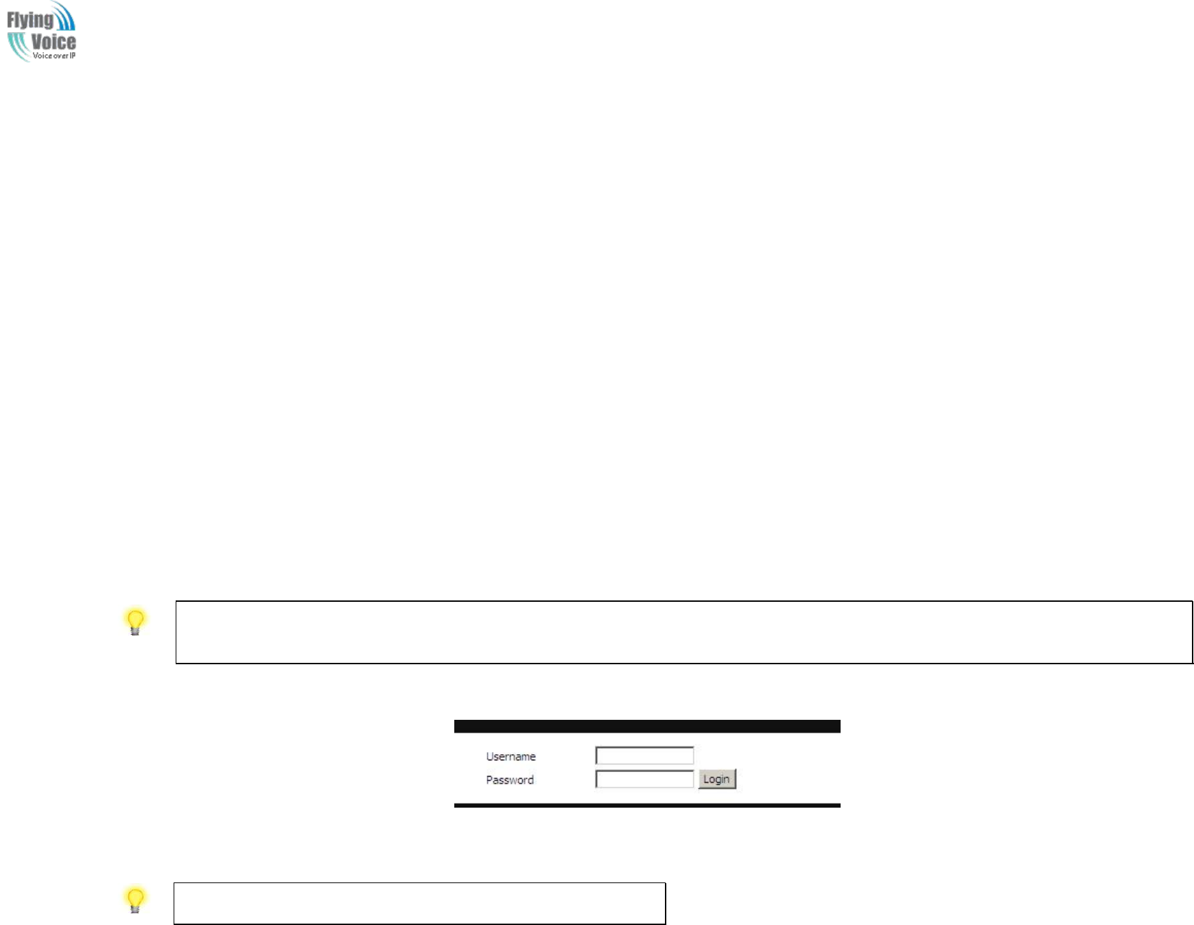
FWR9202
FWR9202 supports
supports two-level
two-level management:
management: administrator
administrator and
and user.
user. For
For administrator
administrator mode
mode operation,
operation, please
please type
type “
“admin/admin
admin/admin”
”on
on
Username/Password
Username/Password and
and click
click Login
Login button
button to
to configuration.
configuration. W
While
hile f
for
or user
user mode
mode operation,
operation, please
please type
type “
“user
user/
/user
user”
”on
on Username/Password
Username/Password
and
and click
click Login
Login button
button for
for full
full configuration.
configuration.
3.2 Accessing Web Page
3.2.1 From LAN port
1.
1. Make
Make sure
sure your
your PC
PC have
have connect
connected
ed to
to the
the router
router’
’s
sLAN
LAN port
port correctly.
correctly.
Notice: You may either simply set up your computer to get IP dynamically from the router or set up the IP address of the computer to be the same subnet as the default IP
address of router is 192.168.1.1. For the detailed information, please refer to the later section - Trouble shooting of the guide.
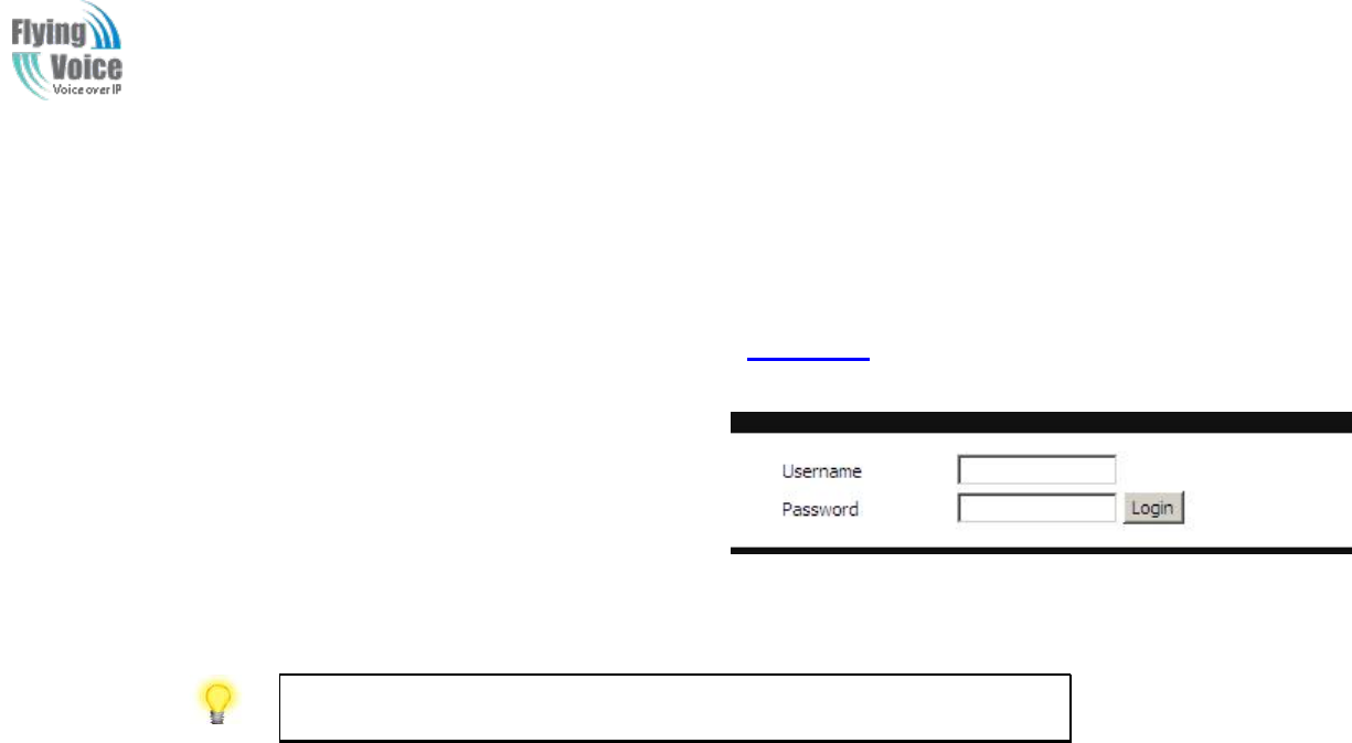
2.
2. Open
Open a
aweb
web browser
browser on
on your
your PC
PC and
and type
type http://192.168.
http://192.168.1
1.1.
.1. The
The following
following window
window will
will be
be open
open to
to ask
ask for
for username
username and
and password
password,and
,and you
you
can
can choose
choose language
language.
.
3.
3. For
For administrator
administrator mode
mode operation,
operation, please
please type
type “
“admin/admin
admin/admin”
”on
on Username/Password
Username/Password and
and click
click Login
Login to
to configuration.
configuration. Yet,
Yet, for
for root
root user
user
mode
mode operation,
operation, please
please type
type “
“user
user/
/user
user”
”on
on Username/Password
Username/Password and
and click
click Login
Login for
for full
full configuration.
configuration.
Notice: If you fail to access to the web configuration, please go to “Trouble
Shooting” for detecting and solving your problem.
4.
4. The
The web
web page
page can
can be
be logged
logged out
out after
after 5
5minutes
minutes without
without any
any operation.
operation.
Copy Right 2017 All Rights Reserved by FLYINGVOICE TECHNOLOG LIMITED
V1.0
The page 14 of 78
Revision time: 2017-06-16 15:00
3.2.2 From WAN port
1.
1. Make
Make sure
sure your
your PC
PC can
can connect
connect to
to the
the router
router’
’s
sWAN
WAN port
port correctly.
correctly.
2.
2. Get
Getting
ting the
the IP
IP addresses
addresses of
of WAN
WAN port
port using
using Voice
Voice prompt.
prompt.
3.
3. Open
Open a
aweb
web browser
browser on
on your
your PC
PC and
and type
type http://
http://the
the IP
IP address
address of
of WAN
WAN port
port.
.The
The following
following window
window will
will be
be open
open to
to ask
ask for
for username
username
and
and password.
password.
4.
4. For
For administrator
administrator mode
mode operation,
operation, please
please type
type “
“admin/admin
admin/admin”
”on
on Username/Password
Username/Password and
and click
click Login
Login to
to configuration.
configuration. Yet,
Yet, for
for root
root
user
user mode
mode operation,
operation, please
please type
type “
“user
user/
/user
user”
”on
on Username/Password
Username/Password and
and click
click Login
Login for
for full
full configuration.
configuration.
Notice: If you fail to access to the web configuration, please go to “Trouble
Shooting” for detecting and solving your problem.
5.
5. The
The web
web page
page can
can be
be logged
logged out
out after
after 5
5minutes
minutes without
without any
any operation.
operation.
Copy Right 2017 All Rights Reserved by FLYINGVOICE TECHNOLOG LIMITED
V1.0
The page 15 of 78
Revision time: 2017-06-16 15:00
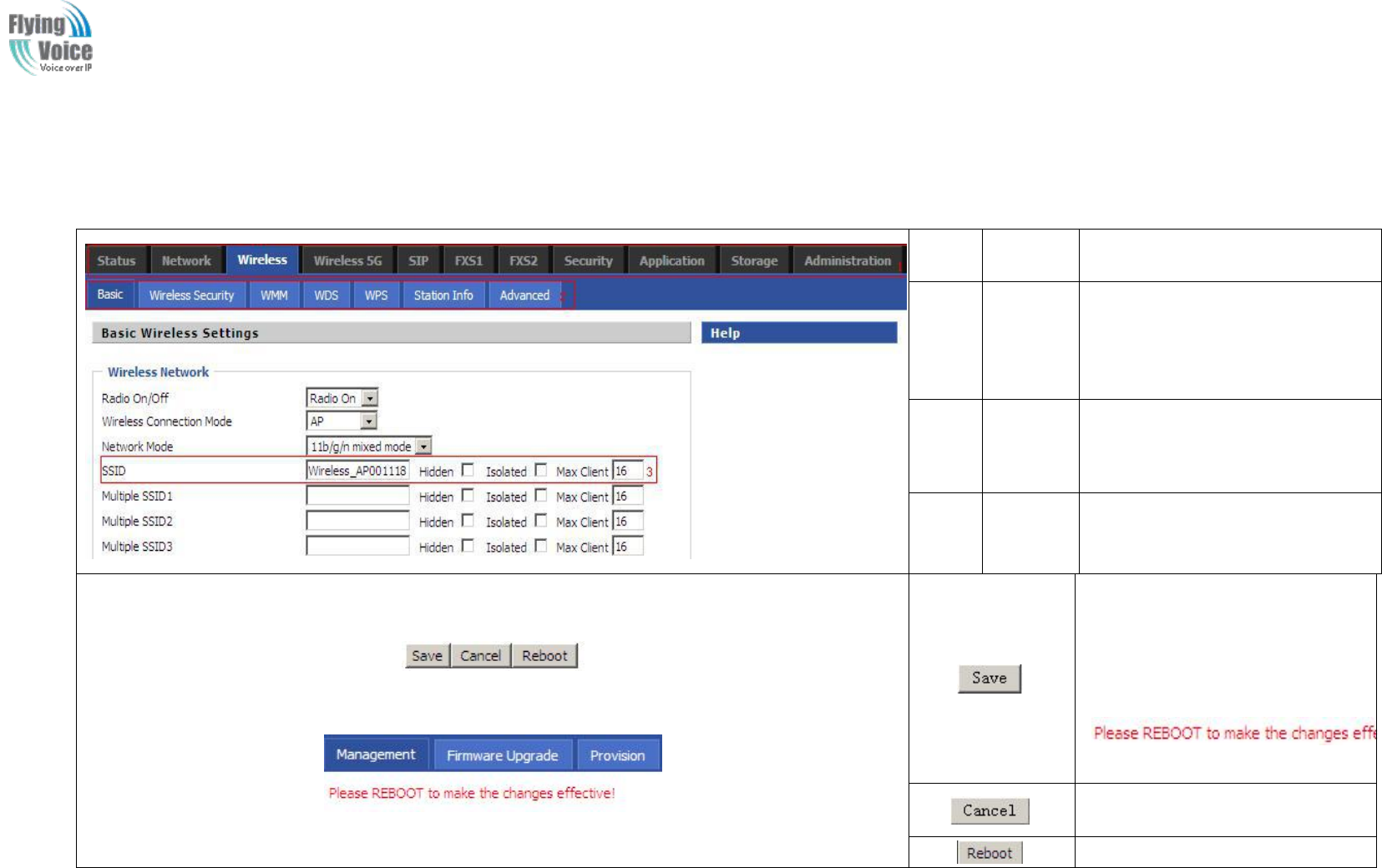
3.3 Web Page
NO.
Field
Name
Description
1
Navigati
on bar
Click navigation bar, many
sub-navigation bar will appear in
the place 2
2
Title
Click sub-navigation bar to
choose one configuration page
3
Paramet
er
To configuration the parameters
1.Every time making some
changes, user should press this
button to confirm the changes.
2.After pressing the button, the
red
will appear to notice rebooting.
To cancel the changes.
Press it to reboot the router
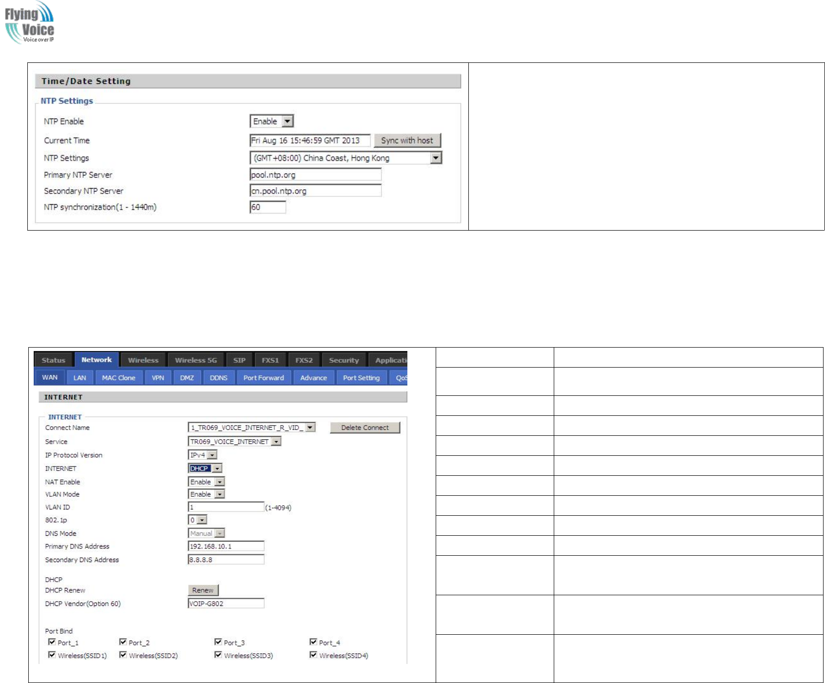
3.4 Setting up the Time Zone
Copy Right 2017 All Rights Reserved by FLYINGVOICE TECHNOLOG LIMITED
V1.0
The page 16 of 78
Revision time: 2017-06-16 15:00
Open Administration/Management webpage as shown left, please
select the Time Zone for the router installed and specify the NTP
server and set the update interval in NTP synchronization.
3.5 Setting up the Internet Connection
From
From WAN
WAN page,
page, multi
multi wan
wan connection
connection could
could be
be built
built or
or deteted.
deteted. If
If you
you want
want to
to know
know more
more information
information about
about Internet
Internet Connection
Connection setting,
setting, please
please
refer
refer to
to 5.3
5.3 section.
section.
Field Name
Description
Connect Name
Use keywords to indicate WAN port service model
Service
Chose the service mode.
IP Protocol Version
Only IPv4 for FWR9202
INTERNET
Choose Internet connection mode.
NAT Enable
If or not enable NAT.
VLAN Mode
If or not enable VLAN Mode.
VLAN ID
Set the VLAN ID.
802.1p
Set the priority of VLAN, Options are 0~7.
DNS Mode
The default is Manual.
Primary DNS
Address
The primary DNS of Internet port.
Secondary DNS
Address
The secondary DNS of Internet port.
Port Bind
Port bind is used for binding the service for different
LAN ports and SSIDs.
Copy Right 2017 All Rights Reserved by FLYINGVOICE TECHNOLOG LIMITED
V1.0
The page 17 of 78
Revision time: 2017-06-16 15:00
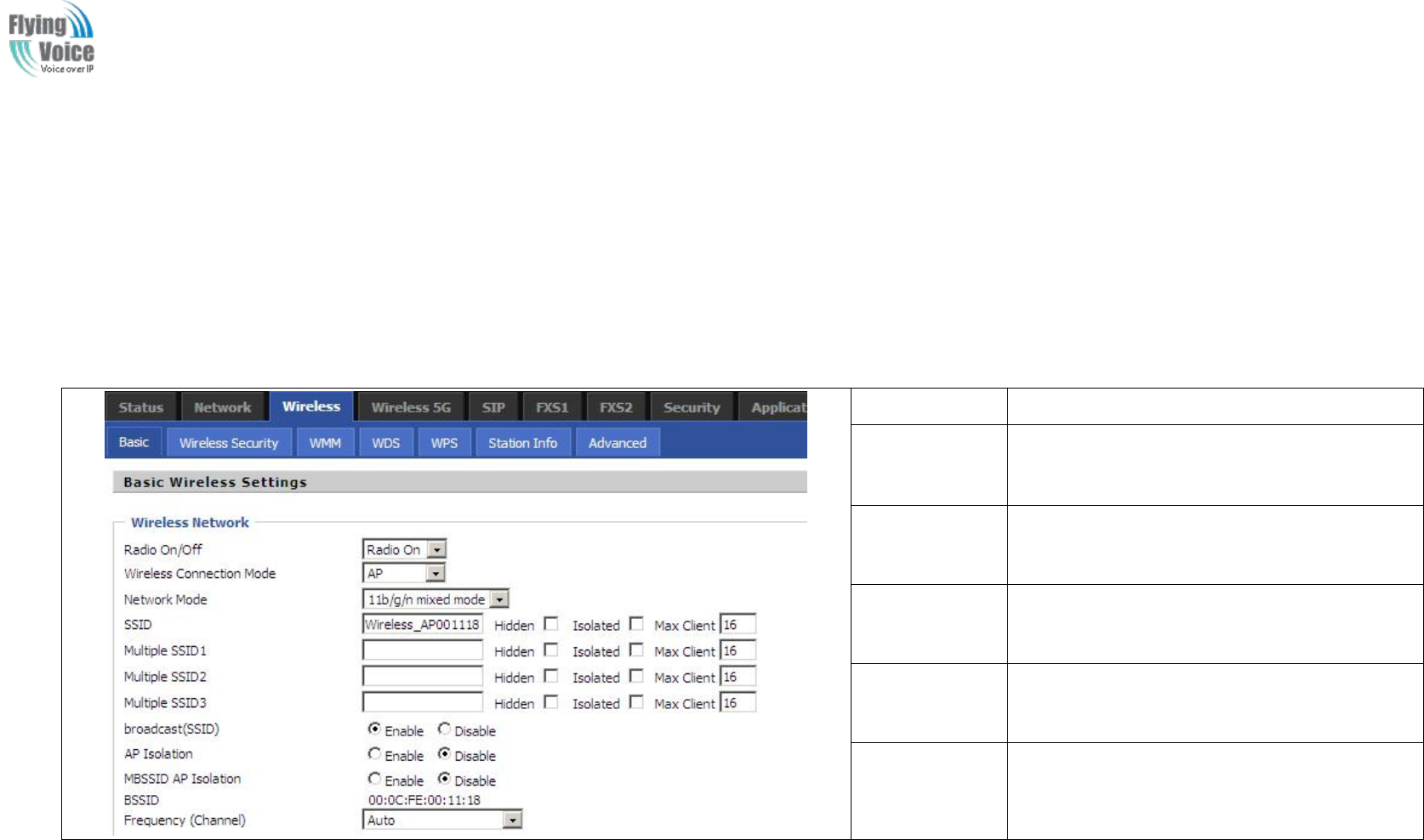
3.6 Setting up the Wireless Connection
To
To set
set up
up the
the wireless
wireless connection,
connection, please
please skip
skip the
the following
following step
steps
s.
.
3.6.1 Enable Wireless and Setting SSID
Open
Open Wireless/Basic
Wireless/Basic webpage
webpage as
as shown
shown below
below
Field Name
Description
Radio On/Off
Select “Radio Off” to disable wireless.
Select “Radio on”to enable wireless.
Network Mode
Choose one network mode from the drop
down list.
SSID
The name of the wireless name, it can be any
text numbers or various special characters.
Multiple
SSSD1-3
Set more wireless network.
Frequency
Choose channel frequency.
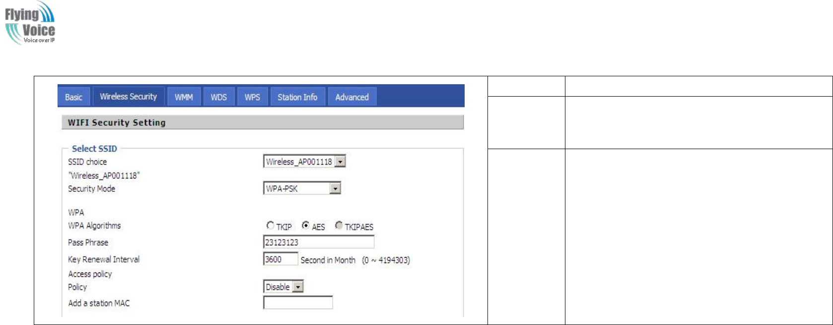
3.6.2 Encryption
Open
Open Wireless/Wireless
Wireless/Wireless Security
Security webpage
webpage to
to set
set the
the encryption
encryption of
of routers.
routers.
Copy Right 2017 All Rights Reserved by FLYINGVOICE TECHNOLOG LIMITED
V1.0
The page 18 of 78
Revision time: 2017-06-16 15:00
Field Name
Description
SSID Choice
Choose one SSID from Off-premises 1,
off-premises 2 and Premises.
Security
Mode
Select an appropriate encryption mode to improve
the security and privacy of your wireless data
packets.
Each encryption mode will bring out different web
page and ask you to offer additional configuration.
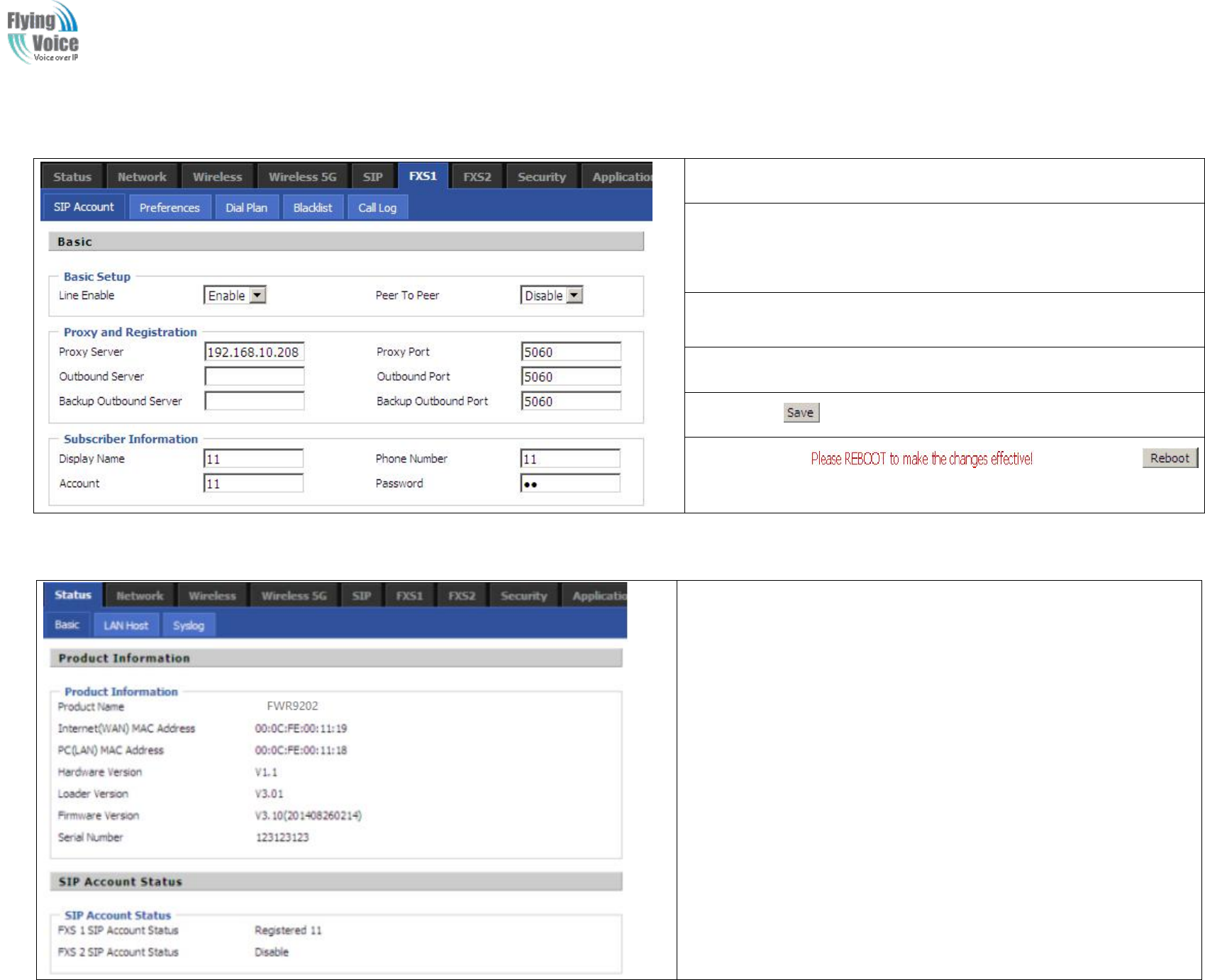
3.7 Register
3.7.1 Get the Accounts
FWR9202
FWR9202 have
have a
aFXS
FXS port,
port, you
you can
can use
use it
it to
to make
make SIP
SIP call,
call, and
and before
before registering,
registering, you
you should
should get
get the
the SIP
SIP account
account from
from you
you administrator
administrator or
or
provider
provider.
.
3.7.2 Connections
Connect
Connect FWR9202
FWR9202 to
to the
the Internet
Internet properly
properly
Copy Right 2017 All Rights Reserved by FLYINGVOICE TECHNOLOG LIMITED
V1.0
The page 19 of 78
Revision time: 2017-06-16 15:00
3.7.3 Configuration SIP from Webpage
Step
Step 1.Open
1.Open FXS1(FXS2)/
FXS1(FXS2)/SIP
SIP Account
Account webpage,
webpage, as
as the
the picture
picture in
in the
the
right
right side.
side.
Step
Step 2.Fill
2.Fill the
the SIP
SIP Server
Server domain
domain and
and SIP
SIP Server
Server address
address (which
(which get
get from
from
you
you administrator
administrator or
or provider)
provider) into
into Domain
Domain Name
Name parameter,
parameter, into
into SIP
SIP
Server
Server
Step
Step 3.Fill
3.Fill account
account which
which get
get from
from you
you administrator
administrator into
into Display
Display Name
Name
parameter,
parameter, Phone
Phone Number
Number parameter,
parameter, and
and Account
Account parameter.
parameter.
Step
Step 4.Fill
4.Fill password
password which
which get
get from
from you
you administrator
administrator into
into Password
Password
parameter.
parameter.
Step
Step 5.Press
5.Press button
button in
in the
the bottom
bottom of
of the
the webpage
webpage to
to save
save changes.
changes.
Note:
Note: if
if there
there is
is ,
,please
please press
press
button
button to
to make
make changes
changes effective.
effective.
3.7.4 View the Register Status
To
To view
view the
the status,
status, please
please open
open Status
Status webpage
webpage and
and view
view the
the value
value of
of
register
register status.
status. The
The value
value is
is registered
registered like
like the
the following
following picture
picture which
which
means
means FWR9202
FWR9202 have
have registered
registered normally
normally and
and you
you can
can make
make calls.
calls.

Copy Right 2017 All Rights Reserved by FLYINGVOICE TECHNOLOG LIMITED
V1.0
The page 20 of 78
Revision time: 2017-06-16 15:00
3.8 Make Call
3.8.1 Calling phone or extension numbers
To
To make
make a
aphone
phone or
or extension
extension number
number call:
call:
1.
1. Both
Both ATA
ATA and
and the
the other
other VoIP
VoIP device
device (i.e.,
(i.e., another
another ATA
ATA or
or other
other SIP
SIP products)
products) have
have public
public IP
IP addresses,
addresses, or
or
2.
2. Both
Both ATA
ATA and
and the
the other
other VoIP
VoIP device
device (i.e.,
(i.e., another
another ATA
ATA or
or other
other SIP
SIP products)
products) are
are on
on the
the same
same LAN
LAN using
using private
private or
or public
public IP
IP addresses,
addresses, or
or
3.
3. Both
Both ATA
ATA and
and the
the other
other VoIP
VoIP device
device (i.e.,
(i.e., another
another ATA
ATA or
or other
other SIP
SIP products)
products) can
can be
be connected
connected through
through a
arouter
router using
using public
public or
or private
private IP
IP
addresses.
addresses.
To
To make
make a
acall,
call, first
first pick
pick up
up the
the analog
analog phone
phone or
or turn
turn on
on the
the speakerphone
speakerphone on
on the
the analog
analog phone,
phone, i
input
nput the
the IP
IP address
address directly,
directly, end
end with
with #.
#.
3.8.2 Direct IP calls
Direct
Direct IP
IP calling
calling allows
allows two
two phones,
phones, that
that is,
is, an
an ATA
ATA with
with an
an analog
analog phone
phone and
and another
another VoIP
VoIP Device,
Device, to
to talk
talk to
to each
each other
other without
without a
aSIP
SIP proxy.
proxy.
VoIP
VoIP calls
calls can
can be
be made
made between
between two
two phones
phones if:
if:
1.
1. Both
Both ATA
ATA and
and the
the other
other VoIP
VoIP device
device (i.e.,
(i.e., another
another ATA
ATA or
or other
other SIP
SIP products)
products) have
have public
public IP
IP addresses,
addresses, or
or
2.
2. Both
Both ATA
ATA and
and the
the other
other VoIP
VoIP device
device (i.e.,
(i.e., another
another ATA
ATA or
or other
other SIP
SIP products)
products) are
are on
on the
the same
same LAN
LAN using
using private
private or
or public
public IP
IP addresses,
addresses, or
or
3.
3. Both
Both ATA
ATA and
and the
the other
other VoIP
VoIP device
device (i.e.,
(i.e., another
another ATA
ATA or
or other
other SIP
SIP products)
products) can
can be
be connected
connected through
through a
arouter
router using
using public
public or
or private
private IP
IP
addresses.
addresses.
To
To make
make a
adirect
direct IP
IP call,
call, first
first pick
pick up
up the
the analog
analog phone
phone or
or turn
turn on
on the
the speakerphone
speakerphone on
on the
the analog
analog phone,
phone, Input
Input the
the IP
IP address
address directly,
directly, with
with the
the
end
end “
“#
#”
”.
.
3.8.3 Call Hold
While
While in
in conversation,
conversation, press
pressing
ing the
the “
“*77
*77”
”to
to put
put the
the remote
remote end
end on
on hold
hold,
,then
then you
you will
will hear
hear the
the dial
dial tone
tone and
and the
the remote
remote party
party will
will hear
hear hold
hold tone
tone
at
at the
the same
same time.
time.
Pressing
Pressing the
the “
“*77
*77”
”again
again to
to release
release the
the previously
previously h
hold
old state
state and
and resume
resume the
the bi-directional
bi-directional media.
media.
3.8.4 Blind Transfer
Assuming
Assuming that
that call
call party
party A
Aand
and party
party B
Bare
are in
in conversation.
conversation. A
Awants
wants to
to Blind
Blind Transfer
Transfer B
Bto
to C:
C:
Step
Step 1.Party
1.Party A
Adials
dials “
“*78
*78”
”to
to get
get a
adial
dial tone,
tone, then
then dials
dials party
party C
C’
’s
snumber,
number, and
and then
then press
press immediately
immediately key
key #
#(or
(or wait
wait for
for 4
4seconds)
seconds) to
to dial
dial out.
out.
Step
Step 2.A
2.A can
can hang
hang up.
up.

Copy Right 2017 All Rights Reserved by FLYINGVOICE TECHNOLOG LIMITED
V1.0
The page 21 of 78
Revision time: 2017-06-16 15:00
3.8.5 Attended Transfer
Assuming
Assuming that
that call
call party
party A
Aand
and B
Bare
are in
in conversation.
conversation. A
Awants
wants to
to Attend
Attend Transfer
Transfer B
Bto
to C:
C:
Step
Step 1.Party
1.Party A
Adial
dial “
“*77
*77”
”to
to hold
hold the
the party
party B,
B, when
when hear
hear the
the dial
dial tone,
tone, A
Adial
dial C
C’
’s
snumber,
number, then
then party
party A
Aand
and party
party C
Care
are in
in convers
conversat
ation.
ion.
Step
Step 2.Party
2.Party A
Adial
dial “
“*78
*78”
”to
to transfer
transfer to
to C,
C, then
then B
Band
and C
Cnow
now in
in conversation.
conversation.
Step
Step 3.If
3.If the
the transfer
transfer doesn
doesn’
’t
tsuccess,
success, then
then A
Aand
and B
Bin
in conversation
conversation again.
again.
3.8.6 Conference
Assuming
Assuming that
that call
call party
party A
Aand
and B
Bare
are in
in conversation.
conversation. A
Awants
wants to
to add
add C
Cto
to the
the conference
conference:
:
Step
Step 1.Party
1.Party A
Adial
dial “
“*77
*77”
”to
to hold
hold the
the party
party B,
B, when
when hear
hear the
the dial
dial tone,
tone, A
Adial
dial C
C’
’s
snumber,
number, then
then party
party A
Aand
and party
party C
Care
are in
in convers
conversat
ation.
ion.
Step
Step 2.Party
2.Party A
Adial
dial “
“*
*88
88”
”to
to add
add C,
C, then
then A,
A, B
Band
and C
Cnow
now in
in conference
conference.
.
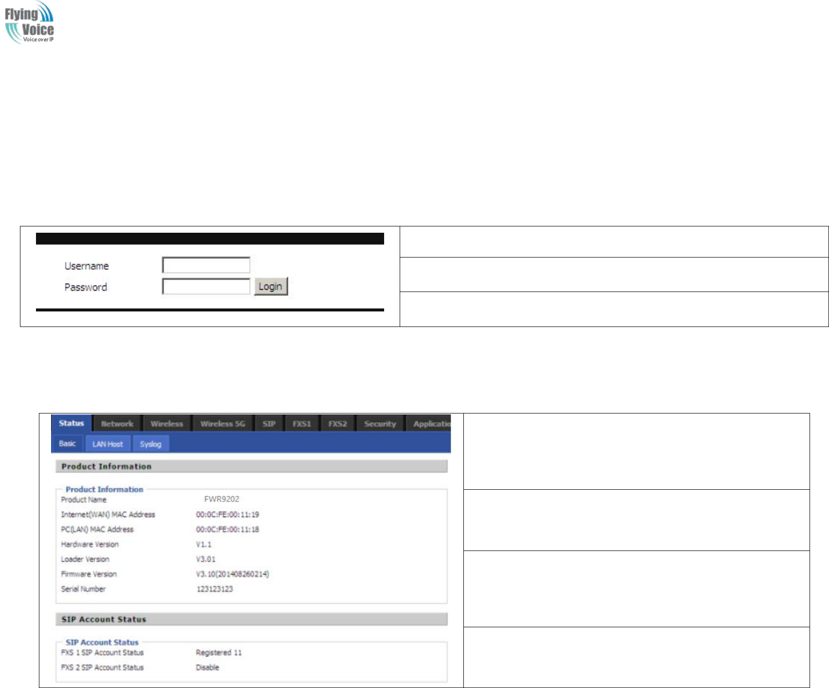
Copy Right 2017 All Rights Reserved by FLYINGVOICE TECHNOLOG LIMITED
V1.0
The page 22 of 78
Revision time: 2017-06-16 15:00
4Web Configuration
This
This chapter
chapter will
will guide
guide users
users to
to execute
execute advanced
advanced (full)
(full) configuration
configuration through
through admin
admin mode
mode operation.
operation.
4.1 Login
Step
Step 1.Connect
1.Connect the
the LAN
LAN port
port of
of the
the router
router to
to your
your PC
PC
Step
Step 2.Open
2.Open a
aweb
web browser
browser on
on your
your PC
PC and
and type
type in
in http://192.168.1.1
http://192.168.1.1.
.The
The window
window will
will
ask
ask for
for typing
typing username
username and
and password.
password. And
And you
you can
can choose
choose language,
language, too.
too.
Step
Step 3.Please
3.Please type
type “
“admin/admin
admin/admin”
”on
on Username/Password
Username/Password for
for administration
administration
operation.
operation.
4.2 Status
This
This webpage
webpage shows
shows the
the status
status information
information about
about product
product
information,
information, Network
Network and
and system
system.
.
It
It shows
shows the
the basic
basic information
information of
of the
the product,
product, such
such as
as product
product name,
name,
serial
serial number,
number, MAC
MAC address,
address, hardware
hardware version
version and
and software
software version
version
It
It also
also shows
shows the
the information
information of
of Link
Link Status,
Status, WAN
WAN Port
Port Status,
Status, and
and
LAN
LAN Port
Port Status.
Status.
And
And it
it shows
shows the
the current
current time
time and
and the
the running
running time
time of
of the
the product.
product.
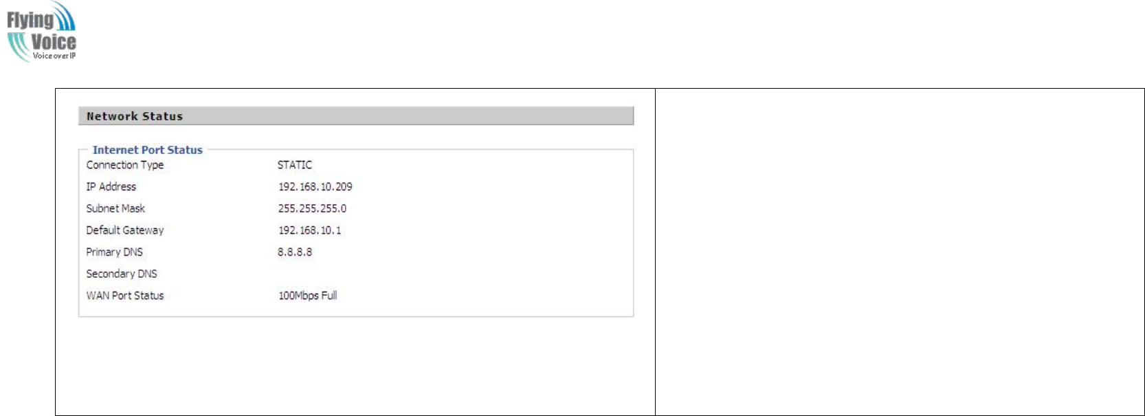
Copy Right 2017 All Rights Reserved by FLYINGVOICE TECHNOLOG LIMITED
V1.0
The page 23 of 78
Revision time: 2017-06-16 15:00
The
The picture
picture in
in the
the left
left side
side is
is the
the FWR9202
FWR9202’
’s
sStatus
Status webpage.
webpage.
4.3 Network&Security
You
You can
can configuration
configuration the
the WAN
WAN port,
port, LAN
LAN port,
port, DDNS,
DDNS, Multi
Multi WAN,DMZ,
WAN,DMZ, MAC
MAC Clone,
Clone, Port
Port Forward
Forward and
and so
so on
on in
in these
these two
two bars.
bars.
4.3.1 WAN
This
This page
page allows
allows you
you to
to set
set WAN
WAN configuration
configuration with
with different
different modes.
modes. Use
Use the
the Connection
Connection Type
Type drop
drop down
down list
list to
to choose
choose one
one WAN
WAN mode
mode and
and
then
then the
the cor
corresponding
responding page
page will
will be
be displayed.
displayed.
1.
1. Static
Static IP
IP
You
You will
will receive
receive a
afixed
fixed public
public IP
IP address
address or
or a
apublic
public subnet,
subnet, namely
namely multiple
multiple public
public IP
IP addresses
addresses from
from your
your DSL
DSL or
or Cable
Cable ISP
ISP service
service providers.
providers.
In
In most
most cases,
cases, a
aCable
Cable service
service provider
provider will
will offer
offer a
afixed
fixed public
public IP,
IP, while
while a
aDSL
DSL service
service provider
provider will
will offer
offer a
apublic
public subnet.
subnet. If
If you
you have
have a
apublic
public
subnet,
subnet, you
you could
could assign
assign an
an IP
IP address
address to
to the
the WAN
WAN interface.
interface.
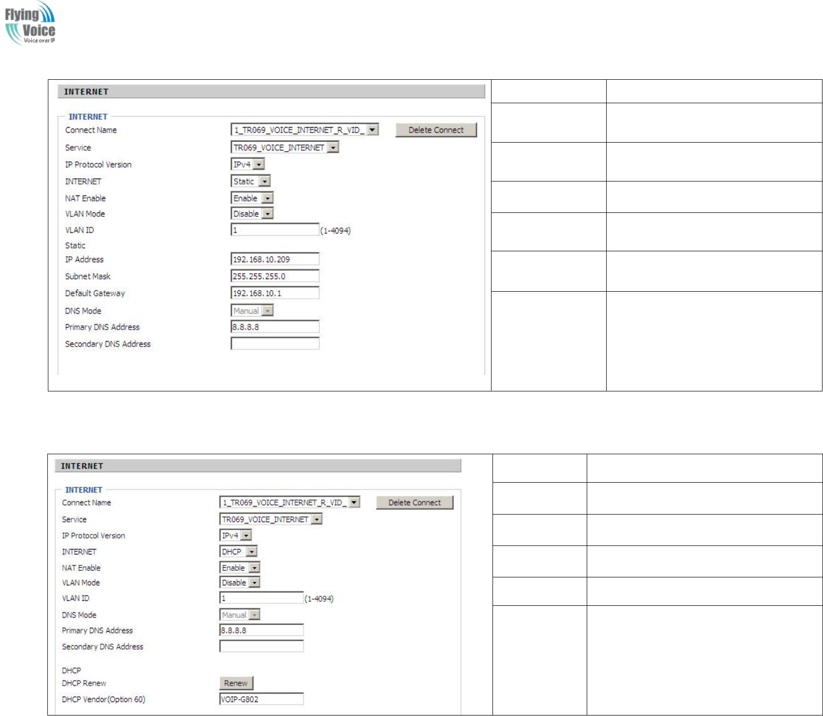
Copy Right 2017 All Rights Reserved by FLYINGVOICE TECHNOLOG LIMITED
V1.0
The page 24 of 78
Revision time: 2017-06-16 15:00
Field Name
Description
IP Address
The IP address of Internet port
Subnet Mask
The subnet mask of Internet port.
Default Gateway
The default gateway of Internet port.
DNS Mode
In Static mode, user need set the DNS
manually.
Primary DNS
Address
The primary DNS of Internet port.
Secondary DNS
Address
The secondary DNS of Internet port.
2.
2. DHCP
DHCP
It
It is
is not
not necessary
necessary for
for you
you to
to type
type any
any IP
IP address
address manually.
manually. Simply
Simply choose
choose this
this type
type and
and the
the system
system will
will obtain
obtain the
the IP
IP address
address automatically
automatically from
from
DHCP
DHCP server.
server.
Field Name
Description
DNS Mode
The Default is Manual
Primary DNS
Address
The primary DNS of Internet port.
Secondary DNS
Address
The secondary DNS of Internet port.
DHCP Renew
Refresh DHCP IP
DHCP
Vendor(Option6
0)
Specify DHCP Vendor field
Display the vendor and product name
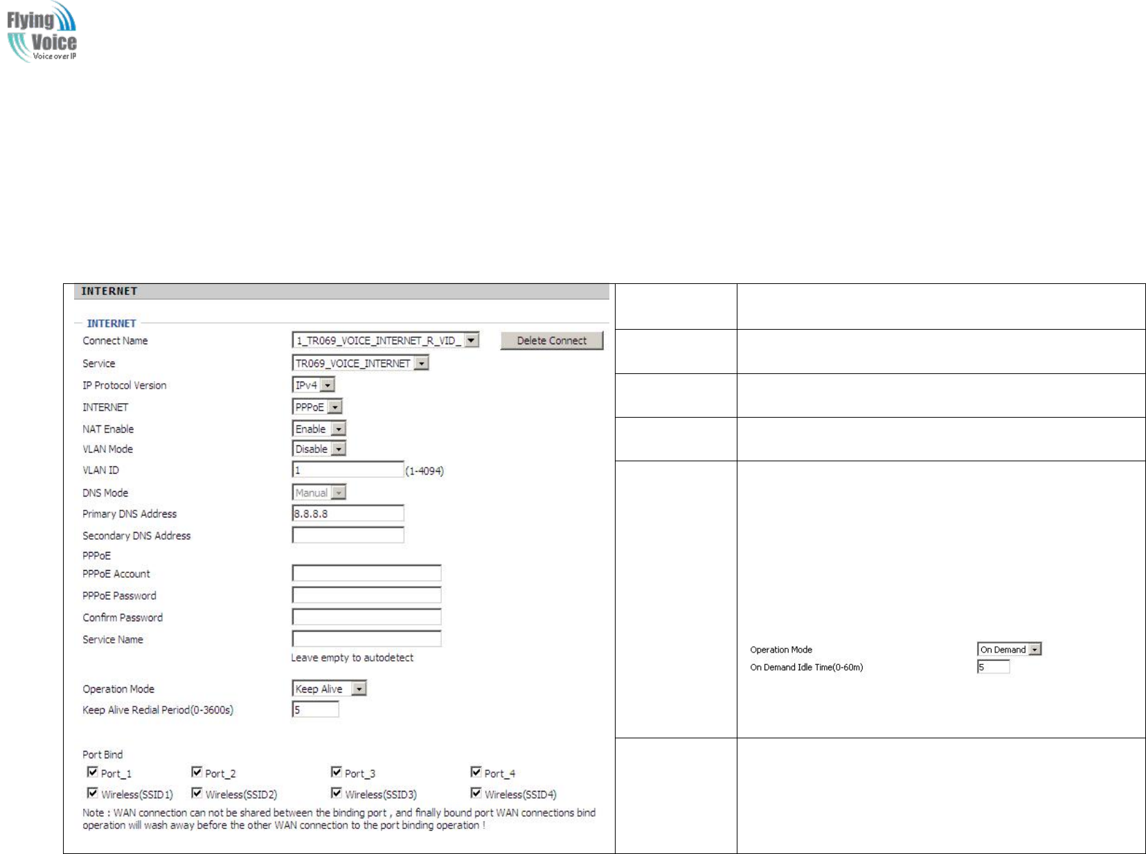
Copy Right 2017 All Rights Reserved by FLYINGVOICE TECHNOLOG LIMITED
V1.0
The page 25 of 78
Revision time: 2017-06-16 15:00
3.
3. PPPoE
PPPoE
PPPoE
PPPoE stands
stands for
for Point-to-Point
Point-to-Point Protocol
Protocol over
over Ethernet
Ethernet.
.It
It relies
relies on
on two
two widely
widely accepted
accepted standards:
standards: PPP
PPP and
and Ethernet.
Ethernet. It
It connects
connects users
users
through
through an
an Ethernet
Ethernet to
to the
the Internet
Internet with
with a
acommon
common broadband
broadband medium,
medium, such
such as
as a
asingle
single DSL
DSL line,
line, wireless
wireless device
device or
or cable
cable modem.
modem. All
All the
the users
users
over
over the
the Ethernet
Ethernet can
can share
share a
acommon
common connection.
connection.
PPPoE
PPPoE is
is used
used for
for most
most of
of DSL
DSL modem
modem users.
users. All
All local
local users
users can
can share
share one
one PPPoE
PPPoE connection
connection for
for accessing
accessing the
the Internet.
Internet. Your
Your service
service provider
provider
will
will provide
provide you
you information
information about
about user
user name,
name, password,
password, and
and authentication
authentication mode.
mode.
Field Name
Description
PPPoE
Account
Assign a valid user name provided by the ISP
PPPoE
Password
Assign a valid password provided by the ISP
Confirm
Password
Enter your PPPoE password again
Operation
Mode
Select the mode of operation, options are Keep Alive, On
Demand and Manual:
1.When the mode is Keep Alive, user need to set the 'keep
alive redial period' values range from 0 to 3600s, the
default setting is 5 minutes;
2. When the mode is On Demand, user need to set the 'on
demand idle time' value in the range of 0-60 minutes, the
default setting is 5 minutes;
♦
3.When the mode is Manual, no need to do other settings.
Keep Alive
Redial
Period
Set the interval to send Keep Alive
4.
4. Bridge
Bridge Mode
Mode
Bridge
Bridge Mode
Mode under
under Multi
Multi WAN
WAN is
is different
different with
with traditional
traditional bridge
bridge setting.
setting. Bridge
Bridge mode
mode has
has no
no ip
ip address
address and
and only
only work
work as
as a
abridge
bridge between
between WAN
WAN
port
port and
and LAN
LAN port.
port. So
So Route
Route Connection
Connection has
has to
to be
be build
build to
to give
give ip
ip address
address to
to local
local service
service on
on device.
device.
Under
Under is
is example
example of
of bridge
bridge mode:
mode:
1_TR069_VOICE_INTERNET_R_VID_
1_TR069_VOICE_INTERNET_R_VID_ is
is router
router connection
connection for
for local
local service.
service.
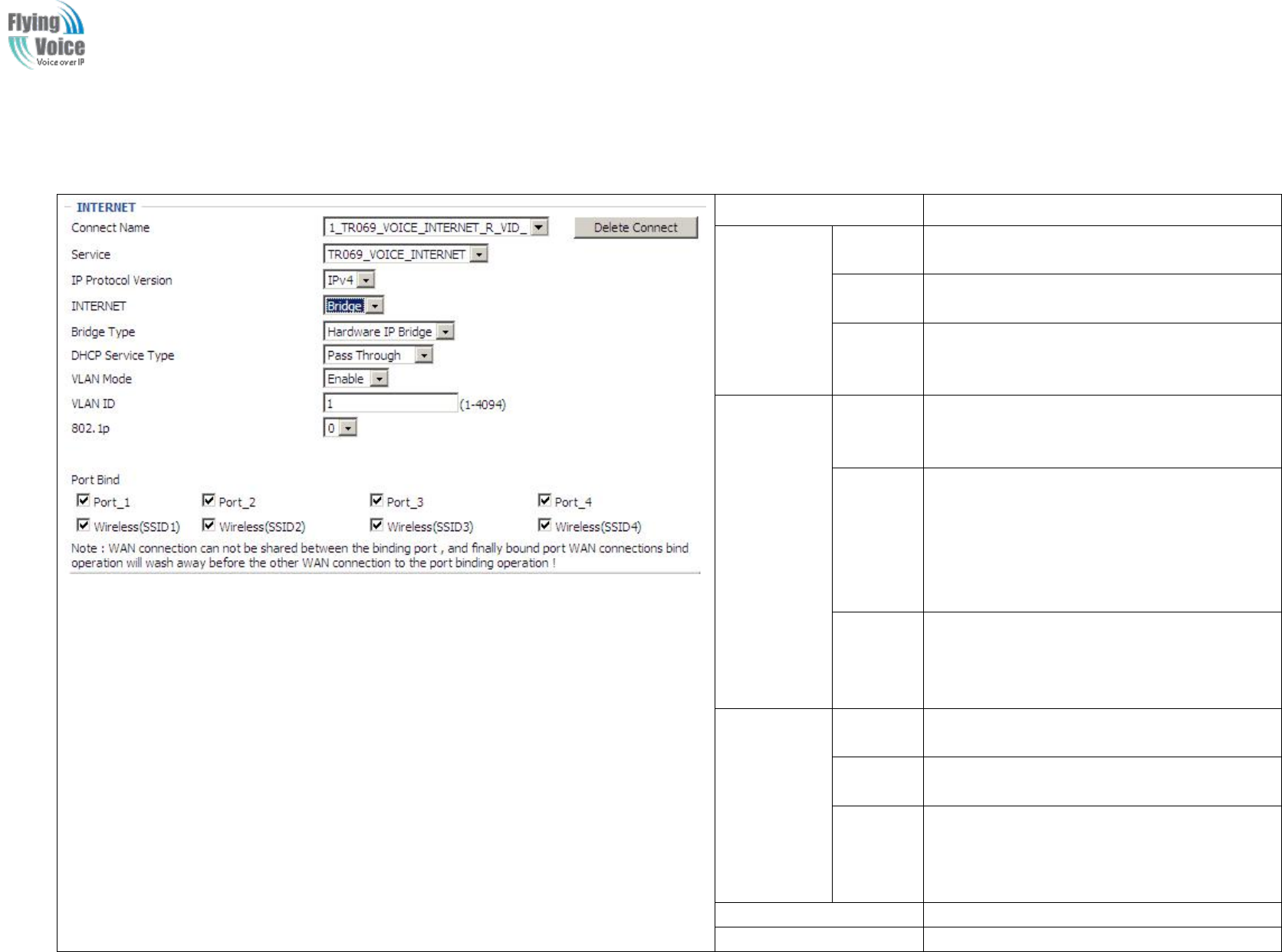
Copy Right 2017 All Rights Reserved by FLYINGVOICE TECHNOLOG LIMITED
V1.0
The page 26 of 78
Revision time: 2017-06-16 15:00
2_Other_B_VID_
2_Other_B_VID_ is
is bridge
bridge connection
connection for
for host
host of
of LAN
LAN port.
port.
If
If bridge
bridge setting
setting is
is complex,
complex, please
please refer
refer to
to 6.4
6.4 section
section for
for fast
fast setting
setting of
of bridge
bridge mode.
mode.
Field Name
Description
Bridge
Type
IP Bridge
Allow all ethernet packets pass. PC could
connect to upper network directly.
PPPoE
Bridge
Only Allow PPPoE packets pass. PC need
PPPoE dial-up software.
Hardware
IP Bridge
Packets pass through hardware switch with
wired speed. Do not support wireless port
bind.
DHCP
Service
Type
Pass
Through
Dhcp packets can be forwarded between
WAN and LAN, dhcp server in gateway will
not allocate IP to hosts of LAN port.
DHCP
Snooping
When gateway forwards dhcp packets form
LAN to WAN it will add option82 to dhcp
packet, and it will remove option82 when
forward dhcp packet form WAN to LAN.
Local dhcp service will not allocate ip to
hosts of LAN port.
Local
Service
Gateway will not forward dhcp packets
between Lan and Wan, it also block dhcp
packet from WAN port. Hosts of LAN port
can get ip from dhcp server run in gateway.
VLAN
Mode
Disable
The WAN interface is untagged. LAN is
untagged.
Enable
The WAN interface is tagged. LAN is
untagged.
Trunk
Only valid in bridge mode. All ports, include
WAN and LAN, belong to this VLAN Id and
all ports are tagged in this VLAN id. Tagged
packets could pass through WAN and LAN.
VLAN
VLAN ID
ID
Set the VLAN ID.
802.1p
Set the priority of VLAN, Options are 0~7.

Copy Right 2017 All Rights Reserved by FLYINGVOICE TECHNOLOG LIMITED
V1.0
The page 27 of 78
Revision time: 2017-06-16 15:00
5.
5. Connect
Connect Name
Name and
and Service
Service
Connect
Connect Name
Name Table
Table is
is as
as below:
below:
Content
Define
Comment
No
1~99
WAN Connection id
Service
TR069
The connection only support
management application, like TR069,
WEB, SNMP and Provision
INTERNET
The connection only support internet
service
TR069_INTERNET
The connection support management
and internet application
VOICE
The connection only support voice
application, like sip and rtp
TR069_VOICE
The connection support both
management and voice application
VOICE_INTERNET
The connection support voice and
internet application
TR069_VOICE_INTERNET
The connection support management,
voice and internet application
Other
The connection support STB
NAT Mode
B
Bridge
R
Router
VLAN ID
VID
VLAN ID
For
For example:
example:
1.
1. 1_TR069_R_
1_TR069_R_VID_2
VID_2 (First
(First Interface,
Interface, Service
Service is
is TR069,
TR069, NAT
NAT Mode,
Mode, VLAN
VLAN ID
ID is
is 2)
2)
2.
2. 2_INTERNET_
2_INTERNET_B
B_
_VID_(Second
VID_(Second Interface,
Interface, Service
Service is
is INTERNET
INTERNET,
,Bridge
Bridge Mode,
Mode, VLAN
VLAN is
is disabled)
disabled)
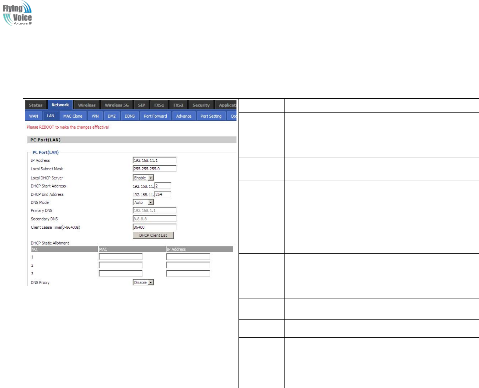
Copy Right 2017 All Rights Reserved by FLYINGVOICE TECHNOLOG LIMITED
V1.0
The page 28 of 78
Revision time: 2017-06-16 15:00
4.3.2 LAN
1.
1. LAN
LAN Port:
Port:
The
The most
most generic
generic function
function of
of router
router is
is NAT
NAT.
.What
What NAT
NAT does
does is
is to
to translate
translate the
the packets
packets from
from public
public IP
IP address
address to
to local
local IP
IP address
address to
to forward
forward the
the
right
right packets
packets to
to the
the right
right host
host and
and vice
vice versa.
versa.
Field Name
Description
IP Address
Enter the IP address of the router on the local area network, all the
IP addresses of the computers which are in the router’s LAN must
be in the same network segment with this address, and the default
gateway of the computers must be this IP address. (The default is
192.168.1.1)
Local Subnet
Mask
Enter the subnet mask to determine the size of the network (default
is 255.255.255.0/24)
Local DHCP
Server
If or not enable Local DHCP Server
DHCP Start
Address
Enter a valid IP address as a starting IP address of the DHCP server,
and if the router’s LAN IP address is 192.168.1.1, starting IP
address can be 192.168.1.2 or greater, but should be less than the
ending IP address.
DHCP End
Address
Enter a valid IP address as an end IP address of the DHCP server.
DNS Mode
Select DNS mode, options are Auto and Manual:
1. When DNS mode is Auto, the device under LAN port will
automatically obtains the preferred DNS and alternate DNS.
2. When DNS mode is Manual, the user should manually configure
the preferred DNS and alternate DNS
Primary
DNS
Enter the preferred DNS address.
Secondary
DNS
Enter the secondary DNS address.
Client Lease
Time
This option defines how long the address will be assigned to the
computer within the network. In that period, the server does not
assign the IP address to the other computer.
DNS Proxy
Enable or disable; If enabled, the device will forward the DNS
request of LAN-side network to the WAN side network
2.
2. DHCP
DHCP Server:
Server:
Router
Router has
has a
abuilt-in
built-in DHCP
DHCP server
server that
that assigns
assigns private
private IP
IP address
address to
to each
each local
local host.
host.
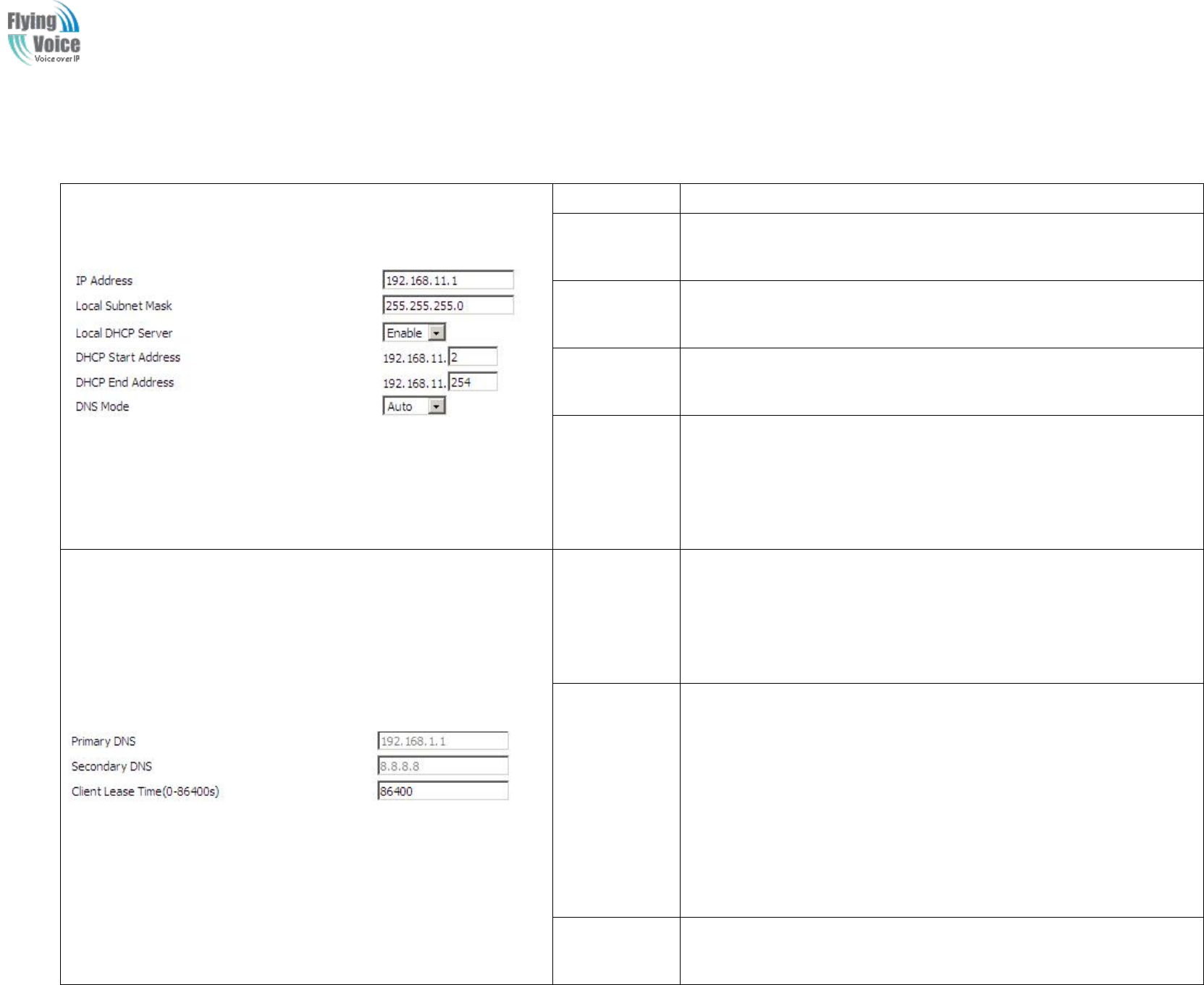
Copy Right 2017 All Rights Reserved by FLYINGVOICE TECHNOLOG LIMITED
V1.0
The page 29 of 78
Revision time: 2017-06-16 15:00
DHCP
DHCP stands
stands for
for Dynamic
Dynamic Host
Host Configuration
Configuration Protocol.
Protocol. The
The router
router by
by factory
factory default
default acts
acts a
aDHCP
DHCP server
server for
for your
your network
network so
so it
it automatically
automatically
dispatch
dispatch related
related IP
IP settings
settings to
to any
any local
local user
user configured
configured as
as a
aDHCP
DHCP client.
client. It
It is
is highly
highly recommended
recommended that
that you
you leave
leave the
the router
router enabled
enabled as
as a
a
DHCP
DHCP server
server if
if you
you do
do not
not have
have a
aDHCP
DHCP server
server for
for your
your network.
network.
Field Name
Description
Local DHCP
Server
If or not enable DHCP server.
DHCP Start
Address
Enter a value of the IP address pool for the DHCP server to start with
when issuing IP addresses. If the LAN Interface IP
DHCP End
Address
Enter a value of the IP address pool for the DHCP server to end with
when issuing IP addresses.
DNS Mode
You should set “manual” in the “DNS Mode” if you set “DNS” by
yourself. And then fill the DNS in the two following texts. Generally
speaking, you can set “Auto” in the “DNS Mode” and the device
will get “DNS” from DHCP Server automatically.
Primary DNS
You must specify a DNS server IP address here because your ISP
should provide you with usually more than one DNS Server. If your
ISP does not provide it, the router will automatically apply default
DNS Server IP address: 202.96.134.33 to this field.
Secondary
DNS
You must specify a DNS server IP address here because your ISP
should provide you with usually more than one DNS Server. If your
ISP does not provide it, the router will automatically apply default
DNS Server IP address: 202.96.128.86 to this field.
If both the Primary IP and Secondary IP Address fields are left empty,
the router will assign its own IP address to local users as a DNS proxy
server and maintain a DNS cache.
Client Lease
Time
It allows you to set the leased time for the specified PC.
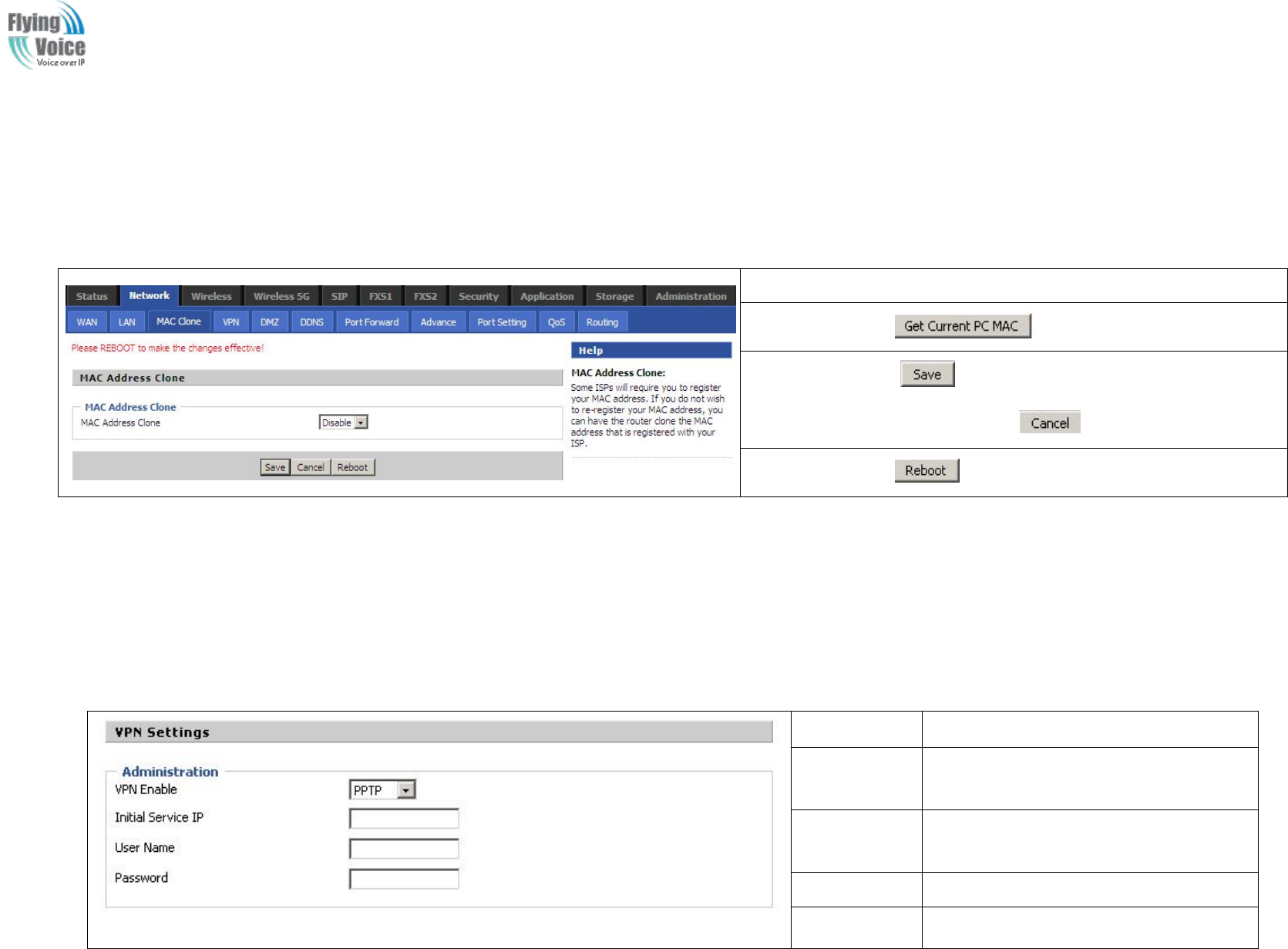
Copy Right 2017 All Rights Reserved by FLYINGVOICE TECHNOLOG LIMITED
V1.0
The page 30 of 78
Revision time: 2017-06-16 15:00
4.3.3 MAC Clone
Some
Some ISPs
ISPs will
will require
require you
you to
to register
register your
your MAC
MAC address.
address. If
If you
you do
do not
not wish
wish to
to re-register
re-register your
your MAC
MAC address,
address, you
you can
can have
have the
the router
router clone
clone the
the
MAC
MAC address
address that
that is
is registered
registered with
with your
your ISP.
ISP. To
To use
use the
the Clone
Clone Address
Address button,
button, the
the computer
computer viewing
viewing the
the Web-base
Web-base utility
utility screen
screen will
will have
have the
the
MAC
MAC address
address automatically
automatically entered
entered in
in the
the Clone
Clone WAN
WAN MAC
MAC field.
field.
Enabling MAC address cloning
1. Press the button gets PC's MAC address
2. Press the button to save your changes if users don't want to
use MAC clone, press the button to cancel the changes
3. Press the button to make the changes effective.
4.3.4 VPN
A
AVPN
VPN is
is a
akind
kind of
of technology
technology which
which establish
establish a
aprivate
private network
network based
based on
on the
the public
public network.
network. VPN
VPN network
network connection
connection between
between any
any two
two nodes
nodes
does
does not
not require
require the
the end
end to
to end
end physical
physical connection
connection as
as the
the traditional
traditional private
private network;
network; it
it is
is structure
structured
don
on the
the network
network platform
platform provided
provided by
by the
the
public
public network
network services,
services, the
the user
user d
dhome
home gateway
gateway are
are transmitted
transmitted in
in the
the logical
logical link.
link. Through
Through VPN
VPN technology,
technology, users
users can
can establish
establish connection
connection
between
between any
any two
two devices
devices which
which are
are connected
connected to
to public
public network
network and
and transmit
transmit dhome
dhome gateway.
gateway.
Field Name
Description
VPN Enable
If or not enable VPN.If enable, you can
select PPTP and L2TP mode VPN.
Initial Service
IP
Fill in the VPN server IP address
User Name
Fill in the authentication username
Password
Fill in the authentication password
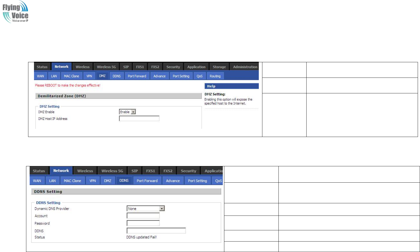
Copy Right 2017 All Rights Reserved by FLYINGVOICE TECHNOLOG LIMITED
V1.0
The page 31 of 78
Revision time: 2017-06-16 15:00
4.3.5 DMZ
Field Name
Description
DMZ Enable
If or not enable DMZ.
DMZ Host IP
Address
Enter the private IP address of the DMZ
host
4.3.6 DDNS Setting
Field Name
Description
Dynamic DNS
Provider
DDNS is enabled and select a DDNS service provider
Account
Enter the DDNS service account
Password
Enter the DDNS service account password
DDNS
Enter the DDNS domain name or IP address
Status
See if DDNS is successfully upgraded
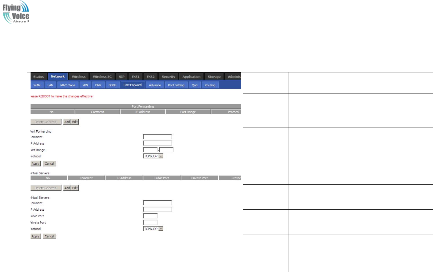
Copy Right 2017 All Rights Reserved by FLYINGVOICE TECHNOLOG LIMITED
V1.0
The page 32 of 78
Revision time: 2017-06-16 15:00
4.3.7 Port Forward
Field Name
Description
Comment
Sets the name of a port mapping rule or comment
IP Address
The IP address of devices under the LAN port.
Port Range
Set the port range for the devices under the LAN port.
(1-65535)
Protocol
You can select TCP, UDP, TCP & UDP three cases
Apply/Cancel
After finish configurations, click apply, the number
will be generated under NO. List; click Cancel to if
you do not want to make the changes.
Comment
To set up a virtual server notes
IP Address
Virtual server IP address
Public Port
Public port of virtual server
Private Port
Private port of virtual servers ports
Protocol
You can select from TCP, UDP, and TCP&UDP.
Apply/Cancel
After finish configurations, click apply, the number
will be generated under NO. List; click Cancel to if
you do not want to make the changes.
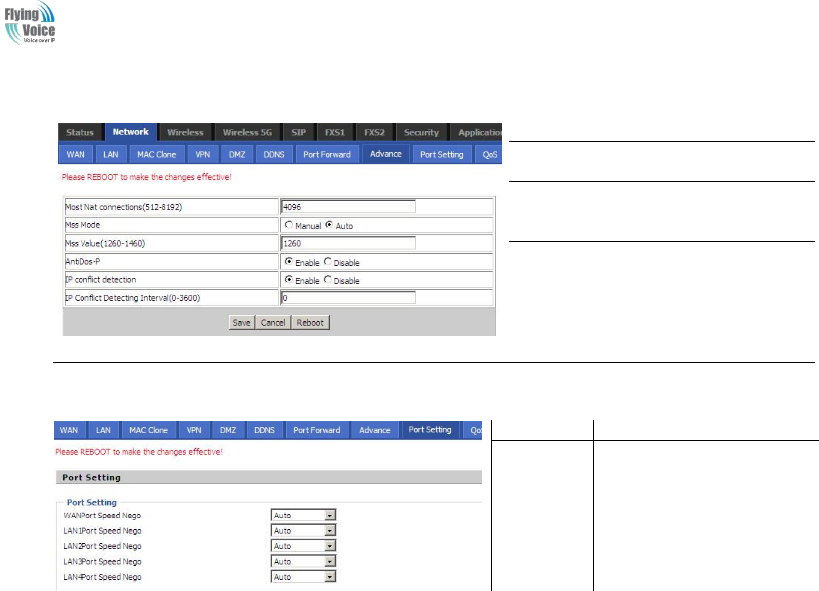
Copy Right 2017 All Rights Reserved by FLYINGVOICE TECHNOLOG LIMITED
V1.0
The page 33 of 78
Revision time: 2017-06-16 15:00
4.3.8 Advance
Field Name
Description
Most Nat
connections
The largest value which the FWR9202
can provide
Mss Mode
Choose Mss Mode from Manual and
Auto
Mss Value
Set the value of TCP
AntiDos-p
You can choose to enable or prohibit
IP conflict
detection
Select enable if enabled, phone IP
conflict will have tips or prohibit;
IP conflict
Detecting
Interval
Detect IP address conflicts of the time
interval
4.3.9 Port Setting
Field Name
Description
WAN Port Speed
Nego
Auto-negotiation, options are Auto, 100M
full, 100M half-duplex, 10M half and full,
select port speed negotiation supported by
methods.
LAN1~LAN4Port
Speed Nego
Auto-negotiation, options are Auto, 100M
full, 100M half, 10M half and 10M full,
select port speed negotiation methods.
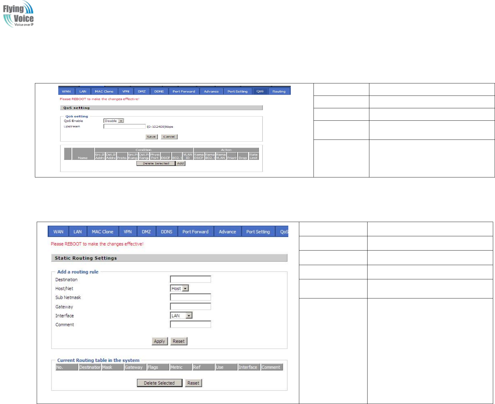
Copy Right 2017 All Rights Reserved by FLYINGVOICE TECHNOLOG LIMITED
V1.0
The page 34 of 78
Revision time: 2017-06-16 15:00
4.3.10 QoS
Field Name
Description
QoS Enable
If or not enable Qos function
Upstream
Set the upstream bandwidth
Delete Selected
In NO., Check the items you want to
delete, click the Delete option
Add
Click Add to add a new parameter
4.3.11 Routing
Field Name
Description
Destination
Destination address
Host/Net
Both Host and Net selection
Gateway
Gateway IP address
Interface
LAN/WAN/Custom three options, and
add the corresponding address
Comment
Comment
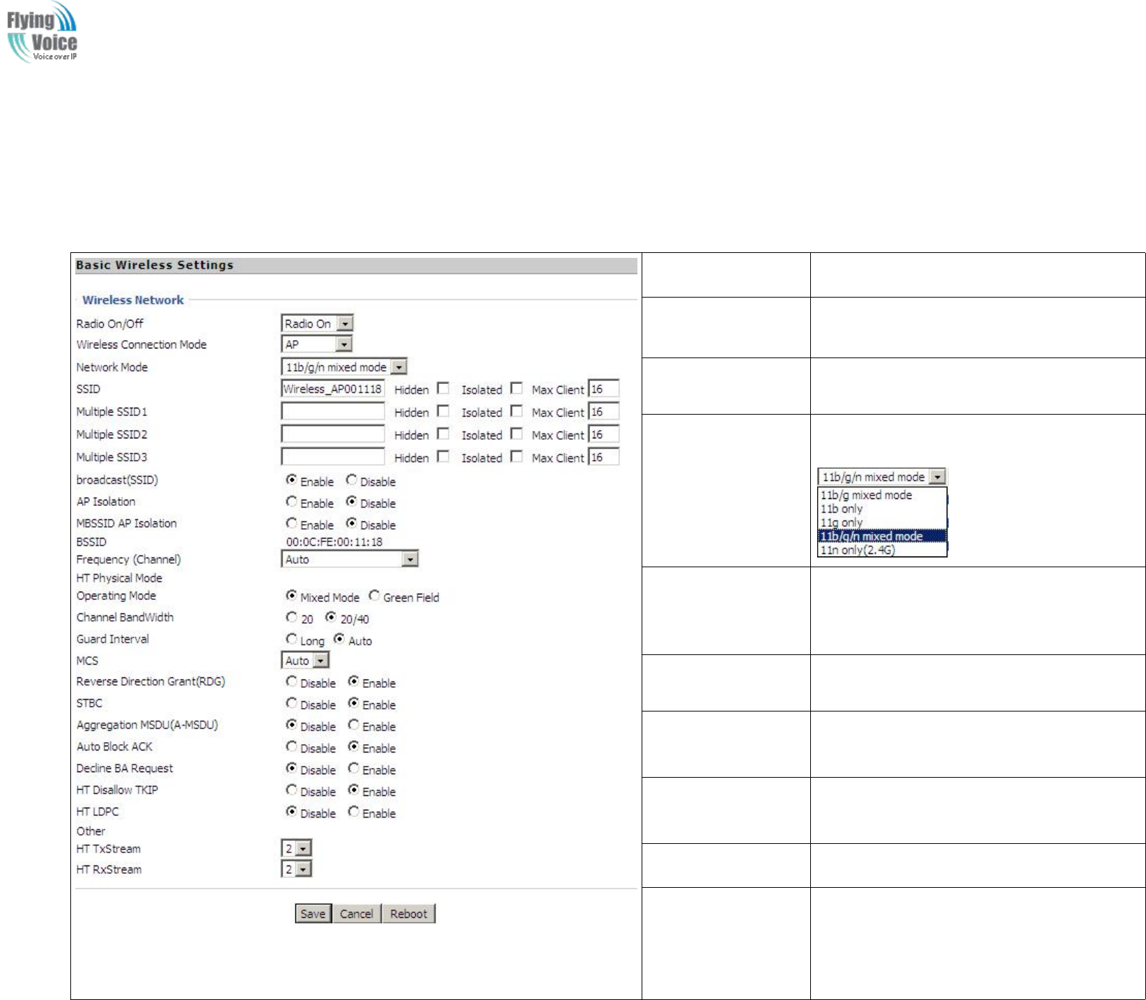
Copy Right 2017 All Rights Reserved by FLYINGVOICE TECHNOLOG LIMITED
V1.0
The page 35 of 78
Revision time: 2017-06-16 15:00
4.4 Wireless
4.4.1 Basic
Field Name
Description
Radio on/off
Select “Radio Off” to disable wireless.
Select “Radio on”to enable wireless.
Wireless connection
mode
According to the wireless client type, select
one of these modes. Default is AP
Network Mode
Choose one network mode from the drop down
list. Default is 11b/g/n mixed mode
SSID
It is the basic identity of wireless LAN. SSID
can be any alphanumeric or a combination of
special characters. It will appear in the wireless
network access list.
Multiple
SSID1~SSID3
FWR9202 supports multiple SSIDs.
Hidden
After the item is checked, the SSID is no
longer displayed in the search for the Wi-Fi
wireless network connection list
Broadcast(SSID)
After initial State opening, the device
broadcasts the SSID of the router to wireless
network
AP Isolation
If AP isolation is enabled, the clients of the AP
cannot access each other.
MBSSID AP
Isolation
AP isolation among the devices which are not
belong to this AP and along to, when the option
is enabled, the devices which do not belong to
this AP cannot access the devices which are

Copy Right 2017 All Rights Reserved by FLYINGVOICE TECHNOLOG LIMITED
V1.0
The page 36 of 78
Revision time: 2017-06-16 15:00
within the AP.
BSSID
A group of wireless stations and a WLAN
access point (AP) consists of a basic access
device (BSS), each computer in the BSS must
be configured with the same BSSID, that is, the
wireless AP logo.
Frequency (Channel)
You can select Auto Select and channel
1/2/3/4/5/6/7/8/9/10/11.
HT Physical Mode
Operating
Mode
1. Mixed Mode: In this mode, the previous
wireless card can recognize and connect to the
Pre-N AP, but the throughput will be affected
2. Green Field: high throughput can be
achieved, but it will affect backward
compatibility, and security of the system
Channel Bandwidth
Select channel bandwidth, default is 20MHz
and 20/40MHz.
Guard Interval
The default is automatic, in order to achieve
good BER performance, you must set the
appropriate guard interval
MCS
Position control signal, options are 0 to 32, the
default is automatic
Reverse Direction
(RDG)
You can choose to enable or disable this
privilege
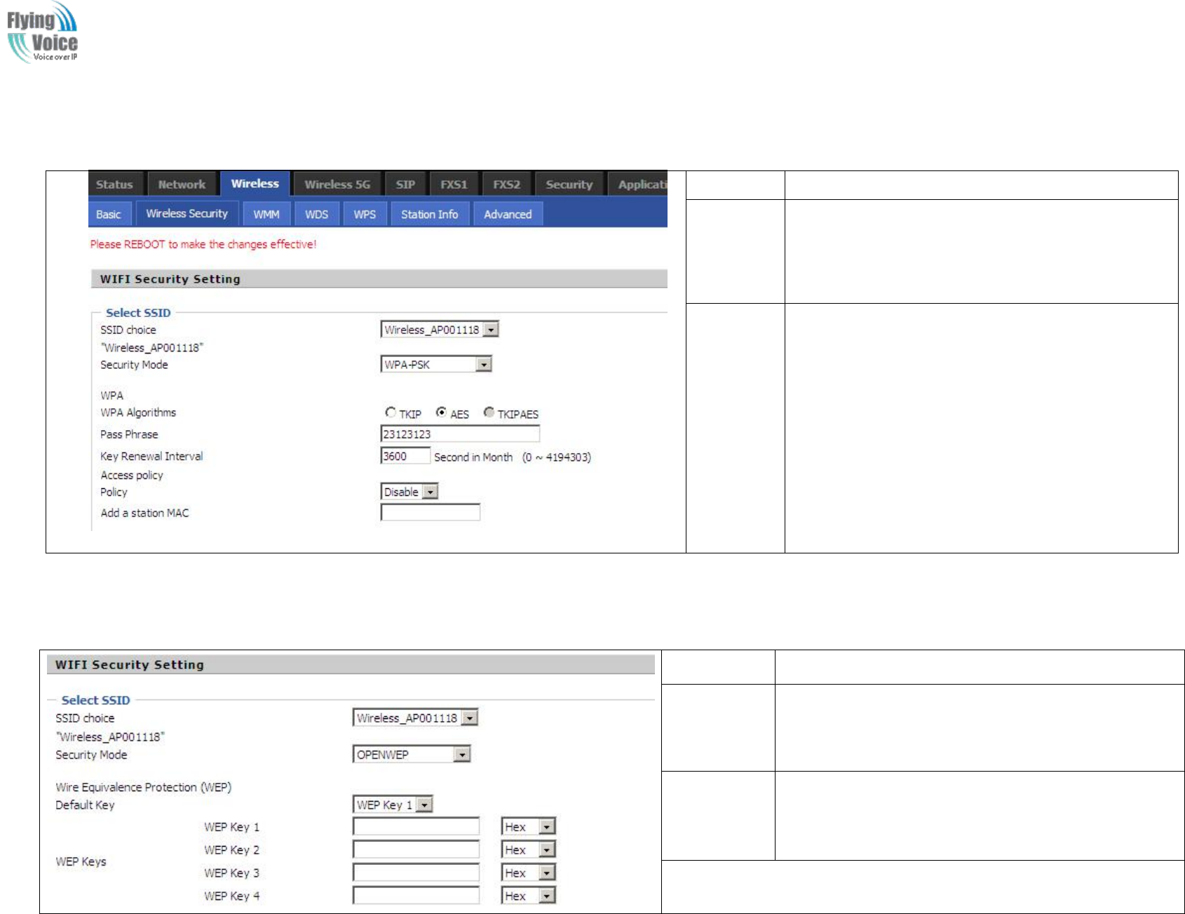
Copy Right 2017 All Rights Reserved by FLYINGVOICE TECHNOLOG LIMITED
V1.0
The page 37 of 78
Revision time: 2017-06-16 15:00
4.4.2 Wireless Security
Field Name
Description
SSID
Choice
Choose one SSID from SSID, Multiple SSID1,
Multiple SSID2 and Multiple SSID3.
Security
Mode
Select an appropriate encryption mode to improve
the security and privacy of your wireless data
packets.
Each encryption mode will bring out different web
page and ask you to offer additional configuration.
S
Select
elect a
adifferent
different encryption
encryption mode,
mode, the
the web
web interface
interface will
will be
be different,
different, user
user can
can configure
configure the
the corresponding
corresponding parameters
parameters under
under the
the mode
mode you
you
select.
select. Here
Here are
are some
some common
common encryption
encryption method:
method:
1.
1. OPENWEP
OPENWEP:
:A
Ahandshake
handshake way
way of
of WEP
WEP encryption,
encryption, encryption
encryption via
via the
the WEP
WEP key:
key:
Field Name
Description
Security Mode
This is used to select one of the 4 WEP keys, key settings on the
clients should be the same with this when connecting.
WEP Keys
Set the WEP key. A-64 key need 10 Hex characters or 5 ASCII
characters; choose A-128 key need 26 Hex characters or 13 ASCII
characters.
WEP represents Wired Equivalent Privacy, which is a basic encryption method.
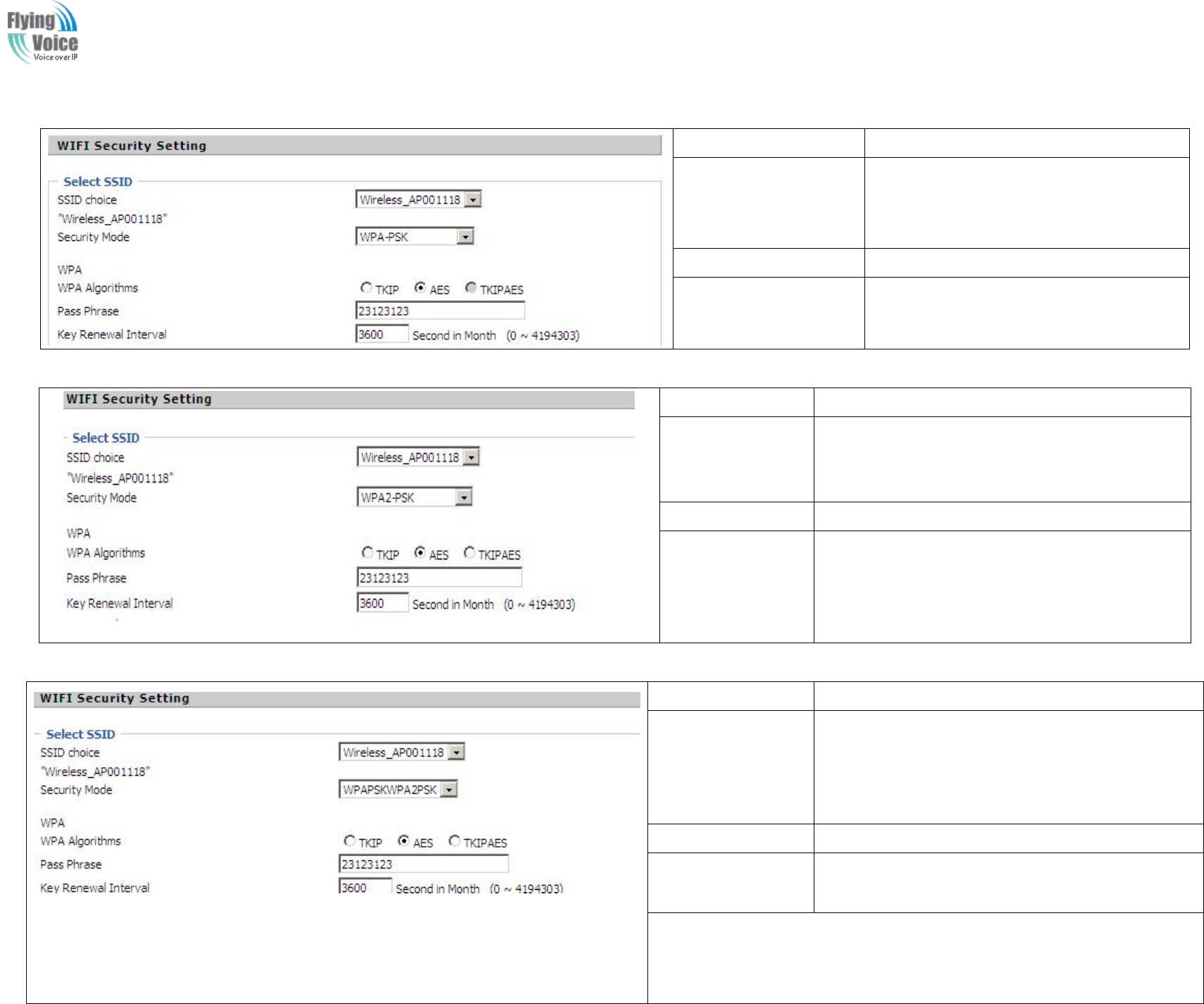
Copy Right 2017 All Rights Reserved by FLYINGVOICE TECHNOLOG LIMITED
V1.0
The page 38 of 78
Revision time: 2017-06-16 15:00
2.
2. WPA-PSK,
WPA-PSK, the
the router
router will
will use
use WPA
WPA way
way which
which is
is based
based on
on the
the shared
shared key-based
key-based mode:
mode:
Field Name
Description
WPA Algorithms
This item is used to select the encryption of
wireless dhome gateway algorithms, options
are TKIP, AES and TKIPAES.
Pass Phrase
Setting up WPA-PSK security password.
Key Renewal Interval
Set the key scheduled update cycle, default is
3600s.
3.
3. WPA2-PSK,
WPA2-PSK, the
the router
router will
will be
be based
based on
on shared
shared key
key WPA2
WPA2 modes:
modes:
Field Name
Description
WPA Algorithms
This item is used to select the security algorithm for
encryption of wireless dhome gateway, options are
TKIP, AES, TKIPAES three
Pass phrase
Setting up WPA2-PSK security password
Key Renewal
Interval
Set the key scheduled update cycle, default is 3600s
4.
4. WPAPSKWPA2PSK
WPAPSKWPA2PSK manner
manner is
is consistent
consistent with
with WPA2PSK
WPA2PSK settings
settings
Field Name
Description
WPA Algorithms
The dhome gateway is used to select the wireless
security encryption algorithm options are TKIP, AES,
TKIP / AES. 11N mode does not support TKIP
algorithms.
Pass Phrase
Set WPA-PSK/WPA2-PSK security code
Key Renewal
Interval
Set the key scheduled update cycle, default is 3600s
WPA-PSK/WPA2-PSK WPA/WPA2 security type is actually a simplified
version, which is based on the WPA shared key mode, higher security setting is
also relatively simple, suitable for ordinary home users and small businesses.
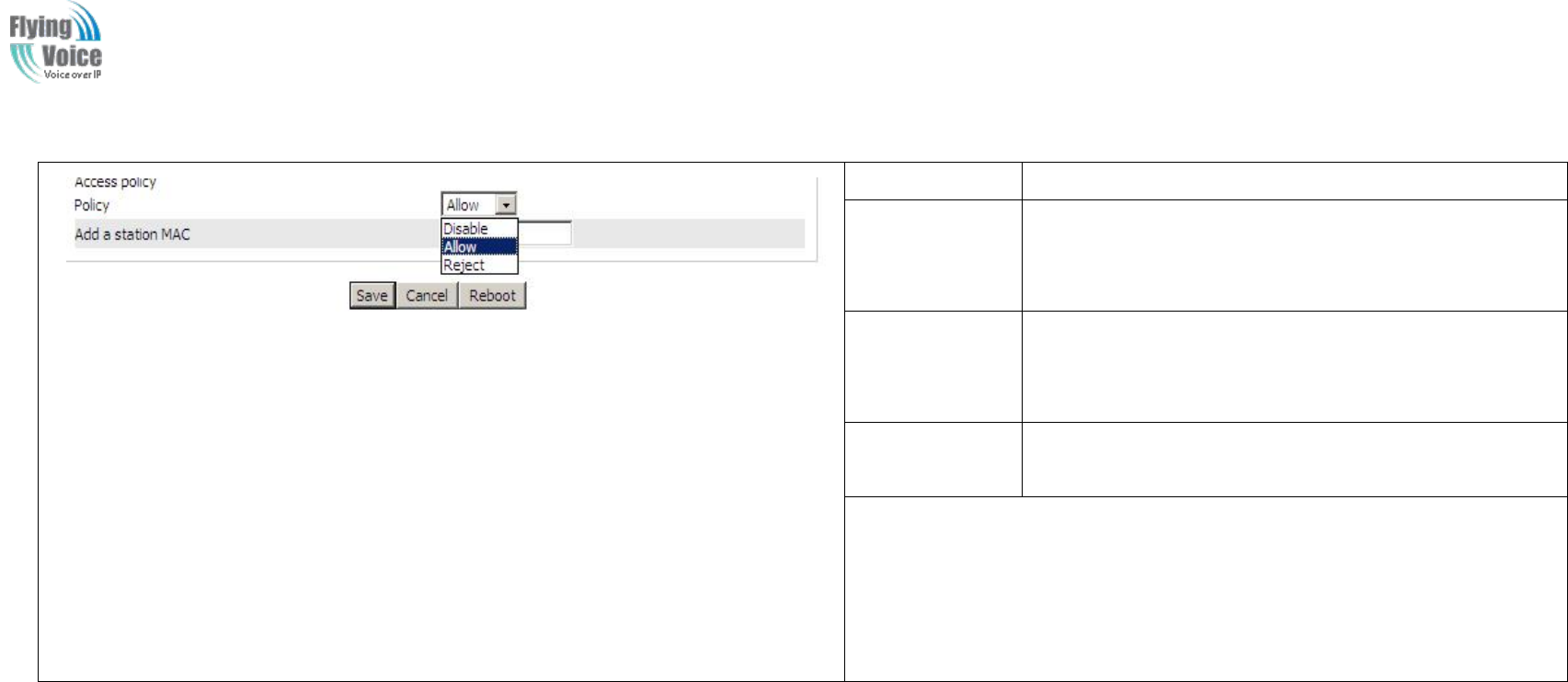
Copy Right 2017 All Rights Reserved by FLYINGVOICE TECHNOLOG LIMITED
V1.0
The page 39 of 78
Revision time: 2017-06-16 15:00
5.
5. Wireless
Wireless Access
Access Policy:
Policy:
Field Name
Description
Access policy
Wireless access control is used to allow or prohibit the
specified client to access to your wireless network based
on the MAC address.
Policy
Prohibition: disable wireless access control policy; allow:
only allow the clients in the list to access, rejected: block
the clients in the list to access.
Add a station
MAC
Enter the MAC address of the clients which you want to
allow or prohibit
Example: Prohibit the device whose wireless network card MAC address is
00:1F: D0: 62: BA: FF’s to access the wireless network, and allow other
computers to access the network.
Implementation: As shown, the Policy is Reject, add 00:1F: D0: 62: BA: FF to
the MAC, click Save and reboot the device settings to take effect.
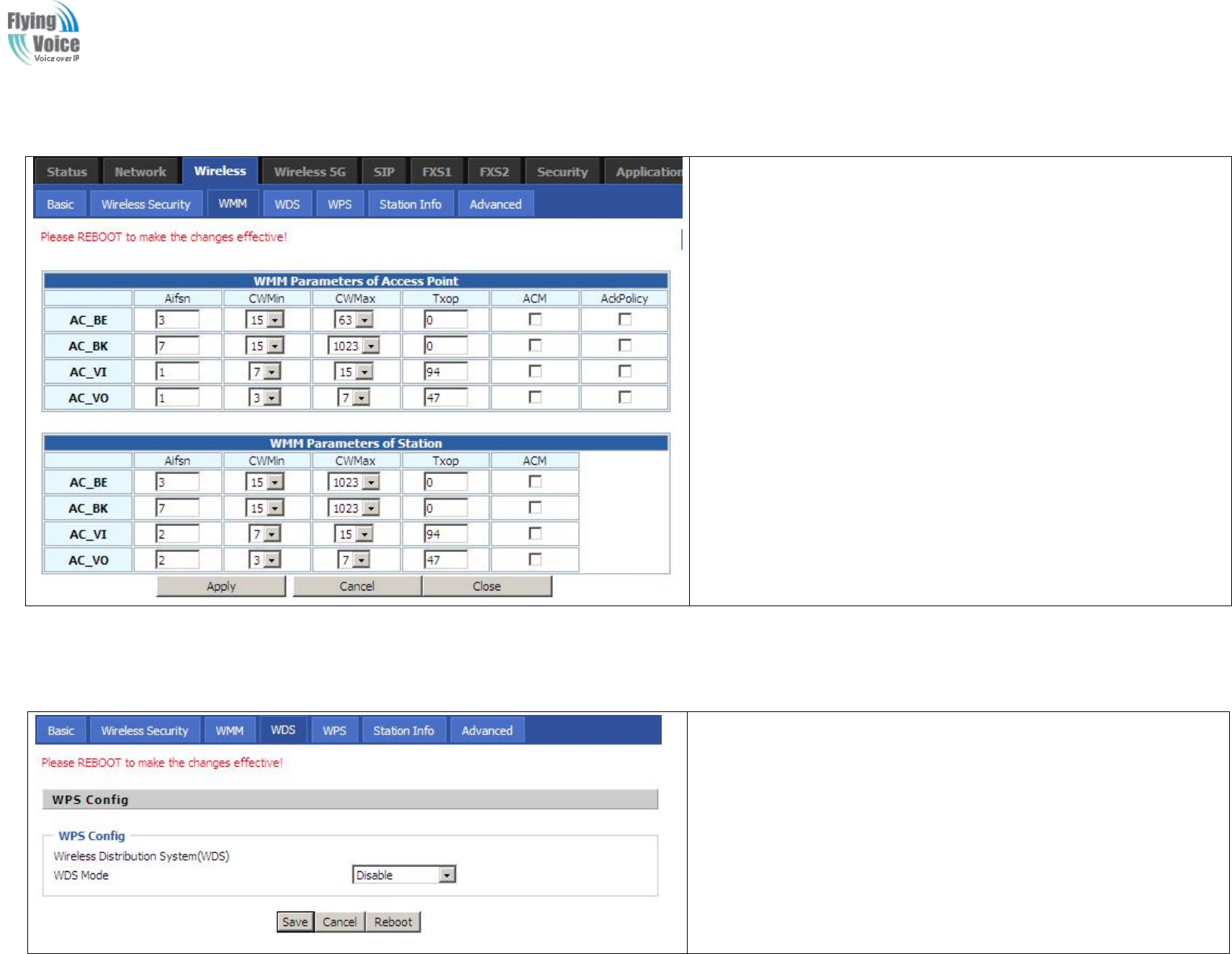
Copy Right 2017 All Rights Reserved by FLYINGVOICE TECHNOLOG LIMITED
V1.0
The page 40 of 78
Revision time: 2017-06-16 15:00
4.4.3 WMM
WMM (Wi-Fi MultiMedia) is the QoS certificate of Wi-Fi Alliance
(WFA). This provides you to configure the parameters of wireless
multimedia; VMM allows wireless communication to define a priority
according to the dhome gateway type. To make VMM effective, the
wireless clients must also support VMM.
4.4.4 WDS
If or not enable WDS mode
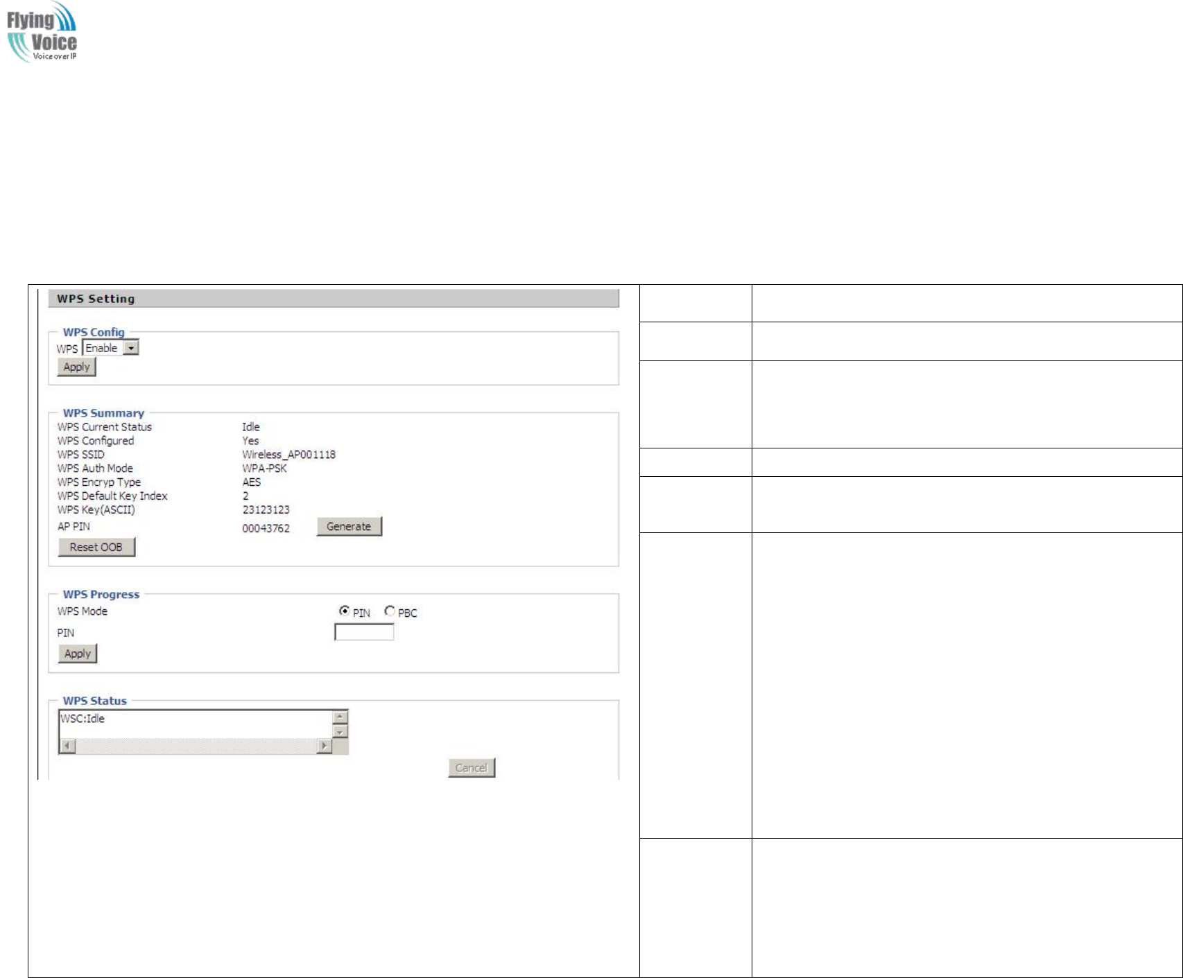
Copy Right 2017 All Rights Reserved by FLYINGVOICE TECHNOLOG LIMITED
V1.0
The page 41 of 78
Revision time: 2017-06-16 15:00
4.4.5 WPS
WPS
WPS (Wi-Fi
(Wi-Fi Protected
Protected Setup)
Setup) provides
provides easy
easy procedure
procedure to
to make
make network
network connection
connection between
between wireless
wireless station
station and
and wireless
wireless access
access point
point (vigor
(vigor
router)
router) with
with the
the encryption
encryption of
of WPA
WPA and
and WPA2.
WPA2.
It
It is
is the
the simplest
simplest way
way to
to build
build connection
connection between
between wireless
wireless network
network clients
clients and
and vigor
vigor router.
router. Users
Users do
do not
not need
need to
to select
select any
any encryption
encryption mode
mode
and
and type
type any
any long
long encryption
encryption passphrase
passphrase to
to setup
setup a
awireless
wireless client
client every
every time.
time. He/she
He/she only
only needs
needs to
to press
press a
abutton
button on
on wireless
wireless client,
client, and
and WPS
WPS
will
will connect
connect for
for client
client and
and router
router automatically.
automatically.
Field Name
Description
WPS Setting
If or not enable WPS function
WPS
Summary
Display the current status of WPS, including current state,
SSSID name, authentication methods, encryption type and the
PIN code of this AP.
Generate
Generate a new PIN code
Reset OOB
FWR9202 uses default security policy to allow other
non-WPS users to access and apply.
WPS Mode
PIN :Enter the PIN code of the wireless device which
accesses to this LAN in the following option, and press apply.
Then FWR9202 begins to send signals, turn on the PIN
accessing method on the clients, and then it can access the
wireless AP automatically.
PBC:There are two ways to start PCB mode, user can press
the PCB button directly on the device, or select PCB mode on
the software and apply. Users can activate WPS connection in
WPS mode through these two methods, only when the clients
choose PCB access, the clients can connect the AP
automatically.
WPS Status
WPS shows status in three ways:
WSC: Idle
WSC: Start WSC Process(begin to send messages)
WSC: Success; this means clients have accessed the AP
successfully, WPS connects well.
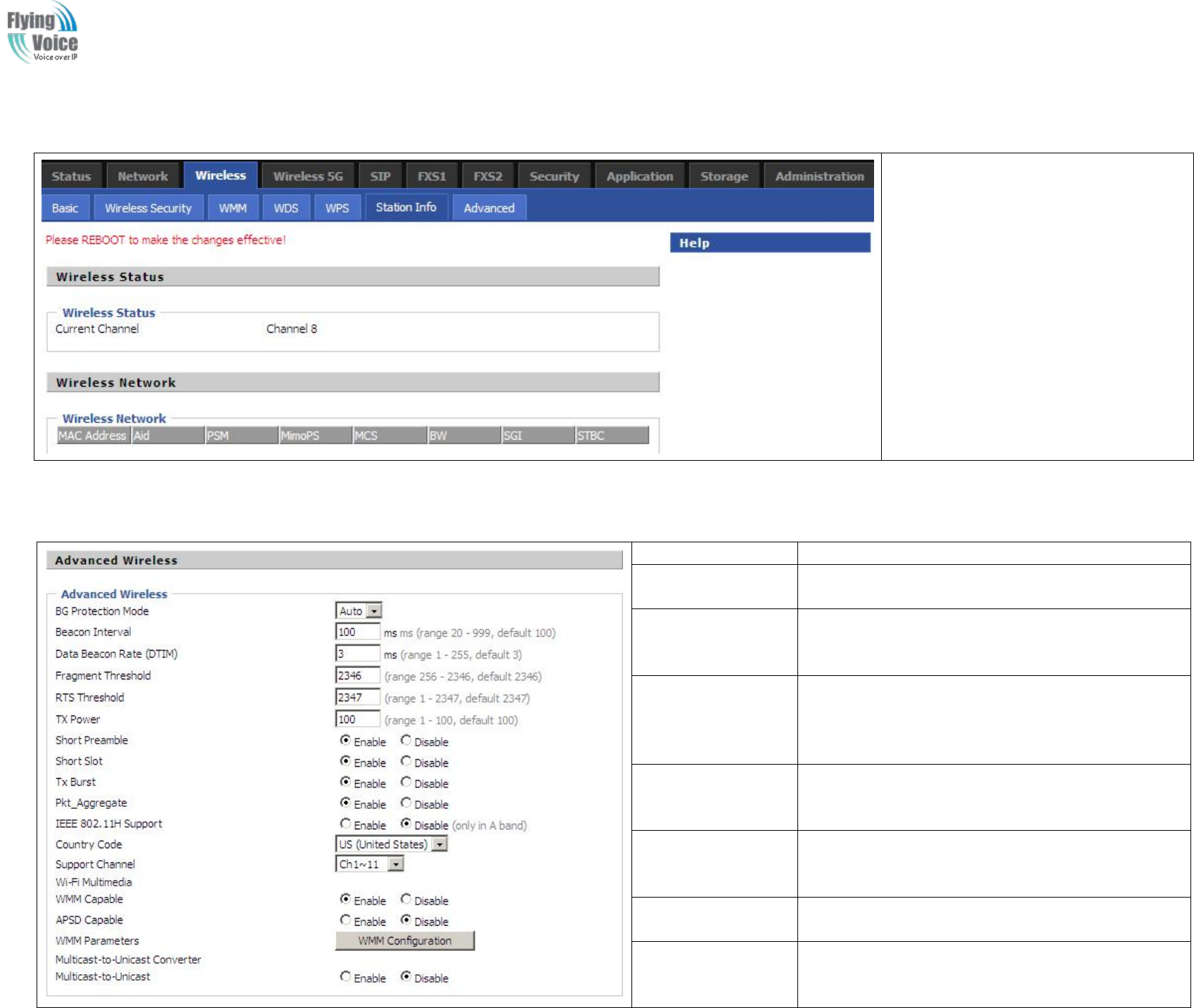
Copy Right 2017 All Rights Reserved by FLYINGVOICE TECHNOLOG LIMITED
V1.0
The page 42 of 78
Revision time: 2017-06-16 15:00
4.4.6 Station Info
This page shows user the clients’
information which connects to the AP.
4.4.7 Advanced
Field Name
Description
BG Protection Mode
Select G protection mode, options are on, off and
automatic.
Beacon Interval
The interval of sending a wireless beacon frame, within
this range, it will send a beacon frame for the
information of the surrounding radio network.
Data Beacon
Rate(DTIM)
Specify the interval of transmitting the indication
message, it is a kind of cut down operation, and it is
used for informing the next client which is going to
receive broadcast multi-cast.
Fragment Threshold
Specify the fragment threshold for the packet, when the
length of the packet exceeds this value, the packet will
be divided into multiple packets.
RTS Threshold
Specify the packet RTS threshold, when the packet
exceeds this value, the router will send RTS to the
destination site consultation
TX Power
Define the transmission power of the current AP, the
greater it is, the stronger the signal is.
Short Preamble
Default is enable, FWR9202 system is not compatible
with traditional IEEE802.11, the operation rate can be
1,2Mpbs

Copy Right 2017 All Rights Reserved by FLYINGVOICE TECHNOLOG LIMITED
V1.0
The page 43 of 78
Revision time: 2017-06-16 15:00
Short Slot
If or not enable short slot, default is enable, it is helpful
in improving the transmission rate of wireless
communication.
Tx Burst
One of the features of MAC layer, it is used to improve
the fairness for transmitting TCP.
Pkt_Aggregate
It is a mechanism that is used to enhance the LAN, in
order to ensure that the dhome gateway packets are sent
to the destination correctly.
IEEE802.11H
support
If or not enable IEEE802.11H Support, default is
disable.
Country Code
Select country code, options are CN, US, JP, FR, TW,
IE, HK and NONE.
Wi-Fi
Multimedia(WMM)
WMM Capable
If or not enable WMM. WMM take effects when it is
enabled.
APSD Capable
After enable this, it may affect wireless performance,
but can play a role in energy-saving power
WMM Parameters
Press , the webpage will jump to
the configuration page of Wi-Fi multimedia.
Multicast-to-Unicast
Converter
Multicast-to-Unicast
If or not enable Multicast-to-Unicast, by default, it is
disabled, you can enable it.
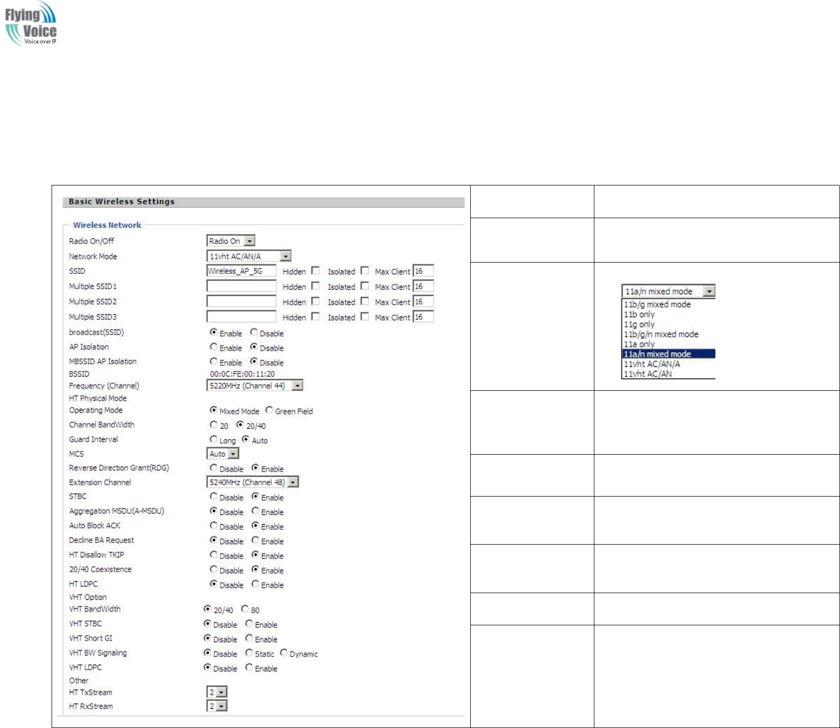
Copy Right 2017 All Rights Reserved by FLYINGVOICE TECHNOLOG LIMITED
V1.0
The page 44 of 78
Revision time: 2017-06-16 15:00
4.5 Wireless 5G
4.5.1 Basic
Field Name
Description
Radio on/off
Select “Radio Off” to disable wireless.
Select “Radio on”to enable wireless.
Network Mode
Choose one network mode from the drop down
list
SSID
It is the basic identity of wireless LAN. SSID
can be any alphanumeric or a combination of
special characters. It will appear in the wireless
network access list.
Multiple
SSID1~SSID3
FWR9202 supports multiple SSIDs.
Hidden
After the item is checked, the SSID is no
longer displayed in the search for the Wi-Fi
wireless network connection list
Broadcast(SSID)
After initial State opening, the device
broadcasts the SSID of the router to wireless
network
AP Isolation
If AP isolation is enabled, the clients of the AP
cannot access each other.
MBSSID AP
Isolation
AP isolation among the devices which are not
belong to this AP and along to, when the option
is enabled, the devices which do not belong to
this AP cannot access the devices which are
within the AP.

Copy Right 2017 All Rights Reserved by FLYINGVOICE TECHNOLOG LIMITED
V1.0
The page 45 of 78
Revision time: 2017-06-16 15:00
BSSID
A group of wireless stations and a WLAN
access point (AP) consists of a basic access
device (BSS), each computer in the BSS must
be configured with the same BSSID, that is, the
wireless AP logo.
Frequency (Channel)
You can select Auto Select and channel
1/2/3/4/5/6/7/8/9/10/11.
HT Physical Mode
Operating
Mode
1. Mixed Mode: In this mode, the previous
wireless card can recognize and connect to the
Pre-N AP, but the throughput will be affected
2. Green Field: high throughput can be
achieved, but it will affect backward
compatibility, and security of the system
Channel Bandwidth
Select channel bandwidth, default is 20MHz
and 20/40MHz.
Guard Interval
The default is automatic, in order to achieve
good BER performance, you must set the
appropriate guard interval
MCS
Position control signal, options are 0 to 32, the
default is automatic
Reverse Direction
(RDG)
You can choose to enable or disable this
privilege
STBC
VHT Bandwidth
VHT STBC
VHT Short GI
VHT BW Signaling
VHT LDPC
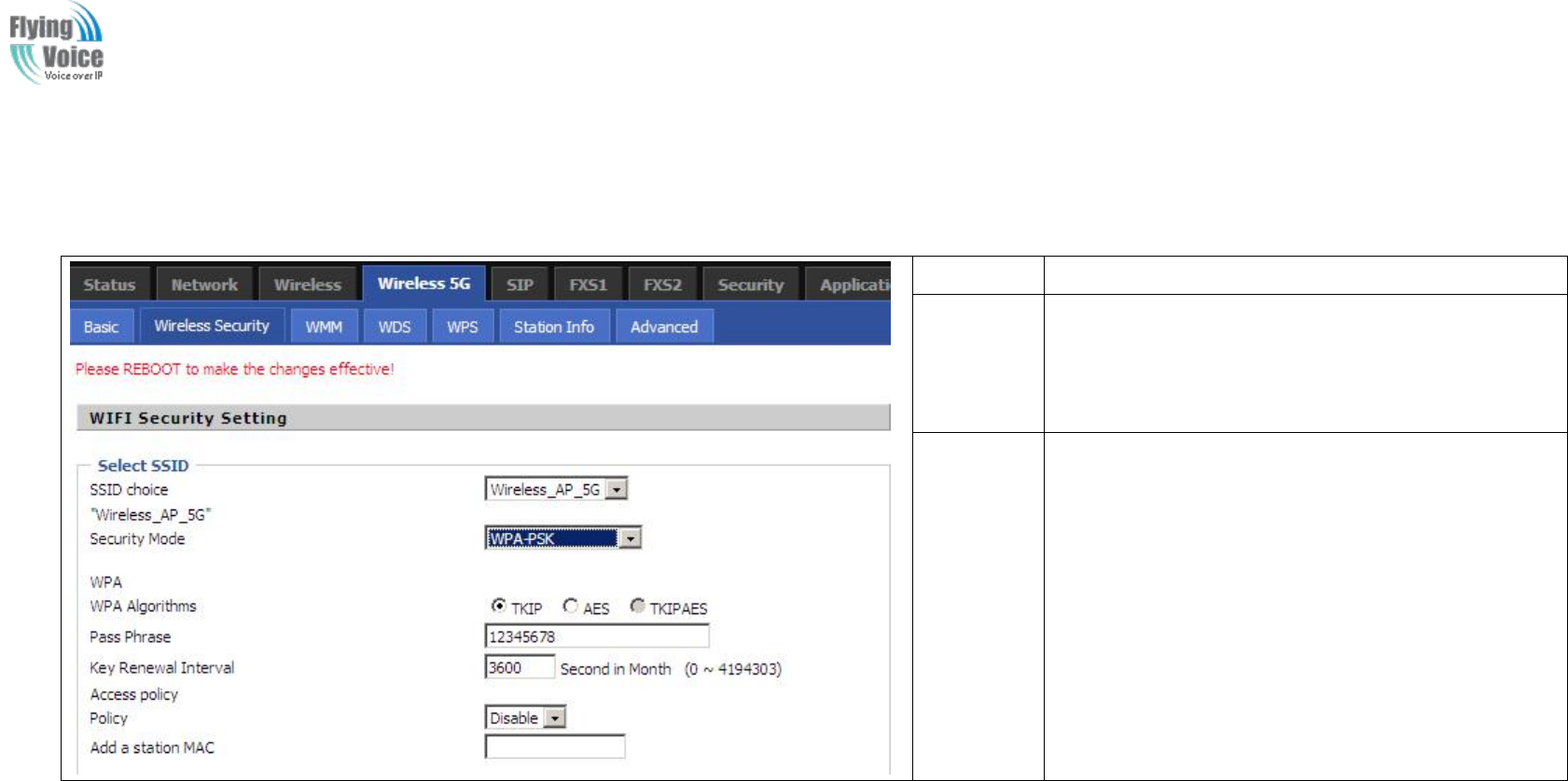
Copy Right 2017 All Rights Reserved by FLYINGVOICE TECHNOLOG LIMITED
V1.0
The page 46 of 78
Revision time: 2017-06-16 15:00
4.5.2 Wireless Security
Field Name
Description
SSID
Choice
Choose one SSID from SSID, Multiple SSID1,
Multiple SSID2 and Multiple SSID3.
Security
Mode
Select an appropriate encryption mode to improve
the security and privacy of your wireless data
packets.
Each encryption mode will bring out different web
page and ask you to offer additional configuration.
S
Select
elect a
adifferent
different encryption
encryption mode,
mode, the
the web
web interface
interface will
will be
be different,
different, user
user can
can configure
configure the
the corresponding
corresponding parameters
parameters under
under the
the mode
mode you
you
select.
select. Please
Please refer
refer to
to 4.4.2
4.4.2 section.
section.
4.5.3 WMM
Please
Please refer
refer to
to 4.4.3
4.4.3 section.
section.
4.5.4 WDS
Please
Please refer
refer to
to 4.4.4
4.4.4 section
section
4.5.5 WPS
Please
Please refer
refer to
to 4.4.5
4.4.5 section.
section.

Copy Right 2017 All Rights Reserved by FLYINGVOICE TECHNOLOG LIMITED
V1.0
The page 47 of 78
Revision time: 2017-06-16 15:00
4.5.6 Station Info
Please
Please refer
refer to
to 4.4.6
4.4.6 section.
section.
4.5.7 Advanced
Please
Please refer
refer to
to 4.4.7
4.4.7 section.
section.
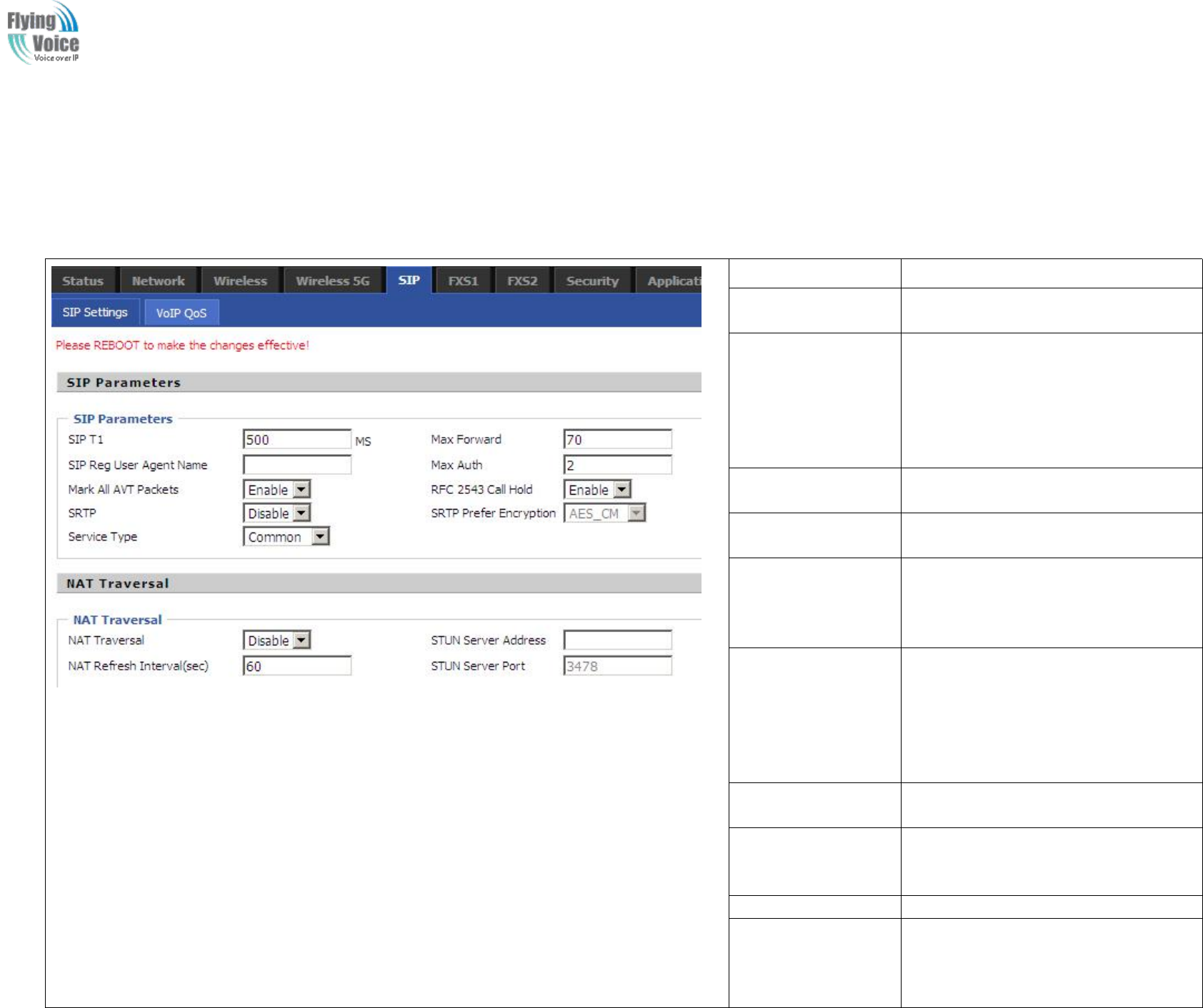
Copy Right 2017 All Rights Reserved by FLYINGVOICE TECHNOLOG LIMITED
V1.0
The page 48 of 78
Revision time: 2017-06-16 15:00
4.6 SIP
4.6.1 SIP Settings
Field Name
Description
SIP T1
The minimum scale of retransmission
time
Max Forward
Sip packets Max Forward message
header fields used to limit the request
which jump in his destination . To limit
the number that forwarding a request to
the proxy or gateway of next node
intermediate.
SIP Reg User Agent
Name
The agent name of SIP registered user
Max Auth
The maximum number of
retransmissions
Mark All AVT
Packets
Voice packet marking,to enable this item
will see the mark on the voice message
when the call environment changed (such
as press a key during the call)
RFC 2543 Call Hold
Enable,the Connection Information field
displays the address is 0.0.0.0 in the
invite message of Hold.
Disable,the Connection Information field
displays the device ip address in the
invite message of Hold.
SRTP
Whether to enable the call packet
encryption function
SRTP Prefer
Encryption
The preferred encryption type of calling
packet (the Message body of INVITE
Message)
Service Type
Choose the server type
NAT Traversal
1.If or not enable NAT Traversal
2. FWR9202 supports STUN Traversal;
If you want to traverse NAT/Firewall,
select the STUN.
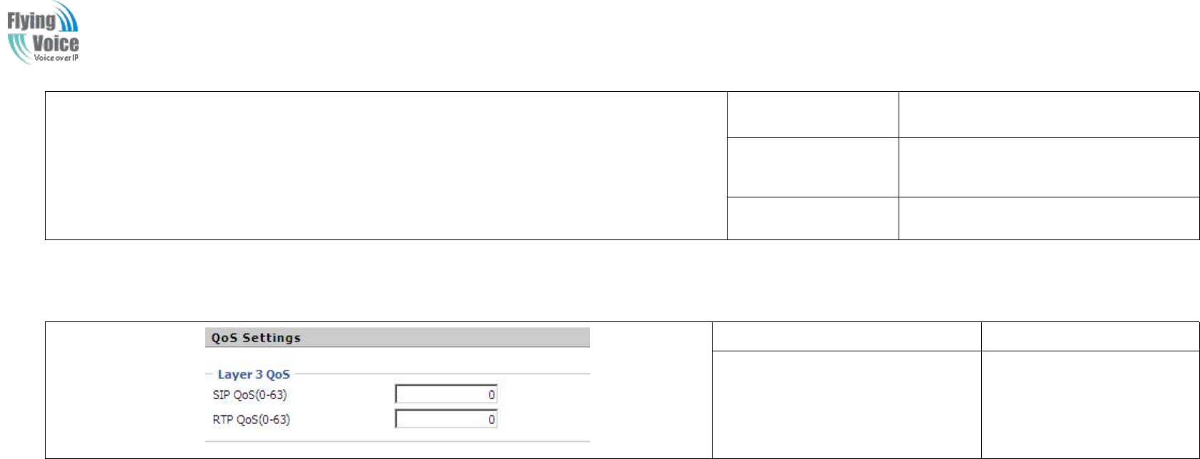
Copy Right 2017 All Rights Reserved by FLYINGVOICE TECHNOLOG LIMITED
V1.0
The page 49 of 78
Revision time: 2017-06-16 15:00
STUN Server
Address
Add the correct STUN service provider
IP address.
NAT Refresh
Interval
Set NAT Refresh Interval, default is 60s.
STUN Server Port
Set STUN Server Port, default is 5060.
4.6.2 VoIP Qos
Field Name
Description
SIP /RTP QoS
The default value is 0,you
can set a range of values is
0~63
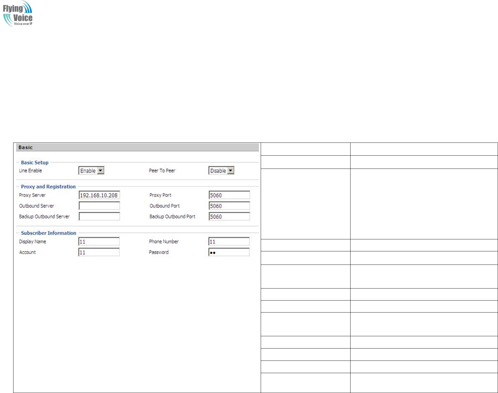
Copy Right 2017 All Rights Reserved by FLYINGVOICE TECHNOLOG LIMITED
V1.0
The page 50 of 78
Revision time: 2017-06-16 15:00
4.7 FXS1
4.7.1 SIP Account
1.
1. Basic
Basic
Set
Set the
the basic
basic information
information provided
provided by
by your
your VOIP
VOIP Service
Service Provider,
Provider, such
such as
as Phone
Phone Number,
Number, Account,
Account, password,
password, SIP
SIP Proxy
Proxy and
and so
so on.
on.
Field Name
Description
Line Enable
If or not enable the line.
Peer To Peer
If or not enable PEER to PEER.
If enable, SIP-1 will not send register request to
SIP server; but in Status/ SIP Account Status
webpage, Status is Registered; lines 1 can dial
out, but the external line number cannot dialed
line1.
Proxy Server
The IP address or the domain of SIP Server
Outbound Server
The IP address or the domain of Outbound Server
Backup Outbound Server
The IP address or the domain of Backup
Outbound Server
Proxy port
SIP Service port, default is 5060
Outbound Port
Outbound Proxy’s Service port, default is 5060
Backup Outbound Port
Backup Outbound Proxy’s Service port, default is
5060
Display Name
The number will be displayed on LCD
Phone Number
Enter telephone number provided by SIP Proxy
Account
Enter SIP account provided by SIP Proxy
Password
Enter SIP password provided by SIP Proxy
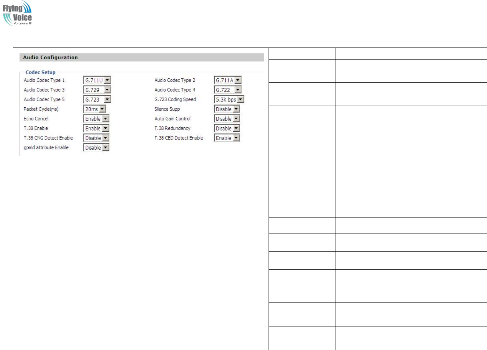
Copy Right 2017 All Rights Reserved by FLYINGVOICE TECHNOLOG LIMITED
V1.0
The page 51 of 78
Revision time: 2017-06-16 15:00
2.
2. Audio
Audio Configuration
Configuration
Field Name
Description
Audio Codec Type1
Choose the audio codec type from G.711U, G.711A,
G.722, G.729, G.723
Audio Codec Type2
Choose the audio codec type from G.711U, G.711A,
G.722, G.729, G.723
Audio Codec Type3
Choose the audio codec type from G.711U, G.711A,
G.722, G.729, G.723
Audio Codec Type4
Choose the audio codec type from G.711U, G.711A,
G.722, G.729, G.723
Audio Codec Type5
Choose the audio codec type from G.711U, G.711A,
G.722, G.729, G.723
G.723 Coding Speed
Choose the speed of G.723 from 5.3kbps and
6.3kbps
Packet Cycle
The RTP packet cycle time, default is 20ms
Silence Supp
If or not enable silence
Echo Cancel
If or not enable echo cancel, default is enable
Auto Gain Control
If or not enable auto gain.
T.38 Enable
If or not enable T.38
T.38 Redundancy
If or not enable T.38 Redundancy
T.38 CNG Detect
Enable
If or not enable T.38 CNG Detect
gmd attribute
Enable
If or not enable gmd attribute.
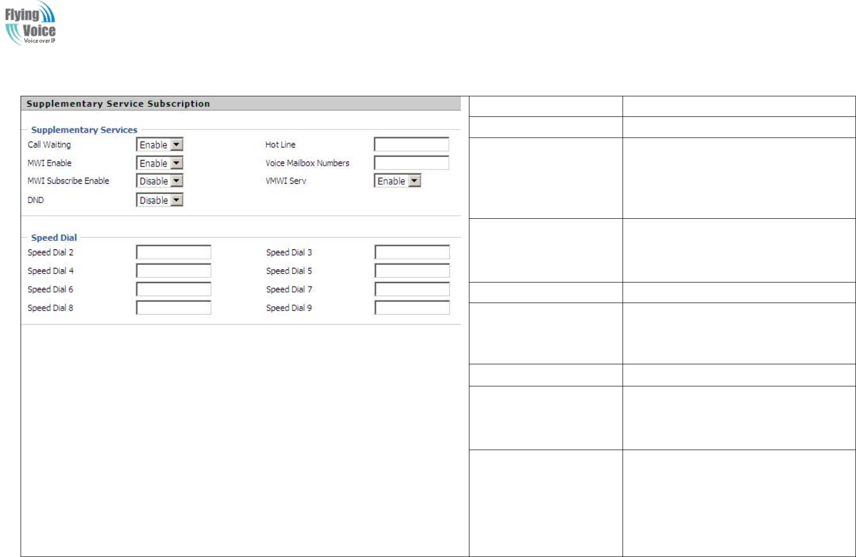
Copy Right 2017 All Rights Reserved by FLYINGVOICE TECHNOLOG LIMITED
V1.0
The page 52 of 78
Revision time: 2017-06-16 15:00
3.
3. Supplementary
Supplementary Service
Service Subscription
Subscription
Field Name
Description
Call Waiting
If or not enable Call Waiting
Hot Line
Fill in the hotline number.
Pickup handset or press handsfree/headset
button, the device will dial out the hotline
number automatically.
MWI Enable
If or not enable MWI (message waiting
indicate). If the user needs to user voice mail,
please enable this feature.
MWI Subscribe Enable
If or not enable MWI Subscribe
Voice Mailbox Numbers
Fill in the voice mailbox phone number,
Asterisk platform, for example, its default
voice mail is *97
VMWI Serv
If or not enable VMWI service.
DND
If or not enable DND (do not disturb).
If enable, any phone call cannot arrive at the
device; default is disable.
Speed Dial
Enter the speed dial phone numbers.
Dial *74 to active speed dial function.
Then press the speed dial numbers, for
example, press 2, phone will dial
075526099365 directly.
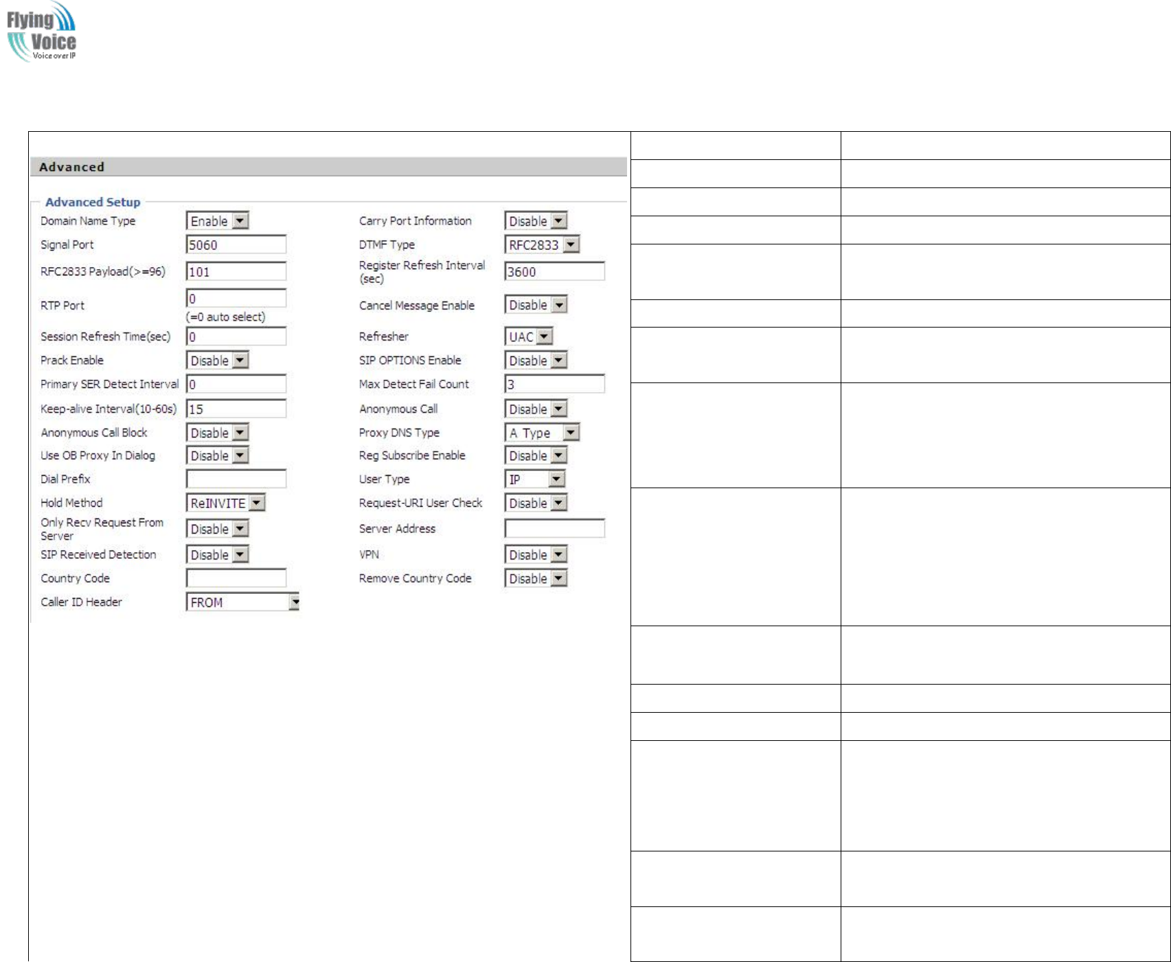
Copy Right 2017 All Rights Reserved by FLYINGVOICE TECHNOLOG LIMITED
V1.0
The page 53 of 78
Revision time: 2017-06-16 15:00
4.
4. Advanced
Advanced
Field Name
Description
Domain Name Type
If or not use domain name in the SIP URI.
Carry Port Information
If or not carry port information in the SIP URI.
Signal Port
The local port of SIP protocol, default is 5060.
DTMF Type
Choose the DTMF type from Inbound,
RFC2833 and SIP INFO.
RFC2833 Payload(>=96)
User can use the default setting.
Register Refresh Interval
The interval between two normal Register
messages. You can use the default setting.
RTP Port
Set the port to send RTP.
The device will select one idle port for RTP if
you set “0”; otherwise use the value which user
sets.
Cancel Message Enable
When you set enable, an unregistered message
will be sent before registration, while you set
disable, unregistered message will not be sent
before registration. You should set the option
for different Proxy.
Session Refresh Time(sec)
Time interval between two sessions, you can
use the default settings.
Refresher
Choose refresher from UAC and UAS.
Prack Enable
If or not enable prack.
SIP OPTIONS Enable
When you set enable, the device will send
SIP-OPTION to the server, instead of sending
periodic Hello message. The sending interval is
Keep-alive interval.
Primary SER Detect
Interval
Test interval of the primary server, the default
value is 0, it represents disable.
Max Detect Fail Count
Interval of detection of the primary server fail;
the default value is 3, it means that if detect 3
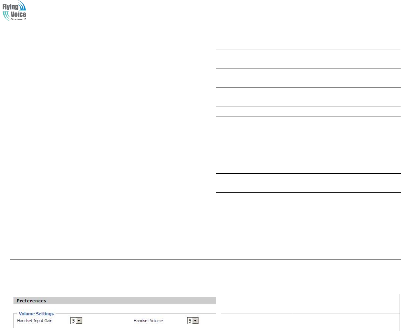
Copy Right 2017 All Rights Reserved by FLYINGVOICE TECHNOLOG LIMITED
V1.0
The page 54 of 78
Revision time: 2017-06-16 15:00
times fail; the device will no longer detect the
primary server.
Keep-alive Interval(10-60s)
The interval that the device will send an empty
packet to proxy.
Anonymous Call
If or not enable anonymous call.
Anonymous Call Block
If or not enable anonymous call block.
Proxy DNS Type
Set the DNS server type, choose from A type
and DNS SRV.
Use OB Proxy In Dialog
If or not use OB Proxy In Dialog.
Reg Subscribe Enable
If enable, subscribing will be sent after
registration message, if not enable, do not send
subscription.
Dial Prefix
The number will be added before your
telephone number when making calls.
User Type
Choose the User Type from IP and Phone.
Hold Method
Choose the Hold Method from ReINVITE and
INFO.
Request-URI User Check
If or not enable the user request URI check.
Only Recv request from
server
If or not enable the only receive request from
server.
Server Address
The IP address of SIP server.
SIP Received Detection
If or not enable SIP Received Detection, if
enable, use it to confirm the public network
address of the device.
4.7.2 Preferences
1.
1. Volume
Volume Settings
Settings
Field Name
Description
Handset Input Gain
Adjust the handset input gain from 0 to 7.
Handset Volume
Adjust the output gain from 0 to 7.
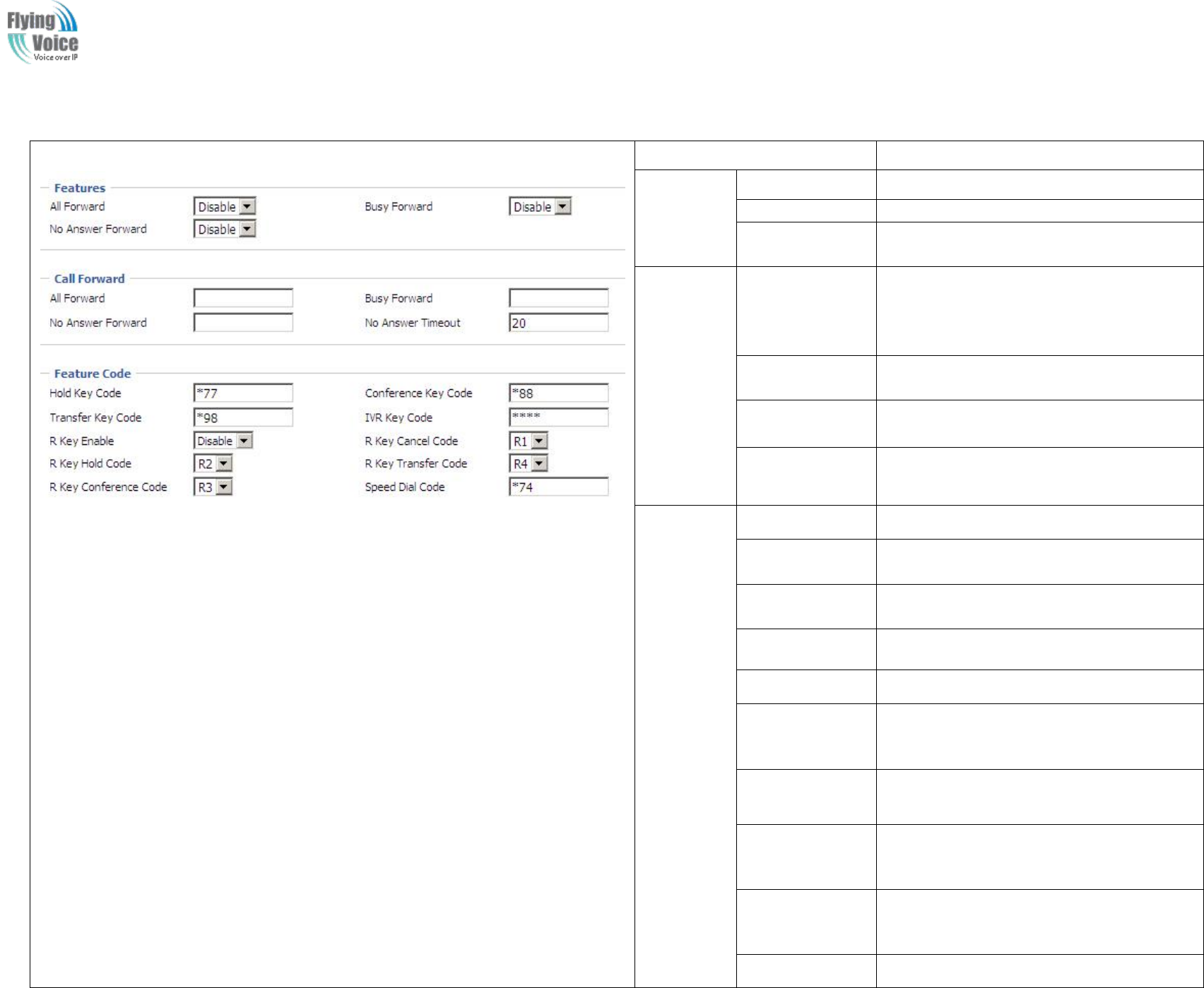
Copy Right 2017 All Rights Reserved by FLYINGVOICE TECHNOLOG LIMITED
V1.0
The page 55 of 78
Revision time: 2017-06-16 15:00
2.
2. Features
Features and
and Call
Call Forward
Forward
Field Name
Description
Features
All Forward
If or not enable forward all calls
Busy Forward
If or not enable busy forward.
No Answer
Forward
If or not enable no answer forward.
Call
Forward
All Forward
Set the target phone number for all forward.
The device will forward all calls to the phone
number immediately when there is an
incoming call.
Busy Forward
The phone number which the calls will be
forwarded to when line is busy.
No Answer
Forward
The phone number which the call will be
forwarded to when there's no answer.
No Answer
Timeout
The seconds to delay forwarding calls, if
there is no answer at your phone.
Feature
Code
Hold key code
Call hold signatures, default is *77.
Conference key
code
Signature of the tripartite session, default is
*88.
Transfer key
code
Call forwarding signatures ,default is *98.
IVR key code
Signatures of the voice menu, default is ****.
R key enable
If or not enable R key way call features.
R key cancel
code
Set the R key cancel code, option are ranged
from R1 to R9, default value is R1.
R key hold code
Set the R key hold code, options are ranged
from R1 to R9, default value is R2.
R key transfer
code
Set the R key transfer code, options are
ranged from R1 to R9, default value is R4.
R key conference
code
Set the R key conference code, options are
ranged from R1 to R9, default value is R3.
Speed Dial Code
Speed dial code, default is *74.
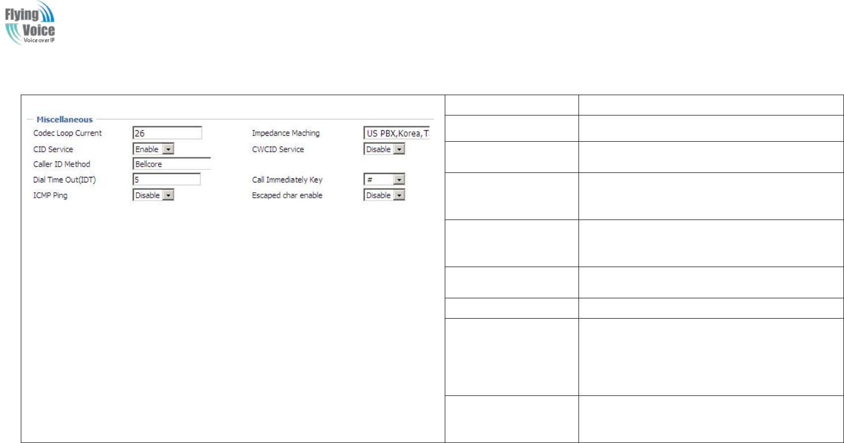
Copy Right 2017 All Rights Reserved by FLYINGVOICE TECHNOLOG LIMITED
V1.0
The page 56 of 78
Revision time: 2017-06-16 15:00
3.
3. Miscellaneous
Miscellaneous
Field Name
Description
Codec Loop Current
Set off-hook loop current, default is 26
Impedance Maching
Set impedance matching, default is US
PBX,Korea,Taiwan(600).
CID service
If or not enable displaying caller ID; If enable, caller
ID is displayed when there is an incoming call or it
won’t be displayed. Default is enable.
CWCID Service
If or not enable CWCID. If enable, the device will
display the waiting call’s caller ID, or it won’t
display. Default is disable.
Dial Time Out
How long FWR9202 will sound dial out tone when
FWR9202 dials a number.
Call Immediately Key
Choose call immediately key form * or #.
ICMP Ping
If or not enable ICMP Ping.
If enable this option, home gateway will ping the SIP
Server every interval time, otherwise, It will send
“hello” empty packet to the SIP Server.
Escaped char enable
Open special character translation function; if
enable, when you press the # key, it will be translated
to 23%, when disable, it is just #
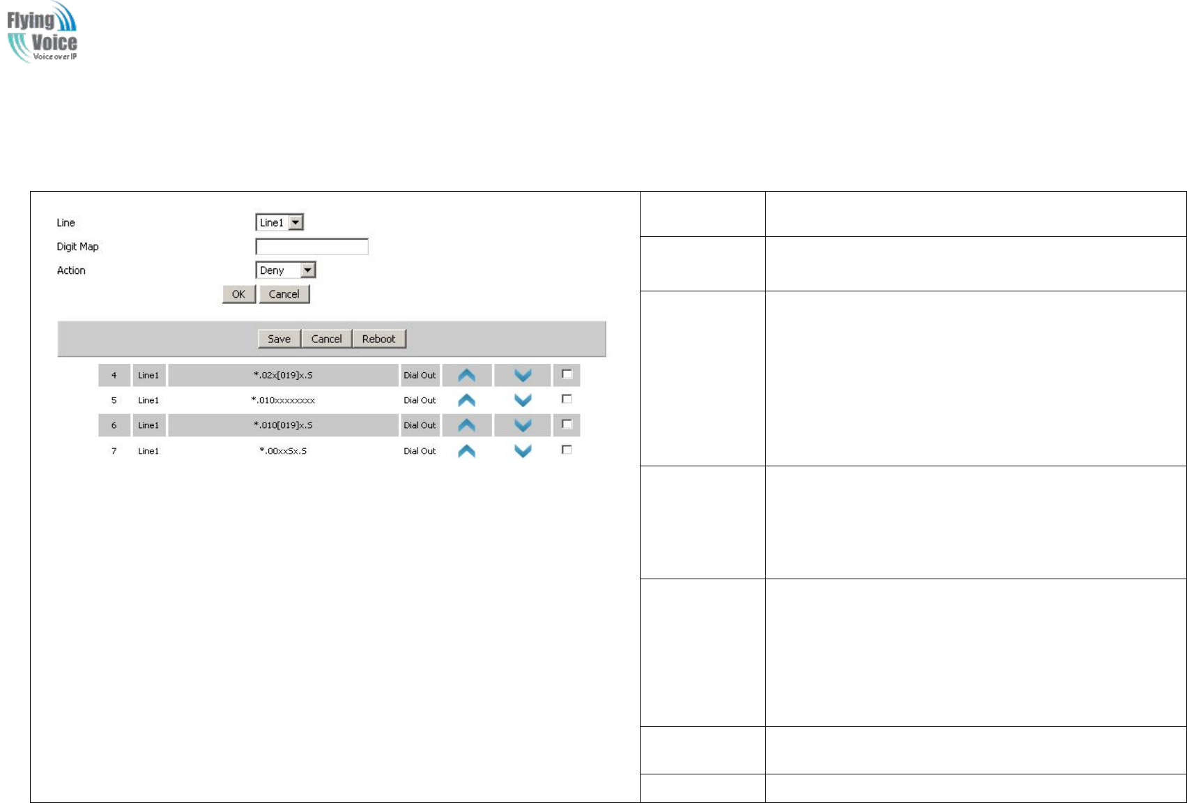
Copy Right 2017 All Rights Reserved by FLYINGVOICE TECHNOLOG LIMITED
V1.0
The page 57 of 78
Revision time: 2017-06-16 15:00
4.7.3 Dial Plan
1.
1. Parameters
Parameters and
and Settings
Settings
Field Name
Description
Dial Plan
If or not enable dial plan.
Line
Set the line.
Digit Map
Fill in the sequence used to match input number
The syntactic, please refer to the following Dial Plan
Syntactic
Action
Choose the dial plan mode from Deny and Dial Out.
Deny means FWR9202 will reject the matched number,
while Dial Out means FWR9202 will dial out the matched
number.
Move Up
Press it to move up.
Move Down
Press it to move down.
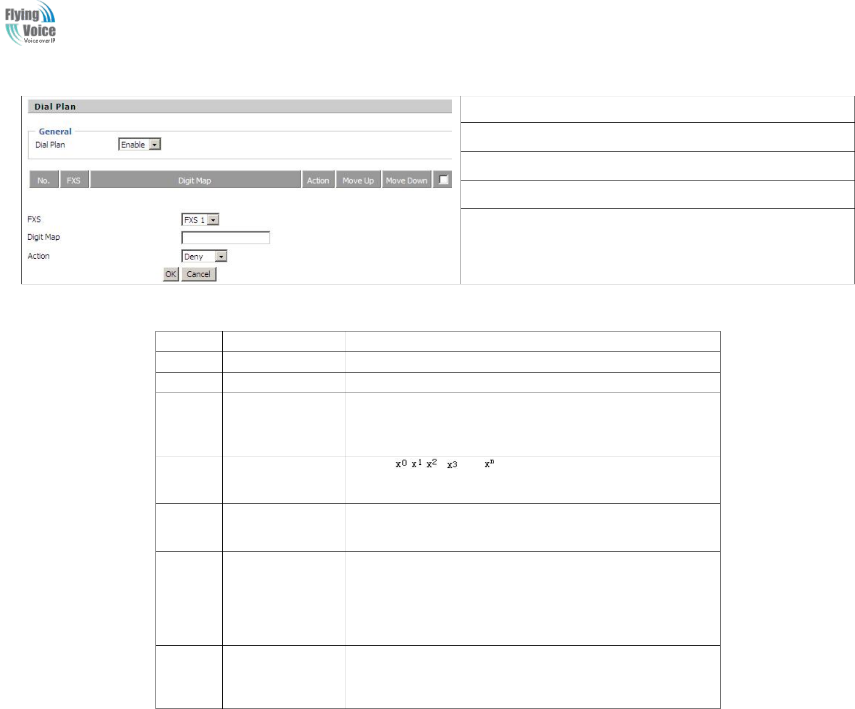
Copy Right 2017 All Rights Reserved by FLYINGVOICE TECHNOLOG LIMITED
V1.0
The page 58 of 78
Revision time: 2017-06-16 15:00
2.
2. Adding
Adding one
one dial
dial plan:
plan:
Step 1. Enable Dial Plan
Step 2. Click Add button, and the configuration table
Step 3. Fill in the value of parameters.
Step 4.Press OK button to end configuration.
Step 5. Press Save button to save changes
3.
3. Dial
Dial Plan
Plan Syntactic
Syntactic
No.
String
Description
1
0 1 2 3 4 5 6 7 8 9 * #
Legal characters
2
x
Lowercase letter x stands for one legal character
3
[sequence]
To match one character form sequence.
For example:
6. [0-9]: match one digit form 0 to 9
7. [23-5*]: match one character from 2 or 3 or 4 or 5 or *
4
x.
Match to , , , …...
For example:
“01.”:can match ”0”, “01”, “011”, ”0111”, …….., ”01111…”
5
<dialed:substituted>
Replace dialed with substituted.
For example:
<8:1650>123456:input is “85551212”, output is“16505551212”
6
x,y
Make outside dial tone after dialing “x”, stop until dialing character “y”
For example:
“9,1xxxxxxxxxx”:the device reports dial tone after inputting “9”, stops
tone until inputting “1”
“9,8,010x”: make outside dial tone after inputting “9”, stop tone until
inputting “0”
7
T
Set the delayed time.
For example:
“<9:111>T2”: The device will dial out the matched number “111” after 2
seconds.
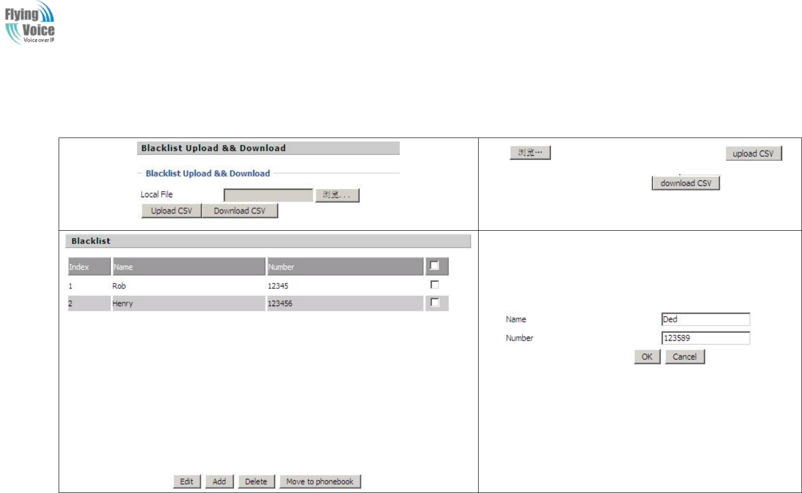
Copy Right 2017 All Rights Reserved by FLYINGVOICE TECHNOLOG LIMITED
V1.0
The page 59 of 78
Revision time: 2017-06-16 15:00
4.7.4 Blacklist
In
In this
this page,
page, user
user can
can upload
upload or
or download
download blacklist
blacklist file,
file, and
and can
can add
add or
or delete
delete or
or edit
edit blacklist
blacklist one
one by
by one.
one.
Click to select the blacklist file and click to
upload it to FWR9202; Click to save the
blacklist file to your local computer.
Select one contact and click edit to change the information, click
delete to delete the contact, click Move to phonebook to move the
contact to phonebook.
Click Add to add one blacklist, enter the name and phone number,
click OK to confirm and click cancel to cancel.
4.7.5 Call Log
To
To view
view the
the call
call log
log information
information such
such as
as redial
redial list
list (incoming
(incoming call),
call), answered
answered call
call and
and missed
missed cal
cal

Copy Right 2017 All Rights Reserved by FLYINGVOICE TECHNOLOG LIMITED
V1.0
The page 60 of 78
Revision time: 2017-06-16 15:00
Redial List
Answered Calls
Missed Call
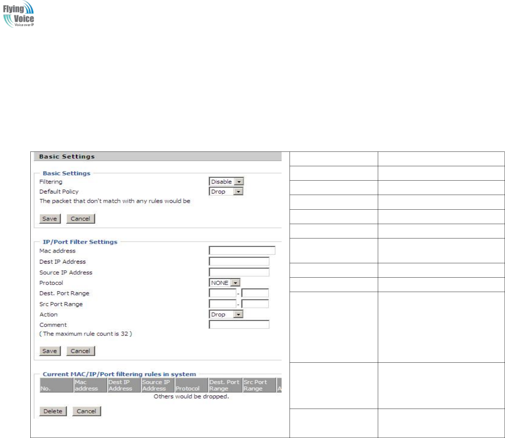
Copy Right 2017 All Rights Reserved by FLYINGVOICE TECHNOLOG LIMITED
V1.0
The page 61 of 78
Revision time: 2017-06-16 15:00
4.8 FXS2
The
The settings
settings of
of FXS2
FXS2 are
are the
the same
same as
as FXS1.
FXS1.
4.9 Security
4.9.1 Filtering Setting
Field Name
Description
Filtering
If or not enable filter function
Default Policy
Choose to give up or accept
Mac address
Add the Mac address filtering
Dest IP address
Dest IP address
Source IP address
Source IP address
Protocol
Select a protocol name, support for TCP,
UDP and TCP&UDP
Dest. Port Range
Destination port ranges
Src Port Range
Source port range
Action
You can choose to receive or give up;
this should be consistent with the default
policy.
Comment
Add callout
Delete
Delete selected item
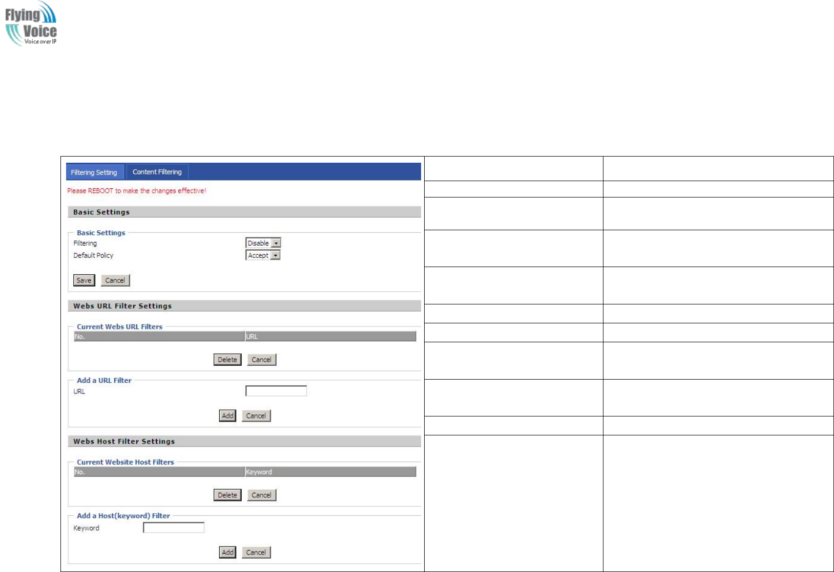
Copy Right 2017 All Rights Reserved by FLYINGVOICE TECHNOLOG LIMITED
V1.0
The page 62 of 78
Revision time: 2017-06-16 15:00
4.9.2 Content Filtering
Field Name
Description
Filtering
If or not enable content Filtering
Default Policy
The default policy is to accept or to prohibit
filtering rules
Current Webs URL Filters
List the URL filtering rules that already
existed (blacklist)
Delete/Cancel
You can choose to delete or cancel the
existing filter rules
Add a URL Filter
Add URL filtering rules
Add/Cancel
Click adds to add one rule or click cancel.
Current Website Host Filters
List the keywords that already exist
(blacklist)
Delete/Cancel
You can choose to delete or cancel the
existing filter rules the existing keywords.
Add a Host Filter(Keyword)
Add keywords
Add/Cancel
Click the Add or cancel
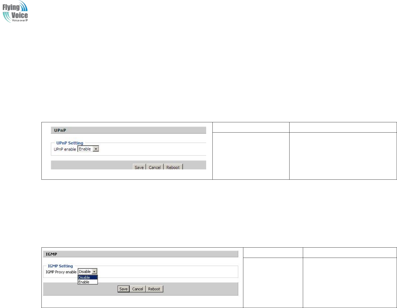
Copy Right 2017 All Rights Reserved by FLYINGVOICE TECHNOLOG LIMITED
V1.0
The page 63 of 78
Revision time: 2017-06-16 15:00
4.10 Application
4.10.1 UPnP
UPnP
UPnP (Universal
(Universal Plug
Plug and
and Play)
Play) support
support zero
zero setting
setting networking,
networking, and
and can
can automatically
automatically discover
discover a
avariety
variety of
of networked
networked devices.
devices. UPnP
UPnP is
is
enabled,
enabled, allows
allows the
the device
device supports
supports UPnP
UPnP function
function dynamically
dynamically access
access network,
network, obtain
obtain an
an IP
IP address,
address, and
and convey
convey its
its performance
performance information.
information.
If
If the
the network
network has
has a
aDHCP
DHCP and
and DNS
DNS server,
server, you
you can
can automatically
automatically obtain
obtain DHCP
DHCP and
and DNS
DNS services.
services.
Supports
Supports UPnP
UPnP devices
devices can
can be
be automatically
automatically off
off the
the network,
network, the
the device
device or
or other
other devices
devices on
on the
the network
network without
without affecting.
affecting.
Field Name
Description
UPnP enable
If or not enable UPnP function.
4.10.2 IGMP
Multicast
Multicast has
has the
the ability
ability to
to send
send the
the same
same data
data to
to multiple
multiple devices.
devices.
I
IP
Phosts
hosts use
use IGMP
IGMP (Internet
(Internet Group
Group Management
Management Protocol)
Protocol) report
report multicast
multicast group
group memberships
memberships to
to the
the neighboring
neighboring routers
routers to
to transmit
transmit data,
data, at
at the
the
same
same time,
time, the
the multicast
multicast router
router use
use IGMP
IGMP to
to discover
discover which
which hosts
hosts belong
belong to
to the
the same
same multicast
multicast group.
group.
Field Name
Description
IGMP Proxy enable
If or not enable IGMP function.
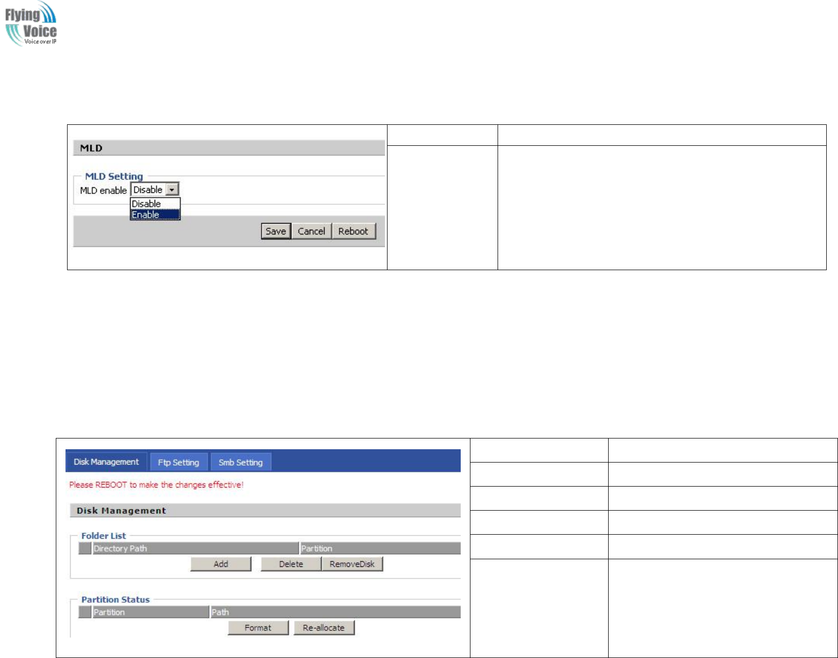
Copy Right 2017 All Rights Reserved by FLYINGVOICE TECHNOLOG LIMITED
V1.0
The page 64 of 78
Revision time: 2017-06-16 15:00
4.10.3 MLD
Field Name
Description
MLD enable
If or not enable MLD function
4.11 Storage
4.11.1 Disk Management
This
This page
page is
is used
used to
to manage
manage the
the USB
USB storage
storage device.
device.
Field Name
Description
Add
Adding files to the USB storage device
Delete
Remove the USB storage device file
Remove Disk
Transfer files within a USB storage device
Format
Format the USB storage device
Re-allocate
Resetting the USB storage device
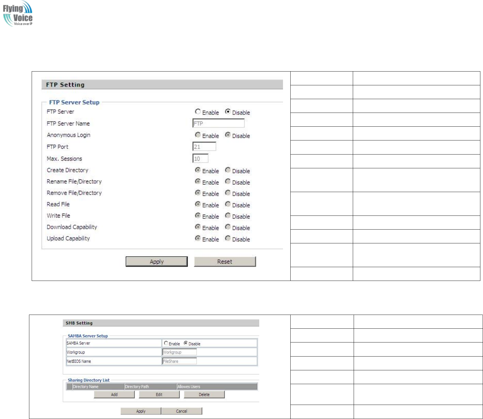
Copy Right 2017 All Rights Reserved by FLYINGVOICE TECHNOLOG LIMITED
V1.0
The page 65 of 78
Revision time: 2017-06-16 15:00
4.11.2 FTP Setting
Field Name
Description
FTP Server
If or not enable FTP server
FTP Server Name
Set the FTP server name
Anonymous Login
If or not support anonymous login
FTP Port
Set FTP server port number
Max. Sessions
Maximum number of connections
Create Directory
If or not enable create directory
Rename
File/Directory
If or not enable rename file/directory
Remove
File/Directory
If or not enable transfer of files/directories
Read File
If or not enable read files
Write File
If or not enable write files
Download
Capability
If or not enable download capability
function.
Upload Capability
If or not enable upload capability function
4.11.3 Smb Setting
Field Name
Description
SAMBA Server
If or not enable SAMBA server
Workgroup
Fill in the working group
NetBIOS Name
Network basic input/output system name
Add
Add a shared file
Edit
Edit a shared file
Del
Delete a shared file
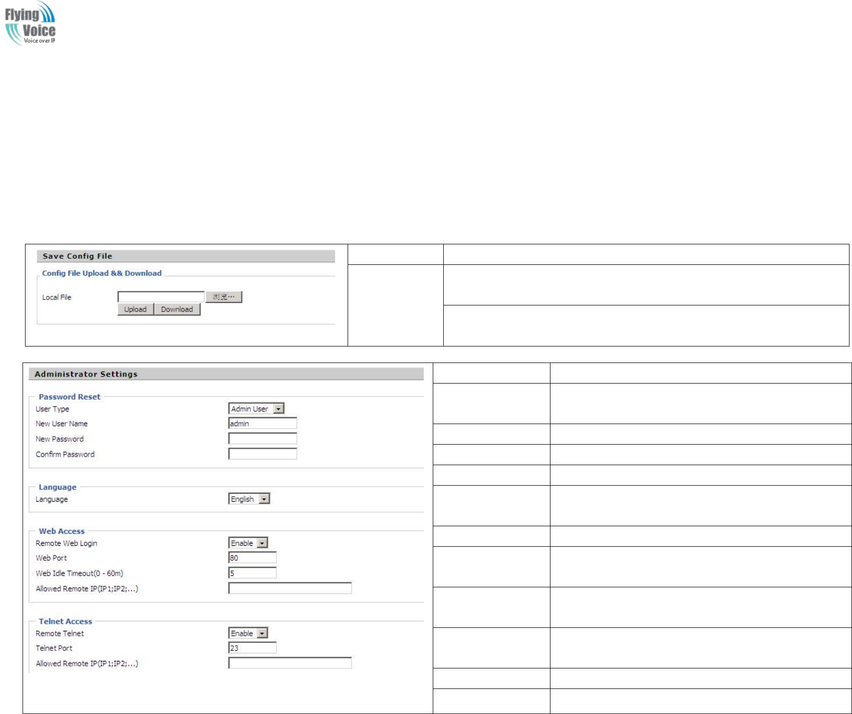
Copy Right 2017 All Rights Reserved by FLYINGVOICE TECHNOLOG LIMITED
V1.0
The page 66 of 78
Revision time: 2017-06-16 15:00
4.12 Administration
Use
Use can
can manage
manage the
the device
device in
in these
these webpage;
webpage; you
you can
can configur
configure
ethe
the Time/Date,
Time/Date, password,
password, web
web access,
access, system
system log
log and
and associated
associated
configuration
configuration TR069
TR069
4.12.1 Management
You
You can
can configur
configure
ethe
the value
value of
of Time/Date,
Time/Date, password,
password, web
web access,
access, and
and system
system log
log and
and so
so on.
on.
1.
1. Save
Save config
config file
file
Field Name
Description
Config file
upload and
download
Upload: click on browse, select file in the local, press the upload button to begin
uploading files
Download: click to download, and then select contains the path to download the
configuration file
2.
2. Administrator
Administrator settings
settings
Field Name
Description
User type
Choose the user type from admin user and normal user and
basic user.
New User Name
You can modify the user name, set up a new user name
New Password
Input the new password
Confirm Password
Input the new password again
Language
Select the language for the web, the device support Chinese,
English, and Spanish and so on.
Remote Web Login
If or not enable remote Web login
Web Port
Set the port value which is used to login from Internet port
and PC port, default is 80.
Web Idle timeout
Set the Web Idle timeout time. The webpage can be logged
out after Web Idle Timeout without any operation.
Allowed Remote
IP(IP1,IP2,...)
Set the IP which can login the device remotely.
Remote Telnet
If or not enable remote telnet login
Telnet Port
Set the port value which is used to telnet the device.
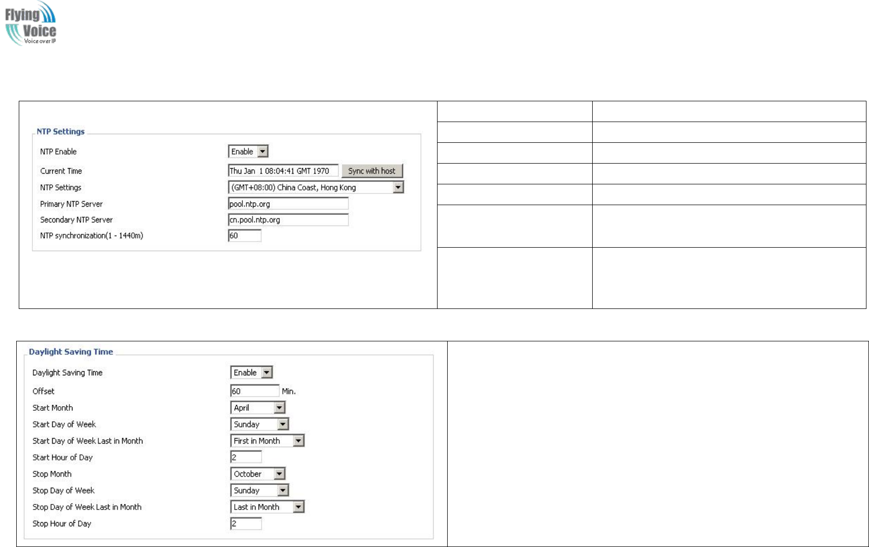
Copy Right 2017 All Rights Reserved by FLYINGVOICE TECHNOLOG LIMITED
V1.0
The page 67 of 78
Revision time: 2017-06-16 15:00
3.
3. NTP
NTP settings
settings
Field Name
Description
NTP Enable
If or not enable NTP
Current Time
Display current time
NTP Settings
Setting the Time Zone
Primary NTP Server
Primary NTP server's IP address or domain name
Secondary NTP Server
Options for NTP server's IP address or domain name
NTP synchronization
NTP synchronization cycle, cycle time can be 1 to
1440 minutes in any one, the default setting is 60
minutes
4.
4. Daylight
Daylight Saving
Saving Time
Time
Set the summer time steps:
Step 1. Enable Daylight Saving Time.
Step 2. Set value of offset, like the upon picture
Step 3: Set staring Month/Week/Day/Hour in Start Month/Start Day of Week
Last in Month/Start Day of Week/Start Hour of Day, analogously set stopping
Month/Week/Day/Hour in Stop Month/Stop Day of Week Last in Month/Stop
Day of Week/Stop Hour of Day.
Step 4.Press Saving button to save and press Reboot button to active changes.
5.
5. System
System Log
Log Setting
Setting
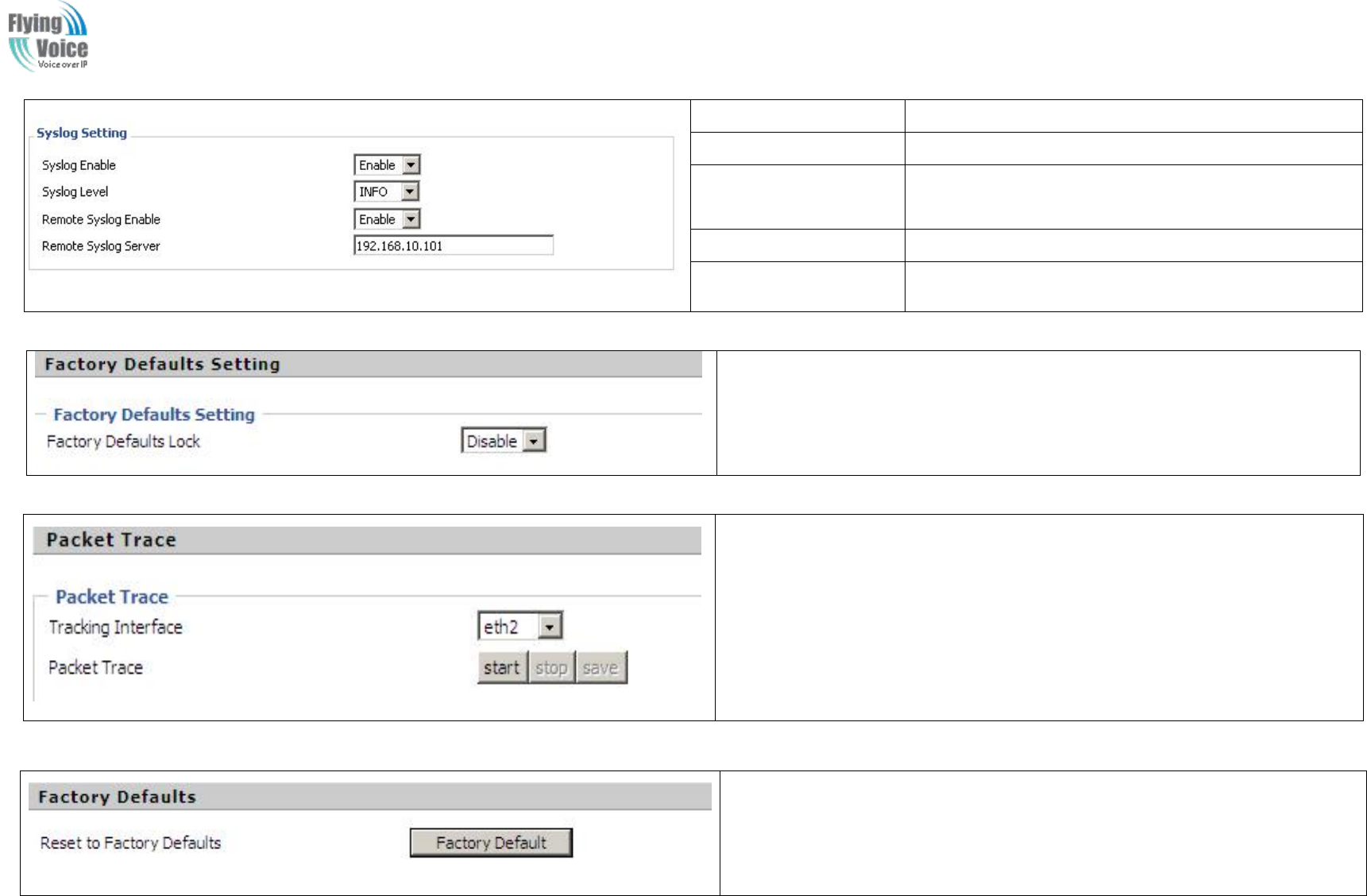
Copy Right 2017 All Rights Reserved by FLYINGVOICE TECHNOLOG LIMITED
V1.0
The page 68 of 78
Revision time: 2017-06-16 15:00
6.
6. Factory
Factory Defaults
Defaults Setting
Setting
If enable this function ,the device will not be restore factory settings
7.
7. Packet
Packet Trace
Trace
Users can use the packet trace feature intercepts the packets that were sent.
Click the Start button, start dhome gateway tracking and keep refreshing the page
until the message trace shows to stop, click the Save button to save captured
packets.
8.
8. Factory
Factory Defaults
Defaults
Click Factory Default to restore the residential gateway to factory settings.
Field Name
Description
Syslog Enable
If or not enable syslog function
Syslog Level
Select the system log, there is INFO and Debug two
grades, the Debug INFO can provide more information.
Remote Syslog Enable
If or not enable remote syslog function.
Remote Syslog server
Add a remote server IP address.
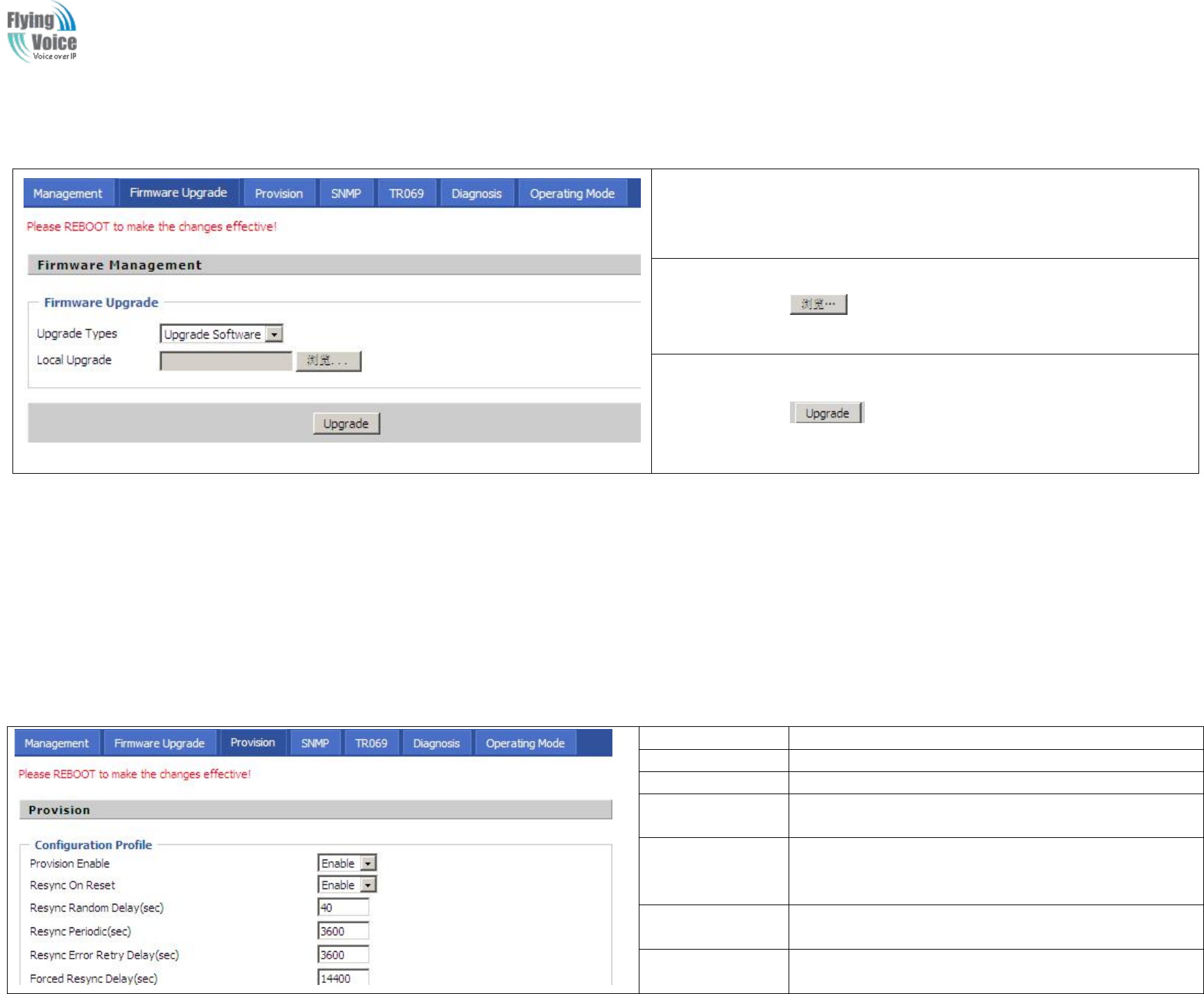
Copy Right 2017 All Rights Reserved by FLYINGVOICE TECHNOLOG LIMITED
V1.0
The page 69 of 78
Revision time: 2017-06-16 15:00
4.12.2 Firmware Upgrade
1. Choose upgrade file type from Image File and Dial Rule
2. Press to browser file.
3. Press to start upgrading.
4.12.3 Provision
Provisioning
Provisioning allow
allows
sFWR9202
FWR9202 auto-upgrading
auto-upgrading and
and auto-configuring
auto-configuring,
,and
and Flyingvoice
Flyingvoice devices
devices support
support TFTP,
TFTP, HTTP
HTTP and
and HTTPs
HTTPs three
three ways.
ways.
1.
1. Before
Before testing
testing or
or using
using TFTP,
TFTP, user
user should
should have
have tftp
tftp server
server and
and upgrading
upgrading file
file and
and configuring
configuring file.
file.
2.
2. Before
Before testing
testing or
or using
using HTTP,
HTTP, user
user should
should have
have http
http server
server and
and upgrading
upgrading file
file and
and configuring
configuring file.
file.
3.
3. Before
Before testing
testing or
or using
using HTTPS,
HTTPS, user
user should
should have
have https
https server
server and
and upgrading
upgrading file
file and
and configuring
configuring file
file and
and CA
CA Certificate
Certificate file(should
file(should same
same as
as
https
https server
server’
’s)
s) and
and Client
Client Certificate
Certificate file
file and
and Private
Private key
key file(HTTPS
file(HTTPS provision
provision will
will be
be supported
supported soon)
soon)
User
User can
can uploading
uploading CA
CA Certificate
Certificate file
file and
and Client
Client Certificate
Certificate file
file and
and Private
Private Key
Key file
file in
in Security
Security page.
page.
Field Name
Description
Provision Enable
If or not enable provision.
Resync on Reset
If or not enable resync after restart
Resync Random
Delay(sec)
Set the maximum delay for request the synchronization file,
default is 40.
Resync
Periodic(sec)
If the last resync was failure, FWR9202 will retry resync
after the “Resync Error Retry Delay ” time, default is
3600s.
Resync Error
Retry Delay(rec)
Set the periodic time for resync, default is 3600s.
Forced Resync
Delay(sec)
If it’s time to resync, but FWR9202 is busy now, in this
case, FWR9202 will wait for a period time, the longest is
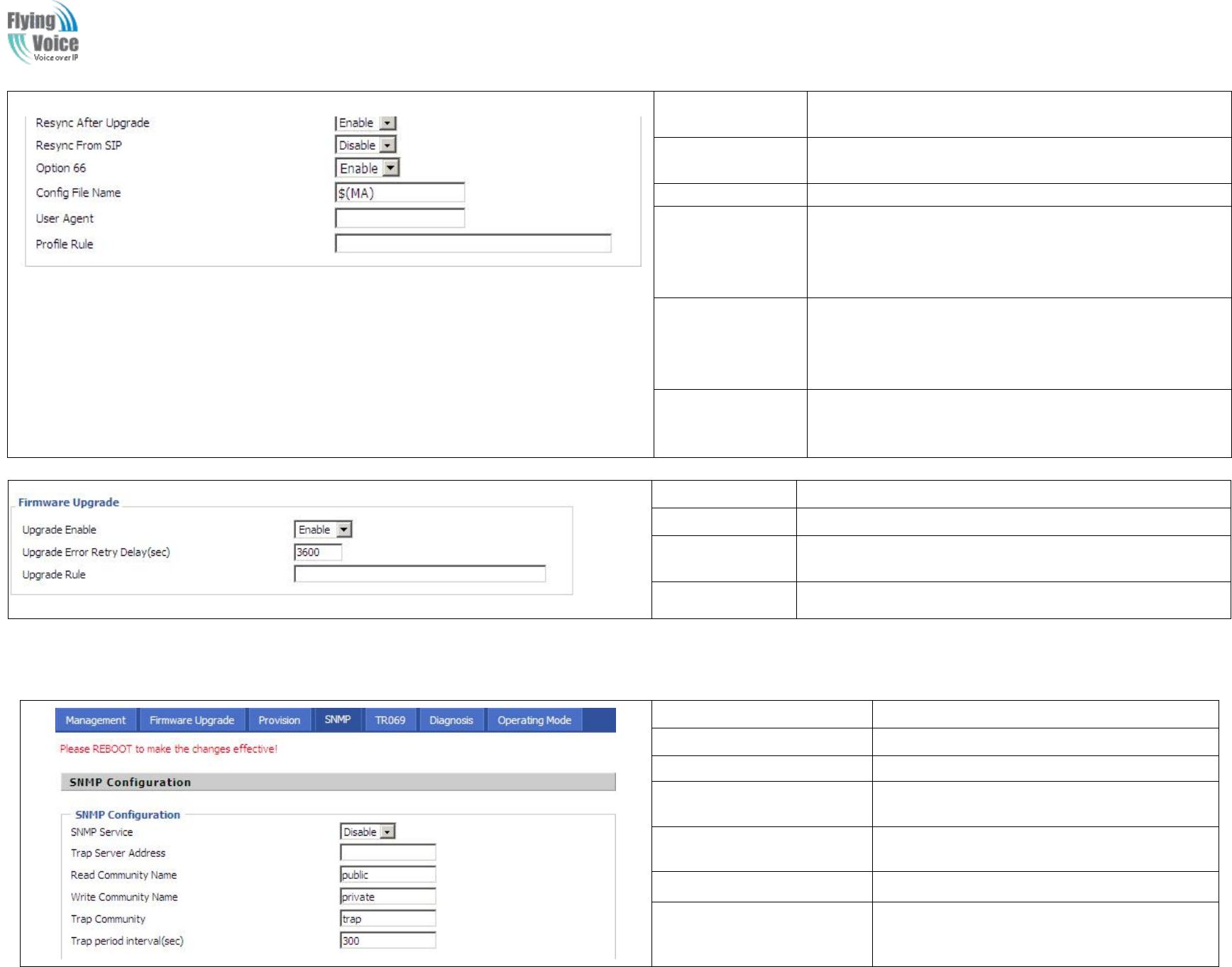
Copy Right 2017 All Rights Reserved by FLYINGVOICE TECHNOLOG LIMITED
V1.0
The page 70 of 78
Revision time: 2017-06-16 15:00
“Forced Resync Delay”, default is 14400s, when the time
over, FWR9202 will forced to resync.
Resync After
Upgrade
If or not enable firmware upgrade after resync, by default it
is enabled.
Resync From SIP
If or not enable resync from SIP.
Option 66
It is used for In-house provision mode only. When use
TFTP with option 66 to realize provisioning, user must
input right configuration file name in IP542N's webpage.
When disable Option 66, this parameter has no effect.
Config File Name
It is used for In-house provision mode only. When use
TFTP with option 66 to realize provisioning, user must
input right configuration file name in the webpage. When
disable Option 66, this parameter has no effect.
Profile Rule
URL of profile provision file
Note that the specified file path is relative to the TFTP
server’s virtual root directory.
Field Name
Description
Upgrade Enable
If or not enable firmware upgrade via provision.
Upgrade Error
Retry Delay(sec)
If the last upgrade fails, FWR9202 will try upgrading again
after “Upgrade Error Retry Delay” period, default is 3600s.
Upgrade Rule
URL of upgrade file
4.12.4 SNMP
Field Name
Description
SNMP Service
If or not enable SNMP.
Trap Server Address
Enter the trap server address.
Read Community Name
String, as an express password between
management progress and agent progress.
Write Community Name
String, as an express password between
management progress and agent progress.
Trap Community
The community field in trap.
Trap period interval(sec)
The interval of sending trap.
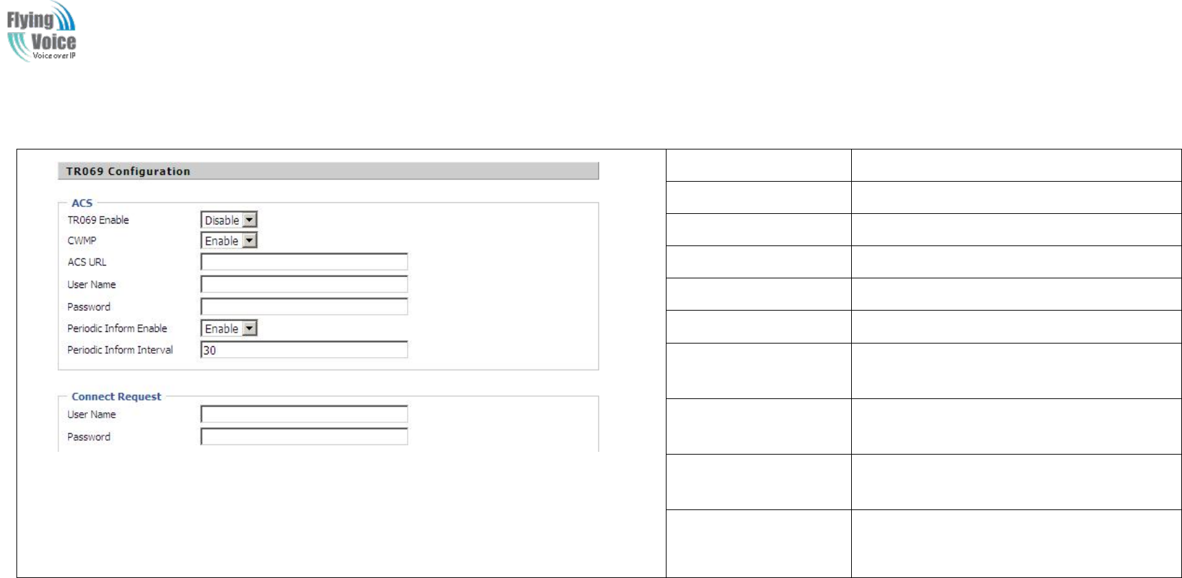
Copy Right 2017 All Rights Reserved by FLYINGVOICE TECHNOLOG LIMITED
V1.0
The page 71 of 78
Revision time: 2017-06-16 15:00
4.12.5 TR069
Field Name
Description
TR069 Enable
If or not enable TR069
CWMP
If or not enable CWMP
ACS URL
ACS URL address
User Name
ACS username
Password
ACS password
Periodic Inform Enable
If or not enable the function of periodic inform,
default is enable
Periodic Inform
Interval
Periodic notification interval, the unit is
seconds, default is 43200s
User Name
The username used to connect the TR069
server to the DUT.
Password
The password used to connect the TR069
server to the DUT.
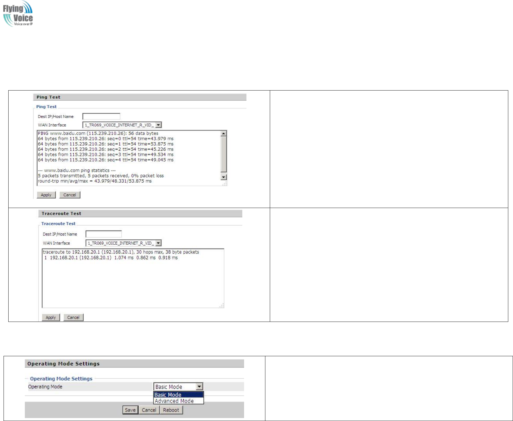
Copy Right 2017 All Rights Reserved by FLYINGVOICE TECHNOLOG LIMITED
V1.0
The page 72 of 78
Revision time: 2017-06-16 15:00
4.12.6 Diagnoisis
In
In this
this page,
page, user
user can
can do
do ping
ping test
test and
and traceroute
traceroute test
test to
to diagnose
diagnose the
the device
device’
’s
sconnection
connection status.
status.
1. Ping Test
Enter the destination IP or host name, and then click Apply, device will perform
ping test.
2. Traceroute Test
Enter the destination IP or host name, and then click Apply, device will perform
traceroute test.
4.12.7 Operation Mode
Choose the Operation Mode as Basic Mode or Advance Mode.
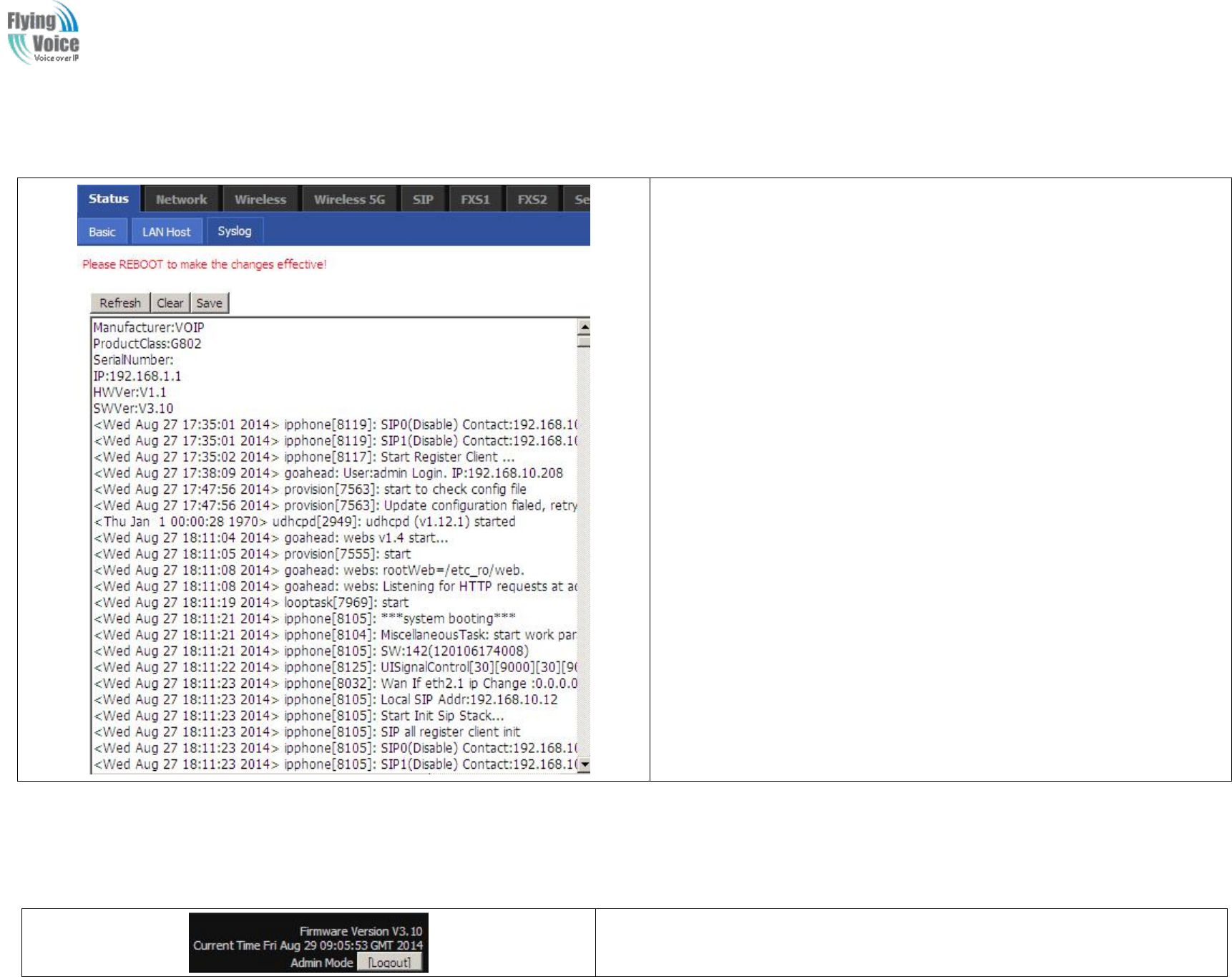
Copy Right 2017 All Rights Reserved by FLYINGVOICE TECHNOLOG LIMITED
V1.0
The page 73 of 78
Revision time: 2017-06-16 15:00
4.13 System Log
If you enable the system log in Status/syslog webpage, you can view the system
log in this webpage.
4.14 Logout
Press the logout button to logout, and then the login window will appear.

Copy Right 2017 All Rights Reserved by FLYINGVOICE TECHNOLOG LIMITED
V1.0
The page 74 of 78
Revision time: 2017-06-16 15:00
4.15 Reboot
Press
Press the
the button
button to
to reboot
reboot FWR9202
FWR9202.
.
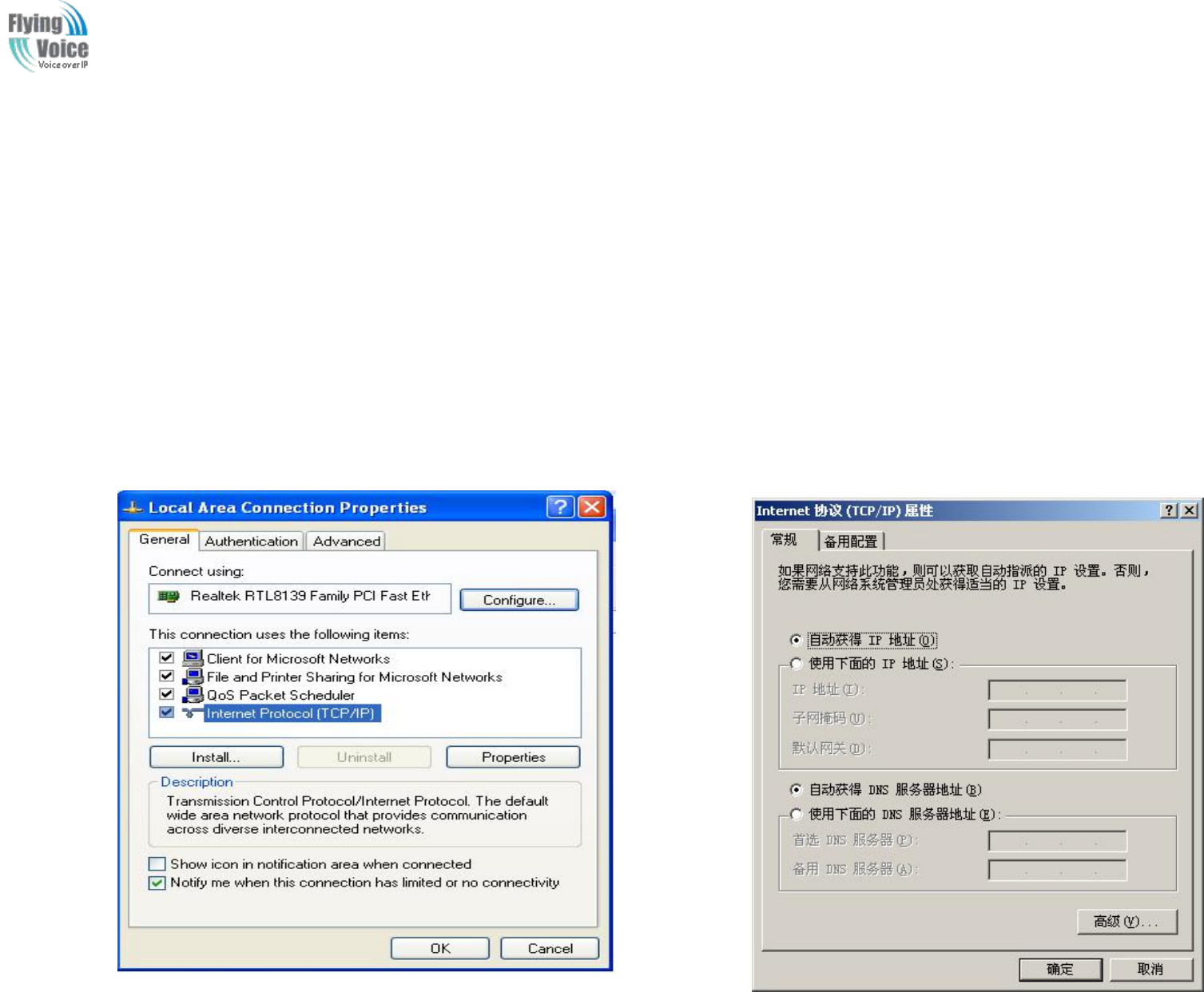
Copy Right 2017 All Rights Reserved by FLYINGVOICE TECHNOLOG LIMITED
V1.0
The page 75 of 78
Revision time: 2017-06-16 15:00
5Trouble shooting of the guide
5.1 Setting your PC gets IP automatically
Following
Following are
are the
the process
process of
of setting
setting your
your PC
PC gets
gets IP
IP automatically
automatically
Step
Step 1.
1.Click
Click the
the “
“begin
begin”
”
Step
Step 2.
2.Select
Select “
“control
control panel
panel”
”,
,then
then double
double click
click “
“network
network connections
connections”
”in
in the
the “
“control
control panel
panel”
”
Step
Step 3.
3.R
Right
ight clicks
clicks the
the “
“network
network connection
connection”
”that
that your
your PC
PC uses,
uses, select
select “
“attribute
attribute”
”and
and you
you can
can see
see the
the interface
interface as
as picture
picture 1
1:
:
Step
Step 4.
4.Select
Select “
“Internet
Internet Protocol
Protocol (TCP/IP)
(TCP/IP)”
”,
,click
click “
“attribute
attribute”
”button,
button, and
and you
you can
can see
see the
the interface
interface as
as following
following Picture
Picture 2
2and
and you
you should
should click
click the
the
“
“Get
Get IP
IP address
address automatically
automatically”
”.
.
Picture
Picture 1
1
Picture
Picture 2
2
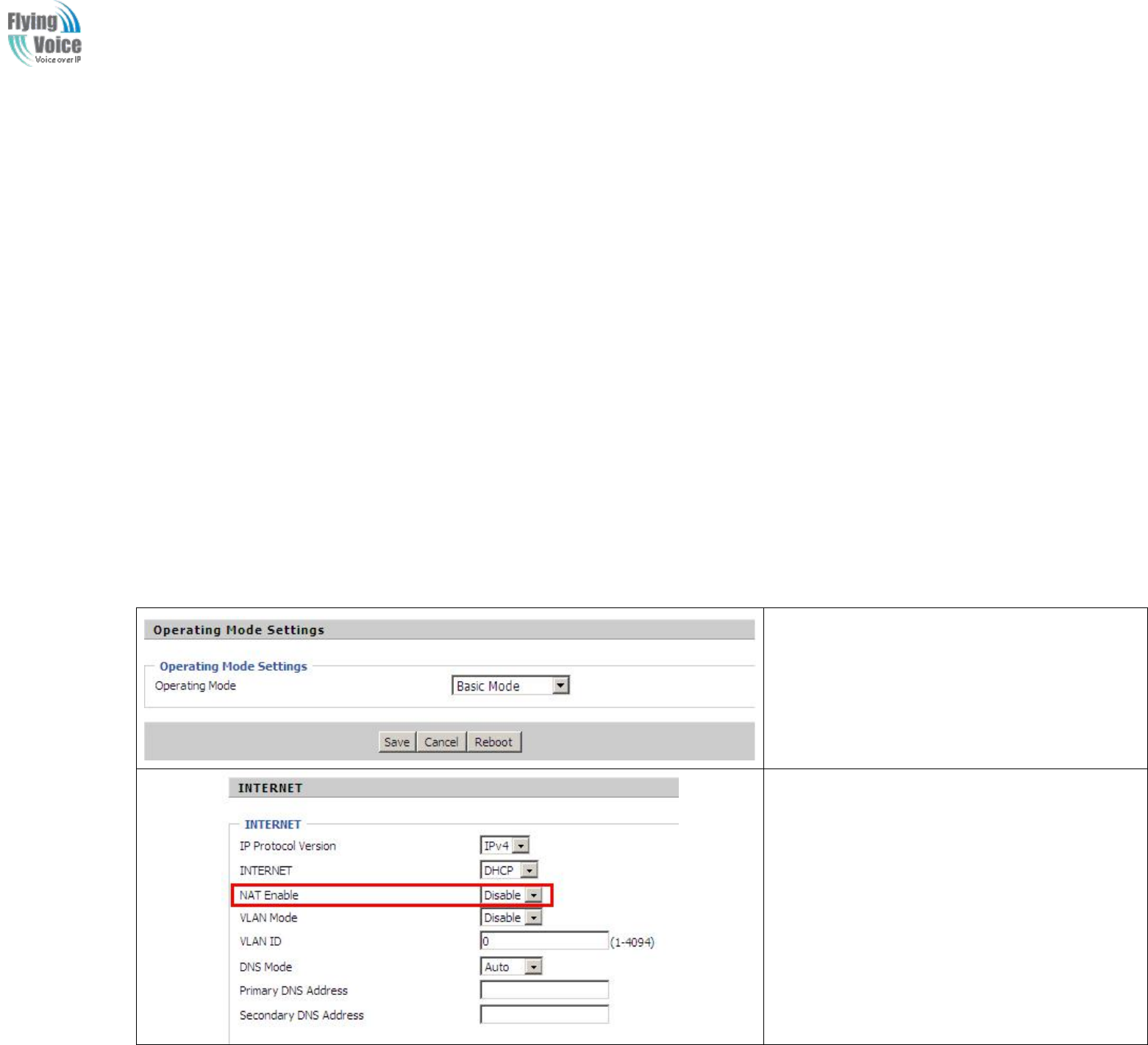
Copy Right 2017 All Rights Reserved by FLYINGVOICE TECHNOLOG LIMITED
V1.0
The page 76 of 78
Revision time: 2017-06-16 15:00
5.2 Can not connect to the configuration Website
Solution:
Solution:
Check
Check if
if the
the Ethernet
Ethernet cable
cable is
is properly
properly connected
connected,
,then
then
Check
Check if
if the
the URL
URL is
is right
right wrote,
wrote, the
the format
format of
of URL
URL is:
is: http://
http:// the
the IP
IP address
address:
:8080,
8080, 8080
8080 must
must be
be added,
added, then
then
Check
Check if
if the
the version
version of
of IE
IE is
is IE8
IE8,
,or
or use
use other
other browser
browser such
such as
as Firefox
Firefox or
or Mozilla
Mozilla,
,then
then
Contact
Contact your
your administrator,
administrator, supplier,
supplier, or
or ITSP
ITSP for
for more
more information
information or
or assistance.
assistance.
5.3 Forget the Password
If
If user
user changed
changed the
the password
password and
and then
then forgot,
forgot, you
you can
can not
not access
access to
to the
the configuration
configuration website.
website.
Solution:
Solution:
To
To factory
factory default:
default: press
press reset
reset button
button 10s.
10s.
5.4 Fast Bridge Setting
Step 1: Login WEB of Device.Turn to Page
Administration->Operating Mode. Set Operating
mode to Basic Mode. Save.
Step 2: Open Network->wan, Change Nat Enable to
Disable. Save and Reboot. Now Device works in
Bridge mode.
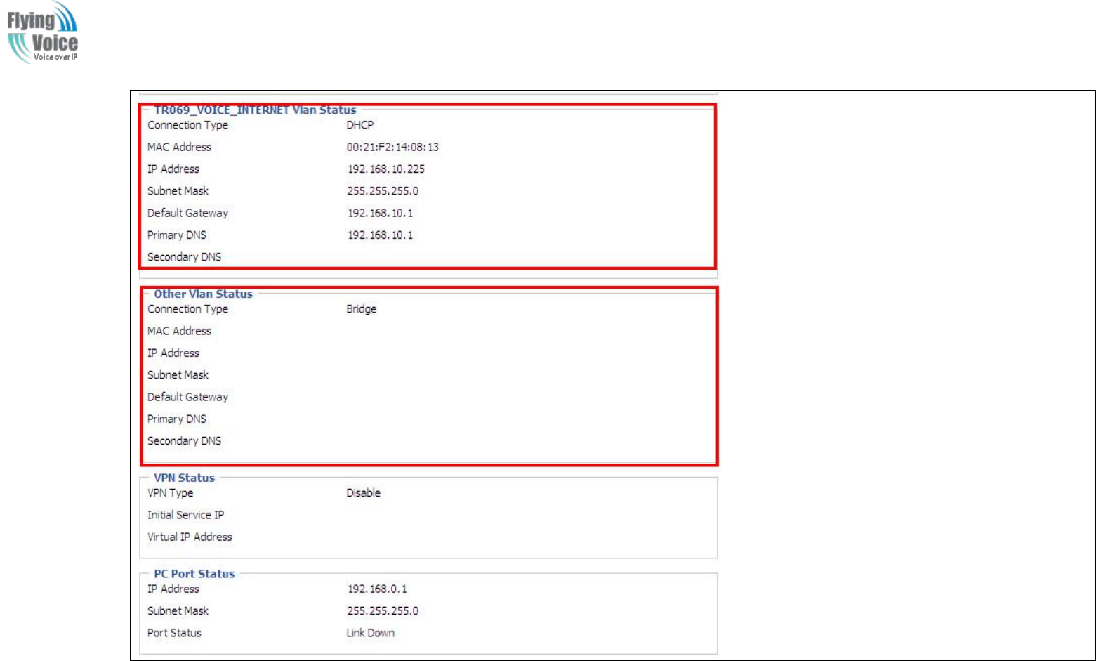
Copy Right 2017 All Rights Reserved by FLYINGVOICE TECHNOLOG LIMITED
V1.0
The page 77 of 78
Revision time: 2017-06-16 15:00
Step 3: Please Login from WAN port. Under is
example of Page Status->Basic.

Copy Right 2017 All Rights Reserved by FLYINGVOICE TECHNOLOG LIMITED
V1.0
The page 78 of 78
Revision time: 2017-06-16 15:00
Federal
Federal Communications
Communications Commission
Commission (FCC)
(FCC) Statement
Statement
This
This device
device complies
complies with
with part
part 15
15 of
of the
the FCC
FCC Rules.
Rules. Operation
Operation is
is subject
subject to
to the
the following
following two
two conditions:
conditions: (1)
(1) This
This device
device may
may not
not cause
cause harmful
harmful
interference,
interference, and
and (2)
(2) this
this device
device must
must accept
accept any
any interference
interference received,
received, including
including interference
interference that
that may
may cause
cause undesired
undesired operation.
operation.
Note:
Note: This
This equipment
equipment has
has been
been tested
tested and
and found
found to
to comply
comply with
with the
the limits
limits for
for a
aClass
Class B
Bdigital
digital device,
device, pursuant
pursuant to
to part
part 15
15 of
of the
the FCC
FCC Rules.
Rules.
These
These limits
limits are
are designed
designed to
to provide
provide reasonable
reasonable protection
protection against
against harmful
harmful interference
interference in
in a
aresidential
residential installation.
installation. This
This equipment
equipment generates,
generates,
uses
uses and
and can
can radiate
radiate radio
radio frequency
frequency energy
energy and,
and, if
if not
not installed
installed and
and used
used in
in accordance
accordance with
with the
the instructions,
instructions, may
may cause
cause harmful
harmful interference
interference
to
to radio
radio communications.
communications. However,
However, there
there is
is no
no guarantee
guarantee that
that interference
interference will
will not
not occur
occur in
in a
aparticular
particular installation.
installation. If
If this
this equipment
equipment does
does cause
cause
harmful
harmful interference
interference to
to radio
radio or
or television
television reception,
reception, which
which can
can be
be determined
determined by
by turning
turning the
the equipment
equipment off
off and
and on,
on, the
the user
user is
is encouraged
encouraged to
to try
try
to
to correct
correct the
the interference
interference by
by one
one or
or more
more of
of the
the following
following measures:
measures:
●
●Reorient
Reorient or
or relocate
relocate the
the receiving
receiving antenna.
antenna.
●
●Increase
Increase the
the separation
separation between
between the
the equipment
equipment and
and receiver.
receiver.
●
●Connect
Connect the
the equipment
equipment into
into an
an outlet
outlet on
on a
acircuit
circuit different
different from
from that
that to
to which
which the
the receiver
receiver is
is connected.
connected.
●
●Consult
Consult the
the dealer
dealer or
or an
an experienced
experienced radio/TV
radio/TV technician
technician for
for help.
help.
Warning:
Warning: Changes
Changes or
or modifications
modifications made
made to
to this
this device
device not
not expressly
expressly approved
approved by
by Flyingvoice
Flyingvoice Network
Network Technology
Technology Co.,
Co., Ltd
Ltd may
may void
void the
the FCC
FCC
authorization
authorization to
to operate
operate this
this device.
device.
Note:
Note: The
The manufacturer
manufacturer is
is not
not responsible
responsible for
for any
any radio
radio or
or TV
TV interference
interference caused
caused by
by unauthorized
unauthorized modifications
modifications to
to this
this equipment.
equipment. Such
Such
modifications
modifications could
could void
void the
the user
user’
’s
sauthority
authority to
to operate
operate the
the equipment.
equipment.
RF
RF exposure
exposure statement:
statement:
The
The transmitter
transmitter must
must not
not be
be colocated
colocated or
or operated
operated in
in conjunction
conjunction with
with any
any other
other antenna
antenna or
or transmitter.
transmitter. This
This equipment
equipment complies
complies with
with the
the FCC
FCC
RF
RF radiation
radiation exposure
exposure limits
limits set
set forth
forth for
for
an
an uncontrolled
uncontrolled environment.
environment. This
This equipment
equipment should
should be
be installed
installed and
and operated
operated with
with a
aminimum
minimum distance
distance of
of 20cm
20cm between
between the
the radiator
radiator and
and any
any
part
part of
of your
your body.
body.