Ford 2013 F 650 750 Owners Manual
2015-10-23
: Ford Ford-2013-Ford-F-650-750-Owners-Manual-815482 ford-2013-ford-f-650-750-owners-manual-815482 ford pdf
Open the PDF directly: View PDF ![]() .
.
Page Count: 378 [warning: Documents this large are best viewed by clicking the View PDF Link!]
- Temp.pdf
- Table of Contents
- Introduction
- Vehicle Inspection Guide
- Child Safety
- GENERAL INFORMATION
- CHILD SEATS
- CHILD SEAT POSITIONING
- BOOSTER SEATS
- INSTALLING CHILD SAFETY SEATS
- Using Automatic Locking Mode Combination Lap and Shoulder Belts (Front Passenger and Rear Outboard Seating Positions)
- Using Lower Anchors and Tethers for CHildren (LATCH)
- USING TETHER STRAPS
- Tether Strap Attachment
- Tether Strap Attachment (Rear SuperCab Only)
- CHILD SAFETY LOCKS (IF EQUIPPED)
- Safety Belts
- Keys and Remote Control
- Locks
- Steering Wheel
- Wipers and Washers
- Lighting
- Windows and Mirrors
- Instrument Cluster
- GAUGES - DIESEL ENGINE
- Engine Oil Pressure Gauge
- Engine Coolant Temperature Gauge
- Diesel Exhaust Fluid (DEF) Gauge
- Fuel Gauge
- Information Display
- GAUGES - GASOLINE ENGINE
- Engine Oil Pressure Gauge
- Engine Coolant Temperature Gauge
- Transmission Fluid Temperature Gauge
- Fuel Gauge
- Information Display
- WARNING LAMPS AND INDICATORS
- AUDIBLE WARNINGS AND INDICATORS
- Key In Ignition Warning Chime
- Headlamps On Warning Chime
- Information Displays
- Audio System
- GENERAL INFORMATION
- Radio Frequencies and Reception Factors
- CD and CD Player Information
- MP3 Track and Folder Structure
- AM/FM
- AM/FM/CD WITH SYNC®
- AUXILIARY INPUT JACK
- USB PORT (IF EQUIPPED)
- SATELLITE RADIO INFORMATION (IF EQUIPPED)
- Satellite Radio Channels
- Satellite Radio Reception Factors
- Sirius Satellite Radio Service
- Satellite Radio Electronic Serial Number (ESN)
- Troubleshooting
- Climate Control
- Seats
- SITTING IN THE CORRECT POSITION
- HEAD RESTRAINTS
- Front Seat Head Restraints
- Front Row Center, Outboard (Crew Cab), and Rear Seat Center (Crew Cab) Head Restraints
- Rear Head Restraints (SuperCab)
- MANUAL SEATS
- Moving the Seats Backward and Forward
- Recline Adjustment
- Tilting the Seat Back Forward (Two-passenger Bench Seat)
- Manual Lumbar (If Equipped)
- POWER SEATS
- Non Air-Ride Seat
- Air-Ride Seat
- REAR SEATS
- Folding Up the Rear Seats (SuperCab)
- Returning the Seat to the Seating Position
- Folding the Rear Seat Back (Crew Cab)
- REAR SEAT ARMREST (IF EQUIPPED)
- HEATED SEATS (IF EQUIPPED)
- FRONT SEAT ARMREST (IF EQUIPPED)
- Auxiliary Power Points
- Starting and Stopping the Engine
- Fuel and Refueling
- SAFETY PRECAUTIONS
- CHOOSING THE RIGHT FUEL
- Gasoline Engine
- Diesel Engine
- RUNNING OUT OF FUEL
- Gasoline Engine
- Diesel Engine
- REFUELING
- FUEL CONSUMPTION
- Filling the Tank
- Calculating Fuel Economy
- SELECTIVE CATALYTIC REDUCTION (SCR) SYSTEM (DIESEL ENGINE ONLY)
- Importance of Maintaining the DEF Level
- Warning Messages and Vehicle Operations
- Filling the DEF Tank
- Filling the DEF Tank in Cold Climates
- Contaminated DEF
- DEF Guidelines and Information
- NOISE EMISSIONS
- Transmission
- MANUAL TRANSMISSION OPERATION (IF EQUIPPED)
- Driving Hints
- Shifting with a Synchronized Transmission
- Shifting with a Non-Synchronized Transmission
- AUTOMATIC TRANSMISSION OPERATION (IF EQUIPPED)
- POWER TAKE-OFF (PTO) OPERATION (IF EQUIPPED)
- REAR AXLES
- Gross Axle Weight
- Locking or Limited-Slip Differentials
- Driver-controlled Differential Lock
- Fluid Temperature
- Axle Conversions
- TWO-SPEED REAR AXLE (IF EQUIPPED)
- Axle Shifting with a Manual Transmission
- Axle Shifting with an Automatic Transmission
- Split-shifting (Combined Axle and Transmission Shift) (Manual Transmission Only)
- Ratio Extender Use
- Brakes
- GENERAL INFORMATION
- If Brakes Do Not Grip Well
- Anti-lock Brake System (ABS)
- FULL POWER BRAKE SYSTEM
- AIR BRAKES
- Air Chamber Stroke Indication
- Cam Brakes - Automatic Slack Adjusters
- Emergency Air Brake
- HINTS ON DRIVING WITH ANTI-LOCK BRAKES
- EXHAUST BRAKE (IF EQUIPPED)
- Exhaust Brake Operating Characteristics
- TRAILER BRAKES
- Trailer Brake Hand Control (If Equipped)
- PARKING BRAKE
- Hydraulic Brakes
- Traction Control
- Cruise Control
- Driving Aids
- OPERATING YOUR VEHICLE
- General Information
- Backing Up
- Parking
- Cold Weather
- Hot Weather
- STEERING
- AIR SUSPENSION (IF EQUIPPED)
- Air Suspension Dump Switch
- System Indicator Light
- Connecting and Disconnecting a Trailer with Air Suspension and Air Suspension Dump Switch
- Suspension Conversions
- UPFITTER CONTROLS (IF EQUIPPED)
- Load Carrying
- Towing
- Driving Hints
- Roadside Emergencies
- ROADSIDE ASSISTANCE
- Vehicles Sold in the U.S.: Getting Roadside Assistance
- Vehicles Sold in the U.S.: Using Roadside Assistance
- Vehicles Sold in Canada: Getting Roadside Assistance
- Vehicles Sold Canada: Using Roadside Assistance
- HAZARD FLASHER CONTROL
- JUMP-STARTING THE VEHICLE
- Preparing Your Vehicle
- Connecting the Jumper Cables
- Jump Starting
- Removing the Jumper Cables
- Customer Assistance
- Fuses
- Maintenance
- GENERAL INFORMATION
- Servicing Guidelines
- OPENING AND CLOSING THE HOOD
- ENGINE OIL DIPSTICK
- Diesel Engine
- Gasoline Engine
- ENGINE OIL CHECK
- ENGINE COOLANT CHECK
- TRANSMISSION FLUID CHECK
- Allison Automatic Transmissions
- DRIVESHAFT
- REAR AXLE FLUID
- Checking the Fluid Level
- Changing the Fluid
- SPRING U-BOLT CHECKS
- U-bolt Nut Torque
- Air Suspension U-bolt Checks and Re-torquing Procedures
- Air Suspension U-bolt and U-bolt Nut Installation
- BRAKE FLUID CHECK
- CLUTCH FLUID AND LINKAGE
- Clutch Fluid
- Clutch Linkage
- POWER STEERING FLUID CHECK
- FUEL FILTER
- Gasoline Engine
- Diesel Engine
- WASHER FLUID CHECK
- CHANGING THE VEHICLE BATTERY
- CHECKING THE WIPER BLADES
- CHANGING THE WIPER BLADES
- AIR FILTER CHECK
- Diesel Engine
- Gasoline Engine
- ADJUSTING THE HEADLAMPS
- CHANGING A BULB
- Lamp Assembly Condensation
- Replacing Headlamp Bulbs
- Replacing Front Parking/Turn Signal/Side Marker Lamp Bulbs
- Replacing Front Clearance and Identification Lamp Bulbs
- Replacing Brake/Tail/Rear Turn Signal/Reverse/License Plate Lamp Bulbs
- BULB SPECIFICATION CHART
- Vehicle Care
- GENERAL INFORMATION
- CLEANING PRODUCTS
- CLEANING THE EXTERIOR
- Underbody
- WAXING
- REPAIRING MINOR PAINT DAMAGE
- CLEANING THE ENGINE
- CLEANING THE WINDOWS AND WIPER BLADES
- CLEANING THE INTERIOR
- CLEANING THE INSTRUMENT PANEL AND INSTRUMENT CLUSTER LENS
- CLEANING LEATHER SEATS
- CLEANING THE ALLOY WHEELS
- VEHICLE STORAGE
- General
- Body
- Engine
- Fuel System
- Cooling System
- Battery
- Brakes
- Tires
- Miscellaneous
- Removing Your Vehicle from Storage
- Wheels and Tires
- Capacities and Specifications
- ENGINE SPECIFICATIONS (GASOLINE ENGINE ONLY)
- Engine Drivebelt Routing
- TECHNICAL SPECIFICATIONS
- REFILL CAPACITIES
- Engine Coolant and Engine Oil
- Transmission
- Rear Axle
- Power Steering
- Air Conditioner Refrigerant
- Fuel Tanks
- MOTORCRAFT® PART NUMBERS
- VEHICLE IDENTIFICATION NUMBER
- VEHICLE CERTIFICATION LABEL
- TRANSMISSION CODE DESIGNATION
- Scheduled Maintenance
- SYNC®
- GENERAL INFORMATION
- USING VOICE RECOGNITION
- USING SYNC WITH YOUR PHONE
- SYNC APPLICATIONS AND SERVICES (IF EQUIPPED)
- USING SYNC WITH YOUR MEDIA PLAYER
- TROUBLESHOOTING
- Appendices
- Index
DC4J 19A321 AA | April 2013 | Second Printing | Owner’s Manual | F-650/750 | Litho in U.S.A.
2013 F-650/750 Owner’s Manual
fordowner.com ford.ca
2013 F-650/750 Owner’s Manual

Introduction 7
Vehicle Inspection Guide 14
Child Safety 26
Child seats...........................................28
Child seat positioning ...................................28
Booster seats .........................................30
Installing child safety seats ...............................33
Child safety locks ......................................40
Safety Belts 41
Fastening the safety belts ................................42
Safety belt height adjustment .............................47
Safetybeltwarninglightandindicatorchime..................48
Safety belt-minder .....................................49
Child restraint and safety belt maintenance ...................51
Keys and Remote Control 52
Keys ...............................................52
Locks 53
Locking and unlocking ..................................53
Steering Wheel 54
Adjusting the steering wheel ..............................54
Steering wheel controls .................................54
Wipers and Washers 55
Windshield wipers .....................................55
Windshield washers ....................................55
Lighting 56
Lighting control .......................................56
Instrument lighting dimmer...............................57
Daytime running lamps ..................................57
Turn signal control .....................................58
Interior lamps ........................................58
Table of Contents 1
2013 F-650/750 (f67)
Owners Guide gf, 2nd Printing, March 2013
USA (fus)

Windows and Mirrors 59
Power windows .......................................59
Exteriormirrors.......................................60
Instrument Cluster 64
Gauges .............................................64
Warning lamps and indicators .............................68
Audible warnings and indicators ...........................73
Information Displays 74
Message center .......................................74
Information messages ...................................76
Audio System 77
AM/FMstereo ........................................79
AM/FM/CD with SYNC ..................................80
Auxiliary input jack ....................................82
USB port ............................................84
Satellite radio information................................84
Climate Control 88
Manual heating and air conditioning ........................88
Seats 91
Sitting in the correct position .............................91
Head restraints........................................92
Manual seats .........................................94
Power seats ..........................................96
Rear seats ...........................................98
Heated seats .........................................99
Auxiliary Power Points 101
Starting and Stopping the Engine 102
Ignition switch .......................................103
Engine block heater ...................................111
2Table of Contents
2013 F-650/750 (f67)
Owners Guide gf, 2nd Printing, March 2013
USA (fus)

Fuel and Refueling 113
Fuel quality .........................................114
Running out of fuel....................................116
Refueling...........................................117
Fuel consumption .....................................118
Diesel Exhaust Fluid (DEF) .............................120
Transmission 132
Transmission operation .................................136
Brakes 147
Brakes .............................................147
Hints on driving with anti-lock brakes ......................151
Traction Control 164
TractionControl™....................................164
Cruise Control 166
Using cruise control ...................................166
Driving Aids 168
Steering ............................................170
Air suspension .......................................171
Upfitter controls ......................................172
Load Carrying 173
Vehicle loading .......................................174
Towing 175
Trailertowing........................................175
Wrecker towing ......................................179
Driving Hints 182
Economical driving ....................................182
Table of Contents 3
2013 F-650/750 (f67)
Owners Guide gf, 2nd Printing, March 2013
USA (fus)

Roadside Emergencies 184
Getting roadside assistance ..............................184
Hazard flasher control..................................185
Jump-starting the vehicle ...............................185
Customer Assistance 189
Getting assistance outside the U.S. and Canada ...............191
Reporting safety defects (U.S. only) .......................193
Reporting safety defects (Canada only) .....................193
Fuses 194
Changing a fuse ......................................194
Fuse specification chart ................................195
Fuses and relays......................................203
Maintenance 204
General information ...................................204
Opening and closing the hood ............................215
Engine oil dipstick ....................................217
Engine oil check......................................218
Engine coolant check ..................................219
Automatic transmission fluid check ........................223
Brake fluid check .....................................229
Power steering fluid check ..............................231
Fuel filter...........................................232
Washer fluid check ....................................232
Changing the vehicle battery .............................233
Checking the wiper blades ..............................235
Changing the wiper blades ..............................236
Air filter(s) .........................................236
Adjusting the headlamps ................................239
Changing a bulb ......................................239
Bulb specification chart.................................241
4Table of Contents
2013 F-650/750 (f67)
Owners Guide gf, 2nd Printing, March 2013
USA (fus)

Vehicle Care 242
Cleaning products.....................................242
Cleaning the exterior ..................................242
Waxing.............................................244
Repairing minor paint damage ............................245
Cleaning the engine ...................................245
Cleaning the windows and wiper blades .....................245
Cleaning the interior ...................................246
Cleaning the instrument panel and instrument cluster lens .......247
Cleaning leather seats ..................................248
Cleaning the alloy wheels ...............................248
Vehiclestorage.......................................249
Wheels and Tires 252
Tire information ......................................252
Wheel lug nut torque ..................................262
Capacities and Specifications 263
Engine drivebelt ......................................263
Lubricant specifications.................................264
Refill capacities ......................................277
Part numbers ........................................280
Vehicle identification number ............................281
Vehicle certification label ...............................281
Scheduled Maintenance 283
Table of Contents 5
2013 F-650/750 (f67)
Owners Guide gf, 2nd Printing, March 2013
USA (fus)

SYNC® 319
Pairing your phone for the first time .......................324
911 Assist™ .........................................338
Vehicle Health Report ..................................341
Appendices 364
Index 372
The information contained in this publication was correct at the time of going to
print. In the interest of continuous development, we reserve the right to change
specifications, design or equipment at any time without notice or obligation. No
part of this publication may be reproduced, transmitted, stored in a retrieval
system or translated into any language in any form by any means without our
written permission. Errors and omissions excepted.
© Ford Motor Company 2013
6Table of Contents
2013 F-650/750 (f67)
Owners Guide gf, 2nd Printing, March 2013
USA (fus)
ABOUT THIS MANUAL
Thank you for choosing Ford. We recommend that you take some time to
get to know your vehicle by reading this manual. The more that you
know about it, the greater the safety and pleasure you will get from
driving it.
WARNING: Always drive with due care and attention when
using and operating the controls and features on your vehicle.
Note: This manual describes a range of product features and options,
sometimes before they are generally available. Therefore, you may find
options in this manual that are not found on your vehicle.
Note: Some of the illustrations in this manual may be used for different
models, so they may appear different than your vehicle. However, the
essential information in the illustrations is always correct.
Note: Always use and operate your vehicle in line with all applicable
laws and regulations.
Note: Pass on this manual when selling your vehicle. It is an integral
part of the vehicle.
This manual may qualify the location of a component as left-hand side or
right-hand side. The side is determined when facing forward in the seat.
A. Right-hand side
B. Left-hand side
Protecting the Environment
You must play your part in protecting the environment. Correct
vehicle usage and the authorized disposal of waste, cleaning
and lubrication materials are significant steps toward this aim.
A
B
Introduction 7
2013 F-650/750 (f67)
Owners Guide gf, 2nd Printing, March 2013
USA (fus)

SYMBOL GLOSSARY
WARNING: You risk death or serious injury to yourself and
others if you do not follow the instruction highlighted by the
warning symbol.
These are some of the symbols you may see on your vehicle.
Symbol Description Symbol Description Symbol Description
Safety alert See Owner’s
Manual
Anti-lock
braking
system
Avoid
smoking,
flames, or
sparks
Battery Battery acid
Brake fluid –
non
petroleum
base
Brake system Cabin air
filter
Check fuel
cap
Child Safety
Door Lock
and Unlock
Child seat
lower anchor
Child seat
tether anchor
Cruise
control
Do not open
when hot
Engine air
filter
Engine
coolant
Engine
coolant
temperature
Engine oil Explosive gas Fan warning
Fasten safety
belt
Front airbag Front fog
lamps
8Introduction
2013 F-650/750 (f67)
Owners Guide gf, 2nd Printing, March 2013
USA (fus)
Symbol Description Symbol Description Symbol Description
Fuel pump
reset
Fuse
compartment
Hazard
warning
flasher
Heated rear
window
Interior
luggage
compartment
release
Jack
Lighting
control
Low tire
pressure
warning
Maintain
correct fluid
level
Panic alarm Parking aid
system
Parking
brake system
Power
steering fluid
Power
windows
front and
rear
Power
window
lockout
Service
engine soon
Side airbag Stability
control
Windshield
defrost and
demist
Windshield
washer and
wiper
Introduction 9
2013 F-650/750 (f67)
Owners Guide gf, 2nd Printing, March 2013
USA (fus)

DATA RECORDING
Service Data Recording
Service data recorders in your vehicle are capable of collecting and
storing diagnostic information about your vehicle. This potentially
includes information about the performance or status of various systems
and modules in the vehicle, such as engine, throttle, steering or brake
systems. In order to properly diagnose and service your vehicle, Ford
Motor Company, Ford of Canada, and service and repair facilities may
access or share among them vehicle diagnostic information received
through a direct connection to your vehicle when diagnosing or servicing
your vehicle. Additionally, when your vehicle is in for service or repair,
Ford Motor Company, Ford of Canada, and service and repair facilities
may access or share among them data for vehicle improvement purposes.
For U.S. only (if equipped), if you choose to use the SYNC® Vehicle
Health Report, you consent that certain diagnostic information may also
be accessed electronically by Ford Motor Company and Ford authorized
service facilities, and that the diagnostic information may be used for any
purpose. See the SYNC® chapter for more information.
CALIFORNIA PROPOSITION 65
WARNING: Some constituents of engine exhaust, certain vehicle
components, certain fluids contained in vehicles and certain
products of component wear contain or emit chemicals known to the
State of California to cause cancer and birth defects or other
reproductive harm.
PERCHLORATE MATERIAL
Note: Certain components in your vehicle, such as airbag modules,
safety belt pretensioners, and remote control batteries, may contain
perchlorate material. Special handling may apply for service or vehicle
end of life disposal. See www.dtsc.ca.gov/hazardouswaste/perchlorate for
more information.
10 Introduction
2013 F-650/750 (f67)
Owners Guide gf, 2nd Printing, March 2013
USA (fus)

FORD CREDIT (U.S. ONLY)
Ford Credit offers a full range of financing and lease plans to help you
acquire your vehicle. If you have financed or leased your vehicle through
Ford Credit, thank you for your business.
For your convenience, we offer a number of ways to contact us, as well
as help manage your account.
Phone: 1-800-727-7000
For more information regarding Ford Credit, as well as access to
Account Manager, please go to www.fordcredit.com.
REPLACEMENT PARTS RECOMMENDATION
Your vehicle has been built to the highest standards using quality parts.
We recommend that you demand the use of genuine Ford and Motorcraft
parts whenever your vehicle requires scheduled maintenance or repair.
You can clearly identify genuine Ford and Motorcraft parts by looking for
the Ford, FoMoCo or Motorcraft branding on the parts or their
packaging.
Scheduled Maintenance and Mechanical Repairs
One of the best ways for you to make sure that your vehicle provides
years of service is to have it maintained in line with our
recommendations using parts that conform to the specifications detailed
in this owner’s manual. Genuine Ford and Motorcraft parts meet or
exceed these specifications.
Collision Repairs
We hope that you never experience a collision, but accidents do happen.
Genuine Ford replacement collision parts meet our stringent
requirements for fit, finish, structural integrity, corrosion protection and
dent resistance. During vehicle development, we validate that these parts
deliver the intended level of protection as a whole system. A great way
to know for sure you are getting this level of protection is to use genuine
Ford replacement collision parts.
Warranty on Replacement Parts
Genuine Ford and Motorcraft replacement parts are the only
replacement parts that benefit from a Ford Warranty. Damage caused to
your vehicle as a result of the failure of non-Ford parts may not be
covered by the Ford Warranty. For additional information, see the terms
and conditions of the Ford Warranty.
Introduction 11
2013 F-650/750 (f67)
Owners Guide gf, 2nd Printing, March 2013
USA (fus)

SPECIAL NOTICES
New Vehicle Limited Warranty
For a detailed description of what is covered and what is not covered by
your vehicle’s New Vehicle Limited Warranty, see the warranty
information that is provided to you along with your owner’s manual.
Special Instructions
For your added safety, your vehicle is fitted with sophisticated electronic
controls.
MOBILE COMMUNICATIONS EQUIPMENT
Using mobile communications equipment is becoming increasingly
important in the conduct of business and personal affairs. However, you
must not compromise your own or others’ safety when using such
equipment. Mobile communications can enhance personal safety and
security when appropriately used, particularly in emergency situations.
Safety must be paramount when using mobile communications
equipment to avoid negating these benefits.
Mobile communication equipment includes, but is not limited to, cellular
phones, pagers, portable email devices, text messaging devices and
portable two-way radios.
WARNING: Driving while distracted can result in loss of vehicle
control, crash and injury. We strongly recommend that you use
extreme caution when using any device that may take your focus off
the road. Your primary responsibility is the safe operation of your
vehicle. We recommend against the use of any handheld device while
driving and encourage the use of voice-operated systems when possible.
Make sure you are aware of all applicable local laws that may affect the
use of electronic devices while driving.
12 Introduction
2013 F-650/750 (f67)
Owners Guide gf, 2nd Printing, March 2013
USA (fus)

FEDERAL HIGHWAY ADMINISTRATION REGULATION
Regulations such as those issued by the Federal Highway Administration
or issued pursuant to the Occupational Safety and Health Act (OSHA),
and state and local laws and regulations may require additional equipment
for the way you intend to use the vehicle. It is the responsibility of the
registered owner to determine the applicability of such laws and
regulations to your intended use for the vehicle, and to arrange for the
installation of required equipment. Your dealer has information about the
availability of equipment which may be ordered for your vehicle.
ENTERING, EXITING OR CLIMBING ON THIS VEHICLE
WARNING: Do not carry items while entering, exiting or
climbing. Make sure you keep a firm grip. Always FACE the
VEHICLE STEP and HANDLE SYSTEM while climbing up and down.
Do not climb behind the cab unless you have three point contact with a
step and handle system at all times.
You must be careful and deliberate to minimize the possibility of personal
injury from a slip and fall when entering, exiting or climbing on this
vehicle. Always use the steps and assist handles before climbing. Do not
skip any steps or assist handles. Use three point contact at all times with
at least two feet and one hand or two hands and one foot firmly placed
during all phases of entering, exiting or climbing. Always keep your shoe
soles and hands clean. Keep the steps and assist handles free of snow,
ice, oil, grease, substances or debris. Be sure to use extra care in bad
weather. Avoid wearing thick gloves. Always perform trailer hook-up
while standing on the ground.
Introduction 13
2013 F-650/750 (f67)
Owners Guide gf, 2nd Printing, March 2013
USA (fus)

VEHICLE INSPECTION INFORMATION
To be sure your vehicle is ready to operate, conduct a pre-trip inspection
at the beginning of each work period. Follow the steps listed in this
section to ensure a proper vehicle inspection procedure. The pages in
this section may be produced locally and used on a regular basis.
WARNING: Exercise great caution when working on a vehicle
equipped with an automatic fan clutch. The fan starts in motion
only after the engine coolant reaches a predetermined temperature or
the refrigerant pressure (if equipped with air conditioning) reaches a
predetermined setting. The fan starts at this point with no advance
warning. Never reach near, or permit objects to protrude into, the fan
blade radius while the engine is running as this could result in vehicle
damage, personal injury or death.
WARNING: Do not operate the vehicle if any suspension
conditions listed in the following charts are evident. Loss of
steering or suspension could result in property damage, personal injury
or death.
WARNING: If a wheel must be changed, obtain expert tire
service help. Mounting and un-mounting of tires should only be
performed by a qualified technician using necessary safety procedures
and equipment, otherwise the result could be property damage,
personal injury or death.
Note: Always make sure the parking brake is applied before starting the
engine.
14 Vehicle Inspection Guide
2013 F-650/750 (f67)
Owners Guide gf, 2nd Printing, March 2013
USA (fus)

Engine Compartment (with Engine Stopped)
Engine Oil Use the dipstick to verify the oil level is in the
proper operating range. See Engine oil check in
the Maintenance chapter.
Engine Coolant Look through the plastic reservoir or the clear
sight glass on the reservoir (depending upon
vehicle equipment) and verify the coolant level is
within the proper operating range. Do not
remove the pressure cap until the coolant
has cooled. See Engine coolant check in the
Maintenance chapter.
Power Steering
Fluid
Verify that the fluid level is in the proper
operating range. See Power steering fluid check
in the Maintenance chapter.
Brake Fluid Remove the master cylinder caps and inspect the
fluid level. See Brake fluid check in the
Maintenance chapter.
Clutch Fluid Remove the cap and inspect the fluid level. See
Clutch fluid and linkage in the Maintenance
chapter.
Belts (Fan,
Alternator, Water
Pump and A/C
Compressor)
Inspect for glazing, fraying or cracking. There
should be no more than 5-7 cracks per rib, per
inch (2.5 cm).
Fluid Leaks Inspect for signs of fluid puddles or dripping fluid
on the ground under the engine, or the underside
of the engine.
HVAC Air Inlet Inspect for debris that may have collected on the
HVAC air inlet grille or inside the exterior module
as this may reduce system performance.
Vehicle Inspection Guide 15
2013 F-650/750 (f67)
Owners Guide gf, 2nd Printing, March 2013
USA (fus)

Engine Starting (Parking Brake Applied)
Safety and
Emergency
Equipment
•Before entering the cab, verify that the vehicle
is equipped with spare electrical fuses (if used),
three red reflective triangles, a properly charged
and rated fire extinguisher and wheel chocks.
•Walk around the vehicle and verify all steps
and grab handles, inside and out (as well as
behind), are tight and clean. Use extreme caution
and a three-point stance at all times.
•Inspect door latches for proper closing,
latching and locking.
Starting the
Engine
Set the parking brake. If starting a vehicle with a
manual transmission, press the clutch and verify
the transmission is in neutral. If starting a vehicle
with an automatic transmission, make sure the
gearshift lever is in position Nor P(if equipped
with a park position).
Diesel engine: Turn the key to the on position.
Turn the key to start when the wait to start
indicator light in the instrument cluster turns off.
Gasoline engine: Turn the key to start, then
release it as soon as the engine starts.
Engine Oil
Pressure
Verify pressure builds to normal operating range.
Air Chime (If
Equipped with an
Air Compressor)
The low air pressure warning chime should sound
immediately after the engine starts but before the
compressor has built-up pressure. The chime
should stop when the air pressure reaches 70 psi
(483 kPa) (or more). Let the air pressure build
to governed cut-out pressure, which should occur
between 115–130 psi (793–896 kPa).
Accelerator Press the accelerator and verify that it operates
smoothly, without any binding or irregular feel.
Release the pedal and verify the engine returns
to idle speed immediately.
16 Vehicle Inspection Guide
2013 F-650/750 (f67)
Owners Guide gf, 2nd Printing, March 2013
USA (fus)

Engine Starting (Parking Brake Applied)
Voltmeter Check the gauge (diesel engine) or indicator light
(gasoline engine) to verify the alternator is
charging.
Steering Linkage
Free Play
Inspect for excessive free play in the steering
linkages. The steering wheel should have less
than 2 in. (5 cm) of free play at its rim.
Full Power
Hydraulic Brake
Inspection
Pump the brake pedal several times with the
ignition in the off or run position. The
motor/pumps can be heard momentarily
replenishing the accumulators.
Parking Brake Verify the parking brake holds the vehicle by
gently trying to pull forward with the parking
brake applied.
Vehicle Inspection Guide 17
2013 F-650/750 (f67)
Owners Guide gf, 2nd Printing, March 2013
USA (fus)

Engine Starting (Parking Brake Applied)
Air Brakes Verify operation using the following procedure.
Chock the wheels, if necessary. Push in the
parking brake and, on tractors, push in the
tractor parking brake knob:
1. Verify the air compressor or governor cut-out
pressure is approximately 120 psi (827 kPa).
2. Turn off the engine, then turn the key back to
the on position (without starting the engine).
3. Without the brake pedal applied, note the air
pressure drop for one minute. It should be less
than 2 psi (14 kPa) for single vehicles and 3 psi
(21 kPa) for combination vehicles.
4. Press and hold the brake pedal with 90 psi
(621 kPa) or more. Make sure there is no more
than a 3 psi (21 kPa) per minute leak for single
vehicles and a 4 psi (28 kPa) per minute leak for
combination vehicles.
5. Pump the brake pedal to deplete the system of
air pressure. The warning light and chime should
activate at 57 psi (393 kPa).
6. Pump the brake pedal and make sure the
parking brake and trailer parking brake knobs
pop out at 20 psi (138 kPa) or higher.
Automatic
Transmission
Fluid
Verify that the fluid level is in the proper
operating range. See Transmission fluid check
in the Maintenance chapter.
18 Vehicle Inspection Guide
2013 F-650/750 (f67)
Owners Guide gf, 2nd Printing, March 2013
USA (fus)

Front of Vehicle
Lights Verify:
•all exterior lights illuminate and are clean
•headlights function on high and low beam
•reflectors are clean, unbroken and of proper
color (red on rear, amber elsewhere)
•running lights are clean and unbroken.
Steering Gear Inspect for:
•missing or loose fasteners
•power steering fluid leaks
•damage to power steering hoses.
Steering Linkage Verify:
•connecting links, arms and rods are not worn
or cracked
•joints, sockets and boot seals are not worn or
loose
•cotter keys, nuts and bolts are not loose or
missing.
Tow Hooks Inspect front and rear tow hooks for damage or
loose mounting. This is particularly important on
vehicles when they are used frequently.
Vehicle Inspection Guide 19
2013 F-650/750 (f67)
Owners Guide gf, 2nd Printing, March 2013
USA (fus)

Front Suspension
Springs Inspect for leaves that may be:
•missing
•broken
•shifted
•in contact with (or nearly contacting) a tire,
rim, brake drum, frame or body component.
Note: Never apply grease to spring pads.
Spring Mounts Inspect the following for cracks, breaks, wear,
damage and tightness:
•spring hangers
•bolts
•bushings
•axle mounting bolts
•nuts.
Shock Absorbers Inspect for:
•cracks
•leaks
•missing or broken bolts or bushings.
Front Brakes
Hoses •Inspect for cracked, worn or frayed hoses.
•Verify all couplings are secured.
Brake Chambers Verify:
•there are no cracks or dents
•they are securely mounted.
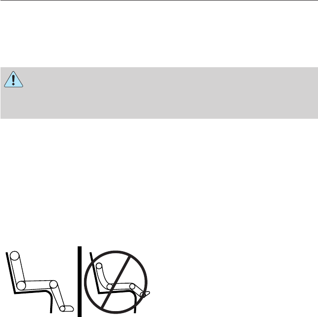
Slack Adjusters Inspect for broken, loose or missing parts.
Note: The angle between the push rod and
adjuster arm should be approximately 90° when
the brakes are applied. When pulled by hand,
the push rod should not move more than
approximately one inch (2.5 cm).
Drums Verify:
•there are no cracks, dents, holes, and no loose
or missing bolts
•the brake linings are not worn, dangerously
thin or contaminated by lubricant.
20 Vehicle Inspection Guide
2013 F-650/750 (f67)
Owners Guide gf, 2nd Printing, March 2013
USA (fus)

Front Wheels
Rims Inspect for damaged or bent rims. They should
not have welding repairs, and there should be no
rust trails that indicate it is loose on the wheel.
Lug Nuts Verify all lug nuts are present and not loose (look
for rust trails around the lug nuts). There should
be no cracks radiating from the lug bolt holes or
distortion of the bolt holes.
Hub Oil Seals Inspect wheel hub oil seal for leaks and, if sight
glass if present, verify the oil level is adequate.
Oil-lubricated
Front Wheel
Bearings
Inspect for proper lubrication level if the hubcap
has a transparent window. If the hubcap does not
have a transparent window, remove the rubber
fill-plug and inspect for proper level.
Fuel Area
Fuel Tank(s) Verify:
•tank(s) and cap(s) are secure
•there is no damage to the tank(s).
Leaks Inspect for leaks from the tank(s).
Diesel Exhaust Fluid (DEF) Area
DEF Tanks Verify:
•tanks and caps are secure
•there is no damage to the tanks.
Leaks Inspect for leaks from the tanks.
Underbody
Driveshaft Verify:
•the driveshaft is not bent or cracked
•all driveshaft couplings are secure.
Exhaust System Verify:
•the visible outside parts are securely mounted
•there are no cracks, holes or severe dents.
Frame •Inspect for cracks or bends in longitudinal
frame members.
•Verify there are no loose, cracked, bent, broken
or missing crossmembers or crossmember
fasteners.
Vehicle Inspection Guide 21
2013 F-650/750 (f67)
Owners Guide gf, 2nd Printing, March 2013
USA (fus)

Rear of Vehicle
Air Hoses and
Electrical Lines
•Verify air hoses and electrical line insulation
are not cut, cracked, chafed or worn. Listen for
audible air leaks.
•Verify air and electrical lines are not tangled,
crimped or pinched or being dragged against any
truck parts. None of the air or electrical line
should be spliced or taped.
•Inspect for corrosion on pins and in electrical
sockets to ensure continuity and reduced heat
build-up potential.
Deck Plate Verify deck plate is clean, securely bolted to the
frame and clear of loose objects.
Turns Signals,
Brake Lights and
Flashers
Verify:
•both brake lights illuminate when the pedal is
applied
•each signal flashes
•four-way flashers work properly.
Lights and
Reflectors
Verify:
•all exterior lights illuminate and are clean
•reflectors are clean, unbroken and of proper
color (red on rear, amber elsewhere)
•running lights are clean and unbroken.
Note: Rear running lights must be inspected
separately from signal, flasher and brake lights.
22 Vehicle Inspection Guide
2013 F-650/750 (f67)
Owners Guide gf, 2nd Printing, March 2013
USA (fus)

Tractor-Coupling System
Mounting Bolts Inspect for loose or missing mounting brackets,
clamps, bolts or nuts. Both fifth-wheel and slide
mounting must be solidly attached.
Platform Inspect for cracks or breaks in the platform
structure.
Safety Latch Verify safety latch is engaged.
Release Arm Verify:
•the safety latch is in the engaged position
•any safety latch is in place.
Kingpin and
Apron
Verify:
•the kingpin is not bent or worn
•the apron lies flat on the fifth-wheel skid plate
•the visible part of the apron is not bent, worn,
cracked or broken.
Rear Suspension
Springs •Inspect for broken or shifted leaves or leaves
that are in contact with (or nearly contacting) a
tire, rim, brake drum, frame or body component.
•Inspect for missing or broken leaves in the leaf
spring.
Spring Mounts Inspect for:
•cracked or broken spring hangers
•broken, missing or loose bolts
•missing or damaged bushings
•broken, loose or missing axle mounting parts.
Torsion Arm and
Shock Absorbers
•Verify torsion arm is not cracked, broken or
missing.
•Inspect the shock absorber for cracks or leaks.
There should be no missing or broken mounting
bolts or worn bushings.
Vehicle Inspection Guide 23
2013 F-650/750 (f67)
Owners Guide gf, 2nd Printing, March 2013
USA (fus)

Rear Brakes
Hoses •Inspect for cracked, worn or frayed hoses.
•Verify all couplings are secured.
Brake Chambers Verify:
•there are no cracks or dents
•they are securely mounted.
Slack Adjuster Inspect for broken, loose or missing parts.
Note: The angle between the push rod and
adjuster arm should be approximately 90° when
the brakes are applied. When pulled by hand, the
push rod should not move more than
approximately one inch (2.5 cm).
Drum Verify:
•there are no cracks, dents, holes and no loose
or missing bolts
•the brake linings are not worn, dangerously
thin or contaminated by lubricant.
Rear Wheels
Spacers Verify:
•dual wheels are evenly separated
•the tires are not touching one another.
Rims Inspect for damaged or bent rims. Rims should
not have welding repairs, and no rust trails that
indicate it is loose on the wheel.
Lug Nuts Verify all lug nuts are present and not loose (look
for rust trails around the lug nuts). There should
be no cracks radiating from the lug bolt holes or
distortion of the bolt holes.
24 Vehicle Inspection Guide
2013 F-650/750 (f67)
Owners Guide gf, 2nd Printing, March 2013
USA (fus)

Trailer
If you are pulling a trailer, an inspection of the trailer similar to that of
the tractor should be done. The inspection should follow trailer
manufacturer recommendations and should include at a minimum:
general condition, landing gear, doors, sides, lights, reflectors,
suspension, brakes, tires, wheels, cargo placement, stability and
tie-downs.
Transmission
WARNING: If the unit starts in gear and/or the neutral start
switch is not functioning correctly, the vehicle may inadvertently
move which could result in property damage, personal injury or death.
If your vehicle is equipped with an automatic transmission, regularly
inspect the transmission’s neutral start switch. The engine should only
start in position Nor P.
Inspect the transmission fluid level and shift linkage for proper
operation.
Vehicle Inspection Guide 25
2013 F-650/750 (f67)
Owners Guide gf, 2nd Printing, March 2013
USA (fus)

GENERAL INFORMATION
See the following sections for directions on how to properly use safety
restraints for children.
WARNING: Always make sure your child is secured properly in a
device that is appropriate for their height, age and weight. Child
safety restraints must be bought separately from your vehicle. Failure
to follow these instructions and guidelines may result in an increased
risk of serious injury or death to your child.
WARNING: All children are shaped differently. The
recommendations for safety restraints are based on probable
child height, age and weight thresholds from NHTSA and other safety
organizations, or are the minimum requirements of law. Ford
recommends checking with a NHTSA Certified Child Passenger Safety
Technician (CPST) and consulting your pediatrician to make sure your
child seat is appropriate for your child, and is compatible with and
properly installed in your vehicle. To locate a child seat fitting station
and CPST, contact the NHTSA toll free at 1-888-327-4236 or on the
internet at http://www.nhtsa.dot.gov. In Canada, check with your local
St. John Ambulance office for referral to a CPST or for further
information, contact your provincial ministry of transportation, or locate
your local St. John Ambulance office by searching for St. John
Ambulance on the internet, or Transport Canada at 1–800–333–0371
(http://www.tc.gc.ca). Failure to properly restrain children in safety
seats made especially for their height, age, and weight may result in an
increased risk of serious injury or death to your child.
26 Child Safety
2013 F-650/750 (f67)
Owners Guide gf, 2nd Printing, March 2013
USA (fus)

Recommendations for Safety Restraints for Children
Child size, height, weight, or age Recommended
restraint type
Infants
or
toddlers
Children weighing 40 lb (18 kg) or
less (generally age four or younger).
Use a child safety seat
(sometimes called an
infant carrier,
convertible seat, or
toddler seat).
Small
children
Children who have outgrown or no
longer properly fit in a child safety
seat (generally children who are less
than 4 ft. 9 in. (1.45 m) tall, are
greater than age four (4) and less
than age twelve (12), and between
40 lb (18 kg) and 80 lb (36 kg) and
upward to 100 lb (45 kg) if
recommended by your child restraint
manufacturer).
Use a belt-positioning
booster seat.
Larger
children
Children who have outgrown or no
longer properly fit in a
belt-positioning booster seat
(generally children who are at least
4 ft. 9 in. (1.45 m) tall or greater
than 80 lb (36 kg) or 100 lb (45 kg) if
recommended by child restraint
manufacturer).
Use a vehicle safety
belt having the lap
belt snug and low
across the hips,
shoulder belt centered
across the shoulder
and chest, and seat
back upright.
•You are required by law to properly use safety seats for infants and
toddlers in the United States and Canada.
•Many states and provinces require that small children use approved
booster seats until they reach age eight, a height of 4 feet 9 inches
(1.45 meters) tall, or 80 pounds (36 kilograms). Check your local and
state or provincial laws for specific requirements about the safety of
children in your vehicle.
•When possible, always properly restrain children twelve (12) years of
age and under in a rear seating position of your vehicle. Accident
statistics suggest that children are safer when properly restrained in
the rear seating positions than in a front seating position. See Front
Passenger Sensing System in the Supplementary Restraints System
chapter for more information.
Child Safety 27
2013 F-650/750 (f67)
Owners Guide gf, 2nd Printing, March 2013
USA (fus)
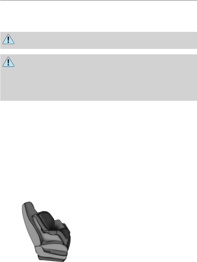
CHILD SEATS
Use a child safety seat (sometimes
called an infant carrier, convertible
seat, or toddler seat) for infants,
toddlers or children weighing
40 pounds (18 kilograms) or less
(generally age four or younger).
CHILD SEAT POSITIONING
WARNING: Airbags can kill or injure a child in a child seat.
Never place a rear-facing child seat in front of an active airbag. If
you must use a forward-facing child seat in the front seat, move the
vehicle seat upon which the child seat is installed all the way back.
When possible, all children age 12 and under should be properly
restrained in a rear seating position. If all children cannot be seated and
restrained properly in a rear seating position, properly restrain the
largest child in the front seat.
WARNING: Always carefully follow the instructions and
warnings provided by the manufacturer of any child restraint to
determine if the restraint device is appropriate for your child’s size,
height, weight, or age. Follow the child restraint manufacturer’s
instructions and warnings provided for installation and use in
conjunction with the instructions and warnings provided by your
vehicle manufacturer. A safety seat that is improperly installed or
utilized, is inappropriate for your child’s height, age, or weight or does
not properly fit the child may increase the risk of serious injury or
death.
WARNING: Never let a passenger hold a child on his or her lap
while your vehicle is moving. The passenger cannot protect the
child from injury in a crash, which may result in serious injury or death.
28 Child Safety
2013 F-650/750 (f67)
Owners Guide gf, 2nd Printing, March 2013
USA (fus)
WARNING: Never use pillows, books, or towels to boost a child.
They can slide around and increase the likelihood of injury or
death in a crash.
WARNING: Always restrain an unoccupied child seat or booster
seat. These objects may become projectiles in a crash or sudden
stop, which may increase the risk of serious injury.
WARNING: Never place, or allow a child to place, the shoulder
belt under a child’s arm or behind the back because it reduces
the protection for the upper part of the body and may increase the risk
of injury or death in a crash.
WARNING: To avoid risk of injury, do not leave children or pets
unattended in your vehicle.
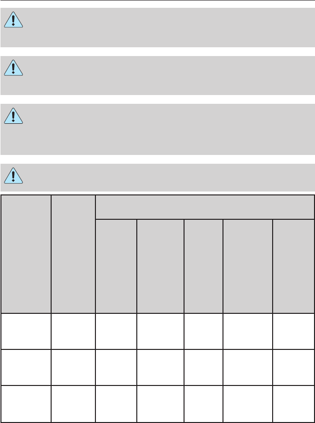
Restraint
Type
Child
Weight
Use any attachment method as indicated
below by “X”
LATCH
(lower
anchors
and
top
tether
anchor)
LATCH
(lower
anchors
only)
Safety
belt
and
top
tether
anchor
Safety
belt and
LATCH
(lower
anchors
and top
tether
anchor)
Safety
belt
only
Rear
facing
child seat
Up to
48 lb
(21 kg)
X
Forward
facing
child seat
Up to
48 lb
(21 kg)
X
Forward
facing
child seat
Over
48 lb
(21 kg)
X
Child Safety 29
2013 F-650/750 (f67)
Owners Guide gf, 2nd Printing, March 2013
USA (fus)
Note: The child seat must rest tightly against the vehicle seat upon
which it is installed. It may be necessary to lift or remove the head
restraint. See the Seats chapter for information on head restraints.
BOOSTER SEATS
WARNING: Never place, or allow a child to place, the shoulder
belt under a child’s arm or behind the back because it reduces
the protection for the upper part of the body and may increase the risk
of injury or death in a crash.
Use a belt-positioning booster seat for children who have outgrown or no
longer properly fit in a child safety seat (generally children who are less
than 4 feet 9 inches (1.45 meters) tall, are greater than age four (4) and
less than age twelve (12), and between 40 pounds (18 kilograms) and
80 pounds (36 kilograms) and upward to 100 pounds (45 kilograms) if
recommended by your child restraint manufacturer). Many state and
provincial laws require that children use approved booster seats until
they reach age eight (8), a height of 4 feet 9 inches (1.45 meters) tall, or
80 pounds (36 kilograms).
Booster seats should be used until you can answer YES to ALL of these
questions when the child is seated without a booster seat.
•Can the child sit all the way
back against their vehicle seat
with knees bent comfortably at
the edge of the seat cushion?
•Can the child sit without
slouching?
•Does the lap belt rest low across the hips?
•Is the shoulder belt centered on the shoulder and chest?
•Can the child stay seated like this for the whole trip?
Always use booster seats in conjunction with your vehicle lap and
shoulder belt.
30 Child Safety
2013 F-650/750 (f67)
Owners Guide gf, 2nd Printing, March 2013
USA (fus)
Types of Booster Seats
•Backless booster seats
If your backless booster seat has a removable shield, remove the shield.
If a vehicle seating position has a low seat back or no head restraint, a
backless booster seat may place your child’s head (as measured at the
tops of the ears) above the top of the seat. In this case, move the
backless booster to another seating position with a higher seat back or
head restraint and lap and shoulder belts, or consider using a high back
booster seat.
•High back booster seats
If, with a backless booster seat, you cannot find a seating position that
adequately supports your child’s head, a high back booster seat would be
a better choice.
Child Safety 31
2013 F-650/750 (f67)
Owners Guide gf, 2nd Printing, March 2013
USA (fus)
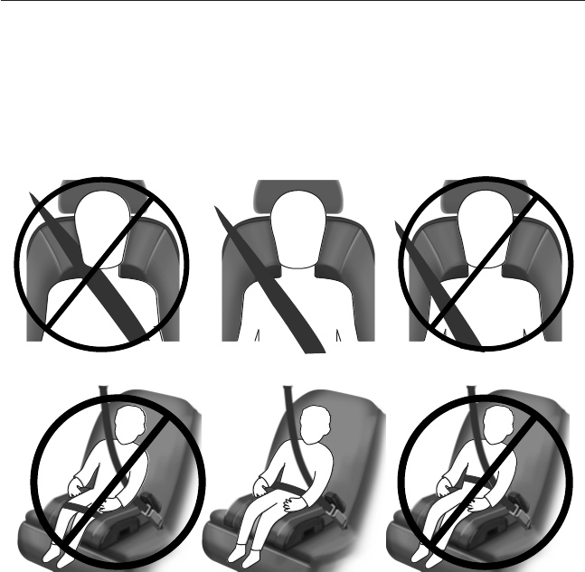
Children and booster seats vary in size and shape. Choose a booster that
keeps the lap belt low and snug across the hips, never up across the
stomach, and lets you adjust the shoulder belt to cross the chest and
rest snugly near the center of the shoulder. The following drawings
compare the ideal fit (center) to a shoulder belt uncomfortably close to
the neck and a shoulder belt that could slip off the shoulder. The
drawings also show how the lap belt should be low and snug across the
child’s hips.
If the booster seat slides on the vehicle seat upon which it is being used,
placing a rubberized mesh sold as shelf or carpet liner under the booster
seat may improve this condition. Do not introduce any item thicker than
this under the booster seat. Check with the booster seat manufacturer’s
instructions.
32 Child Safety
2013 F-650/750 (f67)
Owners Guide gf, 2nd Printing, March 2013
USA (fus)
INSTALLING CHILD SAFETY SEATS
Using Automatic Locking Mode Combination Lap and Shoulder
Belts (Front Passenger and Rear Outboard Seating Positions)
WARNING: Children 12 and under should be properly restrained
in the rear seat whenever possible.
WARNING: Depending on where you secure a child restraint,
and depending on the child restraint design, you may block
access to certain safety belt buckle assemblies and/or LATCH lower
anchors, rendering those features potentially unusable. To avoid risk of
injury, occupants should only use seating positions where they are able
to be properly restrained.
When installing a child safety seat with combination lap/shoulder belts:
•Use the correct safety belt buckle for that seating position.
•Insert the belt tongue into the proper buckle until you hear a snap
and feel it latch. Make sure the tongue is securely fastened in the
buckle.
•Keep the buckle release button pointing up and away from the safety
seat, with the tongue between the child seat and the release button,
to prevent accidental unbuckling.
•Place the vehicle seat back in the upright position.
•This vehicle does not require the use of a locking clip.
Perform the following steps when installing the child seat with
combination lap/shoulder belts:
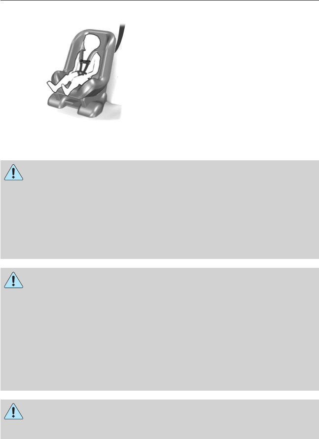
Note: Although the child seat illustrated is a forward-facing child seat,
the steps are the same for installing a rear-facing child seat.
1. Position the child safety seat in a
seat with a combination lap and
shoulder belt.
Child Safety 33
2013 F-650/750 (f67)
Owners Guide gf, 2nd Printing, March 2013
USA (fus)
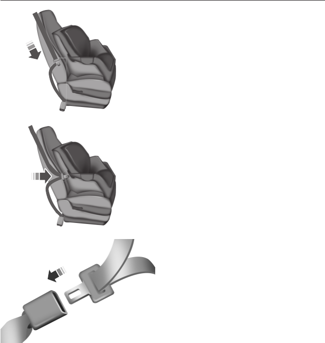
2. Pull down on the shoulder belt
and then grasp the shoulder belt
and lap belt together.
3. While holding the shoulder and
lap belt portions together, route the
tongue through the child seat
according to the child seat
manufacturer’s instructions. Be sure
the belt webbing is not twisted.
4. Insert the belt tongue into the
proper buckle (the buckle closest to
the direction the tongue is coming
from) for that seating position until
you hear a snap and feel the latch
engage. Make sure the tongue is
latched securely by pulling on it.
34 Child Safety
2013 F-650/750 (f67)
Owners Guide gf, 2nd Printing, March 2013
USA (fus)
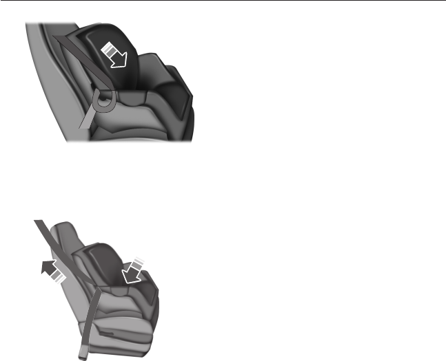
5. To put the retractor in the
automatic locking mode, grasp the
shoulder portion of the belt and pull
downward until all of the belt is
pulled out.
•Allow the belt to retract to
remove slack. The belt will click
as it retracts to indicate it is in
the automatic locking mode.
6. Try to pull the belt out of the retractor to make sure the retractor is
in the automatic locking mode (you should not be able to pull more belt
out). If the retractor is not locked, unbuckle the belt and repeat Step 5.
7. Remove remaining slack from the
belt. Force the seat down with extra
weight (e.g., by pressing down or
kneeling on the child restraint while
pulling up on the shoulder belt in
order to force slack from the belt).
This is necessary to remove the remaining slack that exists once the
additional weight of the child is added to the child restraint. It also helps
to achieve the proper snugness of the child seat to the vehicle.
Sometimes, a slight lean toward the buckle helps to remove remaining
slack from the belt.
8. Attach the tether strap (if the child seat is equipped). See Using
tether straps in this chapter.
Child Safety 35
2013 F-650/750 (f67)
Owners Guide gf, 2nd Printing, March 2013
USA (fus)
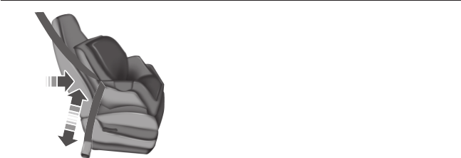
9. Before placing the child in the
seat, forcibly move the seat forward
and back to make sure the seat is
securely held in place.
To check this, grab the seat at the belt path and attempt to move it side
to side and forward and back. There should be no more than one inch
(two and a half centimeters) of movement for proper installation.
Ford recommends checking with a NHTSA Certified Child Passenger
Safety Technician (CPST) to make certain the child restraint is properly
installed. In Canada, check with your local St. John Ambulance office for
referral to a CPST.
Using Lower Anchors and Tethers for CHildren (LATCH)
The LATCH system is composed of three vehicle anchor points: two
lower anchors located where the vehicle seat back and seat cushion meet
(called the seat bight) and one top tether anchor located behind that
seating position. Your vehicle is not equipped with the lower anchor
points in the seat bight. For this vehicle, use the vehicle safety belt and
upper tether to secure a child seat. See Using Tether Straps and
Recommendations for Safety Restraints for Children in this chapter
for more information.
USING TETHER STRAPS
Many forward-facing child safety seats include a tether strap which
extends from the back of the child safety seat and hooks to an anchoring
point called the top tether anchor. Tether straps are available as an
accessory for many older safety seats. Contact the manufacturer of your
child seat for information about ordering a tether strap, or to obtain a
longer tether strap if the tether strap on your safety seat does not reach
the appropriate top tether anchor in the vehicle.
The passenger seats of your vehicle may be equipped with built-in tether
strap anchors located behind the seats as described below.
The tether anchors in your vehicle may be straps on the seat back or an
anchor bracket mounted to the body shell on the back panel.
36 Child Safety
2013 F-650/750 (f67)
Owners Guide gf, 2nd Printing, March 2013
USA (fus)
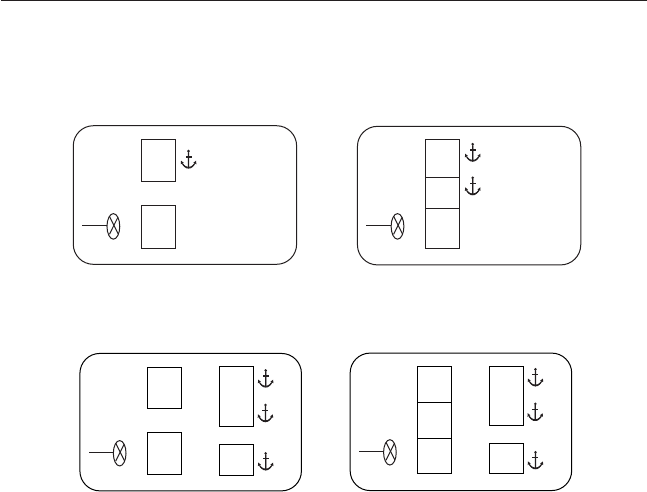
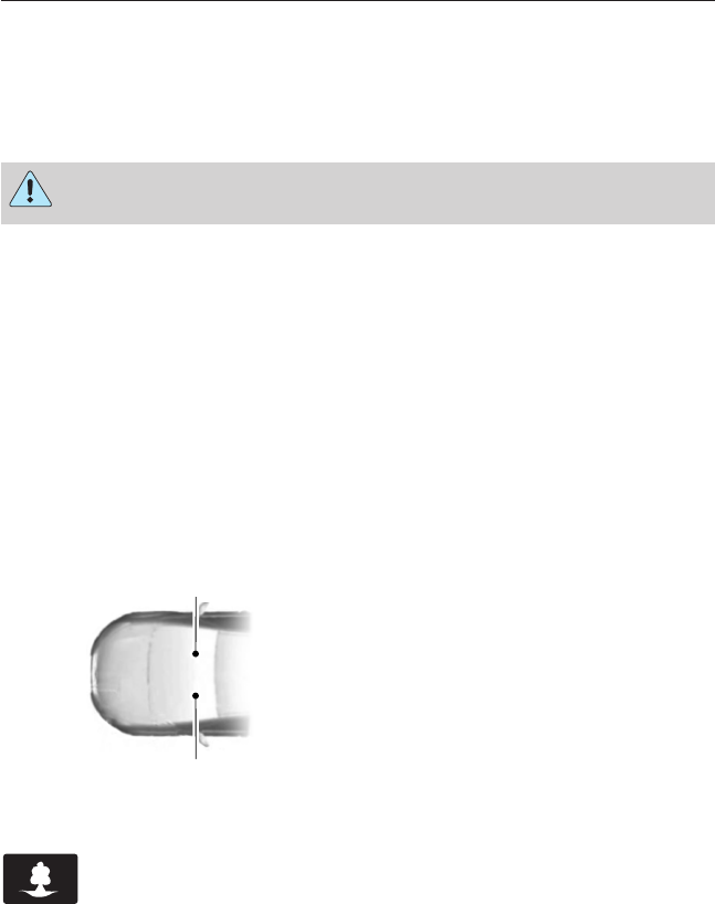
The tether strap anchors in your vehicle are in the following positions
(shown from top view):
•Regular Cab
•Crew Cab
Attach the tether strap only to the appropriate tether anchor as shown.
The tether strap may not work properly if attached somewhere other
than the correct tether anchor.
Once the child safety seat has been installed using the safety belt, you
can attach the top tether strap.
Tether Strap Attachment
1. Route the child safety seat tether strap over the back of the seat.
For vehicles with adjustable head restraints, route the tether strap under
the head restraint and between the head restraint posts, otherwise route
the tether strap over the top of the seat back. If the top of the safety
seat hits the head restraint, raise the head restraint to let the child seat
fit further rearward.
2. Locate the correct anchor for the selected seating position.
Child Safety 37
2013 F-650/750 (f67)
Owners Guide gf, 2nd Printing, March 2013
USA (fus)
3. You may need to pull the seat back forward to access the tether
anchors. Make sure the seat is locked in the upright position before
installing the child seat.
4. Clip the tether strap to the anchor as shown:
•Front seats (Regular Cab) and
Rear seats (Crew Cab)
If the tether strap is clipped incorrectly, the child safety seat may not be
retained properly in the event of a crash.
5. Tighten the child safety seat tether strap according to the
manufacturer’s instructions.
If the safety seat is not anchored properly, the risk of a child being
injured in a crash greatly increases.
If your child restraint system is equipped with a tether strap, and the
child restraint manufacturer recommends its use, Ford also recommends
its use.
Tether Strap Attachment (Rear SuperCab Only)
There are three loops of webbing just above the back of the rear seat
(along the bottom edge of the rear window) in the SuperCab. These
loops are to be used as both routing loops and anchor loops for up to
three child safety seat tether straps.
These straps may be secured below the back of the seat with rubber
bands. To access, reach below the back of the seat and pull the tether
loop out of the rubber band securing it.
38 Child Safety
2013 F-650/750 (f67)
Owners Guide gf, 2nd Printing, March 2013
USA (fus)
Many tether straps cannot be tightened if the tether strap is hooked to
the loop directly behind the child seat. To provide a tight tether strap:
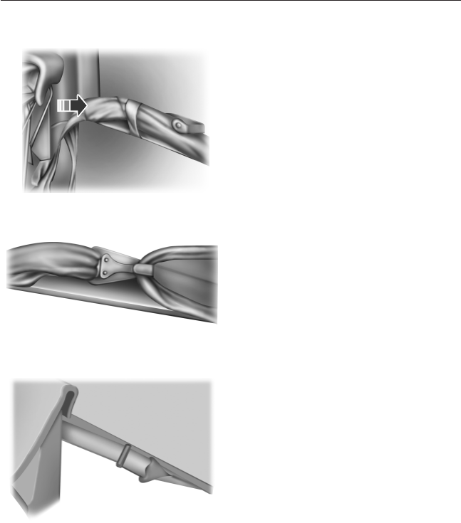
1. Route the tether strap through
the loop directly behind the child
seat.
2. Attach the strap hook onto the
loop behind an adjacent seating
position.
3. Install the child safety seat tightly
using the vehicle belts. Follow the
instructions in this chapter.
4. Tighten the tether strap
according to the child seat
manufacturer’s instructions.
A single loop can be used to route and anchor more than one child seat.
For example, the center loop can be used as a routing loop for a child
safety seat in the center rear seat and as an anchoring loop for child
seats installed in the outboard rear seats.
Child Safety 39
2013 F-650/750 (f67)
Owners Guide gf, 2nd Printing, March 2013
USA (fus)
CHILD SAFETY LOCKS (IF EQUIPPED)
When these locks are set, the rear doors cannot be opened from the
inside.
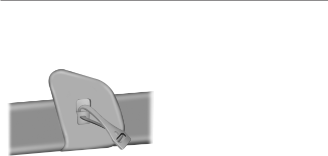
The childproof locks are located on
the rear edge of each rear door and
must be set separately for each
door.
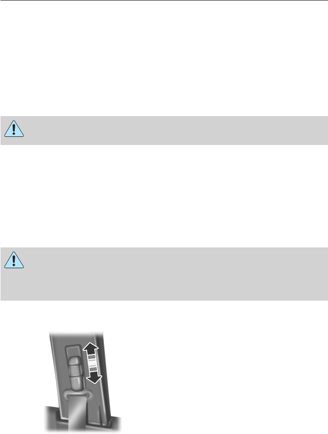
Move the lock control up or down
to engage or disengage the
childproof lock.
40 Child Safety
2013 F-650/750 (f67)
Owners Guide gf, 2nd Printing, March 2013
USA (fus)

PRINCIPLES OF OPERATION
WARNING: Always drive and ride with your seat back upright
and the lap belt snug and low across the hips.
WARNING: To reduce the risk of injury, make sure children sit
where they can be properly restrained.
WARNING: Never let a passenger hold a child on his or her lap
while the vehicle is moving. The passenger cannot protect the
child from injury in a crash.
WARNING: All occupants of the vehicle, including the driver,
should always properly wear their safety belts, even when an
airbag supplemental restraint system (SRS) is provided.
WARNING: It is extremely dangerous to ride in a cargo area,
inside or outside of a vehicle. In a crash, people riding in these
areas are more likely to be seriously injured or killed. Do not allow
people to ride in any area of your vehicle that is not equipped with
seats and safety belts. Be sure everyone in your vehicle is in a seat and
using a safety belt properly.
WARNING: In a rollover crash, an unbelted person is
significantly more likely to die than a person wearing a safety
belt.
WARNING: Each seating position in your vehicle has a specific
safety belt assembly which is made up of one buckle and one
tongue that are designed to be used as a pair. 1) Use the shoulder belt
on the outside shoulder only. Never wear the shoulder belt under the
arm. 2) Never swing the safety belt around your neck over the inside
shoulder. 3) Never use a single belt for more than one person.
WARNING: When possible, all children 12 years old and under
should be properly restrained in a rear seating position.
Safety Belts 41
2013 F-650/750 (f67)
Owners Guide gf, 2nd Printing, March 2013
USA (fus)
WARNING: Safety belts and seats can become hot in a vehicle
that has been closed up in sunny weather; they could burn a
small child. Check seat covers and buckles before you place a child
anywhere near them.
WARNING: Front and rear seat occupants, including pregnant
women, should wear safety belts for optimum protection in an
accident.
The front and rear outboard safety restraints in the vehicle are
combination lap and shoulder belts. The front and rear seat passenger
outboard safety belts have vehicle sensitive emergency locking retractors
and automatic locking retractors.
The safety belt system consists of:
•Lap and shoulder safety belts.
•Shoulder safety belt with automatic locking mode (except driver
safety belt).
•Height adjuster at the front outboard seating positions.
•Safety belt warning light and chime. See Safety belt
warning light and indicator chime later in this chapter.
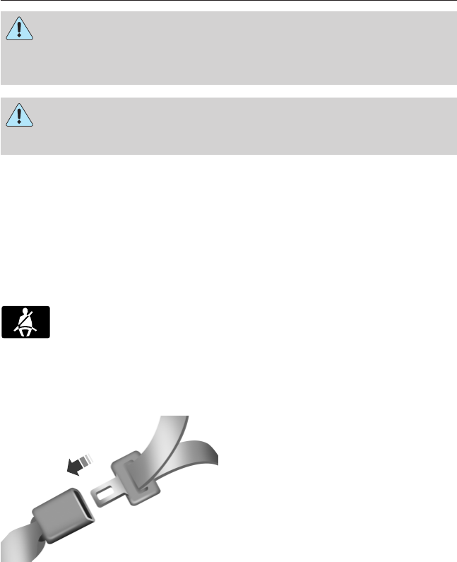
FASTENING THE SAFETY BELTS
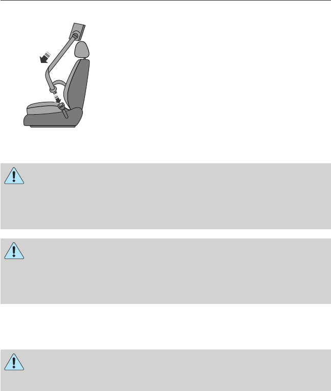
The front and rear outboard safety restraints in the vehicle are
combination lap and shoulder belts.
1. Insert the belt tongue into the
proper buckle (the buckle closest to
the direction the tongue is coming
from) until you hear a snap and feel
it latch. Make sure the tongue is
securely fastened in the buckle.
42 Safety Belts
2013 F-650/750 (f67)
Owners Guide gf, 2nd Printing, March 2013
USA (fus)
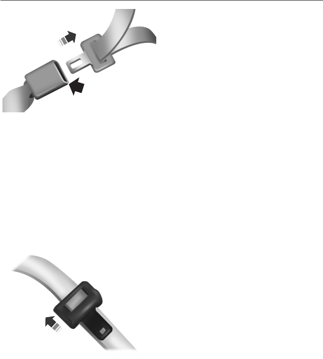
2. To unfasten, press the release
button and remove the tongue from
the buckle.
Using the Safety Belt with Cinch Tongue (Front and Rear Center
Seat)
The cinch tongue slides up and down the belt webbing when the belt is
stowed or while putting safety belts on. When the lap and shoulder
safety belt is buckled, the cinch tongue allows the lap portion to be
shortened, but pinches the webbing to keep the lap portion from getting
longer. The cinch tongue is designed to slip during a crash, so always
wear the shoulder belt properly and do not allow any slack in either the
lap or shoulder portions.
Before you can reach and latch a lap and shoulder belt having a cinch
tongue into the buckle, you may have to lengthen the lap belt portion of it.
1. To lengthen the lap belt, pull
some webbing out of the
shoulder belt retractor.
2. While holding the webbing
below the tongue, grasp the tip
(metal portion) of the tongue so
that it is parallel to the webbing
and slide the tongue upward.
3. Provide enough lap belt length
so that the tongue can reach the
buckle.
Safety Belts 43
2013 F-650/750 (f67)
Owners Guide gf, 2nd Printing, March 2013
USA (fus)
Fastening the Cinch Tongue
WARNING: The lap belt should fit snugly and as low as possible
around the hips, not across the waist.
1. Pull the lap and shoulder belt from the retractor so that the shoulder
belt portion of the safety belt crosses your shoulder and chest.
2. Be sure the belt is not twisted. If the belt is twisted, remove the
twist.
3. Insert the belt tongue into the proper buckle for your seating
position until you hear a snap and feel it latch.
4. Make sure the tongue is securely fastened to the buckle by pulling on
the tongue.
While you are fastened in the safety belt, the lap and shoulder belt with
a cinch tongue adjusts to your movement. However, if you brake hard,
turn hard, or if your vehicle receives an impact of 5 mph (8 km/h) or
more, the safety belt becomes locked and helps reduce your forward
movement.
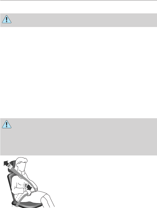
Restraint of Pregnant Women
WARNING: Always ride and drive with your seat back upright
and the safety belt properly fastened. The lap portion of the
safety belt should fit snug and be positioned low across the hips. The
shoulder portion of the safety belt should be positioned across the
chest. Pregnant women should also follow this practice. See the
following figure.
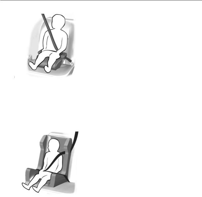
Pregnant women should always
wear their safety belts. The lap belt
portion of a combination lap and
shoulder belt should be positioned
low across the hips below the belly
and worn as tight as comfort will
allow. The shoulder belt should be
positioned to cross the middle of
the shoulder and the center of the
chest.
44 Safety Belts
2013 F-650/750 (f67)
Owners Guide gf, 2nd Printing, March 2013
USA (fus)

Safety Belt Locking Modes
WARNING: After any vehicle crash, all safety belts should be
checked for proper function.
All safety restraints in the vehicle are combination lap and shoulder
belts. The driver safety belt and the optional front and rear center seat
safety belt have the first locking mode described below only. All outboard
passenger and outboard rear safety belts have both types of locking
modes described as follows:
Vehicle Sensitive Mode
This is the normal retractor mode, which allows free shoulder belt length
adjustment to your movements and locking in response to vehicle
movement. For example, if the driver brakes suddenly or turns a corner
sharply, or the vehicle receives an impact of about 5 mph (8 km/h) or
more, the combination safety belts will lock to help reduce forward
movement of the driver and passengers.
In addition, the retractor is designed to lock if the webbing is pulled out
too quickly. If this occurs, let the belt retract slightly and pull webbing
out again in a slow and controlled manner.
Automatic Locking Mode
In this mode, the shoulder belt is automatically pre-locked. The belt will
still retract to remove any slack in the shoulder belt. The automatic
locking mode is not available on the driver safety belt or the optional
front or rear center safety belt.
When to Use the Automatic Locking Mode
This mode should be used any time a child safety seat is installed in a
front outboard passenger seating position or any outboard rear seating
position (if equipped). The optional front and rear seat center safety belt
have a cinch mechanism. Children 12 years old and under should be
properly restrained in a rear seating position whenever possible. See the
Child Safety chapter.
Safety Belts 45
2013 F-650/750 (f67)
Owners Guide gf, 2nd Printing, March 2013
USA (fus)
How to Use the Automatic Locking Mode
1. Buckle the combination lap and shoulder
belt.
2. Grasp the shoulder portion and pull
downward until the entire belt is pulled
out.
•Allow the belt to retract. As the belt
retracts, you will hear a clicking sound.
This indicates the safety belt is now in the
automatic locking mode.
How to Disengage the Automatic Locking Mode
WARNING: After any vehicle crash, the safety belt system at all
passenger seating positions must be checked by an authorized
dealer to verify that the “automatic locking retractor” feature for child
seats is still functioning properly. In addition, all safety belts should be
checked for proper function.
WARNING: Belt and retractor assembly must be replaced if the
safety belt assembly “automatic locking retractor” feature or any
other safety belt function is not operating properly when checked by an
authorized dealer. Failure to replace the belt and retractor assembly
could increase the risk of injury in crashes.
Unbuckle the combination lap and shoulder belt and allow it to retract
completely to disengage the automatic locking mode and activate the
vehicle sensitive (emergency) locking mode.
WARNING: Failure to replace the safety belt assembly under the
above conditions could result in severe personal injuries in the
event of a crash.
46 Safety Belts
2013 F-650/750 (f67)
Owners Guide gf, 2nd Printing, March 2013
USA (fus)
Energy Management Feature
•This vehicle has a safety belt system with an energy management
feature at the front outboard seating positions to help further reduce
the risk of injury in the event of a head-on crash.
•The front outboard safety belt systems have a retractor assembly that
is designed to pay out webbing in a controlled manner. This feature is
designed to help reduce the belt force acting on the occupant’s chest.
Safety Belt Extension Assembly
WARNING: Do not use extensions to change the fit of the
shoulder belt across the torso.
If the safety belt is too short when fully extended, you can obtain a
safety belt extension assembly from an authorized dealer.
Use only extensions manufactured by the same supplier as the safety
belt. Manufacturer identification is located at the end of the webbing on
the label. Also, use the safety belt extension only if the safety belt is too
short for you when fully extended.
SAFETY BELT HEIGHT ADJUSTMENT
WARNING: Position the safety belt height adjusters so that the
belt rests across the middle of your shoulder. Failure to adjust
the safety belt properly could reduce the effectiveness of the safety belt
and increase the risk of injury in a crash.
Adjust the height of the shoulder belt so the belt rests across the middle
of your shoulder.
To adjust the shoulder belt height:
1. Pull on the center button and
slide the height adjuster up or
down.
2. Release the button and pull
down on the height adjuster to
make sure it is locked in place.
PULL
Safety Belts 47
2013 F-650/750 (f67)
Owners Guide gf, 2nd Printing, March 2013
USA (fus)
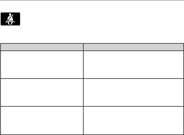
SAFETY BELT WARNING LIGHT AND INDICATOR CHIME
This lamp illuminates and an audible warning sounds if the
driver’s safety belt has not been fastened when the vehicle’s
ignition is turned on.
Conditions of Operation
If... Then...
The driver’s safety belt is not
buckled before the ignition
switch is turned to the on
position...
The safety belt warning light
illuminates 1-2 minutes and the
warning chime sounds 4-8 seconds.
The driver’s safety belt is
buckled while the indicator
light is illuminated and the
warning chime is sounding...
The safety belt warning light and
warning chime turn off.
The driver’s safety belt is
buckled before the ignition
switch is turned to the on
position...
The safety belt warning light and
indicator chime remain off.
48 Safety Belts
2013 F-650/750 (f67)
Owners Guide gf, 2nd Printing, March 2013
USA (fus)

SAFETY BELT-MINDER®
This feature supplements the safety belt warning function by providing
additional reminders by intermittently sounding a chime and illuminating
the safety belt warning light when the driver’s seat is occupied and the
safety belt is unbuckled.
If... Then...
The driver’s safety belt is
buckled before the ignition
switch is turned to the on
position or less than
1-2 minutes have elapsed since
the ignition switch has been
turned to on...
The Belt-Minder® feature does not
activate.
The driver’s safety belt is not
buckled when the vehicle has
reached at least 6 mph
(9.7 km/h) and 1-2 minutes
have elapsed since the ignition
switch has been turned to on...
The Belt-Minder® feature is activated
- the safety belt warning light
illuminates and the warning chime
sounds for six seconds every
25 seconds, repeating for
approximately five minutes or until
the safety belt is buckled.
The driver’s safety belt
becomes unbuckled for
approximately one minute
while the vehicle is traveling at
least 6 mph (9.7 km/h) and
more than 1-2 minutes have
elapsed since the ignition
switch has been turned to on...
The Belt-Minder® feature is activated
- the safety belt warning light
illuminates and the warning chime
sounds for six seconds every
25 seconds, repeating for
approximately five minutes or until
the safety belt is buckled.
Safety Belts 49
2013 F-650/750 (f67)
Owners Guide gf, 2nd Printing, March 2013
USA (fus)

Deactivating and Activating the Belt-Minder® Feature
WARNING: While the design allows you to deactivate your
Belt-Minder®, this system is designed to improve your chances of
being safely belted and surviving an accident. We recommend you leave
the Belt-Minder® system activated for yourself and others who may use
the vehicle. To reduce the risk of injury, do not deactivate or activate
the Belt-Minder® feature while driving the vehicle.
Read Steps 1-4 thoroughly before proceeding with the deactivation or
activation programming procedure.
The system can be deactivated and activated by performing the following
procedure:
Before following the procedure, make sure that:
•the parking brake is set
•the gearshift is in position P(if equipped) or Nfor an automatic
transmission or neutral for a manual transmission
•the ignition is off
•all vehicle doors are closed
•the driver’s safety belt is unbuckled
•the parklamps and headlamps are off.
1. Turn the ignition on. (DO NOT START THE ENGINE.)
2. Wait until the safety belt warning light turns off (approximately one
or two minutes).
•Steps 3–5 must be completed within 60 seconds after the safety
belt warning light turns off, or the procedure has to be repeated.
3. Buckle then unbuckle the safety belt three times at a moderate
speed, ending with the safety belt in the unbuckled state.
4. Turn on the parklamps and headlamps, then turn them off.
5. Buckle then unbuckle the safety belt three times at a moderate
speed, ending with the safety belt in the unbuckled state.
•After Step 5, the safety belt warning light turns on for three
seconds.
6. Within seven seconds of the light turning on, buckle then unbuckle
the safety belt.
•This disables the Belt-Minder® feature if it is currently enabled.
•This enables the Belt-Minder® feature if it is currently disabled.
50 Safety Belts
2013 F-650/750 (f67)
Owners Guide gf, 2nd Printing, March 2013
USA (fus)

Confirmation of disabling Belt-Minder® is provided by the safety belt
warning light flashing four times per second for three seconds.
Confirmation of enabling Belt-Minder® is provided by:
•the safety belt warning light flashing four times per second for three
seconds
•the safety belt warning light turning off
•the safety belt warning light flashing four times per second for three
seconds.
After receiving confirmation, the procedure is complete.
CHILD RESTRAINT AND SAFETY BELT MAINTENANCE
Inspect the vehicle safety belts and child safety seat systems periodically
to make sure they work properly and are not damaged. Inspect the
vehicle and child seat safety belts to make sure there are no nicks, tears
or cuts. Replace if necessary. All vehicle safety belt assemblies, including
retractors, buckles, front safety belt buckle assemblies, buckle support
assemblies (slide bar-if equipped), shoulder belt height adjusters (if
equipped), shoulder belt guide on seat back (if equipped), child safety
seat LATCH and tether anchors, and attaching hardware, should be
inspected after a crash. Read the child restraint manufacturer’s
instructions for additional inspection and maintenance information
specific to the child restraint. Ford Motor Company recommends that all
safety belt assemblies in use in vehicles involved in a crash be replaced.
However, if the crash was minor and an authorized dealer finds that the
belts do not show damage and continue to operate properly, they do not
need to be replaced. Safety belt assemblies not in use during a crash
should also be inspected and replaced if either damage or improper
operation is noted.
For proper care of soiled safety belts, see Cleaning the interior in the
Vehicle Care chapter.
Safety Belts 51
2013 F-650/750 (f67)
Owners Guide gf, 2nd Printing, March 2013
USA (fus)

KEYS
The key operates all locks on your vehicle. In case of loss, replacement
keys are available from your dealer.
You should always carry a second key with you in a safe place in case
you require it in an emergency.
52 Keys and Remote Control
2013 F-650/750 (f67)
Owners Guide gf, 2nd Printing, March 2013
USA (fus)
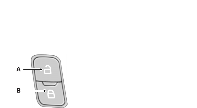
LOCKING AND UNLOCKING
You can use the power door lock control to lock and unlock the vehicle.
Power Door Locks (If Equipped)
The power door lock control is located on the driver and front passenger
door panels.
A. Unlock
B. Lock
Locks 53
2013 F-650/750 (f67)
Owners Guide gf, 2nd Printing, March 2013
USA (fus)
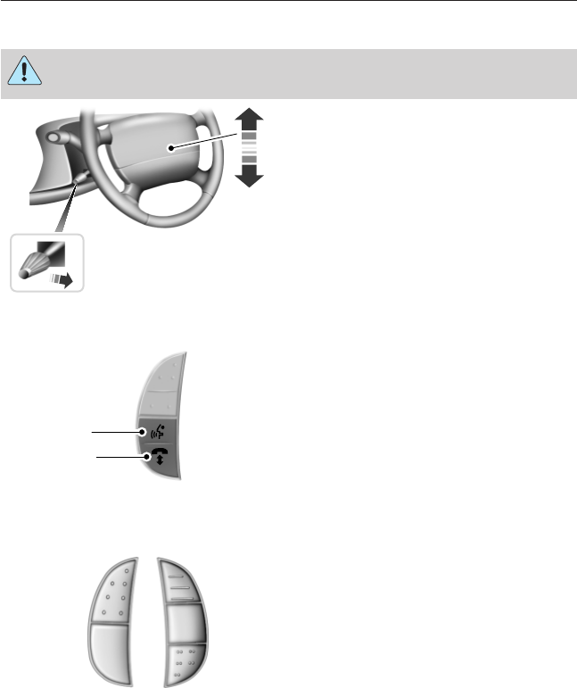
ADJUSTING THE STEERING WHEEL
WARNING: Do not adjust the steering wheel when your vehicle
is moving.
1. Pull and hold the steering wheel
release lever.
2. Adjust the steering wheel to the
desired position then release the
lever.
VOICE CONTROL (IF EQUIPPED)
A. Voice recognition
B. Phone mode
See the SYNC chapter.
CRUISE CONTROL (IF EQUIPPED)
See the Cruise Control chapter.
1
2
A
B
ON
OFF
RES
SET
ACCEL
COAST
ON
OFF
54 Steering Wheel
2013 F-650/750 (f67)
Owners Guide gf, 2nd Printing, March 2013
USA (fus)
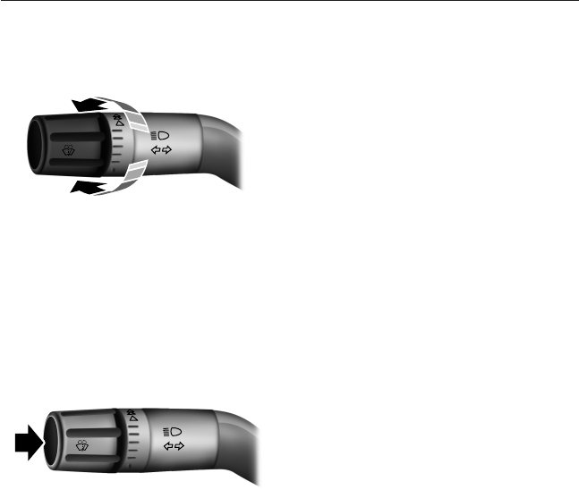
WINDSHIELD WIPERS
Note: Fully defrost the windshield in icy conditions before turning on
the windshield wipers.
Rotate the end of the control away
from you to increase the speed of
the wipers. Rotate toward you to
decrease the speed of the wipers.
WINDSHIELD WASHERS
Note: Do not operate the wipers on a dry windshield. This may scratch
the glass, damage the wiper blades or cause the wiper motor to burn out.
Always use the windshield washer before wiping a dry windshield.
Note: Do not operate the washers when the washer reservoir is empty.
This may cause the washer pump to overheat.
Press the end of the stalk to
activate the washer.
•A brief press causes a single wipe without washer fluid.
•A quick press and hold causes the wipers to swipe three times with
washer fluid.
•A long press and hold will activate the wipers and washer fluid for up
to 10 seconds.
Wipers and Washers 55
2013 F-650/750 (f67)
Owners Guide gf, 2nd Printing, March 2013
USA (fus)
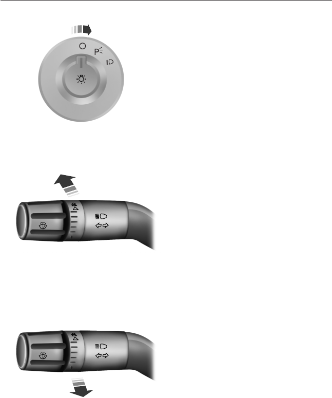
LIGHTING CONTROL
•Rotate the headlamp control
clockwise to the first position to
turn on the parking lamps.
•Rotate clockwise to the second
position to also turn on the
headlamps.
High Beams
•Push the lever toward the
instrument panel to activate.
•Pull the lever toward you to
deactivate.
Headlamp Flasher
Pull toward you slightly to activate
and release to deactivate.
56 Lighting
2013 F-650/750 (f67)
Owners Guide gf, 2nd Printing, March 2013
USA (fus)
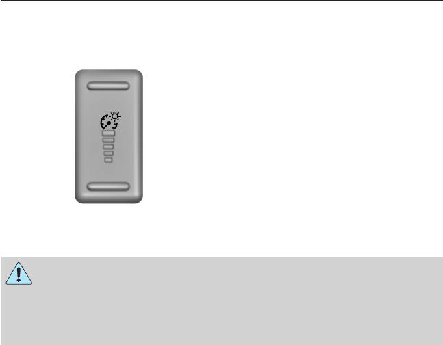
INSTRUMENT LIGHTING DIMMER
Use to adjust the brightness of the instrument panel and all applicable lit
components in the vehicle during headlamp and parking lamp operation.
•Tapthetoporbottomofthe
control to brighten or dim all
interior lit components
incrementally, or
•press and hold at the first
position the top or bottom of the
control until the desired lighting
level is reached.
DAYTIME RUNNING LAMPS (DRL) (IF EQUIPPED)
WARNING: Always remember to switch your headlamps on in
low light situations or during inclement weather. The system does
not activate the tail lamps and may not provide adequate lighting
during these conditions. Failure to activate your headlamps under these
conditions may result in a crash.
The system switches the headlamps on with a reduced output in daylight
conditions.
To switch the system on:
1. Switch the ignition on.
2. Switch the lighting control to the off or parking lamp position.
Lighting 57
2013 F-650/750 (f67)
Owners Guide gf, 2nd Printing, March 2013
USA (fus)

DIRECTION INDICATORS
•Push down to activate the left
turn signal.
•Push up to activate the right turn
signal.
If your vehicle is a tractor, the turn signals may not shut off when a turn
is completed. This is normal. See your dealer if there are any questions
about your vehicle’s options.
INTERIOR LAMPS
The map lamps are located on the overhead console.
Press the controls on either side of
each map lamp to turn on the
lamps.
The map lamps also light when:
•Any door is opened.
•Any of the remote entry controls
are pressed and the ignition is off.
58 Lighting
2013 F-650/750 (f67)
Owners Guide gf, 2nd Printing, March 2013
USA (fus)
POWER WINDOWS (IF EQUIPPED)
WARNING: Do not leave children unattended in your vehicle
and do not let them play with the power windows. They may
seriously injure themselves.
WARNING: When closing the power windows, you should verify
they are free of obstructions and make sure that children and
pets are not in the proximity of the window openings.
Note: You may hear a rumbling noise when one or both of the rear
windows are open. Lower a front window slightly to reduce this noise.
Press the switch to open the
window.
Lift the switch to close the window.
One-Touch Up or Down (Front Windows)
Note: The window may be disabled for up to five minutes if it is cycled
up and down repeatedly. This helps prevent damage to the motor.
Normal operation will resume once the motor cools.
This feature automatically opens or closes the window.
Press or lift the switch completely and release. The window will fully
open or close. Press or lift it again to stop the window.
Restoring the One-Touch Up Functionality
Note: Perform one-touch up re-calibration with the door closed.
Calibrating with the door open will cause the window to continuously
bounce back.
Functionality may be lost under low battery power conditions.
To reset this function after restoring full battery power:
1. Pull the switch to the one-touch up position.
2. Hold the switch until the glass reaches the stall position and continue
to hold for two seconds.
3. Press the switch down and operate the window to the full down
position. One-touch up will now be functional.
AUTO
Windows and Mirrors 59
2013 F-650/750 (f67)
Owners Guide gf, 2nd Printing, March 2013
USA (fus)
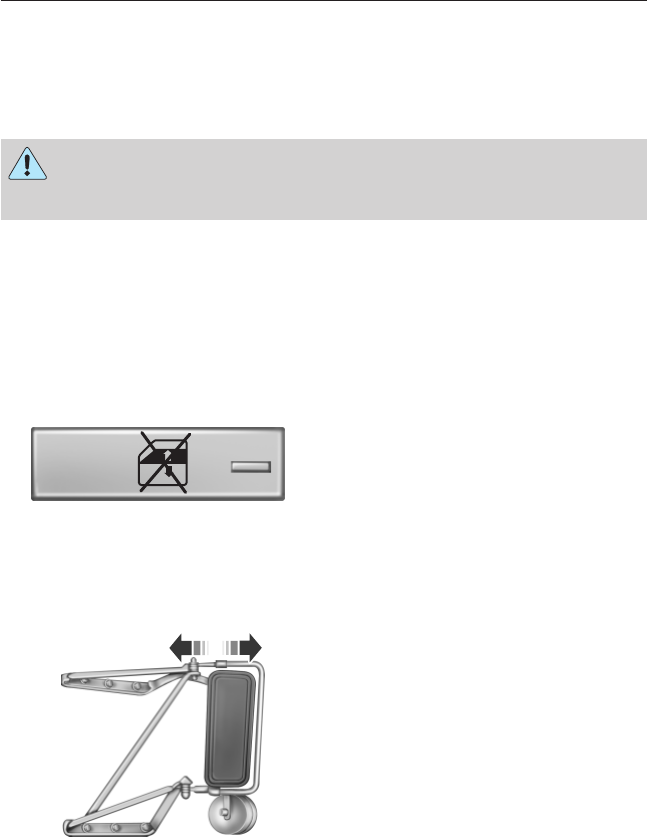
Bounce-Back (One-Touch Up or Down Windows Only)
The window will stop automatically while closing and reverse some
distance if there is an obstacle in the way.
Overriding the Bounce-Back Feature
WARNING: When you override the bounce-back feature the
window will not reverse if it detects an obstacle. Take care when
closing the windows to avoid personal injury or damage to your vehicle.
Pull up the window switch and hold within two seconds of the window
reaching the bounce-back position. The window will travel up with no
bounce-back protection. The window will stop if you release the switch
before the window is fully closed.
Window Lock
This feature allows only the driver
and front passenger to operate the
power windows.
To lock the window controls, press
the switch. A light on the switch
illuminates when the windows are
locked. Press the switch again to
restore the window controls.
EXTERIOR MIRRORS
With the doors closed and the seat
adjusted for proper comfort, move
the mirrors to maximize rear
viewing area by adjusting the
mirrors left or right as required.
60 Windows and Mirrors
2013 F-650/750 (f67)
Owners Guide gf, 2nd Printing, March 2013
USA (fus)
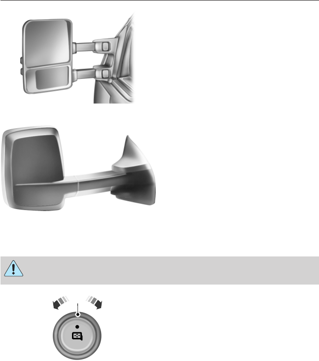
Adjust the auxiliary convex mirrors.
Convex mirrors are a ball-stud
design for precise adjustment to
maximize viewing area.
Power Exterior Mirrors (If Equipped)
WARNING: Do not adjust the mirror while the vehicle is in
motion.
A. Left-hand mirror
B. Off
C. Right-hand mirror
To adjust your mirrors:
1. Select the mirror you want to adjust.
2. Move the control in the direction you want to tilt the mirror.
3. Return the control to the center position to lock mirrors in place.
The spotter mirror (if equipped) must be adjusted manually.
B
AC
Windows and Mirrors 61
2013 F-650/750 (f67)
Owners Guide gf, 2nd Printing, March 2013
USA (fus)
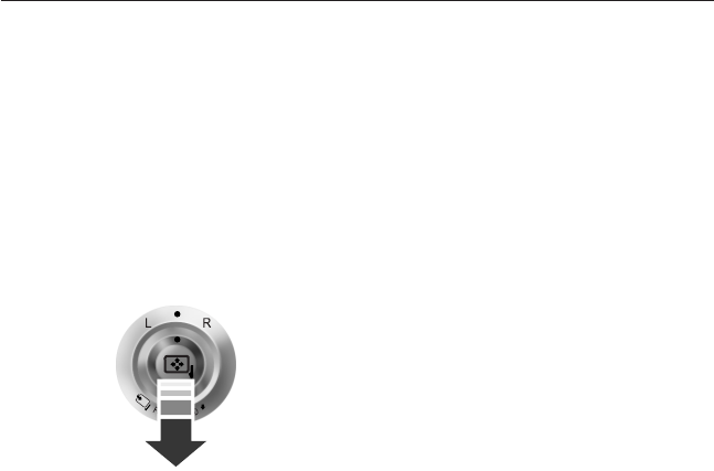
Fold-Away Exterior Mirrors
Push the mirror toward the door window glass. Make sure that you fully
engage the mirror in its support when returning it to its original position.
Power-Folding Mirrors (If Equipped)
Note: Activating the mirrors 10 or more times within one minute, or
repeated folding and unfolding of the mirrors while holding the control
down during full travel, may disable the system to protect motors from
overheating. Wait approximately three minutes with the vehicle running,
and up to 10 minutes with the vehicle off, for the system to reset and for
function to return to normal.
Pull the control back to fold the
mirrors in or out.
Loose Mirror
A power-folding mirror may also be manually folded by pulling it toward
the door window glass. This may cause the mirror to appear loose and it
will need to be re-synchronized. Pull and hold the control to fold the
mirrors in until movement stops. A click will be heard indicating
re-synchronization. If the click is not heard, use the control to fold the
mirrors all the way out, then in again. Once the click is heard the mirrors
will operate normally until they are again manually folded.
Heated Exterior Mirror (If Equipped)
The heated exterior mirrors switch on with the heated mirror switch. See
Heated mirrors in the Climate Control chapter.
Signal Indicator Mirrors (If Equipped)
The outer portion of the appropriate mirror housing blinks when you
activate the turn signal.
Clearance Lamps (If Equipped)
The lower, outer portion of the mirror housings illuminates when the
headlamps or parking lamps are switched on.
62 Windows and Mirrors
2013 F-650/750 (f67)
Owners Guide gf, 2nd Printing, March 2013
USA (fus)
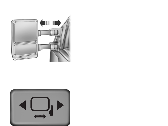
Telescoping Mirrors (If Equipped)
This feature allows the mirror to
extend approximately 3 inches
(75 millimeters). It is especially
useful when towing a trailer. The
mirrors can be manually pulled out
or pushed in to the desired position.
PowerScope® Power Telescoping Mirrors (If Equipped)
This feature lets you position both
mirrors at the same time. The
switch is on the door trim panel.
To telescope the mirrors out, press and hold the left side of the switch.
When the mirrors are fully extended, it is normal to hear the telescoping
motors running as long as you continue to hold the switch.
To telescope the mirrors in, press and hold the right side of the switch.
Windows and Mirrors 63
2013 F-650/750 (f67)
Owners Guide gf, 2nd Printing, March 2013
USA (fus)
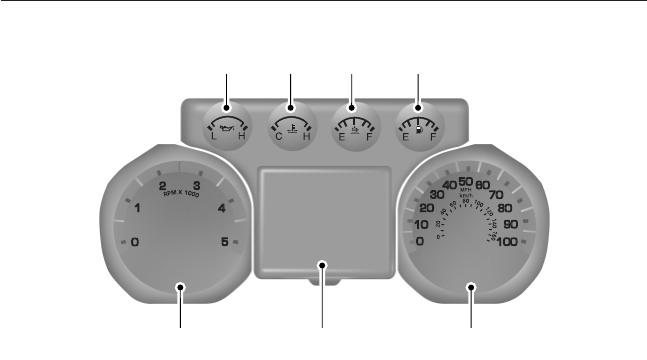
GAUGES - DIESEL ENGINE
Cluster shown in standard measure. Metric similar.
A. Engine oil pressure gauge
B. Engine coolant temperature gauge
C. Diesel exhaust fluid (DEF) gauge
D. Fuel gauge
E. Speedometer
F. Information display. See the Information Displays chapter for more
information.
G. Tachometer
Engine Oil Pressure Gauge
Indicates engine oil pressure. The needle should stay in the normal
operating range. If the needle falls below the normal range, stop the
vehicle, turn off the engine and check the engine oil level. Add oil if
needed. If the oil level is correct, have your vehicle checked at your
authorized dealer.
A
G F E
B C D
64 Instrument Cluster
2013 F-650/750 (f67)
Owners Guide gf, 2nd Printing, March 2013
USA (fus)

Engine Coolant Temperature Gauge
Indicates engine coolant temperature. At normal operating temperature,
the level indicator is in the normal range. If the engine coolant
temperature exceeds the normal range, stop the vehicle as soon as safely
possible, switch off the engine and let the engine cool.
WARNING: Never remove the coolant reservoir cap while the
engine is running or hot.
Diesel Exhaust Fluid (DEF) Gauge
Indicates fluid level in DEF tank.
Fuel Gauge
Indicates approximately how much fuel is left in the fuel tank (when the
ignition is on). The fuel gauge may vary slightly when the vehicle is in
motion or on a grade. The fuel icon and arrow indicates which side of
the vehicle the fuel filler door is located.
Information Display
Odometer: Located in the bottom of the information display. Registers
the accumulated distance your vehicle has travelled.
Trip Computer: See General information in the Information Displays
chapter.
Vehicle Settings and Personalization: See General information in
the Information Displays chapter.
Instrument Cluster 65
2013 F-650/750 (f67)
Owners Guide gf, 2nd Printing, March 2013
USA (fus)
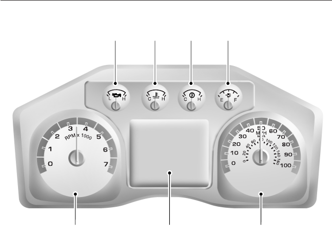
GAUGES - GASOLINE ENGINE
Cluster shown in standard measure. Metric similar.
A. Engine oil pressure gauge
B. Engine coolant temperature gauge
C. Transmission fluid temperature gauge
D. Fuel gauge
E. Speedometer
F. Information display. See the Information Displays chapter for more
information.
G. Tachometer
Engine Oil Pressure Gauge
Indicates engine oil pressure. The needle should stay in the normal
operating range. If the needle falls below the normal range, stop the
vehicle, turn off the engine and check the engine oil level. Add oil if
needed. If the oil level is correct, have your vehicle checked at your
authorized dealer.
A B C D
G F E
66 Instrument Cluster
2013 F-650/750 (f67)
Owners Guide gf, 2nd Printing, March 2013
USA (fus)

Engine Coolant Temperature Gauge
Indicates engine coolant temperature. At normal operating temperature,
the level indicator is in the normal range. If the engine coolant
temperature exceeds the normal range, stop the vehicle as soon as safely
possible, switch off the engine and let the engine cool.
WARNING: Never remove the coolant reservoir cap while the
engine is running or hot.
Transmission Fluid Temperature Gauge
Indicates transmission fluid temperature. At normal operating
temperature, the level indicator is in the normal range. If the
transmission fluid temperature exceeds the normal range, stop the
vehicle as soon as safely possible and verify the airflow is not restricted,
such as snow or debris blocking airflow through the grill. Also, higher
than normal operating temperature can be caused by special operation
conditions (i.e., snowplowing, towing or off-road use). Operating the
transmission for extended periods of time with the gauge in the higher
than normal area may cause internal transmission damage. Altering the
severity of the driving conditions is recommended to lower the
transmission temperature into the normal range. If the gauge continues
to show high temperatures, see your authorized dealer.
Fuel Gauge
Indicates approximately how much fuel is left in the fuel tank (when the
ignition is on). The fuel gauge may vary slightly when the vehicle is in
motion or on a grade. The fuel icon and arrow indicates which side of
the vehicle the fuel filler door is located.
Information Display
Odometer: Located in the bottom of the information display. Registers
the accumulated distance your vehicle has travelled.
Trip Computer: See General information in the Information Displays
chapter.
Vehicle Settings and Personalization: See General information in
the Information Displays chapter.
Instrument Cluster 67
2013 F-650/750 (f67)
Owners Guide gf, 2nd Printing, March 2013
USA (fus)
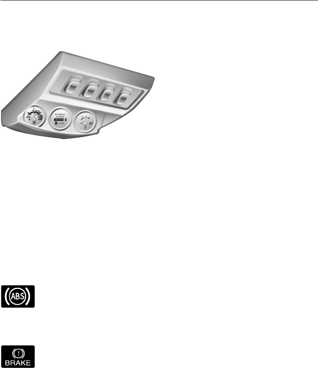
Gauge Package (If Equipped)
Your vehicle may be equipped with an optional gauge package which has
one of the following configurations:
1. Transmission temperature
gauge: Displays the
transmission temperature at the
transmission sump.
2. Hourmeter: Displays the hours
of engine run time.
3. Voltmeter: Displays electrical
system voltage.
WARNING LAMPS AND INDICATORS
The following warning lamps and indicators alert you to a vehicle
condition that may become serious. Some lamps illuminate when you
start your vehicle to make sure they work. If any lamps remain on after
starting your vehicle, see the respective system warning lamp for further
information.
Note: Some warning indicators appear in the information display and
function the same as a warning lamp but do not display when you start
your vehicle.
Anti-Lock Braking System
If it illuminates when you are driving, this indicates a
malfunction. You continue to have the normal braking system
(without ABS) unless the brake warning lamp is also
illuminated. Have the system checked by your authorized dealer.
Brake System
To confirm the brake system warning light is functional, it
momentarily illuminates when the ignition is turned to the on
position when the engine is not running, or in a position
between on and start.
If the brake system warning light does not illuminate at this time, seek
service immediately from your authorized dealer.
68 Instrument Cluster
2013 F-650/750 (f67)
Owners Guide gf, 2nd Printing, March 2013
USA (fus)
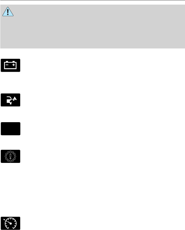
WARNING: Driving a vehicle with the brake system warning
light on is dangerous. A significant decrease in braking
performance may occur. It takes you longer to stop the vehicle. Have
the vehicle checked by your authorized dealer. Driving extended
distances with the parking brake engaged can cause brake failure and
the risk of personal injury.
Charging System
It illuminates when the 12–volt battery is not charging properly.
Contact your authorized dealer as soon as possible. This
indicates a problem with the electrical system or a related
component.
Check Fuel Cap (gasoline engine only)
It illuminates when the fuel cap may not be properly installed.
Continued driving with this light on may cause the service
engine soon warning indicator to come on.
Check Suspension
It illuminates when the air suspension dump switch has been
activated.
Check Transmission (Allison automatic transmission only)
It illuminates while driving if a problem has been detected in
the transmission; shifting may be restricted. Depending on the
severity of the problem, the shifter’s digital read-out may turn
blank.
On MD 3000 series transmissions, operation may continue in order to
reach service assistance. The control unit may not respond to shift
selector requests, since operating limitations are being placed on the
transmission (i.e. upshifts and downshifts may be restricted). Direction
changes do not occur.
Cruise Control
It illuminates when you switch this feature on.
CK
SUSP
Instrument Cluster 69
2013 F-650/750 (f67)
Owners Guide gf, 2nd Printing, March 2013
USA (fus)
Diesel Exhaust Fluid (diesel engine only)
It illuminates when the diesel exhaust fluid level falls below
0.5 gallons (1.9L) in the five gallon (19.0L) tank or one gallon
(3.8L) in the nine gallon (34.0L) tank. Refill the tank or, at a
minimum, add at least one gallon (3.8L) to the five gallon (19.0L) tank
or two gallons (7.6L) to the nine gallon (34.0L) tank.
Diesel Particulate Filter (diesel engine only)
It illuminates when the soot level in the diesel particulate filter
has reached a point where it requires operator assistance. See
Diesel particulate filter in the Maintenance chapter, and your
engine operator’s manual, for more details.
Do Not Shift (Allison automatic transmission only)
It illuminates while driving if a problem has been detected in
the transmission; shifting may be restricted. Depending on the
severity of the problem, the shifter’s digital read-out may turn
blank.
Operation may continue in order to reach service assistance. The control
unit may not respond to shift selector requests, since operating
limitations are being placed on the transmission (i.e. upshifts and
downshifts may be restricted). Direction changes do not occur.
Direction Indicator
It illuminates when the left or right turn signal or the hazard
warning flasher is switched on. If the indicators stay on or flash
faster, check for a burned out bulb.
Electronic Locking Differential
It illuminates when using the electronic locking differential.
Engine Oil Pressure (gasoline engine only)
It illuminates when engine oil pressure is low.
Fasten Safety belt
It illuminates and a chime sounds to remind you to fasten your
safety belt.
70 Instrument Cluster
2013 F-650/750 (f67)
Owners Guide gf, 2nd Printing, March 2013
USA (fus)
High Beam
It illuminates when the headlamp high beam is switched on.
Low Fuel Level (gasoline engine only)
It illuminates when the fuel level is low or near empty. Refuel
as soon as possible.
Parking Brake Warning
It momentarily illuminates when the ignition is switched to the
on position (with the engine off). It also illuminates when the
parking brake is engaged. If the parking brake warning lamp
does not illuminate at these times, seek service immediately.
Vehicles equipped with the Power Park Parking Brake option: If
the park brake warning lamp begins to blink after setting the parking
brake on your vehicle, this may indicate a failure in the parking brake
system. Seek service from your dealer immediately.
Powertrain Malfunction/Reduced Power/Electronic Throttle
Control (gasoline engine only)
It illuminates when a powertrain fault has been detected.
Contact your authorized dealer as soon as possible.
Service Engine Soon
It illuminates when the ignition is first switched to the on
position to check the bulb and to indicate whether the vehicle
is ready for Inspection/Maintenance (I/M) testing.
Solid illumination after the engine is started indicates the on-board
diagnostics system (OBD-II) has detected a malfunction.
WARNING: Under engine misfire conditions, excessive exhaust
temperatures could damage the catalytic converter, the fuel
system, interior floor coverings or other vehicle components, possibly
causing a fire.
P
Instrument Cluster 71
2013 F-650/750 (f67)
Owners Guide gf, 2nd Printing, March 2013
USA (fus)
Stop Engine (diesel engine only)
This red lamp illuminates when the engine needs to be stopped
(as soon as it can be safely done). If the lamp begins flashing,
automatic engine shutdown may take place in as little as
20 seconds.
WARNING: In the event of engine shutdown, make sure the
vehicle is safely off the road and the problem is remedied prior to
returning to the road. Failure to remove the vehicle from the road
could result in an accident, causing serious injury or death.
If the engine shuts down, it can be restarted and operated for
30 seconds at a time, or until the problem is corrected. For more
information, see Engine automatic shutdown warning light or chime
in the Driving chapter, and your engine operator’s manual.
See your engine operator’s manual for specific information regarding this
feature. Drivers of electronically-controlled engines should know the
extent of the warning engine shutdown system before operating the
vehicle.
Traction Control (diesel engine only)
It illuminates and flashes slowly if the Off Road or Mud/Snow
mode is selected. It illuminates and flashes rapidly during a
traction control event.
Trailer Anti-Lock Braking System (ABS)
It illuminates briefly when the ignition is switched on and only
when a PLC trailer or a PLC diagnostic tool is connected. If the
light fails to illuminate, remains on after the vehicle is started
or continues to flash, have the system serviced immediately.
Wait to Start (diesel engine only)
It illuminates when the air intake heater is in operation and
special starting procedures are required.
WARNING: If equipped with an air intake heater, DO NOT use
ether or any other starting fluids. The use of starting fluids
(ether) in an engine equipped with an air intake heater could result in
damage and/or personal injury.
72 Instrument Cluster
2013 F-650/750 (f67)
Owners Guide gf, 2nd Printing, March 2013
USA (fus)
Water in Fuel (diesel engine only)
It illuminates when the fuel filter/water separator has a
significant quantity of water in it.
If the light illuminates when the engine is running, stop the vehicle as
soon as safely possible, shut off the engine, then drain the fuel
filter/water separator. See your engine operator’s manual for the drain
procedure. Allowing water to stay in the system could result in extensive
damage to, or failure of, the fuel injection system.
WARNING: Do not drain the water separator while the engine is
running. Fuel may ignite if the separator is drained while the
engine is running or the vehicle is moving.
AUDIBLE WARNINGS AND INDICATORS
Key In Ignition Warning Chime
Sounds when the key is left in the ignition in the off or accessory
position and the driver’s door is opened.
Sounds when the keyless vehicle is in RUN and the driver’s door is
opened (if equipped).
Headlamps On Warning Chime
Sounds when the headlamps or parking lamps are on, the ignition is off
(the key is not in the ignition) and the driver’s door is opened.
Instrument Cluster 73
2013 F-650/750 (f67)
Owners Guide gf, 2nd Printing, March 2013
USA (fus)
GENERAL INFORMATION
WARNING: Driving while distracted can result in loss of vehicle
control, accident and injury. Ford strongly recommends that
drivers use extreme caution when using any device or feature that may
take their focus off the road. Your primary responsibility is the safe
operation of the vehicle. We recommend against the use of any
handheld device while driving and that you comply with all applicable
laws.
Various systems on your vehicle can be controlled using the information
display controls on the steering wheel. Corresponding information is
displayed in the information display.
Information Display Controls
•Press the INFO button to scroll
through trip and fuel usage
information.
•Press the SETUP button to
scroll through various vehicle
feature settings.
•Press the RESET button to
choose settings, reset
information and confirm
messages.
Info
Press the INFO button repeatedly to cycle through the following
features:
Note: Some options may appear slightly different or not at all if the
items are optional.
INFO
TRIP A/B
MILES (km) TO E
AVG MPG (L/100 km)
TIMER
BLANK SCREEN
INFO SETUP RESET
74 Information Displays
2013 F-650/750 (f67)
Owners Guide gf, 2nd Printing, March 2013
USA (fus)
•TRIP A/B: Registers the distance of individual journeys. Press and
release the INFO button until the A or B trip appears in the display
(this represents the trip mode). Press the RESET button to reset.
See System check and vehicle feature customization later in this
section to switch the display from metric to English.
•MILES (KILOMETERS) TO E: This displays an estimate of
approximately how far you can drive with the fuel remaining in your
tank under normal driving conditions. Remember to turn the ignition
off when refueling to allow this feature to correctly detect the added
fuel. Distance to empty is calculated using a running average fuel
economy, which is based on your recent driving history of 500 miles
(800 kilometers). This value is not the same as the average fuel
economy display. The running average fuel economy is re-initialized
to a factory default value if the battery is disconnected.
•AVG MPG (L/100 km): Average fuel economy displays your average
fuel economy in miles/gallon or liters/100 km.
•TIMER: Displays the trip elapsed drive time. Press and release
RESET to pause the timer. Press and hold RESET to reset the timer.
System Check and Vehicle Feature Customization
Press the SETUP button repeatedly
to cycle the message center through
the following features:
SETUP
RESET FOR
SYSTEM CHECK
Press the
RESET button.
OIL LIFE
CHARGING SYSTEM
BRAKE SYSTEM
MILES TO EMPTY
UNITS Press the
RESET button.
English or Metric
LANGUAGE =
ENGLISH /
SPANISH / FRENCH
Press the
RESET button.
English / Spanish / French
(Press and hold to set.)
INFO SETUP RESET
Information Displays 75
2013 F-650/750 (f67)
Owners Guide gf, 2nd Printing, March 2013
USA (fus)

INFORMATION MESSAGES
Note: Depending on the vehicle options equipped with your vehicle, not
all of the messages display or are available. Certain messages may be
abbreviated or shortened depending upon which cluster type you have.
Press the OK button to acknowledge and remove some messages from
the information display. Other messages are removed automatically after
a short time. Certain messages need to be confirmed before you can
access the menus.
Battery and
Charging System
Messages
Action / Description
CHECK CHARGING
SYSTEM
Displayed when the charging system needs
servicing. If the warning stays on or continues
to come on, contact your authorized dealer as
soon as possible.
Brake System
Messages
Action / Description
BRAKE FLUID
LEVEL LOW
Displayed when the brake fluid level is low
and the brake system should be inspected
immediately. See Brake fluid check in the
Maintenance chapter.
CHECK BRAKE
SYSTEM
Displayed when the brake system needs
servicing. If the warning stays on or continues
to come on, contact your authorized dealer as
soon as possible.
PARK BRAKE
ENGAGED
Displayed when the parking brake is set and
the vehicle is in motion.
76 Information Displays
2013 F-650/750 (f67)
Owners Guide gf, 2nd Printing, March 2013
USA (fus)

GENERAL INFORMATION
Radio Frequencies and Reception Factors
AM and FM frequencies are established by the Federal Communications
Commission (FCC) and the Canadian Radio and Telecommunications
Commission (CRTC). Those frequencies are:
AM: 530, 540–1700, 1710 kHz
FM: 87.9–107.7, 107.9 MHz
Radio reception factors
Distance and
strength
The further you travel from an FM station,
the weaker the signal and the weaker the
reception.
Terrain Hills, mountains, tall buildings, bridges,
tunnels, freeway overpasses, parking garages,
dense tree foliage and thunderstorms can
interfere with the reception.
Station overload When you pass a ground-based broadcast
repeating tower, a stronger signal may
overtake a weaker one and result in the audio
system muting.
CD and CD Player Information
Note: CD units play commercially pressed 4.75-inch (12 centimeter)
audio compact discs only. Due to technical incompatibility, certain
recordable and re-recordable compact discs may not function correctly
when used in Ford CD players.
Note: Do not insert CDs with homemade paper (adhesive) labels into
the CD player as the label may peel and cause the CD to become
jammed. You should use a permanent felt tip marker rather than
adhesive labels on your homemade CDs. Ballpoint pens may damage
CDs. Please contact your authorized dealer for further information.
Note: Do not use any irregularly shaped discs or discs with a scratch
protection film attached.
Always handle discs by their edges only. Clean the disc with an approved
CD cleaner only. Wipe it from the center of the disc toward the edge. Do
not clean in a circular motion.
Do not expose discs to direct sunlight or heat sources for extended
periods.
Audio System 77
2013 F-650/750 (f67)
Owners Guide gf, 2nd Printing, March 2013
USA (fus)

MP3 Track and Folder Structure
Audio systems capable of recognizing and playing MP3 individual tracks
and folder structures work as follows:
•There are two different modes for MP3 disc playback: MP3 track
mode (system default) and MP3 folder mode.
•MP3 track mode ignores any folder structure on the MP3 disc. The
player numbers each MP3 track on the disc (noted by the .mp3 file
extension) from T001 to a maximum of T255. Note: The maximum
number of playable MP3 files may be less depending on the structure
of the CD and exact model of radio present.
•MP3 folder mode represents a folder structure consisting of one level
of folders. The CD player numbers all MP3 tracks on the disc (noted
by the .mp3 file extension) and all folders containing MP3 files, from
F001 (folder) T001 (track) to F253 T255.
•Creating discs with only one level of folders helps with navigation
through the disc files.
If you are burning your own MP3 discs, it is important to understand
how the system reads the structures you create. While various files may
be present, (files with extensions other than mp3), only files with the
.mp3 extension are played; other files are ignored by the system. This
enables you to use the same MP3 disc for a variety of tasks on your work
computer, home computer and your in-vehicle system.
In track mode, the system displays and plays the structure as if it were
only one level deep (all .mp3 files play, regardless of being in a specific
folder). In folder mode, the system only plays the .mp3 files in the
current folder.
78 Audio System
2013 F-650/750 (f67)
Owners Guide gf, 2nd Printing, March 2013
USA (fus)
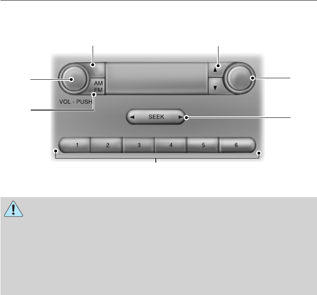
AM/FM
WARNING: Driving while distracted can result in loss of vehicle
control, crash and injury. We strongly recommend that you use
extreme caution when using any device that may take your focus off
the road. Your primary responsibility is the safe operation of your
vehicle. We recommend against the use of any hand-held device while
driving and encourage the use of voice-operated systems when possible.
Make sure you are aware of all applicable local laws that may affect the
use of electronic devices while driving.
A. CLK: Press this button to switch the display between the clock and
radio frequency. To set the time:
1. Press and hold CLK until the hours start to flash.
2. Press the arrow buttons to adjust the hours. Repeat Steps 1 and 2 to
set the minutes.
3. Press CLK again to exit clock mode.
B. Tune: Press these arrow buttons to manually search through the radio
frequency band. Press and hold for a fast search. In AUDIO mode, press
the buttons to adjust different sound settings.
C. AUDIO: Press this button to access settings for Treble, Middle, Bass,
Fade and Balance.
D. SEEK: Press this button to go to the previous or next strong station
on the frequency band.
CLK
AUDIO C
E
G
F
B
A
D
Audio System 79
2013 F-650/750 (f67)
Owners Guide gf, 2nd Printing, March 2013
USA (fus)
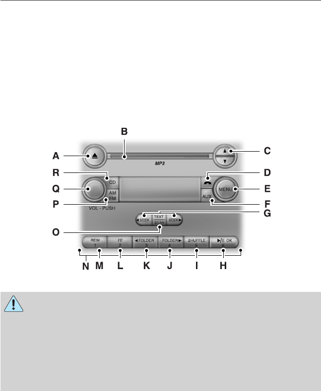
E. Memory presets: Store your favorite radio stations. To store a radio
station, tune to the station, then press and hold a preset button until
sound returns.
F. AM/FM: Press this button to select a frequency band.
G. VOL-PUSH:
•Press this button to switch the system off and on.
•Turn the control to adjust the volume.
AM/FM/CD WITH SYNC®
WARNING: Driving while distracted can result in loss of vehicle
control, crash and injury. We strongly recommend that you use
extreme caution when using any device that may take your focus off
the road. Your primary responsibility is the safe operation of your
vehicle. We recommend against the use of any hand-held device while
driving and encourage the use of voice-operated systems when possible.
Make sure you are aware of all applicable local laws that may affect the
use of electronic devices while driving.
A. Eject: Press this button to eject a CD.
B. CD slot: Insert a CD.
C. Tune: Press this button to manually search through the radio
frequency band. Press and hold for a fast search.
80 Audio System
2013 F-650/750 (f67)
Owners Guide gf, 2nd Printing, March 2013
USA (fus)

D. Phone: Press this button to access the phone features of the SYNC®
system. See the SYNC® chapter for more information.
E. MENU: Press this button to access different audio system features.
•If your vehicle is equipped with satellite radio, you can access
different menus by pressing OK.
•Set the time by pressing MENU until SET HOURS or SET
MINUTES appears and using the arrow buttons to adjust the time.
•Set the strongest stations on the radio frequency by pressing MENU
until AUTOSET appears. AUTOSET does not override your original
presets.
•RBDS displays text transmitted by certain radio stations and
searches for music categories. To search for music categories, turn on
RBDS (by using the SEEK buttons when RBDS ON/OFF appears).
Press the up and down arrow buttons to scroll through categories,
then use the SEEK buttons to begin the search.
•SPEEDVOL (speed compensated volume) allows you to adjust radio
volume to compensate for noise levels when vehicle speed increases.
•Track/Folder is only available on MP3 files when in CD mode. In
track mode, pressing the SEEK arrows allows you to scroll through
all the tracks on the disc. In folder mode, pressing the SEEK arrows
allows you to scroll through all the tracks within the selected folder.
Press the FOLDER buttons to access other folders.
•COMPRESS (Compression) is only available in CD and MP3 modes.
Switching compression on brings the soft and loud passages together
for a more consistent listening level. Use the SEEK buttons and up
and down arrow buttons to switch it on and off.
F. AUX: Press this button to access the media features of the SYNC®
system. See the SYNC® chapter for more information.
G. SEEK:
•In radio mode, press and release these buttons to go to the next (or
previous) preset radio station or disc track.
•In CD and MP3 modes, press these buttons to select the next (or
previous) track, or press and hold to advance (or reverse) within the
same track.
H. Play, Pause and OK:
•Play and Pause allow you to play or pause a track when listening to a
CD.
•OK allows you to confirm commands with phone and media features
of the SYNC system. See the SYNC® chapter for more information.
I. SHUFFLE: Play music on the selected CD or MP3 folder in random
order.
Audio System 81
2013 F-650/750 (f67)
Owners Guide gf, 2nd Printing, March 2013
USA (fus)

J. Folder: Press this button to access the next folder on an MP3 disc.
K. Folder: Press this button to access the previous folder on an MP3
disc.
L. FF: Press this button to manually fast forward in a CD track or MP3
file.
M. REW: Press this button to manually rewind in a CD track or MP3 file.
N. Memory presets: Store your favorite radio stations. To store a radio
station, tune to the station, then press and hold a preset button until
sound returns.
O. TEXT/SCAN:
•In radio, CD and MP3 modes, press and hold to hear a brief sampling
of radio stations, CD tracks or MP3 files.
•In CD and MP3 modes, press and release to display track title, artist
name and disc title.
Note: In text mode, sometimes the display requires additional text to
show. When the</>indicatorison,pressTEXT and then use the
SEEK buttons to view the additional display text.
P. AM/FM: Press this button to select a frequency band.
Q. VOL-PUSH:
•Press this button to switch the system off and on.
•Turn it to adjust the volume.
R. CD: Press this button to enter CD or MP3 mode.
AUXILIARY INPUT JACK
WARNING: Driving while distracted can result in loss of vehicle
control, crash and injury. We strongly recommend that you use
extreme caution when using any device that may take your focus off
the road. Your primary responsibility is the safe operation of your
vehicle. We recommend against the use of any hand-held device while
driving and encourage the use of voice-operated systems when possible.
Make sure you are aware of all applicable local laws that may affect the
use of electronic devices while driving.
WARNING: For safety reasons, do not connect or adjust the
settings on your portable music player while your vehicle is
moving.
82 Audio System
2013 F-650/750 (f67)
Owners Guide gf, 2nd Printing, March 2013
USA (fus)
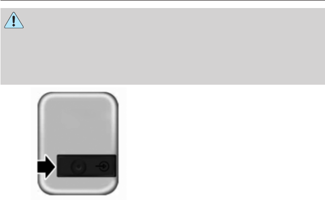
WARNING: Store the portable music player in a secure location,
such as the center console or the glove box, when your vehicle is
moving. Hard objects may become projectiles in a crash or sudden stop,
which may increase the risk of serious injury. The audio extension cable
must be long enough to allow the portable music player to be safely
stored while your vehicle is moving.
The auxiliary input jack allows you
to connect and play music from
your portable music player through
your vehicle speakers. You can use
any portable music player designed
for use with headphones. Your audio
extension cable must have male
1
⁄
8
-inch (3.5 millimeter) connectors
at each end.
1. Switch off the engine, radio and portable music player. Set the
parking brake and put the transmission in position P.
2. Plug the extension cable from the portable music player into the
auxiliary input jack.
3. Switch the radio on. Select either a tuned FM station or a CD.
4. Adjust the volume as desired.
5. Switch your portable music player on and adjust its volume to half its
maximum level.
6. Press AUX until LINE or LINE IN appears in the display. You
should hear music from your device even if it is low.
7. Adjust the volume on your portable music player until it reaches the
volume level of the FM station or CD. Do this by switching back and
forth between the AUX and FM or CD controls.
Audio System 83
2013 F-650/750 (f67)
Owners Guide gf, 2nd Printing, March 2013
USA (fus)
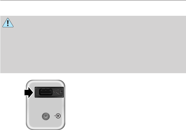
USB PORT (IF EQUIPPED)
WARNING: Driving while distracted can result in loss of vehicle
control, crash and injury. We strongly recommend that you use
extreme caution when using any device that may take your focus off
the road. Your primary responsibility is the safe operation of your
vehicle. We recommend against the use of any hand-held device while
driving and encourage the use of voice-operated systems when possible.
Make sure you are aware of all applicable local laws that may affect the
use of electronic devices while driving.
The USB port allows you to plug in
media playing devices, memory
sticks and charge devices (if
supported). See the SYNC chapter
for more information.
SATELLITE RADIO INFORMATION (IF EQUIPPED)
Satellite Radio Channels
Sirius broadcasts a variety of music, news, sports, weather, traffic and
entertainment satellite radio channels. For more information and a
complete list of Sirius satellite radio channels, visit www.siriusxm.com in
the United States, www.sirius.ca in Canada, or call Sirius at
1–888–539–7474.
Note: This receiver includes the eCos real-time operating system. eCos
is published under the eCos License.
84 Audio System
2013 F-650/750 (f67)
Owners Guide gf, 2nd Printing, March 2013
USA (fus)
Satellite Radio Reception Factors
Potential satellite radio reception issues
Antenna
obstructions
For optimal reception performance, keep the
antenna clear of snow and ice build-up and
keep luggage and other material as far away
from the antenna as possible.
Terrain Hills, mountains, tall buildings, bridges,
tunnels, freeway overpasses, parking garages,
dense tree foliage and thunderstorms can
interfere with your reception.
Station overload When you pass a ground-based
broadcast-repeating tower, a stronger signal
may overtake a weaker one and the audio
system may mute.
Satellite radio signal
interference
Your display may show ACQUIRING...to
indicate the interference and the audio
system may mute.
Sirius Satellite Radio Service
Note: Sirius reserves the unrestricted right to change, rearrange, add or
delete programming including canceling, moving or adding particular
channels, and its prices, at any time, with or without notice to you. Ford
Motor Company shall not be responsible for any such programming
changes.
Sirius satellite radio is a
subscription-based satellite radio
service that broadcasts a variety of
music, sports, news, weather, traffic
and entertainment programming.
Your factory-installed Sirius satellite
radio system includes hardware and
a limited subscription term which begins on the date of sale or lease of
your vehicle. See an authorized dealer for availability.
For more information on extended subscription terms (a service fee is
required), the online media player and a complete list of Sirius satellite
radio channels, and other features, please visit www.siriusxm.com in the
United States, www.sirius.ca in Canada, or call Sirius at 1–888–539–7474.
Audio System 85
2013 F-650/750 (f67)
Owners Guide gf, 2nd Printing, March 2013
USA (fus)

Satellite Radio Electronic Serial Number (ESN)
You need your ESN to activate, modify or track your satellite radio
account. When in satellite radio mode, you can view this number by
pressing SIRIUS and memory preset 1 at the same time. To access your
ESN, press the bottom left corner of the touchscreen, then SIRIUS >
Options.
Troubleshooting
Radio display Condition Possible action
Acquiring Radio requires more
than two seconds to
produce audio for the
selected channel.
No action required.
This message should
disappear shortly.
Sat Fault/SIRIUS
system failure
There is an internal
module or system
failure present.
If this message does
not clear shortly, or
with an ignition key
cycle, your receiver
may have a fault. See
an authorized dealer
for service.
Invalid Channel The channel is no
longer available.
Tune to another
channel or choose
another preset.
Unsubscribed Channel Your subscription does
not include this
channel.
Contact Sirius at
1–888–539–7474 to
subscribe to the
channel, or tune to
another channel.
No Signal The signal is lost from
the Sirius satellite or
Sirius tower to your
vehicle antenna.
The signal is blocked.
When you move into
an open area, the
signal should return.
Updating Update of channel
programming in
progress.
No action required.
The process may take
up to three minutes.
86 Audio System
2013 F-650/750 (f67)
Owners Guide gf, 2nd Printing, March 2013
USA (fus)

Radio display Condition Possible action
Call SIRIUS
1–888–539–7474
Your satellite service is
no longer available.
Call Sirius at
1–888–539–7474 to
resolve subscription
issues.
None Found. Check
Channel Guide.
All the channels in the
selected category are
either skipped or
locked.
Use the channel guide
to turn off the Lock or
Skip function on that
station.
Subscription Updated Sirius has updated the
channels available for
your vehicle.
No action required.
Audio System 87
2013 F-650/750 (f67)
Owners Guide gf, 2nd Printing, March 2013
USA (fus)
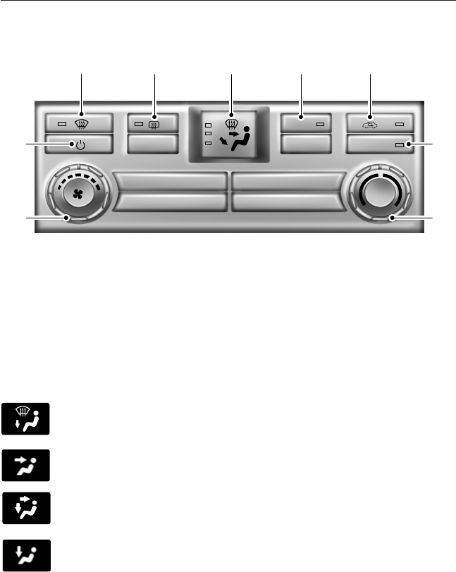
MANUAL CLIMATE SYSTEM
A. Defrost: Distributes air through the windshield defroster vents and
demister vents. This setting can also be used to defog and clear the
windshield of a thin covering of ice.
B. Heated mirrors: Turns the heated mirrors on and off. See Heated
mirrors later in this chapter for more information.
C. Air distribution control: Press to set the air distribution to a
position listed below:
Distributes air through the windshield defroster vents, demister
vents and floor vents.
Distributes air through the instrument panel vents.
Distributes air through the instrument panel vents, floor vents,
and demister vents.
Distributes air through the floor vents.
A/C
MAX A/C
A B D E
F
G
I
H
C
88 Climate Control
2013 F-650/750 (f67)
Owners Guide gf, 2nd Printing, March 2013
USA (fus)

D. A/C: Press to turn air conditioning on or off. Air conditioning cools
the vehicle using outside air. To improve air conditioning when starting
your vehicle, drive with the windows slightly open for two to three
minutes.
E. Recirculated air: Press to switch between outside air and
recirculated air. When the LED on the button is lit, the air currently in
the passenger compartment is being recirculated. Using recirculated air
can reduce the time needed to cool the interior and reduce unwanted
odors from entering your vehicle.
Note: For better cooling in hot conditions, recirculated air automatically
engages when the air distribution control is in Panel or Panel/Floor
modes and the air conditioning is on. You can switch to fresh air by
pressing the recirculated air button again.
F. MAX A/C: Distributes recirculated air through the instrument panel
vents to cool the vehicle. This position is more economical and efficient
than normal A/C.
G. Temperature control: Controls the temperature of the air circulated
in your vehicle. Turn to select the desired temperature.
H. Fan speed control: Controls the volume of air circulated in your
vehicle. Turn to select the desired fan speed or switch off. If you switch
the fan off, the windshield may fog up.
I. Power: Press to turn the system on and off. When the system is off,
outside air is prevented from entering the vehicle.
GENERAL OPERATING TIPS
•To reduce fog build-up on the windshield during humid weather,
select Defrost. Temperature and fan speed can also be increased to
improve clearing.
•To reduce humidity build-up inside the vehicle, do not drive with the
system off or with recirculated air engaged.
•Do not put objects under the front seats that interfere with the
airflow to the back seats.
•Remove any snow, ice or leaves from the air intake area at the base
of the windshield.
Cooling the interior quickly:
1. Adjust the fan speed to the highest speed setting initially and then
adjust it to suit the desired comfort level.
2. Adjust the temperature control to the lowest temperature setting.
3. Adjust the air distribution control to the MAX A/C position.
Climate Control 89
2013 F-650/750 (f67)
Owners Guide gf, 2nd Printing, March 2013
USA (fus)

Recommended settings for cooling:
•Adjust the air distribution control to the A/C position.
If your vehicle is stationary for extended periods during extreme high
ambient temperatures:
•Select the MAX A/C position.
Gas engines: If your vehicle is stationary for long periods of time in
high ambient temperature conditions, your climate control system may
automatically switch from fresh air mode to recirculation mode. This is
normal system operation as it provides protection of the air conditioning
compressor (and related parts). It is recommended that you allow the
system to remain in this mode if it has switched. The system reverts
back to fresh air mode when conditions allow.
For maximum cooling performance, turn the air distribution control to
MAX A/C.
To aid in side window defogging/demisting in cold weather:
1. Select Panel/Floor.
2. Select A/C.
3. Adjust the temperature control to maintain comfort.
4. Set the fan speed to the highest setting.
5. Direct the outer instrument panel vents toward the side windows.
6. To increase airflow to the outer instrument panel vents, close the
vents located in the middle of the instrument panel.
HEATED MIRRORS (IF EQUIPPED)
Note: Do not remove ice from the mirrors with a scraper or attempt to
readjust the mirror glass if it is frozen in place. These actions could
cause damage to the glass and mirrors.
Note: Do not clean the housing or glass of any mirror with harsh
abrasives, fuel or other petroleum-based cleaning products.
Both mirrors are heated to remove ice, mist and fog when the heated
mirror button is pressed.
90 Climate Control
2013 F-650/750 (f67)
Owners Guide gf, 2nd Printing, March 2013
USA (fus)
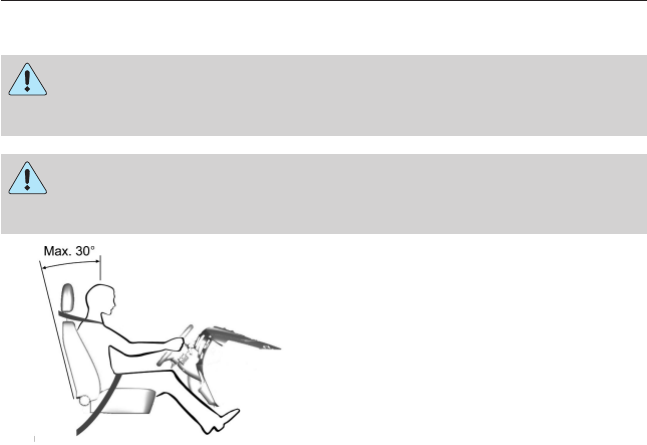
SITTING IN THE CORRECT POSITION
WARNING: Do not recline the seat back as this can cause the
occupant to slide under the seat’s safety belt, resulting in severe
personal injury in the event of a crash.
WARNING: Do not place objects higher than the seat backs to
reduce the risk of injury in a crash or during heavy braking or
when stopping suddenly.
When you use them properly, the
seat, head restraint and safety belt
provide optimum protection in the
event of a crash. We recommend
that you follow these guidelines:
•Do not recline the seat back more than 30 degrees from vertical.
•Sit in an upright position with the base of your spine as far back as
possible.
•Adjust the head restraint so that the top of it is level with the top of
your head and as far forward as possible, remaining comfortable.
•Keep sufficient distance between yourself and the steering wheel. We
recommend a minimum of 10 inches (250 millimeters) between your
breastbone and the center of the steering wheel.
•Hold the steering wheel with your arms slightly bent.
•Bend your legs slightly so that you can press the pedals fully.
•Position the shoulder strap of the safety belt over the center of your
shoulder and position the lap strap tightly across your hips.
Make sure that your driving position is comfortable and that you can
maintain full control of your vehicle.
Seats 91
2013 F-650/750 (f67)
Owners Guide gf, 2nd Printing, March 2013
USA (fus)
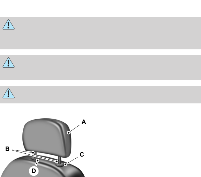
HEAD RESTRAINTS
WARNING: To minimize the risk of neck injury in the event of a
crash, you and the passenger occupants should not sit in or
operate the vehicle, until the head restraint is placed in its proper
position. Never adjust the head restraint while the vehicle is in motion.
WARNING: The adjustable head restraint is a safety device.
Whenever possible it should be installed and properly adjusted
when the seat is occupied.
WARNING: Install the head restraint properly to minimize the
risk of neck injury in the event of a crash.
Front Seat Head Restraints
The head restraints consist of:
A. An energy absorbing head restraint
B. Two steel stems
C. Guide sleeve adjust and release button
D. Guide sleeve unlock and remove button
Note: Adjust the seat back to an upright driving position before
adjusting any head restraint. Properly adjust the head restraint so that
the top of the head restraint is even with the top of your head and
positioned as close as possible to the back of your head. For occupants
of extremely tall stature, adjust the head restraint to its full up position.
92 Seats
2013 F-650/750 (f67)
Owners Guide gf, 2nd Printing, March 2013
USA (fus)
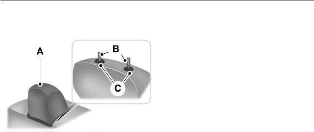
Front Row Center, Outboard (Crew Cab), and Rear Seat Center
(Crew Cab) Head Restraints
Your vehicle may be equipped with
head restraints that are
non-adjustable.
The non-adjustable head restraints consist of:
A. An energy absorbing head restraint
B. Two steel stems
C. Guide sleeve unlock and remove buttons
Rear Head Restraints (SuperCab)
The SuperCab has rear outboard head restraints that are not removable
and are bolted to the back wall.
Adjusting the Head Restraints
Raise
Pull up the head restraint.
Lower
1. Press and hold button C.
2. Push down on the head restraint.
Remove - Front Seat Head Restraints
1. Pull up the head restraint until it reaches the highest adjustment
position.
2. Press and hold buttons C and D.
3. Pull up the head restraint.
Seats 93
2013 F-650/750 (f67)
Owners Guide gf, 2nd Printing, March 2013
USA (fus)
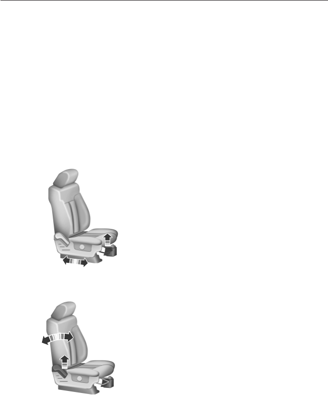
Remove - Front Row Center, Outboard (Crew Cab), and Rear Seat
Center (Crew Cab) Head Restraints
1. Pull up the head restraint until it reaches the highest adjustment
position.
2. Press and hold buttons C.
3. Pull up the head restraint.
Reinstall
Align the steel stems into the guide sleeves and push the head restraint
down until it locks.
MANUAL SEATS
Moving the Seats Backward and Forward
Recline Adjustment
94 Seats
2013 F-650/750 (f67)
Owners Guide gf, 2nd Printing, March 2013
USA (fus)
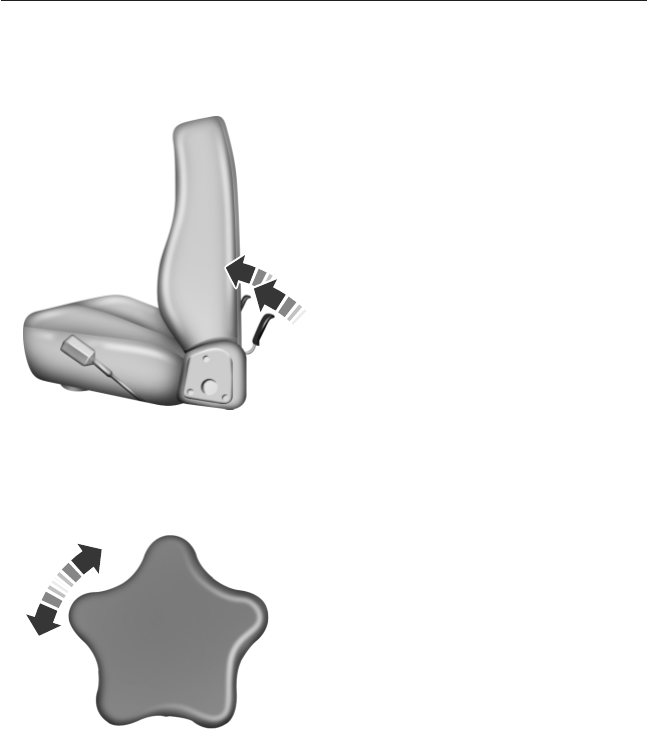
Tilting the Seat Back Forward (Two-passenger Bench Seat)
Manual Lumbar (If Equipped)
The lumbar support control is
located on the outboard side of the
seat. Turn the control to adjust your
support.
Seats 95
2013 F-650/750 (f67)
Owners Guide gf, 2nd Printing, March 2013
USA (fus)
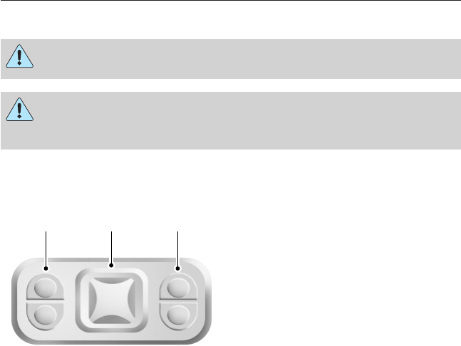
POWER SEATS
WARNING: Never adjust the driver’s seat when the vehicle is
moving.
WARNING: To reduce the risk of excess slack in the belt
system, always adjust the seat height before fastening the seat
belt.
Non Air-Ride Seat
The control is located on the outboard side of the seat cushion.
•Press A to raise or lower the
front portion of the seat cushion.
•Press B to move the seat
forward, backward, up or down.
•Press C to raise or lower the
rear portion of the seat cushion.
A B C
96 Seats
2013 F-650/750 (f67)
Owners Guide gf, 2nd Printing, March 2013
USA (fus)
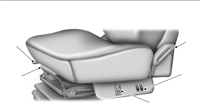
Air-Ride Seat
A. Recline: Lift the handle to adjust the angle of the seat back.
B. Power lumbar:
•Press the top of the forward control to inflate the lower lumbar
support.
•Press the bottom of the forward control to deflate the lower lumbar
support.
•Press the top of the rear control to inflate the upper lumbar support.
•Press the bottom of the rear control to deflate the upper lumbar
support.
C. Seat height adjuster:
•Pull the control up to raise the seat.
•Push the control down to lower the seat.
D. Seat adjuster:
•Lift the bar up to move the seat forward or backward.
•Release the bar to lock the seat in position.
E. Chugger option: Dampens road vibrations and allows the seat to
move with the driver when unlocked.
•To unlock, sit in the seat and slide the tab away to the right.
•To lock, sit in the seat and slide the tab to the left.
E
D
C
B
A
Seats 97
2013 F-650/750 (f67)
Owners Guide gf, 2nd Printing, March 2013
USA (fus)
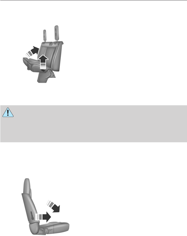
REAR SEATS
Folding Up the Rear Seats (SuperCab)
1. Pull the control to release the
seat cushion.
2. Rotate the seat cushion up until
it locks into the vertical storage
position.
Returning the Seat to the Seating Position
WARNING: Make sure that cargo or any objects are not trapped
underneath the seat cushion before returning the seat cushion to
its original position, and that the seat cushion locks into place. Failure
to do so may prevent the seat from operating properly in the event of a
crash, which could increase the risk of serious injury.
1. Pull the control on the side of the seat to release the seat cushion
from the storage position.
2. Push the seat cushion down until it locks into the horizontal position.
Folding the Rear Seat Back (Crew Cab)
1. Pull forward on the control to
fold down the seat back.
2. Pull down on the handle and lift
up on the seat back to return it
to the original position.
98 Seats
2013 F-650/750 (f67)
Owners Guide gf, 2nd Printing, March 2013
USA (fus)
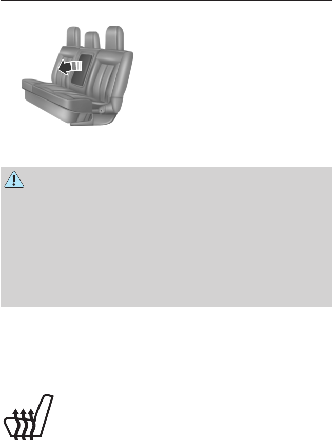
REAR SEAT ARMREST (IF EQUIPPED)
To use the armrest, rotate it
forward from the seat back.
HEATED SEATS (IF EQUIPPED)
WARNING: Persons who are unable to feel pain to the skin
because of advanced age, chronic illness, diabetes, spinal cord
injury, medication, alcohol use, exhaustion, or other physical conditions,
must exercise care when using the seat heater. The seat heater may
cause burns even at low temperatures, especially if used for long
periods of time. Do not place anything on the seat that insulates against
heat, such as a blanket or cushion, because this may cause the seat
heater to overheat. Do not puncture the seat with pins, needles, or
other pointed objects because this may damage the heating element
which may cause the seat heater to overheat. An overheated seat may
cause serious personal injury.
Note: Do not do the following:
•Place heavy objects on the seat.
•Operate the seat heater if water or any other liquid is spilled on the
seat. Allow the seat to dry thoroughly.
•Operate the heated seats unless the engine is running. Doing so could
drain your vehicle’s battery.
Press to cycle through the various heat settings and off.
Warmer settings are indicated by more indicator lights.
Seats 99
2013 F-650/750 (f67)
Owners Guide gf, 2nd Printing, March 2013
USA (fus)
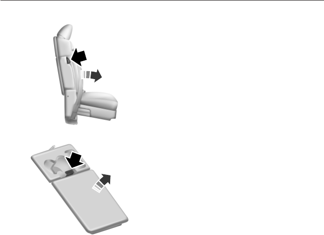
FRONT SEAT ARMREST (IF EQUIPPED)
To release the armrest and gain
access to the cupholders and seat
back storage bin, press the button
on the right-hand side of the seat
and pull the seat back down.
Pull up on the tab to open the
storage bin.
Lift up on the seat back to return it to the upright position.
100 Seats
2013 F-650/750 (f67)
Owners Guide gf, 2nd Printing, March 2013
USA (fus)

AUXILIARY POWER POINTS
WARNING: Do not plug optional electrical accessories into the
cigarette lighter socket (if equipped). Improper use of the lighter
can cause damage not covered by your warranty, and can result in fire
or serious injury.
Note: If used when the engine is not running, the battery will discharge.
There may be insufficient power to restart your engine.
Note: Do not insert objects other than an accessory plug into the power
point. This will damage the outlet and blow the fuse.
Note: Do not hang any type of accessory or accessory bracket from the
plug.
Note: Do not use the power point over the vehicle capacity of 12–volt
DC 180 watts or a fuse may blow.
Note: Do not use the power point for operating a cigarette lighter
element.
Note: Improper use of the power outlet can cause damage not covered
by your warranty.
Note: Always keep the power point caps closed when not in use.
Run the engine for full capacity use of the power point. To prevent the
battery from being discharged:
•Do not use the power point longer than necessary when the engine is
not running.
•Do not leave devices plugged in overnight or when the vehicle is
parked for extended periods.
Locations
Power points may be found:
•on the instrument panel (two locations).
•inside the center console storage compartment (if equipped).
•on the rear of the center console (if equipped).
•inside the 20-percent front seat console (if equipped).
•inside the rear under seat storage compartment (if equipped).
Auxiliary Power Points 101
2013 F-650/750 (f67)
Owners Guide gf, 2nd Printing, March 2013
USA (fus)

GENERAL INFORMATION
WARNING: Extended idling at high engine speeds can produce
very high temperatures in the engine and exhaust system,
creating the risk of fire or other damage.
WARNING: Do not park, idle, or drive your vehicle on dry grass
or other dry ground cover. The emission system heats up the
engine compartment and exhaust system, which can start a fire.
WARNING: Do not start your vehicle in a closed garage or in
other enclosed areas. Exhaust fumes can be toxic. Always open
the garage door before you start the engine.
WARNING: If you smell exhaust fumes inside your vehicle, have
your vehicle checked by an authorized dealer immediately. Do
not drive if you smell exhaust fumes.
If you disconnect the battery, your vehicle may exhibit some unusual
driving characteristics for approximately five miles (eight kilometers)
after you connect it. This is because the engine management system
must realign itself with the engine. You may disregard any unusual
driving characteristics during this period.
The powertrain control system meets all Canadian interference-causing
equipment standard requirements regulating the impulse electrical field
strength of radio noise.
When starting your vehicle, avoid pressing the accelerator pedal before
and during operation. Only use the accelerator pedal when you have
difficulty starting the engine.
If your vehicle is operated in a heavy snow storm or blowing snow
conditions, the engine air induction may become partially clogged with
snow or ice. If this occurs, the engine may experience a significant
reduction in power output. At the earliest opportunity, clear all the snow
or ice away from the air induction inlet.
102 Starting and Stopping the Engine
2013 F-650/750 (f67)
Owners Guide gf, 2nd Printing, March 2013
USA (fus)

IGNITION SWITCH
Note: When you switch the ignition off and leave your vehicle, do not
leave your key in the ignition. This could discharge your vehicle battery.
A. Accessory: Allows the electrical accessories, such as the radio, to
operate while the engine is not running.
B. Lock: Locks the automatic transmission gearshift lever, if equipped
with position P, and allows key removal.
C. Off: Shuts off the engine and all accessories.
D. On: All electrical circuits are operational. Warning lights are
illuminated. Key position when driving.
E. Start: Cranks the engine. Release the key as soon as the engine
starts.
STARTING A GASOLINE ENGINE
When the engine starts, the idle RPM runs faster to warm the engine. If
the engine idle speed does not slow down automatically, have the vehicle
checked.
Before starting the vehicle:
•Make sure all occupants buckle their safety belts.
•Make sure the headlamps and electrical accessories are off.
•Make sure the parking brake is set.
•Make sure the gearshift is in position P.
•Turn the key to on without turning the key to start.
Some warning lights briefly illuminate.
Note: Do not touch the accelerator pedal.
1. Fully press the brake pedal.
D
E
C
B
A
Starting and Stopping the Engine 103
2013 F-650/750 (f67)
Owners Guide gf, 2nd Printing, March 2013
USA (fus)

2. Turn the key to start the engine. The engine may continue cranking
for up to 15 seconds or until the vehicle starts.
Note: If the engine does not start on the first try, wait for a short period
of time and try again.
If you have difficulty starting the engine when the temperature is below
-13°F (-25°C), press the accelerator pedal slightly and try again.
If the engine does not start after three attempts, wait 10 seconds and
follow this flooded engine procedure.
1. Select position Por N.
2. Fully press the accelerator pedal and hold it there.
3. Fully press the brake pedal.
4. Start the engine.
Guarding Against Exhaust Fumes
WARNING: If you smell exhaust fumes inside your vehicle, have
this checked immediately. Do not drive your vehicle if you smell
exhaust fumes. Carbon monoxide is present in exhaust fumes. Take
precautions to avoid its dangerous effects.
Important Ventilating Information
If you stop your vehicle and leave the engine idling for long periods of
time, we recommend that you do one of the following:
•Open the windows at least 1 inch (2.5 centimeters).
•Set your climate control to outside air.
104 Starting and Stopping the Engine
2013 F-650/750 (f67)
Owners Guide gf, 2nd Printing, March 2013
USA (fus)
STARTING A DIESEL ENGINE
WARNING: Operation of a diesel engine near flammable vapors
in the air may cause the engine speed to increase uncontrollably
and over speed. If this situation occurs, mechanical damage, fire,
explosion, personal injury or death could result. Turning off the
ignition key does not slow or stop the engine due to uncontrollable
fueling of the engine through flammable vapors being drawn into
the engine air inlet. Operation of components such as starter,
alternator, electric motors, etc. and static electricity could also ignite
flammable vapors.
Do not operate the truck in the possible presence of flammable vapors
unless both a complete hazard analysis is performed and necessary
additional safety processes and/or equipment such as vapor testing, air
intake shutoff devices, ventilation, etc. are utilized. The operator is
responsible for using those processes and/or equipment to ensure that
the diesel engine and all other components on the truck can be
operated safely under the specific conditions and hazards that may be
encountered.
WARNING: If equipped with an air intake heater, DO NOT use
ether or any other starting fluids. The use of starting fluids
(ether) in an engine equipped with an air intake heater could cause an
explosion and result in property damage and/or personal injury.
Switch the ignition on and wait until the glow plug indicator
goes off.
Note: You can only operate the starter for a maximum of 30 seconds at
a time. Allow two minutes before cranking the starter again.
Note: On some engines, the glow plug indicator illuminates after the
engine starts. Allow the engine to idle about three minutes, or until the
engine coolant temperature gauge begins to rise. Maintain idle speed
until the glow plug indicator goes off. Operating the engine at higher
speeds reduces the effectiveness of the air inlet heater.
Note: When starting a cold engine, increase the engine RPM slowly to
make sure adequate lubrication is available to the bearings.
Starting and Stopping the Engine 105
2013 F-650/750 (f67)
Owners Guide gf, 2nd Printing, March 2013
USA (fus)

Note: Do not increase engine speed until the oil pressure gauge
indicates normal pressure. This should be indicated on the gauge within
15 seconds after starting.
Note: Idle the engine for three to five minutes before operating with a
full load.
Note: Try to limit engine idle to 10 minutes. Excessive idling reduces
fuel economy.
Vehicles with a Manual Transmission
Note: Do not touch the accelerator pedal.
1. Fully press the clutch pedal.
2. Start the engine.
Vehicles with an Automatic Transmission
Note: Do not touch the accelerator pedal.
1. Select position N, or P(if equipped with a Park position).
2. Fully press the brake pedal.
3. Start the engine.
Starting the Engine with the Vehicle on a Steep Grade
When starting a diesel engine when the loaded vehicle is on a grade, the
engine RPM starts to fall slightly when the clutch is engaged. Do not
disengage the clutch and try to increase engine RPM as this may damage
driveline components. The engine recovers as the vehicle begins moving.
DIESEL PARTICULATE FILTER (DPF)
WARNING: The normal operating temperature of the exhaust
system is very high. Never work around, or attempt to repair, any
part of the exhaust system until it has cooled. Use special care when
working around the diesel particulate filter. The DPF heats up to a high
temperature after only a short period of engine operation, and can
remain hot even after the engine is turned off. Failure to follow these
instructions may result in serious personal injury.
Your vehicle is equipped with a diesel particulate filter (DPF), as part of
the after-treatment exhaust system, to trap soot and other large particles
produced by the engine combustion process. The soot that accumulates
in the filter must be periodically reduced to ash to prevent excessive
exhaust restriction. The soot reduction process, also known as “filter
regeneration,” is generally performed automatically by your engine and
after-treatment system.
106 Starting and Stopping the Engine
2013 F-650/750 (f67)
Owners Guide gf, 2nd Printing, March 2013
USA (fus)
Regeneration
Unlike a normal filter which requires periodic replacement, the DPF has
been designed to regenerate, or clean itself to maintain operating
efficiency. The regeneration process takes place automatically. A small
increase in engine/turbo sound-level is normal during filter regeneration.
However, some driving conditions mean that you may need to support
the regeneration process:
•Operating in stop-and-go traffic or maintaining low speeds as in city
or delivery driving
•Frequent engine starting and stopping
•Relatively light vehicle payload
•Regular operation in cold ambient temperatures (i.e., below 0°F
[-18°C]).
Diesel Particulate Filter Four–level Loading Chart
Level/Lamp status Filter status Requested action
Level 1
solid
Regeneration required. Drive on the highway
at highway speeds OR
start parked
regeneration to
prevent loss of engine
performance.
Level 2
flashing
(once per second)
Nearly full. Engine
performance is limited.
Level 3
flashing + solid
Full. Engine
performance is
increasingly limited.
Perform parked
regeneration to
prevent loss of engine
performance.
Level 4
solid
Over full. Engine
performance is highly
limited. Continued
operation may result
in irreparable damage
to the filter.
Pull vehicle safely off
roadway, turn on
hazard flashers and
shut down engine as
soon as possible. Seek
service immediately.
Starting and Stopping the Engine 107
2013 F-650/750 (f67)
Owners Guide gf, 2nd Printing, March 2013
USA (fus)

Instrument cluster lamp(s) illuminates or flashes when operator
assistance is required. In addition, engine performance becomes
increasingly limited above Level 1.
At Levels 1 and 2, two courses of action may be taken by the operator to
facilitate filter regeneration:
1. The vehicle may be driven on the highway at highway speeds.
2. The operator may perform a parked regeneration by following the
steps in Parked regeneration.
At Level 3, performing a parked regeneration is the only available course
of action (short of professional servicing) available to the operator for
regenerating the filter. At Level 4, professional servicing is the only way
to regenerate the filter.
Parked Regeneration
WARNING: When performing the parked regeneration
procedure, make certain the vehicle is safely off the roadway, and
the exhaust system is away from people, or any flammable materials,
vapors, or structures. Engine speed may increase during parked
regeneration.
Note: Parked regeneration is only available when the DPF lamp on the
instrument cluster is illuminated (solid or flashing).
1. Bring the vehicle to a complete stop on level ground and safely off
the road with the exhaust system away from people, flammable
materials, vapors or structures. Ford recommends that you perform a
walk-around before beginning a parked regeneration.
2. If your vehicle is equipped with an automatic transmission and a
steering column shift lever, place the transmission in position P.
Otherwise, place the transmission in position N.
3. Remove your feet from the accelerator pedal and clutch pedal
(if equipped).
4. Set the parking brake.
5. Within five seconds of setting the parking brake, remove your
foot from the service brake pedal.
The engine speed may increase slightly. To allow parked regeneration to
continue uninterrupted:
1. The vehicle must remain parked.
2. The transmission must remain in position Por N(as previously
described in Step 2).
108 Starting and Stopping the Engine
2013 F-650/750 (f67)
Owners Guide gf, 2nd Printing, March 2013
USA (fus)

3. The accelerator pedal, service brake pedal, and clutch pedal
(if equipped) must not be pressed.
4. The parking brake must remain set.
On average (depending on filter level and other factors), the process
takes 20–30 minutes to complete. The DPF lamp turns off when the
process is complete. Repeat Steps 1–5, if parked regeneration is
interrupted.
To Discontinue Parked Regeneration
Press any of the floor pedals to discontinue parked regeneration.
Maintenance and Service
The DPF is designed to retain a relatively large amount of residual ash
and provide many miles and hours of maintenance-free operation. At
some point, generally beyond 150000 miles (240000 kilometers) or
5000 hours of operation (whichever comes first), the DPF requires
professional cleaning to remove the accumulated ash.
The exact number of miles or hours of operation varies greatly
depending upon vehicle and engine loading and operating conditions, ash
content of the engine oil, and quality of the diesel fuel used in your
truck. Adhering to your engine manufacturer’s recommended oil and fuel
specifications maximizes the miles and hours of operation before a DPF
professional cleaning is required. See your engine manufacturer’s owner’s
manual for more details regarding recommended maintenance and
service of your DPF.
Exhaust Outlet Assembly
WARNING: The normal operating temperature of the exhaust
system is very high. Never work around or attempt to repair any
part of the exhaust system until it has cooled. Failure to follow these
instructions may result in serious personal injury.
Note: Do not modify or remove this device. Modification of the system
or additions of aftermarket devices can reduce the effectiveness of the
system, as well as cause damage to the exhaust system or engine. Any
modifications may also invalidate the vehicle and/or engine warranties.
See your warranty information.
Note: Blocked or plugged holes or modification to, or removal of, the
outlet assembly could result in elevated exhaust temperatures which may
result in vehicle or property damage or personal injury.
Starting and Stopping the Engine 109
2013 F-650/750 (f67)
Owners Guide gf, 2nd Printing, March 2013
USA (fus)

The exhaust outlet assembly on your vehicle is a uniquely functioning
device that accompanies the DPF assembly. It is designed to help control
the temperature of the exhaust during the DPF regeneration process.
The inlet holes in the side of the assembly are functional. These holes
allow outside air to be drawn into the outlet assembly. The holes need to
be kept clear of mud and other foreign material to maintain proper
functionality of the system. One way to keep the holes clear is to spray
the outlet assembly with a hose when washing the vehicle. Failure to
keep the functional holes clear of foreign material may result in the holes
becoming blocked or plugged.
SWITCHING OFF A DIESEL ENGINE
Allow the engine to idle for three to five minutes before shutting it
down; the larger the engine, the greater the need for this idling period.
Note: Try to limit engine idle to 10 minutes. Excessive idling reduces
fuel economy.
ENGINE AUTOMATIC SHUTDOWN (IF EQUIPPED)
WARNING: In the event of engine shutdown, make sure the
vehicle is safely off the road and the problem is remedied prior to
returning to the road. Failure to remove the vehicle from the road
could result in an accident, causing serious injury or death.
This feature either illuminates a light in the instrument cluster or sounds
a chime (or both) indicating that the engine is being shut down in the
event of high coolant temperature, low engine oil pressure, high diesel
particulate filter soot loading or low engine coolant level. In the event
any of these conditions exist, the engine automatically shuts down.
If the engine shuts down, it can be restarted and operated for
30 seconds at a time or until the problem is corrected. Do not attempt to
use this restarting feature to drive the vehicle very far as serious engine
damage could result.
110 Starting and Stopping the Engine
2013 F-650/750 (f67)
Owners Guide gf, 2nd Printing, March 2013
USA (fus)

ENGINE BLOCK HEATER (IF EQUIPPED)
WARNING: Failure to follow engine block heater instructions
could result in property damage or physical injury.
WARNING: Do not use your heater with ungrounded electrical
systems or two-pronged (cheater) adapters. There is a risk of
electrical shock.
Note: The heater is most effective when outdoor temperatures are below
0°F (-18°C).
The heater acts as a starting aid by warming the engine coolant. This
allows the climate control system to respond quickly. The equipment
includes a heater element (installed in the engine block) and a wire
harness. You can connect the system to a grounded 120–volt A/C
electrical source.
We recommend that you do the following for safe and correct operation:
•Use a 16-gauge outdoor extension cord that is product certified by
Underwriter’s Laboratory or Canadian Standards Association. This
extension cord must be suitable for use outdoors, in cold
temperatures, and be clearly marked Suitable for Use with Outdoor
Appliances. Never use an indoor extension cord outdoors; it could
result in an electric shock or become a fire hazard.
•Use as short an extension cord as possible.
•Do not use multiple extension cords.
•Make sure that when in operation, the extension cord plug and the
heater cord plug connections are free and clear of water. This could
cause an electric shock or fire.
•Make sure your vehicle is parked in a clean area, clear of
combustibles.
•Make sure the heater, heater cord and extension cord are firmly
connected.
•Check for heat anywhere in the electrical hookup once the system has
been operating for approximately 30 minutes.
•Make sure the system is unplugged and properly stowed before driving
your vehicle. Make sure the protective cover seals the prongs of the
block heater cord plug when not in use.
Starting and Stopping the Engine 111
2013 F-650/750 (f67)
Owners Guide gf, 2nd Printing, March 2013
USA (fus)

•Keep plug terminals clean and free of dirt and corrosion.
•Make sure the heater system is checked for proper operation before
winter.
Using the Engine Block Heater
Make sure the receptacle terminals are clean and dry prior to use. Clean
them with a dry cloth, if necessary.
The heater uses 0.4 to 1.0 kilowatt-hours of energy per hour of use. The
system does not have a thermostat. It achieves maximum temperature
after approximately three hours of operation. Using the heater longer
than three hours does not improve system performance and
unnecessarily uses electricity.
112 Starting and Stopping the Engine
2013 F-650/750 (f67)
Owners Guide gf, 2nd Printing, March 2013
USA (fus)
SAFETY PRECAUTIONS
WARNING: Do not overfill the fuel tank. The pressure in an
overfilled tank may cause leakage and lead to fuel spray and fire.
WARNING: The fuel system may be under pressure. If you hear
a hissing sound near the fuel filler inlet, do not refuel until the
sound stops. Otherwise, fuel may spray out, which could cause serious
personal injury.
WARNING: Automotive fuels can cause serious injury or death if
misused or mishandled.
WARNING: The flow of fuel through a fuel pump nozzle can
produce static electricity, which can cause a fire if fuel is pumped
into an ungrounded fuel container.
WARNING: Fuel ethanol and gasoline may contain benzene,
which is a cancer-causing agent.
WARNING: When refueling always shut the engine off and never
allow sparks or open flames near the filler neck. Never smoke
while refueling. Fuel vapor is extremely hazardous under certain
conditions. Care should be taken to avoid inhaling excess fumes.
Observe the following guidelines when handling automotive fuel:
•Extinguish all smoking materials and any open flames before refueling
your vehicle.
•Always turn off the vehicle before refueling.
•Automotive fuels can be harmful or fatal if swallowed. Fuel, such as
gasoline, is highly toxic and if swallowed can cause death or
permanent injury. If fuel is swallowed, call a physician immediately,
even if no symptoms are immediately apparent. The toxic effects of
fuel may not be visible for hours.
•Avoid inhaling fuel vapors. Inhaling too much fuel vapor of any kind
can lead to eye and respiratory tract irritation. In severe cases,
excessive or prolonged breathing of fuel vapor can cause serious
illness and permanent injury.
Fuel and Refueling 113
2013 F-650/750 (f67)
Owners Guide gf, 2nd Printing, March 2013
USA (fus)

•Avoid getting fuel liquid in your eyes. If fuel is splashed in the eyes,
remove contact lenses (if worn), flush with water for 15 minutes and
seek medical attention. Failure to seek proper medical attention could
lead to permanent injury.
•Fuels can also be harmful if absorbed through the skin. If fuel is
splashed on the skin or clothing, promptly remove contaminated
clothing and wash skin thoroughly with soap and water. Repeated or
prolonged skin contact with fuel liquid or vapor causes skin irritation.
•Be particularly careful if you are taking Antabuse or other forms of
disulfiram for the treatment of alcoholism. Breathing gasoline vapors,
or skin contact could cause an adverse reaction. In sensitive
individuals, serious personal injury or sickness may result. If fuel is
splashed on the skin, promptly wash skin thoroughly with soap and
water. Consult a physician immediately if you experience an adverse
reaction.
CHOOSING THE RIGHT FUEL
Note: Use of any fuel other than those recommended may cause
powertrain damage, a loss of vehicle performance, and repairs may not
be covered under warranty.
Gasoline Engine
Use only UNLEADED fuel or UNLEADED fuel blended with a maximum
of 15% ethanol. Do not use fuel ethanol (E85), diesel fuel, fuel-methanol,
leaded fuel or any other fuel because it could damage or impair the
emission control system. The use of leaded fuel is prohibited by law.
Diesel Engine
WARNING: Using low sulfur (16-500 ppm) or high sulfur
(greater than 500 ppm) diesel fuel in a diesel engine designed to
use only Ultra Low Sulfur Diesel fuel increases the likelihood of engine
oil dilution with fuel which may lead to major engine damage.
WARNING: Using low sulfur (16-500 ppm) or high sulfur
(greater than 500 ppm) diesel fuel in a diesel engine designed to
use only Ultra Low Sulfur Diesel fuel causes certain emission
components to malfunction which may also cause the Service Engine
Soon light to illuminate indicating an emissions-related concern.
114 Fuel and Refueling
2013 F-650/750 (f67)
Owners Guide gf, 2nd Printing, March 2013
USA (fus)

WARNING: Do not mix diesel fuel with gasoline, gasohol or
alcohol. This could cause an explosion resulting in personal
injury.
WARNING: Do not use starting fluid such as ether or gasoline.
Such fluids can cause immediate explosive damage to the engine
and possible personal injury.
WARNING: Do not use home heating oil or any diesel fuel not
intended for highway use. Red dye is used to identify fuels
intended for agricultural and non-highway use. Damage to the fuel
injection system, engine and exhaust catalyst can occur if an improper
fuel is used. Do not add gasoline, gasohol or alcohol to diesel fuel. This
practice creates a serious fire hazard and engine performance problems.
Note: Use of any fuel other than those recommended may cause
powertrain damage, a loss of vehicle performance, and repairs may not
be covered under warranty.
Use only Ultra Low Sulfur (15 ppm Sulfur Maximum) number 1-D or 2-D
diesel fuel in your diesel engine. The engine and exhaust system were
designed to only use this fuel. Look for the ULTRA-LOW SULFUR
HIGHWAY DIESEL FUEL (15 ppm Sulfur Maximum) label on fuel pumps
when purchasing your fuel.
Number 1-D or winter blend number 2-D fuel is recommended at
temperatures below 20°F (-7°C). Diesel fuel containing no more than
20% biodiesel may be used. Biodiesel fuel is a product that has been
converted from renewable fuel sources, including vegetable oil, animal fat
and cooking oil. Raw or refined vegetable oil, animal fat, cooking oil or
recycled greases should not be used. All biodiesel up to B20 must
comply with ASTM D7467 standards.
See your engine operator’s manual for additional information and
restrictions regarding use of biodiesel fuel.
Fuel and Refueling 115
2013 F-650/750 (f67)
Owners Guide gf, 2nd Printing, March 2013
USA (fus)
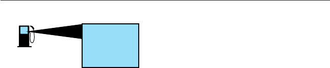
Octane Recommendations - Gasoline Engines
Regular unleaded gasoline with a
pump (R+M)/2 octane rating of 87 is
recommended. Some stations offer
fuels posted as Regular with an
octane rating below 87, particularly in
high altitude areas. Do not use fuels with a posted octane rating below 87.
Do not be concerned if your engine sometimes knocks lightly. However, if
it knocks heavily under most driving conditions while you are using fuel
with the recommended octane rating, see your authorized dealer to
prevent any engine damage.
RUNNING OUT OF FUEL
Gasoline Engine
Avoid running out of fuel because this situation may have an adverse
effect on powertrain components.
If you have run out of fuel:
•You may need to cycle the ignition from off to on several times after
refueling to allow the fuel system to pump the fuel from the tank to
the engine. On restarting, cranking time takes a few seconds longer
than normal.
•If your vehicle is equipped with dual fuel tanks, adding
four–five gallons (15–19 liters) of fuel is enough to restart the
engine. If the vehicle is out of fuel and on a steep grade, more than
four–five gallons (15–19 liters) may be required.
•The service engine soon indicator may come on. For more
information on the service engine soon indicator, see the Instrument
Cluster chapter.
See General information in the Information Displays chapter for
information on Miles to Empty.
Diesel Engine
Avoid running out of fuel as this allows air to enter the fuel system,
which makes restarting the vehicle difficult.
If you have run out of fuel:
•If your vehicle is equipped with dual fuel tanks, adding
four–five gallons (15–19 liters) of fuel is enough to restart the
engine. If the vehicle is out of fuel and on a steep grade, more than
four–five gallons (15–19 liters) may be required.
87
(R+M)/2 METHOD
116 Fuel and Refueling
2013 F-650/750 (f67)
Owners Guide gf, 2nd Printing, March 2013
USA (fus)

•The fuel system must be primed before attempting to restart the
engine. See your engine operator’s manual for instructions on priming
the engine.
•Use caution not to overheat and damage the starter by cranking the
engine for an excessive period of time. You may need to crank the
engine for a longer time than normal. If the engine fails to start in
30 seconds, turn the ignition to the off position and wait for
two minutes before cranking the engine again.
•Any remaining trapped air self-purges from the fuel system once the
engine starts running.
•The engine may run rough and produce white smoke while air is in
the fuel system. This is normal and should stop after a short period of
time.
See General information in the Information Displays chapter for
information on Miles to Empty.
REFUELING
WARNING: Fuel vapor burns violently and a fuel fire can cause
severe injuries. To help avoid injuries to you and others:
•Read and follow all the instructions on the pump island.
•Turn off your engine when you are refueling.
•Do not smoke if you are near fuel or refueling your vehicle.
•Keep sparks, flames and smoking materials away from fuel.
•Stay outside your vehicle and do not leave the fuel pump unattended
when refueling your vehicle - this is against the law in some places.
•Keep children away from the fuel pump; never let children pump
fuel.
•Do not use personal electronic devices while refueling.
Use the following guidelines to avoid electrostatic charge build-up when
filling an ungrounded fuel container:
•Place approved fuel container on the ground.
•DO NOT fill a fuel container while it is in the vehicle (including the
cargo area).
•Keep the fuel pump nozzle in contact with the fuel container while
filling.
•DO NOT use a device that would hold the fuel pump handle in the fill
position.
Fuel and Refueling 117
2013 F-650/750 (f67)
Owners Guide gf, 2nd Printing, March 2013
USA (fus)

Fuel Filler Cap
WARNING: The fuel system may be under pressure. If the fuel
filler cap is venting vapor or if you hear a hissing sound, wait
until it stops before completely removing the fuel filler cap. Otherwise,
fuel may spray out and injure you or others.
WARNING: If you do not use the proper fuel filler cap, excessive
pressure or vacuum in the fuel tank may damage the fuel system
or cause the fuel cap to disengage in a crash, which may result in
possible personal injury.
Note: If you must replace the fuel filler cap, replace it with a fuel filler
cap that is designed for your vehicle. The customer warranty may be
void for any damage to the fuel tank or fuel system if the correct
genuine Ford, Motorcraft® or other certified fuel filler cap is not used.
Your fuel tank filler cap has an indexed design with a
1
⁄
4
–turn on and off
feature. When fueling your vehicle:
1. Turn the engine off.
2. Carefully turn the filler cap counterclockwise until it spins off.
3. Pull to remove the cap from the fuel filler pipe.
4. To install the cap, align the tabs on the cap with the notches on the
filler pipe.
5. Turn the filler cap clockwise a
1
⁄
4
–turn until it clicks at least once.
If the check fuel cap light appears in the instrument cluster and stays on
after you start the engine, the fuel filler cap may not be properly
installed.
If the fuel cap light remains on, at the next opportunity, safely pull off of
the road, remove the fuel filler cap, align the cap properly and reinstall
it. The check fuel cap light may not reset immediately; it may take
several driving cycles for the indicators to turn off. A driving cycle
consists of an engine start-up (after four or more hours with the engine
off) followed by normal city and highway driving.
FUEL CONSUMPTION
Filling the Tank
The advertised capacity is the indicated capacity and the empty reserve
combined. Indicated capacity is the difference in the amount of fuel in a
full tank and a tank when the fuel gauge indicates empty. Empty reserve
is the amount of fuel in the tank after the fuel gauge indicates empty.
118 Fuel and Refueling
2013 F-650/750 (f67)
Owners Guide gf, 2nd Printing, March 2013
USA (fus)

Note: The amount of usable fuel in the empty reserve varies and should
not be relied upon to increase driving range. When refueling your vehicle
after the fuel gauge indicates empty, you might not be able to refuel the
full amount of the advertised capacity of the fuel tank due to the empty
reserve still present in the tank.
For consistent results when filling the fuel tank:
•Turn the ignition off before fueling. An inaccurate reading results if
the engine is left running.
•Use the same fill rate (low–medium–high) each time the tank is filled.
•Allow no more than two automatic click–offs when filling.
•Have the vehicle loading and distribution the same every time.
•When refueling a vehicle equipped with dual fuel tanks, if the two
tanks are not filled equally, the fuel gauge reading may fluctuate
slightly until the fuel level between the two tanks balances out and
becomes equal.
Note: For vehicles equipped with dual fuel tanks, engine performance
may degrade if fuel is not added to both tanks when refueling.
Results are most accurate when the filling method is consistent.
Calculating Fuel Economy
Do not measure fuel economy during the first 1000 miles
(1600 kilometers) of driving (this is your engine’s break-in period); a
more accurate measurement is obtained after 2000–3000 miles
(3200–4800 kilometers). Also, fuel expense, frequency of fill-ups or fuel
gauge readings are not accurate ways to measure fuel economy.
1. Fill the fuel tank completely and record the initial odometer reading.
2. Each time you fill the tank, record the amount of fuel added.
3. After at least three to five tank fill-ups, fill the fuel tank and record
the current odometer reading.
4. Subtract your initial odometer reading from the current odometer
reading.
5. Calculate fuel economy as follows:
•Standard: Divide miles traveled by gallons used.
•Metric: Multiply liters used by 100, then divide by kilometers
traveled.
Keep a record for at least one month and record the type of driving (city
or highway). This provides an accurate estimate of the vehicle’s fuel
economy under current driving conditions. Additionally, keeping records
during summer and winter shows how temperature impacts fuel
economy. In general, lower temperatures mean lower fuel economy.
Fuel and Refueling 119
2013 F-650/750 (f67)
Owners Guide gf, 2nd Printing, March 2013
USA (fus)

SELECTIVE CATALYTIC REDUCTION (SCR) SYSTEM (DIESEL
ENGINE ONLY)
Your vehicle is equipped with a selective catalytic reduction (SCR)
system to help reduce emission levels of oxides of nitrogen from the
exhaust of the diesel engine. The system automatically injects diesel
exhaust fluid (DEF) into the exhaust system to enable proper SCR
function.
Importance of Maintaining the DEF Level
In order for the SCR system to operate properly, the DEF level must be
maintained. Generally, the DEF tank should be filled before the DEF
gauge in the instrument cluster reaches the first low level warning
(see Warning messages and vehicle operations).
The engine control unit monitors the amount of fluid available in the
DEF tank. Failure to maintain an adequate amount of DEF in the system
generates warning messages that appear in the information display and,
unless the DEF tank is refilled, leads to a forced reduction of engine
operations.
Warning Messages and Vehicle Operations
The instrument cluster contains a DEF gauge and indicator lights to alert
you to any low DEF level conditions. The indicator lights illuminate if the
DEF gauge level drops below 0.5 gallons (1.9 liters) in the 5 gallon
(19.0 liters) DEF tank or 1 gallon (3.8 liters) in the 9 gallon (34.0 liters)
DEF tank.
Upon filling the DEF tank after a low level warning, normal operation
resumes when the vehicle is restarted.
120 Fuel and Refueling
2013 F-650/750 (f67)
Owners Guide gf, 2nd Printing, March 2013
USA (fus)
Continued driving without refilling results in the following actions as
required by the U.S. Environmental Protection Agency (EPA):
Low DEF Level Warning Indications and Vehicle Consequences
DEF Tank Level Indicator
Lamps Consequence Remedy
Above initial
warning threshold
(Over 20% full).
None. None. None.
Initial warning
threshold (20% full). DEF solid None.
Add 1 gallon
(3.8L) DEF to
5 gallon (19.0L)
tank or 2 gallons
(7.6L) DEF to
10 gallon
(34.0L) tank.
Critical warning
threshold (15% full).
DEF
blinking None.
First vehicle
consequence (12.5%
full).
DEF
blinking /
Amber engine
solid
25% torque
reduction.
Second vehicle
consequence
(Empty). System
cannot maintain
DEF pressure.
DEF
blinking /
Amber engine
solid
Torque
reduction
increases
from 25% to
40% at rate of
1% each
minute.
Final vehicle
consequence
(Empty) and engine
intentionally shut
down (key off), in
extended idle for
one hour or fuel
tank refilled.
DEF
blinking /
Amber engine
solid /
Red engine
solid
•40% torque
reduction
•5 mph
(8 km/h)
vehicle speed
limit
•1000 RPM
engine speed
limit.
Add 1 gallon
(3.8L) DEF to
5 gallon (19.0L)
tank or 2 gallons
(7.6L) DEF to
10 gallon
(34.0L) tank.
Allow the
system to prime.
Fuel and Refueling 121
2013 F-650/750 (f67)
Owners Guide gf, 2nd Printing, March 2013
USA (fus)
Low DEF Level Warning Indications and Vehicle Consequences
for Emergency Vehicles
DEF Tank Level Indicator
Lamps Consequence Remedy
Above initial
warning threshold
(Over 25% full).
None. None. None.
Below initial warning
threshold (25% full). DEF solid None. Add 1 gallon
(3.8L) DEF to
5 gallon (19.0L)
tank or 2 gallons
(7.6L) DEF to
10 gallon
(34.0L) tank.
Critical warning
threshold (20% full).
DEF
blinking None.
First vehicle
consequence (15%
full).
DEF
blinking /
Amber engine
solid
Vehicle speed
limited to
55 mph
(88 km/h).
*
Final vehicle
consequence
(Empty) and engine
intentionally shut
down (key off) or in
extended idle for
one hour.
DEF
blinking /
Amber engine
solid /
Red engine
solid
Vehicle speed
limited to
25 mph
(40 km/h).
**
Add 1 gallon
(3.8L) DEF to
5 gallon (19.0L)
tank or 2 gallons
(7.6L) DEF to
10 gallon
(34.0L) tank.
Allow the
system to prime.
*
The vehicle speed restriction is suspended during pump operation when
using any of the following engine control modes:
•Power take-off
•Remote power take-off
•Remote throttle
•SAE J1939–commanded pressure governor.
**
Those installations using a transmission tailshaft-driven power take-off
or pump during a stationary operation are also limited to 25 mph
(40 km/h) equivalent tailshaft speed during a final vehicle consequence.
122 Fuel and Refueling
2013 F-650/750 (f67)
Owners Guide gf, 2nd Printing, March 2013
USA (fus)
Incorrect DEF Quality Warning Indications and Vehicle
Consequences
Condition Indicator
Lamps Consequence Remedy
Correct DEF quality. None. None. None.
Initial warning when
incorrect DEF
quality is detected.
Amber engine
solid None.
Replace DEF
with
Ford-approved
Initial warning one
hour after incorrect
DEF quality is
detected.
Amber engine
solid
25% torque
reduction.
Initial warning three
hours after incorrect
DEF quality is
detected.
Amber engine
solid
Torque
reduction
increases
from 25% to
40% at rate of
1% each
minute.
Final vehicle
consequence three
hours after incorrect
DEF quality is
detected and engine
intentionally shut
down (key off), in
extended idle for
one hour or fuel
tank refilled.
*
Amber engine
solid /
Red engine
solid
•25% torque
reduction
•5 mph
(8 km/h)
vehicle speed
limit
•1000 RPM
engine speed
limit.
**
*
Refueling the fuel tank is defined as increasing the fuel volume level by
15%.
**
Final consequence for vehicles equipped with a manual transmission is
1000 RPM. Final consequence for vehicles equipped with an automatic
transmission is 1100 RPM.
Fuel and Refueling 123
2013 F-650/750 (f67)
Owners Guide gf, 2nd Printing, March 2013
USA (fus)
Incorrect DEF Quality Warning Indications and Vehicle
Consequences for Emergency Vehicles
Condition Indicator
Lamps Consequence Remedy
Correct DEF quality. None. None. None.
Initial warning when
incorrect DEF
quality is detected.
Amber engine
solid None.
Replace DEF
with
Ford-approved
DEF.
Initial warning
10 hours after
incorrect DEF
quality is detected.
Amber engine
solid
Vehicle speed
limited to
55 mph
(88 km/h).
*
Final vehicle
consequence
20 hours after
incorrect DEF
quality is detected
and engine
intentionally shut
down (key off), in
extended idle for
one hour or fuel
tank refilled.
*
Amber engine
solid /
Red engine
solid
Vehicle speed
limited to
25 mph
(40 km/h).
*
The vehicle speed restriction is suspended during pump operation when
using any of the following engine control modes:
•Power take-off
•Remote power take-off
•Remote throttle
•SAE J1939–commanded pressure governor.
124 Fuel and Refueling
2013 F-650/750 (f67)
Owners Guide gf, 2nd Printing, March 2013
USA (fus)
SCR Faults and Vehicle Consequences
Condition Indicator
Lamps Consequence Remedy
No faults. None. None. None.
Initial warning when
fault is detected.
Amber engine
solid None.
Correct and
clear fault
condition.
Initial warning one
hour after fault is
detected.
Amber engine
solid
25% torque
reduction.
Secondary warning
five hours after fault
is detected.
Amber engine
solid
Torque
reduction
increases
from 25% to
40% at rate of
1% each
minute.
Final vehicle
consequence five
hours after fault is
detected and engine
intentionally shut
down (key off), in
extended idle for
one hour or fuel
tank refilled.
*
Amber engine
solid /
Red engine
solid
•40% torque
reduction
•5 mph
(8 km/h)
vehicle speed
limit
•1000 RPM
engine speed
limit.
**
*
Refueling the fuel tank is defined as increasing the fuel volume level by
15%.
**
Final consequence for vehicles equipped with a manual transmission is
1000 RPM. Final consequence for vehicles equipped with an automatic
transmission is 1100 RPM.
Fuel and Refueling 125
2013 F-650/750 (f67)
Owners Guide gf, 2nd Printing, March 2013
USA (fus)
SCR Faults and Vehicle Consequences for Emergency Vehicle
Condition Indicator
Lamps Consequence Remedy
No faults. None. None. None.
Initial warning when
fault is detected.
Amber engine
solid None.
Correct and
clear fault
condition.
Initial warning
10 hours after fault
is detected.
Amber engine
solid
Vehicle speed
limited to
55 mph
(88 km/h).
*
Final vehicle
consequence at
40 hours after fault
is detected and
engine intentionally
shut down (key off)
or in extended idle
for one hour.
Amber engine
solid /
Red engine
solid
Vehicle speed
limited to
25 mph
(40 km/h).
*
The vehicle speed restriction is suspended during pump operation when
using any of the following engine control modes:
•Power take-off
•Remote power take-off
•Remote throttle
•SAE J1939–commanded pressure governor.
Filling the DEF Tank
WARNING: Make sure that DEF does not come into contact
with eyes, skin or clothing. Should DEF contact your eyes, flush
them with plenty of water and contact a physician. Clean affected skin
with soap and water. If DEF is swallowed, drink plenty of water and
contact a physician immediately.
WARNING: Refill DEF in a well-ventilated area. When opening
the cap on the DEF tank or bottle containing DEF, ammonia
vapors may escape. The vapors can be irritating to skin, eyes and
mucous membranes. Inhaling ammonia vapors can cause burning to the
eyes, throat and nose and cause coughing and watery eyes.
126 Fuel and Refueling
2013 F-650/750 (f67)
Owners Guide gf, 2nd Printing, March 2013
USA (fus)

Note: Do not put DEF in the fuel tank or any other tank on the vehicle.
This can cause damage to components not covered by your vehicle’s
warranty.
Your vehicle is equipped with a DEF tank with a blue-capped filler port.
The 5 gallon (19.0L) DEF tank is located on the left side of the vehicle
under the cab. The 9 gallon (34.0L) DEF tank is located on the right
side of the vehicle behind the cab (Regular Cab and Super Cab) or under
the cab (Crew Cab). The tank can be filled using a nozzle at a DEF
filling station (similar to fuel fill) or using a DEF bottle with a spout.
Motorcraft® brand DEF bottles are recommended. Other aftermarket
bottles can be used but should have a seal on the spout and an internal
vent tube to achieve best fill performance and prevent overfilling.
You can purchase DEF at your authorized dealer, most highway truck stops
or you can contact roadside assistance for help in finding a retailer that
sells DEF. See the Customer Assistance chapter for more information.
Also, a government website locator is available for diesel exhaust fluid
supplies. The following web address can be used to find the nearest
location to purchase DEF: http://www.afdc.energy.gov/afdc/locator/def.
Use Motorcraft® DEF or equivalent meeting Ford
specification WSS-M2C130-A and/or ISO 22241. Use
only DEF certified by the American Petroleum
Institute. Look for this certification trademark. Repairs
resulting from the use of non-certified DEF products
may not be covered by your vehicle’s warranty.
Maintaining the purity of DEF is important to avoid malfunctions in the
SCR system.
If DEF is removed from the tank for any reason (such as repair work),
the same DEF must not be used to refill the tank as its purity is no
longer guaranteed.
To fill the DEF tank, see your authorized dealer or do the following
(before filling the DEF tank in cold climates, see Filling the DEF tank
in cold climates later in this section):
DEF Bottle Fill with Spout
The following procedure applies to Motorcraft® DEF or similar DEF
bottles. For other brands or bottle types, see the instructions on the
bottle label.
Fuel and Refueling 127
2013 F-650/750 (f67)
Owners Guide gf, 2nd Printing, March 2013
USA (fus)
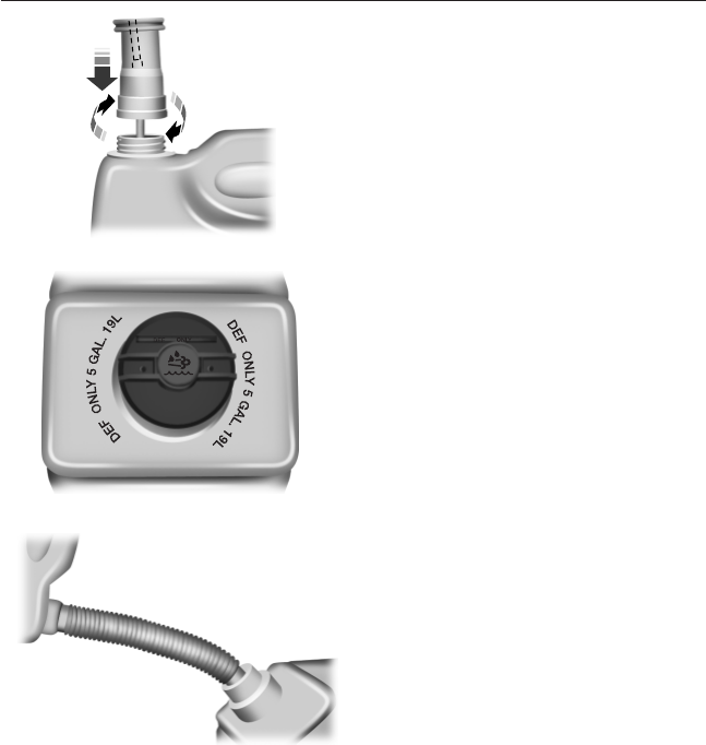
1. Remove the cap from the DEF
container and twist the spout onto
the container until the locking tab is
engaged.
2. Open the DEF filler port on the
vehicle by turning the blue cap
counterclockwise a
1
⁄
4
-turn.
3. Lift and hold the DEF container,
without tipping, and insert the
spout, into the DEF filler port.
4. Lift and tip the container to let
DEF flow into the tank. Pour DEF
until the container is empty or DEF
flow stops. DEF can be seen flowing
through the spout, but does not
completely fill the spout while
flowing. Air is trapped in the spout
while DEF is flowing. When the
DEF tank is full, DEF completely
fills the spout and displaces the air
in the spout.
5. Once the spout is full with DEF (no more large air pockets), return
the container to the vertical position slightly below the DEF filler port
and let any DEF drain out of the spout. DO NOT try to continue to add
DEF to the tank by shaking or repositioning the container to induce flow.
This may cause spilling and overfill the tank. Overfilling the DEF tank
can cause damage to the tank.
6. Once the spout has drained, remove the spout from the DEF filler
port and install the blue cap on the DEF filler port by turning the cap
clockwise a
1
⁄
4
-turn.
128 Fuel and Refueling
2013 F-650/750 (f67)
Owners Guide gf, 2nd Printing, March 2013
USA (fus)

7. Remove the spout from the DEF container and install the cap back on
the bottle.
8. If the container is empty, discard the empty container and spout, or
recycle if possible. If there is some DEF left in the container, retain it
and the spout for later use. Store the spout to make sure it is kept clean.
9. Wipe away any DEF that has spilled on painted surfaces with water
and a damp cloth.
DEF Filling Station Nozzle Fill
Filling the DEF tank using a nozzle is similar to a normal fuel fill. The
nozzle shuts off automatically when the tank is full. Do not continue to
fill the tank as this may cause spillage and overfill the tank, which can
cause damage.
Filling the DEF Tank in Cold Climates
DEF freezes below 12°F (-11°C). If temperatures are at or below 12°F
(-11°C) for an extended period of time, and the DEF tank is full, and
you are not going to drive the vehicle, there is a risk that the tank could
freeze, causing damage. If low temperature conditions are expected, you
should keep your tank at least 50% full and make sure you add DEF on
level ground to prevent the fluid from freezing on an angle.
Contaminated DEF
SCR systems are sensitive to contamination of the DEF. USE ONLY
CERTIFIED DIESEL EXHAUST FLUID. If the system becomes
contaminated and the vehicle continues to be driven with contaminated
DEF, the following warnings result:
Reducing Agent and Vehicle Consequence
Condition Indicator Lamps Consequence
Correct reducing agent None None
Incorrect reducing agent, at
detection
Amber engine None
Incorrect reducing agent, at
detection + 10 hours
Amber engine 40% torque
reduction
Incorrect reducing agent, at
detection + 20 hours and
engine intentionally shut
down or in extended idle
Amber engine
Red engine
40% torque
reduction+5mph
(8 km/h) vehicle
speed limit
Fuel and Refueling 129
2013 F-650/750 (f67)
Owners Guide gf, 2nd Printing, March 2013
USA (fus)

If any of these warnings appear, the contaminated DEF must be purged
and replaced with approved DEF. See an authorized dealer or the
Workshop Manual.
Upon filling the DEF tank after a DEF contaminated warning, normal
operation resumes when the vehicle is restarted.
DEF Guidelines and Information
•DEF is non-flammable, non-toxic, colorless and water-soluble.
•Use only DEF that carries the trademark: AMERICAN PETROLEUM
INSTITUTE CERTIFIED DIESEL EXHAUST FLUID.
•An ammonia odor may be smelled when the cap is removed or during
a refill. Refill the DEF tank in a well-ventilated area.
•Prior to filling the tank, make sure the surrounding area is clean of
debris to prevent contamination.
•Do not dilute DEF with water or any other liquid.
•Do not put DEF in the fuel tank or any other tank on the vehicle.
•Do not re-use the nozzle or the DEF container once it is emptied.
•Do not overfill the DEF tank.
•Avoid spilling DEF on painted surfaces, carpeting or plastic
components. Immediately wipe away any DEF that has spilled on
painted surfaces with a damp cloth and water. If it has already
crystallized, use warm water and a sponge.
•DEF freezes below 12°F (-11°C). Your vehicle is equipped with an
automatic pre-heating system which allows the DEF system to
operate below 12°F (-11°C).
•Do not store the DEF bottle in your vehicle. If it leaks, it could cause
damage to interior components or release an ammonia odor inside the
vehicle.
•Store DEF out of direct sunlight and in temperatures between
23°F–68°F (-5°C–20°C).
NOISE EMISSIONS
In order to comply with the federal exterior noise regulations, your
vehicle may be equipped with noise emission items. Depending on the
vehicle configuration, it may have all or some of the following items:
Air Intake System: Inspect the air cleaner. Do not alter its location. Do
not alter inlet and outlet piping.
Body: Inspect wheel well splash shields, cab shields and underhood
insulation for deterioration, dislocation and orientation.
130 Fuel and Refueling
2013 F-650/750 (f67)
Owners Guide gf, 2nd Printing, March 2013
USA (fus)

Cooling System:
•Inspect the fan for blade damage. If damage is found, replace with
the recommended parts. Inspect for fan-to-shroud interference and
any damage to shroud, such as cracks and holes.
•Do not change fan ratio or alter fan spacer dimensions and positions.
•Inspect fan clutch for proper operation. Make sure the fan is
disengaged when cooling of the engine is not required.
•Inspect radiator shutters (if equipped) for proper operation. The
shutters should be open during normal operating temperatures.
Engine: Valve covers and block covers are made to damp-out engine
mechanical noise and, if needed, should be replaced with recommended
parts. Check for mechanical isolations.
Transmission Enclosure: Inspect for cracks, holes and tears. Clean any
deposits, such as oil, dirt and stones.
Exhaust System:
•Inspect for leaks at various joint connections and loose clamps.
•Perform a visual inspection for cracks or holes in the muffler and tail
pipe.
•Always use the recommended parts when items need to be replaced.
•Do not change the tail pipe elbow or offset tail pipe orientation from
the standard position as originally received.
•To avoid abnormal changes in vehicle sound levels, it is necessary for
the owner to perform inspections and necessary maintenance at the
intervals shown in the Scheduled Maintenance chapter.
Fuel and Refueling 131
2013 F-650/750 (f67)
Owners Guide gf, 2nd Printing, March 2013
USA (fus)

MANUAL TRANSMISSION OPERATION (IF EQUIPPED)
Manual transmission shift patterns are displayed on either the shift lever
knob or the sun visor. Study this information carefully before you drive
the vehicle even though you may be familiar with similar units. Do not
attempt to drive the vehicle without knowing the exact shift pattern of
the transmission. Consult your authorized dealer if any questions exist as
to the shifting instructions posted in your vehicle.
Driving Hints
WARNING: Do not coast the vehicle with the clutch pedal
pressed or with the transmission in neutral. This practice could
result in loss of vehicle control.
The following driving hints are provided as a brief, general guide in
operating the different manual transmissions used in your vehicle.
•When shifting into first gear or reverse with your vehicle standing
still, quickly release and press the clutch pedal (if necessary to
complete gear engagement).
•Always use the lowest (or most appropriate) gear to start the vehicle.
•Always use a gear ratio low enough to allow the engine to operate
above the minimum engine operation speed range.
•Do not lug the engine.
•Do not slam or jerk the gearshift lever into gear.
•When more power is required, shift to a lower gear and accelerate
the engine near the governed speed.
To go forward, press the clutch pedal in and shift into first gear while
the engine is idling. Engage the clutch while pressing the accelerator to
start forward. Operate the clutch and upshift as required by driving
conditions.
To go backward, put the gearshift lever in reverse and engaging the
clutch while pressing lightly on the accelerator.
Shifting with a Synchronized Transmission
With the clutch pedal pressed in, use the second gear synchronizer to
stop the clutch disc rotation; this allows smooth engagement of first gear
or reverse. To complete the gear engagement, it may be necessary to
apply light pressure to the gearshift lever during initial engagement of
the clutch. It takes a second or two to match gear speeds; steady
pressure on the gearshift lever helps the synchronizer perform its job
more quickly. If the gearshift lever is forced into position, this action
defeats the purpose of the synchronizer by causing gear clash.
132 Transmission
2013 F-650/750 (f67)
Owners Guide gf, 2nd Printing, March 2013
USA (fus)

Shifting with a Non-Synchronized Transmission
See Clutch brake and Double clutch procedures in the Clutch section
of this chapter.
Clutch
Do not ride or slip the clutch as this causes unnecessary heat and wear.
Maintain the specified clutch adjustment to prolong its life and regularly
inspect the clutch control linkage for tightness. See the Scheduled
Maintenance chapter for other maintenance information. When
adjustment of the clutch is necessary, it is very important that the work
be performed properly or early clutch failure may result and a costly
clutch overhaul may become necessary. Clutch work should only be
performed by a qualified technician.
Note: Continued use of a damaged or worn clutch, prolonged clutch
slippage or downshifting at excessive speeds can result in a failure of the
engine, transmission or clutch components.
Note: To avoid premature clutch wear and failure, do not drive with
your foot resting on the clutch pedal or use it to hold the vehicle at a
standstill on an upgrade as when waiting for a traffic light.
Engaging the Clutch
•Always start in the proper gear. An empty vehicle can start in a
higher gear than a fully-loaded vehicle. Starting in too high a gear can
cause clutch slippage and excessive heat and wear on the clutch. A
gear that starts the vehicle moving at idle speed is the correct gear. If
the engine has to be revved to get the vehicle going, the gear
selection is too high.
•Do not shift until the vehicle has reached the proper speed.
Upshifting before the vehicle has reached the proper speed can cause
clutch slippage and excessive heat and wear on the clutch.
•Never hold a vehicle on a grade with the clutch. This causes the
clutch to slip and can actually burn up the clutch.
•Never coast with the clutch disengaged. The high RPM
(sometimes over 10000) can actually burst the facing material of the
clutch.
•Never engage the clutch while coasting. Re-engaging the clutch
after coasting may not only cause a great shock to the clutch, but the
whole drivetrain. Internal engine damage or clutch and flywheel
failure can result from this.
Transmission 133
2013 F-650/750 (f67)
Owners Guide gf, 2nd Printing, March 2013
USA (fus)

If the transmission is equipped with a ceramic clutch, you must start the
vehicle moving in first gear and engage the clutch before pressing the
accelerator at idle. Also, do not try to slip the clutch by raising engine
RPM and riding or feathering the clutch pedal since this causes erratic
engagement which can cause engine stalling and potential serious
damage to driveline components.
Clutch Brake (Non-Synchronized Transmissions) - Vehicle
Stationary
A clutch brake is used to stop transmission input shaft rotation so that
the initial first gear or reverse gear selection can be accomplished when
the vehicle is stationary and the engine is at idle speed. Clutch brake
application occurs in the last inch (25 millimeters) of clutch pedal travel.
When using the clutch brake, fully press the clutch pedal and shift the
transmission into first gear or reverse. If the transmission won’t go into
one of these gears, slowly release the clutch pedal while applying light
pressure on the transmission shift lever until it shifts into gear.
Note: After engagement of first gear, do not use the clutch brake for
upshifting or downshifting. If you do, clutch brake life shortens and gear
selection shift efforts may increase.
Double-Clutch Procedures - Non-Synchronized Transmissions
In order to properly upshift or downshift:
1. Press the clutch pedal to disengage the clutch.
2. Shift the transmission into neutral.
3. Release the clutch pedal.
If upshifting, wait until the engine speed matches the transmission
speed of the gear you are selecting.
If downshifting, accelerate the engine until the engine speed matches
the input speed of the gear you are selecting. Press the clutch pedal
immediately and shift into the desired gear, then release the clutch
pedal.
134 Transmission
2013 F-650/750 (f67)
Owners Guide gf, 2nd Printing, March 2013
USA (fus)
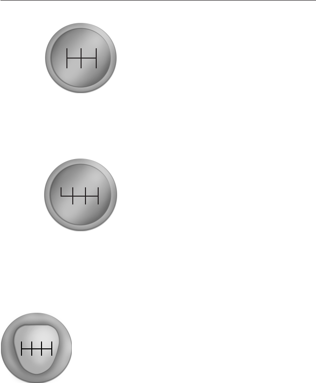
Eaton FS-5205A 5–speed
This transmission is equipped with
five forward gears and one reverse;
gears 2–5 are synchronized. The
shift pattern is embossed on the
gear shift knob.
Do not shift the transmission into reverse while the vehicle is moving as
this could damage the transmission.
Eaton FS–5406A, FS–5406N, FS–6406A and FSO–6406A 6-speed
These transmissions are equipped
with six forward gears and one
reverse; all forward gears are
synchronized. The shift pattern is
embossed on the gear shift knob.
Do not shift the transmission into
first gear or reverse while the
vehicle is moving as this could
damage the transmission.
Spicer ES56-7B and ES066-7B 7-speed
These transmissions are equipped with seven forward
gears and one reverse; gears 2–7 are synchronized. The
shift pattern is embossed on the gear shift knob.
Do not shift the transmission into first gear or reverse while the vehicle
is moving as this could damage the transmission.
R24
531
R13
46
5
2
R24
57
6
31
Transmission 135
2013 F-650/750 (f67)
Owners Guide gf, 2nd Printing, March 2013
USA (fus)
AUTOMATIC TRANSMISSION OPERATION (IF EQUIPPED)
WARNING: Hold the brake pedal down while you move the
gearshift lever between positions. If you do not hold the brake
pedal down, your vehicle may move unexpectedly and cause property
damage, personal injury or death.
Main transmission, auxiliary transmission, transfer case and power
take-off (PTO) control shift patterns can be found on a placard or decal
on the driver’s sun visor, on the instrument panel or on the shift control
itself.
The main transmission control is used to select the various gear ratios or
speeds of the transmission. Selecting position Ddoes not change the
transmission gear ratio, but is used where the gear ratios in the main
transmission are adequate to handle the vehicle operation.
If the transmission fails to shift properly, check the inline 10A fuse
located in the battery cables above the battery.
Brake-shift Interlock
Vehicles equipped with a gasoline engine have a brake-shift interlock
feature that prevents the gearshift lever from being moved from position
Pwhen the ignition is in the on position and the brake pedal is not
pressed.
If you cannot move the gearshift lever out of position Pwith the ignition
in the on position and the brake pedal pressed, it is possible that a fuse
has blown or the vehicle’s brake lamps are not operating properly. See
the Fuses chapter.
WARNING: Do not drive your vehicle until you verify that the
brake lamps are working.
WARNING: When doing this procedure, you will be taking the
vehicle out of park which means the vehicle can roll freely. To
avoid unwanted vehicle movement, always fully set the parking brake
prior to doing this procedure. Use wheel chocks if appropriate.
136 Transmission
2013 F-650/750 (f67)
Owners Guide gf, 2nd Printing, March 2013
USA (fus)
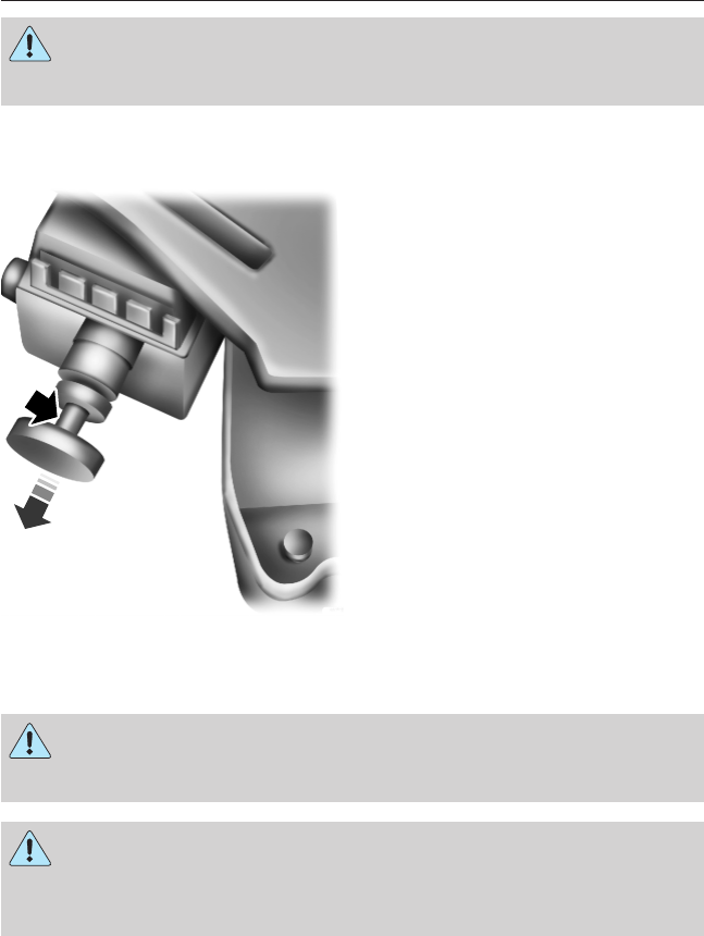
WARNING: If the parking brake is fully released, but the brake
warning lamp remains illuminated, the brakes may not be
working properly. See your authorized dealer.
If the fuse is not blown and the brake lamps are working properly, the
following procedure allows you to move the gearshift lever from position P:
1. Apply the parking brake, and
turn the engine off.
2. Remove the lower finish panel
below the steering column.
3. Turn the key to the on position,
but do not start the engine.
4. Pull back on the solenoid, and
at the same time, shift the
transmission into position N.
5. Start the vehicle.
See your authorized dealer as
soon as possible if this
procedure is used.
Six–speed TorqShift® Transmission
WARNING: Always set the parking brake fully and make sure
the gearshift is latched in position P. Turn the ignition to the off
position and remove the key whenever you leave your vehicle.
WARNING: Do not use the tow/haul feature when driving in icy
or slippery conditions as the increased engine braking can cause
the rear wheels to slide and the vehicle to swing around with the
possible loss of vehicle control.
Transmission 137
2013 F-650/750 (f67)
Owners Guide gf, 2nd Printing, March 2013
USA (fus)

Position P
This position locks the transmission and prevents the rear wheels from
turning.
To put your vehicle in gear:
1. Start the engine.
2. Press the brake pedal.
3. Move the gearshift lever into the desired gear.
To put your vehicle in position P:
1. Come to a complete stop.
2. Move the gearshift lever and securely latch it in position P.
Position R
With the gearshift lever in position R, the vehicle moves backward. Always
come to a complete stop before shifting into and out of position R.
Position N
With the gearshift lever in position N, the vehicle can be started and is
free to roll. Hold the brake pedal down while in this position.
Position D
This is the normal driving position for the best fuel economy. This
position allows automatic upshifts and downshifts in gears one through
six.
Position 4
This position allows automatic upshifts and downshifts in gears one
through four.
Position 2
Use position 2to start-up on slippery roads or to provide additional
engine braking on downgrades.
PRND4 2 1
138 Transmission
2013 F-650/750 (f67)
Owners Guide gf, 2nd Printing, March 2013
USA (fus)

Position 1
•Provides maximum engine braking.
•Allows upshifts by moving gearshift lever.
•The transmission does not downshift into position 1at high speeds; it
downshifts to a lower gear and then shifts into position 1when the
vehicle reaches slower speeds.
Forced Downshifts
•Allowed in position D.
•Press the accelerator to the floor.
•Allows transmission to select an appropriate gear.
Allison 2200 with Parking Pawl Feature
Note: Also see the separate Allison Transmission Operator’s Manual.
WARNING: Always set the parking brake fully. Do not use the
gearshift in place of the parking brake.
WARNING: To avoid sudden, unexpected vehicle movement
and possible personal injury or death:
1. Bring the vehicle to a complete stop.
2. Shift the transmission into position P. Slowly lift your foot from the
brake pedal to engage the transmission parking pawl mechanism.
3. Apply the parking brake and make sure it is holding properly. Do not
rely solely on the parking mechanism of the transmission.
4. Turn the engine off when you leave the vehicle. Never leave the
vehicle unattended when the engine is running.
A parking pawl effectively grounds the transmission’s output shaft
preventing rotation of the driveline. If the vehicle is stationary, selecting
position Pplaces the transmission in neutral and engages the parking
pawl. Always use the parking brake when parking the vehicle.
Note: If position Pis selected when the vehicle is in motion, the parking
pawl mechanism ratchets and DOES NOT hold the truck.
Transmission 139
2013 F-650/750 (f67)
Owners Guide gf, 2nd Printing, March 2013
USA (fus)

Allison 2500
WARNING: To avoid sudden, unexpected vehicle movement
and possible personal injury or death:
1. Bring the vehicle to a complete stop.
2. Shift the transmission into position N.
3. Apply the parking brake and make sure it is holding properly.
4. Turn the engine off when you leave the vehicle. Never leave the
vehicle unattended when the engine is running.
This transmission is available with a column-mounted gearshift lever. The
gear positions are displayed on the RNDL in the instrument cluster.
Allison 3000
Note: For more information regarding this transmission, see the separate
Allison 3000 Series Operator’s Manual.
The Allison 3000 series offers two shift modes: Performance and
Economy.
Performance mode gives the best all-around transmission operation. The
transmission defaults to this mode when you start the engine. Pressing
MODE on the shifter switches to Economy mode and illuminates the
Mode ON lamp.
Economy mode provides operation at lower engine RPM while
maintaining adequate performance.
If the engine speed is above idle when a gear is selected using the
shifter, the vehicle does not move; the shifter must be moved to re-select
a gear after the engine speed returns to idle.
Torque Lock
If your vehicle is parked on an incline and position Pis not properly
engaged (the parking brake is not applied before the transmission is
shifted into position P), the weight of the vehicle may generate an
excessive amount of torque on the parking pawl, making it difficult to
shift the transmission out of position P. Hold the brake pedal down while
shifting out of position P, then release the parking brake.
140 Transmission
2013 F-650/750 (f67)
Owners Guide gf, 2nd Printing, March 2013
USA (fus)
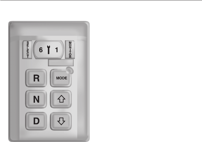
Allison 3000 Series Push-Button Shifter
To shift to Reverse or Drive:
1. Press the brake pedal.
2. Press R or D on the shifter.
3. Release the brake pedal.
To select a higher range when in
Drive, press the up arrow button.
To select a lower range when in
Drive, press the down arrow button.
To place the transmission in Neutral,
press N.
Allison 3000 Prognostics
This transmission is equipped with the Allison Prognostics feature that
can alert the driver to needed transmission maintenance and
transmission fluid and filter life. See the separate Allison transmission
manual for complete details.
POWER TAKE-OFF (PTO) OPERATION (IF EQUIPPED)
A PTO unit allows the transmission to power auxiliary equipment to run
devices such as snowplows, aerial lifts, tow truck lifts, cement mixers or
dump trucks.
Vehicles Equipped with an Allison Automatic Transmission
(Except 3000 Series)
The PTO can be operated while the vehicle is standing or moving.
To engage the PTO, apply the brakes and shift to any gear other than
position N, then engage the PTO.
If engagement is prevented by the gear teeth not meshing properly,
release the brakes and allow the vehicle to creep slightly or shift the
Transmission 141
2013 F-650/750 (f67)
Owners Guide gf, 2nd Printing, March 2013
USA (fus)

selector to position Nand then back into gear. The PTO should never be
engaged by clashing the gear teeth. This may damage the PTO unit and
the transmission PTO drive gear teeth, resulting in further damage to the
transmission and PTO.
PTO Operation with Vehicle Stationary
WARNING: When the PTO is operated with the vehicle
stationary, the transmission must be placed in position Nwith the
parking brake set. If the transmission is not in position Nand is
equipped with a remote throttle control, an increase in engine speed
can overpower the parking brake and cause the vehicle to move,
possibly resulting in personal injury and/or property damage.
Stop the vehicle, idle the engine and set the parking brake. Make sure
the gear selector is in any forward drive range, then engage the PTO.
After the PTO is engaged, move the range selector to position N.
Increase the engine speed until the desired PTO operation speed is
obtained. To disengage the PTO after operation with the vehicle
standing, release the throttle, allow the drive equipment to come to a
stop, and then disengage the PTO.
PTO Operation while Vehicle Is Moving
After the PTO is engaged for driven vehicle operation, shift to the
desired range and drive the vehicle. The speed of the PTO, during this
period of operation, always maintains direct relation to vehicle speed.
PTO speed decreases in relation to vehicle (transmission output) speed
as shifts to a higher gear occur. When operating the PTO while the
vehicle is moving, the PTO may be disengaged whenever it is no longer
required. When there is no load on the PTO gear, it can be pulled out of
engagement.
Vehicles Equipped with an Allison 3000 Series Automatic
Transmission
The PTO drive gear is engine-driven and provides direct engine power.
The PTO can be operated when the vehicle is either stationary or
moving. The PTO gear is in constant mesh with the drive gear in the
torque converter housing. A friction clutch or constant drive is used to
transmit power to the PTO.
Vehicles Equipped with a Manual Transmission
Transmission-mounted PTO units are available for local installation on
your vehicle. See your Body Builder’s Layout Book for restrictions on
use and installation of PTO units.
142 Transmission
2013 F-650/750 (f67)
Owners Guide gf, 2nd Printing, March 2013
USA (fus)

To engage the PTO unit, stop the vehicle and place the transmission in
position N. Press the clutch and allow the gears to stop rotating, then
engage the PTO unit. The PTO can also be selected with the
transmission in gear as long as the clutch is pressed.
When operating the PTO with the vehicle stationary, first set the parking
brake (chock the wheels if the vehicle is on a hill or another uneven
surface).
REAR AXLES
Gross Axle Weight
WARNING: Exceeding these ratings by overloading can cause
component failure resulting in property damage, personal injury
or death.
Your truck has gross axle weight, gross vehicle weight and gross
combination weight ratings. Do not exceed these ratings.
Locking or Limited-Slip Differentials
WARNING: If both wheels are not raised off the ground, the one
wheel that is not raised may pull the vehicle off its support,
possibly resulting in personal injury
If your vehicle is equipped with a locking or limited-slip differential, note
the following:
•Power is transmitted to the opposite wheel should one of the wheels
begin to slip.
•Both wheels must be raised off the ground should it be necessary to
operate one wheel with the vehicle stationary.
Driver-controlled Differential Lock
Note: Never use the differential lock at vehicle speeds above 25 mph
(40 km/h).
Some drive axles have a driver-controlled differential lock. The
differential lock can lock or unlock the differential when the vehicle is
moving or stopped. When extra traction is required, the differential lock
provides full power to both axles.
When the differential is locked, the vehicle’s turning radius increases
(under-steer).
Transmission 143
2013 F-650/750 (f67)
Owners Guide gf, 2nd Printing, March 2013
USA (fus)
The differential can be locked or unlocked when the vehicle is moving at
a constant speed of under 25 mph (40 km/h) and while the wheels are
not slipping. The differential must not be locked when the vehicle is
traveling down steep grades and traction is minimal.
The differential lock and differential lock light automatically disengage at
speeds above 25 mph (40 km/h). The differential lock remains off until
either the vehicle is restarted or the differential lock switch is turned off
then back on.
Turn the engine off and raise all drive wheels of the locker differential
axle in order to prevent the vehicle from moving when servicing the
wheels, tires or brakes. Axles equipped with a NoSPIN Detroit Locker
differential deliver power to both wheels even when only one wheel is on
the ground.
WARNING: Failure to raise all drive wheels with this type of
differential could cause the vehicle to move unexpectedly,
resulting in property damage, personal injury or death.
Care should be taken to avoid sudden accelerations when both drive
wheels are on a slippery surface.
WARNING: Sudden accelerations on slippery surfaces could
cause the wheels to spin, the vehicle to turn sideways on a
crowned road surface or in a turn, possibly resulting in loss of vehicle
control and personal injury.
Fluid Temperature
Axle operating temperatures normally do not exceed 100°F (38°C).
If the operating temperature exceeds 230°F (110°C), the rate of axle
lubrication oxidation increases and shortens the life of the lubricant and
seals, requiring axle lubrication changes to become more frequent to
preserve the axle. Extreme Pressure (EP) lubricants should not be run
consistently above 230°F (110°C).
Axle Conversions
WARNING: When operating a loaded vehicle, the driver must
keep all adjustable axles on the ground at all times, supporting
their share of the vehicle’s load. Failure to do so can overload other
axles, tires, wheels, springs, steering components, brakes and frames,
resulting in early component failure, loss of vehicle control, possible
property damage and personal injury.
144 Transmission
2013 F-650/750 (f67)
Owners Guide gf, 2nd Printing, March 2013
USA (fus)
It is not recommended, or approved, for axle conversions to be
performed. However, it is understood that, on occasion, aftermarket
add-on axles are installed by others on the truck chassis which allow
operator control for weight transfer from other axles (i.e., air lift axles).
TWO-SPEED REAR AXLE (IF EQUIPPED)
WARNING: Never shift a two-speed axle when descending a
steep grade as this may cause loss of vehicle control and result in
personal injury.
Note: Do not shift between ranges when the speed control is on.
A two-speed rear axle allows the
driver to select a low range for
greater pulling power and a high
range for greater road speed and
fuel economy. These ranges can also
be used to provide additional steps
between transmission shifts when
driving on steep grades or fuel
economy may be factors.
Axle Shifting with a Manual Transmission
To downshift, select the next lower gear, release and press the
accelerator pedal rapidly, or while holding the accelerator pedal down,
release and engage the clutch rapidly. Note: The clutch method is
recommended when driving at slower speeds.
To upshift, keep the accelerator pedal down, select the next higher gear,
release the accelerator and pause until the axle upshifts. Note:
De-clutch for smoother axle upshifts when driving at slower speeds.
Axle Shifting with an Automatic Transmission
Note: You cannot split-shift with an automatic transmission. Also,
downshifting above 40 mph (64 km/h) may result in transmission or axle
damage.
Note: Do not shift the axle to LOW with the vehicle in motion.
Use LOW when you drive a fully-loaded vehicle on a severe grade or in
congested traffic. Press the upper portion of the switch.
Use HIGH for all normal driving conditions with a lightly-loaded or
partially-loaded vehicle. Press the lower portion of the switch.
2SPD
LOW
HIGH
Transmission 145
2013 F-650/750 (f67)
Owners Guide gf, 2nd Printing, March 2013
USA (fus)
To shift the axle from LOW to HIGH with the vehicle stopped, place the
transmission in position N, then press the lower part of the switch.
To shift the axle from LOW to HIGH with the vehicle moving, accelerate
to approximately 35 mph (56 km/h), press the lower part of the switch
while the transmission is in position N, then release and apply the
accelerator.
To shift the axle from HIGH to LOW with the vehicle stopped, place the
transmission in position N, then press the upper part of the switch.
Split-shifting (Combined Axle and Transmission Shift)
(Manual Transmission Only)
To downshift the axle to a slower ratio and shift the transmission, shift
the transmission and move the switch to the lower ratio before the
clutch is re-engaged.
To upshift the axle and shift the transmission, move the switch to a
faster ratio and make the transmission shift in the usual manner.
Split-shift Sequence
Ratio combination 1234567891011
Transmission gear 1st 1st
2nd 2nd
3rd 3rd 4th 4th 5th 6th 6th
Axle range LO HI LO HI LO HI LO HI LO LO HI
Ratio Extender Use
Low end: A two-speed axle can be used as a ratio-extender when
split-shifting is not necessary. For low end use, just shift the axle into
LOW to start out, and shift to HIGH when the extra torque is no longer
needed.
Transmission (5-speed) 1st 1st 2nd 3rd 4th 5th 6th
Two-speed axle Axle low Axle high
High end: To use the two-speed axle as a high end ratio-extender, stay
in the LOW range for normal upshifts and only shift the axle to HIGH on
the freeway for greater road speed.
Transmission (5-speed) 1st 2nd 3rd 4th 5th 6th
Two-speed axle Low for gradeability Axle high
146 Transmission
2013 F-650/750 (f67)
Owners Guide gf, 2nd Printing, March 2013
USA (fus)

GENERAL INFORMATION
All standard equipment brakes are designed to be self-adjusting.
Automatic adjustment, when required, occurs whenever the brakes are
applied and released during forward or reverse operation.
Note: Occasional brake noise is normal. If a metal-to-metal, continuous
grinding or continuous squeal sound is present, the brake linings may be
worn out and should be inspected by an authorized dealer. If the vehicle
has continuous vibration or shudder in the steering wheel while braking,
the vehicle should be inspected by an authorized dealer.
Know the required stopping distances for all driving conditions that may
be encountered. For longer brake lining life, take full advantage of engine
braking power when coming to a stop.
WARNING: Do not drive with your foot resting on the brake
pedal. This results in abnormally high brake temperatures,
excessive lining wear and increased stopping distances.
Before descending a long or steep hill, shift to a lower gear and avoid
continuous application of the brakes. Normally, choose the same gear to
descend the hill that you use to ascend the hill.
WARNING: Continuous application of the brakes causes the
brakes to overheat, resulting in a temporary loss of braking.
See the Instrument Cluster chapter for information on the
brake system warning light.
Wet brakes result in reduced braking efficiency. Gently press the brake
pedal a few times when driving from a car wash or standing water to dry
the brakes.
If Brakes Do Not Grip Well
•If you have been driving through deep water, gently apply the brakes
several times while the vehicle is moving slowly.
•Let the brakes cool if you have been using them excessively, as in
mountain driving or after several fast, high-speed stops.
•Check brake adjustment.
•Check brake linings for excessive wear.
•Check system air pressure on vehicles equipped with air brakes.
Brakes 147
2013 F-650/750 (f67)
Owners Guide gf, 2nd Printing, March 2013
USA (fus)
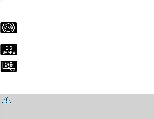
Anti-lock Brake System (ABS)
This system helps you maintain steering control during emergency stops
by keeping the brakes from locking.
The ABS lamp momentarily illuminates when the ignition is
turned on. If the light does not illuminate during start-up,
remains on or flashes, the ABS may be disabled and may need
to be serviced.
If the ABS is disabled, normal braking is still effective. If the
brake warning lamp illuminates, have your brake system
serviced immediately.
If a PLC trailer is connected when the ignition is switched on,
the trailer ABS light also illuminates. If the light fails to
illuminate, remains on after the vehicle is started or continues
to flash, have the system serviced immediately.
FULL POWER BRAKE SYSTEM
WARNING: If the red BRAKE warning lamp in the instrument
cluster remains illuminated after engine start up, this indicates a
system failure in the Full Power Brake System. Stop the vehicle safely
as soon as possible and seek service immediately.
This system incorporates standard braking, an anti-lock braking system
(ABS) and optional Power Park Brake into one fully-integrated hydraulic
brake system. With the Full Power Brake System, braking energy is
stored, similar to an air brake system, resulting in faster response times
and shorter stopping distances. This is accomplished using motor and
pump assemblies that pressurize the system by pumping brake fluid into
accumulators. This is similar to the air compressor of an air brake system
pressurizing the air tanks. The system includes a master cylinder that
provides the normal pedal feel and transfers the pedal force, via brake
fluid, to the main components of the system.
Note: The motor and pumps run momentarily with the ignition switch in
the on or run position, or in the off position with the brake pedal
pressed.
Note: During normal driving, the pump and motors may be heard
replenishing the accumulators. This is a normal function of the system.
148 Brakes
2013 F-650/750 (f67)
Owners Guide gf, 2nd Printing, March 2013
USA (fus)
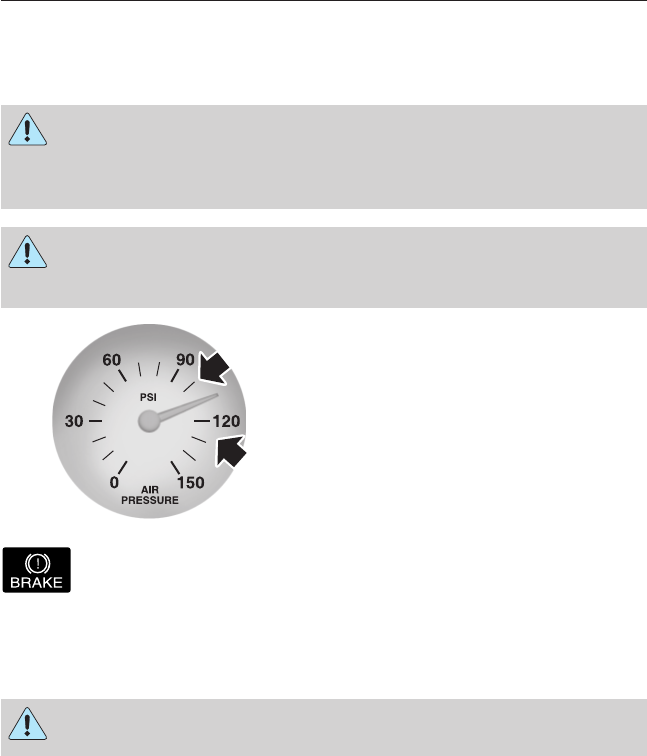
AIR BRAKES
After starting the engine, give the air compressor time to build up the air
pressure to 60 psi (414 kPa) before moving the vehicle.
WARNING: Do not drive or continue to drive if the low air
pressure buzzer is sounding or the brake warning light is lit.
These warnings indicate that air pressure is not to normal operating
level. Continued use of the vehicle could result in loss of braking ability.
WARNING: Avoid repeated light application of the brake pedal.
This depletes air pressure faster and could result in loss of
braking capability.
Periodically check the air pressure
gauge while driving. Pressure should
range between approximately
100–125 psi (690–862 kPa). The air
compressor governor cut-in and
cut-out pressure settings are set at
the factory and are not adjustable.
When air pressure is insufficient (below 60 psi [414 kPa]), a
warning light illuminates and a buzzer sounds when the ignition
is in the on position.
This condition may be caused by excessive brake applications depleting
the system air pressure. If this condition occurs, stop driving the vehicle
until the compressor has fully recharged the air system.
WARNING: Do not move the vehicle when the air pressure is
insufficient because the brake system may be inoperative.
Select a gear ratio to help slow your vehicle before descending grades.
Supplement with brakes as required to safely slow the vehicle and avoid
overspeeding the engine.
Brakes 149
2013 F-650/750 (f67)
Owners Guide gf, 2nd Printing, March 2013
USA (fus)
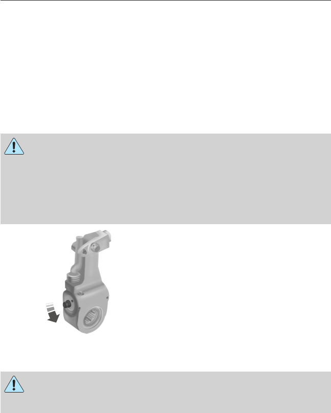
Air Chamber Stroke Indication
Air chamber push rods have orange stroke indicator markers that warn
when the braking system requires adjustment or repair. The orange
stripe is painted on the air chamber push rod at the slack adjuster stroke
dimension which requires service when visible during brake application.
Air brake inspection and adjustment or repairs should be performed by a
qualified service technician in accordance with the instructions in the
service manual.
Cam Brakes - Automatic Slack Adjusters
WARNING: Do not manually adjust the automatic slack adjusters
to correct excessive push rod stroke as it may result in reduced
brake effectiveness and a vehicle crash. Excessive push rod stroke
indicates that a problem exists with the automatic adjuster, with the
installation of the adjuster, or with foundation brake components that
manual adjustment does not remedy. Seek service from a qualified
facility for excessive push rod stroke.
Standard air brakes (cam) are
equipped with automatic brake
adjusters. Automatic adjustment
occurs during brake applications.
Inspect brakes for proper
adjustment at the intervals listed in
the Scheduled Maintenance
chapter.
Emergency Air Brake
WARNING: Do not continue to operate the vehicle with a failure
of one of the brake systems. Take the vehicle to your dealer for
service immediately.
All vehicles are equipped with a dual brake system. In the unlikely event
of a failure of one system, the second system functions for emergency
stopping. These systems are all controlled by the brake pedal in the
same manner as for normal stops.
150 Brakes
2013 F-650/750 (f67)
Owners Guide gf, 2nd Printing, March 2013
USA (fus)

HINTS ON DRIVING WITH ANTI-LOCK BRAKES
When the system is operating, the brake pedal pulses and may travel
further. Maintain pressure on the brake pedal. You may also hear a noise
from the system. This is normal.
The ABS does not eliminate the dangers inherent when:
•You drive too closely to the vehicle in front of you.
•Your vehicle is hydroplaning.
•You take corners too fast.
•The road surface is poor.
EXHAUST BRAKE (IF EQUIPPED)
WARNING: The exhaust brake is not recommended for use on
slippery or low traction road surfaces. Under these conditions a
loss of vehicle control could occur.
Note: Installing an exhaust or auxiliary brake does not necessarily
protect the engine from exceeding maximum governed speed. The
primary brakes should be used to make sure the engine never exceeds
maximum governed speed under any conditions.
Note: Before starting the engine, make sure that the exhaust brake
switch is pushed down to the off position. Do not turn the exhaust brake
on until the engine has reached normal operating temperature.
Note: Maximum exhaust brake performance is related to the type of
transmission your vehicle is equipped with.
Note: Engine speed has a major influence of retarding performance.
When engine speed is maintained at the maximum allowable level, the
exhaust brake operates at peak performance.
Note: Manual transmissions should be downshifted to the lowest gear
possible, without exceeding the maximum RPM limit of the engine.
This maximizes the exhaust brake’s retarding effect.
Note: Exhaust brakes operate effectively with automatic transmissions,
but performance varies with engine speed and the gear selected by the
transmission.
Brakes 151
2013 F-650/750 (f67)
Owners Guide gf, 2nd Printing, March 2013
USA (fus)

An exhaust brake is an auxiliary braking system that assists, but does
not replace, the primary service brake system. It is intended to help
control vehicle speed. It is not a vehicle stopping device.
A switch on the instrument panel,
in combination with the accelerator
and clutch pedal, allows the
operator to make maximum use of
the exhaust brake in the following
conditions:
•off-highway driving
•mountain driving
•heavy traffic
•high-speed highway driving.
To operate the brake, push the switch up to turn it on. Push the switch
down to turn it off.
While approaching a steep grade, make sure that the exhaust brake
switch is in the on position. The exhaust brake begins working as soon as
you remove your foot from the accelerator pedal.
Before descending a hill or steep grade, always select the proper gear. If
the transmission is taken out of gear while descending, it is possible that
you cannot select another gear because of maximum RPM being
governed.
Make sure the engine speed does not exceed the maximum allowable
engine RPM. Exceeding the maximum allowable engine RPM can result
in damage to the engine. Apply the service brakes to reduce the engine
RPM or make a slower descent by using a lower gear.
While going down the grade, use a low enough gear to descend safely
with a minimum application of the service brakes. As a general guideline,
use the same gear as you use to ascend the hill.
152 Brakes
2013 F-650/750 (f67)
Owners Guide gf, 2nd Printing, March 2013
USA (fus)
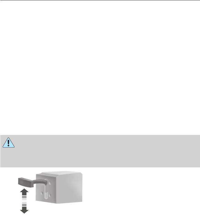
Exhaust Brake Operating Characteristics
When you remove your feet from both the accelerator and clutch pedals
and the exhaust brake switch is in the on position, the exhaust brake is
activated. The following conditions exist if the brake is operating properly:
•A slight change in engine sound when the exhaust brake is activated.
•A smooth braking effect. Do not expect a retarding effect similar to
sudden, hard application of the service brakes.
•The retarding force possibly felt acting against your body when the
brake is applied (depending on the grade and vehicle load). This force
is actually preventing the vehicle from going much faster.
•Engine temperature remaining in the normal operating range.
•The tachometer showing a drop in engine RPM (depending on grade
and vehicle load) during a descent.
•A decrease in road speed when the exhaust brake is applied during a
descent, except when the vehicle is carrying a heavy load or the grade
is extremely steep. In these instances, you may need to apply the
service brakes occasionally.
TRAILER BRAKES
Trailer Brake Hand Control (If Equipped)
WARNING: The hand control should never be used to apply
the brakes when the tractor and trailer are parked unattended.
Air may leak from the system and the vehicle could possibly move,
resulting in possible property damage, personal injury or death.
The hand control is located on the
right-hand side of the instrument
panel. It is used to apply the
trailer service brakes which are
independent of the truck or tractor
service brakes.
It operates a valve that provides gradual control of air pressure applied.
When the valve is only partially applied, the trailer brakes can be
overridden by pressing fully on the brake pedal.
To apply the trailer brakes using the hand control, move the lever
downward. The further the lever is pushed down, the greater the air
pressure is applied to the brakes. The lever remains in place until
manually moved.
To release the trailer brakes, move the lever up completely.
Brakes 153
2013 F-650/750 (f67)
Owners Guide gf, 2nd Printing, March 2013
USA (fus)
Trailer Air Supply and Parking Brake Modular Controls
(If Equipped)
The trailer air supply valve delivers
air to the trailer supply and
automatically pops out, shutting off
the trailer supply, if pressure
decreases to approximately 35 psi
(249 kPa).
The parking brake controls the
spring brakes on the tractor. When
the knob is pulled out, it causes the
trailer supply valve to pop out,
applying both the tractor and trailer
parking brakes. The trailer brakes
may be independently released by
pushing only the trailer air supply
valve in.
Initial Charge
With the air system completely discharged, both knobs (A and B) are
out. When the air pressure reaches 70 psi (483 kPa), the trailer air
supply (A – red knob) may be pushed in and should stay in, charging the
trailer air system and releasing the trailer brakes.
B
A
B
A
154 Brakes
2013 F-650/750 (f67)
Owners Guide gf, 2nd Printing, March 2013
USA (fus)
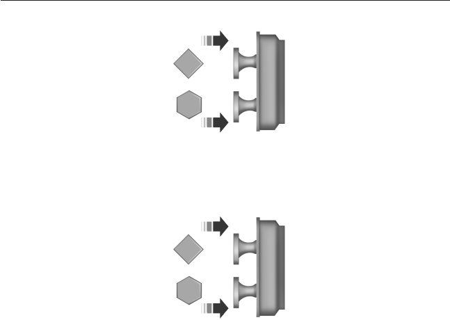
The parking brake (B – yellow knob) can now be pushed in and supply
air to the tractor spring brakes, releasing them.
Normal Driving Position
With both knobs pushed in, air is supplied to both trailer and tractor
spring brakes and all brakes are released.
B
A
B
A
Brakes 155
2013 F-650/750 (f67)
Owners Guide gf, 2nd Printing, March 2013
USA (fus)
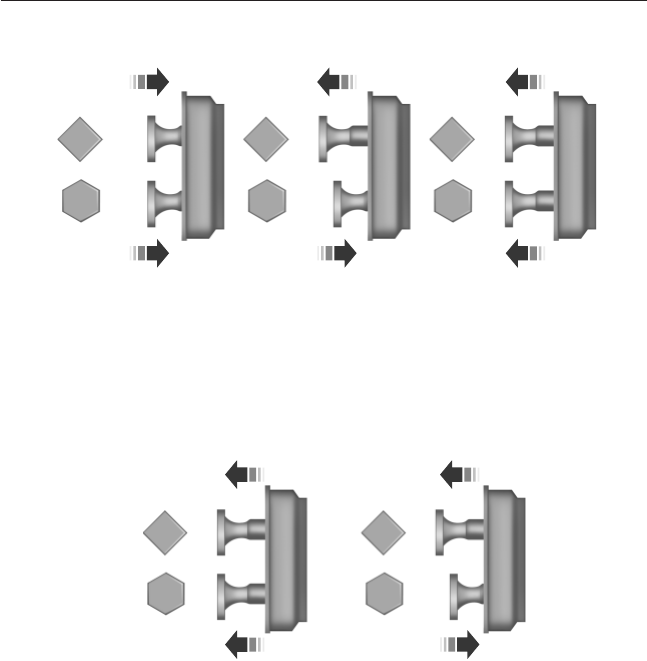
System Park
With both knobs pushed in (normal driving position), the parking brakes
for both the tractor and trailer can be applied by pulling the parking
brake knob (B) out, exhausting air from the tractor spring brakes,
simultaneously causing the trailer air supply valve to pop out, applying
the trailer brakes.
Trailer Charge
If both knobs are out, and you want to recharge the trailer while leaving
the tractor spring brakes applied, the trailer air supply (A) can be
pushed in to recharge the trailer air supply line. This mode may also be
used to park a combination vehicle with tractor spring brakes.
B
A
B
A
B
A
B
A
B
A
156 Brakes
2013 F-650/750 (f67)
Owners Guide gf, 2nd Printing, March 2013
USA (fus)
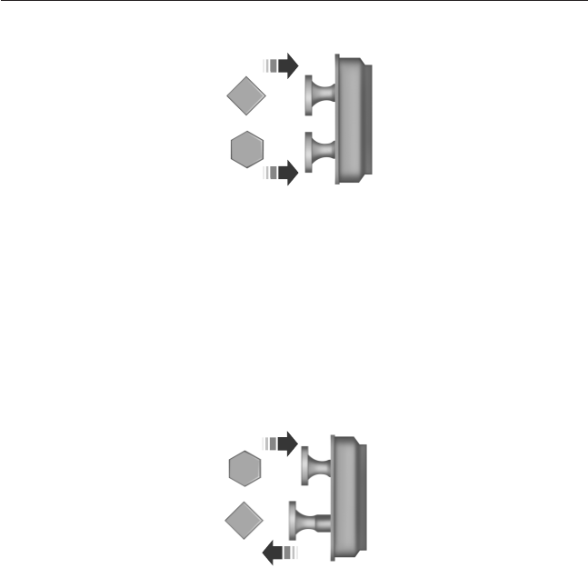
Automatic Application
If both knobs are pushed in and the brake system air pressure is reduced
to approximately 35 psi (249 kPa), the trailer air supply (A) knob
automatically pops out applying the emergency or parking brakes on the
trailer. If the trailer air supply (A) knob is manually held in and the air
pressure is reduced to approximately 30 psi (207 kPa), a tripper piston
within the valve moves, exhausting the trailer air supply, applying the
trailer brakes. Further reduction of air pressure, while holding the trailer
air supply knob in, causes the parking brake knob to pop out at 25 psi
(172 kPa).
Actuation of Trailer Park (Emergency) or Tractor Bobtail Position
To actuate the trailer brakes only, pull out the trailer air supply knob
(A). The trailer brakes are now applied whether emergency or spring
brakes are used on the trailer.
This mode is also used when the tractor or truck with trailer is used
during bobtail operation.
B
A
B
A
Brakes 157
2013 F-650/750 (f67)
Owners Guide gf, 2nd Printing, March 2013
USA (fus)
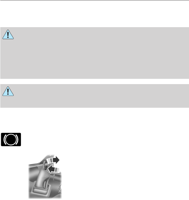
PARKING BRAKE
Hydraulic Brakes
WARNING: Do not use the gearshift selector in place of the
parking brake. Always set the parking brake fully AND make sure
the gearshift selector is in position Rfor vehicles equipped with a
manual transmission or position P (if equipped) or Nfor vehicles
equipped with an automatic transmission. Use of wheel chocks is also
recommended in hilly or off-road usage. Unexpected and possible
sudden vehicle movement may occur if these precautions are not taken.
WARNING: If the parking brake is fully released but the parking
brake warning lamp remains illuminated, the brakes may not be
working properly. See your dealer or a qualified service technician.
Apply the parking brake whenever the vehicle is parked. To set the
parking brake, pull the handle up until it snaps into the locked position.
When the parking brake is out of adjustment, seek service immediately.
The parking brake warning lamp in the instrument cluster
illuminates, and remains illuminated (when the ignition is
turned on), until the parking brake is released.
Push the palm release lever (A) on
the parking brake handle (B) and
push down as far as possible to
release the brake. Driving with the
parking brake on causes the brakes
to wear out quickly and reduces
fuel economy.
The parking brake is not recommended to stop a moving vehicle.
However, if the normal brakes fail, the parking brake can be used to stop
your vehicle in an emergency. Since the parking brake only applies
retardation to the rear wheels, the vehicle’s stopping distance increases
greatly and the handling of your vehicle is adversely affected.
Power Park (Hydraulic Brake Vehicles Only)
This feature uses a brake chamber mounted on the chassis to power a
spring-applied, hydraulically-released driveline parking brake.
P
A
B
158 Brakes
2013 F-650/750 (f67)
Owners Guide gf, 2nd Printing, March 2013
USA (fus)

The Power Park Brake is controlled by the park brake dash-mounted,
yellow knob-type switch. The switch has three positions: apply (out),
neutral (central), and release (in). The switch is spring-loaded to return
to the neutral (central) position after being pushed or pulled.
There is no visual indication at the knob that the park brake is
applied or released; check the instrument cluster. If the light is
illuminated, the parking brake is applied.
Applying the Parking Brake
Pull the yellow, dash-mounted parking brake knob. The parking brake
light illuminates indicating that the parking brake has been successfully
set.
Note: If the light blinks and a warning chime sounds when the control
knob is pulled, the parking brake is not functioning properly. Seek
immediate service from your dealer. See Parking brake warning
system in this section.
Releasing the Parking Brake
WARNING: Hold the brake pedal down while moving the
gearshift lever from position to position. If the brake pedal is not
held down, the vehicle may move unexpectedly resulting in property
damage, personal injury or death.
Note: Read and understand the following steps and perform them
whenever you prepare to drive the vehicle.
Note: The parking brake does not disengage unless sufficient system air
pressure is available.
If your vehicle is equipped with a dash-mounted push button (Allison
3000 Series) or steering column-mounted (Allison 2200 and 2500) gear
selector:
1. Press and hold the service brake pedal while the engine is running.
2. Select the appropriate drive gear.
3. Push and hold the yellow, dash-mounted parking brake knob until the
parking brake light turns off, then release.
If your vehicle is equipped with a manual transmission:
1. Press and hold the service brake pedal while the engine is running.
2. Press and hold the clutch pedal.
3. Select the appropriate drive gear.
4. Push and hold the yellow, dash-mounted parking brake knob until the
parking brake light turns off, then release.
P
Brakes 159
2013 F-650/750 (f67)
Owners Guide gf, 2nd Printing, March 2013
USA (fus)

Parking Brake Light Illumination Due to Low Air Pressure
If at any time during vehicle operation air pressure becomes too low, the
parking brake may apply and the parking brake light turns on.
If the parking brake is applied due to low air pressure, immediate service
is required to the parking brake system.
Parking Brake Warning System
If the parking brake light blinks and a chime sounds when pulling the
yellow control knob out, this indicates the parking brake is not
functioning properly. Seek service for the parking brake immediately.
With the ignition key not in the run position:
•A chime sounds if the parking brake remains released (or in an
unknown state). The chime stops in approximately eight minutes or
until the parking brake is applied. Seek service for the parking brake
immediately.
Diesel engines: Parking brake light operation (the light only works
when the ignition key is in the run position):
•On: Parking brake applied.
•Off: Parking brake released and no faults or malfunctions.
•Blink and chime: Parking brake released (or in an unknown state)
and faults or malfunctions exist.
Releasing Spring Manually
WARNING: Do not attempt to disassemble the parking brake
chamber under any circumstances. The high spring load may
cause serious injury.
WARNING: Block the wheels to help prevent the vehicle from
moving.
WARNING: Unexpected and possibly sudden vehicle movement
may occur if these precautions are not taken.
If hydraulic pressure is released from the spring brake chamber the
power spring applies the brake and, unless hydraulic pressure can be
re-established, the spring brake must be released as follows in order to
move the vehicle.
160 Brakes
2013 F-650/750 (f67)
Owners Guide gf, 2nd Printing, March 2013
USA (fus)
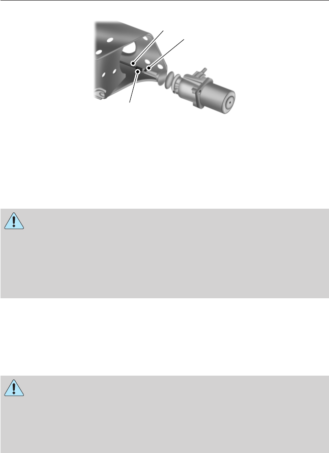
Loosen the jam nut (A) and un-thread the adjustment rod (B) from the
chamber to reduce tension on the cable (C). Continue to un-thread the
adjustment rod all the way and remove it from the chamber. The nut and
shaft are metric.
Air Brakes
WARNING: Do not use the gearshift selector in place of the
parking brake; unexpected and possible sudden vehicle
movement may occur if these precautions are not taken. Always set the
parking brake fully AND make sure the gearshift selector is in position
Rfor vehicles equipped with manual transmission or position N(except
Allison 2200 transmission) or P(Allison 2200 transmission) for vehicles
with automatic transmission.
If the service brakes should fail to operate while the vehicle is in motion,
you can make an emergency stop with the parking brake. Since the
parking brake only applies stopping power to the rear wheels, the
vehicle’s stopping distance greatly increases and the handling of the
vehicle is adversely affected. Repairs should be made immediately to an
inoperative air brake system circuit.
WARNING: This control is used for parking only. Do not leave
the vehicle unattended after setting the parking brake without
placing the transmission inposition Rfor vehicles equipped with manual
transmission or position N(except Allison 2200 transmission) or P
(Allison 2200 transmission) for vehicles with automatic transmission.
Use of wheel chocks is also recommended in hilly or off-road usage.
CA
B
Brakes 161
2013 F-650/750 (f67)
Owners Guide gf, 2nd Printing, March 2013
USA (fus)
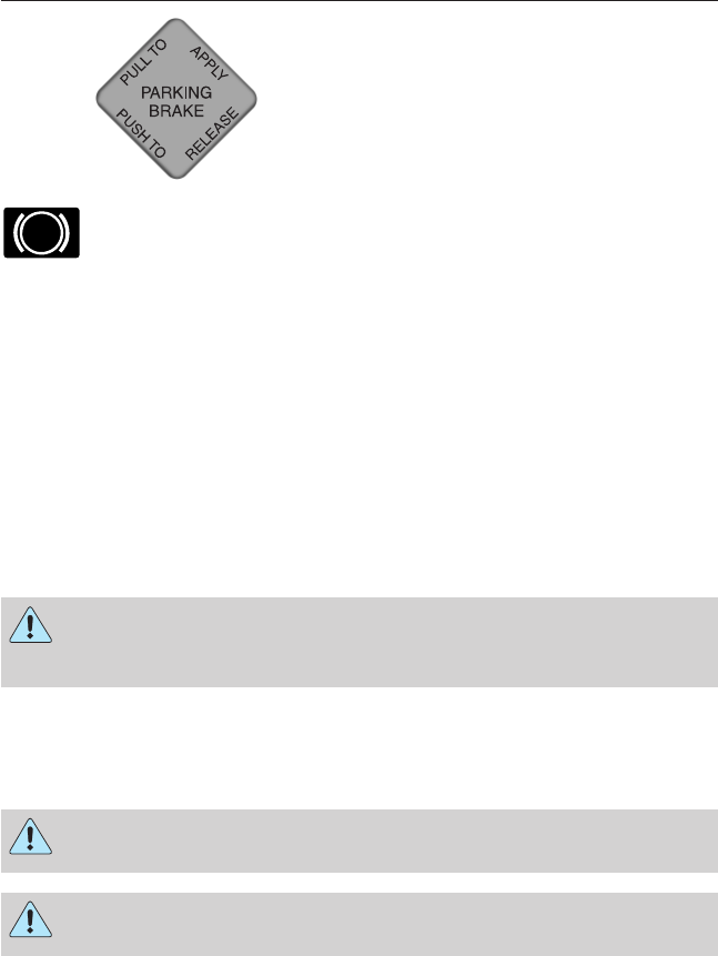
Pull the yellow parking brake knob
out to apply the parking brake.
Push the knob in to release the
parking brake.
The parking brake light illuminates and remains illuminated
(when the ignition is turned to the on position) until the
parking brake is released.
Releasing Spring Brake with Air Pressure
The air system in all vehicles with spring-actuated rear wheel parking
brakes is equipped with a tank valve located on the supply or service air
tank for connection to an outside air supply. The valve permits the
system to be recharged with air from an outside source, releasing the
spring-actuated parking brakes. The vehicle may then be towed in an
emergency.
An outside air source can be used only if the protected system is in
operating condition. If air pressure cannot be restored in the protected
air system, the spring-actuated brakes must be released manually.
Releasing Spring Manually
WARNING: Do not attempt to disassemble the parking brake
chamber under any circumstances. The high spring load may
cause serious injury if the chamber clamps are removed.
If air pressure is released from the spring brake chamber the power
spring applies the brake and, unless air pressure can be re-established,
the spring brake must be released as follows in order to move the
vehicle.
WARNING: Block the wheels to help prevent the vehicle from
moving.
WARNING: Unexpected and possibly sudden vehicle movement
may occur if these precautions are not taken.
P
162 Brakes
2013 F-650/750 (f67)
Owners Guide gf, 2nd Printing, March 2013
USA (fus)
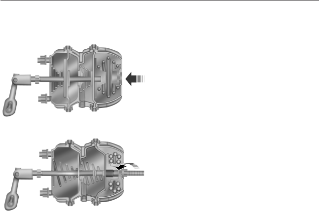
Impact wrenches should not be used as they may damage the piston and
prevent proper caging of the spring. Do not apply more than
50 foot-pounds (68 newton-meters) torque to the release bolt nut.
1. Remove the stud tool and nut
from the carrying pocket on the
brake chamber assembly.
2. Remove the access plug from the
end of the spring chamber.
3. Insert the release stud through
the opening in the chamber and
into the spring pressure plate.
4. Turn the release stud
1
⁄
4
-turn to
engage the stud tangs with the slot
in the pressure plate. Keep the stud
engaged and install the nut on the
release stud.
5. Tighten the nut until the spring
is fully caged and the brakes are
released. Do not loosen or remove
the release stud and nut unless the brake chamber is completely
assembled and is securely clamped.
6. When the air pressure is restored, unscrew and remove the release
stud and install in the carrying pocket. Install the access plug.
Brakes 163
2013 F-650/750 (f67)
Owners Guide gf, 2nd Printing, March 2013
USA (fus)
PRINCIPLES OF OPERATION
The traction control system helps avoid drive wheel spin and loss of
traction.
If your vehicle begins to slide, the system applies the rear brakes to
individual wheels and, when needed, reduces engine power at the same
time. If the wheels spin when accelerating on slippery or loose surfaces,
the system reduces engine power in order to increase traction.
Note: The system does not apply the brakes when vehicle speed is
above 25 mph (40 km/h).
USING TRACTION CONTROL
WARNING: Aggressive driving in any road conditions can cause
you to lose control of your vehicle increasing the risk of severe
personal injury or property damage. The occurrence of a traction
control event is an indication that at least some of the tires have
exceeded their ability to grip the road; this may lead to an increased
risk of loss of vehicle control, vehicle rollover, personal injury and
death. If you experience a severe road event, SLOW DOWN.
Press the switch to select Off Road
or Mud/Snow traction mode. This is
beneficial when the vehicle is stuck
in snow or on a slippery road
surface. This mode allows excess
wheel spin to dig the vehicle out
and allows you to rock the vehicle.
Press the switch again to select standard traction control. Standard
traction control is automatically selected at the next ignition cycle.
MUD/SNOW
TRACTION
164 Traction Control
2013 F-650/750 (f67)
Owners Guide gf, 2nd Printing, March 2013
USA (fus)

System Indicator Light
Note: If the traction control light does not flash during a traction control
event or stays illuminated, the system is not functioning properly. Take
your vehicle to your dealer for service.
During traction control operation, the traction control light
flashes rapidly and the engine does not rev-up when you press
further on the accelerator. This is normal and is no reason for
concern.
In Off Road or Mud/Snow mode, the traction control light illuminates and
flashes slowly. If a traction event occurs, in either mode, the light flashes
rapidly.
Traction Control 165
2013 F-650/750 (f67)
Owners Guide gf, 2nd Printing, March 2013
USA (fus)
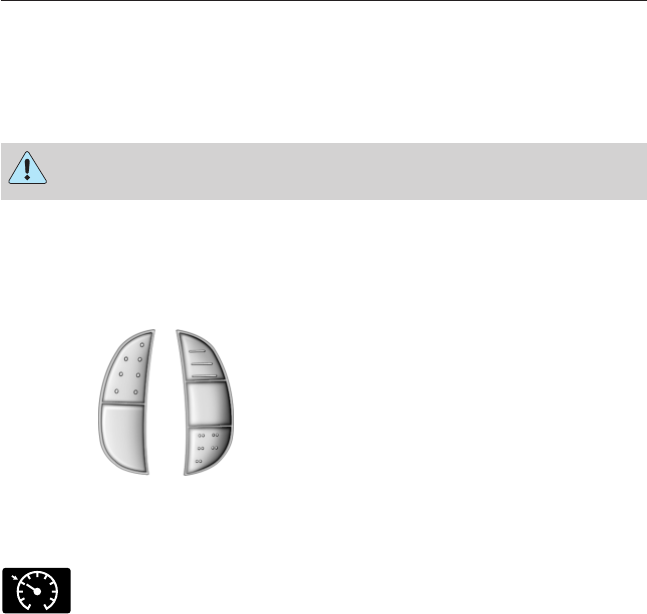
PRINCIPLES OF OPERATION
Cruise control lets you maintain a set speed without keeping your foot
on the accelerator pedal.
USING CRUISE CONTROL
WARNING: Do not use cruise control in heavy traffic or on
roads that are winding, slippery or unpaved.
Note: Vehicle speed may vary momentarily when driving up or down a
steep hill. Apply the brakes if your vehicle speed increases above the set
speed while driving downhill.
Note: Cruise control will disengage if your vehicle speed decreases more
than 10 mph (16 km/h) below your set speed while driving uphill.
The cruise controls are located on
the steering wheel.
Switching On Cruise Control
Press and release ON.
The indicator will turn on in the instrument cluster.
Setting a Speed
1. Accelerate to the desired speed.
2. Press and release SET ACCEL.
3. Take your foot off the accelerator pedal.
RES
SET
ACCEL
COAST
ON
OFF
166 Cruise Control
2013 F-650/750 (f67)
Owners Guide gf, 2nd Printing, March 2013
USA (fus)

Changing the Set Speed
•Press and hold SET ACCEL to increase or COAST to decrease the
set speed. Release the button when you reach the desired speed.
•Press and release SET ACCEL to increase or COAST to decrease.
The set speed will change in approximately 1 mph (2 km/h)
increments.
•Press the accelerator pedal or brake pedal until you reach the desired
speed. Press and release SET ACCEL.
Canceling a Set Speed
Tap the brake pedal. The set speed will not be erased.
Resuming a Set Speed
Press and release RES.
Switching Off Cruise Control
Note: The set speed is erased when you turn off cruise control.
Press OFF or turn off the ignition.
Cruise Control 167
2013 F-650/750 (f67)
Owners Guide gf, 2nd Printing, March 2013
USA (fus)

OPERATING YOUR VEHICLE
General Information
•Start the vehicle in motion by using the highest gear speed in the
transmission that lets the engine easily start the load without slipping
the clutch.
•Accelerate smoothly and evenly. Rapid acceleration increases fuel
consumption without increasing engine performance.
•When approaching a hill, press the accelerator smoothly to start the
incline at full power, then shift down as needed to maintain vehicle
speed.
•When going down a hill, or long steep grades, prevent overspeeding
of the engine. Normally, choose the same gear to descend the hill that
you use to ascend the hill. The engine governor has no control over
engine speed when it is being pushed by a loaded vehicle.
•Operate in a gear that permits an engine speed not in excess of the
maximum governed speed or high-idle RPM (no load).
•
Always shift to a lower gear at high altitudes to prevent engine smoking.
Backing Up
WARNING: All vehicles have blind spots. To reduce the risk of
severe injury or property damage, never move your vehicle to the
side or rear or change lanes without being sure your way is clear on
both sides and to your rear.
WARNING: To reduce the risk of the possibility of personal
injury while backing up the vehicle, always be sure your vehicle’s
path is clear.
Before backing up your vehicle, be sure you can do so safely. If anything
behind the cab limits your view, do not rely on mirrors alone to ensure
that your intended path is clear. If other people are in the vicinity, have
someone standing well behind your vehicle and outside of your intended
path (visible through an exterior mirror) guide you as you back up.
Although OSHA or some governmental regulations may require the use
of an electrical or mechanical back up alarm to warn bystanders, such an
alarm does not guarantee that the intended path is clear. When in doubt,
get out of the vehicle and visually check the intended path is clear. Back
up slowly as to allow others time to move, if necessary.
If an electrical back up alarm is installed, it should be connected to the
back up lamp circuit.
168 Driving Aids
2013 F-650/750 (f67)
Owners Guide gf, 2nd Printing, March 2013
USA (fus)

Parking
WARNING: When parking your vehicle, do not leave the
transmission in gear; if the key is in the on position and the
vehicle rolls, the engine could start. Failure to follow these instructions
could result in an unattended vehicle moving, possibly causing personal
injury or property damage.
Always use the parking brake. When parking on a grade, block the
wheels and turn the front wheels to one side so that if the vehicle rolls,
the front tires act against the curb to stop the vehicle. The front wheels
are more effective at stopping a rolling vehicle than the rear wheels.
Cold Weather
Note: Idling in cold weather does not heat the engine to its normal
operating temperature. Long periods of idling in cold weather can cause
a build-up of heavy deposits of carbon and rust on valve stems causing
them to stick which, in turn, can cause valvetrain damage.
Note: The use of winter fronts, or other air-restrictive devices mounted
in front of the radiator on vehicles with chassis-mounted charge air
coolers, are not recommended unless extremely cold weather conditions
exist. Airflow restriction can cause high exhaust temperatures, power
loss, excessive fan usage and a reduction in fuel economy. If you must
use a winter front, the device should have a permanent opening of at
least 120 square inches (774 square centimeters) directly in line with the
fan hub.
For best engine operation in temperatures of 32°F (0°C) or lower:
•Make sure the batteries are the correct type and are fully charged.
Check other electrical components to make sure they are in optimum
condition.
•Use a permanent-type engine coolant to protect the engine against
damage from freezing.
•If your vehicle is equipped with a water-fuel separator, drain it daily.
Fill the fuel tank at the end of daily operation to prevent
condensation in the fuel system.
•Use the proper engine oil and maintain it at its proper level.
•At temperatures of –4°F (–20°C) or below, it is recommended that
you use a crankcase-mounted coolant heater to improve cold engine
starting.
•If operating in arctic temperatures of –20°F (–29°C) or lower, consult
your truck dealer for information about special cold weather
equipment and precautions.
Driving Aids 169
2013 F-650/750 (f67)
Owners Guide gf, 2nd Printing, March 2013
USA (fus)

Hot Weather
•Use a permanent-type engine coolant to protect the engine against
damage from overheating.
•Fill the fuel tank at the end of daily operation to prevent
condensation in the fuel system.
•Keep external surfaces of the engine, radiator, charge air cooler, A/C
condenser and accessories clean to avoid dirt build-up.
•Above normal coolant temperatures could be experienced while
driving in a transmission gear ratio which lugs the engine. To correct
this problem, engine speed should be increased by downshifting into
the next lower gear.
STEERING
Your vehicle is equipped with power steering. Power steering uses energy
from the engine to decrease the driver’s effort in steering the vehicle.
To help prevent damage to the power steering pump:
•Never hold the steering wheel to the extreme right or the extreme
left for more than a few seconds when the engine is running.
•Do not operate the vehicle with the power steering pump fluid level
below the ADD mark on the MAX. COLD side of the power steering
reservoir dipstick.
•Some noise is normal during operation. If the noise is excessive,
check for low power steering pump fluid level before seeking service
by your authorized dealer.
•Heavy or uneven steering efforts may be caused by low power
steering pump fluid level. Check for low power steering pump fluid
level before seeking service by your authorized dealer.
•Do not fill the power steering pump reservoir above the FULL mark
on the MAX. HOT side of the power steering reservoir dipstick, as
this may result in leaks from the reservoir.
If the power steering system breaks down (or if the engine is turned
off), you can steer the vehicle manually, but it takes more effort.
If the steering wanders or pulls, check for:
•underinflated tire(s) on any wheel(s)
•uneven vehicle loading
•high crown in center of road
•high crosswinds
•wheels out of alignment
•loose or worn suspension components.
170 Driving Aids
2013 F-650/750 (f67)
Owners Guide gf, 2nd Printing, March 2013
USA (fus)

AIR SUSPENSION (IF EQUIPPED)
Note:
The vehicle must not be operated without air in the suspension
springs. Operating the vehicle without air in the suspension springs damages
the suspension, degrades ride performance and may cause property damage.
The air suspension system automatically adjusts to different loads to
maintain a constant frame height, allows for ease of vehicle loading and
provides improved vehicle ride and increased driver comfort.
Air Suspension Dump Switch
Note: The suspension dumps air when the ignition is in the accessory or
on position, but fills only when the ignition is in the on position.
The system is controlled by a switch
located in the overhead switch
pack. It operates only when the
ignition is in the accessory or on
position and the air tanks have
sufficient pressure to fill the air
springs. When the ignition is turned
off, the suspension remains in
whatever state it was last set.
Pressing the lower portion of the switch exhausts air from the air
springs, lowering the frame for loading. Pressing the upper portion of the
switch fills the air springs so the vehicle remains at normal ride height.
System Indicator Light
The air suspension indicator light illuminates when the switch
has been activated to release air pressure in the rear air shocks.
Never drive the vehicle when the warning lamp is illuminated
and there is low (or no) air pressure in the shocks.
Connecting and Disconnecting a Trailer with Air Suspension and
Air Suspension Dump Switch
When connecting to a trailer:
•Press the lower portion of the switch to exhaust air from the air
suspension system.
•Press the upper portion of the switch, then raise the landing gear
after making the connection to the trailer.
When disconnecting the trailer:
•Lower the landing gear, then press the lower portion of the switch.
•Disconnect the brake hoses, trailer-side and rear light connectors,
then pull the release lever on the fifth-wheel.
CK
SUSP
Driving Aids 171
2013 F-650/750 (f67)
Owners Guide gf, 2nd Printing, March 2013
USA (fus)
The upper portion of the switch must be pressed before operating with a
trailer or operating in the bobtail mode.
Suspension Conversions
WARNING: When operating a loaded vehicle, the driver must
keep all adjustable axles on the ground at all times, supporting
their share of the vehicle’s load. Failure to do so can overload other
axles, tires, wheels, springs, steering components, brakes and frames,
resulting in early component failure, loss of vehicle control, possible
property damage and personal injury.
It is not recommended, or approved, that suspension conversions be
performed. However, it is understood that, on occasion, aftermarket
add-on suspensions are installed by others on the truck chassis which
allow operator control for weight transfer from other axles (i.e., air lift
axles).
UPFITTER CONTROLS (IF EQUIPPED)
The upfitter option package
provides four switches, mounted in
the center of the instrument panel.
These switches are always on
whether the engine is running or
not. Make sure you put the switches
in the off position to avoid draining
the battery when the vehicle is not
being used. It is recommended that the engine remain running to
maintain battery charge when using the upfitter switches for extended
duration or higher current draws. (This is even more important for
vehicles with a diesel engine since the glow plugs are also draining
battery power when the ignition key is in the on position.)
Each switch provides 10 amps of electrical battery power for a variety of
personal or commercial uses.
There is also a relay box located on the passenger side end of the
instrument panel. See your authorized dealer for service.
Switch access location is in a connector located in the engine
compartment. More detailed information can be found at
https://www.fleet.ford.com/truck/bbas/.
AUX 1 AUX 2 AUX 3 AUX 4
172 Driving Aids
2013 F-650/750 (f67)
Owners Guide gf, 2nd Printing, March 2013
USA (fus)
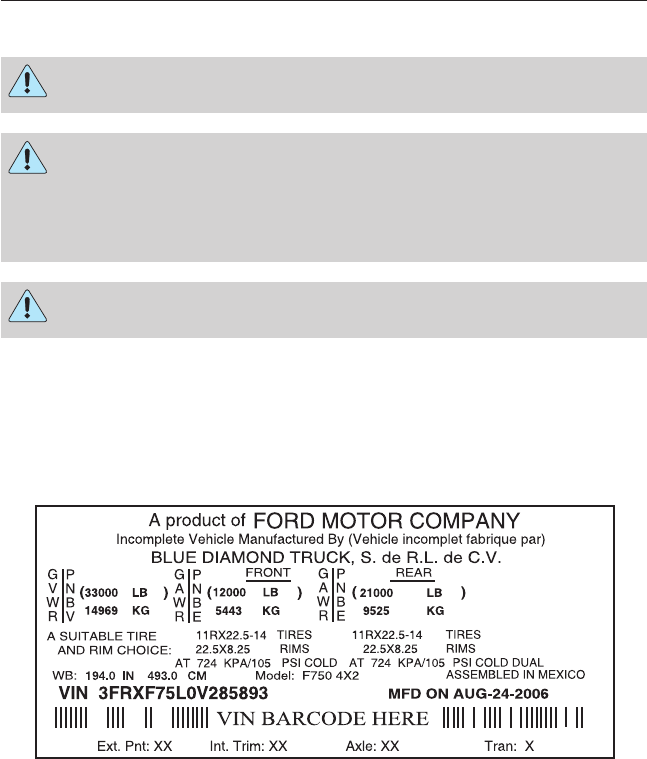
LOAD LIMIT
WARNING: Do not exceed the GVWR or the GAWR specified on
the Safety Compliance Certification Label.
WARNING: Do not use replacement tires with lower load
carrying capacities than the originals because they may lower the
vehicle’s GVWR and GAWR limitations. Replacement tires with a higher
limit than the originals do not increase the GVWR and GAWR
limitations.
WARNING: Exceeding any vehicle weight rating limitation could
result in serious damage to the vehicle and/or personal injury.
Every vehicle manufactured by Ford Motor Company is supplied with
information on the Safety Compliance Certification Label, located on
either the B-pillar or the driver’s door edge, listing the maximum loading
for the vehicle (GVWR), and its axle systems (GAWR) at the tire to
ground interface.
Under no circumstances should your vehicle be loaded in excess of the
GVWR or GAWR. It is the operator’s responsibility to ensure that neither
the axle capacities, spring capacities, tire capacities nor the vehicle rated
GVWR is exceeded.
Load Carrying 173
2013 F-650/750 (f67)
Owners Guide gf, 2nd Printing, March 2013
USA (fus)

Unloaded or Lightly Loaded Vehicles
WARNING: When operating empty or lightly loaded, sudden or
hard braking may induce wheel lockup with loss of vehicle
control and the possibility of accident and serious injury, especially on
wet or slippery road surfaces.
The braking system has been designed to safely stop your vehicle when
fully loaded to its GVWR.
174 Load Carrying
2013 F-650/750 (f67)
Owners Guide gf, 2nd Printing, March 2013
USA (fus)

TOWING A TRAILER
WARNING: Do not exceed the GVWR or the GAWR specified on
the certification label.
WARNING: Towing trailers beyond the maximum recommended
gross trailer weight exceeds the limit of the vehicle and could
result in engine damage, transmission damage, structural damage, loss
of vehicle control, vehicle rollover and personal injury.
Your vehicle’s load capacity is designated by weight, not by volume, so
you cannot necessarily use all available space when loading a vehicle.
Second-unit bodies are not included in maximum trailer weight ratings.
The weight of the additional body must be subtracted from the maximum
trailer weight.
Towing a trailer places an additional load on your vehicle’s engine,
transmission, axle, brakes, tires and suspension. Inspect these
components periodically during, and after, any towing operation.
Load Placement
To help minimize how trailer movement affects the vehicle when driving:
•Load the heaviest items closest to the trailer floor.
•Load the heaviest items so they are centered between the left and
right side trailer tires.
•Load the heaviest items above the trailer axles or just slightly forward
toward the trailer tongue. Do not allow the final trailer tongue weight
to go above or below 10–15% of the loaded trailer weight.
RECOMMENDED TOWING WEIGHTS
Model Maximum
GVWR - lb (kg)
Maximum
GCWR
F-650 Pro-Loader (Kick-Up
Frame)
20500–26000
(9299–11792)
*
F-650 Pro-Loader (Straight
Frame)/F-650 Straight Frame
20500–29000
(9299–13154)
*
F-750 25999–37000
(11793–16783)
*
Towing 175
2013 F-650/750 (f67)
Owners Guide gf, 2nd Printing, March 2013
USA (fus)

*
Specific GCWR and maximum trailer weight applicable to a given
F–650/750 model is dependent on many variables including transmission
capability. Check with your sales consultant for the exact rating on your
vehicle.
ESSENTIAL TOWING CHECKS
Service your vehicle more frequently if you tow a trailer. See your
scheduled maintenance information.
For load specification terms found on the Tire Label and Safety
Compliance Certification Label and for instructions on calculating your
vehicle’s load, see Load limit in the Load Carrying chapter.
Hitches
Do not use a hitch that either clamps onto the bumper or attaches to the
axle.
Distribute the trailer load so 10-15% of the total trailer weight is on the
tongue.
Safety Chains
Note: Do not attach safety chains to the bumper.
Always connect the trailer’s safety chains to the frame or hook retainers
of your vehicle hitch.
To connect the trailer’s safety chains, cross the chains under the trailer
tongue and allow enough slack for turning tight corners. Do not allow the
chains to drag on the ground.
Trailer Brakes
WARNING: Do not connect a trailer’s hydraulic brake system
directly to your vehicle’s brake system. Your vehicle may not have
enough braking power and your chances of having a crash greatly
increase.
Electric brakes and manual, automatic or surge-type trailer brakes are
safe if installed properly and adjusted to the manufacturer’s
specifications. The trailer brakes must meet local and federal regulations.
The braking system of the tow vehicle is rated for operation at
the GVWR not GCWR.
176 Towing
2013 F-650/750 (f67)
Owners Guide gf, 2nd Printing, March 2013
USA (fus)
Trailer Lamps
WARNING: Never connect any trailer lamp wiring to the
vehicle’s tail lamp wiring; this may damage the electrical system
resulting in a fire. Contact an authorized dealer as soon as possible for
assistance in proper trailer tow wiring installation. Additional electrical
equipment may be required.
Trailer lamps are required on most towed vehicles. Make sure all running
lights, brake lights, turn signals and hazard lights are working.
Before Towing a Trailer
Practice turning, stopping and backing up to get the feel of your
vehicle-trailer combination before starting on a trip. When turning, make
wider turns so the trailer wheels clear curbs and other obstacles.
When Towing a Trailer
•Check your hitch, electrical connections and trailer wheel lug nuts
thoroughly after you have traveled 50 miles (80 kilometers).
•Place the gearshift lever in position P(if equipped) or neutral to aid
in engine and transmission cooling and A/C efficiency during hot
weather while stopped in traffic.
•Turn off the speed control. The speed control may turn off
automatically when you are towing on long, steep grades.
•Shift to a lower gear when driving down a long or steep hill. Do not
apply the brakes continuously, as they may overheat and become less
effective.
•Allow more distance for stopping with a trailer attached. Anticipate
stops and brake gradually.
FIFTH-WHEEL OPERATION
WARNING: Failure to follow the fifth-wheel manufacturer’s
instructions for hooking and unhooking as well as sliding the
fifth-wheel could result in an accident, personal injury or death.
WARNING: When the tractor and trailer are parked unattended,
the trailer brake hand control should never be used to apply the
brake, since air may leak from the system, allowing vehicle movement,
resulting in possible property damage, personal injury or death.
Towing 177
2013 F-650/750 (f67)
Owners Guide gf, 2nd Printing, March 2013
USA (fus)

Before hook-up, make sure:
•The fifth-wheel jaws are fully opened.
•The fifth-wheel is fully tilted back to prevent body damage when the
tractor is backed under a trailer.
•The trailer wheels are blocked and the trailer spring brakes are
adjusted and applied. Never chase a trailer.
•The brake hoses and light cords are clear of the fifth-wheel.
Hook-up
1. Back the tractor squarely under the trailer, engaging the fifth-wheel
jaws on the kingpin. Always back up slowly, making sure the trailer is
neither too high nor too low. Avoid backing under the trailer from an
angle.
2. Connect the service and emergency brake hoses and trailer light
connector.
3. Inspect the jaws of the fifth-wheel to be sure they have fully closed
on the trailer kingpin and the trailer plate is resting securely on the
fifth-wheel.
4. Make sure the coupler release lever is in the locked position.
5. Charge the trailer brake system. Set the trailer brakes, either with
the hand valve or tractor protection valve. Pull against the trailer for
an additional check of proper hook-up. Do not pull hard enough to
damage or strain the equipment.
6. Set the tractor parking brakes and fully raise the trailer landing gear.
See the Brakes chapter for proper operation of the parking brake
and trailer brakes.
7. Check the operation of all trailer lights and correct any lights that
may be faulty.
Un-hook
1. Try to keep the tractor and trailer in a straight line.
2. Apply the parking brakes.
3. Lower the trailer landing gear, making sure it is on solid, level
ground. The weight of the trailer is to be on the landing gear.
4. Block the trailer wheels.
5. Disconnect the brake hoses and light cords. Be sure hoses and cords
are clear.
6. Pull coupler release lever to disengage the fifth-wheel jaws.
7. Release the tractor parking brakes.
8. Pull out from the trailer slowly, allowing the landing gear to take the
load gradually.
178 Towing
2013 F-650/750 (f67)
Owners Guide gf, 2nd Printing, March 2013
USA (fus)

WRECKER TOWING
WARNING: To reduce the risk of personal injury or property
damage when manually releasing the spring brakes, be sure to
block the wheels so the vehicle cannot move once the brakes are
released.
Note: Make sure the vehicle is securely connected to the tow vehicle
and that the tow vehicle’s parking brakes are applied before releasing the
disabled vehicle’s spring brakes.
Before moving the disabled vehicle, check for adequate road clearance of
vehicle components. It is recommended the disabled vehicle be unloaded
prior to being towed to reduce any abnormal load to the vehicle
components resulting from the towing procedures. Before towing, make
sure the parking brake is fully released. The spring-actuated type parking
brake can be reset by recharging the air system with at least 64 psi
(441 kPa) of air. If the brake system does not retain air pressure, then
the spring brakes must be released manually. See Parking brake in the
Brakes chapter.
Towing the Vehicle with the Front Wheels Suspended
Note: To avoid transmission damage, vehicles should not be towed even
a short distance without suspending rear wheels or removing the axle
shafts or driveshaft.
Note: In the event the chassis is equipped with a tandem axle and the
vehicle is to be towed from the front, the forward rear axle may be
raised to clear the road surface and secured to the frame by chains or
U-bolts, allowing only the rear rear axle to contact the road surface. Axle
shafts must be removed from the rear rear axle assembly. The wheel hub
ends must be covered to prevent loss of axle lubricant and entrance of
contaminants. Use extreme care in securing the chains or U-bolts to
avoid possible damage to the brake lines, hoses or other components.
When it is necessary to tow a vehicle with the front wheels suspended,
extra precautions must be taken to avoid transmission or differential
damage:
•Remove the axle shafts from the axle assembly to prevent the wheels
from driving the differential and the transmission.
•The wheel hub ends must be covered to prevent loss of axle lubricant
and entrance of other contaminants. If the axle shafts are not
removed, removal of the driveshaft is required.
Towing 179
2013 F-650/750 (f67)
Owners Guide gf, 2nd Printing, March 2013
USA (fus)
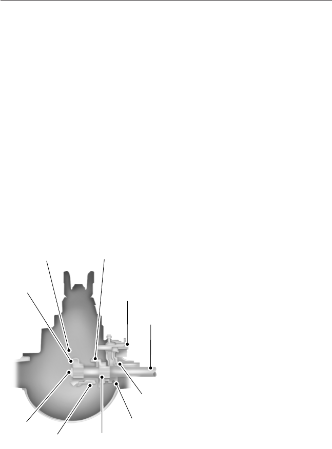
Towing the Vehicle with the Rear Wheels Suspended
Note: To avoid damage to the cab roof or air deflector when towing the
vehicle backward (rear wheels suspended), the air deflector must be
removed.
Whenever possible, it is preferable to tow a disabled vehicle from the
rear by raising the rear of the chassis. When towing a vehicle with the
rear of the chassis suspended, the front wheels must be locked in the
straight-ahead position.
Vehicles equipped with a manual transmission must have at least 1.0 pint
(0.5 liter) of transmission fluid drained from the case. This prevents the
transmission fluid from entering the clutch housing and saturating the
clutch discs. Make sure that the transmission fluid is replaced before the
vehicle is returned to service.
Towing Vehicles Equipped with a Driver-controlled Differential
Lock
Note: If the vehicle must be towed to a service facility with the drive
axle wheels on the ground, it is necessary to remove the axle shafts
before the vehicle is towed.
A. Side gear
B. Differential (plain) case half
C. Shift collar in the locked position
D. Actuator assembly and shift fork
E. Axle shaft
F. Interference between the shift
collar and housing
G. Shift collar in the unlocked
position
H. Outer splines: axle shaft to collar
I. Shift collar and differential case
splines
J. Inner splines: axle shaft to side
gear
E
D
C
B
A
J
I H
G
F
180 Towing
2013 F-650/750 (f67)
Owners Guide gf, 2nd Printing, March 2013
USA (fus)

Removing Axle Shafts before Towing
1. Shift the main differential to the unlocked (disengaged) position; the
differential lock light turns off.
2. Remove the capscrews and washers or stud nuts and washers from
flanges of both axle shafts.
3. Loosen the tapered dowels in the flanges of both axle shafts by
holding a 1
1
⁄
2
inch diameter brass drift or hammer against the axle
shaft center and hitting it with a five or six pound hammer. Note: Do
not use a chisel or wedge to loosen the axle shafts and dowels. Use
of a chisel or wedge can damage the hub, axle shafts and oil seals.
4. Remove the tapered dowels and both axle shafts from the axle
assembly.
5. Assemble a cover over openings of both wheel ends to prevent loss of
lubricant and keep dirt away from the wheel bearing cavities.
Note: One of the axle shafts has two sets of splines. One set to engage
with the differential side gear and one set to engage with the shift collar
for the differential lock. It may be necessary to rotate the shaft slightly
to align the gear spline teeth with the shift collar teeth in order to
remove the axle shaft.
Installing the Axle Shafts
1. Remove the covers from the wheel ends.
2. Shift the differential lock to the unlocked (disengaged) position.
3. Install the axle shafts.
•Place the gaskets on the wheel hub studs.
•Push the right-hand axle shaft and gasket into the wheel end and
housing until the shaft stops against the differential shift collar.
•Push down and in on the axle shaft flange and rotate the shaft
until the splines of the shaft and shift collar are engaged.
•Push the axle shaft further into the housing until the shaft stops
against the differential side gear.
•Push down on the axle shaft flange and rotate the shaft until the
splines of the shaft and side gear are engaged.
•Push the axle shaft completely into the housing until the axle
shaft flange and the gasket are flush against the wheel hub.
•Install the left-hand axle shaft and gasket into the wheel end.
4. If tapered dowels are required, install them at each stud and into the
flange of the axle shaft. Use a punch or drift and hammer, if needed.
5. Install the fasteners and tighten to correct torque value. See the
Workshop Manual.
Towing 181
2013 F-650/750 (f67)
Owners Guide gf, 2nd Printing, March 2013
USA (fus)

BREAKING-IN
You need to break in new tires for approximately 300 miles
(480 kilometers). During this time, your vehicle may exhibit some unique
driving characteristics. Avoid driving too fast during the first 1000 miles
(1600 kilometers). Vary your speed frequently and change up through
the gears early. Do not labor the engine.
ECONOMICAL DRIVING
Fuel economy is affected by several things such as how you drive, the
conditions you drive under and how you maintain your vehicle.
There are some things to keep in mind that may improve your fuel
economy:
•Accelerate and slow down in a smooth, moderate fashion.
•Drive at steady speeds without stopping.
•Anticipate stops; slowing down may eliminate the need to stop.
•Close the windows for high-speed driving.
•Drive at reasonable speeds (traveling at 55 mph [88 km/h] uses 15%
less fuel than traveling at 65 mph [105 km/h]).
•Keep the tires properly inflated and use only the recommended size.
•Use the recommended engine oil.
•Perform all regularly scheduled maintenance.
There are also some things you may not want to do because they may
reduce your fuel economy:
•Sudden or hard accelerations.
•Warm up your vehicle on cold mornings.
•Use the air conditioner or front defroster.
•Use the speed control in hilly terrain.
•Rest your foot on the brake pedal while driving.
•Carry unnecessary weight (approximately 1 mpg [0.4 km/L] is lost for
every 400 pounds [180 kilograms] of weight carried).
•Add particular accessories to your vehicle (e.g., bug deflectors,
rollbars and light bars, running boards, ski racks).
•Drive with the wheels out of alignment.
182 Driving Hints
2013 F-650/750 (f67)
Owners Guide gf, 2nd Printing, March 2013
USA (fus)

DRIVING THROUGH WATER
If driving through deep or standing water is unavoidable, proceed very
slowly especially if the depth is not known. Never drive through water
that is higher than the bottom of the hubs. Traction or brake capability
may be limited and your vehicle may stall. Water may also enter your
engine’s air intake and severely damage your engine, drive axles or the
transmission (through the breather ports).
Once through the water, always dry the brakes by moving your vehicle
slowly while applying light pressure on the brake pedal. Wet brakes do
not stop the vehicle as quickly as dry brakes.
Driving Hints 183
2013 F-650/750 (f67)
Owners Guide gf, 2nd Printing, March 2013
USA (fus)

ROADSIDE ASSISTANCE
Vehicles Sold in the U.S.: Getting Roadside Assistance
To fully assist you should you have a vehicle concern, Ford Motor
Company offers a complimentary roadside assistance program. This
program is separate from the New Vehicle Limited Warranty and is not
applicable to vehicles sold in Canada. The services are available:
•24-hours, seven days a week
•for the New Vehicle Limited Warranty period (U.S.) of two years
(unlimited miles).
Roadside assistance covers:
•battery jump start
•lock-out assistance (Key replacement cost is the customer’s
responsibility.)
•towing – Ford eligible vehicles towed to an authorized dealer within
35 miles (56 kilometers) of the disablement location or to the nearest
authorized dealer. If a member requests to be towed to an authorized
dealer more than 35 miles (56 kilometers) from the disablement
location, the member shall be responsible for any mileage costs in
excess of 35 miles (56 kilometers).
Trailers shall be covered up to $200 if the disabled eligible vehicle
requires service at the nearest authorized dealer. If the trailer is disabled,
but the towing vehicle is operational, the trailer does not qualify for any
roadside services.
Vehicles Sold in the U.S.: Using Roadside Assistance
Complete the roadside assistance identification card and place it in your
wallet for quick reference. This card is found in the owner’s information
portfolio in the glove compartment.
U.S. Ford vehicle customers who require Roadside Assistance, call
1-800-241-3673.
If you need to arrange roadside assistance for yourself, Ford Motor
Company reimburses a reasonable amount for towing to the nearest
dealership within 35 miles (56 kilometers). To obtain reimbursement
information, U.S. Ford vehicle customers call 1-800-241-3673. Customers
are asked to submit their original receipts.
184 Roadside Emergencies
2013 F-650/750 (f67)
Owners Guide gf, 2nd Printing, March 2013
USA (fus)
Vehicles Sold in Canada: Getting Roadside Assistance
Canadian customers who require roadside assistance, call:
1–800–665–2006.
Vehicles Sold Canada: Using Roadside Assistance
Complete the roadside assistance identification card and place it in your
wallet for quick reference. In Canada, the card is found in the warranty
information in the glove box.
Canadian Roadside coverage and benefits may differ from the U.S.
coverage. Please see your warranty information or visit our website at
www.ford.ca for information on Canadian services and benefits.
Canadian customers who need to obtain roadside information, call
1-800-665-2006 or visit our website at www.ford.ca.
HAZARD FLASHER CONTROL
Note: With extended use, the flasher may run down your battery.
The hazard flasher is located on the
steering column, just behind the
steering wheel. The hazard flashers
will operate when the ignition is in
any position or if the key is not in the
ignition.
•Press the flasher control and all
front and rear direction signals
flash.
•Press the flasher control again to
turn them off.
Use it when your vehicle is disabled and is creating a safety hazard for
other motorists.
JUMP-STARTING THE VEHICLE
WARNING: The gases around the battery can explode if exposed
to flames, sparks, or lit cigarettes. An explosion could result in
injury or vehicle damage.
WARNING: Batteries contain sulfuric acid which can burn skin,
eyes and clothing, if contacted.
Roadside Emergencies 185
2013 F-650/750 (f67)
Owners Guide gf, 2nd Printing, March 2013
USA (fus)

Do not attempt to push-start your automatic transmission vehicle.
Automatic transmissions do not have push-start capability. Attempting to
push-start a vehicle with an automatic transmission may cause
transmission damage.
Six-speed TorqShift® transmissions have an adaptive shift strategy.
When the battery is disconnected or a new battery is installed, the
automatic transmission must relearn its shift strategy. As a result, the
transmission may have firm soft shifts, firm shifts or both. This operation
is considered normal and does not affect function or durability of the
transmission. Over time, the adaptive learning process fully updates
transmission operation.
Preparing Your Vehicle
Note: Use only a 12–volt supply to start your vehicle.
Note: Do not disconnect the battery of the disabled vehicle as this could
damage the vehicle’s electrical system.
1. Park the booster vehicle close to the hood of the disabled vehicle
making sure the two vehicles do not touch. Set the parking brake on
both vehicles and stay clear of the engine cooling fan and other
moving parts.
2. Check all battery terminals and remove any excessive corrosion
before you attach the battery cables. Make sure that vent caps are
tight and level.
3. Turn the heater fan on in both vehicles to protect from any electrical
surges. Turn all other accessories off.
Connecting the Jumper Cables
WARNING: Do not connect the end of the second cable to the
negative (-) terminal of the battery to be jumped. A spark may
cause an explosion of the gases that surround the battery.
Note: Do not attach the negative (-) cable to fuel lines, engine rocker
covers, the intake manifold or electrical components as grounding points.
Note: In the illustration, the vehicle on the bottom is used to designate
the assisting (boosting) battery.
186 Roadside Emergencies
2013 F-650/750 (f67)
Owners Guide gf, 2nd Printing, March 2013
USA (fus)
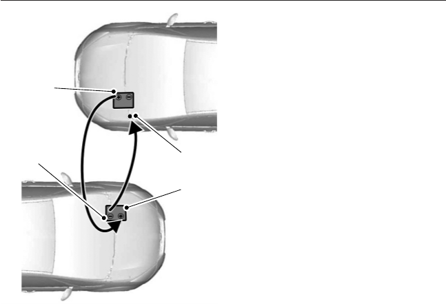
1. Connect the positive (+) jumper
cable to the positive (+)
terminal of the discharged
battery.
2. Connect the other end of the
positive (+) cable to the positive
(+) terminal of the assisting
battery.
3. Connect the negative (-) cable
to the negative (-) terminal of
the assisting battery.
4. Make the final connection of the
negative (-) cable to an exposed
metal part of the stalled
vehicle’s engine, away from the
battery and the carburetor or
fuel injection system.
Make sure that the cables are clear of fan blades, belts, moving parts of
both engines, or any fuel delivery system parts.
Jump Starting
1. Start the engine of the booster vehicle and run the engine at
moderately increased speed.
2. Start the engine of the disabled vehicle.
3. Once the disabled vehicle has been started, run both engines for an
additional three minutes before disconnecting the jumper cables.
Removing the Jumper Cables
Note: In the illustration, the vehicle on the bottom is used to designate
the assisting (boosting) battery.
Remove the jumper cables in the reverse order that they were
connected.
4
2
1
3
Roadside Emergencies 187
2013 F-650/750 (f67)
Owners Guide gf, 2nd Printing, March 2013
USA (fus)
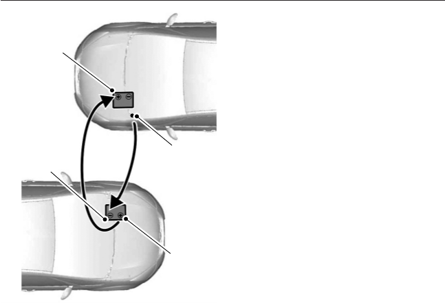
1. Remove the jumper cable from
the ground metal surface.
2. Remove the jumper cable on the
negative (-) terminal of the
booster vehicle’s battery.
3. Remove the jumper cable from
the positive (+) terminal of the
booster vehicle’s battery.
4. Remove the jumper cable from
the positive (+) terminal of the
disabled vehicle’s battery.
After the disabled vehicle has been started and the jumper cables
removed, allow it to idle for several minutes so the engine computer can
relearn its idle conditions.
4
1
3
2
188 Roadside Emergencies
2013 F-650/750 (f67)
Owners Guide gf, 2nd Printing, March 2013
USA (fus)

GETTING THE SERVICES YOU NEED
Warranty repairs to your vehicle must be performed by an authorized
Ford dealer. While any authorized dealer handling your vehicle line will
provide warranty service, we recommend that you return to your
authorized selling dealer to ensure your continued satisfaction.
Please note that certain warranty repairs require special training or
equipment, so not all authorized dealers are authorized to perform all
warranty repairs. This means that, depending on the warranty repair
needed, you may need to take your vehicle to another authorized dealer.
If you have questions or concerns, or are unsatisfied with the service you
are receiving, follow these steps:
1. Contact your Sales Representative or Service Advisor at your selling
or servicing dealership.
2. If your inquiry or concern remains unresolved, contact the Sales
Manager or Service Manager at the dealership.
3. If the inquiry or concern cannot be resolved at the dealership level,
contact the Ford Commercial Vehicle Operations Hotline. Please have
the following information available:
•Vehicle Identification Number (VIN)
•your telephone number (home and business)
•the name of the authorized dealer and city where located
•the vehicle’s current odometer reading.
In some states, you must directly notify Ford in writing before pursuing
remedies under your state’s warranty laws. Ford is also allowed a final
repair attempt in some states.
In the United States:
Mailing address
Ford Motor Company
Commercial Vehicle Operations
PO Box 6248
Dearborn, MI 48121
Telephone
800-782-8627 (option #3)
(TDD for the hearing impaired: 1-800-232-5952)
Online
Additional information and resources are available online at
www.fleet.ford.com:
•U.S. dealer locator by Dealer Name, City/State, or Zip Code
•Owner Guides
•Maintenance Schedules
Customer Assistance 189
2013 F-650/750 (f67)
Owners Guide gf, 2nd Printing, March 2013
USA (fus)

•Recalls
•Ford Extended Service Plans
•Ford Genuine Accessories.
In Canada:
Mailing address
Customer Relationship Centre
Ford Motor Company of Canada, Limited
P.O. Box 2000
Oakville, Ontario L6J 5E4
Telephone
800-565-3673 (FORD)
Online
www.ford.ca
IN CALIFORNIA (U.S. ONLY)
California Civil Code Section 1793.2(d) requires that, if a manufacturer or
its representative is unable to repair a motor vehicle to conform to the
vehicle’s applicable express warranty after a reasonable number of
attempts, the manufacturer shall be required to either replace the vehicle
with one substantially identical or repurchase the vehicle and reimburse
the buyer in an amount equal to the actual price paid or payable by the
consumer (less a reasonable allowance for consumer use). The consumer
has the right to choose whether to receive a refund or replacement vehicle.
California Civil Code Section 1793.22(b) presumes that the manufacturer
has had a reasonable number of attempts to conform the vehicle to its
applicable express warranties if, within the first 18 months of ownership
of a new vehicle or the first 18000 miles (29000 kilometers), whichever
occurs first:
1. Two or more repair attempts are made on the same nonconformity
likely to cause death or serious bodily injury OR
2. Four or more repair attempts are made on the same nonconformity
(a defect or condition that substantially impairs the use, value or
safety of the vehicle) OR
3. The vehicle is out of service for repair of nonconformities for a total
of more than 30 calendar days (not necessarily all at one time).
In the case of 1 or 2 above, the consumer must also notify the
manufacturer of the need for the repair of the nonconformity at the
following address:
Ford Motor Company
16800 Executive Plaza Drive
Mail Drop 3NE-B
Dearborn, MI 48126
190 Customer Assistance
2013 F-650/750 (f67)
Owners Guide gf, 2nd Printing, March 2013
USA (fus)

UTILIZING THE MEDIATION/ARBITRATION PROGRAM
(CANADA ONLY)
For vehicles delivered to authorized Canadian dealers. In those cases
where you continue to feel that the efforts by Ford of Canada and the
authorized dealer to resolve a factory-related vehicle service concern
have been unsatisfactory, Ford of Canada participates in an impartial
third party mediation/arbitration program administered by the Canadian
Motor Vehicle Arbitration Plan (CAMVAP).
The CAMVAP program is a straightforward and relatively speedy
alternative to resolve a disagreement when all other efforts to produce a
settlement have failed. This procedure is without cost to you and is
designed to eliminate the need for lengthy and expensive legal
proceedings.
In the CAMVAP program, impartial third-party arbitrators conduct
hearings at mutually convenient times and places in an informal
environment. These impartial arbitrators review the positions of the
parties, make decisions and, when appropriate, render awards to resolve
disputes. CAMVAP decisions are fast, fair, and final as the arbitrator’s
award is binding on both you and Ford of Canada.
CAMVAP services are available in all Canadian territories and provinces.
For more information, without charge or obligation, call your CAMVAP
Provincial Administrator directly at 1-800-207-0685 or visit
www.camvap.ca.
GETTING ASSISTANCE OUTSIDE THE U.S AND CANADA
Before exporting your vehicle to a foreign country, contact the
appropriate foreign embassy or consulate. These officials can inform you
of local vehicle registration regulations and where to find diesel fuel.
If you cannot find diesel fuel or can only get fuel with an anti-knock
index lower than is recommended for your vehicle, contact a regional
office or owner relations/customer relationship office.
The use of low quality diesel fuel may affect your emissions control
system and may cause engine damage. Ford Motor Company/Ford of
Canada is not responsible for any damage caused by use of improper
fuel. In the United States, using leaded fuel may also result in difficulty
importing your vehicle back into the U.S.
Customer Assistance 191
2013 F-650/750 (f67)
Owners Guide gf, 2nd Printing, March 2013
USA (fus)

Ford dealerships outside of the U.S. and Canada may be unable to
support the F–650/750 due to the specialized training and servicing
requirements of these vehicles. If your vehicle must be serviced while
you are traveling or living in Central or South America, the Caribbean, or
the Middle East, contact the nearest Ford dealership. If the dealership
cannot help you, write or call:
FORD MOTOR COMPANY
FORD EXPORT OPERATIONS
1555 Fairlane Drive
Fairlane Business Park #3
Allen Park, Michigan 48101
U.S.A.
Telephone: (313) 594-4857
FAX: (313) 390-0804
If you are in another foreign country, contact the nearest Ford
dealership. If the dealership employees cannot help you, they can direct
you to the nearest Ford affiliate office.
If you buy your vehicle in North America and then relocate outside of
the U.S. or Canada, register your vehicle identification number (VIN) and
new address with Ford Motor Company Export Operations.
ORDERING ADDITIONAL OWNER’S LITERATURE
To order the publications in this portfolio, contact Helm, Incorporated at:
HELM, INCORPORATED
47911 Halyard Drive
Plymouth, Michigan 48170
Attention: Customer Service
Or to order a free publication catalog, call toll free: 1-800-782-4356
Monday-Friday 8:00 a.m. - 6:00 p.m. EST
Helm, Incorporated can also be reached by their website:
www.helminc.com.
(Items in this catalog may be purchased by credit card, check or
money order.)
Obtaining a French Owner’s Manual
A French owner’s manual can be obtained from your authorized dealer or
by contacting Helm, Incorporated using the contact information listed
previously in this section.
192 Customer Assistance
2013 F-650/750 (f67)
Owners Guide gf, 2nd Printing, March 2013
USA (fus)

REPORTING SAFETY DEFECTS (U.S. ONLY)
If you believe that your vehicle has
a defect which could cause a crash
or could cause injury or death, you
should immediately inform the
National Highway Traffic Safety
Administration (NHTSA) in addition to notifying Ford Motor Company.
If NHTSA receives similar complaints, it may open an investigation, and
if it finds that a safety defect exists in a group of vehicles, it may order a
recall and remedy campaign. However, NHTSA cannot become involved
in individual problems between you, your dealer, or Ford Motor
Company.
To contact NHTSA, you may call the Vehicle Safety Hotline toll-free at
1–888–327–4236 (TTY: 1–800–424–9153); go to http://www.safercar.gov;
or write to:
Administrator
1200 New Jersey Avenue, Southeast
Washington, D.C. 20590
You can also obtain other information about motor vehicle safety from
http://www.safercar.gov.
REPORTING SAFETY DEFECTS (CANADA ONLY)
If you believe that your vehicle has a defect which could cause a crash or
could cause injury or death, you should immediately inform Transport
Canada, using their toll-free number: 1–800–333–0510, or online at:
https://wwwapps.tc.gc.ca/Saf-Sec-Sur/7/PCDB-BDPP/Index.aspx.
Customer Assistance 193
2013 F-650/750 (f67)
Owners Guide gf, 2nd Printing, March 2013
USA (fus)

CHANGING A FUSE
Fuses
WARNING: Always replace a fuse with one that has the
specified amperage rating. Using a fuse with a higher amperage
rating can cause severe wire damage and could start a fire.
If electrical components in your
vehicle are not working, a fuse may
have blown. Blown fuses are
identified by a broken wire within
the fuse. Check the appropriate
fuses before replacing any electrical
components.
Standard Fuse Amperage Rating and Color
COLOR
Fuse
rating
Mini
fuses
Standard
fuses
Maxi
fuses
Cartridge
maxi
fuses
Fuse link
cartridge
2A Grey Grey — — —
3A Violet Violet — — —
4A Pink Pink — — —
5A Tan Tan — — —
7.5A Brown Brown — — —
10A Red Red — — —
15A Blue Blue — — —
20A Yellow Yellow Yellow Blue Blue
25A Natural Natural — Natural Natural
30A Green Green Green Pink Pink
40A — — Orange Green Green
50A — — Red Red Red
60A — — Blue Yellow Yellow
70A — — Tan — Brown
80A — — Natural Black Black
15
194 Fuses
2013 F-650/750 (f67)
Owners Guide gf, 2nd Printing, March 2013
USA (fus)
FUSE SPECIFICATION CHART
Power Distribution Box
WARNING: Always disconnect the battery before servicing high
current fuses.
WARNING: To reduce risk of electrical shock, always replace the
cover to the power distribution box before reconnecting the
battery or refilling fluid reservoirs.
The power distribution box has high-current fuses that protect your
vehicle’s main electrical systems from overloads.
If the battery has been disconnected and reconnected, see Changing the
vehicle battery in the Maintenance chapter.
503
502 304
204
602
118 114 110 106 102
117 113 109 105
116 112 108 104
115 111 107 103
101
601
209
208
206
205
207
203
202
201
303
501
401
302 301
18161412108642
1715131197531
24
23
22 20
21 19
Fuses 195
2013 F-650/750 (f67)
Owners Guide gf, 2nd Printing, March 2013
USA (fus)

Fuse/Relay
Location
Fuse Amp
Rating Protected Circuits
1 20A Upfitter switches (AUX 2 and AUX 4)/Trailer
12V socket pin
2 30A Power seat (driver)
3 30A Power seat (passenger)
4 15A Windshield washer relay, Washer pump motor
5 5A Brake warning switch (hydraulic brake
vehicles only)
6 20A Upfitter switches (AUX 1 and AUX 3)
7 15A Brake pressure switches, ABS event relay
8 20A DEF (Urea) line heaters (diesel engine only)
9 20A Ignition switch, Starter cutoff
10 15A Air tank moisture removal valve
11 30A Electric trailer brake
12 20A Passenger compartment fuse box 5 and 21
13 15A Instrument cluster/Gateway module
14 20A Nitrogen oxide sensor (diesel engine only)
15 — Not used
16 5A Bendix® Air ABS
17 — Not used
18 10A Fuel transfer pump
19 15A Powertrain control module power 1 (gasoline
engine only)
20 10A Powertrain control module power 2 (gasoline
engine only)
21 20A Powertrain control module power 3 (gasoline
engine only)
22 20A Powertrain control module power 4 (gasoline
engine only)
23 — Not used
24 10A Powertrain control module keep-alive power
(gasoline engine only)
196 Fuses
2013 F-650/750 (f67)
Owners Guide gf, 2nd Printing, March 2013
USA (fus)

Fuse/Relay
Location
Fuse Amp
Rating Protected Circuits
101 30A Bendix Air ABS relay (Air brake vehicles
only)
Hydraulic brakes module (hydraulic brake
vehicles only)
102 20A Ignition switch
103 20A Ignition switch, Passenger compartment fuse
box fuses 19, 29 and 30
104 20A Power point
105 20A Power door lock switches
106 30A Main light switch, Multi-function switch
107 50A Passenger compartment fuse box fuses 1, 2,
3, 4, 12, 13, 14 and 15
108 40A Fuel heater (diesel engine only)
20A Fuel pump module (gasoline engine only)
109 40A Power window
110 30A Windshield wiper
111 30A Body builder relay, Parking lamps
112 40A Blower motor
113 30A Heated seats, Air-Ride seat
114 20A Aftertreatment DCU
115 20A Ignition switch, Passenger compartment fuse
box fuses 8, 9, 10 and 11
116 30A Left/Right turn relays, Back up lamp relay
117 20A Stop lamps
118 60A Hydraulic brake vehicles (trailer tow package
only)
601 60A Trailer socket
602 60A Air brake trailer tow fuse block
30A Hydraulic brakes pump motor 2
201 — Windshield washer relay
202 — Wiper high/low relay
203 — Wiper run/park relay
Fuses 197
2013 F-650/750 (f67)
Owners Guide gf, 2nd Printing, March 2013
USA (fus)
Fuse/Relay
Location
Fuse Amp
Rating Protected Circuits
204 — Windshield wiper relay
205 — Body builder relay, right turn
206 — Body builder relay, left turn
207 — ABS event relay (hydraulic brake vehicles
only)
208 — Body builder relay, back up lamps relay
209 — Auxiliary stop lamp relay
301 — Fuel heater/Fuel transfer pump relay (diesel
engine only)
— Fuel pump module (gasoline engine only)
302 — Body builder relay, parking lamps relay
303 — Blower motor relay
304 — DEF (Urea) line heaters relay (diesel engine
only)
— Powertrain control module power VPWR1
(gasoline engine only)
Individual Maxi Fuse Holder in Engine Compartment
Fuse/Relay
Location
Fuse Amp
Rating Protected Circuits
9925 30A Hydraulic brakes pump motor 1
198 Fuses
2013 F-650/750 (f67)
Owners Guide gf, 2nd Printing, March 2013
USA (fus)
Passenger Compartment Fuse Panel
The fuse box is located behind the passenger airbag cover and can be
accessed through the glove box.
Fuse/Relay
Location
Fuse Amp
Rating Protected Circuits
1 20A Horn
2 15A Flasher relay
3 20A Power point
4 10A Data Link Connector (DLC), Engine
diagnostic connector, Parking brake warning
5 15A Run relay
6 — Not used
7 — Not used
8 5A Radio, GEM
9 5A Power window relay
10 15A Heated mirrors
11 5A Wiper and washer systems
12 10A Transmission shift selector
13 20A Radio/SYNC®, Power mirrors
14 10A Interior lamp relay
15 10A Interior lamp relay
Relay #2
Relay #3
Horn
Relay #4
Relay #5
#1 #12 #22
#2 #13 #23
#3 #14 #24
#4 #15 #25
#6 #17 #27
#5 #16 #26
#7 #18 #28
#8 #19 #29
#9 #30
#10 #20
#11 #21 #31
Relay #1
Fuses 199
2013 F-650/750 (f67)
Owners Guide gf, 2nd Printing, March 2013
USA (fus)

Fuse/Relay
Location
Fuse Amp
Rating Protected Circuits
16 15A High beams, Indicator
17 — Not used
18 5A Dimmer switch, Interior lighting
19 15A Engine control (diesel engine only)
20 5A Starting system
21 10A DRL resistor
22 15A Air horn, Air suspension dump, Two-speed
axle, Driver-controlled locking differential
23 10A Flasher relay
24 15A Hydraulic brakes relay, Fuel heater relay
(diesel engine only), Air dryer
25 10A Blower motor relay coil
26 10A Right-hand low beam headlight
27 — Not used
28 10A Left-hand low beam headlight
29 10A Cluster, GEM
30 15A Allison electronic transmission
31 15A Mirror fold relay
Relay 1 — Interior lamps
Relay 2 — Not used
Relay 3 — Horn
Relay 4 — Not used
Relay 5 — Not used
200 Fuses
2013 F-650/750 (f67)
Owners Guide gf, 2nd Printing, March 2013
USA (fus)

Relay Center
The relay center is located along the passenger side A-pillar on the right
side of the footwell.
Relay
Location
Relay Description
R1 Spring applied hydraulic release warning chime module or
PCM power VPWR 2, 3 and 4
R2 A/C compressor clutch
R3 Power windows
R4 Flasher (standard/LED)
R5 Upfitter relay 1
R6 Upfitter relay 2
R7 Headlights
R8 Spare
R9 Upfitter relay 3
R10 Starter
R11 DCU (diesel engine only)
R12 Two–speed axle/Differential lock
R13 Door lock
R14 Air tank moisture valve
R15 DRL #1
R16 Heated mirrors
R17 Spare
R18 Upfitter relay 4
R1
R9 R10 R11 R12 R13 R14 R15 R16 R17
R18 R19 R20 R21 R22 R23 R24 R25 R26
R2 R3 R4 R5 R6 R7 R8
Fuses 201
2013 F-650/750 (f67)
Owners Guide gf, 2nd Printing, March 2013
USA (fus)
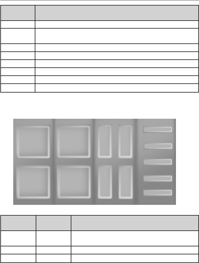
Relay
Location
Relay Description
R19 Shift interlock/EPRNDL display
R20 Selective Catalyst Reduction (SCR) system (NOx) (diesel
engine only)
R21 Run
R22 Door unlock
R23 ABS warning indicator
R24 DRL #2
R25 Park lights
R26 Spare
Trailer Tow Relays (If Equipped)
Fuse/Relay
Location
Fuse Amp
Rating
Protected Circuits
1 30A* Trailer tow ABS feed (non electric trailer
brake vehicles only)
2 30A* Trailer tow park/marker lamps
3 30A* Trailer tow stop lamps
TRAILER
ABS
TRAILER
STOP
LAMP
TRAILER
MARKER
LAMP
TRAILER
TAIL
LAMP
NOT
USED
NOT
USED
LH
TURN
RH
TURN
30A
30A
30A
30A
NOT USED
5
4
3
2
1
R1 R2 R5 R6
R3 R4 R7 R8
202 Fuses
2013 F-650/750 (f67)
Owners Guide gf, 2nd Printing, March 2013
USA (fus)

Fuse/Relay
Location
Fuse Amp
Rating
Protected Circuits
4 30A* Trailer tow turn/stop lamps (combined)
Trailer tow turn lamps (separate)
5 — Not used
R1 — Trailer tow ABS relay (non electric trailer
brake vehicles only)
R2 — Trailer tow marker lamp relay
R3 — Trailer tow stop lamp relay
R4 — Trailer tow tail lamp relay
R5 — Not used
R6 — Not used
R7 — Trailer tow left turn lamp relay
R8 — Trailer tow right turn lamp relay
*Maxi fuse
Inline Fuses
Your vehicle may have several inline fuses located in, or on, the battery
cables located in the battery box (depending on application).
•All vehicles equipped with an Allison transmission have a 10 amp fuse
located in the clean power cables located in the battery box.
•All vehicles have a 30 amp fuse located in the clean power cables
located in the battery box.
•All vehicles equipped with an Eaton transmission have a 30 amp fuse
located in the clean power cables located in the battery box.
•All vehicles equipped with hydraulic brakes have a 40 amp fuse
located in the clean power cables located in the battery box. In
addition, another 30 amp fuse is located in a fuse holder just above
the power distribution center located in the vehicle’s engine
compartment.
Fuses 203
2013 F-650/750 (f67)
Owners Guide gf, 2nd Printing, March 2013
USA (fus)

GENERAL INFORMATION
WARNING: Making modifications to various parts, components
and systems of the vehicle, such as brake and steering systems,
can adversely affect the quality, reliability and operation of your vehicle
and could result in property damage, personal injury or death. Such
modifications must be avoided.
WARNING: Failure to properly perform maintenance and
servicing procedures could result in vehicle damage, personal
injury or death.
WARNING: Take care when performing any maintenance,
system check or service on your vehicle. Some of the materials
may also be hazardous if used, serviced or handled improperly and
could result in property damage, personal injury or death.
Always use care when performing vehicle maintenance, repairs or system
checks. Improper or incomplete service could result in the vehicle not
working properly which may result in personal injury or damage to the
vehicle or equipment. It is the operator’s responsibility to see that the
vehicle receives proper care and maintenance. If you have any questions
about performing service, have the service done by a qualified technician.
Servicing Guidelines
When servicing your vehicle:
•always wear safety glasses for eye protection.
•always set the parking brake or chock the wheels.
•always use support stands, not a jack, when working under a raised
vehicle.
•always turn off the ignition unless a procedure requires the engine to
be running.
•always avoid contact with hot metal parts. Allow the components to
cool before working with, or around, them.
•always operate the engine in a well-ventilated area.
•do not wear loose-fitting clothing, hanging jewelry, watches or rings.
•do not smoke.
•do not work on the brakes or the clutch unless the proper
precautions are taken to avoid inhaling friction material dust.
Quality service parts are available through your dealer. If dealer parts are
not used, make sure the replacement parts are of equivalent quality.
204 Maintenance
2013 F-650/750 (f67)
Owners Guide gf, 2nd Printing, March 2013
USA (fus)

WARNING: The use of inferior parts can adversely affect the
quality and reliability of your vehicle which, in turn, can result in
property damage, personal injury or death.
To avoid damage to the vehicle’s electrical components prior to electric
welding:
•disconnect both battery cables.
•attach the welder ground cable as close as possible to the part being
welded.
•it is recommended that the component be temporarily removed if
welding close to an electrical component.
Follow the checks and services in the Scheduled Maintenance chapter.
Have your dealer or service center inspect your vehicle at least once a
year. Remember that regular maintenance and inspections usually
prevent serious problems from developing later.
If the owner or operator of the vehicle is a skilled technician and intends
on performing the vehicle maintenance and service, he is strongly urged
to purchase a service manual.
Electrical System
Periodically inspect electrical connectors on the outside of the cab and
on the engine and frame for corrosion and tightness. Exposed terminals,
such as the fuel sender, cranking motor, alternator and feed-through
studs, should be cleaned and re-coated with a lubricant sealing grease
such as Motorcraft® Silicone Brake Caliper Grease and Dielectic
Compound XG-3, or equivalent. This should include the ground cable
connector for batteries, engine and cab as well as the jump starting stud.
Accessory Feed Connections
Vehicle electrical systems are complex and often include powertrain
components, such as engine and transmission controls, instrument
panels, ABS, etc. While most systems operate on battery voltage
(12 volts), some systems can be as high as 90 volts or as low as five
volts. See the Electrical Circuit Diagram Manuals, available from your
vehicle’s manufacturer, to make sure that any additional body lights and
accessories are connected to circuits that are both appropriate and not
overloaded. No modification should be made to any vehicle control
system without first contacting your dealer.
Maintenance 205
2013 F-650/750 (f67)
Owners Guide gf, 2nd Printing, March 2013
USA (fus)

Climate Control System
Have the air conditioning system checked each spring. The refrigerant
charge, cleanliness of the condenser-evaporator cores and belt condition
are essential to system performance.
When the air conditioning system is being used daily, remove the fresh
air filter (if equipped) once each season and check for dirt, lint, etc.
Replace the filter if necessary. Vehicles operating in unusually dusty
conditions may require more frequent filter inspection and replacement.
Front Axle
Maintaining the front axle alignment to specifications is very important
and should only be performed by a qualified technician. Regular
inspections should include:
•toe-in inspection and adjustment (if necessary), particularly with
radial tires.
•checking for proper tightness of axle mounting U-bolt nuts, attaching
or mounting bolts and nuts.
•checking the axle for damage, binding, worn parts and adequate
lubrication..
•checking the kingpins for excessive wear. This should also be done
during other scheduled maintenance (tire rotation or service, wheel
bearing service, alignment, etc.). See the workshop manual for proper
procedures.
Toe-in
It is essential that correct toe-in and tire pressure be maintained for
optimum tire wear.
Inspecting steer axle tires in the first 3000–10000 service miles
(5000–16000 service kilometers) generally shows if tires are wearing
normally.
Rapid outside shoulder wear on both tires indicates too much toe-in.
Rapid inside shoulder wear on both tires indicates too much toe-out.
In P&D-type service, left-to-right steer tire tread life differentials up to
40% can be observed depending on routes and other variables.
Follow the tire manufacturer’s recommended cold inflation pressure for
the tire size, load range (ply rating) and steer axle loading typical for
their operation (each steer axle tire equals
1
⁄
2
steer axle loading).
206 Maintenance
2013 F-650/750 (f67)
Owners Guide gf, 2nd Printing, March 2013
USA (fus)

Special applications may warrant a setting based on experience with the
type of tire operating loads and conditions. Radial tires are more
sensitive to toe-in setting than bias ply tires. While not insensitive to
vehicle alignment, fine tuning school bus alignment to line-haul truck
standards does not drastically improve tire tread life.
Rear Axle
Regular inspections should include:
•checking for proper tightness of axle mounting U-bolt nuts, attaching
or mounting bolts and nuts. See Spring U-bolt checks later in this
chapter.
•checking the axle for damage, binding, worn parts and adequate
lubrication.
NoSpin Detroit Locker Positive Locking Differential
Vehicles equipped with this type differential have the operator’s manual
supplied with the vehicle. See that manual for maintenance inspections.
Maintenance 207
2013 F-650/750 (f67)
Owners Guide gf, 2nd Printing, March 2013
USA (fus)

Brake System
Note: Persons handling brake linings should follow all precautions listed
below:
WARNING:
1. Always wear a respirator approved by the National Institute of
Occupational Studies of Health (NIOSH) or Mine Safety and Appliance
(MSA) during all brake service procedures. Wear the respirator from
removal of the wheels through assembly.
2. Never use compressed air or dry brushing to clean brake parts or
assemblies.
3. Clean brake parts and assemblies in open air. During assembly,
carefully place all parts on the floor to avoid getting dust in the air. Use
an industrial vacuum cleaner with a HEPA filter system to clean dust
from the brake drums, backing plates and other brake parts. After using
the vacuum, remove any remaining dust with a rag soaked in water and
wrung until nearly dry.
4. Never use compressed air or dry sweeping to clean the work area.
Use an industrial vacuum cleaner with a HEPA filter system and rags
soaked in water and wrung until nearly dry. Dispose of used rags with
care to avoid getting dust in the air. Use an approved respirator when
emptying vacuum cleaners and handling used rags.
5. Worker clean-up: Wash your hands before eating, drinking or
smoking. Vacuum your work clothes after use and then launder them
separately, without shaking them, to prevent fiber dust getting into the
air.
Your vehicle is equipped with non-asbestos brake linings. However,
exposure to excessive amounts of brake material (whether asbestos or
non-asbestos, fiberglass, mineral wool, aramid or carbon) may be a
serious health hazard.
208 Maintenance
2013 F-650/750 (f67)
Owners Guide gf, 2nd Printing, March 2013
USA (fus)

Air Brakes
WARNING: Do not manually adjust the automatic slack adjusters
to correct excessive push rod stroke as it may result in reduced
brake effectiveness and a vehicle crash. Excessive push rod stroke
indicates that a problem exists with the automatic adjuster, with the
installation of the adjuster, or with foundation brake components that
manual adjustment does not remedy. Seek service from a qualified
facility for excessive push rod stroke.
Inspection and adjustment: Establish a regular schedule for periodic
cleaning, lubrication and adjustment inspection based on vehicle use.
Exact maintenance intervals are difficult to predetermine since vehicles
are used in a wide variety of applications and conditions. If you are
uncertain of the proper schedule for your vehicle, contact your dealer.
Regular inspections should include:
•periodic checking (every service interval) of push rod travel or brake
adjustment. This is essential for effective braking. Brake chamber
push rods on original equipment chambers now incorporate an orange
paint marker near the base of the push rod as a stroke indicator to
aid in adjustment checks. If the push rod is clean and the brakes are
out of adjustment, the orange marker can be seen protruding from
the chamber when the brakes are applied.
•checking the brake lining (every service interval). When brake lining
or blocks are worn to within 1/16th inch (1.6 millimeters) of rivets,
replace the brake linings. This inspection or adjustment should only
be performed by a qualified technician and must be in accordance
with instructions provided by the service manual.
Do not back off or disconnect the front brakes so that they are less
effective, letting the rear brakes do all the stopping of the vehicle. Do
not overlook the brakes on the trailer either. Brake condition on the
trailer is just as important as the tractor. Proper brake balance on trucks
and tractor-trailers is essential for effective braking.
Once a year, the entire brake system must be inspected:
•Rubber components for deterioration. These components should be
inspected by a qualified technician and replaced as necessary.
Replacement intervals vary according to the severity and length of
vehicle service.
•Condition of brake drums, brake chambers and slack adjusters.
•System for air leaks.
•Hose or pipes for rust, damage and deterioration.
•Operation of service and parking brakes.
Maintenance 209
2013 F-650/750 (f67)
Owners Guide gf, 2nd Printing, March 2013
USA (fus)
Some parts such as air brake chamber diaphragm, air compressor and air
cleaner should be inspected periodically and replaced if considered
unserviceable.
Air dryer: Climactic conditions affect performance of desiccant or
after-cooler type air dryers. Maintenance schedules must be established
for each specific operation.
The use of an air dryer on a vehicle does not eliminate the need to
periodically drain the air reservoirs.
Desiccant air dryer: Inspect for moisture in the air system by opening
reservoirs, draincocks or valves and checking for presence of water. The
presence of small amounts of water due to condensation is normal and
should not be considered as an indication that the dryer is not
functioning properly.
The desiccant cartridge should be replaced or rebuilt when it has been
determined that the desiccant is contaminated and does not have
adequate water absorption capacity. The desiccant change interval may
vary. It is generally recommended that the desiccant be replaced every
12 months (yearly). If experience has shown that extended or shortened
life has resulted for a particular installation, then the yearly interval can
be increased or decreased accordingly.
Draining the air brake reservoir:
Completely drain all the air brake
reservoirs daily by opening the
draincock at the ends of the tanks
(Where accessible. Pull-chains are
used when the drains are undercab
or otherwise inaccessible). Close the
draincock after draining. Air tanks
equipped with automatic moisture
ejector valves may also be drained
manually as required to maintain a
dry air system. Contact your dealer if you are unsure of the air reservoir
locations or the draining procedure.
WARNING: Failure to drain air brake reservoirs can result in a
reduction or loss of braking ability due to fluid accumulation in
the reservoir and/or possible freeze-up during cold weather.
210 Maintenance
2013 F-650/750 (f67)
Owners Guide gf, 2nd Printing, March 2013
USA (fus)

Hydraulic Brakes
Establish a regular schedule for periodic cleaning, lubrication and
adjustment inspection based on vehicle use. Exact maintenance intervals
are difficult to predetermine since vehicles are used in a wide variety of
applications and conditions. If you are uncertain of the proper schedule
for your vehicle, contact your dealer.
Regular inspections should include:
•checking the brake lining (every service interval). Establish
inspection intervals that provide for lining replacement before damage
to the disc occurs. Excessive lining wear may expose the backing
plate to the disc causing scoring of the disc faces. This inspection
should be performed by a qualified technician and must be in
accordance with instructions provided by the service manual.
Hydraulic brake systems are power-assisted. Braking capabilities are
greatly reduced without engine assist.
•proper fluid level. The level should be at the bottom edge of the ring
on each reservoir fill port. Do not fill the master cylinder to the top of
the reservoir. If fluid level requires attention to maintain a proper
master cylinder level, this is an indication of either severe operation
(pad wear) or fluid leakage. A more frequent and thorough brake
inspection is required.
•brake lines, hoses and fittings. Repair or replace brake line tubes,
hoses or fittings as required. Inspect these components every
4000 miles (6000 kilometers):
•Lines for kinks, dents, corrosion or rupture.
•Hoses for abrasions, kinks, soft spots or rupture, collapse, cracks,
twists or loose frame supports. When replacing a hose, be sure
there is adequate clearance to the hose to avoid an abrasion to the
new hose.
•All connections for leaks.
Driveline Parking Brake
WARNING: Use wheel chocks and exercise caution when
inspecting under the vehicle. A vehicle roll-away could result in
property damage, personal injury or death.
Parking brake adjustment should only be performed by a qualified
technician, and in accordance with the instructions in the service
manual.
Maintenance 211
2013 F-650/750 (f67)
Owners Guide gf, 2nd Printing, March 2013
USA (fus)

Steering System
WARNING: Failure to maintain the steering system in proper
condition can cause reduced steering ability resulting in property
damage, personal injury or death.
Note: Have any steering problems immediately corrected by a qualified
service technician.
Ask your service technician to examine the steering mechanism. Only
minor adjustments may be necessary. Regular inspections should include:
•checking the tie rod, drag link end clamp bolts and ball joints for
proper tightness.
•checking for installation and spread of cotter pins and tightness of
nuts at both ends of the tie rod and drag link.
•checking that the pitman arm (steering arm at steering gear)
mounting is tight and locked. Check system for leaks or hose chafing.
Repair immediately, if necessary.
•maintaining proper steering gear and power steering pump lubricant
levels.
•checking steering column joint bolts and steering linkage, particularly
for body-to-chassis clearance.
Steering Column Joint Bolts
As a good maintenance practice, it is recommended that steering column
joint bolts be checked for tightness every 60000 miles (96000 kilometers)
or annually, whichever occurs first. DO NOT OVERTIGHTEN.
Hydraulic System
Whenever the power steering’s hydraulic system has been drained and
refilled for any reason, air must be bled from the system before returning
the vehicle to service. Failure to properly bleed the hydraulic system can
result in degradation of power system performance.
Consult your dealer who is aware of the proper procedures for filling and
bleeding the system.
212 Maintenance
2013 F-650/750 (f67)
Owners Guide gf, 2nd Printing, March 2013
USA (fus)

Catalytic Converter (Diesel Engine)
Note: If your vehicle is equipped with a catalytic converter/muffler, do
not blend waste oil with diesel fuel. Operate only on ultra low sulfur
(less than 15 parts per million sulfur) diesel fuel with a cetane value of
45 or higher.
If your diesel engine is equipped with a catalytic converter, it is
important to review the maintenance schedule to make sure proper
functioning of the catalytic converter. Also, take precautions not to
damage the catalytic converter when servicing your engine or storing
your vehicle.
Diesel Exhaust Fluid (DEF), Diesel Particulate Filter (DPF) and
Select Catalyst Reduction (SCR) System
See your engine operator’s manual for information regarding DEF, DPF
and SCR system service.
Air Induction System
WARNING: When performing maintenance to any turbocharged
engine with engine air inlet piping disconnected, keep loose
clothing, jewelry and long hair away from the engine air inlet piping.
A turbocharger compressor air inlet protective shield should be
installed over the turbocharger air inlet to reduce the risk of personal
injury or death.
Perform a complete inspection of the air induction system annually.
In areas where road salt is used, disassemble the joints of each aluminum
component and inspect for salt build-up and presence of chlorine that
can cause aluminum particles to flake off and enter the engine
combustion chambers. If evidence of corrosion is found (usually at the
pipe connections), use a wire brush to clean the inside of the pipes and
inside the rubber hoses.
If the intake pipes are pitted at the joint ends, use Motorcraft® Silicone
Gasket and Sealant TA-30 to seal the joints. Make sure no excess
material is on the inside of the pipes that can be pulled into the engine.
If the service condition of the pipes, hoses or clamps is questionable,
replace the defective part(s).
Make sure all dust and debris has been cleaned out of the pipes and
couplings with a clean, damp rag prior to reassembly.
Maintenance 213
2013 F-650/750 (f67)
Owners Guide gf, 2nd Printing, March 2013
USA (fus)

Chassis-mounted Charge Air Cooler
Visually inspect the core assembly for debris and clogging of external fins
with the engine off. Prior to engine operation, remove any debris
blocking the core.
•Turbocharger-to-charge air cooler
•Charge air cooler-to-intake manifold pipe
•Mounting bracket
•Chassis-mounted charge air cooler core
Inspect air intake piping:
•Check for accumulation of salt deposits (where applicable).
If present, disassemble and clean the complete air intake piping
system. If the intake piping is pitted, use Motorcraft® Silicone Gasket
and Sealant TA-30 to seal joints against leakage.
•Check for loose hoses and clamps.
•Check for ruptured or collapsed hoses.
•Check air cleaner housing for cracks.
Suspension Inspection
Note: Do not adjust air suspension height to any setting other than the
specified setting. Altering the height setting changes the driveline angle
and may result in unwarrantable component damage, such as
transmission component damage.
Verify drive axle air suspension height and height control valve
performance at engine oil change intervals.
Periodically check:
•Condition of spring leaves for evidence of fatigue, bending or
breakage.
•Condition of suspension mounting brackets and bushings.
•Torque rod mounting fasteners for tightness.
•For proper suspension alignment. This must be maintained at all
times.
•U-bolts. After the chassis has been operating under load for
1000 miles (1600 kilometers) or six months (whichever comes first),
the U-bolt nuts must be re-torqued. The U-bolt nuts must be
re-torqued every 36000 miles (60000 kilometers) thereafter. The
U-bolt and nut threads and seats should be cleaned and lubricated to
make sure a like new condition when re-torquing.
Note: See Spring U-bolt check later in this chapter.
214 Maintenance
2013 F-650/750 (f67)
Owners Guide gf, 2nd Printing, March 2013
USA (fus)
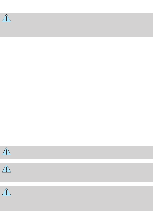
Supporting Your Vehicle for Service
WARNING: Do not use a jack when working under a vehicle. It
may give way, causing the vehicle to fall and result in property
damage, personal injury or death. Always use floor stands to support
the vehicle.
Prepare the vehicle for service repairs by doing the following:
1. Park the vehicle on a level, concrete floor.
2. Set the parking brake and block the wheels to prevent the vehicle
from moving.
3. Select a jack with a rated capacity sufficient to lift and hold up the
vehicle.
4. Raise the vehicle with the jack applied to the axle(s). DO NOT use
the bumper as a lifting point.
5. Support the vehicle with floor stands under the axle(s). If the axle or
the suspension is being serviced, support the vehicle with floor
stands under the frame side-members, preferably between the axles.
Frame and Tow Hooks
Your vehicle’s chassis is manufactured with frame rails of either HSLA
steel or heat-treated steel. Each must be handled in a specific manner to
make sure maximum service life. Consult the service manual or your
dealer before attempting frame repair or modification.
It is important, particularly on vehicles where the tow hooks are used
frequently, to inspect the front and rear tow hooks for damage or a loose
mounting.
OPENING AND CLOSING THE HOOD
WARNING: The parking brake must be fully set before opening
the hood or possible personal injury may occur.
WARNING: To reduce the risk of the possibility of personal
injury, never stand beneath the hood when it is being raised or
lowered.
WARNING: If you must leave the engine running while checking
under the hood, do not allow any loose clothing, jewelry, hair or
other items to get near moving engine components or possible personal
injury may occur.
Maintenance 215
2013 F-650/750 (f67)
Owners Guide gf, 2nd Printing, March 2013
USA (fus)
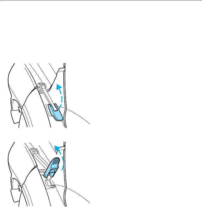
The hood and fenders are held in position by a latch located on each
fender.
Before opening the hood, set the parking brake, shift into position N
(automatic transmission) or first (manual transmission) and turn the
engine off.
To open the hood:
1. Lift up on the bottom of each latch.
2. Pull the bottom of each latch away from the fender.
216 Maintenance
2013 F-650/750 (f67)
Owners Guide gf, 2nd Printing, March 2013
USA (fus)
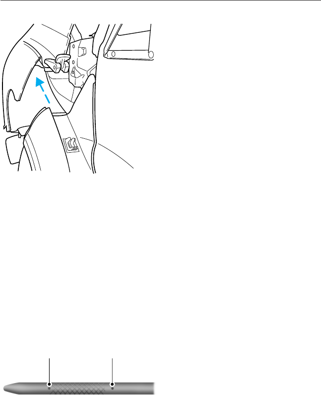
3. Tilt the hood forward until stopped by the retaining cables.
To lower the hood:
1. Push the hood rearward at the top center of the hood above the
grille until closed.
2. Engage the latch on each fender.
3. Push down on the bottom of each latch until locked.
ENGINE OIL DIPSTICK
Diesel Engine
See your engine operator’s manual for information on the engine oil
dipstick.
Gasoline Engine
A. MIN
B. MAX
A B
Maintenance 217
2013 F-650/750 (f67)
Owners Guide gf, 2nd Printing, March 2013
USA (fus)

ENGINE OIL CHECK
Diesel Engine
See your engine operator’s manual for information on checking and
adding engine oil as well as engine oil specifications, capacities and
required maintenance.
Gasoline Engine
Checking the Engine Oil
1. Make sure the vehicle is on level ground.
2. Turn the engine off and wait 15 minutes for the oil to drain into the
oil pan.
3. Set the parking brake and make sure the gearshift is securely latched
in position P.
4. Open the hood. Protect yourself from engine heat.
5. Locate and carefully remove the engine oil level dipstick.
6. Wipe the dipstick clean. Insert the dipstick fully, then remove it
again.
•If the oil level is between the lower and upper holes, the oil level
is acceptable. DO NOT ADD OIL.
•If the oil level is below the lower hole, add enough oil to raise the
level within the lower and upper holes.
•Oil levels above the upper hole may cause engine damage. Some
oil must be removed from the engine by an authorized dealer.
7. Put the dipstick back in and make sure it is fully seated.
Adding Engine Oil
Note: Do not remove the engine oil level dipstick or the filler cap when
the engine is running.
Note: Do not add engine oil further than the MAX mark. Oil levels above
the MAX mark may cause engine damage.
Only use oils certified for gasoline engines by the
American Petroleum Institute (API). An oil with this
trademark symbol conforms to the current engine and
emission system protection standards and fuel
economy requirements of the International Lubricants
Specification Advisory Council (ILSAC), comprised of
U.S. and Japanese automobile manufacturers.
1. Check the engine oil level.
218 Maintenance
2013 F-650/750 (f67)
Owners Guide gf, 2nd Printing, March 2013
USA (fus)

2. If the engine oil level is not within the normal range, add engine oil
that meets Ford specifications. See Capacities and Specifications
for more information. Remove the engine oil filler cap and use a
funnel to pour the engine oil into the opening.
3. Recheck the engine oil level. Make sure the oil level is not above the
normal operating range on the engine oil level dipstick.
4. Install the dipstick and make sure it is fully seated.
5. Fully install the engine oil filler cap by turning the filler cap
clockwise until three clicks are heard or until the cap is fully seated.
ENGINE COOLANT CHECK
Diesel Engine
See your engine operator’s manual for information on checking and
adding engine coolant.
Fan Clutches
WARNING: Stay clear of the fan and fan area while the engine is
running or possible personal injury may occur.
Your vehicle’s cooling system is equipped with a viscous fan clutch
which:
•Helps control cooling, increases performance, improves fuel economy
and reduces noise.
•Is controlled by bimetallic spring sensors. Do not tamper with these
sensors as this may change their calibration or keep the fan clutch
from operating at all.
Gasoline Engine
Checking the Engine Coolant
The concentration and level of engine coolant should be checked at the
intervals listed in the Scheduled Maintenance chapter.
Note: Make sure that the level is between the MIN and MAX marks on
the coolant reservoir.
Note: Coolant expands when it is hot. The level may extend beyond the
MAX mark.
If the level is at the MIN mark, add coolant immediately. See Adding
engine coolant in this section.
Maintenance 219
2013 F-650/750 (f67)
Owners Guide gf, 2nd Printing, March 2013
USA (fus)

Note: For best results, coolant concentration should be tested with a
refractometer such as Rotunda tool 300-ROB75240E available from your
dealer. Ford does not recommend the use of hydrometers or coolant test
strips for measuring coolant concentrations.
Note: Automotive fluids are not interchangeable; do not use engine
coolant, antifreeze or windshield washer fluid outside of its specified
function and vehicle location.
Adding Engine Coolant
WARNING: Do not add engine coolant when the engine is hot.
Steam and scalding liquids released from a hot cooling system
can burn you badly. Also, you can be burned if you spill coolant on hot
engine parts.
WARNING: Do not put engine coolant in the windshield washer
fluid container. If sprayed on the windshield, engine coolant
could make it difficult to see through the windshield.
WARNING: To reduce the risk of personal injury, make sure the
engine is cool before unscrewing the coolant pressure relief cap.
The cooling system is under pressure; steam and hot liquid can come
out forcefully when the cap is loosened slightly.
WARNING: Do not add coolant further than the MAX mark.
Note:
Do not use stop leak pellets or cooling system sealants or additives
as they can cause damage to the engine cooling and heating systems. This
damage would not be covered under your vehicle’s warranty.
Note: During normal vehicle operation, the engine coolant may change
color from orange to pink or light red. As long as the engine coolant is
clear and uncontaminated, this color change does not indicate the engine
coolant has degraded nor does it require the engine coolant to be
drained, the system to be flushed, or the engine coolant to be replaced.
•DO NOT MIX different colors or types of coolant in your vehicle.
Make sure the correct coolant is used. Mixing of engine coolants may
harm your engine’s cooling system. The use of an improper coolant
may harm engine and cooling system components and may void the
warranty.
220 Maintenance
2013 F-650/750 (f67)
Owners Guide gf, 2nd Printing, March 2013
USA (fus)

•
In case of emergency, a large amount of water without engine coolant
may be added in order to reach a vehicle service location. In this
instance, the cooling system must be drained, chemically cleaned with
Motorcraft® Premium Cooling System Flush, and refilled with prediluted
engine coolant as soon as possible. Water alone (without engine coolant)
can cause engine damage from corrosion, overheating or freezing.
•Do not use alcohol, methanol, brine or any engine coolants mixed with
alcohol or methanol antifreeze (coolant). Alcohol and other liquids can
cause engine damage from overheating or freezing.
•Do not add extra inhibitors or additives to the coolant. These can be
harmful and compromise the corrosion protection of the engine coolant.
Unscrew the cap slowly. Any pressure escapes as you unscrew the cap.
Add prediluted engine coolant meeting the Ford specification.
See Capacities and Specifications for more information.
Whenever coolant has been added, the coolant level in the coolant
reservoir should be checked the next few times you drive the vehicle.
If necessary, add enough prediluted engine coolant to bring the coolant
level to the proper level.
Recycled Engine Coolant
Ford Motor Company does not recommend the use of recycled engine
coolant since a Ford-approved recycling process is not yet available.
Always dispose of used automotive fluids in a responsible manner. Follow
your community’s regulations and standards for recycling and disposing
of automotive fluids.
Severe Climates
If you drive in extremely cold climates:
•It may be necessary to have a Ford authorized dealer increase the
coolant concentration above 50%.
•A coolant concentration of 60% provides improved freeze point
protection. Engine coolant concentrations above 60% decrease the
overheat protection characteristics of the engine coolant and may
cause engine damage.
If you drive in extremely hot climates:
•It may be necessary to have a Ford authorized dealer decrease the
coolant concentration to 40%.
•A coolant concentration of 40% provides improved overheat
protection. Engine coolant concentrations below 40% decrease the
corrosion and freeze protection characteristics of the engine coolant
and may cause engine damage.
Maintenance 221
2013 F-650/750 (f67)
Owners Guide gf, 2nd Printing, March 2013
USA (fus)

Vehicles driven year-round in non-extreme climates should use
prediluted engine coolant for optimum cooling system and engine
protection.
What You Should Know About Fail-Safe Cooling (If Equipped)
(Gasoline Engine Only)
WARNING: If fail-safe cooling activates, pull off the road as soon
as safely possible and turn the engine off. The engine may
automatically shut off while driving without further indication.
If the engine coolant supply is depleted, this feature allows the vehicle to
be driven temporarily before incremental component damage is incurred.
The fail-safe distance depends on ambient temperatures, vehicle load and
terrain.
How Fail-Safe Cooling Works
If the engine begins to overheat:
•The engine coolant temperature gauge moves to the red (hot) area.
•The information display indicates the engine is overheating.
•The service engine soon indicator illuminates.
If the engine reaches a preset over-temperature condition, the engine
automatically switches to alternating cylinder operation. Each disabled
cylinder acts as an air pump and cools the engine.
When Fail-Safe Mode Is Activated
WARNING: Never remove the coolant reservoir cap while the
engine is running or hot.
Note: Driving the vehicle without repairing the engine problem increases
the chance of engine damage. Take your vehicle to an authorized dealer
as soon as possible.
You have limited engine power when in the fail-safe mode, so drive the
vehicle with caution. The vehicle is not able to maintain high-speed
operation and the engine runs rough. Remember that the engine is
capable of completely shutting down automatically to prevent engine
damage; therefore:
1. Pull off the road as soon as safely possible and turn off the engine.
2. Arrange for the vehicle to be taken to an authorized dealer.
3. If this is not possible, wait a short period for the engine to cool.
4. Check the coolant level and replenish if low.
5. Restart the engine and take your vehicle to an authorized dealer.
222 Maintenance
2013 F-650/750 (f67)
Owners Guide gf, 2nd Printing, March 2013
USA (fus)

TRANSMISSION FLUID CHECK
Allison Automatic Transmissions
See your Allison Automatic Transmission Operator’s Manual for
scheduled transmission fluid checks and change intervals. Your
transmission does not consume fluid. However, the fluid level should be
checked if the transmission is not working properly, i.e., if the
transmission slips or shifts slowly or if you notice some sign of fluid
leakage.
Automatic transmission fluid expands when warmed. To obtain an
accurate fluid check, drive the vehicle until it is at normal operating
temperature (approximately 20 miles [30 kilometers]). Verify that the
transmission fluid temperature gauge, located on the instrument cluster,
is within the normal range.
1. Drive the vehicle 20 miles (30 kilometers) or until it reaches normal
operating temperature.
2. Park the vehicle on a level surface and engage the parking brake.
3. With the engine running, parking brake engaged and your foot on the
brake pedal, move the gearshift lever through all of the gear ranges.
Allow sufficient time for each gear to engage.
4. Latch the gearshift lever in position Nor Pand leave the engine
running.
5. Remove the dipstick, wiping it clean with a clean, dry, lint-free rag.
6. Install the dipstick making sure it is fully seated in the filler tube.
7. Remove the dipstick and inspect the fluid level. The fluid should be
in the designated area for normal operating temperature or ambient
temperature.
If you must add transmission fluid, see your Allison Automatic
Transmission Operator’s Manual for the correct fluid type. Use of a
non-approved automatic transmission fluid may cause internal
transmission component damage.
Fluid levels above the safe range may result in transmission failure. An
overfill condition of transmission fluid may cause shift or engagement
concerns or possible damage.
TorqShift® Automatic Transmission
See the Scheduled Maintenance chapter for scheduled intervals for
fluid checks and changes. Your transmission does not consume fluid.
However, the fluid level should be checked if the transmission is not
working properly, i.e., if the transmission slips or shifts slowly or if you
notice some sign of fluid leakage.
Maintenance 223
2013 F-650/750 (f67)
Owners Guide gf, 2nd Printing, March 2013
USA (fus)
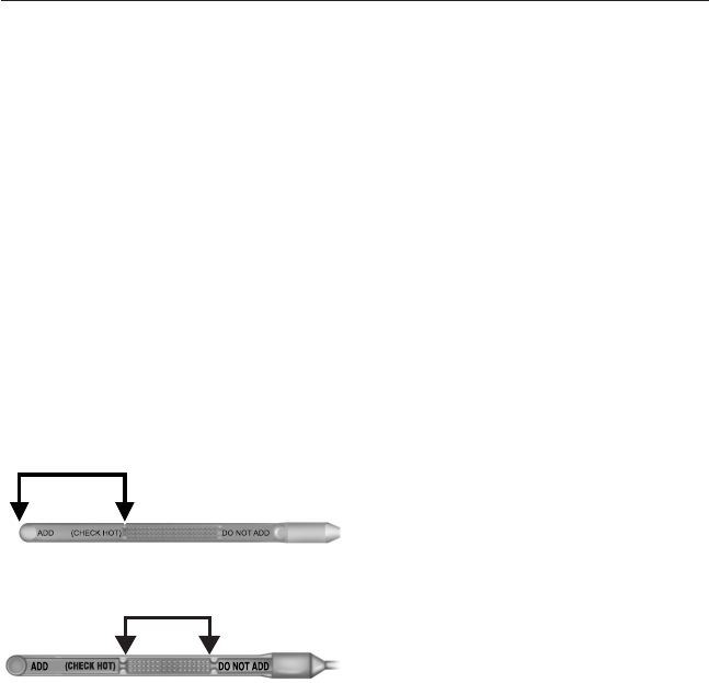
Automatic transmission fluid expands when warmed. To obtain an
accurate fluid check, drive the vehicle until it is at normal operating
temperature (approximately 20 miles [30 kilometers]). Verify that the
transmission fluid temperature gauge, located on the instrument cluster,
is within the normal range.
1. Drive the vehicle 20 miles (30 kilometers) or until it reaches normal
operating temperature.
2. Park the vehicle on a level surface and engage the parking brake.
3. With the engine running, parking brake engaged and your foot on the
brake pedal, move the gearshift lever through all of the gear ranges.
Allow sufficient time for each gear to engage.
4. Latch the gearshift lever in position Pand leave the engine running.
5. Remove the dipstick, wiping it clean with a clean, dry, lint-free rag.
6. Install the dipstick making sure it is fully seated in the filler tube.
7. Remove the dipstick and inspect the fluid level. The fluid should be
in the designated area for normal operating temperature or ambient
temperature.
Low Fluid Level
Do not drive the vehicle if there is
no indication of fluid on the dipstick
and the ambient temperature is
above 50°F (10°C).
Correct Fluid Level
The fluid should be checked at
normal operating temperature
196°F-216°F (91°C-102°C) on a
level surface. The normal operating
temperature can be reached after approximately 20 miles (30 kilometers)
of driving.
224 Maintenance
2013 F-650/750 (f67)
Owners Guide gf, 2nd Printing, March 2013
USA (fus)
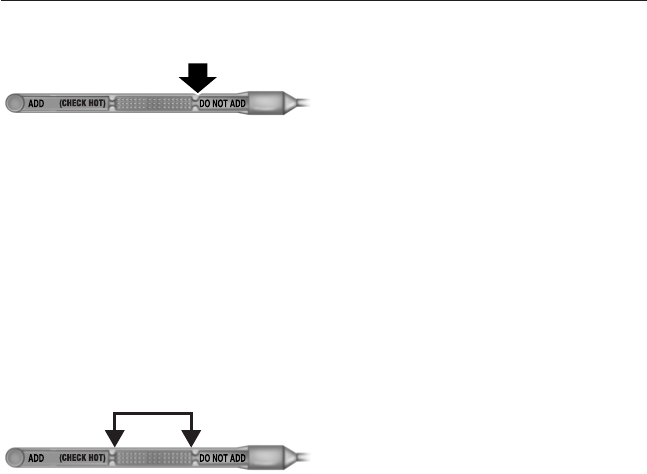
High Fluid Level
Fluid levels above the safe range
may result in transmission failure.
An overfill condition of transmission
fluid may cause shift or engagement
concerns and possible damage.
High fluid levels can be caused by an overheating condition.
Adjusting Automatic Transmission Fluid Levels
Note: Use of a non-approved automatic transmission fluid may cause
internal transmission component damage.
Before adding any fluid, make sure the correct type is used. The type of
fluid used is normally indicated on the dipstick handle and also in the
Capacities and Specifications chapter.
If necessary, add fluid in
1
⁄
2
pint (250 ml) increments through the filler
tube until the level is correct.
If an overfill occurs, excess fluid
should be removed by a qualified
technician.
Note: An overfill condition of transmission fluid may cause shift or
engagement concerns or possible damage.
Do not use supplemental transmission fluid additives, treatments or
cleaning agents. The use of these materials may affect transmission
operation and result in damage to internal transmission components.
Manual Transmissions
Note: Use of a non-approved transmission fluid may cause internal
transmission component damage.
See the Scheduled Maintenance chapter for scheduled intervals for
fluid checks and changes.
Your manual transmission may be filled with an optional synthetic fluid
which allows the use of extended service intervals. A tag on the filler
plug identifies the use of the synthetic fluid.
Only use fluid that meets manufacturer specifications. See Technical
specifications in the Capacities and Specifications chapter.
Maintenance 225
2013 F-650/750 (f67)
Owners Guide gf, 2nd Printing, March 2013
USA (fus)

Checking Fluid Level
1. Park the vehicle on level ground.
2. Set the parking brake, shift into first gear and turn the engine off.
3. Clean any dirt from around the filler plug.
4. Remove the filler plug and inspect the fluid level. The fluid level
should be at the bottom of the filler plug opening.
5. Add fluid, if necessary, through the filler plug opening.
6. Clean and install the filler plug securely.
Changing Fluid
Drain and refill your transmission fluid while it is warm.
1. Park the vehicle on level ground.
2. Set the parking brake, shift into first gear and turn the engine off.
3. Clean any dirt from around the filler and drain plugs.
4. Remove the filler and drain plugs and drain the fluid into a suitable
container. Dispose of all used automotive fluids in a responsible
manner following your local authorized standards.
5. Clean and install the drain plug securely.
6. Add fluid through the filler plug opening.
7. Clean and install the filler plug securely.
DRIVESHAFT
Check the universal joints for any evidence of wear or looseness at the
regular lubrication interval. Stop the vehicle immediately, should
driveshaft vibrations occur, to avoid possible hazardous consequences or
damage to other components.
REAR AXLE FLUID
Your rear axle may be filled with an optional synthetic lubricant which
allows the use of extended service intervals. A tag on the filler plug
identifies the use of the synthetic lubricant.
Only use a lubricant that meets manufacturer specifications. See the
Capacities and Specifications chapter. Use of a non-approved rear
axle lubricant may cause internal axle component damage.
226 Maintenance
2013 F-650/750 (f67)
Owners Guide gf, 2nd Printing, March 2013
USA (fus)

Checking the Fluid Level
See the Scheduled Maintenance chapter for rear axle lubricant level
check intervals.
1. Park the vehicle on level ground.
2. Set the parking brake and shift into position Nor P(automatic
transmission), or first gear (manual transmission). Turn the engine
off.
3. Clean any dirt from around the rear axle filler plug.
4. Remove the filler plug and inspect the lubricant level. It should be at
the bottom of the filler plug opening.
5. Add lubricant, if necessary, through the filler plug opening.
6. Clean and install the filler plug securely.
Changing the Fluid
See the Scheduled Maintenance chapter for rear axle lubricant change
intervals.
1. Drain the rear axle while the lubricant is warm.
2. Park the vehicle on level ground.
3. Set the parking brake and shift into position Nor P(automatic
transmission), or first gear (manual transmission). Turn the engine
off.
4. Clean any dirt from around the rear axle filler and drain plugs.
5. Remove the filler and drain plugs. Drain the lubricant into a suitable
container. Dispose of all used automotive fluids in a responsible
manner following your local authorized standards.
6. Clean and install the drain plug securely.
7. Add lubricant through the filler plug opening.
8. Clean and install the filler plug securely.
Maintenance 227
2013 F-650/750 (f67)
Owners Guide gf, 2nd Printing, March 2013
USA (fus)
SPRING U-BOLT CHECKS
Check U-bolt nuts and re-torque every 36000 miles (60000 kilometers)
after initial 1000 mile (1600 kilometer) re-torque. The U-bolt and nut
threads and seats should be cleaned and lubricated to make sure peak
condition when re-torqued.
U-bolt Nut Torque
Suspension ft-lb N•m
Front axle – 8500 lb (3856 kg) 180-200 244-271
Front axle – 10000 lb (4536 kg) and higher 260-300 353-407
Rear axle with multi-leaf 260-300 353-407
Rear axle with IROS air suspension 370-400 502-542
Rear axle with Hendrickson air suspension 400–450 542–610
See air suspension U-bolt re-torquing and installation information below.
Air Suspension U-bolt Checks and Re-torquing Procedures
1. Inspect the threads of the U-bolt and nut for rust and debris. Clean
the threads if contaminated.
2. Using a torque wrench, determine if any nuts can be turned with a
force below the specified torque.
3. Using the lowest discovered torqued nut as a starting point,
re-tighten the nuts using the sequence listed under Air suspension
U-bolt and U-bolt nut installation.
Air Suspension U-bolt and U-bolt Nut Installation
1. Inspect the threads of the U-bolt and nut for rust and debris. Clean
the threads if contaminated.
2. Install the U-bolts and nuts and torque the nuts to seat the cap flat
which is about 18 ft-lb (25 N•m) using a diagonal pattern. Use the
same diagonal pattern for each of the following U-bolt nut re-torque
steps.
3. Tighten U-bolt nuts in increments of 74 ft-lb (100 N•m) until
tightened to final torque for the particular suspension.
228 Maintenance
2013 F-650/750 (f67)
Owners Guide gf, 2nd Printing, March 2013
USA (fus)
BRAKE FLUID CHECK
WARNING: Brake fluid is toxic. If brake fluid contacts the eyes,
flush eyes with running water for 15 minutes. Seek medical
attention if irritation persists. If taken internally, drink water and induce
vomiting. Seek medical attention immediately.
WARNING: If you use a brake fluid that is not DOT 3, you will
cause permanent damage to your brakes.
WARNING: Do not let the reservoir for the master cylinder run
dry. This may cause the brakes to fail.
Check and refill the Full Power brake fluid reservoir using the following
procedure. See the Scheduled Maintenance chapter for the service
interval.
1. Clean the reservoir caps before removal to prevent dirt or water from
entering the reservoir.
2. Visually inspect the fluid level. It should be at the bottom of the fill
ports.
3. Add brake fluid, if necessary, from a clean, unopened container until
the level reaches the bottom of the fill ports. Do not fill above this
line.
Only use a DOT 3 brake fluid certified to meet manufacturer
specifications. See the Capacities and Specifications chapter.
CLUTCH FLUID AND LINKAGE
Clutch Fluid
WARNING: Carefully read cautionary information on product
label. For MEDICAL EMERGENCY INFORMATION, contact a
physician or Poison Control Center immediately; on Ford-Motorcraft®
products call: 1-800-959-3673 (FORD). Failure to follow these
instructions may result in personal injury.
Use only a DOT 3 brake fluid designed to meet manufacturer
specifications. See the Capacities and Specifications chapter.
During normal operation, the fluid level in the clutch reservoir should
remain constant. If the fluid level drops, fill to the step in the reservoir.
Maintenance 229
2013 F-650/750 (f67)
Owners Guide gf, 2nd Printing, March 2013
USA (fus)
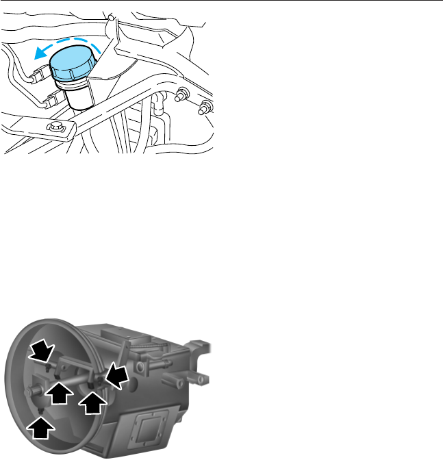
1. Set the parking brake, shift into
first gear and turn the engine
off.
2. Open the hood.
3. Clean the reservoir cap before
removal to prevent dirt and
water from entering the
reservoir.
4. Remove cap and rubber
diaphragm from reservoir.
5. Add fluid, if necessary, until it
reaches the step in the reservoir.
6. Reinstall rubber diaphragm and cap onto reservoir.
See the Scheduled Maintenance chapter for service intervals.
Clutch Linkage
Lubricate the clutch linkage using the following procedure. Use a grease
which meets manufacturer specifications. See the Capacities and
Specifications chapter.
Transmission and clutch removed for clarity.
1. Set the parking brake, shift into
first gear and turn the engine
off.
2. Remove the inspection cover
from the clutch housing.
3. Lubricate the clutch release
bearing (one location) and the
clutch release shaft (two
locations) grease fittings with a
grease gun.
4. Lubricate the clutch release
wear pads (two locations) where
they contact the clutch release
bearing with a brush or similar
tool.
5. Reinstall the inspection cover.
See the Scheduled Maintenance chapter for service intervals.
230 Maintenance
2013 F-650/750 (f67)
Owners Guide gf, 2nd Printing, March 2013
USA (fus)
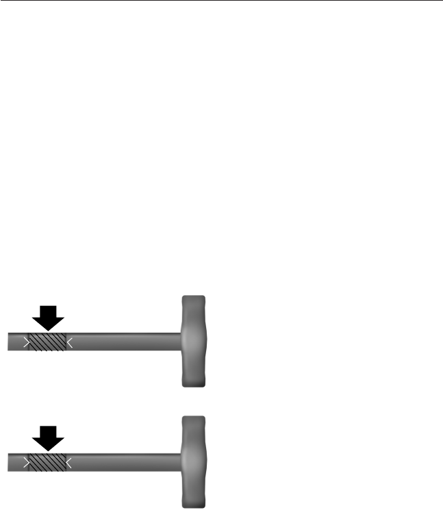
POWER STEERING FLUID CHECK
Note: To avoid damage to the power steering system, do not operate the
vehicle with a low power steering fluid level.
Note: If adding fluid is necessary, use only the appropriate fluid. See the
Capacities and Specifications chapter. A low fluid level may indicate a
leak in the power steering system. Inspect the power steering system
and repair the leak or see your dealer or a qualified technician for
service. See the Scheduled Maintenance chapter for the recommended
service intervals.
Check the fluid level when it is at ambient temperature, 20°F–80°F
(-7°C–25°C):
1. Set the parking brake, then start the engine.
2. Shift into position Nor P(if equipped) (automatic transmission) or
first gear (manual transmission) and turn the engine off.
3. Open the hood.
4. Clean the top of the power steering fluid reservoir.
5. Remove the dipstick from the reservoir and wipe the dipstick clean.
6. Reinstall the dipstick. Remove it again and check the fluid level.
Check the MAX. COLD side of the
dipstick if the fluid is cool or warm to
the touch (approximately 68°F-120°F
[20°C-49°C]). The fluid level should
be within the FULL range. If
necessary, add fluid in small amounts,
continuously checking the level, until
it reaches the proper level.
Check the MAX. HOT side of the
dipstick if the fluid is too hot to
touch (approximately 176°F–230°F
[80°C-110°C]). The fluid level
should be within the FULL range.
If necessary, add fluid in small
amounts, continuously checking the
level, until it reaches the proper
level.
Whenever the dipstick is installed, make sure it is properly seated and
tightened securely.
The fluid level can also be checked by looking at the see-through plastic
reservoir. Make sure that the fluid is within the minimum and maximum
fluid range as marked on the reservoir.
ADD MAX. COLD
FULL
ADD MAX. HOT
FULL
Maintenance 231
2013 F-650/750 (f67)
Owners Guide gf, 2nd Printing, March 2013
USA (fus)

FUEL FILTER
Gasoline Engine
Your vehicle is equipped with a lifetime fuel filter that is integrated with
the fuel tank. Regular maintenance or replacement is not needed.
Diesel Engine
WARNING: Do not drain water separator while engine is
running. Fuel may ignite if separator is drained while engine is
running or vehicle is moving.
The fuel filter/water separator removes any contaminated particles and
water from the fuel before the fuel enters the engine.
See your engine operator’s manual for information on draining and
replacing the fuel filter.
WASHER FLUID CHECK
WARNING: If you operate your vehicle in temperatures below
40°F (5°C), use washer fluid with antifreeze protection. Failure
to use washer fluid with antifreeze protection in cold weather could
result in impaired windshield vision and increase the risk of injury or
accident.
Add fluid to fill the reservoir if the level is low. Only use a washer fluid
that meets Ford specifications. See Technical specifications in the
Capacities and Specifications chapter.
State or local regulations on volatile organic compounds may restrict the
use of methanol, a common windshield washer antifreeze additive.
Washer fluids containing non-methanol antifreeze agents should be used
only if they provide cold weather protection without damaging the
vehicle’s paint finish, wiper blades or washer system.
232 Maintenance
2013 F-650/750 (f67)
Owners Guide gf, 2nd Printing, March 2013
USA (fus)

CHANGING THE VEHICLE BATTERY
WARNING: This vehicle may be equipped with more than one
battery, removal of cable from only one battery does not
disconnect the vehicle electrical system. Be sure to disconnect cables
from all batteries when disconnecting power. Failure to do so may
cause serious personal injury or property damage.
WARNING: Batteries normally produce explosive gases which
can cause personal injury. Therefore, do not allow flames, sparks
or lighted substances to come near the battery. When working near the
battery, always shield your face and protect your eyes. Always provide
proper ventilation.
WARNING: When lifting a plastic-cased battery, excessive
pressure on the end walls could cause acid to flow through the
vent caps, resulting in personal injury and/or damage to the vehicle or
battery. Lift the battery with a battery carrier or with your hands on
opposite corners.
WARNING: Keep batteries out of reach of children. Batteries
contain sulfuric acid. Avoid contact with skin, eyes or clothing.
Shield your eyes when working near the battery to protect against
possible splashing of acid solution. In case of acid contact with skin or
eyes, flush immediately with water for a minimum of 15 minutes and
get prompt medical attention. If acid is swallowed, call a physician
immediately.
WARNING: Battery posts, terminals and related accessories
contain lead and lead compounds. Wash hands after handling.
Note: If your battery has a cover/shield, make sure it is reinstalled after
the battery has been cleaned or replaced.
Note: Electrical or electronic accessories or components added to the
vehicle by the dealer or the owner may adversely affect battery
performance and durability.
Maintenance 233
2013 F-650/750 (f67)
Owners Guide gf, 2nd Printing, March 2013
USA (fus)
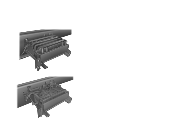
Your vehicle is equipped with two or three maintenance-free batteries
mounted in a covered tray located on the left frame rail. The covered
battery tray, depending upon application, may also have one or two steps
attached.
Covered battery tray shown
(battery tray with steps
similar). The two rubber straps on
top of the cover must be pulled up
and moved to the side of the
battery in order to remove the lid.
Battery tray with cover
removed.
For longer, trouble-free operation,
keep the top of the battery clean
and dry. Also, make certain the
battery cables are always tightly
fastened to the battery terminals.
If you see any corrosion on the battery or terminals, remove the cables
from the terminals and clean with a wire brush. You can neutralize the
acid with a solution of baking soda and water.
It is recommended that the negative battery cable terminal be
disconnected from the battery if you plan to store your vehicle for an
extended period of time. This will minimize the discharge of your battery
during storage.
If the engine cranks but does not start, remove the battery box cover
and check the 40 amp inline fuse located on the battery cable above the
battery.
Because your vehicle’s engine is electronically controlled by a computer,
some control conditions are maintained by power from the battery. When
the battery is disconnected or a new battery is installed, the engine must
relearn its idle and fuel trim strategy for optimum driveability and
performance. To begin this process:
1. With the vehicle at a complete stop, set the parking brake.
2. Put the gearshift in position P(automatic transmission) or neutral
(manual transmission), turn off all accessories and start the engine.
3. Run the engine until it reaches normal operating temperature.
4. Allow the engine to idle for at least one minute.
5. Turn the A/C on and allow the engine to idle for at least one minute.
234 Maintenance
2013 F-650/750 (f67)
Owners Guide gf, 2nd Printing, March 2013
USA (fus)

6. Release the parking brake. With your foot on the brake pedal and
with the A/C on, put the vehicle in position P(automatic
transmission) or neutral (manual transmission) and allow the engine
to idle for at least one minute. Note: If you do not allow the engine
to relearn its idle trim, the idle quality of your vehicle may be
adversely affected until the idle trim is eventually relearned.
7. Drive the vehicle to complete the relearning process.
If the battery has been disconnected or a new battery has been installed,
the clock and radio settings must be reset once the battery is
reconnected.
Always dispose of automotive
batteries in a responsible manner.
Follow your local authorized
standards for disposal. Call your
local authorized recycling center to
find out more about recycling
automotive batteries.
CHECKING THE WIPER BLADES
Run the tip of your fingers over the edge of the blade
to check for roughness.
Clean the wiper blades with washer fluid or water
applied with a soft sponge or cloth.
LEAD
RETURN
RECYCLE
Maintenance 235
2013 F-650/750 (f67)
Owners Guide gf, 2nd Printing, March 2013
USA (fus)
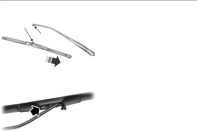
CHANGING THE WIPER BLADES
1. To remove the wiper blade, pull
the wiper arm away from the
vehicle. Pry open the lock cover
(A) with your thumb to release
the blade.
2. Press the retaining clip to
disengage the wiper blade, then
pull the wiper blade down (C)
toward the windshield to remove
it from the arm.
3. To install the new wiper blade,
insert the wiper blade into the
wiper arm hook (B).
4. While holding the wiper arm,
push the wiper blade up and
away from the windshield.
5. Close the lock cover.
Replace wiper blades at least once per year for optimum performance.
Poor wiper quality can be improved by cleaning the wiper blades and the
windshield. See Cleaning the windows and wiper blades in the Vehicle
Care chapter.
To prolong the life of the wiper blades, it is highly recommended to
scrape off the ice on the windshield before turning on the wipers. The
layer of ice has many sharp edges and can damage the micro edge of the
wiper rubber element.
AIR FILTER CHECK
Diesel Engine
See your engine operator’s manual for information on the engine air
filter.
Gasoline Engine
Note: Do not start your engine with the air cleaner removed and do not
remove it while the engine is running.
A
B
C
236 Maintenance
2013 F-650/750 (f67)
Owners Guide gf, 2nd Printing, March 2013
USA (fus)
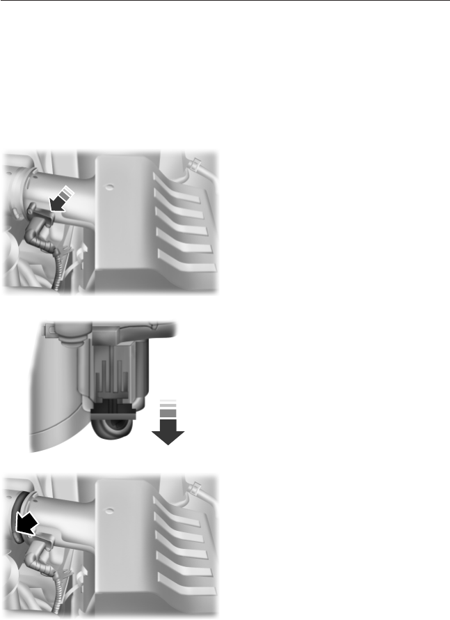
Note: Failure to use the correct air filter element may result in severe
engine damage. The customer warranty may be void for any damage to
the engine if the correct air filter element is not used.
See the Scheduled Maintenance chapter for the appropriate intervals
for changing the air filter element.
When changing the air filter element, use only the Motorcraft® air filter
element listed. See Motorcraft® part numbers in the Capacities and
Spcificationschapter.
1. Locate and disconnect the mass
air flow sensor electrical connector
on the air outlet tube.
2. Reposition the locking clip on the
connector (connector shown from
below for clarity). Squeeze the
connector and pull it off of the air
outlet tube.
3. Clean the area around the air
tube-to-air cover connection to
prevent debris from entering the
system. Loosen the bolt on the air
tube clamp so the clamp is no
longer snug to the air tube. It is not
necessary to completely remove the
clamp.
4. Pull the air tube off the air
cleaner housing.
Maintenance 237
2013 F-650/750 (f67)
Owners Guide gf, 2nd Printing, March 2013
USA (fus)
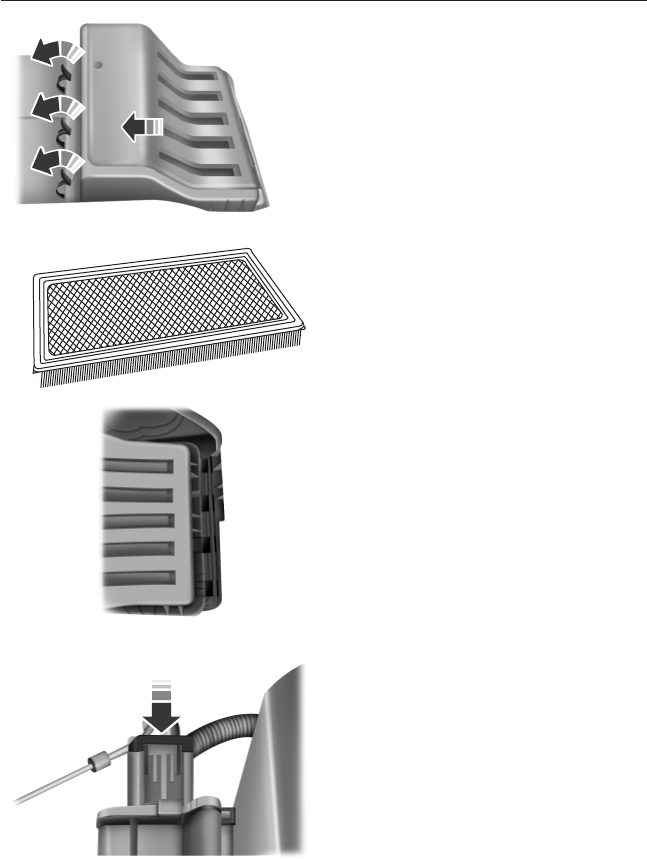
5. Release the three clamps that secure
the cover to the air filter housing. Push
the air filter cover toward the center of
the vehicle, and up slightly, to release it.
6. Remove the air filter element
from the air filter housing.
7. Install a new air filter element.
8. Replace the air filter housing
cover and secure the clamps.
Be careful not to crimp the filter
element edges between the air filter
housing and cover and make sure
that the tabs on the edge are
properly aligned into the slots.
9. Slip the air tube onto the air
filter housing and tighten the air
tube clamp bolt snugly. Do not
overtighten the clamp.
10. Connect the mass air flow
sensor electrical connector to the
outlet tube. Make sure the locking
tab on the connector is in the
locked position (connector shown
from below for clarity).
238 Maintenance
2013 F-650/750 (f67)
Owners Guide gf, 2nd Printing, March 2013
USA (fus)
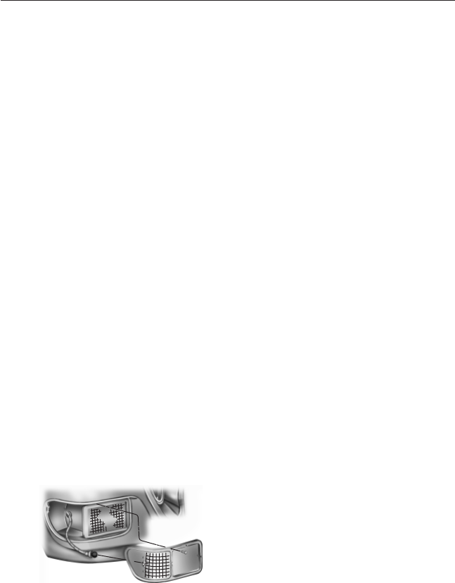
ADJUSTING THE HEADLAMPS
The headlamps on your vehicle are properly aimed at the assembly plant.
If your vehicle has been in an accident, the alignment of your headlamps
should be checked by your authorized dealer.
CHANGING A BULB
Lamp Assembly Condensation
Exterior lamps are vented to accommodate normal changes in pressure.
Condensation can be a natural by-product of this design. When moist air
enters the lamp assembly through the vents, there is a possibility that
condensation can occur when the temperature is cold. When normal
condensation occurs, a thin film of mist can form on the interior of the
lens. The thin mist eventually clears and exits through the vents during
normal operation. Clearing time may take as long as 48 hours under dry
weather conditions.
Examples of acceptable condensation are:
•Presence of thin mist (no streaks, drip marks or droplets).
•Fine mist covers less than 50% of the lens.
Examples of unacceptable moisture (usually caused by a lamp water
leak) are:
•Water puddle inside the lamp.
•Large water droplets, drip marks or streaks present on the interior of
the lens.
Take your vehicle to a dealer for service if any of the above conditions of
unacceptable moisture are present.
Replacing Headlamp Bulbs
1. Make sure the headlamp control is in the off position.
2. Remove the four screws, then
move the parking lamp assembly
away from the headlamp bulb.
Maintenance 239
2013 F-650/750 (f67)
Owners Guide gf, 2nd Printing, March 2013
USA (fus)
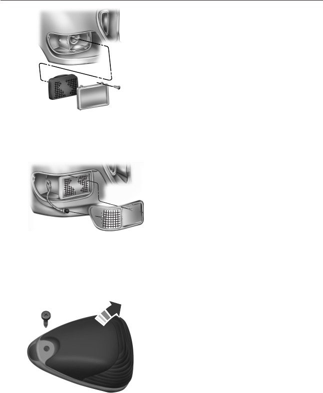
3. Remove the four screws and the
retaining bracket from the headlamp
bulb.
4. Pull the headlamp bulb out of the
housing. Disconnect the electrical
connector, then remove the
headlamp bulb.
5. Reverse the procedure to install
the new bulb.
Replacing Front Parking/Turn Signal/Side Marker Lamp Bulbs
To remove the parking lamp/turn signal bulbs:
1. Make sure the headlamp control
is in the off position and the
turn signals are off.
2. Remove the four screws from
the lamp assembly.
3. Carefully lower the lamp
assembly and pull the bulb
socket straight out of the lamp
assembly.
4. Carefully pull the bulb straight out of the socket.
5. Reverse the procedure to install the new bulb.
Replacing Front Clearance and Identification Lamp Bulbs
1. Make sure the headlamp control
is in the off position.
2. Remove the screw and lens from
the lamp assembly.
3. Pull the bulb straight out of the
socket.
4. Reverse the procedure to install
the new bulb.
240 Maintenance
2013 F-650/750 (f67)
Owners Guide gf, 2nd Printing, March 2013
USA (fus)
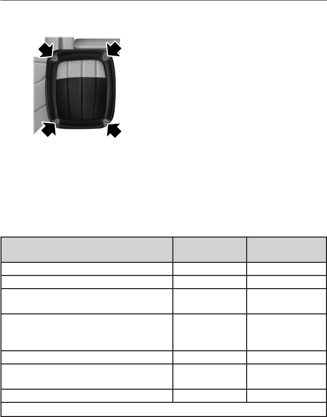
Replacing Brake/Tail/Rear Turn Signal/Reverse/License Plate Lamp
Bulbs
1. Remove the four screws and the
lamp lens from the lamp
assembly.
2. Carefully pull the bulb straight
out of the socket.
3. Reverse the procedure to install
the new bulb.
BULB SPECIFICATION CHART
Replacement bulbs are specified in the chart below. Headlamp bulbs
must be marked with an authorized D.O.T. for North America and an E
for Europe to make sure lamp performance, light brightness and pattern
and safe visibility. The correct bulbs will not damage the lamp assembly
or void the lamp assembly warranty and will provide quality bulb
illumination time.
Function Number of
Bulbs
Trade Number
Headlamps 2 H6054
Front turn signal lamps 2 1157
Front sidemarker lamps, parking
lamps
2 (amber) 194
Brake lamps, tail lamps, stop lamps,
rear turn signals lamps, license plate
lamps
1 (each side) 1157
Back up lamps 2 1156
Front clearance and identification
lamps
5 194
Dome lamp 1 105
To replace all instrument panel lights, see your authorized dealer.
Maintenance 241
2013 F-650/750 (f67)
Owners Guide gf, 2nd Printing, March 2013
USA (fus)

GENERAL INFORMATION
Your Ford or Lincoln authorized dealer has many quality products
available to clean your vehicle and protect its finishes.
CLEANING PRODUCTS
For best results, use the following products or products of equivalent quality:
Motorcraft® Bug and Tar Remover (ZC-42)
Motorcraft® Custom Bright Metal Cleaner (ZC-15)
Motorcraft® Detail Wash (ZC-3-A)
Motorcraft® Dusting Cloth (ZC-24)
Motorcraft® Engine Shampoo and Degreaser (U.S. only) (ZC-20)
Motorcraft® Engine Shampoo (Canada only) (CXC-66-A)
Motorcraft® Multi-Purpose Cleaner (Canada only) (CXC-101)
Motorcraft® Premium Glass Cleaner (Canada only) (CXC-100)
Motorcraft® Premium Quality Windshield Washer Fluid (Canada only)
[CXC-37-(A, B, D or F)]
Motorcraft® Premium Windshield Washer Concentrate (U.S. only)
(ZC-32-A)
Motorcraft® Professional Strength Carpet & Upholstery Cleaner (ZC-54)
Motorcraft® Spot and Stain Remover (U.S. only) (ZC-14)
Motorcraft® Ultra-Clear Spray Glass Cleaner (ZC-23)
Motorcraft® Vinyl Cleaner (Canada only) (CXC-93)
Motorcraft® Wheel and Tire Cleaner (ZC-37-A)
CLEANING THE EXTERIOR
Wash your vehicle regularly with cool or lukewarm water and a neutral
pH shampoo, such as Motorcraft® Detail Wash (ZC-3-A), which is
available from your authorized dealer.
•Do not use a commercial or high-pressure wand on the surface or
edge of stripes and graphics. This can cause damage to the film and
cause the edge of the film to peel away from the vehicle surface.
•Never use strong household detergents or soap, such as dish washing
or laundry liquid. These products can discolor and spot painted
surfaces.
•Never wash a vehicle that is hot to the touch or during exposure to
strong, direct sunlight.
242 Vehicle Care
2013 F-650/750 (f67)
Owners Guide gf, 2nd Printing, March 2013
USA (fus)

•Always use a clean sponge or car wash mitt with plenty of water for
best results.
•Dry the vehicle with a chamois or soft, terry cloth towel in order to
eliminate water spotting.
•It is especially important to wash the vehicle regularly during the
winter months, as dirt and road salt are difficult to remove and cause
damage to the vehicle.
•Immediately remove items such as gasoline, diesel fuel, bird droppings
and insect deposits because they can cause damage to the vehicle’s
paintwork and trim over time. Use Motorcraft® Bug and Tar Remover
(ZC-42), which is available from your authorized dealer.
•Remove any exterior accessories, such as antennas, before entering a
car wash.
•Suntan lotions and insect repellents can damage any painted surface;
if these substances come in contact with your vehicle, wash off as
soon as possible.
•
If your vehicle is equipped with running boards, use Motorcraft Detail
Wash (ZC-3-A), and, as required, Motorcraft Bug and Tar Remover
(ZC-42), both as per the directions on the products’ labels. To manually
dry, use a clean, dry, lint-free towel. Do not use rubber, plastic and vinyl
protectant products on the running board surface, as the area may
become slippery.
Exterior Chrome
•Wash the vehicle first, using cool or lukewarm water and a neutral pH
shampoo, such as Motorcraft® Detail Wash (ZC-3-A).
•Use Motorcraft® Custom Bright Metal Cleaner (ZC-15), available from
your authorized dealer. Apply the product as you would a wax to
clean bumpers and other chrome parts; allow the cleaner to dry for a
few minutes, then wipe off the haze with a clean, dry rag.
•Never use abrasive materials, such as steel wool or plastic pads, as
they can scratch the chrome surface.
Vehicle Care 243
2013 F-650/750 (f67)
Owners Guide gf, 2nd Printing, March 2013
USA (fus)

Underbody
Flush the complete underside of your vehicle frequently. Keep body and
door drain holes free from packed dirt.
Rear suspension components may require regular cleaning with a power
washer or a thorough rinse with a strong stream of water if the vehicle is
operated in dusty or muddy environments. Rear leaf springs or other
suspension components may emit squeak or popping noises while
operating the vehicle if particles, such as dirt, rocks, or other debris, are
present in the components.
Cleaning Plastic Exterior Parts
Use only approved products to clean plastic parts.
•For routine cleaning, use Motorcraft® Detail Wash.
•If tar or grease spots are present, use Motorcraft® Bug and Tar
Remover.
WAXING
Regular waxing is necessary to protect your car’s paint from the
elements. We recommend that you wash and wax the painted surface
once or twice a year.
When washing and waxing, park your vehicle in a shaded area out of
direct sunlight. Always wash your vehicle before applying wax.
•Use a quality wax that does not contain abrasives.
•Follow the manufacturer’s instructions to apply and remove the wax.
•Apply a small amount of wax in a back-and-forth motion, not in
circles.
•Do not allow wax to come in contact with any non-body (low-gloss
black) colored trim. The wax will discolor or stain the parts over
time, such as:
•Bumpers
•Grained door handles
•Side mouldings
•Mirror housings
•Windshield cowl area.
•Do not apply wax to glass areas.
•After waxing, your car’s paint should feel smooth, and be free of
streaks and smudges.
244 Vehicle Care
2013 F-650/750 (f67)
Owners Guide gf, 2nd Printing, March 2013
USA (fus)

REPAIRING MINOR PAINT DAMAGE
Your authorized dealer has touch-up paint to match your vehicle’s color.
Take your color code (printed on a sticker in the driver’s door jamb) to
your authorized dealer to make sure you get the correct color.
•Remove particles, such as bird droppings, tree sap, insect deposits, tar
spots, road salt and industrial fallout, before repairing paint chips.
•Always read the instructions before using the products.
CLEANING THE ENGINE
Note: To prevent damage to the engine control module, never
spray-wash it directly. Never spray any connector.
Engines are more efficient when they are clean because grease and dirt
build-up keep the engine warmer than normal.
When washing:
•Take care when using a power washer to clean the engine. The
high-pressure fluid could penetrate the sealed parts and cause
damage.
•Do not spray a hot engine with cold water to avoid cracking the
engine block or other engine components.
•Spray Motorcraft® Engine Shampoo and Degreaser on all parts that
require cleaning and pressure rinse clean. In Canada, use Motorcraft®
Engine Shampoo.
•Never wash or rinse the engine while it is hot or running; water in
the running engine may cause internal damage.
CLEANING THE WINDOWS AND WIPER BLADES
The windows and wiper blades should be cleaned regularly. If the wipers
do not wipe properly, substances on the vehicle’s glass or the wiper
blades may cause squeaking or chatter noise from the blades, and
streaking and smearing of the windshield. To clean these items, follow
these tips:
•The windows may be cleaned with a non-abrasive cleaner, such as
Motorcraft® Ultra-Clear Spray Glass Cleaner.
•The wiper blades can be cleaned with isopropyl (rubbing) alcohol or
Motorcraft® Premium Windshield Washer Concentrate in the U.S., or
Premium Quality Windshield Washer Fluid in Canada. Be sure to
replace wiper blades when they appear worn or do not function
properly.
•Do not use abrasives, as they may cause scratches.
•Do not use fuel, kerosene, or paint thinner to clean any parts.
Vehicle Care 245
2013 F-650/750 (f67)
Owners Guide gf, 2nd Printing, March 2013
USA (fus)

If you cannot remove those streaks after cleaning with the glass cleaner
or if the wipers chatter and move in a jerky motion, clean the outer
surface of the windshield and the wiper blades using a sponge or soft
cloth with a neutral detergent or mild-abrasive cleaning solution. After
cleaning, rinse the windshield and wiper blades with clean water. The
windshield is clean if beads do not form when you rinse the windshield
with water.
CLEANING THE INTERIOR
WARNING: Do not use cleaning solvents, bleach or dye on the
vehicle’s safety belts, as these actions may weaken the belt
webbing.
WARNING: On vehicles equipped with seat-mounted airbags, do
not use chemical solvents or strong detergents. Such products
could contaminate the side airbag system and affect performance of the
side airbag in a collision.
For fabric, carpets, cloth seats, safety belts and seats equipped with side
airbags:
•Remove dust and loose dirt with a vacuum cleaner.
•Apply a layer of high quality foam cleaner, designed for automotive
interiors, to the dry stained area (s) of the item being cleaned and
allow to soak for one minute.
•If grease or tar is present on the material, spot-clean the area first
with Motorcraft Spot and Stain Remover. In Canada, use Motorcraft
Multi-Purpose Cleaner.
•If a ring forms on the fabric after spot cleaning, clean the entire area
immediately (but do not oversaturate) or the ring will set.
•Do not use household cleaning products or glass cleaners, which can
stain and discolor the fabric and affect the flame retardant abilities of
the seat materials.
246 Vehicle Care
2013 F-650/750 (f67)
Owners Guide gf, 2nd Printing, March 2013
USA (fus)

CLEANING THE INSTRUMENT PANEL AND INSTRUMENT
CLUSTER LENS
WARNING: Do not use chemical solvents or strong detergents
when cleaning the steering wheel or instrument panel to avoid
contamination of the airbag system.
Clean the instrument panel and cluster lens with a clean, damp, white,
cotton cloth, then use a clean and dry, white, cotton cloth to dry these
areas.
•Avoid cleaners or polishes that increase the gloss of the upper portion
of the instrument panel. The dull finish in this area helps protect the
driver from undesirable windshield reflection.
•Be certain to wash or wipe your hands clean if you have been in
contact with certain products such as insect repellent and suntan
lotion in order to avoid possible damage to the interior painted
surfaces.
•Do not use household or glass cleaners as these may damage the
finish of the instrument panel, interior trim and cluster lens.
•Do not allow air fresheners and hand sanitizers to spill on interior
surfaces. If a spill occurs, wipe off immediately. Damage may not be
covered by your warranty.
If a staining liquid, like coffee or juice, has been spilled on the
instrument panel or on interior trim surfaces, clean as follows:
1. Wipe up spilled liquid using a clean, white, cotton cloth.
2. Wipe the surface with a damp, clean, white, cotton cloth. For more
thorough cleaning, use a mild soap and water solution. If the spot
cannot be completely cleaned by this method, the area may be
cleaned using a commercially available cleaning product designed for
automotive interiors.
3. If necessary, apply more soap and water solution or cleaning product
to a clean, white, cotton cloth and press the cloth onto the soiled
area. Allow this to set at room temperature for 30 minutes.
4. Remove the soaked cloth, and if it is not soiled badly, use this cloth
to clean the area by using a rubbing motion for 60 seconds.
5. Following this, wipe area dry with a clean, white, cotton cloth.
Vehicle Care 247
2013 F-650/750 (f67)
Owners Guide gf, 2nd Printing, March 2013
USA (fus)

CLEANING LEATHER SEATS
•Clean spills and stains as quickly as possible.
•For routine cleaning, wipe the surface with a soft, damp cloth. For
more thorough cleaning, wipe the surface with a mild soap and water
solution. In Canada, use Motorcraft® Vinyl Cleaner (CXC-93). Dry the
area with a soft cloth.
•If the leather cannot be completely cleaned using a mild soap and
water solution, the leather may be cleaned using a commercially
available leather cleaning product designed for automotive interiors.
•To check for compatibility, first test any cleaner or stain remover on
an inconspicuous part of the leather.
•Do not use household cleaning products, alcohol solutions, solvents or
cleaners intended for rubber, vinyl and plastics, or
oil/petroleum-based leather conditioners. These products may cause
premature wearing or damage to the leather.
CLEANING THE ALLOY WHEELS
Note: Do not use chrome cleaner, metal cleaner or polish on wheels and
wheel covers.
Aluminum wheels and wheel covers are coated with a clearcoat paint
finish. In order to maintain their condition:
•Clean weekly with Motorcraft Wheel and Tire Cleaner. Use a sponge to
remove heavy deposits of dirt and brake dust accumulation. Rinse
thoroughly with a strong stream of water when you have completed
the cleaning process.
•To remove tar and grease, use Motorcraft Bug and Tar Remover.
•Never apply any cleaning chemical to hot or warm wheel rims or
covers.
•Some automatic car washes may cause damage to the finish on your
wheel rims or covers. Industrial-strength (heavy-duty) cleaners, or
cleaning chemicals, in combination with brush agitation to remove
brake dust and dirt, could wear away the clearcoat finish over time.
•Do not use hydrofluoric acid-based or high caustic-based wheel
cleaners, steel wool, fuels or strong household detergent.
•If you intend parking your vehicle for an extended period after
cleaning the wheels with a wheel cleaner, drive your vehicle for a few
minutes before doing so. This will reduce the risk of increased
corrosion of the brake discs.
248 Vehicle Care
2013 F-650/750 (f67)
Owners Guide gf, 2nd Printing, March 2013
USA (fus)

VEHICLE STORAGE
If you plan on storing your vehicle for an extended period of time
(30 days or more), read the following maintenance recommendations to
make sure your vehicle stays in good operating condition.
All motor vehicles and their components were engineered and tested for
reliable, regular driving. Long term storage under various conditions may
lead to component degradation or failure unless specific precautions are
taken to preserve the components.
General
•Store all vehicles in a dry, ventilated place.
•Protect from sunlight, if possible.
•If vehicles are stored outside, they require regular maintenance to
protect against rust and damage.
Body
•Wash the vehicle thoroughly to remove dirt, grease, oil, tar or mud
from exterior surfaces, rear-wheel housing and the underside of the
front fenders.
•Periodically wash vehicles stored in exposed locations.
•Touch-up raw or primed metal to prevent rust.
•Cover chrome and stainless steel parts with a thick coat of auto wax
to prevent discoloration. Re-wax as necessary when the vehicle is
washed.
•Lubricate all hood and door hinges and latches with a light grade oil.
•Cover interior trim to prevent fading.
•Keep all rubber parts free from oil and solvents.
Engine
•The engine oil and filter should be changed prior to storage. Used
engine oil contains contaminates that may cause engine damage.
•Start the engine every 15 days. Run at fast idle until it reaches
normal operating temperature.
•With your foot on the brake, shift through all the gears while the
engine is running.
Vehicle Care 249
2013 F-650/750 (f67)
Owners Guide gf, 2nd Printing, March 2013
USA (fus)

Fuel System
Note: During extended periods of vehicle storage (30 days or more),
fuel may deteriorate due to oxidation. Add a quality gas stabilizer
product to the vehicle fuel system whenever actual or expected storage
periods exceed 30 days. Follow the instructions on the additive label.
The vehicle should then be operated at idle speed to circulate the
additive throughout the fuel system.
•Fill the fuel tank(s) with high-quality fuel until the first automatic
shutoff of the fuel pump nozzle.
Cooling System
•Protect against freezing temperatures.
•When removing vehicle from storage, check coolant fluid level.
Confirm there are no cooling system leaks, and fluid is at the
recommended level.
Battery
Note: If battery cables are disconnected, it is necessary to reset memory
features.
•Check and recharge as necessary. Keep connections clean.
•If storing your vehicle for more than 30 days without recharging the
battery, it may be advisable to disconnect the battery cables to make
sure battery charge is maintained for quick starting.
Brakes
•Make sure brakes and parking brake are fully released.
Tires
•Maintain recommended air pressure.
Miscellaneous
•Make sure all linkages, cables, levers and pins under the vehicle are
covered with grease to prevent rust.
•Move vehicles at least 25 feet (8 meters) every 15 days to lubricate
working parts and prevent corrosion.
250 Vehicle Care
2013 F-650/750 (f67)
Owners Guide gf, 2nd Printing, March 2013
USA (fus)

Removing Your Vehicle from Storage
When your vehicle is ready to come out of storage, do the following:
•Wash your vehicle to remove any dirt or grease film build-up on
window surfaces.
•Check windshield wipers for any deterioration.
•Check under the hood for any foreign material that may have
collected during storage (mice or squirrel nests).
•Check the exhaust for any foreign material that may have collected
during storage.
•Check tire pressures and set tire inflation per the Tire Label.
•Check brake pedal operation. Drive the vehicle 15 feet (4.5 meters)
back and forth to remove rust build-up.
•Check fluid levels (including engine coolant, engine oil and fuel) to
make sure there are no leaks and fluids are at recommended levels.
•If the battery was removed, clean the battery cable ends and inspect.
Contact your authorized dealer if you have any concerns or issues.
Vehicle Care 251
2013 F-650/750 (f67)
Owners Guide gf, 2nd Printing, March 2013
USA (fus)

TIRES
Tire Inflation Information
WARNING: Always maintain your tires in good condition.
Frequently check and maintain correct inflation pressures as
specified by tire manufacturers. Inspect periodically for abnormal wear
patterns and repair/replace cut or broken tire casings. Always use
experienced, trained personnel with proper equipment and correct
procedures to mount or remove tires and wheels. Failure to adhere to
these warnings could result in wheel or tire malfunction, damage to
your vehicle, personal injury, or death.
WARNING: To avoid personal injury or death, always follow
these instructions when mounting radial tires on wheels:
•Only personnel that have had proper training and experience should
mount or remove tires from rims or wheels.
•Use only heavy-duty rims or approved rims for radial tires. It may be
necessary to contact your wheel and rim distributor to determine if
your rims are approved for radial tires.
•If a tube is to be used, make sure special radial tire tubes are used
because of the increased flexing of the sidewalls on radial tires.
•Never use anti-freeze, silicones, or petroleum-based lubricants when
mounting radial tires. Only an approved lubricant should be used as
an aid for mounting tires.
•Always inflate tires in a safety cage.
•Do not attempt to mix stud piloted wheels or fasteners with hub
piloted wheels or fasteners. To do so may cause premature wheel
failure resulting in property damage, personal injury, or death.
•Do not mix foreign (not made in North America) wheel mounting
parts with domestic (made in North America) parts. Many foreign
wheel components look similar to, but not exactly the same as
domestic made components. Mixing components could cause wheel
or fastener failures and result in property damage, personal injury, or
death.
252 Wheels and Tires
2013 F-650/750 (f67)
Owners Guide gf, 2nd Printing, March 2013
USA (fus)
WARNING (Continued)
•Do not change from aluminum wheels to steel wheels or vice-versa
without changing the mounting hardware where required or, in some
cases with flange nut mounting systems, changing the hub and stud
assembly. Mixing components could cause wheel or fastener failures
and result in property damage, personal injury, or death.
WARNING: An inflated tire and rim can be very dangerous if
improperly used, serviced or maintained. To avoid serious injury,
never attempt to re-inflate a tire which has been run flat or seriously
under-inflated without first removing the tire from the wheel assembly
for inspection. Do not attempt to add air to tires or replace tires or
wheels without first taking precautions to protect persons and property.
All tires with Steel Carcass Plies (if equipped): This type of tire
utilizes steel cords in the sidewalls. As such, they cannot be treated like
normal light truck tires. Tire service, including adjusting the air pressure,
must be performed by personnel trained, supervised and equipped
according to Federal Occupational Safety and Health Administration
(OSHA) regulations. For example, during any procedure involving tire
inflation, the technician or individual must utilize a remote inflation
device, and make sure that all persons are clear of the trajectory area.
Wheels and Tires 253
2013 F-650/750 (f67)
Owners Guide gf, 2nd Printing, March 2013
USA (fus)
Stay out of the trajectory (1) as indicated in the illustration.
WARNING: Do not mount tube type tires on tubeless wheels or
tubeless tires on tube type wheels. To do so could result in tire
or wheel failure and cause property damage, personal injury or death.
Preserving proper inflation pressure is a very important maintenance
practice to make sure safe vehicle operation and long life for the tires.
Failure to maintain correct inflation pressure may result in sudden tire
destruction, improper vehicle handling, and may cause rapid and
irregular tire wear. Therefore, inflation pressures should be checked daily
and always before long distance trips.
Follow the tire manufacturer’s recommended cold inflation pressure for
the tire size, type, load range (ply rating) and axle loading typical for
your operation. (Each steer axle tire load equals
1
⁄
2
steer axle loading;
each drive tire load is
1
⁄
4
the axle loading if fitted with four tires).
254 Wheels and Tires
2013 F-650/750 (f67)
Owners Guide gf, 2nd Printing, March 2013
USA (fus)

Checking Tire Pressure
Always check inflation pressure when tires are cold. Never bleed air from
hot tires to relieve normal pressure build-up. Normal increase in pressure
due to service conditions is 10–15 psi (69–103 kPa), which is allowable
in truck tires.
Tires should be properly inflated to manufacturers’ recommended
pressure for the size and service load in which the vehicle is being used.
See the specific tire manufacturer with which your vehicle is equipped
with for the latest information concerning service load and inflation
pressure.
It is particularly important to keep moisture from the inside of tires, and
proper selection of air compressor equipment, proper air line routing,
and the use of shop air dryers is strongly recommended to avoid
moisture in the high pressure air used for tire inflation.
Under-inflation
Tires should not be permitted to become under-inflated. Increased
flexing due to under-inflation causes heat build-up within the tire
components. This leads to reduced strength, breakdown of the rubber
compounds, and possible separation of the tire components (i.e., ply and
tread separation and reduced retreadability).
Under-inflation is the primary cause of premature tire concerns including
sudden loss of air. In addition, low inflation causes an increase in rolling
resistance. This results in reduced fuel mileage, a loss in tread mileage,
and uneven wear due to increased tread movement. To determine proper
inflation, see the tire manufacturer load and inflation guide which can be
found on the tire manufacturer website or at your local truck tire dealer.
Tire Inspection
Check the tires for abnormal wear patterns and proper inflation
pressures. Cut or broken tire casings must be repaired or replaced.
Tires should also be inspected for the following conditions. If any are
present, the tire should be removed and repaired, retreaded or scrapped
as the condition indicates.
•Any blister, bump or raised portion anywhere on the surface of the
tire tread or sidewall (other than a bump made by a repair). These
indicate the start of internal separation.
•Any cut that reaches to the belt or ply cords, or any cut that is large
enough to grow in size and depth.
•Any nail or puncturing object.
•If any stone or object is held by a tread groove and is starting to drill
into the tread base, remove the object.
Wheels and Tires 255
2013 F-650/750 (f67)
Owners Guide gf, 2nd Printing, March 2013
USA (fus)

Proper tire inflation, toe-in adjustment, loads, and road speeds are
important factors governing tire mileage, steering ease and
maneuverability.
Tire Loading
WARNING: Loading tires beyond their rated capacity decreases
tire life requiring more frequent replacement of tires. Overloading
creates an unsafe condition that may result in sudden air loss from a
tire failure resulting in an accident that could cause property damage,
personal injury or death.
Note: Your GAW/GVW rating is correct at the time of your vehicle
production, and reflects the exact rating of the tires specified. When
replacing tires, make sure that the replacement tire load rating (listed in
pounds and kilograms on the tire sidewall) is the same or higher than
the tire that is removed. Failure to do so adversely affects maximum load
carrying capacity. Tires with the same size specification do not always
have the same load specification.
Matching Tires
Dual Tires: Dual tires should be matched using tires of equivalent size.
Tires which differ more than
1
⁄
4
inch (6 millimeters) in diameter or
3
⁄
4
inch (19 millimeters) in circumference should not be mounted on the
same dual wheel assembly.
Mixing: Never mix bias and radial tires on this vehicle. Never mix
different tire sizes or constructions on the same axle.
Rotation:
Rotation is always advisable:
•If front (steering) axle tires become irregularly worn, move to rear
position.
•In a dual assembly, reverse the position of the tires if one tire wears
much faster than its mate.
•On the drive axle, if heel and toe wear or alternate lug wear occurs,
rotating the tires from one end of the axle to the other end of the
axle may help even out this wear.
Rotation may not advisable:
•Front (Steering) Axle: Tires must be removed when tread is worn
to 4/32 inch (3 millimeters) or less. Retread or rotate worn tires to
drive position. Retreaded tires are not recommended to be used on
steering axles.
•Rear Axles: Tires must be removed when tread is worn to 2/32 inch
(2 millimeters).
256 Wheels and Tires
2013 F-650/750 (f67)
Owners Guide gf, 2nd Printing, March 2013
USA (fus)

If rib tire is used on front axle and lug or off-road type on rear axle
positions:
•Front (Steering) Axle: Replace tires at front wheels when tread is
worn to 4/32 inch (3 millimeters) or less.
•Rear Axles: Tires must be removed when the tread is worn to
2/32 inch (2 millimeters) or less. Tires identified with the word
re-groovable molded on the sidewall can be re-grooved. A minimum
of 3/32 inch (2.5 millimeters) of under-tread must be left at the
bottom of the grooves.
Wheel and Tire Balancing
Out-of-round or out-of-balance wheels or tires can cause vehicle
vibration, bounce and shimmy. Replace damaged or out-of-round wheels.
Out-of-round tires and wheel assemblies can be corrected by re-clocking
the tire relative to the wheel.
The tire and wheel assembly should then be dynamically balanced.
Tire Wear
Radial tires can exhibit three types of normal wear patterns:
•Even
•Erosion
•Chamfer
Even wear: A sign that the tire is being properly used and maintained.
Erosion wear: Also called rolling wear, channel or river wear. Erosion
wear is found more often on free-rolling tires. This is an indication that
the tire is being used in a slow wearing operation. What happens is that
the belt plies are held very rigid and the tread is not allowed to distort
as it passes through the contact area. Wear only occurs at the edge of
the tread. No corrective action required. If erosion gets to be 1/16 inch
(2 millimeters) or more, the tire may be rotated to a drive axle.
Chamfer or shoulder wear: With tires inflated properly, this is a
normal tendency of most radial tire designs. If both inside and outside
shoulders are wearing evenly around the tire, no further action is
required. Over-inflation is not effective in correcting this effect.
Irregular Wear: If irregular wear is present, check the axle alignment,
tire pressure, wheel balancing, shock and suspension component
condition, and wheel bearing end play.
This condition not only shortens tire life, but adversely affects the
handling of your vehicle, which is dangerous.
Wheels and Tires 257
2013 F-650/750 (f67)
Owners Guide gf, 2nd Printing, March 2013
USA (fus)

Rotating tires from one wheel position to another is a way often used to
even out many types of irregular wear or to avoid it altogether. Some of
the more effective tire rotation programs are:
•Steer tires that have developed some type of irregular wear pattern
can be rotated to drive axles if rib tires are being used on all wheel
positions. Applying steer tires to a drive position often cleans them
and they can be moved back to the steer axles or run out to re-tread
stage on the rear axle.
•Another rotation possibility for fleets with rib tires in all wheel
positions is to break in the new steer tires in the drive axle positions,
then move them to steer axles. This wears away tread rubber
relatively quickly in the early life of a tire when it is most likely to
develop an unusual wear pattern.
•Drive axle tires may be placed on the other end of the same axle so
that direction of rotation is reversed. This is often helpful if a heel
and toe or alternate lug wear pattern has developed.
Irregular wear can be minimized by:
•Using the right inflation pressure for the load being carried.
•Maintaining proper front wheel alignment, especially toe-in, to
specifications.
•Maintaining proper tire and wheel balance.
•Maintaining shock absorbers and suspension components.
Use of Tire Chains
See the chain manufacturer’s recommendation for correct tire chain
usage, installation and removal.
WHEELS
General Information
Note: Remember to replace the wheel air valves when the road tires are
replaced at the end of their useful lives.
Wheel bearings should be inspected, lubricated and adjusted at regular
intervals. This is especially important if operating in deep sand, mud or
water. See the Capacities and Specifications chapter.
Mount wheel balance weights on the dome-side of the wheel only. Failure
to do so may result in loss of wheel weight or damage to brakes or
wheels.
258 Wheels and Tires
2013 F-650/750 (f67)
Owners Guide gf, 2nd Printing, March 2013
USA (fus)

Oil-lubricated Front Wheel Bearings
During normal vehicle duty cycle, the lubricant and air inside the
hub/wheel cavity expands and, if not vented, causes pressure build-up
that could cause accelerated seal wear. There are two venting methods
that can be used to prevent pressure build-up:
•a slit or small hole in the rubber check vent
•the window.
Over a period of time, if not routinely cleaned, a slight film of oil can
collect dirt around the rubber fill plug and face, which could appear to
be a leak. Routine cleaning makes sure that the lubricant level can be
easily observed through the window as intended. In situations where the
window is clean on the outside but discolored on the inside, the
lubricant level may be checked by inserting a finger through the rubber
check vent hole.
The specified lubricant level for a window-type hubcap is from the
minimum line to 5/16 inch (8 millimeters) above the minimum line. If the
lubricant level should suddenly drop dramatically below the minimum
level, see the Workshop Manual for diagnostic procedure.
Installation, Tightening and Alignment
Make sure the threads on the studs and nuts are clean to permit correct
torque when installing wheels. The mounting surfaces of rims, wheels,
spacer rings and clamps must be free of dirt, rust, lubricants or damage.
Use a wire brush to clean the mounting contact surfaces. Do not use
lubricant on threads.
Check the rim or wheel for proper alignment after it has been properly
tightened. Rotate the wheel with a piece of chalk attached to a steady,
firm surface, and placed to just barely clear the outside surface of the
tire bead seat; this procedure points out the high spot. A high spot does
not necessarily mean that the lug nuts have been unevenly tightened,
but could be the result of a bent wheel.
Use the following installation procedure:
1. Slide inner rear or front tire and wheel in position over studs and push
it back as far as possible. Use care so that the threads on the studs are
not damaged.
Wheels and Tires 259
2013 F-650/750 (f67)
Owners Guide gf, 2nd Printing, March 2013
USA (fus)
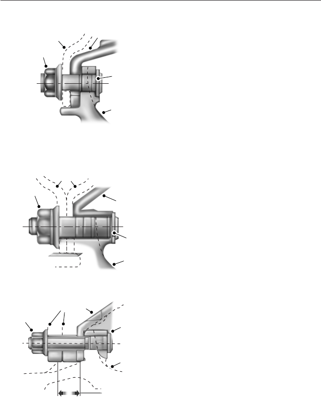
Disc Wheel with Flange Nuts (Hub-piloted).
Front wheel mounting of flange nut
system.
A. Flange nut
B. Wheel(s)
C. Brake drum
D. Wheel stud (22 millimeter)
E. Wheel hub
2. Position the outer rear tire and wheel in place over the studs and
push it back as far as possible. Use care so that the threads on the studs
are not damaged.
Rear wheel mounting of flange nut
system.
A. Flange nut
B. Wheel(s)
C. Brake drum
D. Wheel stud (22 millimeter)
E. Wheel hub
Aluminum Rear Disc Wheel with Flange Nuts (Hub-piloted).
A. Flange nut
B. Wheel(s)
C. Brake drum
D. Wheel stud (22 millimeter)
E. Wheel hub
F. Wheel locator pad
A
BC
D
E
E
D
C
A
B
A
C
D
E
F
B
260 Wheels and Tires
2013 F-650/750 (f67)
Owners Guide gf, 2nd Printing, March 2013
USA (fus)
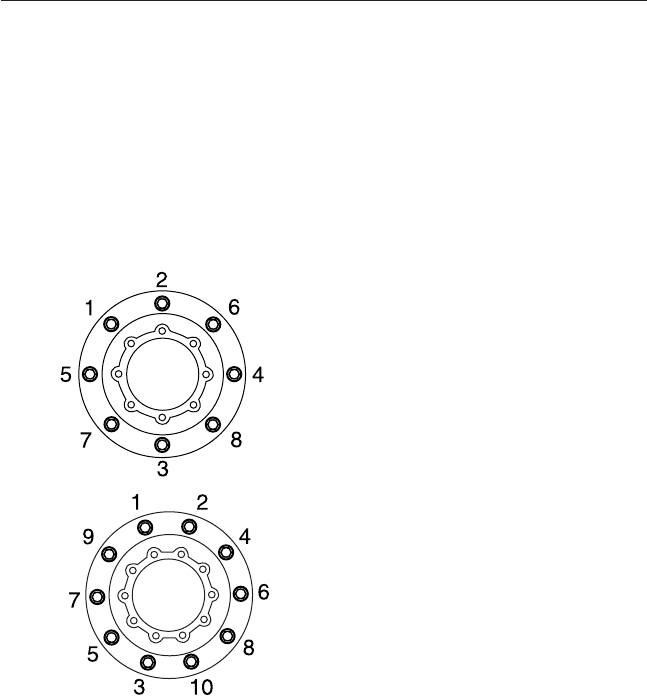
Note for aluminum wheels: Clean each wheel locator pad on the hub
from all dirt, rust and foreign material prior to re-installing rear
aluminum hub-piloted wheels. Apply a light coat of chassis grease,
never-seize or disc brake corrosion control grease, only to the wheel
locator pad.
3. Run the nuts on the studs until they contact the wheel(s). Rotate the
wheel assembly a half-turn to permit the parts to seat.
4. Draw-up the nuts alternately following the crisscross sequence
illustrated under the following wheel tightening sequence illustrations.
Do not fully tighten the nuts. This allows uniform seating of the nuts and
makes sure even face-to-face contact of the wheel and hub.
8–lug wheel
10–lug wheel
5. Continue tightening the nuts to the torque specifications in the torque
chart using the same crisscross sequence shown.
6. After operating the vehicle approximately 50 miles (80 kilometers),
check the nuts for tightness. Some natural seating of parts may be
encountered and the torque on the nuts can drop. Retighten all nuts to
specifications.
Once a week, inspect and retighten the wheel stud nuts.
Wheels and Tires 261
2013 F-650/750 (f67)
Owners Guide gf, 2nd Printing, March 2013
USA (fus)
Note: Make sure the tire valve stem clears the brake caliper when
installing the tire and rim assembly on disc-brake equipped axles. The
use of a tire manufacturer’s stem forming tool is the only acceptable
method of obtaining clearance when necessary.
Proper Torque
It is important to tighten and maintain wheel and rim mounting nuts to
the proper torque. Loose nuts or over-tightened nuts can lead to
premature wear and possible failure of the wheel or mounting hardware.
Changing Wheel Types
WARNING: Use only the same type and style wheels and
mounting hardware to replace original parts. Failure to do so may
result in an assembly that looks fine, but does not fit together properly.
This could possibly cause wheel or fastener failures which could result
in property damage, personal injury or death.
Note: Do not attempt to mix stud-piloted wheels or fasteners with
hub-piloted wheels or fasteners.
Note: Do not change from aluminum wheels to steel wheels or
vice-versa without changing the mounting hardware required or, with
flange nut mounting systems, changing the hub and stud assembly.
Consult your dealer or wheel or rim distributor before attempting any
wheel or fastener changes.
TECHNICAL SPECIFICATIONS
Wheel Lug Nut Torque Specifications
Note: Do not use lubrication on dry threads. Where excessive corrosion
exists, a light coat of lubricant on the first three threads of the stud bolt
is permitted. Keep lubricant away from:
•Hex nut and rim clamp contact surfaces.
•Cap nut ball face and ball seat on the disc wheel.
•Flange nut washer surface and flat on the disc wheel.
Size Nut Mounting Torque
ft-lb N•m
22 mm Flange 450–500 610–678
262 Wheels and Tires
2013 F-650/750 (f67)
Owners Guide gf, 2nd Printing, March 2013
USA (fus)
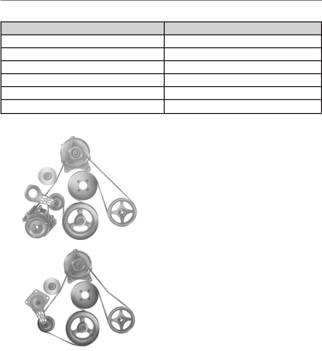
ENGINE SPECIFICATIONS (GASOLINE ENGINE ONLY)
Engine 6.8L V10 engine
Cubic inches 413
Required fuel Minimum 87 octane
Firing order 1-6-5-10-2-7-3-8-4-9
Spark plug gap 0.039–0.043 inch (1.0–1.1 mm)
Ignition system Coil on plug
Compression ratio 9.2:1
Engine Drivebelt Routing
6.8L V10 engine with A/C
6.8L V10 engine - without A/C
Capacities and Specifications 263
2013 F-650/750 (f67)
Owners Guide gf, 2nd Printing, March 2013
USA (fus)

TECHNICAL SPECIFICATIONS
Component Lubrication Type Viscosity / Ambient
Temperature / Notes
Equivalent Ford
Part Name / Number
Non-driving front axle
Eaton-Spicer axle
(generic) - front axle
wheel bearing oil
Multipurpose EP gear
lube of API GL-5
quality meeting
MIL-PRF-2105E
specifications including
synthetic lubricants.
Do not mix
conventional and
synthetic lubricants.
SAE 75W:
–40°F to –15°F
(–40°C to –26°C)
Motorcraft® SAE
75W-140 Synthetic
Rear Axle Lubricant /
XY–75W140–QL
SAE 75W-80:
–40°F to 80°F
(–40°C to 27°C)
SAE 75W-140:
–40°F and above
(–40°C and above)
SAE 80W-140:
–15°F and above
(–26°C and above)
SAE 85W-140:
10°F and above
(–12°C and above)
SAE 80W-90:
–15°F to 100°F
(–26°C to 38°C)
Motorcraft® SAE
80W-90 Premium Rear
Axle Lubricant /
XY–80W90–QL
264 Capacities and Specifications
2013 F-650/750 (f67)
Owners Guide gf, 2nd Printing, March 2013
USA (fus)

Component Lubrication Type Viscosity / Ambient
Temperature / Notes
Equivalent Ford
Part Name / Number
Spicer axle - front axle
wheel bearing oil
Multipurpose EP gear
lube of API GL-5
quality meeting
MIL-PRF-2105E
specifications including
synthetic lubricants.
Do not mix
conventional and
synthetic lubricants.
SAE 75W:
–40°F to 32°F
(–40°C to 0°C)
Motorcraft® SAE
75W-140 Synthetic
Rear Axle Lubricant /
XY–75W140–QL
SAE 75W-140:
–40°F and above
(–40°C and above)
SAE 80W-140:
–15°F and above
(–26°C and above)
SAE 85W-140:
10°F and above
(–12°C and above)
SAE 140W:
40°F and above
(4°C and above)
SAE 80W:
–15°F to 70°F
(–26°C to 21°C)
Motorcraft® SAE
80W-90 Premium Rear
Axle Lubricant /
XY–80W90–QL
SAE 90W:
10°F to 100°F
(–12°C to 38°C)
Capacities and Specifications 265
2013 F-650/750 (f67)
Owners Guide gf, 2nd Printing, March 2013
USA (fus)

Component Lubrication Type Viscosity / Ambient
Temperature / Notes
Equivalent Ford
Part Name / Number
Eaton-Spicer axle,
Spicer axle - Front
axle wheel bearing
grease, tie rod ends,
drag link, kingpin and
bushing
EP2 Lithium
complex-based moly
grease (or equivalent)
GC/LB NLGI #2
multi-purpose lithium
complex grease
Note: Eaton-Spicer
and Meritor Easy Steer
axles: With chassis
load on axle, force
grease through thrust
bearings; then with
axle lifted clear of the
floor, force grease
between kingpin and
bushing surfaces.
Motorcraft® Premium
Long Life Grease /
XG-1-C
Steering
Power steering fluid MERCON® V ATF — MERCON® V /
XT-5-QMC; XT-5-QM;
XL-14
Steering gear Ross TAS
- Output Seal, Steering
column U-joints / slip
joint
GC/LB NLGI #2 lithium
complex-based moly
grease or
multi-purpose lithium
complex grease
— Motorcraft® Premium
Long Life Grease /
XG-1-C
266 Capacities and Specifications
2013 F-650/750 (f67)
Owners Guide gf, 2nd Printing, March 2013
USA (fus)

Component Lubrication Type Viscosity / Ambient
Temperature / Notes
Equivalent Ford
Part Name / Number
Driveshaft
U-joint GC/LB NLGI #2 lithium
complex-based moly
grease or
multi-purpose lithium
complex grease
— Motorcraft® Premium
Long Life Grease /
XG-1-C
Clutch
Release bearing /
shafts / fork
GC/LB NLGI #2 lithium
complex-based moly
grease or
multi-purpose lithium
complex grease
— Motorcraft® Premium
Long Life Grease /
XG-1-C
Reservoir DOT 3, WSS-M6C62-A
or WSS-M6C65-A1
— High Performance DOT
3 Motor Vehicle Brake
Fluid, PM-1-C (U.S.) or
CPM-1-C (Canada)
Cooling System
Engine coolant WSS-M97B44-D2 — Motorcraft® Orange
Antifreeze/Coolant
Prediluted/
VC-3DIL-B (U.S.)
CVC-3DIL-B (Canada)
Capacities and Specifications 267
2013 F-650/750 (f67)
Owners Guide gf, 2nd Printing, March 2013
USA (fus)

Component Lubrication Type Viscosity / Ambient
Temperature / Notes
Equivalent Ford
Part Name / Number
Windshield Washer
Washer fluid WSB-M8B16-A2 — Motorcraft® Premium
Windshield Washer
Concentrate / ZC-32-A
(U.S.) or CXC-37-(A,
B, D, and F) (Canada)
Transmission
Six-speed automatic
(6R140)
— — Motorcraft®
MERCON® LV ATF /
XT-10–QLV
Eaton-Fuller Petroleum oil: Engine
oil API-SL or API-CF
(MIL-L-2104E or
MIL-L-46152E)
SAE 40W:
Below 10°F (–12°C)
—
SAE 50W:
Above 10°F (–12°C)
—
Mineral gear oil:
API-GL-1 (rust and
oxidation inhibited)
SAE 75W:
Below 10°F (–12°C)
—
SAE 80W–90:
Above 10°F (–12°C)
—
Synthetic oil: Eaton®,
Roadranger® synthetic
CD-50 transmission
fluid
CD SAE 50W:
All temperatures
—
268 Capacities and Specifications
2013 F-650/750 (f67)
Owners Guide gf, 2nd Printing, March 2013
USA (fus)

Component Lubrication Type Viscosity / Ambient
Temperature / Notes
Equivalent Ford
Part Name / Number
Spicer
(non-synchronized)
(Lubricants are listed
in order of
preference.)
Petroleum oil: Engine
oil API-SL or API-CF
(MIL-L-2104E or
MIL-L-46152E)
SAE 40W:
Below 0°F (–18°C)
—
SAE 50W:
Above 0°F (–18°C)
—
Mineral gear oil:
API-GL-1 (rust and
oxidation inhibited)
(EP gear oils are not
acceptable.)
SAE 80W:
Below 0°F (–18°C)
—
SAE 90W:
Above 0°F (–18°C)
—
Synthetic oil: Synthetic
engine oil meeting
MIL-L-2104E or
MIL-L-46152E, API-SL
or API-CF
CD SAE 50W:
All temperatures
—
Capacities and Specifications 269
2013 F-650/750 (f67)
Owners Guide gf, 2nd Printing, March 2013
USA (fus)

Component Lubrication Type Viscosity / Ambient
Temperature / Notes
Equivalent Ford
Part Name / Number
Spicer (synchronized)
(Lubricants are listed
in order of
preference.)
Petroleum oil: Engine
oil API-SL or API-CF
(MIL-L-2104E or
MIL-L-46152E)
SAE 40W:
Below 10°F (–12°C)
—
SAE 50W:
Above 10°F (–12°C)
—
Mineral gear oil:
API-GL-1 (rust and
oxidation inhibited)
SAE 80W:
Below 10°F (–12°C)
—
SAE 90W:
Above 10°F (–12°C)
—
Synthetic oil: Synthetic
engine oil meeting
MIL-L-2104E or
MIL-L-46152E, API-SL
or API-CF
SAE 50W:
All temperatures
—
270 Capacities and Specifications
2013 F-650/750 (f67)
Owners Guide gf, 2nd Printing, March 2013
USA (fus)

Component Lubrication Type Viscosity / Ambient
Temperature / Notes
Equivalent Ford
Part Name / Number
Meritor Petroleum oil: Heavy
Duty Engine Oil
MIL-L-2104E or API-SL
or API-CF (previous
API designations
acceptable)
SAE 30W:
Below 10°F (–12°C)
Motorcraft® SAE 30
Super Duty Motor Oil /
XO-30-QSD
SAE 40W or SAE 50W:
Above 10°F (–12°C)
—
Mineral gear oil with
rust and oxidation
inhibitor API-GL-1. Do
not use multi-weight
and GL-5 EP gear
oils; they may cause
transmission failure
or damage.
SAE 80W:
Below 10°F (–12°C)
—
SAE 90W:
Above 10°F (–12°C)
—
Synthetic oil:
MIL-L-2104E or
MIL-L-46152D. Do not
use multi-weight and
GL-5 EP gear oils;
they may cause
transmission failure
or damage.
SAE 50W:
All temperatures
—
Allison See transmission operator’s manual
Capacities and Specifications 271
2013 F-650/750 (f67)
Owners Guide gf, 2nd Printing, March 2013
USA (fus)

Component Lubrication Type Viscosity / Ambient
Temperature / Notes
Equivalent Ford
Part Name / Number
Rear Axle
Eaton-Spicer -
two-speed axle
RHEOLUBE 362 (or
equivalent) (Eaton
part number 113741)
——
Eaton - single-speed
axle
Generic lubricant SAE 75W:
–40°F to –15°F
(–40°C to –26°C)
Motorcraft® SAE
75W-140 Synthetic
Rear Axle Lubricant /
XY–75W140–QL
SAE 75W-80:
–40°F to 80°F
(–40°C to 27°C)
SAE 75W-140:
–40°F and above
(–40°C and above)
SAE 80W-140:
–15°F and above
(–26°C and above)
SAE 85W-140:
10°F and above
(–12°C and above)
SAE 80W-90:
–15°F to 100°F
(–26°C to 38°C)
Motorcraft® SAE
80W-90 Premium Rear
Axle Lubricant /
XY-80W90-QL
272 Capacities and Specifications
2013 F-650/750 (f67)
Owners Guide gf, 2nd Printing, March 2013
USA (fus)

Component Lubrication Type Viscosity / Ambient
Temperature / Notes
Equivalent Ford
Part Name / Number
Spicer - single-speed
axle
Multipurpose EP gear
lube of API GL-5
quality meeting
MIL-PRF-2105E
specifications including
synthetic lubricants
SAE 75W:
–40°F to 32°F
(–40°C to 0°C)
Motorcraft® SAE
75W-140 Synthetic
Rear Axle Lubricant /
XY–75W140–QL
SAE 75W-140:
–40°F and above
(–40°C and above)
SAE 80W:
–15°F to 70°F
(–26°C to 21°C)
SAE 80W-140:
–15°F and above
(–26°C and above)
SAE 85W-140:
10°F and above
(–12°C and above)
SAE 140W:
40°F and above
(4°C and above)
SAE 90W:
10°F to 100°F
(–12°C to 38°C)
Motorcraft® SAE
80W-90 Premium Rear
Axle Lubricant /
XY–80W90–QL
Capacities and Specifications 273
2013 F-650/750 (f67)
Owners Guide gf, 2nd Printing, March 2013
USA (fus)

Component Lubrication Type Viscosity / Ambient
Temperature / Notes
Equivalent Ford
Part Name / Number
Meritor (non-extended
drain lubricants)
Petroleum with EP
additives of API GL-5
quality meeting
MIL-PRF-2105E
specifications
SAE 75W:
Above –40°F (–40°C);
Up to 35°F (2°C)
Motorcraft® SAE
75W-140 Synthetic
Rear Axle Lubricant /
XY–75W140–QL
SAE 75W-90:
Above –40°F (–40°C)
SAE 75W-140:
Above –40°F (–40°C)
SAE 80W-140:
Above –15°F (–26°C)
SAE 85W-140:
Above 10° (–12°C)
SAE 80W-90:
Above –15°F (–26C)
Motorcraft® SAE
80W-90 Premium Rear
Axle Lubricant /
XY-80W90-QL
274 Capacities and Specifications
2013 F-650/750 (f67)
Owners Guide gf, 2nd Printing, March 2013
USA (fus)

Component Lubrication Type Viscosity / Ambient
Temperature / Notes
Equivalent Ford
Part Name / Number
Meritor (extended
drain lubricants)
Petroleum with
extended drain
additives of API GL-5
quality meeting
MIL-PRF-2105E
specifications including
synthetic lubricants
SAE 75W-90:
Above –40°F (–40°C)
(full synthetic)
Motorcraft® SAE
75W-140 Synthetic
Rear Axle Lubricant /
XY–75W140–QL
SAE 75W-140:
Above –40°F (–40°C)
(full synthetic)
SAE 80W-90:
Above –15°F (–26C)
(semi-synthetic)
Motorcraft® SAE
80W-90 Premium Rear
Axle Lubricant /
XY-80W90-QL
SAE 80W-90:
Above –15°F (–26C)
Cab Components
Door check, hinges,
latches and strikers;
Seat adjuster slides
GC/LB NLGI #2 lithium
complex-based moly
grease (or equivalent)
or multi-purpose
lithium complex grease
— Motorcraft® Premium
Long Life Grease /
XG-1-C
Door lock cylinders Lock oil — Motorcraft®
Penetrating and Lock
Lubricant / XL-1
Door window
regulators
NGLI #2 multipurpose
lithium complex grease
— Motorcraft®
Multi-Purpose Grease
Spray / XL-5 or CRC®
SL3151 (or equivalent)
Capacities and Specifications 275
2013 F-650/750 (f67)
Owners Guide gf, 2nd Printing, March 2013
USA (fus)

Component Lubrication Type Viscosity / Ambient
Temperature / Notes
Equivalent Ford
Part Name / Number
Weatherstripping Silicone lubricant — Motorcraft® Silicone
Spray / XL-6
Engine Oil
Diesel engine: See engine operator’s manual.
Gasoline engine: •Motorcraft® SAE
5W-20 Premium
Synthetic Blend Motor
Oil (U.S.)
•Motorcraft® SAE
5W-20 Full Synthetic
Motor Oil (U.S.)
•Motorcraft® SAE
5W-20 Super Premium
Motor Oil (Canada)
•Motorcraft® SAE
5W-20 Synthetic Motor
Oil (Canada) /
WSS-M2C945-A and
API Certification Mark
—•XO-5W20-QSP (U.S.)
•XO-5W20-QFS (U.S.)
•CXO-5W20–LSP12
(Canada)
•CXO-5W-20-LFS12
(Canada)
Brake Fluid
Master cylinder DOT 3, WSS-M6C62-A
or WSS-M6C65-A1
— High Performance DOT
3 Motor Vehicle Brake
Fluid, PM-1-C (U.S.) or
CPM-1-C (Canada)
276 Capacities and Specifications
2013 F-650/750 (f67)
Owners Guide gf, 2nd Printing, March 2013
USA (fus)
REFILL CAPACITIES
Engine Coolant and Engine Oil
Engine Engine Coolant
*
Engine Oil
*
Diesel 26.0 quarts
(24.6L)
**
Refer to engine operator’s manual.
Gasoline 26.3 quarts
(24.9L)
**
7.0 quarts (6.6L) (includes filter
change)
*
Quantities listed are approximate.
**
Add the coolant type originally equipped in your vehicle.
Transmission
Note: Capacities may be increased if the vehicle is equipped with a
cooler. Always check to make sure the fluid level is in the acceptable
range.
Description Capacity - Pints (Liters)
Allison 2000 Series 30.0 (14.2)
*
Allison 3000 Series 37.6 (17.8)
*
TorqShift® six–speed 31.0 (14.9)
5–speed manual 12.5 (5.9)
6–speed manual 19.5 (9.2)
7–speed manual 22.0 (10.4)
*
Total fluid capacity (dry transmission and torque converter).
Rear Axle
Eaton-Spicer
Axle Code Weight Capacity - lb
(kg) Description
Capacity -
Pints
(Liters)
*
S135–S 13500 (6123) Single reduction 24.5 (11.6)
4S150–S 15500 (7031) Single reduction 24.5 (11.6)
17060S 17500 (7938) Single reduction 28.0 (13.2)
19055T 17500 (7938) Two-speed 28.0 (13.2)
19060S 19000 (8618) Single reduction 28.0 (13.2)
M190T 19000 (8618) Two-speed 35.0 (17.0)
Capacities and Specifications 277
2013 F-650/750 (f67)
Owners Guide gf, 2nd Printing, March 2013
USA (fus)
Eaton-Spicer
Axle Code Weight Capacity - lb
(kg) Description
Capacity -
Pints
(Liters)
*
21060S 21000 (9525) Single reduction 28.0 (13.2)
21060D 21000 (9525) Single reduction,
driver-controlled
locking differential
28.0 (13.2)
M210T 21000 (9525) Two-speed 16.0 (33.0)
23090S 23000 (10432) Single reduction 39.0 (18.5)
23090D 23000 (10432) Single reduction,
driver-controlled
locking differential
39.0 (18.5)
23082T 23000 (10432) Two-speed 37.0 (17.5)
*
Quantities listed are approximate. Fill axle until the lubricant level is at
the bottom of the filler hole, with the vehicle on level ground.
If hubs are removed, add an additional 1.6 pints (0.75 liters) of axle
lubricant. Add lubricant through the axle vent.
Meritor
Axle Model Capacity - Pints (Liters)
*
RS-17–140 28.6 (13.5)
RS-17–144 32.0 (15.0)
RS-17–145 33.6 (15.9)
RS-17–220 30.7 (14.5)
RS-17–224 29.0 (13.0)
RS-19–144 32.0 (15.0)
RS-19–145 33.2 (15.7)
RS-19–220 30.0 (14.0)
RS-19–223 29.0 (13.0)
RS-21–145 32.3 (15.3)
RS-21–160 39.0 (18.0)
RS-21–230 38.9 (18.4)
RS-23–160 39.5 (18.7)
RS-23–161 37.2 (17.6)
278 Capacities and Specifications
2013 F-650/750 (f67)
Owners Guide gf, 2nd Printing, March 2013
USA (fus)
Meritor
Axle Model Capacity - Pints (Liters)
*
RS-23–180/186 47.3 (22.4)
RS-23–240 37.4 (17.7)
RS-23–380 63.6 (30.1)
*
Oil capacities are for standard track axles that have been measured at
various common drive pinion angles. The quantities listed include enough
oil for both wheel ends. These capacities change if the track or the drive
pinion angle is different.
Power Steering
Note: Capacities may be increased if the vehicle is equipped with a
cooler. Always check to make sure the fluid level is in the acceptable
range.
Steering Gear Capacity - Pints (Liters)
TAS40 17.6 (8.3)
TAS66 18.4 (8.7)
Air Conditioner Refrigerant
Note: This system uses mineral-based refrigerant oil to lubricate o-rings
and fittings.
This system uses r134a refrigerant and PAG-type refrigerant oil.
Torque the captured washer nut to 170–190 inch-pounds
(19–21 Newton-meters) after servicing.
Fuel Tanks
Standard tanks are listed as such. All other tanks available for your
vehicle are optional equipment.
Gasoline engine
Tank Type Capacity - Gallons (Liters)
Single, steel rectangular 42 (159)
60 (227)
Capacities and Specifications 279
2013 F-650/750 (f67)
Owners Guide gf, 2nd Printing, March 2013
USA (fus)

Diesel engine
Tank Type Capacity - Gallons (Liters)
Single, steel rectangular 35 (132)
Single, steel rectangular 45 (170)
Single, steel rectangular 65 (246)
Single, steel D-style 65 (246)
Single, steel D-style 80 (303)
Dual, steel rectangular 35 (RH)/45 (LH)
(132 [RH]/170 [LH])
Dual, steel rectangular 45/45 (170/170)
Dual, steel D-style 50/50 (189/189)
Dual, steel D-style 65 (RH)/45 (LH)
(246 [RH]/170 [LH])
Dual, steel rectangular 65/65 (246/246)
Dual, steel D-style 80/65 (303/246)
MOTORCRAFT® PART NUMBERS
Component 6.8L V10 Engine
Air filter element FA-1889
Oil filter FL-820-S
Battery (standard) BXT-65-650
Battery (optional) BXT-65-750
Spark plugs-platinum —
*
For spark plug replacement, see your authorized dealer. See the
Scheduled Maintenance chapter for the appropriate intervals for
changing the spark plugs.
Note: Replace the spark plugs with ones that meet Ford material and
design specifications for your vehicle, such as Motorcraft® or equivalent
replacement parts. The customer warranty may be void for any damage
to the engine if such spark plugs are not used.
280 Capacities and Specifications
2013 F-650/750 (f67)
Owners Guide gf, 2nd Printing, March 2013
USA (fus)
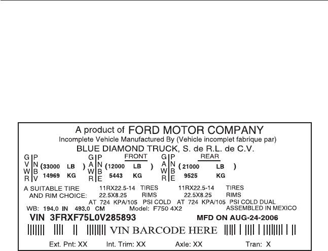
VEHICLE IDENTIFICATION NUMBER
The VIN is printed on the Vehicle Rating Decal attached to the vehicle
on the edge of the driver’s door or B-Pillar. The VIN also serves as the
warranty number. If you ever find it necessary to communicate with Ford
Motor Company about your vehicle, always include the VIN in your
communication.
VEHICLE CERTIFICATION LABEL
The National Highway Traffic Safety Administration Regulations require
that a Safety Compliance Certification Label be affixed to a vehicle and
prescribe where the Safety Compliance Certification Label may be
located. The Safety Compliance Certification Label shall be affixed to
either the door hinge pillar, the door latch post, or the edge of the door
near the door latch, next to the driver’s seating position.
Capacities and Specifications 281
2013 F-650/750 (f67)
Owners Guide gf, 2nd Printing, March 2013
USA (fus)
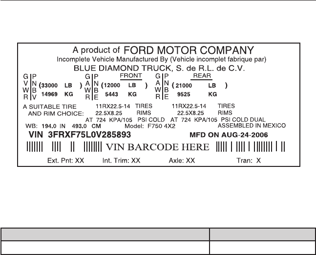
TRANSMISSION CODE DESIGNATION
You can find a transmission code on the Safety Compliance Certification
Label. The following table tells you which transmission each code
represents.
Description Code
Six-speed TorqShift® automatic (6R140) P
282 Capacities and Specifications
2013 F-650/750 (f67)
Owners Guide gf, 2nd Printing, March 2013
USA (fus)

GENERAL MAINTENANCE INFORMATION
Why Maintain Your Vehicle?
Carefully following the maintenance schedule helps protect against major
repair expenses resulting from neglect or inadequate maintenance and
may help to increase the value of your vehicle when you sell or trade it.
Keep all receipts for completed maintenance with your vehicle.
We have established regular maintenance intervals for your vehicle based
upon rigorous testing. It is important that you have your vehicle serviced
at the proper times. These intervals serve two purposes; one is to
maintain the reliability of your vehicle and the second is to keep your
cost of owning your vehicle down.
It is your responsibility to have all scheduled maintenance performed and
to make sure that the materials used meet the specifications identified in
the Capacities and Specifications chapter of this owner’s manual.
Failure to perform scheduled maintenance invalidates warranty coverage
on parts affected by the lack of maintenance.
Protecting Your Investment
Maintenance is an investment that pays dividends in the form of
improved reliability, durability and resale value. To maintain the proper
performance of your vehicle and its emission control systems, make sure
you have scheduled maintenance performed at the designated intervals.
Your vehicle is very sophisticated and built with multiple, complex,
performance systems. Every manufacturer develops these systems using
different specifications and performance features. That is why it is
important to rely upon your dealership to properly diagnose and repair
your vehicle.
Ford Motor Company has recommended maintenance intervals for
various parts and component systems based upon engineering testing.
Ford Motor Company relies upon this testing to determine the most
appropriate mileage for replacement of oils and fluids to protect your
vehicle at the lowest overall cost to you and recommends against
maintenance schedules that deviate from the scheduled maintenance
information.
We strongly recommend the use of only genuine Ford, Motorcraft or
Ford-authorized re-manufactured replacement parts engineered for your
vehicle.
Scheduled Maintenance 283
2013 F-650/750 (f67)
Owners Guide gf, 2nd Printing, March 2013
USA (fus)
Additives and Chemicals
This owner’s manual and the Ford Workshop Manual list the
recommended additives and chemicals for your vehicle. We do not
recommend using chemicals or additives not approved by us as part of
your vehicle’s normal maintenance. Please consult your warranty
information.
Oils, Fluids and Flushing
In many cases, fluid discoloration is a normal operating characteristic
and, by itself, does not necessarily indicate a concern or that the fluid
needs to be changed. However, a qualified expert, such as the
factory-trained technicians at your dealership, should inspect discolored
fluids that also show signs of overheating or foreign material
contamination immediately.
Make sure to change your vehicle’s oils and fluids at the specified
intervals or in conjunction with a repair. Flushing is a viable way to
change fluid for many vehicle sub-systems during scheduled
maintenance. It is critical that systems are flushed only with new fluid
that is the same as that required to fill and operate the system or using a
Ford-approved flushing chemical.
Owner Checks and Services
Certain basic maintenance checks and inspections should be performed
monthly or at six month intervals.
Daily Owner Checks
Engine Air filter restriction gauge.
Engine oil level.
Engine coolant level.
Brake System Air brake reservoir automatic drain valve
operation.
Drain the air brake reservoir (manual valve).
Transmission Visually check for fluid leakage.
Steering System Power steering fluid level.
System for evidence of fluid leaks.
284 Scheduled Maintenance
2013 F-650/750 (f67)
Owners Guide gf, 2nd Printing, March 2013
USA (fus)
Daily Owner Checks
U.S. Department
of Transportation,
Federal Highway
Administration
Requirements
(Make sure the
entire system is
functioning
properly.)
Service brakes and parking brake.
Steering mechanism.
Lighting devices and reflectors.
Tires.
Horn.
Windshield wipers.
Rear vision mirrors.
Wheels and rims.
Emergency equipment.
Every Oil Change
Engine Inspect engine cooling system hoses, clamps and
protection.
*
Inspect drive belt(s).
Exhaust System Inspect entire exhaust system (including the inlet
pipe(s), muffler(s), outlet pipe(s), clamps and
fasteners) for holes, leakage, breakage, corrosive
damage and separation from other components.
Adjust, service or replace with the same or the
equivalent part. (Also a noise emission control
service.)
Suspension Tighten the front and rear spring U-bolts to the
specified torque.
Driveline and
Rear Axle
Lubricate the U-joints and the slip yoke.
Brakes Lubricate the air brake foot control valve, hinge
and roller.
Inspect the drum brake linings through the
inspection holes.
Lubricate the rear caliper slide rails.
Lubricate the brake camshafts and slack adjuster
(air brakes only).
Inspect the disc brake pads and the piston boots
(hydraulic brakes only).
Scheduled Maintenance 285
2013 F-650/750 (f67)
Owners Guide gf, 2nd Printing, March 2013
USA (fus)
Every Oil Change
Clutch Lubricate the clutch release cross shaft and all
linkages.
Check the clutch fluid level.
Fuel System Drain the accumulated water or sediment from
the fuel tank(s).
Steering System Lubricate the steering shaft(s), U-joints and
splines if equipped with grease fittings.
Lubricate the front axle spindle pins.
Lubricate the steering linkage when equipped
with grease fittings.
Lubricate the power steering gear output shaft.
*
Coolant protection checks should be made just prior to the onset of
freezing weather, where applicable. If coolant is dirty or rusty in
appearance, the system should be drained, flushed and refilled with the
prescribed solution of cooling system fluid and distilled water. Use only
permanent type coolant that meets specifications as listed in your engine
operator’s manual. See the engine manufacturer’s operating guide for
supplemental corrosion inhibitor specifications.
Periodic Component/System Checks
The following are vehicle checks that should be made periodically either
by the owner or a qualified technician. It is recommended that
deficiencies be brought to the attention of your dealer or another
qualified service outlet as soon as possible so advice regarding the need
for service or replacement can be obtained.
Frequency Recommended Action
At every engine start up. Check ABS lamp operation.
After first 500 and 1000 miles (800
and 1600 km), then every 500 and
1000 mile (800 and 1600 km)
interval after tire removal or
replacement.
Tighten the wheel mounting nuts
to the specified torque. See
Technical specifications in the
Wheels and Tires chapter.
At least twice annually. Clean body and door drain holes.
As required. Clean windshield wiper blades.
286 Scheduled Maintenance
2013 F-650/750 (f67)
Owners Guide gf, 2nd Printing, March 2013
USA (fus)

Observation Maintenance Operation
Insufficient power shown in loaded
practice stop.
Inspect the automatic slack
adjuster function.
Subpar vehicle handling qualities. Check the operation of the brakes,
clutch and steering.
1,2
Excessive noise from under the
cab or engine compartment.
Inspect the vehicle for missing,
damaged or mislocated noise
shields.
Excessive engine noise. Check the engine performance and
the engine governor.
Engine overheats; excessive fan
noise; fan constantly runs at high
speed or wobbles due to worn
bearings.
Inspect the fan, fan shroud and fan
clutch.
Excessive exhaust noise; smell of
exhaust fumes is experienced.
Inspect the entire exhaust system
for holes, leaks, breakage,
looseness and corrosive damage.
Excessive engine compartment
noise.
Inspect the engine air induction
system (including air ducts and air
filter) for loose, damaged or
missing components.
Poor steering; wandering;
excessive tire wear.
Check front end alignment, inspect
the tires and tire pressure.
3
Vibration or abnormal tire wear
indicating imbalance.
Balance the wheels and the tires.
Hard shifting or excessive
vibration.
Check the transmission and engine
mountings.
2
High effort to shift; noisy
transmission.
Check and adjust transmission
controls.
2
Insufficient full-throttle power;
backfiring.
Check fuel pump pressure.
Radiator cap does not hold
pressure.
Clean the cap seal and cap surface
on the radiator.
Electrical power supply has
diminished.
Check the battery terminals for
corrosion.
Scheduled Maintenance 287
2013 F-650/750 (f67)
Owners Guide gf, 2nd Printing, March 2013
USA (fus)
Observation Maintenance Operation
Cleaning the wiper blades with a
clean cloth and mild detergent and
washing with a cleaner does not
restore a clean wipe.
Replace wiper blades.
Noisy or difficult to operate. Lubricate body lock cylinders.
Headlamp beams in wrong position
when vehicle operating loaded.
Check headlamp alignment.
Windshield washers do not spray
when operated.
Check windshield washer fluid
level. Add fluid if required.
1
During maintenance and repair, protect the fuel tube and the hose
assemblies, power steering lines, and brake lines from external heat,
acids and abrasions that could damage them.
2
Check for (free) linkage action and make sure that (return) spring force
is adequate to maintain pedal free play.
3
Adjust, repair or replace, as required, with the same or equivalent parts.
Emissions Control System
WARNING: Because of high engine compartment and exhaust
system temperatures resulting from emissions equipment, do not
park, idle or operate your vehicle in dry grass or other dry ground
cover where the possibility of ground fire exists.
To make sure the emissions control systems operate effectively, you
should have the services listed in the maintenance schedule performed at
the specified time and mileage intervals. You should avoid running out of
fuel or turning off the ignition while the vehicle is in motion, especially
at high speeds.
Do not make unauthorized modifications to the engine or vehicle.
Modifications causing increased amounts of unburned fuel to reach the
exhaust system can significantly increase the temperature of the engine
compartment and the exhaust system.
Avoid driving your vehicle if it does not operate properly. If the engine
diesels (more than five seconds of engine run-on after shut-off), misfires,
surges, stalls or backfires, see your dealer. Be alert for fluid leakage, odor,
smoke, loss of oil pressure, or charge indicator or over temperature warning.
288 Scheduled Maintenance
2013 F-650/750 (f67)
Owners Guide gf, 2nd Printing, March 2013
USA (fus)

Vehicles equipped with a diesel engine CANNOT use diesel fuel blended
with waste oil if equipped with a catalytic converter-muffler. Waste lube
oil blending in fuel plugs the catalytic converter-muffler, resulting in a
significant loss of engine power.
Noise Emissions Warranty, Prohibited Tampering Acts and
Maintenance
On January 1, 1978, Federal regulations became effective governing the
noise emissions on trucks over 10000 pounds (4536 kilograms) GVWR.
The following statements concerning prohibited tampering acts and
maintenance and the noise warranty are found in the warranty
information, and are applicable to completed trucks.
Tampering with Noise Control System Prohibited
Federal law prohibits the following acts or the causing thereof: (1) The
removal or rendering inoperative, by any person other than for purposes
of maintenance, repair or replacement, of any device or element of
design incorporated into any new vehicle for the purpose of noise control
prior to its sale or delivery to the ultimate purchaser or while it is in use,
or (2) the use of the vehicle after such device or element of design has
been removed or rendered inoperative by any person.
Among those acts presumed to constitute tampering are the following
acts listed:
Vehicle System Acts
Acoustical shielding Removal of noise shields, hood blanket, tunnel
liner or acoustical absorptive material.
Engine Removal or rendering inoperative the engine
speed governor so as to allow engine speed to
exceed manufacturer specifications. Removal of
engine mounted noise shield or oil pan enclosure.
Engine air induction Removal of the air duct, silencer, air cleaner,
and/or air cleaner element and baffle in air
cleaner; re-indexing of air cleaner.
Scheduled Maintenance 289
2013 F-650/750 (f67)
Owners Guide gf, 2nd Printing, March 2013
USA (fus)

Vehicle System Acts
Exhaust Removal or rendering inoperative exhaust system
components including the catalytic converter -
muffler assembly, inlet pipe, outlet pipe,
resonator and flexpipe. Rotation of horizontal
exhaust system directional outlet pipe to cause
the exhaust to be emitted in a direction other
than the orientation the vehicle was originally
produced with.
Engine cooling Removal or rendering inoperative the fan clutch.
Removal or modification of the fan shroud.
Replacing a fixed fan with a fan of increased
diameter, different number of blades or different
pitch width.
DEF (Diesel
exhaust fluid)
Removal or rendering inoperative DEF system
components including the DEF tank, dosing
module, dosing supply module, dosing control
unit, NOx electronic module or NOx sensor.
Emissions Control System(s) Laws
Federal law prohibits vehicle manufacturers, dealers and other persons
engaged in the business of repairing, servicing, selling, leasing or trading
motor vehicles, as well as fleet operators from knowingly removing or
rendering an emissions control device or system inoperative. Further,
modifications of the emissions control system(s) could create liability on
the part of individual owners under the laws of some states. In Canada,
modification of the emissions control system could create liability under
applicable Federal or Provincial laws.
Maintenance
Instructions for maintenance and service of the noise control system
have been included in the required maintenance services and in the
general maintenance section. To further help minimize noise emissions
degradation throughout the life of the vehicle, Ford Motor Company
recommends that this vehicle should be operated in the manner
described within this owner’s manual. Caution should be exercised by the
owner when installing replacement parts to be sure that a tampering act
(as outlined above) is not committed. Note any inspection and service
performed in the maintenance log.
290 Scheduled Maintenance
2013 F-650/750 (f67)
Owners Guide gf, 2nd Printing, March 2013
USA (fus)

Emissions Information Label
Emissions information appears on the Important Engine Information
decal located on or near the engine.
Scheduled Maintenance Services
Maintenance service adjustments must conform to specifications
contained in this manual, and those shown on the Important Engine
Information decal. The following services are to be performed at
scheduled intervals because they are considered essential to the life and
performance of your vehicle. Ford recommends that you perform
maintenance on all designated items to achieve best vehicle operation.
Maintenance intervals are provided for three types of general vehicle
environments: On-Highway, City and Severe Service. In all applications,
the actual interval is determined by monitoring miles (kilometers) and
time and when the engine is due for an oil change. When the engine oil
change is required prior to the truck lubrication interval, it is
recommended that the lubrication be performed at the same time in
order to reduce your vehicle’s time out of service.
Air Brake Adjustment
WARNING: Failure to maintain proper air brake adjustment can
result in reduction or loss of braking ability.
Air brake inspection and adjustment or repairs should be performed by a
qualified service technician in accordance with the instructions in the
service manual.
Scheduled Maintenance 291
2013 F-650/750 (f67)
Owners Guide gf, 2nd Printing, March 2013
USA (fus)

Cam Brakes - Automatic Slack Adjusters
WARNING: Do not manually adjust the automatic slack adjusters
to correct excessive push rod stroke as it may result in reduced
brake effectiveness and a vehicle crash. Excessive push rod stroke
indicates that a problem exists with the automatic adjuster, with the
installation of the adjuster, or with foundation brake components that
manual adjustment does not remedy. Seek service from a qualified
facility for excessive push rod stroke.
Inspect standard air brakes equipped with automatic slack adjusters for
proper brake adjustment as listed in the maintenance schedule charts.
However, more frequent inspection is required if your vehicle’s brakes
are subjected to heavy use or adverse operating conditions such as:
•Frequent brake applications while fully loaded.
•Operation on hilly or mountainous terrain.
•Frequent operation on dirt, gravel or mud.
Some aftermarket brake linings also require more frequent inspections.
292 Scheduled Maintenance
2013 F-650/750 (f67)
Owners Guide gf, 2nd Printing, March 2013
USA (fus)
MAINTENANCE INTERVALS
ON-HIGHWAY - 60000 MILES (96000 KM) OR MORE ANNUALLY
(Miles, kilometers or months - whichever occurs first)
Miles (x 1000) 15 30 45 60 75 90 105 120 135 150
Kilometers (x 1000) 24 48 72 96 120 144 168 192 216 240
Months 3 6 9 12 15 18 21 24 27 30
Engine
Engine oil and filter - change (diesel engine) See manufacturer’s recommendation.
Engine oil and filter - change (gasoline engine) Every 7500 miles (12000 km) or six months
Engine coolant - check level and concentration ••••••••••
Engine coolant - check freeze-protection and additive
(corrosion inhibitor) strength (diesel engine)
••••••••••
Extended life coolant - add extender (diesel engine) See manufacturer’s recommendation.
Extended life coolant - replace (diesel engine) See manufacturer’s recommendation.
Engine coolant - replace (gasoline engine) At six years or 100000 miles (160000 km) (whichever comes
first), then every three years or 50000 miles (80000 km)
Engine air filter - inspect (gasoline engine) ••••••••••
Engine air filter - replace (gasoline engine) •••••
Replace spark plugs ••
Inspect accessory drive belt(s) Inspect at 100000 miles (160000 km) and 120000 miles
(192000 km). Replace at 150000 miles (240000 km) if not
replaced in the last 100000 miles (160000 km).
Scheduled Maintenance 293
2013 F-650/750 (f67)
Owners Guide gf, 2nd Printing, March 2013
USA (fus)

ON-HIGHWAY - 60000 MILES (96000 KM) OR MORE ANNUALLY (Continued)
(Miles, kilometers or months - whichever occurs first)
Miles (x 1000) 15 30 45 60 75 90 105 120 135 150
Kilometers (x 1000) 24 48 72 96 120 144 168 192 216 240
Months 3 6 9 12 15 18 21 24 27 30
Non-driving Front Axle
Drag link/kingpin and bushing/tie rod ends - lubricate ••••••••••
Wheel bearing - grease type - repack •••••
Wheel bearing - oil type - change oil •
Wheel bearing - oil type - check level ••••••••••
Brake System
Master cylinder - check level (hydraulic brakes) ••••••••••
Parking brake relay lever/linkage - lubricate (hydraulic
brakes)
••
S-cam - lubricate (air brakes) ••••••••••
Slack adjusters - lubricate (air brakes) ••
Steering
Power steering filter - replacement Every five years or 500000 miles (800000 km)
Power steering fluid - change •
Power steering fluid - check level ••••••••••
Steering column U-joints/slip joint - lubricate ••••••••••
Steering gear Ross TAS - output shaft - lubricate •••
Driveshaft
U-joint - lubricate (SPL) Every 100000 miles (160000 km) or six months
U-joint and slip joint - lubricate (non-SPL) Every 10000–15000 miles (16000–24000 km) or three months
294 Scheduled Maintenance
2013 F-650/750 (f67)
Owners Guide gf, 2nd Printing, March 2013
USA (fus)

ON-HIGHWAY - 60000 MILES (96000 KM) OR MORE ANNUALLY (Continued)
(Miles, kilometers or months - whichever occurs first)
Miles (x 1000) 15 30 45 60 75 90 105 120 135 150
Kilometers (x 1000) 24 48 72 96 120 144 168 192 216 240
Months 3 6 9 12 15 18 21 24 27 30
Clutch
Release bearing/shafts/forks - lubricate ••••••••••
Transmission
Automatic and Auto-shift See transmission operator’s manual.
Eaton-Fuller manual - petroleum oil - change ••
Eaton-Fuller manual - synthetic oil - change At 500000 miles (800000 km) if factory-filled with synthetic
At 250000 miles (400000 km) if converted to synthetic
Non-Eaton-Fuller manual - check level ••••••••••
Rear Axle
Eaton/Dana/Spicer - check level ••••••••••
Eaton/Dana/Spicer - petroleum oil - change ••
Eaton/Dana/Spicer - synthetic oil - change At 500000 miles (800000 km) if factory-filled with synthetic
At 250000 miles (400000 km) or three years if converted to
synthetic
Meritor - check level Every 25000 miles (40000 km) or fleet maintenance interval
Meritor - filter change Every 100000 miles (160000 km)
Meritor - petroleum oil - change Every 100000 miles (160000 km) or annually
Meritor - synthetic oil - change Linehaul: Every 500000 miles (800000 km) or four years
Intercity coach: Every 250000 miles (400000 km) or four years
Scheduled Maintenance 295
2013 F-650/750 (f67)
Owners Guide gf, 2nd Printing, March 2013
USA (fus)

ON-HIGHWAY - 60000 MILES (96000 KM) OR MORE ANNUALLY (Continued)
(Miles, kilometers or months - whichever occurs first)
Miles (x 1000) 15 30 45 60 75 90 105 120 135 150
Kilometers (x 1000) 24 48 72 96 120 144 168 192 216 240
Months 3 6 9 12 15 18 21 24 27 30
Cab Components
Door hinges/latches/strikers/lock cylinders - lubricate ••
Seat adjuster slides - lubricate ••
Diesel Exhaust Fluid (DEF) System
Check and refill DEF system ••••••••••
296 Scheduled Maintenance
2013 F-650/750 (f67)
Owners Guide gf, 2nd Printing, March 2013
USA (fus)
ON-HIGHWAY - 60000 MILES (96000 KM) OR MORE ANNUALLY
(Miles, kilometers or months - whichever occurs first)
Miles (x 1000) 165 180 195 210 225 240 255 270 285 300
Kilometers (x 1000) 264 288 312 336 360 384 408 432 456 480
Months 33 36 39 42 45 48 51 54 57 60
Engine
Engine oil and filter - change (diesel engine) See manufacturer’s recommendation.
Engine oil and filter - change (gasoline engine) Every 7500 miles (12000 km) or six months
Engine coolant - check level and concentration ••••••••••
Engine coolant - check freeze-protection and additive
(corrosion inhibitor) strength (diesel engine)
••••••••••
Extended life coolant - add extender (diesel engine) See manufacturer’s recommendation.
Extended life coolant - replace (diesel engine) See manufacturer’s recommendation.
Engine coolant - replace (gasoline engine) At six years or 100000 miles (160000 km) (whichever comes
first), then every three years or 50000 miles (80000 km)
Engine air filter - inspect (gasoline engine) ••••••••••
Engine air filter - replace (gasoline engine) •••••
Replace spark plugs •••
Inspect accessory drive belt(s) Inspect at 100000 miles (160000 km) and 120000 miles
(192000 km). Replace at 150000 miles (240000 km) if not
replaced in the last 100000 miles (160000 km).
Scheduled Maintenance 297
2013 F-650/750 (f67)
Owners Guide gf, 2nd Printing, March 2013
USA (fus)

ON-HIGHWAY - 60000 MILES (96000 KM) OR MORE ANNUALLY (Continued)
(Miles, kilometers or months - whichever occurs first)
Miles (x 1000) 165 180 195 210 225 240 255 270 285 300
Kilometers (x 1000) 264 288 312 336 360 384 408 432 456 480
Months 33 36 39 42 45 48 51 54 57 60
Non-driving Front Axle
Drag link/kingpin and bushing/tie rod ends - lubricate ••••••••••
Wheel bearing - grease type - repack •••••
Wheel bearing - oil type - change oil ••
Wheel bearing - oil type - check level ••••••••••
Brake System
Master cylinder - check level (hydraulic brakes) ••••••••••
Parking brake relay lever/linkage - lubricate (hydraulic
brakes)
••
S-cam - lubricate (air brakes) ••••••••••
Slack adjusters - lubricate (air brakes) •••
Steering
Power steering filter - replacement Five years or 500000 miles (800000 km)
Power steering fluid - change ••
Power steering fluid - check level ••••••••••
Steering column U-joints/slip joint - lubricate ••••••••••
Steering gear Ross TAS - output seal - lubricate •••
Driveshaft
U-joint - lubricate (SPL) Every 100000 miles (160000 km) or six months
U-joint and slip joint - lubricate (non-SPL) Every 10000–15000 miles (16000–24000 km) or three months
298 Scheduled Maintenance
2013 F-650/750 (f67)
Owners Guide gf, 2nd Printing, March 2013
USA (fus)

ON-HIGHWAY - 60000 MILES (96000 KM) OR MORE ANNUALLY (Continued)
(Miles, kilometers or months - whichever occurs first)
Miles (x 1000) 165 180 195 210 225 240 255 270 285 300
Kilometers (x 1000) 264 288 312 336 360 384 408 432 456 480
Months 33 36 39 42 45 48 51 54 57 60
Clutch
Release bearing/shafts/fork - lubricate ••••••••••
Transmission
Automatic and Auto-shift See transmission operator’s manual.
Eaton-Fuller manual - petroleum oil - change •••
Eaton-Fuller manual - synthetic oil - change Factory fill with synthetic at 500000 miles (800000 km)
Converted to synthetic at 250000 miles (400000 km)
Non-Eaton-Fuller manual - check level ••••••••••
Rear Axle
Eaton/Dana/Spicer - check level ••••••••••
Eaton/Dana/Spicer - petroleum oil - change •••
Eaton/Dana/Spicer - synthetic oil - change At 500000 miles (800000 km) if factory-filled with synthetic
At 250000 miles (400000 km) or three years if converted to
synthetic
Meritor - check level Every 25000 miles (40000 km), or fleet maintenance interval
Meritor - filter change Every 100000 miles (160000 km)
Meritor - petroleum oil - change Every 100000 miles (160000 km) or annually
Meritor - synthetic oil - change Linehaul: Every 500000 miles (800000 km) or four years
Intercity coach: Every 250000 miles (400000 km) or four years
Scheduled Maintenance 299
2013 F-650/750 (f67)
Owners Guide gf, 2nd Printing, March 2013
USA (fus)

ON-HIGHWAY - 60000 MILES (96000 KM) OR MORE ANNUALLY (Continued)
(Miles, kilometers or months - whichever occurs first)
Miles (x 1000) 165 180 195 210 225 240 255 270 285 300
Kilometers (x 1000) 264 288 312 336 360 384 408 432 456 480
Months 33 36 39 42 45 48 51 54 57 60
Cab Components
Door hinges/latches/strikers/lock cylinders - lubricate •••
Seat adjuster slides - lubricate •••
Diesel Exhaust Fluid (DEF) System
Check and refill DEF system ••••••••••
300 Scheduled Maintenance
2013 F-650/750 (f67)
Owners Guide gf, 2nd Printing, March 2013
USA (fus)

CITY - 60000 MILES (96000 KM) OR FEWER ANNUALLY
(Miles, kilometers or months - whichever occurs first)
Miles (x 1000) 10 20 30 40 50 60 70 80 90 100
Kilometers (x 1000) 16 32 48 64 80 96 112 128 144 160
Months 3 6 9 12 15 18 21 24 27 30
Engine
Engine oil and filter - change (diesel engine) See manufacturer’s recommendation.
Engine oil and filter - change (gasoline engine ) Every 5000 miles (8000 km) or six months
Engine coolant - check level and concentration ••••••••••
Engine coolant - check freeze-protection and additive
(corrosion inhibitor) strength (diesel engine)
••••••••••
Extended life coolant - add extender (diesel engine) See manufacturer’s recommendation.
Extended life coolant - replace (diesel engine) See manufacturer’s recommendation.
Engine coolant - replace (gasoline engine) At six years or 100000 miles (160000 km) (whichever comes
first), then every three years or 50000 miles (80000 km)
Engine air filter - inspect (gasoline engine) ••••••••••
Engine air filter - replace (gasoline engine) •••
Replace spark plugs •
Inspect accessory drive belt(s) Inspect at 100000 miles (160000 km) and 120000 miles
(192000 km). Replace at 150000 miles (240000 km) if not
replaced in the last 100000 miles (160000 km).
Non-driving Front Axle
Drag link/kingpin and bushing/tie rod ends - lubricate ••••••••••
Wheel bearing - grease type - repack ••
Wheel bearing - oil type - change oil ••
Wheel bearing - oil type - check level ••••••••••
Scheduled Maintenance 301
2013 F-650/750 (f67)
Owners Guide gf, 2nd Printing, March 2013
USA (fus)

CITY - 60000 MILES (96000 KM) OR FEWER ANNUALLY (Continued)
(Miles, kilometers or months - whichever occurs first)
Miles (x 1000) 10 20 30 40 50 60 70 80 90 100
Kilometers (x 1000) 16 32 48 64 80 96 112 128 144 160
Months 3 6 9 12 15 18 21 24 27 30
Brake System
Master cylinder - check level (hydraulic brakes) ••••••••••
Parking brake relay lever/linkage - lubricate (hydraulic
brakes)
•••
S-cam - lubricate (air brakes) ••••••••••
Slack adjusters - lubricate (air brakes) ••
Steering
Power steering filter - replacement Five years or 50000 miles (80000 km)
Power steering fluid - change ••
Power steering fluid - check level ••••••••••
Steering column U-joints/slip joint - lubricate ••••••••••
Steering gear Ross TAS - output seal - lubricate •••
Driveshaft
U-joint - lubricate (SPL) Every 25000 miles (40000 km) or six months (whichever comes
first)
U-joint and slip joint - lubricate (non-SPL) Every 5000–8000 miles (8000 km-12000 km) or three months
(whichever comes first)
Clutch
Release bearing/shafts/forks - lubricate ••••••••••
302 Scheduled Maintenance
2013 F-650/750 (f67)
Owners Guide gf, 2nd Printing, March 2013
USA (fus)

CITY - 60000 MILES (96000 KM) OR FEWER ANNUALLY (Continued)
(Miles, kilometers or months - whichever occurs first)
Miles (x 1000) 10 20 30 40 50 60 70 80 90 100
Kilometers (x 1000) 16 32 48 64 80 96 112 128 144 160
Months 3 6 9 12 15 18 21 24 27 30
Transmission
Automatic and Auto-shift See transmission operator’s manual.
Eaton-Fuller manual - petroleum oil - change ••
Non-Eaton-Fuller manual - check level ••••••••••
Rear Axle
Eaton/Dana/Spicer - check level ••••••••••
Eaton/Dana/Spicer - petroleum oil - change ••
Meritor - check level Every 10000 miles (16000 km), once a month or fleet
maintenance interval (whichever comes first)
Meritor - filter change Every 100000 miles (160000 km)
Meritor - petroleum oil - change Every 50000 miles (80000 km) or annually (whichever comes
first)
Meritor - synthetic oil - change Every 250000 miles (400000 km) or every three years
(whichever comes first)
Cab Components
Door hinges/latches/strikers/lock cylinders - lubricate •••
Seat adjuster slides - lubricate •••
Diesel Exhaust Fluid (DEF) System
Check and refill DEF system ••••••••••
Scheduled Maintenance 303
2013 F-650/750 (f67)
Owners Guide gf, 2nd Printing, March 2013
USA (fus)

CITY - 60000 MILES (96000 KM) OR FEWER ANNUALLY
(Miles, kilometers or months - whichever occurs first)
Miles (x 1000) 110 120 130 140 150 160 170 180 190 200
Kilometers (x 1000) 176 192 208 224 240 256 272 288 304 320
Months 33 36 39 42 45 48 51 54 57 60
Engine
Engine oil and filter - change (diesel engine) See manufacturer’s recommendation.
Engine oil and filter - change (gasoline engine) Every 5000 miles (8000 km) or six months
Engine coolant - check level and concentration ••••••••••
Engine coolant - check freeze-protection and additive
(corrosion inhibitor) strength (diesel engine)
••••••••••
Extended life coolant - add extender (diesel engine) See manufacturer’s recommendation.
Extended life coolant - replace (diesel engine) See manufacturer’s recommendation.
Engine coolant - replace (gasoline engine) At six years or 100000 miles (160000 km) (whichever comes
first), then every three years or 50000 miles (80000 km)
Engine air filter - inspect (gasoline engine) ••••••••••
Engine air filter - replace (gasoline engine) •••
Replace spark plugs ••
Inspect accessory drive belt(s) Inspect at 100000 miles (160000 km) and 120000 miles
(192000 km). Replace at 150000 miles (240000 km) if not
replaced in the last 100000 miles (160000 km).
Non-driving Front Axle
Drag link/kingpin and bushing/tie rod ends - lubricate ••••••••••
Wheel bearing - grease type - repack •••
Wheel bearing - oil type - change oil •••
Wheel bearing - oil type - check level ••••••••••
304 Scheduled Maintenance
2013 F-650/750 (f67)
Owners Guide gf, 2nd Printing, March 2013
USA (fus)
CITY - 60000 MILES (96000 KM) OR FEWER ANNUALLY (Continued)
(Miles, kilometers or months - whichever occurs first)
Miles (x 1000) 110 120 130 140 150 160 170 180 190 200
Kilometers (x 1000) 176 192 208 224 240 256 272 288 304 320
Months 33 36 39 42 45 48 51 54 57 60
Brake System
Master cylinder - check level ••••••••••
Parking brake relay lever/linkage - lubricate •••
S-cam - lubricate ••••••••••
Slack adjusters - lubricate •••
Steering
Power steering filter - replacement Five years or 50000 miles (80000 km)
Power steering fluid - change •••
Power steering fluid - check level ••••••••••
Steering column U-joints/slip joint - lubricate ••••••••••
Steering gear Ross TAS - output seal - lubricate •••
Driveshaft
U-joint - lubricate (SPL) Every 25000 miles (40000 km) or six months (whichever comes
first)
U-joint and slip joint - lubricate (non-SPL) Every 5000–8000 miles (8000 km-12000 km) or three months
(whichever comes first)
Clutch
Release bearing/shafts/fork - lubricate ••••••••••
Scheduled Maintenance 305
2013 F-650/750 (f67)
Owners Guide gf, 2nd Printing, March 2013
USA (fus)

CITY - 60000 MILES (96000 KM) OR FEWER ANNUALLY (Continued)
(Miles, kilometers or months - whichever occurs first)
Miles (x 1000) 110 120 130 140 150 160 170 180 190 200
Kilometers (x 1000) 176 192 208 224 240 256 272 288 304 320
Months 33 36 39 42 45 48 51 54 57 60
Transmission
Automatic and Auto-shift See transmission operator’s manual.
Eaton-Fuller manual - petroleum oil - change ••
Eaton-Fuller manual - synthetic oil - change •
Non-Eaton-Fuller manual - check level ••
Rear Axle
Eaton/Dana/Spicer - check level ••••••••••
Eaton/Dana/Spicer - petroleum oil - change ••
Eaton/Dana/Spicer - synthetic oil - change •
Meritor - check level Every 10000 miles (16000 km), once a month, or fleet
maintenance interval (whichever comes first)
Meritor - filter change Every 100000 miles (160000 km)
Meritor - petroleum oil - change Every 50000 miles (80000 km) or annually (whichever comes
first)
Meritor - synthetic oil - change Every 250000 miles (400000 km) or every three years
(whichever comes first)
Cab Components
Door hinges/latches/strikers/lock cylinders - lubricate •••
Seat adjuster slides - lubricate •••
Diesel Exhaust Fluid (DEF) System
Check and refill DEF system ••••••••••
306 Scheduled Maintenance
2013 F-650/750 (f67)
Owners Guide gf, 2nd Printing, March 2013
USA (fus)

SEVERE SERVICE - ON/OFF ROAD IN DIRTY CONDITIONS OR 20000 MILES (32000 KM) OR FEWER
ANNUALLY
(Miles, kilometers or months - whichever occurs first)
Miles (x 1000) 5 10 15 20 25 30 35 40 45 50
Kilometers (x 1000) 8 16 24 32 40 48 56 64 72 80
Months 3 6 9 12 15 18 21 24 27 30
Engine
Engine oil and filter - change (diesel engine) See manufacturer’s recommendation.
Engine oil and filter - change (gasoline engine) Every 5000 miles (8000 km) or three months (See note at end
of table regarding alternate schedule.)
Engine coolant - check level and concentration ••••••••••
Engine coolant - check freeze-protection and additive
(corrosion inhibitor) strength (diesel engine)
••••••••••
Extended life coolant - add extender (diesel engine) See manufacturer’s recommendation.
Extended life coolant - replace (diesel engine) See manufacturer’s recommendation.
Engine coolant - replace (gasoline engine) At six years or 100000 miles (160000 km) (whichever comes
first), then every three years or 50000 miles (80000 km)
Engine air filter - inspect (gasoline engine) ••••••••••
Engine air filter - replace (gasoline engine) •
Non-driving Front Axle
Drag link/kingpin and bushing/tie rod ends - lubricate ••••••••••
Wheel bearing - grease type - repack ••
Wheel bearing - oil type - change oil ••
Wheel bearing - oil type - check level ••••••••••
Scheduled Maintenance 307
2013 F-650/750 (f67)
Owners Guide gf, 2nd Printing, March 2013
USA (fus)

SEVERE SERVICE - ON/OFF ROAD IN DIRTY CONDITIONS OR 20000 MILES (32000 KM) OR FEWER
ANNUALLY (Continued)
(Miles, kilometers or months - whichever occurs first)
Miles (x 1000) 5 10 15 20 25 30 35 40 45 50
Kilometers (x 1000) 8 16 24 32 40 48 56 64 72 80
Months 3 6 9 12 15 18 21 24 27 30
Brake System
Master cylinder - check fluid level (hydraulic brakes) •••
Parking brake relay lever/linkage - lubricate (hydraulic
brakes)
•••
S-cam - lubricate (air brakes) ••••••••••
Slack adjusters - lubricate (air brakes) ••
Steering
Power steering fluid - change ••
Power steering fluid - check level ••••••••••
Steering column U-joints/slip joints - lubricate ••••••••••
Steering gear Ross TAS - output seal - lubricate •••
Driveshaft
Slip joint - inspect boot; U-joint - lubricate (SPL) Every 25000 miles (40000 km) or six months (whichever comes
first)
U-joint and slip joint - lubricate (non-SPL) Every 5000–8000 miles (8000–12000 km) or three months
(whichever comes first)
Clutch
Release bearing/shafts/forks ••••••••••
308 Scheduled Maintenance
2013 F-650/750 (f67)
Owners Guide gf, 2nd Printing, March 2013
USA (fus)
SEVERE SERVICE - ON/OFF ROAD IN DIRTY CONDITIONS OR 20000 MILES (32000 KM) OR FEWER
ANNUALLY (Continued)
(Miles, kilometers or months - whichever occurs first)
Miles (x 1000) 5 10 15 20 25 30 35 40 45 50
Kilometers (x 1000) 8 16 24 32 40 48 56 64 72 80
Months 3 6 9 12 15 18 21 24 27 30
Transmission
Automatic and Auto-shift See transmission operator’s manual.
Eaton-Fuller manual - petroleum oil - change ••
Non-Eaton-Fuller manual - check level ••••••••••
Rear Axle
Eaton/Dana/Spicer - check level ••••••••••
Eaton/Dana/Spicer - petroleum oil - change •••
Eaton/Dana/Spicer - synthetic oil - change ••
Meritor - check level Every 5000 miles (8000 km), once a month, or fleet
maintenance interval (whichever comes first). For continuous
heavy-duty operation, check level every 1000 miles (1600 km).
Meritor - filter change Every 100000 miles (160000 km)
Meritor - petroleum oil - change Every 25000 miles (40000 km) or annually (whichever comes
first)
Meritor - synthetic oil - change Every 100000 miles (160000 km) or annually (whichever comes
first)
Scheduled Maintenance 309
2013 F-650/750 (f67)
Owners Guide gf, 2nd Printing, March 2013
USA (fus)

SEVERE SERVICE - ON/OFF ROAD IN DIRTY CONDITIONS OR 20000 MILES (32000 KM) OR FEWER
ANNUALLY (Continued)
(Miles, kilometers or months - whichever occurs first)
Miles (x 1000) 5 10 15 20 25 30 35 40 45 50
Kilometers (x 1000) 8 16 24 32 40 48 56 64 72 80
Months 3 6 9 12 15 18 21 24 27 30
Cab Components
Door hinges/latches/strikers/lock cylinders - lubricate ••
Seat adjuster slides - lubricate ••
Diesel Exhaust Fluid (DEF) System
Check and refill DEF system ••••••••••
Note: If your vehicle is equipped with a gasoline engine, the engine oil and filter changes should
observe the normal schedule unless conditions, such as low-speed operation or stationary use, exist
where a schedule based on engine hours is recommended. In this type of schedule, the engine oil
and filter should be replaced every 250 engine hours.
310 Scheduled Maintenance
2013 F-650/750 (f67)
Owners Guide gf, 2nd Printing, March 2013
USA (fus)
SEVERE SERVICE - ON/OFF ROAD IN DIRTY CONDITIONS OR 20000 MILES (32000 KM) OR FEWER
ANNUALLY
(Miles, kilometers or months - whichever occurs first)
Miles (x 1000) 55 60 65 70 75 80 85 90 95 100
Kilometers (x 1000) 88 96 104 112 120 128 136 144 152 160
Months 33 36 39 42 45 48 51 54 57 60
Engine
Engine oil and filter - change (diesel engine) See manufacturer’s recommendation.
Engine oil and filter - change (gasoline engine) Every 5000 miles (8000 km) or three months (see note at end
of table regarding alternate schedule)
Engine coolant - check level and concentration ••••••••••
Engine coolant - check freeze-protection and additive
(corrosion inhibitor) strength (diesel engine)
••••••••••
Extended life coolant - add extender (diesel engine) See manufacturer’s recommendation.
Extended life coolant - replace (diesel engine) See manufacturer’s recommendation.
Engine coolant - replace (gasoline engine) At six years or 100000 miles (160000 km) (whichever comes
first), then every three years or 50000 miles (80000 km)
Engine air filter - inspect (gasoline engine) ••••••••••
Engine air filter - replace (gasoline engine) ••
Replace spark plugs •
Inspect accessory drive belt(s) Inspect at 100000 miles (160000 km) and 120000 miles
(192000 km). Replace at 150000 miles (240000 km) if not
replaced in the last 100000 miles (160000 km).
Scheduled Maintenance 311
2013 F-650/750 (f67)
Owners Guide gf, 2nd Printing, March 2013
USA (fus)

SEVERE SERVICE - ON/OFF ROAD IN DIRTY CONDITIONS OR 20000 MILES (32000 KM) OR FEWER
ANNUALLY (Continued)
(Miles, kilometers or months - whichever occurs first)
Miles (x 1000) 55 60 65 70 75 80 85 90 95 100
Kilometers (x 1000) 88 96 104 112 120 128 136 144 152 160
Months 33 36 39 42 45 48 51 54 57 60
Non-driving Front Axle
Drag link/kingpin and bushing/tie rod ends - lubricate ••••••••••
Wheel bearing - grease type - repack •••
Wheel bearing - oil type - change oil •••
Wheel bearing - oil type - check level ••••••••••
Brake System
Master cylinder - check fluid level (hydraulic brakes) ••••••••••
Parking brake relay lever/linkage - lubricate (hydraulic
brakes)
•••
S-cam - lubricate (air brakes) ••••••••••
Slack adjusters - lubricate (air brakes) •••
Steering
Power steering filter - replacement •
Power steering fluid - change •••
Power steering fluid - check level ••••••••••
Steering column U-joints/slip joint - lubricate ••••••••••
Steering gear Ross TAS - output seal - lubricate •••
312 Scheduled Maintenance
2013 F-650/750 (f67)
Owners Guide gf, 2nd Printing, March 2013
USA (fus)

SEVERE SERVICE - ON/OFF ROAD IN DIRTY CONDITIONS OR 20000 MILES (32000 KM) OR FEWER
ANNUALLY (Continued)
(Miles, kilometers or months - whichever occurs first)
Miles (x 1000) 55 60 65 70 75 80 85 90 95 100
Kilometers (x 1000) 88 96 104 112 120 128 136 144 152 160
Months 33 36 39 42 45 48 51 54 57 60
Driveshaft
Slip joint - inspect boot; U-joint - lubricate (SPL) Every 25000 miles (40000 km) or six months (whichever comes
first)
U-joint and slip joint - lubricate (non-SPL) Every 5000–8000 miles (8000–12000 km) or three months
(whichever comes first)
Clutch
Release bearing/shafts/fork - lubricate ••••••••••
Transmission
Automatic and Auto-shift See transmission operator’s manual.
Non-Eaton-Fuller manual - check level ••••••••••
Eaton-Fuller manual - petroleum oil - change •••
Eaton-Fuller manual - synthetic oil - change ••
Rear Axle
Eaton/Dana/Spicer - check level ••••••••••
Eaton/Dana/Spicer - petroleum oil - change •••
Eaton/Dana/Spicer - synthetic oil - change ••
Meritor - check level Every 5000 miles (8000 km), once a month, or fleet
maintenance interval (whichever comes first). For continuous
heavy-duty operation, check level every 1000 miles (1600 km).
Scheduled Maintenance 313
2013 F-650/750 (f67)
Owners Guide gf, 2nd Printing, March 2013
USA (fus)
SEVERE SERVICE - ON/OFF ROAD IN DIRTY CONDITIONS OR 20000 MILES (32000 KM) OR FEWER
ANNUALLY (Continued)
(Miles, kilometers or months - whichever occurs first)
Miles (x 1000) 55 60 65 70 75 80 85 90 95 100
Kilometers (x 1000) 88 96 104 112 120 128 136 144 152 160
Months 33 36 39 42 45 48 51 54 57 60
Meritor - filter change Every 100000 miles (160000 km)
Meritor - petroleum oil - change Every 25000 miles (40000 km) or annually (whichever comes
first)
Meritor - synthetic oil - change Every 100000 miles (160000 km) or annually (whichever comes
first)
Cab Components
Door hinges/latches/strikers/lock cylinders - lubricate •••
Seat adjuster slides - lubricate •••
Diesel Exhaust Fluid (DEF) System
Check and refill DEF system ••••••••••
Note: If your vehicle is equipped with a gasoline engine, the engine oil and filter changes should
observe the normal schedule unless conditions, such as low-speed operation or stationary use, exist
where a schedule based on engine hours is recommended. In this type of schedule, the engine oil
and filter should be replaced every 250 engine hours.
314 Scheduled Maintenance
2013 F-650/750 (f67)
Owners Guide gf, 2nd Printing, March 2013
USA (fus)

Maintenance Record Retention and Service Log
MAINTENANCE SERVICES AND RECORD RETENTION
The maintenance record form which follows is for your convenience. In addition to recording the services performed, you should
retain copies of your receipts for the services. You also should keep records of any emission control systems maintenance
services performed on your vehicle.
Maintenance Record
Warranty
Start Date ______________________________________ Engine Displacement ______________________________________
Vehicle
Identification
Number _________________________________________ Owner Name ___________________________________________
IMPORTANT — This document should remain with the vehicle at all times.
Scheduled Maintenance 315
2013 F-650/750 (f67)
Owners Guide gf, 2nd Printing, March 2013
USA (fus)

DEALER VALIDATION:
P&A CODE:
RO#: HOURS:
DATE :MILEAGE:
DEALER VALIDATION:
P&A CODE:
RO#: HOURS:
DATE :MILEAGE:
DEALER VALIDATION:
P&A CODE:
RO#: HOURS:
DATE :MILEAGE:
DEALER VALIDATION:
P&A CODE:
RO#: HOURS:
DATE :MILEAGE:
DEALER VALIDATION:
P&A CODE:
RO#: HOURS:
DATE :MILEAGE:
DEALER VALIDATION:
P&A CODE:
RO#: HOURS:
DATE :MILEAGE:
DEALER VALIDATION:
P&A CODE:
RO#: HOURS:
DATE :MILEAGE:
DEALER VALIDATION:
P&A CODE:
RO#: HOURS:
DATE :MILEAGE:
DEALER VALIDATION:
P&A CODE:
RO#: HOURS:
DATE :MILEAGE:
DEALER VALIDATION:
P&A CODE:
RO#: HOURS:
DATE :MILEAGE:
316 Scheduled Maintenance
2013 F-650/750 (f67)
Owners Guide gf, 2nd Printing, March 2013
USA (fus)

DEALER VALIDATION:
P&A CODE:
RO#: HOURS:
DATE :MILEAGE:
DEALER VALIDATION:
P&A CODE:
RO#: HOURS:
DATE :MILEAGE:
DEALER VALIDATION:
P&A CODE:
RO#: HOURS:
DATE :MILEAGE:
DEALER VALIDATION:
P&A CODE:
RO#: HOURS:
DATE :MILEAGE:
DEALER VALIDATION:
P&A CODE:
RO#: HOURS:
DATE :MILEAGE:
DEALER VALIDATION:
P&A CODE:
RO#: HOURS:
DATE :MILEAGE:
DEALER VALIDATION:
P&A CODE:
RO#: HOURS:
DATE :MILEAGE:
DEALER VALIDATION:
P&A CODE:
RO#: HOURS:
DATE :MILEAGE:
DEALER VALIDATION:
P&A CODE:
RO#: HOURS:
DATE :MILEAGE:
DEALER VALIDATION:
P&A CODE:
RO#: HOURS:
DATE :MILEAGE:
Scheduled Maintenance 317
2013 F-650/750 (f67)
Owners Guide gf, 2nd Printing, March 2013
USA (fus)

DEALER VALIDATION:
P&A CODE:
RO#: HOURS:
DATE :MILEAGE:
DEALER VALIDATION:
P&A CODE:
RO#: HOURS:
DATE :MILEAGE:
DEALER VALIDATION:
P&A CODE:
RO#: HOURS:
DATE :MILEAGE:
DEALER VALIDATION:
P&A CODE:
RO#: HOURS:
DATE :MILEAGE:
DEALER VALIDATION:
P&A CODE:
RO#: HOURS:
DATE :MILEAGE:
DEALER VALIDATION:
P&A CODE:
RO#: HOURS:
DATE :MILEAGE:
DEALER VALIDATION:
P&A CODE:
RO#: HOURS:
DATE :MILEAGE:
DEALER VALIDATION:
P&A CODE:
RO#: HOURS:
DATE :MILEAGE:
DEALER VALIDATION:
P&A CODE:
RO#: HOURS:
DATE :MILEAGE:
DEALER VALIDATION:
P&A CODE:
RO#: HOURS:
DATE :MILEAGE:
318 Scheduled Maintenance
2013 F-650/750 (f67)
Owners Guide gf, 2nd Printing, March 2013
USA (fus)
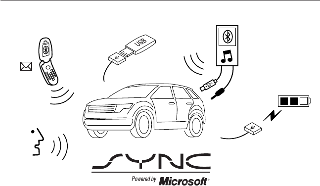
SYNC is an in-vehicle communications system that works with your
Bluetooth-enabled cellular phone and portable media player. This allows
you to:
•Make and receive calls.
•Access and play music from your portable music player.
•Use 911 Assist, Vehicle Health Report and SYNC Services (Traffic,
Directions & Information) (if equipped).
•Use applications, such as Pandora and Stitcher, via SYNC AppLink™
(if applicable).
•Access phonebook contacts and music via voice commands.
•Stream music from your connected phone.
•Text message.
•Use the advanced voice recognition system.
•USB device charging (if your device supports this).
SYNC® 319
2013 F-650/750 (f67)
Owners Guide gf, 2nd Printing, March 2013
USA (fus)

GENERAL INFORMATION
Make sure you review your device’s manual before using it with SYNC.
Support
The SYNC support team is available to help you with any questions you
cannot answer on your own.
Monday-Saturday, 8:30am-8:00pm EST.
In the United States, call: 1–888–270–1055.
In Canada, call: 1–800–565–3673.
Times are subject to change due to holidays.
SYNC Owner Account
Why do I need a SYNC owner account?
•Required to activate Vehicle Health Report and to view the reports
online.
•Required to activate the subscription-based SYNC Services and to
personalize your Saved Points and Favorites.
•Essential for keeping up with the latest software downloads available
for SYNC.
•Access to customer support for any questions you may have.
Driving Restrictions
For your safety, certain features are speed-dependent and restricted
when your vehicle is traveling over 3 mph (5 km/h).
Safety Information
WARNING: Driving while distracted can result in loss of vehicle
control, crash and injury. We strongly recommend that you use
extreme caution when using any device that may take your focus off
the road. Your primary responsibility is the safe operation of your
vehicle. We recommend against the use of any handheld device while
driving and encourage the use of voice-operated systems when possible.
Make sure you are aware of all applicable local laws that may affect the
use of electronic devices while driving.
When using SYNC:
•Do not operate playing devices if the power cords or cables are
broken, split or damaged. Place cords and cables out of the way, so
they do not interfere with the operation of pedals, seats,
compartments or safe driving abilities.
320 SYNC®
2013 F-650/750 (f67)
Owners Guide gf, 2nd Printing, March 2013
USA (fus)

•Do not leave playing devices in your vehicle during extreme conditions
as it could cause them damage. See your device’s manual for further
information.
•Do not attempt to service or repair the system. See your authorized
dealer.
For your safety, some SYNC functions are speed-dependent. Their use is
limited to when your vehicle is traveling at speeds under 3 mph
(5 km/h).
Make sure that you review your device’s manual before using it with
SYNC.
Privacy Information
When a cellular phone is connected to SYNC, the system creates a profile
within your vehicle that is linked to that cellular phone. This profile is
created in order to offer you more cellular features and to operate more
efficiently. Among other things, this profile may contain data about your
cellular phone book, text messages (read and unread), and call history,
including history of calls when your cell phone was not connected to the
system. In addition, if you connect a media device, the system creates and
retains an index of supported media content. The system also records a
short development log of approximately 10 minutes of all recent system
activity. The log profile and other system data may be used to improve the
system and help diagnose any problems that may occur.
The cellular profile, media device index, and development log remain in
the vehicle unless you delete them and are generally accessible only in
the vehicle when the cellular phone or media player is connected. If you
no longer plan to use the system or the vehicle, we recommend you
perform a Master Reset to erase all stored information.
System data cannot be accessed without special equipment and access to
the vehicle’s SYNC module. Ford Motor Company and Ford of Canada do
not access the system data for any purpose other than as described absent
consent, a court order, or where required by law enforcement, other
government authorities, or other third parties acting with lawful authority.
Other parties may seek to access the information independently of Ford
Motor Company and Ford of Canada. For further privacy information, see
the sections on 911 Assist, Vehicle Health Report, and Traffic, Directions
and Information.
SYNC® 321
2013 F-650/750 (f67)
Owners Guide gf, 2nd Printing, March 2013
USA (fus)
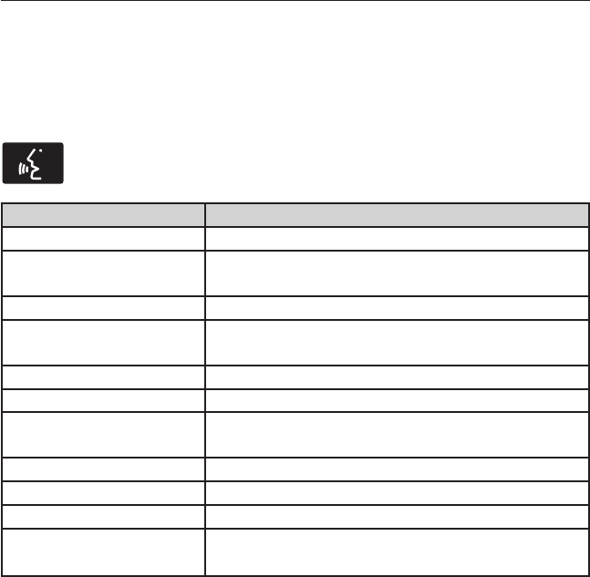
USING VOICE RECOGNITION
This system helps you control many features using voice commands. This
allows you to keep your hands on the wheel and focus on what is in
front of you.
Initiating a Voice Session
Push the voice icon; a tone sounds and Listening appears in the
display. Say any of the following:
Say: If you want to:
“Phone” Make calls.
“USB” Access the device connected to your USB
port.
“Bluetooth Audio” Stream audio from your phone.
“Line in” Access the device connected to the auxiliary
input jack.
“Cancel” Cancel the requested action.
“SYNC” Return to the main menu.
“Voice settings” Adjust the level of voice interaction and
feedback.
“Vehicle Health Report” Run a vehicle health report.
*
“Services” Access the SYNC Services portal.
*
“Mobile apps” Access mobile applications.
*
“Help” Hear a list of voice commands available in the
current mode.
*
If equipped, U.S. only.
System Interaction and Feedback
The system provides feedback through audible tones, prompts, questions
and spoken confirmations depending on the situation and the chosen
level of interaction (voice settings). You can customize the voice
recognition system to provide more or less instruction and feedback.
The default setting is to a higher level of interaction in order to help you
learn to use the system. You can change these settings at any time.
322 SYNC®
2013 F-650/750 (f67)
Owners Guide gf, 2nd Printing, March 2013
USA (fus)
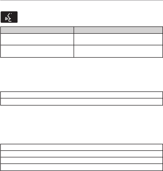
Adjusting the Interaction Level
Push the voice icon; when prompted, say “Voice settings”, then
any of the following:
When you say: The system:
“Interaction mode standard” Provides more detailed interaction and
guidance.
“Interaction mode advanced” Provides less audible interaction and
more tone prompts.
The system defaults to the standard interaction mode.
Confirmation prompts are short questions the system asks when it is not
sure of your request or when there are multiple possible responses to your
request. (For example, the system may ask “Phone, is that correct?”) If
turned off, the system simply makes a best guess as to what you requested
and you may still occasionally be asked to confirm settings.
“Confirmation prompts on”
“Confirmation prompts off”
The system creates candidate lists when it has the same confidence level
of several options based on your voice command. When turned on, you
may be prompted with as many as four possibilities for clarification.
For example, “Say 1 after the tone to call John Doe at home. Say 2 after
the tone to call Johnny Doe on mobile. Say 3 after the tone to call Jane
Doe at home.” Or, “Say 1 after the tone to play John Doe, Say 2 after the
tone to play Johnny Doe.”
“Phone candidate lists on”
“Phone candidate lists off”
“Media candidate lists on”
“Media candidate lists off”
Helpful Hints
•Make sure the interior of the vehicle is as quiet as possible. Wind
noise from open windows and road vibrations may prevent the system
from correctly recognizing spoken commands.
•After pressing the voice icon, wait until after the tone sounds and
Listening appears before saying a command. Any command spoken
prior to this does not register with the system.
•Speak naturally, without long pauses between words.
•At any time you can interrupt the system while it is speaking by
pressing the voice icon.
SYNC® 323
2013 F-650/750 (f67)
Owners Guide gf, 2nd Printing, March 2013
USA (fus)

USING SYNC WITH YOUR PHONE
Hands-free calling is one of the main features of SYNC. While the system
supports a variety of features, many are dependent on your cellular
phone’s functionality. At a minimum, most cellular phones with Bluetooth
wireless technology support the following functions:
•Answering an incoming call
•Ending a call
•Using privacy mode
•Dialing a number
•Redialing
•Call waiting notification
•Caller ID.
Other features, such as text messaging using Bluetooth and automatic
phonebook download, are phone-dependent features. To check your
phone’s compatibility, see your phone’s user manual and visit
www.SYNCMyRide.com, www.SYNCMyRide.ca or www.syncmaroute.ca.
Pairing a Phone for the First Time
Note: SYNC can support downloading up to approximately 1000 entries
per Bluetooth-enabled cellular phone.
Note: Make sure the vehicle ignition and radio are turned on and the
transmission is in position P.
Note: To scroll through the menus, press the up and down arrows on
your audio system.
Wirelessly pairing your phone with SYNC allows you to make and receive
hands-free calls.
1. Press the phone button; when the display indicates no phone is
paired, press OK.
2. When Find SYNC appears in the display, press OK.
3. Put your phone into Bluetooth discovery mode. See your phone’s
user guide if necessary.
4. When prompted on your phone’s display, enter the six-digit PIN
provided by SYNC in the radio display.
5. The display indicates when the pairing is successful.
Depending on your phone’s capability and your market, the system may
prompt you with questions such as setting the current phone as the
primary phone (the phone SYNC automatically tries to connect with first
upon vehicle start-up), downloading your phone book, etc.
324 SYNC®
2013 F-650/750 (f67)
Owners Guide gf, 2nd Printing, March 2013
USA (fus)
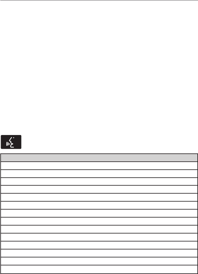
Pairing Subsequent Phones
Note: To scroll through the menus, press the up and down arrows on
your audio system.
Note: Make sure the vehicle ignition and radio are turned on and that
the transmission is in position P.
1. Press the phone button and scroll until System Settings is selected.
2. Press OK and scroll until Bluetooth Devices is selected and press OK.
3. Scroll until Add Bluetooth Device is selected and press OK.
4. When Find SYNC appears in the display, press OK.
5. Put your phone into Bluetooth discovery mode. See your phone’s
user guide if necessary.
6. When prompted on your phone’s display, enter the six-digit PIN
provided by SYNC in the radio display. The display indicates when
the pairing is successful.
7. The system then prompts with questions such as if you would like to
set the current phone as the primary phone (the phone SYNC
automatically tries to connect with first upon vehicle start-up),
download your phone book, etc.
Phone Voice Commands
Press the voice icon and say “Phone”. Say any of the following:
“PHONE”
“Call <name>”
1,2
“Call <name> on mobile OR cell”
1,2
“Call <name> on other”
1,2
“Phone book <name> at home”
2
“Phone book <name> on mobile OR cell”
2
“Call history outgoing”
2
“Phone book <name> on Other”
2
“Call history missed”
2
“Menu”
2,3
“Join”
“Call <name> at home”
1,2
“Call <name> at work” OR “Call <name> in office”
1,2
“Dial”
1,4
“Phone book <name>”
2
SYNC® 325
2013 F-650/750 (f67)
Owners Guide gf, 2nd Printing, March 2013
USA (fus)

“PHONE”
“Phone book <name> at work” OR “Phone book <name> at office”
2
“Call history incoming”
2
“Connections”
2
“Go to privacy”
“Hold”
1
These commands do not require you to say “Phone” first.
2
These commands are not available until phone information is completely
downloaded using Bluetooth.
3
See “MENU” table below.
4
See “DIAL” table below.
“MENU”
“(Phone) connections”
*
“(Phone) settings (message) notification off”
*
“(Phone) settings (message) notification on”
*
“(Phone) settings (set) phone ringer”
*
“(Phone) settings (set) ringer 1”
*
“(Phone) settings (set) ringer 2”
*
“(Phone) settings (set) ringer 3”
*
“(Phone) settings (set) ringer off”
*
“Battery”
“Phone name”
“Signal”
“Text message inbox”
*
Words in ( ) are optional and do not have to be spoken for the system
to understand the command.
326 SYNC®
2013 F-650/750 (f67)
Owners Guide gf, 2nd Printing, March 2013
USA (fus)
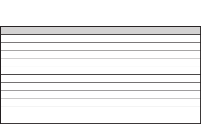
Phone book commands: When you ask SYNC® to access a phone book
name, number, etc., the requested information appears in the display to
view. Press the phone button and say “Call” to call the contact.
“DIAL”
“411” (four-one-one), “911” (nine-one-one)
“700 (seven hundred)” (seven hundred)
“800 (eight hundred)” (eight hundred)
“900 (nine hundred)” (nine hundred)
“#” (pound)
“<number> 0–9”
“Asterisk” (*)
“Clear” (deletes all entered digits)
“Delete” (deletes one digit)
“Plus”
“Star”
Note: To exit dial mode, press and hold the phone button or press
MENU to go to the PHONE menu.
Making Calls
Press the voice icon and when prompted say:
1. Say “Call <name>” or “Dial”, then the desired number.
2. When the system confirms the number, say “Dial” again to initiate the
call.
To erase the last spoken digit, say “Delete” or press the left arrow
button. To erase all spoken digits, say “Clear” or press and hold the left
arrow button.
To end the call, press and hold the phone button.
Receiving Calls
When receiving a call, you can:
•Answer the call by pressing the phone button.
•Reject the call by pressing and holding the phone button.
•Ignore the call by doing nothing.
SYNC® 327
2013 F-650/750 (f67)
Owners Guide gf, 2nd Printing, March 2013
USA (fus)

Phone Options during an Active Call
During an active call, you have additional menu features which become
available such as putting a call on hold, joining calls, etc. Use the arrow
buttons to scroll through the menu options.
To access:
1. Press MENU during an active call.
2. When Active Call Menu is selected, press OK.
3. Scroll to cycle through the following options:
When you
select:
You can:
Mute Call? Mute the call.
Privacy Switch a call from an active hands-free environment to
your cellular phone for a more private conversation.
Press OK when Privacy on/off appears. (The display
indicates In Privacy and the system transfers your call.)
Call Hold Put an active call on hold.
Press OK when Place Call on Hold? appears. To answer
another call at this time, press the phone button.
Join Calls Join two separate calls.
1. Press the phone button.
2. Access the desired contact through SYNC or use
voice commands to place the second call. Once actively
in the second call, press MENU.
3. Scroll until Join Calls appears and press OK. Press
OK again when Join Calls?appears.
Note: SYNC supports a maximum of three callers on a
multiparty/conference call.
Enter Tones Enter “tones” such as numbers for passwords.
Scroll until the desired number appears in the display,
then press OK; a tone sounds as confirmation. Repeat
as necessary.
Phonebook Access your phonebook contacts.
1. Press OK to select, then scroll through your
phonebook contacts.
2. Press OK again when the desired selection appears in
the display.
3. Press the phone button.
328 SYNC®
2013 F-650/750 (f67)
Owners Guide gf, 2nd Printing, March 2013
USA (fus)

When you
select:
You can:
Call History Access your call history log.
1. Press OK to select, then scroll through your call
history options (incoming, outgoing or missed).
2. Press OK when the desired selection appears in the
display.
3. Press the phone button to call the selection.
Return Exit the current menu.
Accessing Features through the Phone Menu
SYNC’s phone menu allows you to redial a number, access your call
history and phone book and send text messages as well as access phone
and system settings. You can also access advanced features, such as 911
Assist, Vehicle Health Report and SYNC Services.
1. Press the phone button to enter the Phone Menu.
2. Scroll to cycle through:
When you
select:
You can:
Phone
Redial
Redial the last number called (if available). Press OK to
select, then press OK again to confirm.
Call History
1
Allows you to access any previously dialed, received or
missed calls while your phone has been connected to
the system.
1. Press OK to select.
2. Scroll to select from Call History Incoming, Call
History Outgoing or Call History Missed. Press OK
make your selection.
3. Press OK or the phone button to call the desired
selection.
Note: The system attempts to automatically
re-download your phone book and call history each
time your phone connects to SYNC (if the auto
download feature is on and your Bluetooth-enabled
cellular phone supports this feature).
SYNC® 329
2013 F-650/750 (f67)
Owners Guide gf, 2nd Printing, March 2013
USA (fus)

When you
select:
You can:
Phonebook
1,2
Allows you to access your downloaded phonebook.
1. Press OK to confirm and enter. If your phonebook
has fewer than 255 listings, they appear alphabetically
in flat file mode. If there are more, they are organized
into alphabetical categories.
2. Scroll until the desired contact appears, then press
OK.
3. Press OK or the phone button.
Text
Message
1
Enables you to send, download and delete text
messages.
Phone
Settings
1
Allows you to view your phone’s status, set ring tones,
select your message notification, change phone book
entries and automatically download your cellular phone
among other features.
SYNC
Services
3
Access the SYNC services portal where you can request
various types of information, traffic reports and
directions.
911 Assist
4
Place an emergency call to a 911 operator for you after
an accident (if the feature is used properly).
Vehicle
Health
Report
3
Create and receive a diagnostic report card on your
vehicle.
Mobile
Apps
3
Interact with SYNC-capable mobile applications on your
smartphone.
System
Settings
Access Bluetooth Devices menu listings (add, connect,
set as primary, on/off, delete) as well as Advanced
menu listings (prompts, languages, defaults, master
reset, install application and system information).
Exit Phone
Menu
Exit the phone menu by pressing OK.
1
This is a phone-dependent feature.
2
This is a phone-dependent and speed-dependent feature.
3
If equipped, United States only.
4
If equipped, United States and Canada only.
330 SYNC®
2013 F-650/750 (f67)
Owners Guide gf, 2nd Printing, March 2013
USA (fus)

Text Messaging
Note: This is a phone-dependent feature.
SYNC allows you to receive, send, download and delete text messages.
The system can also read incoming text messages to you so that you do
not have to take your eyes off the road.
Receiving a Text Message
Note: This is a phone-dependent feature. Your phone must support
downloading text messages using Bluetooth to receive incoming text
messages.
Note: Forwarding a text message is a speed-dependent feature and can
only be done when the vehicle is traveling at 3 mph (5 km/h) or less.
Note: Only one recipient is allowed per text message.
When a new message arrives, an audible tone sounds and the display
indicates you have a new message. You have these options:
1. Press the voice button, wait for the prompt and say “Read Message”
to have SYNC read the message to you.
2. Press OK to receive and open the text message or do nothing and
the message goes into your text message inbox. Press OK again and
SYNC reads your message aloud as you are not able to view the
message. You can then also choose whether you’d like to reply or
forward the message.
3. Press OK and scroll to choose between:
•Reply to Text Message: Press OK to access and then scroll
through the list of pre-defined messages to send.
•Forward Text Message: Press OK to forward the message to
anyone in your Phonebook or Call History. You can also choose
Enter Number.
Sending, Downloading and Deleting Your Text Messages
Text messaging is a phone-dependent feature. If your phone is compatible,
SYNC allows you to receive, send, download and delete text messages.
1. Press the phone button.
2. Scroll until Text Message appears and press OK.
3. Scroll to select from the following options:
Send Text Message? enables you to send a new text message based on
a pre-defined set of 15 messages.
Download Unread Msgs allows you to download your unread messages
(only) to SYNC. To download the messages, press OK to select. The
display indicates your messages are being downloaded. When complete,
SYNC takes you to your inbox.
SYNC® 331
2013 F-650/750 (f67)
Owners Guide gf, 2nd Printing, March 2013
USA (fus)

Delete All Messages? allows you to delete current text messages from
SYNC (not your phone). To delete the messages, press OK to select. The
display indicates when all your text messages have been deleted and
SYNC returns you to the text message menu.
Note: SYNC does not automatically download all of your unread text
messages at every ignition cycle (as it does with call history and
phonebook if automatic download is set to on).
Return exits the current menu when you press OK.
If you select Send Text Message?:
1. Press OK to select. If the system detects your phone does not
support this feature, Unsupported appears in the display and SYNC
returns to the main menu.
2. Scroll to cycle through the message options in the following chart.
3. Press OK when the desired selection is in the display. The system
now needs to know who to send the message to.
4. Scroll to cycle through Phonebook or Call History entries. You can
also select Enter Number to audibly enter a desired number.
5. Press OK to enter the desired menu and scroll to select the specific
contact.
6. Press OK when the contact appears and press OK again to confirm
when the system asks if you would like to send the message. Each
text message is sent with the following signature: “This message was
sent from my <Ford or Lincoln>”.
Pre-defined text message options
Can’t talk right now
Call me
Call you later
Be there in 10 minutes
Be there in 20 minutes
Yes
No
Why?
Thanks
Where R you?
I need more directions
I love you
332 SYNC®
2013 F-650/750 (f67)
Owners Guide gf, 2nd Printing, March 2013
USA (fus)

Pre-defined text message options
Too funny
Can’t wait to see you
I’m stuck in traffic
Accessing Your Phone Settings
These are phone-dependent features. Your phone settings allow you to
access and adjust features such as your ring tone, text message
notification, modify your phone book and also set up automatic
download.
1. Press the phone button.
2. Scroll until Phone Settings appears, then press OK.
3. Scroll to select from the following options:
When you select: You can:
Phone Status See the provider, name, signal power, battery
power and roaming status of your connected
phone.
Press OK to select and scroll to view the
information. When done, press OK again to
return to the phone status menu.
Set Ringer Select which ring tone sounds during an
incoming call (one of the system’s or your
phone’s).
1. Press OK to select and scroll to hear
Ringer 1, Ringer 2, Ringer 3 and Phone
Ringer.
2. Press OK to select.
Note: If your phone supports in-band ringing,
your phone’s ringer sounds when Phone
Ringer is chosen.
Message Notification Have the option of hearing an audible tone to
notify you when a text message arrives.
1. Press OK to select and scroll between
Message Notification On or Message
Notification Off.
2. Press OK to select.
SYNC® 333
2013 F-650/750 (f67)
Owners Guide gf, 2nd Printing, March 2013
USA (fus)

When you select: You can:
Modify Phonebook Modify the contents of your phone book (i.e.,
add, delete, download). Press OK to select
and scroll between:
Add Contacts: Press OK to add more contacts
from your phone book. Push the desired
contact(s) on your phone. See your phone’s
user guide on how to push contacts.
Delete Phonebook: Press OK to delete the
current phone book and call history. When
Delete Phonebook appears, press OK to
confirm. SYNC takes you back to the Phone
Settings menu.
Download Phonebook: Press OK to select and
press OK again when Confirm
Download? appears.
Auto Download Automatically download your phone book
each time your phone connects to SYNC.
Press OK to select. When Auto Download
On? appears, press OK to have your
phonebook automatically downloaded each
time.
Select Off to NOT download your phonebook
every time your phone connects to SYNC.
Your phonebook, call history and text
messages can only be accessed when your
specific phone is connected to SYNC.
Note: Downloading times are phone- and
quantity-dependent.
Note: When auto download is on, any
changes, additions or deletions saved since
your last download are deleted.
Return Exit the current menu.
334 SYNC®
2013 F-650/750 (f67)
Owners Guide gf, 2nd Printing, March 2013
USA (fus)

System Settings
System Settings provide access to your Bluetooth Devices and
Advanced menu features. Use the arrow buttons to scroll through the
menu options.
The Bluetooth Devices menu allows you to add, connect, delete and set a
phone as primary as well as turn your Bluetooth feature on and off.
The Advanced menu allows you to access and set prompts, languages,
defaults, perform a master reset, install an application and view system
information.
Bluetooth Devices Menu Options
This menu allows you to add, connect, delete, set a phone as primary,
and turn Bluetooth on or off.
1. Press the phone button to enter the Phone Menu.
2. Scroll until System Settings appears and press OK.
3. Scroll until Bluetooth Devices appears and select OK.
4. Scroll to select from the following options:
If you select: You can:
Add Bluetooth
Device
*
See Using SYNC with your phone earlier in
this chapter for pairing instructions.
Connect Bluetooth
Device
Connect a previously paired
Bluetooth-enabled phone.
1. Press OK to select and view a list of
previously paired phones.
2. Scroll until the desired device is chosen,
then press OK to connect the phone.
Note: Only one device can be connected at a
time. When another phone is connected, the
previous one is disconnected.
Set Primary Phone Set a previously paired phone as your primary
phone.
Press OK to select and scroll to select the
desired phone. Press OK to confirm.
Note: SYNC attempts to connect with the
primary phone at every ignition cycle. When a
phone is selected as primary, it appears first
in the list and is marked with an asterisk (*).
SYNC® 335
2013 F-650/750 (f67)
Owners Guide gf, 2nd Printing, March 2013
USA (fus)

If you select: You can:
Set Bluetooth On/Off Turn the Bluetooth feature on and off.
Press OK and scroll to toggle between On and
Off. When the desired selection is chosen,
press OK.
Note: Turning Bluetooth off disconnects all
Bluetooth devices and deactivates all
Bluetooth features.
Delete Device Delete a paired phone.
Press OK and scroll to select the device.
Press OK to confirm.
Delete All Devices Delete all previously paired phones (and all
information originally saved with those
phones).
Press OK to select.
Return Exit the current menu.
*
This is a speed-dependent feature.
Advanced Menu Options
This menu allows you to access settings such as prompts, languages,
defaults, perform a master reset, install an application and view system
information.
1. Press the phone button to enter the Phone Menu.
2. Scroll until System Settings appears and press OK.
3. Scroll until Advanced appears and select OK.
4. Scroll to select from the following options:
If you select: You can:
Prompts Get help from SYNC by using questions,
helpful hints or asking you for a specific
action. To turn these prompts on or off:
1. Press OK to select and scroll to select
between on or off.
2. Press OK when the desired selection
appears in the display. SYNC takes you back
to the Advanced menu.
336 SYNC®
2013 F-650/750 (f67)
Owners Guide gf, 2nd Printing, March 2013
USA (fus)

If you select: You can:
Languages Choose between English, Espanol and
Francais. Once selected, all of SYNC’s radio
displays and prompts are in the selected
language.
1. Press OK to select and then scroll through
the languages.
2. Press OK when the desired selection
appears in the display. If you change the
language setting, the display indicates that
the system is updating. When complete, SYNC
takes you back to the Advanced menu.
Factory Defaults Return to the factory default settings. This
selection does not erase your indexed
information (phonebook, call history, text
messages and paired devices).
1. Press OK to select and then press OK again
when Restore Defaults? appears in the display.
2. Press OK to confirm.
Master Reset Completely erase all information stored on
SYNC (phonebook, call history, text messages
and paired devices) and return to the factory
default settings.
Press OK to select. The display indicates
when complete and SYNC takes you back to
the Advanced menu.
Install Application Install applications you have downloaded.
Press OK and scroll to select. Press OK to
confirm.
System Info Access the Auto Version number as well as
the FPN number.
Press OK to select.
MAP Profile This is a Bluetooth component which can
further help your phone with the exchange of
text messages.
Return Exit the current menu.
SYNC® 337
2013 F-650/750 (f67)
Owners Guide gf, 2nd Printing, March 2013
USA (fus)

SYNC APPLICATIONS AND SERVICES (IF EQUIPPED)
Note: In order for the following features to work, your cellular phone
must be compatible with SYNC. To check your phone’s compatibility, visit
www.SYNCMyRide.com, www.SYNCMyRide.ca or www.syncmaroute.ca.
•SYNC Services (if equipped, United States only): Provides access to
traffic, directions and information such as travel, horoscopes, stock
prices and more.
•911 Assist: Can alert 911 in the event of an emergency.
•Vehicle Health Report (if equipped, United States only): Provides a
diagnostic and maintenance report card of your vehicle.
•SYNC AppLink: Allows you to connect to and use certain applications
such as Pandora and Stitcher (if your phone is compatible).
911 Assist®
WARNING: Unless the 911 Assist setting is set on prior to a
crash, the system will not dial for help which could delay
response time, potentially increasing the risk of serious injury or death
after a crash.
WARNING: Do not wait for 911 Assist to make an emergency
call if you can do it yourself. Dial emergency services
immediately to avoid delayed response time which could increase the
risk of serious injury or death after a crash. If you do not hear 911
Assist within five seconds of the crash, the system or phone may be
damaged or non-functional.
WARNING: Always place your phone in a secure location in the
vehicle so it does not become a projectile or get damaged in a
crash. Failure to do so may cause serious injury to someone or damage
the phone which could prevent 911 Assist from working properly.
Note: SYNC 911 Assist feature must be set on prior to the incident.
Note: Before setting this feature on, ensure that you read the 911 Assist
privacy notice later in this section for important information.
Note: If 911 Assist is turned on or off by any user, that setting applies
for all paired phones. If 911 Assist is turned off, a voice message plays
and/or a display message/icon comes on when the vehicle is started after
a previously paired phone connects.
338 SYNC®
2013 F-650/750 (f67)
Owners Guide gf, 2nd Printing, March 2013
USA (fus)

Note: Every phone operates differently. While SYNC 911 Assist works
with most cellular phones, some may have trouble using this feature.
If a crash deploys an airbag (excludes knee airbags and rear inflatable
safety belts [if equipped]) or activates the fuel pump shut-off, your SYNC
equipped vehicle may be able to contact emergency services by dialing
911 through a paired and connected Bluetooth-enabled phone. For more
information about 911 Assist, visit www.SYNCMyRide.com,
www.SYNCMyRide.ca or www.syncmaroute.ca.
•For information on airbag deployment, see the Supplementary
Restraints System chapter.
•For information on the fuel pump shut-off, see the Roadside
Emergencies chapter.
Setting 911 Assist On
Perform the following:
1. Press the phone button to enter the Phone Menu.
2. Scroll until 911 Assist is selected.
3. Press OK to confirm and enter the 911 Assist menu.
4. Scroll to select between On and Off selections.
5. Press OK when the desired option appears in the radio display.
Set On or Set Off appears in the display as confirmation.
Off selections include: Off with reminder and Off without reminder.
Off with reminder provides a display and voice reminder at phone
connection at vehicle start. Off without reminder provides a display
reminder only without a voice reminder at phone connection.
To make sure that 911 Assist works properly:
•SYNC must be powered and working properly at the time of the
incident and throughout feature activation and use.
•SYNC 911 Assist feature must be set on prior to the incident.
•A Bluetooth-enabled and compatible phone has to be paired and
connected to SYNC.
•A connected Bluetooth-enabled phone must have the ability to make
and maintain an outgoing call at the time of the incident.
•A connected Bluetooth-enabled phone must have adequate network
coverage, battery power and signal strength.
•The vehicle must have battery power and be located in the United
States, Canada or in a territory in which 911 is the emergency
number.
SYNC® 339
2013 F-650/750 (f67)
Owners Guide gf, 2nd Printing, March 2013
USA (fus)

In the Event of a Crash
Not all crashes deploy an airbag or activate the fuel pump shut-off
(which would activate 911 Assist); however, if 911 Assist is triggered,
SYNC tries to contact emergency services. If a connected phone is
damaged or loses connection to SYNC, SYNC searches for, and tries to
connect to, any available previously paired phone and tries to make the
call to 911.
Before making the call:
•SYNC provides a short window of time (about 10 seconds) to cancel
the call. Failure to cancel the call results in SYNC attempting to dial
911.
•SYNC says the following, or a similar message: “SYNC will attempt to
call 911, to cancel the call, press Cancel on your screen or press and
hold the phone button on your steering wheel.”
If the call is not cancelled and a successful call is made, a pre-recorded
message is played for the 911 operator, then the occupant(s) in the
vehicle is able to talk with the operator. Be prepared to provide your
name, phone number and location immediately, because not all 911
systems are capable of receiving this information electronically.
911 Assist May Not Work If
•Your cellular phone or 911 Assist hardware was damaged in a crash.
•The vehicle’s battery or SYNC system has no power.
•The phone(s) paired and connected to the system was thrown from
the vehicle.
911 Assist Privacy Notice
Once 911 Assist is set on, it may disclose to emergency services that the
vehicle has been in a crash involving the deployment of an airbag or
activation of the fuel pump shut-off. Certain versions or updates to 911
Assist may also be capable of electronically or verbally disclosing to 911
operators the vehicle location, and/or other details about the vehicle or
crash to assist 911 operators to provide the most appropriate emergency
services. If you do not want to disclose this information, do not turn the
feature on.
340 SYNC®
2013 F-650/750 (f67)
Owners Guide gf, 2nd Printing, March 2013
USA (fus)

Vehicle Health Report
WARNING: Always follow scheduled maintenance instructions,
regularly inspect your vehicle, and seek repair for any damage or
problem you suspect. Vehicle Health Report supplements, but cannot
replace normal maintenance and vehicle inspection. Vehicle Health
Report only monitors certain systems that are electronically monitored
by the vehicle and will not monitor or report the status of any other
system, (i.e., brake lining wear). Failure to perform scheduled
maintenance and regularly inspect your vehicle may result in vehicle
damage and serious injury.
Note: Your Vehicle Health Report feature requires activation prior to
use. Visit www.SYNCMyRide.com to register. There is no fee or
subscription associated with Vehicle Health Report, but you must register
to use this feature.
Note: This feature may not function properly if you have enabled caller
ID blocking on your mobile phone. Before running a report, review the
Vehicle Health Report privacy notice.
Note: In order to allow a break-in period for your vehicle, you may not
be able to create a Vehicle Health Report until your vehicle odometer has
reached 200 miles.
Register for Vehicle Health Report and set your report preferences at
www.SYNCMyRide.com. After registering, you can request a Vehicle
Health Report (inside your vehicle). Return to your account at
www.SYNCMyRide.com to view your report. You can also choose for
SYNC to automatically remind you to run reports at specific mileage
intervals. Cellular phone airtime usage may apply when reporting.
The system allows you to check your vehicle’s overall health in the form
of a diagnostic report card. The vehicle health report contains valuable
information such as:
•Vehicle Diagnostic Information
•Scheduled maintenance
•Open Recalls and Field Service Actions
•Unserviced items from vehicle inspections by your authorized dealer.
You can run a report (after the vehicle has been running a minimum of
60 seconds) by pressing the voice button and saying “Vehicle health
report”, or pressing the phone button.
SYNC® 341
2013 F-650/750 (f67)
Owners Guide gf, 2nd Printing, March 2013
USA (fus)

To run a report using the phone button:
1. Press the phone button to enter Phone Menu.
2. Scroll until Vehicle Health is selected and press OK.
3. Scroll to select from the following options:
Vehicle Health Report options
User Preferences:
Press OK to select
and enter the menu.
Scroll to select from:
Automatic Reports: Press OK and select on
or off. Select On to have SYNC automatically
prompt you to run a health report at certain
mileage intervals. Note: You must first turn
this feature on before you can select the
mileage intervals at which you would like to
be prompted.
Mileage Intervals: Press OK. Scroll to select
between 5000, 7500 or 10000 mile intervals
and press OK to make your selection.
Return: Press OK to exit the menu.
Run Report? Press OK for SYNC to run a health report of
your vehicle’s diagnostic systems and send the
results to Ford where it is combined with
scheduled maintenance information, open
recalls and other field service actions and
unserviced vehicle inspection items from your
authorized dealer.
Vehicle Health Report Privacy Notice
When you run a Vehicle Health Report, Ford Motor Company may collect
your cellular phone number (to process your report request) and
diagnostic information about your vehicle. Certain versions or updates to
Vehicle Health Report may also collect additional vehicle information.
Ford may use the vehicle information it collects for any purpose. If you
do not want to disclose your cellular phone number or vehicle
information, do not run the feature or set up your Vehicle Health Report
profile at www.SYNCMyRide.com. See www.SYNCMyRide.com - Vehicle
Health Report Terms and Conditions, and Privacy Statement - for more
information.
342 SYNC®
2013 F-650/750 (f67)
Owners Guide gf, 2nd Printing, March 2013
USA (fus)

SYNC Services: Traffic, Directions & Information (TDI)
Note: SYNC Services requires activation prior to use. Visit
www.SYNCMyRide.com to register and check your eligibility for
complimentary services. Standard phone and message rates may apply.
Subscription may be required. You must also have the active SYNC
Services Bluetooth-enabled cellular phone paired and connected to the
system in order to connect to, and use, SYNC Services. See Using SYNC
with your phone for pairing instructions.
Note: This feature does not function properly if you have enabled caller
ID blocking on your mobile phone. Make sure your mobile phone is not
blocking caller ID before using SYNC Services.
Note:
The driver is ultimately responsible for the safe operation of the
vehicle, and therefore, must evaluate whether it is safe to follow the
suggested directions. Any navigation features are provided only as an aid.
Make your driving decisions based on your observations of local conditions
and existing traffic regulations. Do not follow the route suggestions if
doing so would result in an unsafe or illegal maneuver, if you would be
placed in an unsafe situation, or if you would be directed into an area that
you consider unsafe. Maps used by this system may be inaccurate because
of errors, changes in roads, traffic conditions or driving conditions.
Note: When you connect, the service uses GPS technology and advanced
vehicle sensors to collect the vehicle’s current location, travel direction
and speed to help provide you with the directions, traffic reports, or
business searches you request. Further, to provide the services you
request and for continuous improvement, the service may collect and
record call details and voice communications. For more information, see
SYNC Services Terms and Conditions at www.SYNCMyRide.com. If you
do not want Ford or its service providers to collect the vehicle travel
information or other information identified in the Terms and Conditions,
do not activate or use the service.
SYNC Services uses advanced vehicle sensors, integrated GPS technology
and comprehensive map and traffic data, to give you personalized traffic
reports, precise turn-by-turn directions, business search, news, sports,
weather and more. For a complete list of services, or to learn more,
please visit www.SYNCMyRide.com.
Connecting to SYNC Services Using Voice Commands
1. Press the voice button.
2. When prompted, say “Services”. This initiates an outgoing call to
SYNC Services using your paired and connected Bluetooth-enabled
cellular phone.
SYNC® 343
2013 F-650/750 (f67)
Owners Guide gf, 2nd Printing, March 2013
USA (fus)

3. Once you are connected to the service, follow the voice prompts to
request the desired service, such as “Traffic” or “Directions”. You can
also say “What are my choices?” to receive a complete list of available
services from which to choose.
4. Say “Services” to return to the services main menu or for help, say
“Help”.
Connecting to SYNC Services Using the Phone Menu
1. Press the phone button to enter the Phone Menu.
2. Scroll until Services appears in the display.
3. Press OK to confirm and enter the Services menu. The display
indicates the system is connecting.
4. Press OK. SYNC initiates the call to the Services portal.
5. Once connected, follow the voice prompts to request your desired
Service, such as Traffic or Directions. You can also say “What are my
choices?” to receive a complete list of available services from which
to choose.
6.
To return to the Services menu, say “Services” or for help, say “Help”.
Receiving Turn-by-Turn Directions
1. When connected to SYNC Services, say “Directions” or “Business
search”. To find the closest business or type of business to your
current location, just say “Business search” and then “Search near
me”. If you need further assistance in finding a location you can say
“Operator” at any time within a Directions or Business search to
speak with a live operator. You may also be prompted to speak with
an operator when the automatic system has difficulty matching your
voice request. The live operator can assist you by searching for
businesses by name or by category, residential addresses by street
address or by name or specific street intersections. Operator Assist is
a feature of your SYNC Services subscription. For more information
on Operator Assist visit www.SYNCMyRide.com/support.
2. Follow the voice prompts to select your destination. Once your
destination is selected, your current vehicle location is uploaded and
a route based on current traffic conditions is calculated and sent
back to your vehicle. After the route download is complete, the
phone call is automatically ended. You then receive audible and visual
driving instructions as you travel toward your destination.
3. While on an active route, you can select or say “Route summary” or
“Route status” to view the Route Summary turn list or the Route
Status ETA. You can also turn voice guidance on or off, cancel the
route or update the route.
If you miss a turn, SYNC automatically asks if you want the route
updated. Just say, “Yes” when prompted and a new route will be
delivered to your vehicle.
344 SYNC®
2013 F-650/750 (f67)
Owners Guide gf, 2nd Printing, March 2013
USA (fus)

Disconnecting from SYNC Services
1. Press and hold the phone button on the steering wheel.
2. Say “Good-bye” from the SYNC Services main menu.
SYNC Services quick tips
Personalizing You can personalize your Services feature to
provide quicker access to your most used or
favorite information. You can save address
points such as work or home. You can also
save favorite information like sports teams or
a news category. To learn more, log onto
www.SYNCMyRide.com.
Push to interrupt Press the voice button at any time (while you
are connected to SYNC TDI Services) to
interrupt a voice prompt or an audio clip
(such as a sports report), wait for the
listening tone, and say your voice command.
Portable Your subscription is associated with your
Bluetooth-enabled cellular phone number, not
your VIN (Vehicle Identification Number). You
can pair and connect your phone to any
vehicle equipped with Traffic, Directions and
Information and continue enjoying your
personalized services.
You can even access your account outside the
vehicle. Just use the number on your phone’s
call history. Traffic and Directions features do
not function properly but information services
and the 411 connect and text message
features are available.
SYNC® 345
2013 F-650/750 (f67)
Owners Guide gf, 2nd Printing, March 2013
USA (fus)

SYNC AppLink™
Note: This feature is only available in the United States.
Note: Your smartphone must be paired and connected to SYNC to access
AppLink.
Note: iPhone users need to connect the phone to the USB port in order
to start the application. It is recommended to lock your iPhone after
starting an application.
Note: The AppLink feature is not available if your vehicle is equipped
with the MyFord Touch or MyLincoln Touch system.
Depending on your display type, you can access AppLink from the media
menu, the phone menu, or by using voice commands. Once an app is
running through AppLink, you can control main features of the app
through voice commands and steering wheel controls.
To Access Using the Phone Menu
1. Press the phone button to access the SYNC phone menu on-screen.
2. Scroll to Mobile Apps and press OK to access a list of available
applications.
3. Scroll through the list of available applications and press OK to
select a particular app.
4. Once an app is running through SYNC, you can access an app’s menu
by pressing the MENU button to first access the SYNC menu.
5. Select “SYNC-Media” by pressing OK.
6. Scroll until “<App name> Menu” is displayed (such as Pandora
Menu), then press OK. From here, you can access an application’s
features, such as Thumbs up, Thumbs down, etc. For more
information, please visit www.SYNCMyRide.com.
To Access Using the Media Menu
1. Press AUX button on the center console.
2. Press MENU to access the SYNC menu.
3. Select “SYNC-Media” by pressing OK.
4. Then scroll to Mobile Apps and press OK to access a list of available
applications.
5. Scroll through the list of available applications and press OK to
select a particular app.
6. Once an app is running through SYNC, you can access an app’s menu
by pressing the MENU button to first access the SYNC menu.
7. Select “SYNC-Media” by pressing OK.
8. Scroll until “<App name> Menu” is displayed (such as Pandora
Menu), then press OK. From here, you can access an application’s
features, such as Thumbs up, Thumbs down, etc. For more
information, please visit www.SYNCMyRide.com.
346 SYNC®
2013 F-650/750 (f67)
Owners Guide gf, 2nd Printing, March 2013
USA (fus)

To Access Using Voice Commands
1. Press the voice icon.
2. When prompted, say “Mobile Apps”.
3. Say the name of the application after the tone.
4. The app should start. While an app is running through SYNC, you can
press the voice button and speak commands specific to the app, such
as “Play Station Quickmix”. Say “Help” to discover available voice
commands.
USING SYNC WITH YOUR MEDIA PLAYER
You can access and play music from your digital music player over the
vehicle’s speaker system using the system’s media menu or voice
commands. You can also sort and play your music by specific categories,
such as artists, albums, etc.
SYNC is capable of hosting nearly any digital media player including:
iPod, Zune™, Plays from device players, and most USB drives. SYNC also
supports audio formats such as MP3, WMA, WAV and ACC.
Connecting Your Digital Media Player via the USB Port
Note: If your digital media player has a power switch, ensure that the
device is turned on.
To connect using voice commands:
1. Plug the device into the vehicle’s USB port.
2. Press the voice icon and when prompted, say “USB”.
3. You can now play music by saying any of the appropriate voice
commands. See the media voice commands.
To connect using the system menu:
1. Plug the device into the vehicle’s USB port.
2. Press AUX and then MENU to enter the Media Menu.
3. Scroll until Select Source appears and press OK.
4. Scroll to select USB and press OK.
5. Depending on how many digital media files are on your connected
device, Indexing may appear in the radio display. When indexing is
complete, the screen returns to the Play Menu.
SYNC® 347
2013 F-650/750 (f67)
Owners Guide gf, 2nd Printing, March 2013
USA (fus)
6. Press OK and scroll through selections of:
•Play All
•Artists
•Albums
•Genres
•Playlists
•Tracks
•Explore USB
•Similar Music
•Return
When the desired selection appears in the display, press OK to build
your desired music selection.
What’s Playing?
At any time when a track is playing, you can press the voice
icon and ask the system, “What’s playing?”. The system reads
the metadata tags (if populated) of the playing track to you.
Media Voice Commands
Press the voice icon and, when prompted, say “USB” then any
of the following:
“USB”
“Autoplay off”
“Autoplay on”
“(Phone) (Media) (Bluetooth) Connections”
“Pause”
“Play”
“Play album <name>”
1,3
“Play all”
“Play artist <name>”
1,3
“Play genre <name>”
1,3
“Play next folder”
2
“Play next track”
“Play playlist <name>”
1,3
“Play previous folder”
2
“Play previous track”
“Play song <name>”
1,3
348 SYNC®
2013 F-650/750 (f67)
Owners Guide gf, 2nd Printing, March 2013
USA (fus)
“USB”
“Play track <name>”
1,3
“Refine album <name>”
1,3
“Refine artist <name>”
1,3
“Refine song <name>”
1,3
“Refine track <name>”
1,3
“Repeat off”
“Repeat on”
“Search album <name>”
1,3
“Search artist <name>”
1,3
“Search genre <name>”
1,3
“Search song <name>”
1,3
“Search track <name>”
1,3
“Shuffle off”
“Shuffle on”
“Similar music”
“What’s playing?”
1
“<name>” is a dynamic listing, meaning that it could be the name of any
desired group, artist, etc.
2
Voice commands which are only available in folder mode.
3
Voice commands which are not available until indexing is complete.
Voice command guide
“Autoplay” Turn on to listen to music which has already
been randomly indexed during the indexing
process.
Turn off and the system does not begin to
play any of your music until all media has all
been indexed. Indexing times can vary from
device to device and also with regard to the
number of songs being indexed.
“Search/Play Genre” The system searches all the data from your
indexed music and, if available, begins to play
the chosen type of music. You can only play
genres of music which are present in the
GENRE metadata tags that you have on your
digital media player.
SYNC® 349
2013 F-650/750 (f67)
Owners Guide gf, 2nd Printing, March 2013
USA (fus)
Voice command guide
“Similar Music” The system compiles a playlist and then plays
similar music to what is currently playing
from the USB port using indexed metadata
information.
“Search/Play
Artist/Track/Album”
The system searches for a specific
artist/track/album from the music indexed
through the USB port.
“Refine” This allows you to make your previous
command more specific. For example, if you
asked to search and play all music by a
certain artist, you could then say “refine
album” and choose a specific album from the
list to view. If you then select Play, the system
only plays music from that specific album.
Press the voice icon and when prompted say “Bluetooth Audio” and then
any of the following:
“BLUETOOTH AUDIO”
“(Phone) (Media) (Bluetooth) Connections”
“Pause”
“Play”
“Play next track ”
“Play previous track ”
Media Menu Features
The media menu allows you to select your media source, how to play
your music (by artist, genre, shuffle, repeat, etc.), and also to add,
connect or delete devices.
1. Press AUX and then MENU to enter the Media Menu.
2. Scroll to cycle through:
When you select: You can:
Play Menu Play your music by artist, album, genre, playlists,
tracks, similar music or to simply, play all. You can
also choose to Explore USB to view the supported
digital music files on your playing device.
See Play Menu later in this section for more
information.
350 SYNC®
2013 F-650/750 (f67)
Owners Guide gf, 2nd Printing, March 2013
USA (fus)

When you select: You can:
Select Source SYNC USB: Press OK to access music plugged
into your USB port. You can also plug in devices to
charge them (if supported by your device). Once
connected, the system indexes any readable media
files. (The time required to complete this depends
on the size of the media content being indexed.) If
Autoplay is on, you can access media files
randomly as they are indexed. If turned off,
indexed media is not available until the indexing
process is complete. SYNC is capable of indexing
thousands of average size media and notifies you if
the maximum indexing file size is reached.
Bluetooth Audio: This is a phone-dependent
feature which allows you to stream music playing
on your Bluetooth-enabled phone. If supported by
your device, you can press SEEK to play the
previous or next track.
SYNC Line In: Press OK to select and play music
from your portable music player over the vehicle’s
speakers.
Note: If you have already connected a device to
the USB port, you cannot access the line in
feature. Some digital media players require both
USB and line in ports to stream data and music
separately.
SYNC® 351
2013 F-650/750 (f67)
Owners Guide gf, 2nd Printing, March 2013
USA (fus)

When you select: You can:
Media Settings Choose to shuffle or repeat your music and select
your Autoplay settings. Once these selections are
turned on, they remain on until turned off. Press
SEEK to play the previous or next track.
Note: Some digital media players require both USB
and line in ports to stream data and music
separately. Press OK to select and then scroll to
choose from:
Shuffle: Press OK to shuffle available media files
in the current playlist. Note: To shuffle all media
tracks, you must select Play All in the Play Menu
and then select Shuffle.
Repeat: Press OK to repeat any song.
Autoplay: Press OK to listen to music which has
already been randomly indexed during the
indexing process.
Mobile Apps Interact with SYNC-capable mobile applications on
your smart phone. See SYNC AppLink earlier in
this chapter for more information.
System Settings Access Bluetooth Device menu listings (add,
connect, set as primary, on/off, delete) as well as
Advanced menu listings (prompts, languages,
defaults, master reset, install application and
system information).
Note: See System Settings for more information.
Exit Media
Menu
Press OK to exit the media menu.
352 SYNC®
2013 F-650/750 (f67)
Owners Guide gf, 2nd Printing, March 2013
USA (fus)

Accessing Your Play Menu
This menu allows you to select and play your media by artist, album,
genre, playlist, track, similar music or even to explore what is on your
USB device.
1. Make sure that your device is plugged into the USB port and is
turned on.
2. Press AUX and then MENU to enter the Media Menu.
3. Scroll to select the Play Menu and press OK.
If there are no media files to access, the display indicates there is no
media. If there are media files, you have the following options to scroll
through and select from:
When you select: You can:
Play All Play all indexed media (tracks) from your
playing device in flat file mode, one at a time
in numerical order.
Press OK to select. The first track title
appears in the display.
Artists Sort all indexed media by artist. Once
selected, the system lists and then play all
artists and tracks alphabetically. If there are
less than 255 indexed artist, they are listed
alphabetically in flat file mode. If there are
more, they are categorized in alphabetical
categories.
1. Press OK to select. You can select to play
All Artists or any indexed artist.
2. Scroll until the desired artist is chosen and
press OK.
SYNC® 353
2013 F-650/750 (f67)
Owners Guide gf, 2nd Printing, March 2013
USA (fus)

When you select: You can:
Albums Sort all indexed media by albums. If there are
less than 255 indexed albums, they are listed
alphabetically in flat file mode. If there are
more, they are organized into alphabetical
categories.
1. Press OK to enter the album menu and
select from playing all albums or from any
individual indexed album.
2. Scroll until the desired album is chosen and
press OK.
Genres Sort indexed music by genre (category) type.
SYNC lists the genres alphabetically in flat file
mode. If there are more than 255, SYNC
automatically organizes them into alphabetical
categories.
Press OK to select and then scroll to select
the desired genre and press OK.
Playlists Access your playlists (from formats such as
ASX, .M3U, .WPL, .MTP.). The system lists
your playlists alphabetically in flat file mode.
If there are more than 255, they are organized
into alphabetical categories.
Press OK to select. Then scroll to select the
desired playlist and press OK.
Tracks Search for and play a specific track which has
been indexed. SYNC lists your tracks
alphabetically in flat file mode. If there are
more than 255, SYNC automatically organizes
them into alphabetical categories.
Press OK to select. Then scroll to select the
desired track and press OK.
354 SYNC®
2013 F-650/750 (f67)
Owners Guide gf, 2nd Printing, March 2013
USA (fus)

When you select: You can:
Explore USB Explore all supported digital media on your
media device connected to the USB port. You
can only view media content which is
compatible with SYNC; other files saved are
not visible.
Press OK to select. Then scroll to explore
indexed media on your flash drive.
Similar Music Play music similar to what is currently playing
from the USB port. The system uses the
metadata information of each song to compile
a playlist for you.
Press OK to select. The system creates a new
list of similar songs and begins playing. The
metadata tags must be populated for this
feature to include each track.
Note: With certain playing devices, if your
metadata tags are not populated, the tracks
won’t be available in voice recognition, play
menu or similar music. However, if you place
these tracks onto your playing device in “Mass
Storage Device Mode”, they are available in
voice recognition, play menu browsing and
similar music. Unknowns are placed into any
unpopulated metadata tag.
Return Exit the current menu.
System Settings
System settings provide access to your Bluetooth Devices and
Advanced menu features.
The Bluetooth Devices menu allows you to add, connect and delete a
device as turn the Bluetooth feature on and off.
Your Advanced menu allows you to access and set prompts, languages,
defaults and perform a master reset.
SYNC® 355
2013 F-650/750 (f67)
Owners Guide gf, 2nd Printing, March 2013
USA (fus)

Bluetooth Devices Menu Options
This menu allows you to add, connect and delete devices as well as turn
Bluetooth on and off.
1. Press AUX and then MENU to enter the Media Menu.
2. Scroll until System Settings appears and select OK.
3. Scroll until Bluetooth Devices appears.
4. Press OK and then scroll to select from:
When you select: You can:
Add Bluetooth
Device
*
Allows you to pair additional devices to the
system.
1. Press OK to select and press OK again
when Find SYNC appears in the display.
2. Follow the directions in your phone’s user
guide to put your phone into discovery mode.
A six-digit PIN appears in the display.
3. When prompted on your phone’s six-digit
display, enter the PIN.
Connect Bluetooth
Device
Connect a previously paired
Bluetooth-enabled phone.
1. Press OK to select and view a list of
devices.
2. Scroll until the desired device is chosen
and press OK to connect the device.
Set Bluetooth On/Off Turn the Bluetooth feature on and off.
Press OK and scroll to toggle between On and
Off. When the desired selection is chosen,
press OK. Turning Bluetooth off disconnects
all Bluetooth devices and deactivates
Bluetooth features.
Delete Device Delete a paired media device.
Press OK and scroll to select the device.
Press OK to confirm.
Delete All Devices Delete all previously paired devices.
Press OK to select.
Return Exit the current menu.
*
This is a speed-dependent feature
356 SYNC®
2013 F-650/750 (f67)
Owners Guide gf, 2nd Printing, March 2013
USA (fus)

Advanced Menu Options
This menu allows you to access settings such as prompts, language,
performing a master reset as well as returning to factory defaults.
1. Press AUX and then MENU to access the Media Menu.
2. Scroll until System Settings appears and select OK.
3. Scroll until Advanced appears.
4. Press OK and then scroll to select from the following:
When you select: You can:
Prompts Have SYNC guide you via questions, helpful hints
or ask you for a specific action.
1. Press OK to select and scroll to select between
on or off.
2. Press OK when the desired selection appears in
the display. SYNC takes you back to the Advanced
menu.
Languages Choose from English, Francais and Espanol. The
displays and prompts are in the selected language.
1. Press OK to select and then scroll through the
languages.
2. Press OK when the desired selection appears in
the display.
3. If you change the language setting, the display
indicates that the system is updating. When
complete, SYNC takes you back to the
Advanced menu.
Factory Defaults Return to the factory default settings. This
selection does not erase your indexed information
(phonebook, call history, text messages and paired
devices).
1. Press OK to select and then press OK again
when Restore Defaults? appears in the display.
2. Press OK to confirm.
Master Reset Completely erase all information stored on SYNC
(all phonebook, call history, text messages and all
paired devices) and return to the factory default
settings.
SYNC® 357
2013 F-650/750 (f67)
Owners Guide gf, 2nd Printing, March 2013
USA (fus)

When you select: You can:
Application Download new software applications (if available)
and then load the desired applications through
your USB port. See the web site for more
information.
Return Exit the current menu.
TROUBLESHOOTING
Your SYNC system is easy to use. However, should questions arise, see
the tables below.
Use the website at any time to check your phone’s compatibility, register
your account and set preferences as well as access a customer
representative via an online chat (during certain hours). Visit
www.SYNCMyRide.com, www.SYNCMyRide.ca or www.syncmaroute.ca for
more information.
Phone issues
Issue Possible
cause(s)
Possible solution(s)
Excessive
background noise
during a phone
call.
The audio control
settings on your
phone may be
affecting SYNC
performance.
Review your phone’s user guide
regarding audio adjustments.
During a call, I
can hear the
other person but
they cannot hear
me.
Possible phone
malfunction.
Try turning off the device,
resetting the device, removing
the device’s battery, then trying
again.
SYNC is not able
to download my
phonebook.
•Thisisa
phone-dependent
feature, OR
•Possible phone
malfunction.
•Go to the website to review
your phone’s compatibility.
•Try turning off the device,
resetting the device or removing
the device’s battery, then trying
again.
•Try pushing your phonebook
contacts to SYNC by using the
Add Contacts feature.
•Use the SYNCmyphone
feature available on the website.
358 SYNC®
2013 F-650/750 (f67)
Owners Guide gf, 2nd Printing, March 2013
USA (fus)

Phone issues
Issue Possible
cause(s)
Possible solution(s)
The system says
Phonebook
Downloaded but
my phonebook in
SYNC is empty or
is missing
contacts.
Limitations on
your phone’s
capability.
•Try pushing your phonebook
contacts to SYNC by using the
Add Contacts feature.
•If the missing contacts are
stored on your SIM card, try
moving them to the device
memory.
•Remove any pictures or
special ring tones associated
with the missing contact.
I am having
trouble
connecting my
phone to SYNC.
•Thisisa
phone-dependent
feature, OR
•Possible phone
malfunction.
•Go to the website to review
your phone’s compatibility.
•Try turning off the device,
resetting the device or removing
the device’s battery, then trying
again.
•Try deleting your device from
SYNC, deleting SYNC from your
device and trying again.
•Check the security and auto
accept/prompt always settings
relative to the SYNC Bluetooth
connection on your phone.
•Update your device’s software
firmware.
•Turn off the Auto phonebook
download setting.
Text messaging is
not working on
SYNC.
•Thisisa
phone-dependent
feature, OR
•Possible phone
malfunction.
•Go to the website to review
your phone’s compatibility.
•Try turning off the device,
resetting the device or removing
the device’s battery, then trying
again.
SYNC® 359
2013 F-650/750 (f67)
Owners Guide gf, 2nd Printing, March 2013
USA (fus)

USB and media issues
Issue Possible
cause(s)
Possible solution(s)
I am having
trouble
connecting my
device.
Possible device
malfunction.
•Try turning off the device,
resetting the device or removing
the device’s battery, then trying
again.
•Make sure you are using the
manufacturer’s cable.
•Make sure the USB cable is
properly inserted into the device
and the vehicle’s USB port.
•Make sure that the device
does not have an auto-install
program or active security
settings.
SYNC does not
recognize my
device when I
turn on the car.
This is a device
limitation.
Make sure you are not leaving
the device in your vehicle
during very hot or cold
temperatures.
Bluetooth audio
does not stream.
•Thisisa
phone-dependent
feature, OR
•The device is
not connected.
Make sure the device is
connected to SYNC and that you
have pressed play on your
device.
SYNC does not
recognize music
that is on my
device.
•Your music files
may not contain
the proper artist,
song title, album
or genre
information, OR
•The file may be
corrupted, OR
•The song may
have copyright
protection which
does not allow it
to play.
•Make sure that all song details
are populated.
•Some devices require you to
change the USB settings from
mass storage to MTP class.
360 SYNC®
2013 F-650/750 (f67)
Owners Guide gf, 2nd Printing, March 2013
USA (fus)

Vehicle Health Report and SYNC Services (Traffic, Directions and
Information) issues
Issue Possible
cause(s)
Possible solution(s)
I received a text
that the Vehicle
Health Report is
not activated.
•Your account
may not be
activated on the
website, OR
•You may have
the wrong VIN
(vehicle
identification
number) listed.
•This is a free feature, but you
must first register online to use it.
•Make sure that your VIN is
correctly listed in your account.
I am unable to
retrieve the report
on the website, or
I receive a system
error.
The preferred
dealer information
did not load
correctly.
When you register your account,
you must list a preferred dealer. If
one is already listed, try selecting
another dealer and logging out.
Log back in and change it back to
your preferred dealer and retrieve
the report.
I am unable to
submit a report.
•This could be
due to your
phone’s
compatibility, OR
•Bad signal
strength, OR
•Your phone may
not be activated
on the website.
•Update your mobile number in
your account on the website.
•Make sure you have full signal
strength and that your Bluetooth
volume level has been turned up.
•Try deleting your phone and
performing a clean pairing.
I heard a
commercial when I
tried to use
Traffic, Directions
and Information.
•The phone in
use is not
activated, OR
•Your phone has
ID blocker active.
•This is a free feature, but you
must first register online to use it.
•Turn off ID blocker on your
phone as the system recognizes
you by your phone number.
•Make sure the currently
connected phone is the same one
that is registered on your
SyncMyRide account.
SYNC® 361
2013 F-650/750 (f67)
Owners Guide gf, 2nd Printing, March 2013
USA (fus)

Voice command issues
Issue Possible
cause(s)
Possible solution(s)
SYNC does not
understand what
I am saying.
•You may be
using the wrong
voice commands,
OR
•You may be
speaking too soon
or at the wrong
time.
•Review the Phone voice
commands and the Media voice
commands at the beginning of
their respective sections.
•Be aware that SYNC’s
microphone is either in your
rear view mirror or in the
headliner just above the
windshield.
SYNC does not
understand the
name of a song or
artist.
•You may be
using the wrong
voice commands,
OR
•You may not be
saying the name
exactly as it is
saved, OR
•The system
may not be
reading the name
the same way you
are saying it.
•Review the media voice
commands at the beginning of
the media section.
•Say the song or artist exactly
as listed. If you say, “Play Artist
Prince”, the system does not
play music by Prince and the
Revolution or Prince and the
New Power Generation.
•Make sure you are saying the
complete title, such as
“California remix featuring
Jennifer Nettles”.
•If the songs are saved in all
CAPS, you have to spell them.
LOLA requires you to say, “Play
L-O-L-A”.
•Do not use special characters
in the title as the system does
not recognize them.
362 SYNC®
2013 F-650/750 (f67)
Owners Guide gf, 2nd Printing, March 2013
USA (fus)

Voice command issues
Issue Possible
cause(s)
Possible solution(s)
SYNC does not
understand or is
calling the wrong
contact when I
want to make a
call.
•You may be
using the wrong
voice commands,
OR
•You may not be
saying the name
exactly as it is
saved, OR
•Contacts in
your phonebook
may be very short
and similar, or
they may contain
special
characters, OR
•Your
phonebook
contacts may be
saved in CAPS.
•Review the phone voice
commands at the beginning of
the phone section.
•Make sure you are saying the
contacts exactly as listed. For
example, if a contact is saved as
Joe Wilson, say “Call Joe
Wilson”.
•The system works better if
you list full names, such as “Joe
Wilson” rather than “Joe”.
•Do not use special characters
such as 123 or ICE, as the
system does not recognize them.
•If contacts are saved in CAPS,
you have to spell them. JAKE
requires you to say, “Call
J-A-K-E”.
SYNC® 363
2013 F-650/750 (f67)
Owners Guide gf, 2nd Printing, March 2013
USA (fus)

GENERAL INFORMATION
SYNC® End User License Agreement (EULA)
•You have acquired a device (“DEVICE”) that includes software
licensed by Ford Motor Company and its affiliates (“FORD MOTOR
COMPANY”) from an affiliate of Microsoft Corporation (“MS”). Those
installed software products of MS origin, as well as associated media,
printed materials, and “online” or electronic documentation (“MS
SOFTWARE”) are protected by international intellectual property laws
and treaties. The MS SOFTWARE is licensed, not sold. All rights
reserved.
•The MS SOFTWARE may interface with and/or communicate with, or
may be later upgraded to interface with and/or communicate with
additional software and/or systems provided by FORD MOTOR
COMPANY. The additional software and systems of FORD MOTOR
COMPANY origin, as well as associated media, printed materials, and
“online” or electronic documentation (“FORD SOFTWARE”) are
protected by international intellectual property laws and treaties.
The FORD SOFTWARE is licensed, not sold. All rights reserved.
•The MS SOFTWARE and/or FORD SOFTWARE may interface with
and/or communicate with, or may be later upgraded to interface with
and/or communicate with additional software and/or systems provided by
third party software and service suppliers. The additional software and
services of third party origin, as well as associated media, printed
materials, and “online” or electronic documentation (“THIRD PARTY
SOFTWARE”) are protected by international intellectual property laws
and treaties. The THIRD PARTY SOFTWARE is licensed, not sold. All
rights reserved.
•The MS SOFTWARE, FORD SOFTWARE and THIRD PARTY
SOFTWARE hereinafter collectively and individually will be referred to as
⬙SOFTWARE.⬙
IF YOU DO NOT AGREE TO THIS END USER LICENSE
AGREEMENT (“EULA”), DO NOT USE THE DEVICE OR COPY
THE SOFTWARE. ANY USE OF THE SOFTWARE, INCLUDING
BUT NOT LIMITED TO USE ON THE DEVICE, WILL
CONSTITUTE YOUR AGREEMENT TO THIS EULA (OR
RATIFICATION OF ANY PREVIOUS CONSENT).
GRANT OF SOFTWARE LICENSE: This EULA grants you the
following license:
•You may use the SOFTWARE as installed on the DEVICE and as
otherwise interfacing with systems and/or services provide by or
through FORD MOTOR COMPANY or its third party software and
service providers.
364 Appendices
2013 F-650/750 (f67)
Owners Guide gf, 2nd Printing, March 2013
USA (fus)

DESCRIPTION OF OTHER RIGHTS AND LIMITATIONS:
•Speech Recognition: If the SOFTWARE includes speech recognition
component(s), you should understand that speech recognition is an
inherently statistical process and that recognition errors are inherent
in the process. Neither FORD MOTOR COMPANY nor its suppliers
shall be liable for any damages arising out of errors in the speech
recognition process.
•Limitations on Reverse Engineering, Decompilation and
Disassembly: You may not reverse engineer, decompile, or
disassemble nor permit others to reverse engineer, decompile or
disassemble the SOFTWARE, except and only to the extent that such
activity is expressly permitted by applicable law notwithstanding this
limitation.
•Limitations on Distributing, Copying, Modifying and Creating
Derivative Works: You may not distribute, copy, make modifications
to or create derivative works based on the SOFTWARE, except and
only to the extent that such activity is expressly permitted by
applicable law notwithstanding this limitation.
•Single EULA: The end user documentation for the DEVICE and
related systems and services may contain multiple EULAs, such as
multiple translations and/or multiple media versions (e.g., in the user
documentation and in the software). Even if you receive multiple
EULAs, you are licensed to use only one (1) copy of the SOFTWARE.
•SOFTWARE Transfer: You may permanently transfer your rights
under this EULA only as part of a sale or transfer of the DEVICE,
provided you retain no copies, you transfer all of the SOFTWARE
(including all component parts, the media and printed materials, any
upgrades, and, if applicable, the Certificate(s) of Authenticity), and
the recipient agrees to the terms of this EULA. If the SOFTWARE is
an upgrade, any transfer must include all prior versions of the
SOFTWARE.
•Termination: Without prejudice to any other rights, FORD MOTOR
COMPANY or MS may terminate this EULA if you fail to comply with
the terms and conditions of this EULA.
Appendices 365
2013 F-650/750 (f67)
Owners Guide gf, 2nd Printing, March 2013
USA (fus)

•Security Updates/Digital Rights Management: Content owners use
the WMDRM technology included in your DEVICE to protect their
intellectual property, included copyrighted content. Portions of the
SOFTWARE on your DEVICE use WMDRM software to access
WMDRM-protected content. If the WMDRM software fails to protect
the content, content owners may ask Microsoft to revoke the
SOFTWARE’s ability to use WMDRM to play or copy protected
content. This action does not affect unprotected content. When your
DEVICE downloads licenses for protected content, you agree that
Microsoft may include a revocation list with the licenses. Content
owners may require you to upgrade the SOFTWARE on your DEVICE
to access their content. If you decline an upgrade, you will not be able
to access content that requires the upgrade.
•Consent to Use of Data: You agree that MS, Microsoft Corporation,
FORD MOTOR COMPANY, third party software and systems suppliers,
their affiliates and/or their designated agent may collect and use
technical information gathered in any manner as part of product
support services related to the SOFTWARE or related services. MS,
Microsoft Corporation, FORD MOTOR COMPANY, third party software
and services suppliers, their affiliates and/or their designated agent
may use this information solely to improve their products or to
provide customized services or technologies to you. MS, Microsoft
Corporation, FORD MOTOR COMPANY, third party software and
systems suppliers, their affiliates and/or their designated agent may
disclose this information to others, but not in a form that personally
identifies you.
•Internet-Based Services Components: The SOFTWARE may
contain components that enable and facilitate the use of certain
Internet-based services. You acknowledge and agree that MS, Microsoft
Corporation, FORD MOTOR COMPANY, third party software and
service suppliers, their affiliates and/or their designated agent may
automatically check the version of the SOFTWARE and/or its
components that you are utilizing and may provide upgrades or
supplements to the SOFTWARE that may be automatically
downloaded to your DEVICE.
•Additional Software/Services: The SOFTWARE may permit FORD
MOTOR COMPANY, third party software and service suppliers, MS,
Microsoft Corporation, their affiliates and/or their designated agent to
provide or make available to you SOFTWARE updates, supplements,
add-on components, or Internet-based services components of the
SOFTWARE after the date you obtain your initial copy of the
SOFTWARE (“Supplemental Components”).
366 Appendices
2013 F-650/750 (f67)
Owners Guide gf, 2nd Printing, March 2013
USA (fus)

If FORD MOTOR COMPANY or third party software and services
suppliers provide or make available to you Supplemental Components
and no other EULA terms are provided along with the Supplemental
Components, then the terms of this EULA shall apply.
If MS, Microsoft Corporation, their affiliates and/or their designated agent
make available Supplemental Components, and no other EULA terms are
provided, then the terms of this EULA shall apply, except that the MS,
Microsoft Corporation or affiliate entity providing the Supplemental
Component(s) shall be the licensor of the Supplemental Component(s).
FORD MOTOR COMPANY, MS, Microsoft Corporation, their affiliates
and/or their designated agent reserve the right to discontinue without
liability any Internet-based services provided to you or made available to
you through the use of the SOFTWARE.
•Links to Third Party Sites: The MS SOFTWARE may provide you
with the ability to link to third party sites through the use of the
SOFTWARE. The third party sites are not under the control of MS,
Microsoft Corporation, their affiliates and/or their designated agent.
Neither MS nor Microsoft Corporation nor their affiliates nor their
designated agent are responsible for (i) the contents of any third
party sites, any links contained in third party sites, or any changes or
updates to third party sites, or (ii) webcasting or any other form of
transmission received from any third party sites. If the SOFTWARE
provides links to third party sites, those links are provided to you only
as a convenience, and the inclusion of any link does not imply an
endorsement of the third party site by MS, Microsoft Corporation,
their affiliates and/or their designated agent.
•Obligation to Drive Responsibly: You recognize your obligation to
drive responsibly and keep attention on the road. You will read and
abide with the DEVICE operating instructions particularly as they
pertain to safety and assumes any risk associated with the use of the
DEVICE.
UPGRADES AND RECOVERY MEDIA: If the SOFTWARE is provided
by FORD MOTOR COMPANY separate from the DEVICE on media such
as a ROM chip, CD ROM disk(s) or via web download or other means,
and is labeled “For Upgrade Purposes Only” or ⬙For Recovery Purposes
Only⬙you may install one (1) copy of such SOFTWARE onto the
DEVICE as a replacement copy for the existing SOFTWARE, and use it
in accordance with this EULA, including any additional EULA terms
accompanying the upgrade SOFTWARE.
Appendices 367
2013 F-650/750 (f67)
Owners Guide gf, 2nd Printing, March 2013
USA (fus)

INTELLECTUAL PROPERTY RIGHTS: All title and intellectual
property rights in and to the SOFTWARE (including but not limited to
any images, photographs, animations, video, audio, music, text and
“applets,” incorporated into the SOFTWARE), the accompanying printed
materials, and any copies of the SOFTWARE, are owned by MS,
Microsoft Corporation, FORD MOTOR COMPANY, or their affiliates or
suppliers. The SOFTWARE is licensed, not sold. You may not copy the
printed materials accompanying the SOFTWARE. All title and intellectual
property rights in and to the content which may be accessed through use
of the SOFTWARE is the property of the respective content owner and
may be protected by applicable copyright or other intellectual property
laws and treaties. This EULA grants you no rights to use such content.
All rights not specifically granted under this EULA are reserved by MS,
Microsoft Corporation, FORD MOTOR COMPANY, third party software
and service providers, their affiliates and suppliers. Use of any on-line
services which may be accessed through the SOFTWARE may be
governed by the respective terms of use relating to such services. If this
SOFTWARE contains documentation that is provided only in electronic
form, you may print one copy of such electronic documentation.
EXPORT RESTRICTIONS: You acknowledge that the SOFTWARE is
subject to U.S. and European Union export jurisdiction. You agree to
comply with all applicable international and national laws that apply to
the SOFTWARE, including the U.S. Export Administration Regulations,
as well as end-user, end-use and destination restrictions issued by U.S.
and other governments. For additional information, see
http://www.microsoft.com/exporting/.
TRADEMARKS: This EULA does not grant you any rights in connection
with any trademarks or service marks of FORD MOTOR COMPANY, MS,
Microsoft Corporation, third party software or service providers, their
affiliates or suppliers.
PRODUCT SUPPORT: Product support for the SOFTWARE is not
provided by MS, its parent corporation Microsoft Corporation, or their
affiliates or subsidiaries. For product support, please refer to FORD
MOTOR COMPANY instructions provided in the documentation for the
DEVICE. Should you have any questions concerning this EULA, or if you
desire to contact FORD MOTOR COMPANY for any other reason, please
refer to the address provided in the documentation for the DEVICE.
368 Appendices
2013 F-650/750 (f67)
Owners Guide gf, 2nd Printing, March 2013
USA (fus)

No Liability for Certain Damages: EXCEPT AS PROHIBITED BY
LAW, FORD MOTOR COMPANY, ANY THIRD PARTY SOFTWARE OR
SERVICES SUPPLIERS, MS, MICROSOFT CORPORATION AND THEIR
AFFILIATES SHALL HAVE NO LIABILITY FOR ANY INDIRECT,
SPECIAL, CONSEQUENTIAL OR INCIDENTAL DAMAGES ARISING
FROM OR IN CONNECTION WITH THE USE OR PERFORMANCE OF
THE SOFTWARE. THIS LIMITATION SHALL APPLY EVEN IF ANY
REMEDY FAILS OF ITS ESSENTIAL PURPOSE. IN NO EVENT SHALL
MS, MICROSOFT CORPORATION AND/OR THEIR AFFILIATES BE
LIABLE FOR ANY AMOUNT IN EXCESS OF U.S. TWO HUNDRED
FIFTY DOLLARS (U.S.$250.00).
•THERE ARE NO WARRANTIES OTHER THAN THOSE THAT MAY
EXPRESSLY BE PROVIDED FOR YOUR NEW VEHICLE.
Adobe
Contains Adobe® [Flash® Player] or [AIR®] technology by Adobe
Systems Incorporated. This [Licensee Product] contains [Adobe® Flash®
Player] [Adobe® AIR®] software under license from Adobe Systems
Incorporated, Copyright 娀1995-2009 Adobe Macromedia Software LLC.
All rights reserved. Adobe, Flash and AIR are trademarks of Adobe
Systems Incorporated.
End user notice
Microsoft® Windows® Mobile for Automotive Important Safety
Information
This system Ford SYNC™ contains software that is licensed to
Manufacturer FORD MOTOR COMPANY by an affiliate of Microsoft
Corporation pursuant to a license agreement. Any removal, reproduction,
reverse engineering or other unauthorized use of the software from this
system in violation of the license agreement is strictly prohibited and
may subject you to legal action.
Read and follow instructions
Before using your Windows Automotive-based system, read and follow all
instructions and safety information provided in this end user manual
(“User’s Guide”). Not following precautions found in this User’s Guide
can lead to an accident or other serious consequences.
Appendices 369
2013 F-650/750 (f67)
Owners Guide gf, 2nd Printing, March 2013
USA (fus)

Keep User’s Guide in Vehicle
When kept in the vehicle, the User’s Guide will be a ready reference for
you and other users unfamiliar with the Windows Automotive-based
system. Please make certain that before using the system for the first
time, all persons have access to the User’s Guide and read its
instructions and safety information carefully.
WARNING: Operating certain parts of this system while driving
can distract your attention away from the road, and possibly
cause an accident or other serious consequences. Do not change
system settings or enter data non-verbally (using your hands) while
driving. Stop the vehicle in a safe and legal manner before attempting
these operations. This is important since while setting up or changing
some functions you might be required to distract your attention away
from the road and remove your hands from the wheel.
General operation
Voice Command Control
Functions within the Windows Automotive-based system may be
accomplished using only voice commands. Using voice commands while
driving allows you to operate the system without removing your hands
from the wheel.
Prolonged Views of Screen
Do not access any function requiring a prolonged view of the screen
while you are driving. Pull over in a safe and legal manner before
attempting to access a function of the system requiring prolonged
attention. Even occasional short scans to the screen may be hazardous if
your attention has been diverted away from your driving task at a critical
time.
Volume Setting
Do not raise the volume excessively. Keep the volume at a level where
you can still hear outside traffic and emergency signals while driving.
Driving while unable to hear these sounds could cause an accident.
Use of Speech Recognition Functions
Speech recognition software is inherently a statistical process which is
subject to errors. It is your responsibility to monitor any speech
recognition functions included in the system and address any errors.
370 Appendices
2013 F-650/750 (f67)
Owners Guide gf, 2nd Printing, March 2013
USA (fus)

Navigation Features
Any navigation features included in the system are intended to provide
turn by turn instructions to get you to a desired destination. Please make
certain all persons using this system carefully read and follow
instructions and safety information fully.
Distraction Hazard
Any navigation features may require manual (non-verbal) setup.
Attempting to perform such set-up or insert data while driving can
seriously distract your attention and could cause an accident or other
serious consequences. Stop the vehicle in a safe and legal manner before
attempting these operations.
Let Your Judgment Prevail
Any navigation features are provided only as an aid. Make your driving
decisions based on your observations of local conditions and existing
traffic regulations. Any such feature is not a substitute for your personal
judgment. Any route suggestions made by this system should never
replace any local traffic regulations or your personal judgment or
knowledge of safe driving practices.
Route Safety
Do not follow the route suggestions if doing so would result in an unsafe
or illegal maneuver, if you would be placed in an unsafe situation, or if
you would be directed into an area that you consider unsafe. The driver
is ultimately responsible for the safe operation of the vehicle and
therefore, must evaluate whether it is safe to follow the suggested
directions.
Potential Map Inaccuracy
Maps used by this system may be inaccurate because of changes in
roads, traffic controls or driving conditions. Always use good judgment
and common sense when following the suggested routes.
Emergency Services
Do not rely on any navigation features included in the system to route
you to emergency services. Ask local authorities or an emergency
services operator for these locations. Not all emergency services such as
police, fire stations, hospitals and clinics are likely to be contained in the
map database for such navigation features.
Appendices 371
2013 F-650/750 (f67)
Owners Guide gf, 2nd Printing, March 2013
USA (fus)

911 Assist™ ..............................338
A
ABS (see Brakes) .....................148
Accessing call history/phone
book during active call .............328
Accessing your media menu
features ......................................350
Accessing your phone menu
features ......................................329
Active call menu options .........328
Advanced menu options ...336, 357
Advanced menu options
(prompts, languages, defaults,
master reset, installing
applications) ..............................336
Air cleaner filter ...............236, 280
Air conditioning ..........................88
manual heating and air
conditioning system .................88
Air filter .............................236, 280
Air suspension ...........................171
Antifreeze (see Engine
coolant) .....................................219
Anti-lock brake system
(see Brakes) ..............................148
AppLink™ .................................346
Audio system
Single CD ............................79–80
Audio system (see Radio) ...79–80
Automatic transmission ....136–137
fluid, adding ............................223
fluid, checking ........................223
fluid, refill capacities ..............277
fluid, specification ..................264
Auxiliary input jack (Line in) ....82
Auxiliary powerpoint ................101
Axle ............................143, 207, 226
lubricant specifications ..........264
refill capacities ........................277
B
Battery .......................................233
acid, treating emergencies .....233
jumping a disabled battery ....185
maintenance-free ....................233
replacement, specifications ...280
servicing ..................................233
Booster seats ...............................31
Brakelamp
bulb replacement ....................239
Brakes ........................147–148, 208
adjustment ..............................211
anti-lock ...................................148
anti-lock brake system (ABS)
warning light ...........................148
brake warning light ................148
fluid, checking and adding ....229
fluid, specifications .................264
parking ....................158, 161, 211
shift interlock ..........................136
trailer .......................................176
Bulbs ..........................................241
C
Catalytic converter
(see Emission control) .............213
CD ..........................................79–80
CD player ....................................77
Cell phone use ............................12
Child safety seats
attaching with tether straps ....36
LATCH .......................................36
372 Index
2013 F-650/750 (f67)
Owners Guide gf, 2nd Printing, March 2013
USA (fus)

Child safety seats - booster
seats .............................................31
Cleaning your vehicle ...............242
engine compartment ..............245
exterior ....................................242
instrument panel ....................247
interior .....................................246
plastic parts ............................244
washing ....................................242
waxing .....................................244
wheels ......................................248
wiper blades ............................245
Climate control (see Air
conditioning or Heating) ............88
Clock ......................................79–80
Clutch ................................133, 229
adjusting ..................................230
fluid ..........................................229
specifications ..........................264
Coolant ......................................219
checking and adding ..............219
refill capacities ........................277
specifications ..........................264
Cruise control ...........................166
Customer Assistance ................184
Getting assistance outside the
U.S. and Canada .....................191
Getting roadside assistance ...184
Getting the service you
need .................................189, 204
Ordering additional owner’s
literature .................................192
Utilizing the
Mediation/Arbitration
Program ...................................191
D
Daytime running lamps
(see Lamps) ................................57
Defrost .........................................88
Diesel exhaust fluid (DEF) .....120
Diesel Particulate Filter
(DPF) ........................................106
Dipstick
automatic transmission fluid
...223
engine oil .................................217
Doors
lubricant specifications ..........264
Drivebelt ....................................263
Driving under special
conditions
through water .........................183
E
Electronic message center .........74
Emergencies, roadside
jump-starting ..........................185
running out of fuel .................116
Emergency Flashers .................185
Emission control system ..130, 288
catalytic converter ..................213
End user license agreement ....364
Engine ........................................263
cleaning ...................................245
coolant .....................................219
fail-safe cooling .......................222
lubrication specifications .......264
Engine block heater .................111
Engine fan .................................219
Engine oil
checking and adding ......217–218
dipstick ....................................217
filter, specifications ................280
refill capacities ........................277
specifications ..........................264
Index 373
2013 F-650/750 (f67)
Owners Guide gf, 2nd Printing, March 2013
USA (fus)

Exhaust fumes ..........................104
F
Fail safe cooling ........................222
Fan, Engine Cooling .................219
Filter
fuel ...........................................232
Fuel
cap ...........................................118
capacity ...................................277
filler funnel .............................116
filling your vehicle with fuel ..118
octane rating ...................116, 263
quality ......................................114
running out of fuel .................116
safety information relating to
automotive fuels .....................113
Fuses ..........................194–195, 203
G
Gas cap (see Fuel cap) ............118
Gauges ...................................64, 66
H
Hazard flashers .........................185
Headlamps ...................................56
aiming ......................................239
bulb specifications ..................241
daytime running lights .............57
flash to pass ..............................56
replacing bulbs .......................239
turning on and off ....................56
Head restraints ...........................92
Heating ........................................88
Hood ..........................................215
I
Ignition ...............................103, 263
Information displays ...................74
Instrument panel
cleaning ...................................247
cluster ........................................68
lighting up panel and
interior .......................................57
J
Joining two calls
(multiparty/conference call) ....328
Jump-starting your vehicle ......185
K
Keys
positions of the ignition .........103
L
Lamps ..........................................56
bulb replacement
specifications chart ................241
daytime running light ...............57
headlamps .................................56
headlamps, flash to pass ..........56
instrument panel, dimming .....57
interior lamps .....................58–59
replacing bulbs .......................239
Lane change indicator
(see Turn signal) ........................58
LATCH anchors ...........................36
Lights, warning and indicator ....68
Load limits .................................174
Locks
childproof ..................................40
doors ..........................................53
374 Index
2013 F-650/750 (f67)
Owners Guide gf, 2nd Printing, March 2013
USA (fus)

Lubricant specifications ...........264
Lumbar support, seats ...............95
M
Manual transmission .................132
lubricant specifications ..........264
Media Bluetooth menu options
(adding, connecting, deleting,
turning on/off) ..........................356
Message center ...........................74
warning messages .....................76
Mirrors .........................................60
fold away .............................62–63
side view mirrors (power) .......61
Motorcraft® parts .............242, 280
O
Octane rating ............................116
P
Pairing other phones ................325
Pairing your phone for the first
time ............................................324
Parking brake ....................158, 161
Parts
(see Motorcraft® parts) ..........280
Phone Bluetooth menu options
(adding, connecting, deleting,
turning on/off) ..........................335
Phone redial ..............................329
Playing music (by artist,
album, genre, playlist, tracks,
similar) ......................................353
Power distribution box
(see Fuses) ...............................195
Power door locks ........................53
Power mirrors .............................61
Powerpoint ................................101
Power steering ..................170, 212
fluid, checking and adding ....231
fluid, refill capacity ................277
fluid, specifications .................264
Power Windows ...........................59
Privacy information ..................321
Putting a call on/off hold .........328
R
Radio ......................................79–80
Single CD ............................79–80
Radio reception ...........................77
Rear window defroster ...............88
Receiving a text message .........331
Recommendations for
attaching safety restraints for
children ........................................33
Relays ........................194–195, 199
Remote entry system
locking/unlocking doors ...........52
Roadside assistance ..................184
S
Safety Belt Maintenance ............51
Safety belts (see Safety
restraints) ..............................42, 47
Safety defects, reporting ..........193
Safety information ....................320
Safety restraints ..............42–45, 47
Belt-Minder® ............................48
extension assembly ..................47
Index 375
2013 F-650/750 (f67)
Owners Guide gf, 2nd Printing, March 2013
USA (fus)

for adults .................42–43, 45, 47
for children .........................28, 33
safety belt maintenance ...........51
seat belt maintenance ..............51
warning light and chime ..........48
Safety restraints - LATCH
anchors ........................................36
Safety seats for children ......28, 33
Safety Compliance
Certification Label ....................281
Seat belts (see Safety
restraints) ....................................42
Seats
child safety seats ................28, 33
front seats .................................96
heated ........................................99
Selecting your media source
(USB, Line in, BT audio) .........350
Setting the clock ...................79–80
Spark plugs,
specifications .....................263, 280
Specification chart, lubricants
..264
Starting your vehicle ........103, 105
jump starting ..........................185
Steering .....................................212
Steering wheel ............................54
controls ......................................54
tilting .........................................54
Suspension ........................171, 214
SYNC® AppLink™ ...................346
SYNC® customer support ........320
SYNC® Services ........................343
T
Tail lamps
bulb replacement ....................239
Temperature control
(see Climate control) .................88
Text messaging .........................331
Text messaging (sending,
downloading, deleting) .....331, 333
Tilt steering wheel ......................54
Tires ...........................................252
Towing .......................................175
trailer towing ..........................175
wrecker ....................................179
Traction control ........................164
Traffic, Directions and
Information ................................343
Transmission .....................132, 136
automatic operation ...............136
brake-shift interlock (BSI) ....136
fluid, checking and adding
(automatic) .............................223
fluid, checking and adding
(manual) .................................225
fluid, refill capacities ..............277
lubricant specifications ..........264
manual operation ....................132
Turn signal ..................................58
U
Upfitter controls .......................172
UREA .........................................120
USB port ......................................84
Using privacy mode ..................328
V
Vehicle health report ................341
Vehicle Identification Number
(VIN) ..................................281–282
Vehicle loading ..........................174
376 Index
2013 F-650/750 (f67)
Owners Guide gf, 2nd Printing, March 2013
USA (fus)

Ventilating your vehicle ...........104
Voice commands in media
mode ..........................................348
Voice commands in phone
mode ..........................................325
W
Warning lights (see Lights) .......68
Washer fluid ..............................232
Water, Driving through .............183
Wheels .......................................258
Windows
power .........................................59
Windshield washer fluid and
wipers ..........................................55
checking and adding fluid .....232
replacing wiper blades ...........236
Wrecker towing .........................179
Index 377
2013 F-650/750 (f67)
Owners Guide gf, 2nd Printing, March 2013
USA (fus)
