Ford 2013 Fusion Hybrid Owners Manual
2015-10-23
: Ford Ford-2013-Ford-Fusion-Hybrid-Owners-Manual-815488 ford-2013-ford-fusion-hybrid-owners-manual-815488 ford pdf
Open the PDF directly: View PDF ![]() .
.
Page Count: 470 [warning: Documents this large are best viewed by clicking the View PDF Link!]
DE5J 19A321 DB | February 2013 | Third Printing | Owner’s Manual | Fusion Hybrid/Fusion Energi | Litho in U.S.A.
fordowner.com ford.ca
2013 FUSION HYBRID | FUSION ENERGI Owner’s Manual
2013 FUSION HYBRID | FUSION ENERGI Owner’s Manual
The information contained in this publication was correct at the time of going to print. In the interest of
continuous development, we reserve the right to change specifications, design or equipment at any time
without notice or obligation. No part of this publication may be reproduced, transmitted, stored in a
retrieval system or translated into any language in any form by any means without our written permission.
Errors and omissions excepted.
© Ford Motor Company 2013
All rights reserved.
Part Number: 20130205211923

Introduction
About This Manual...........................................7
Symbols Glossary.............................................7
Data Recording..................................................9
California Proposition 65..............................11
Perchlorate.........................................................11
Ford Credit..........................................................11
Replacement Parts
Recommendation........................................11
Special Notices................................................12
Mobile Communications
Equipment.....................................................12
Export Unique Options..................................12
Child Safety
General Information.......................................13
Child Seat Positioning...................................14
Booster Seats...................................................16
Installing Child Seats.....................................18
Child Safety Locks..........................................23
Safety Belts
Principle of Operation...................................25
Fastening the Safety Belts..........................26
Safety Belt Height Adjustment.................28
Safety Belt Warning Lamp and Indicator
Chime.............................................................29
Safety Belt Minder.........................................29
Child Restraint and Safety Belt
Maintenance.................................................31
Personal Safety System™
Personal Safety System™..........................32
Supplementary Restraints
System
Principle of Operation...................................33
Driver and Passenger Airbags...................34
Knee Airbag......................................................35
Front Passenger Sensing System............36
Side Airbags.....................................................38
Side Curtain Airbags.....................................39
Crash Sensors and Airbag Indicator.......40
Airbag Disposal................................................41
Keys and Remote Controls
General Information on Radio
Frequencies..................................................42
Remote Control..............................................42
Replacing a Lost Key or Remote
Control............................................................47
MyKey™
Principle of Operation..................................48
Creating a MyKey...........................................49
Clearing All MyKeys.......................................49
Checking MyKey System Status..............50
Using MyKey With Remote Start
Systems.........................................................50
MyKey Troubleshooting...............................50
Locks
Locking and Unlocking.................................52
Keyless Entry....................................................55
Interior Luggage Compartment
Release..........................................................58
Security
Passive Anti-Theft System........................59
Anti-Theft Alarm.............................................61
Steering Wheel
Adjusting the Steering Wheel....................62
Audio Control...................................................62
Voice Control...................................................63
Cruise Control..................................................63
Information Display Control.......................63
Wipers and Washers
Windshield Wipers........................................65
1
Table of Contents

Autowipers.......................................................65
Windshield Washers.....................................66
Lighting
Lighting Control..............................................67
Autolamps........................................................67
Instrument Lighting Dimmer.....................68
Headlamp Exit Delay....................................68
Daytime Running Lamps............................68
Automatic High Beam Control.................69
Front Fog Lamps............................................70
Direction Indicators.......................................70
Interior Lamps.................................................70
Windows and Mirrors
Power Windows..............................................72
Global Opening and Closing......................73
Exterior Mirrors.................................................73
Interior Mirror....................................................74
Sun Visors..........................................................75
Moonroof...........................................................75
Instrument Cluster
Gauges................................................................77
Warning Lamps and Indicators................80
Audible Warnings and Indicators.............83
Information Displays
General Information.....................................84
Information Messages.................................96
Climate Control
Automatic Climate Control......................109
Automatic Climate Control.......................110
Automatic Climate Control........................112
Hints on Controlling the Interior
Climate..........................................................114
Heated Windows and Mirrors...................115
Cabin Air Filter.................................................115
Remote Start..................................................116
Seats
Sitting in the Correct Position...................117
Head Restraints..............................................117
Manual Seats..................................................119
Power Seats....................................................119
Memory Function.........................................120
Rear Seats........................................................122
Heated Seats..................................................123
Ventilated Seats............................................123
Rear Seat Armrest........................................124
Universal Garage Door
Opener
Universal Garage Door Opener................125
Auxiliary Power Points
Auxiliary Power Points................................129
Storage Compartments
Center Console...............................................131
Overhead Console.........................................131
Starting and Stopping the
Engine
General Information....................................132
Ignition Switch...............................................132
Keyless Starting.............................................132
Starting a Gasoline Engine........................133
Engine Block Heater....................................136
Unique Driving Character-
istics
Hybrid Electric Vehicle................................138
Fuel and Refueling
Safety Precautions......................................144
Fuel Quality....................................................145
Refueling..........................................................145
2
Table of Contents

Running Out of Fuel....................................149
Fuel Consumption........................................152
Emission Control System..........................153
High Voltage Battery
General Information....................................156
Charging the High Voltage Battery.........157
High Voltage Battery Cut-Off
Switch..........................................................160
Transmission
Automatic Transmission............................162
Hill Start Assist..............................................164
Brakes
General Information....................................166
Hints on Driving With Anti-Lock
Brakes...........................................................167
Electric Parking Brake.................................167
Traction Control
Principle of Operation.................................170
Using Traction Control................................170
Stability Control
Principle of Operation..................................171
Using Stability Control.................................171
Parking Aids
Parking Aid.......................................................172
Active Park Assist.........................................174
Rear View Camera........................................177
Cruise Control
Principle of Operation..................................181
Using Cruise Control.....................................181
Using Adaptive Cruise Control................182
Driving Aids
Driver Alert......................................................188
Lane Keeping System.................................189
Blind Spot Monitor.......................................192
Steering............................................................196
Collision Warning System..........................197
Load Carrying
Load Limit......................................................200
Towing
Towing a Trailer............................................207
Transporting the Vehicle...........................207
Towing the Vehicle on Four Wheels......207
Driving Hints
Breaking-In....................................................209
Economical Driving.....................................209
Driving Through Water..............................209
Floor Mats.......................................................210
Customer Assistance
Getting the Services You Need................212
In California (U.S. Only)..............................213
The Better Business Bureau (BBB) Auto
Line Program (U.S. Only).......................214
Utilizing the Mediation/Arbitration
Program (Canada Only)........................214
Getting Assistance Outside the U.S. and
Canada.........................................................215
Ordering Additional Owner's
Literature.....................................................216
Reporting Safety Defects (U.S.
Only)..............................................................216
Reporting Safety Defects (Canada
Only)..............................................................217
Roadside Emergencies
Roadside Assistance...................................218
Hazard Warning Flashers..........................219
Fuel Shutoff....................................................219
Jump-Starting the Vehicle........................219
Collision, Damage or Fire Event..............222
3
Table of Contents

Fuses
Changing a Fuse...........................................224
Fuse Specification Chart..........................224
Maintenance
General Information...................................234
Opening and Closing the Hood..............234
Under Hood Overview - 2.0L Hybrid.....235
Engine Oil Dipstick - 2.0L Hybrid............237
Engine Oil Check...........................................237
Engine Coolant Check...............................238
Automatic Transmission Fluid
Check...........................................................242
Brake Fluid Check........................................242
Power Steering Fluid Check.....................242
Fuel Filter........................................................242
Washer Fluid Check....................................243
Changing the 12V Battery.........................243
Checking the Wiper Blades.....................244
Changing the Wiper Blades.....................245
Changing the Engine Air Filter................245
Adjusting the Headlamps........................246
Removing a Headlamp..............................247
Changing a Bulb..........................................248
Bulb Specification Chart............................251
Vehicle Care
General Information...................................253
Cleaning Products.......................................253
Cleaning the Exterior..................................253
Repairing Minor Paint Damage..............254
Waxing.............................................................254
Cleaning the Engine....................................255
Cleaning the Windows and Wiper
Blades..........................................................255
Cleaning the Interior...................................255
Cleaning the Instrument Panel and
Instrument Cluster Lens.......................256
Cleaning Leather Seats..............................257
Cleaning the Alloy Wheels........................257
Vehicle Storage............................................258
Wheels and Tires
Temporary Mobility Kit..............................260
Tire Care..........................................................266
Tire Pressure Monitoring System..........280
Using Snow Chains.....................................284
Technical Specifications...........................285
Capacities and Specific-
ations
Engine Specifications................................286
Motorcraft Parts...........................................287
Vehicle Identification Number...............288
Vehicle Certification Label.......................288
Transmission Code Designation............289
Technical Specifications..........................290
Accessories
Accessories....................................................292
Ford Extended Service Plan
(ESP)
Ford Extended Service Plan (ESP).......294
Audio System
General Information...................................297
Audio unit - Vehicles With:
AM/FM/CD/SYNC/Satellite
Radio............................................................298
Audio unit - Vehicles With: Premium
AM/FM/CD................................................300
Audio unit - Vehicles With: Sony
AM/FM/CD................................................302
Satellite Radio..............................................305
Auxiliary Input Jack.....................................308
USB Port.........................................................309
Media Hub.....................................................309
4
Table of Contents

SYNC™
General Information....................................310
Using Voice Recognition.............................312
Using SYNC™ With Your Phone.............314
SYNC™ Applications and Services.......327
Using SYNC™ With Your Media
Player...........................................................334
SYNC™ Troubleshooting.........................342
MyFord Touch™
General Information...................................348
Settings...........................................................358
Entertainment..............................................368
Phone...............................................................385
Electric Vehicle Information.....................391
Information....................................................402
Climate..............................................................411
Navigation.......................................................414
Appendices
End User License Agreement..................423
Scheduled Maintenance
Scheduled Maintenance..........................438
5
Table of Contents

6
ABOUT THIS MANUAL
Thank you for choosing Ford. We
recommend that you take some time to
get to know your vehicle by reading this
manual. The more that you know about it,
the greater the safety and pleasure you
will get from driving it.
WARNING
Always drive with due care and
attention when using and operating
the controls and features on your
vehicle.
Note: This manual describes product
features and options available throughout
the range, sometimes even before they are
generally available. It may describe options
not fitted to your vehicle.
Note: Some of the illustrations in this
manual may be used for different models,
so may appear different to your vehicle.
However, the essential information in the
illustrations is always correct.
Note: Always use and operate your vehicle
in line with all applicable laws and
regulations.
Note: Pass on this manual when selling
your vehicle. It is an integral part of the
vehicle.
This manual may qualify the location of a
component as left-hand side or right-hand
side. The side is determined when facing
forward in the seat.
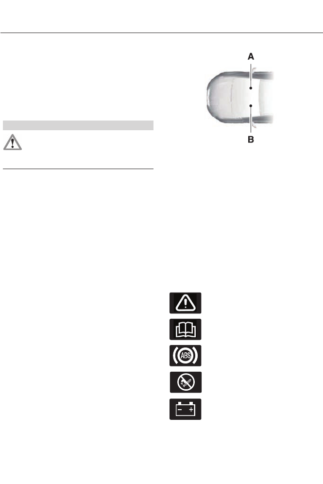
E154903
Right-hand sideA
Left-hand sideB
Protecting the Environment
You must play your part in protecting the
environment. Correct vehicle usage and
the authorized disposal of waste, cleaning
and lubrication materials are significant
steps toward this aim.
SYMBOLS GLOSSARY
These are some of the symbols you may
see on your vehicle.
Safety alert
See Owner's Manual
Anti-lock braking system
Avoid smoking, flames or sparks
Battery
7
Introduction
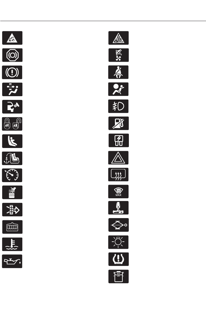
Battery acid
Brake fluid - non petroleum
based
Brake system
Cabin air filter
Check fuel cap
Child safety door lock or unlock
Child seat lower anchor
Child seat tether anchor
E71340
Cruise control
Do not open when hot
Engine air filter
Engine coolant
Engine coolant temperature
Engine oil
Explosive gas
Fan warning
Fasten safety belt
Front airbag
Front fog lamps
Fuel pump reset
Fuse compartment
Hazard warning flashers
Heated rear window
E91392
Heated windshield
Interior luggage compartment
release
Jack
Lighting control
Low tire pressure warning
Maintain correct fluid level
8
Introduction
Panic alarm
E139213
Parking aid
Parking brake
Power steering fluid
Power windows front/rear
Power window lockout
Service engine soon
Side airbag
Stability control
Windshield wash and wipe
E162384
Air conditioning system
DATA RECORDING
Service Data Recording
Service data recorders in your vehicle are
capable of collecting and storing
diagnostic information about your vehicle.
This potentially includes information about
the performance or status of various
systems and modules in the vehicle, such
as engine, throttle, steering or brake
systems. In order to properly diagnose and
service your vehicle, Ford Motor Company,
Ford of Canada, and service and repair
facilities may access or share among them
vehicle diagnostic information received
through a direct connection to your vehicle
when diagnosing or servicing your vehicle.
Additionally, when your vehicle is in for
service or repair, Ford Motor Company,
Ford of Canada, and service and repair
facilities may access or share among them
data for vehicle improvement purposes.
For U.S. only (if equipped), if you choose
to use the SYNC Vehicle Health Report,
you consent that certain diagnostic
information may also be accessed
electronically by Ford Motor Company and
Ford authorized service facilities, and that
the diagnostic information may be used
for any purpose. See SYNC™ (page 310).
Event Data Recording
This vehicle is equipped with an event
data recorder. The main purpose of an
event data recorder is to record, in
certain crash or near crash-like
situations, such as an airbag
deployment or hitting a road obstacle;
this data will assist in understanding
how a vehicle’s systems performed.
The event data recorder is designed to
record data related to vehicle dynamics
and safety systems for a short period
of time, typically 30 seconds or less.
The event data recorder in this vehicle
is designed to record such data as:
•How various systems in your vehicle
were operating;
•Whether or not the driver and
passenger safety belts were
buckled/fastened;
•How far (if at all) the driver was
depressing the accelerator and/or
the brake pedal; and
9
Introduction

•How fast the vehicle was travelling;
and
•Where the driver was positioning
the steering wheel.
This data can help provide a better
understanding of the circumstances in
which crashes and injuries occur.
Note: Event data recorder data is
recorded by your vehicle only if a
non-trivial crash situation occurs; no data
is recorded by the event data recorder
under normal driving conditions and no
personal data or information (e.g., name,
gender, age, and crash location) is
recorded (see limitations regarding 911
Assist and Traffic, directions and
Information privacy below). However,
parties, such as law enforcement, could
combine the event data recorder data
with the type of personally identifying
data routinely acquired during a crash
investigation.
To read data recorded by an event data
recorder, special equipment is required,
and access to the vehicle or the event
data recorder is needed. In addition to
the vehicle manufacturer, other
parties, such as law enforcement, that
have such special equipment, can read
the information if they have access to
the vehicle or the event data recorder.
Ford Motor Company and Ford of
Canada do not access event data
recorder information without obtaining
consent, unless pursuant to court order
or where required by law enforcement,
other government authorities or other
third parties acting with lawful
authority. Other parties may seek to
access the information independently
of Ford Motor Company and Ford of
Canada.
Note: Including to the extent that any
law pertaining to Event Data Recorders
applies to SYNC or its features, please
note the following: Once 911 Assist (if
equipped) is enabled (set ON), 911 Assist
may, through any paired and connected
cell phone, disclose to emergency
services that the vehicle has been in a
crash involving the deployment of an
airbag or, in certain vehicles, the
activation of the fuel pump shut-off.
Certain versions or updates to 911 Assist
may also be capable of being used to
electronically or verbally provide to 911
operators the vehicle location (such as
latitude and longitude), and/or other
details about the vehicle or crash or
personal information about the
occupants to assist 911 operators to
provide the most appropriate emergency
services. If you do not want to disclose
this information, do not activate the 911
Assist feature. See SYNC™ (page 310).
Additionally, when you connect to
Traffic, Directions and Information (if
equipped, U.S. only), the service uses
GPS technology and advanced vehicle
sensors to collect the vehicle’s current
location, travel direction, and speed
(“vehicle travel information”), only to
help provide you with the directions,
traffic reports, or business searches
that you request. If you do not want
Ford or its vendors to receive this
information, do not activate the
service. Ford Motor Company and the
vendors it uses to provide you with this
information do not store your vehicle
travel information. For more
information, see Traffic, Directions and
Information, Terms and Conditions.
See SYNC™ (page 310).
10
Introduction
CALIFORNIA PROPOSITION 65
WARNING
Some constituents of engine
exhaust, certain vehicle components,
certain fluids contained in vehicles
and certain products of component wear
contain or emit chemicals known to the
State of California to cause cancer and
birth defects or other reproductive harm.
PERCHLORATE
Certain components in your vehicle such
as airbag modules, safety belt
pretensioners and remote control batteries
may contain perchlorate material. Special
handling may apply for service or vehicle
end of life disposal. For more information
visit:
Web Address
www.dtsc.ca.gov/hazardouswaste/
perchlorate
FORD CREDIT
(U.S. Only)
Ford Credit offers a full range of financing
and lease plans to help you acquire your
vehicle. If you have financed or leased your
vehicle through Ford Credit, thank you for
your business.
For your convenience we offer a number
of ways to contact us, as well as help
manage your account.
Phone: 1-800-727-7000
For more information regarding Ford Credit,
as well as access Account Manager, please
go to www.fordcredit.com.
REPLACEMENT PARTS
RECOMMENDATION
Your vehicle has been built to the highest
standards using quality parts. We
recommend that you demand the use of
genuine Ford and Motorcraft parts
whenever your vehicle requires scheduled
maintenance or repair. You can clearly
identify genuine Ford and Motorcraft parts
by looking for the Ford, FoMoCo or
Motorcraft branding on the parts or their
packaging.
Scheduled Maintenance and
Mechanical Repairs
One of the best ways for you to make sure
that your vehicle provides years of service
is to have it maintained in line with our
recommendations using parts that
conform to the specifications detailed in
this Owner’s Manual. Genuine Ford and
Motorcraft parts meet or exceed these
specifications.
Collision Repairs
We hope that you never experience a
collision, but accidents do happen. Genuine
Ford replacement collision parts meet our
stringent requirements for fit, finish,
structural integrity, corrosion protection
and dent resistance. During vehicle
development we validate these parts
deliver the intended level of protection as
a whole system. A great way to know for
sure you are getting this level of protection
is to use genuine Ford replacement
collision parts.
11
Introduction
Warranty on Replacement Parts
Genuine Ford and Motorcraft replacement
parts are the only replacement parts that
benefit from a Ford Warranty. Damage
caused to your vehicle as a result of the
failure of non-Ford parts may not be
covered by the Ford Warranty. For
additional information, refer to the terms
and conditions of the Ford Warranty.
SPECIAL NOTICES
New Vehicle Limited Warranty
For a detailed description of what is
covered and what is not covered by your
vehicle’s New Vehicle Limited Warranty,
refer to the Warranty Manual that is
provided to you along with your Owner’s
Manual.
Special Instructions
For your added safety, your vehicle is fitted
with sophisticated electronic controls.
WARNINGS
Failure to follow the specific
warnings and instructions could
result in personal injury. See
Supplementary Restraints System
(page 33).
Front seat mounted rear-facing child
or infant seats should NEVER be
placed in front of an active
passenger airbag.
MOBILE COMMUNICATIONS
EQUIPMENT
Using mobile communications equipment
is becoming increasingly important in the
conduct of business and personal affairs.
However, you must not compromise your
own or others’ safety when using such
equipment. Mobile communications can
enhance personal safety and security when
appropriately used, particularly in
emergency situations. Safety must be
paramount when using mobile
communications equipment to avoid
negating these benefits. Mobile
communication equipment includes, but
is not limited to, cellular phones, pagers,
portable email devices, text messaging
devices and portable two-way radios.
WARNING
Driving while distracted can result in
loss of vehicle control, crash and
injury. We strongly recommend that
you use extreme caution when using any
device that may take your focus off the
road. Your primary responsibility is the safe
operation of your vehicle. We recommend
against the use of any hand-held device
while driving and encourage the use of
voice-operated systems when possible.
Make sure you are aware of all applicable
local laws that may affect the use of
electronic devices while driving.
EXPORT UNIQUE OPTIONS
For your particular global region, your
vehicle may be equipped with features and
options that are different from the features
and options that are described in this
Owner’s Manual. A market unique
supplement may be supplied that
complements this book. By referring to the
market unique supplement, if provided,
you can properly identify those features,
recommendations and specifications that
are unique to your vehicle. This Owner’s
Manual is written primarily for the U.S. and
Canadian Markets. Features or equipment
listed as standard may be different on units
built for Export. Refer to this Owner’s
Manual for all other required
information and warnings.
12
Introduction

GENERAL INFORMATION
See the following sections for directions
on how to properly use safety restraints
for children.
WARNINGS
Always make sure your child is
secured properly in a device that is
appropriate for their height, age and
weight. Child safety restraints must be
bought separately from your vehicle.
Failure to follow these instructions and
guidelines may result in an increased risk
of serious injury or death to your child.
All children are shaped differently.
The recommendations for safety
restraints are based on probable
child height, age and weight thresholds
from National Highway Traffic Safety
Administration and other safety
organizations, or are the minimum
WARNINGS
requirements of law. Ford recommends
checking with a NHTSA Certified Child
Passenger Safety Technician (CPST) and
consult your pediatrician to make sure your
child seat is appropriate for your child, and
is compatible with and properly installed
in your vehicle. To locate a child seat fitting
station and CPST, contact the NHTSA toll
free at 1-888-327-4236 or go to
www.nhtsa.gov. In Canada, check with
your local St. John Ambulance office for
referral to a CPST or for further
information, contact your provincial
ministry of transportation, locate your local
St. John Ambulance office by searching for
St. John Ambulance on the internet, or
Transport Canada at 1-800-333-0371
(http://www.tc.gc.ca). Failure to properly
restrain children in safety seats made
especially for their height, age, and weight
may result in an increased risk of serious
injury or death to your child.
13
Child Safety

Recommendations for Safety Restraints for Children
Recommended restraint
type
Child size, height, weight, or ageChild
Use a child safety seat
(sometimes called an
infant carrier, convertible
seat, or toddler seat).
Children weighing 40 lb (18 kg) or less
(generally age four or younger).
Infants or
toddlers
Use a belt-positioning
booster seat.
Children who have outgrown or no longer
properly fit in a child safety seat (gener-
ally children who are less than 4 ft. 9 in.
(1.45 m) tall, are greater than age four
and less than age 12, and between 40 lb
(18 kg) and 80 lb (36 kg) and upward to
100 lb (45 kg) if recommended by your
child restraint manufacturer).
Small children
Use a vehicle safety belt
having the lap belt snug
and low across the hips,
shoulder belt centered
across the shoulder and
chest, and seat back
upright.
Children who have outgrown or no longer
properly fit in a belt-positioning booster
seat (generally children who are at least
4 ft. 9 in. (1.45 m) tall or greater than 80
lb (36 kg) or 100 lb (45 kg) if recom-
mended by child restraint manufacturer).
Larger children
• You are required by law to properly use
safety seats for infants and toddlers in
the United States and Canada.
• Many states and provinces require that
small children use approved booster
seats until they reach age eight, a
height of 4 feet 9 inches (1.45 meters)
tall, or 80 pounds (36 kilograms).
Check your local and state or provincial
laws for specific requirements about
the safety of children in your vehicle.
• When possible, always properly
restrain children 12 years of age and
under in a rear seating position of your
vehicle. Accident statistics suggest that
children are safer when properly
restrained in the rear seating positions
than in a front seating position. See
Front Passenger Sensing System
(page 36).
CHILD SEAT POSITIONING
WARNINGS
Airbags can kill or injure a child in a
child seat. Never place a rear-facing
child seat in front of an active airbag.
If you must use a forward-facing child seat
in the front seat, move the vehicle seat
upon which the child seat is installed all
the way back. When possible, all children
age 12 and under should be properly
restrained in a rear seating position. If all
children cannot be seated and restrained
properly in a rear seating position, properly
restrain the largest child in the front seat.
14
Child Safety
WARNINGS
Always carefully follow the
instructions and warnings provided
by the manufacturer of any child
restraint to determine if the restraint device
is appropriate for your child's size, height,
weight, or age. Follow the child restraint
manufacturer's instructions and warnings
provided for installation and use in
conjunction with the instructions and
warnings provided by your vehicle
manufacturer. A safety seat that is
improperly installed or utilized, is
inappropriate for your child's height, age,
or weight or does not properly fit the child
may increase the risk of serious injury or
death.
Never let a passenger hold a child on
his or her lap while your vehicle is
moving. The passenger cannot
protect the child from injury in a crash,
which may result in serious injury or death.
WARNINGS
Never use pillows, books, or towels
to boost a child. They can slide
around and increase the likelihood
of injury or death in a crash.
Always restrain an unoccupied child
seat or booster seat. These objects
may become projectiles in a crash or
sudden stop, which may increase the risk
of serious injury.
Never place, or allow a child to place,
the shoulder belt under a child's arm
or behind the back because it
reduces the protection for the upper part
of the body and may increase the risk of
injury or death in a crash.
To avoid risk of injury, do not leave
children or pets unattended in your
vehicle.
Use any attachment method as indicated below by XCombined
child and
seat
weight
Restraint
Type Safety belt
only
Safety belt
and LATCH
(lower
anchors
and top
tether
anchor)
Safety belt
and top
tether
anchor
LATCH
(lower
anchors
only)
LATCH
(lower
anchors
and top
tether
anchor)
XXUp to 65 lb
(29 kg)
Rear facing
child seat
XOver 65 lb
(29 kg)
Rear facing
child seat
XXXUp to 65 lb
(29 kg)
Forward
facing
child seat
XXOver 65 lb
(29 kg)
Forward
facing
child seat
15
Child Safety
Note: The child seat must rest tightly
against the vehicle seat upon which it is
installed. It may be necessary to lift or
remove the head restraint. See Seats (page
117).
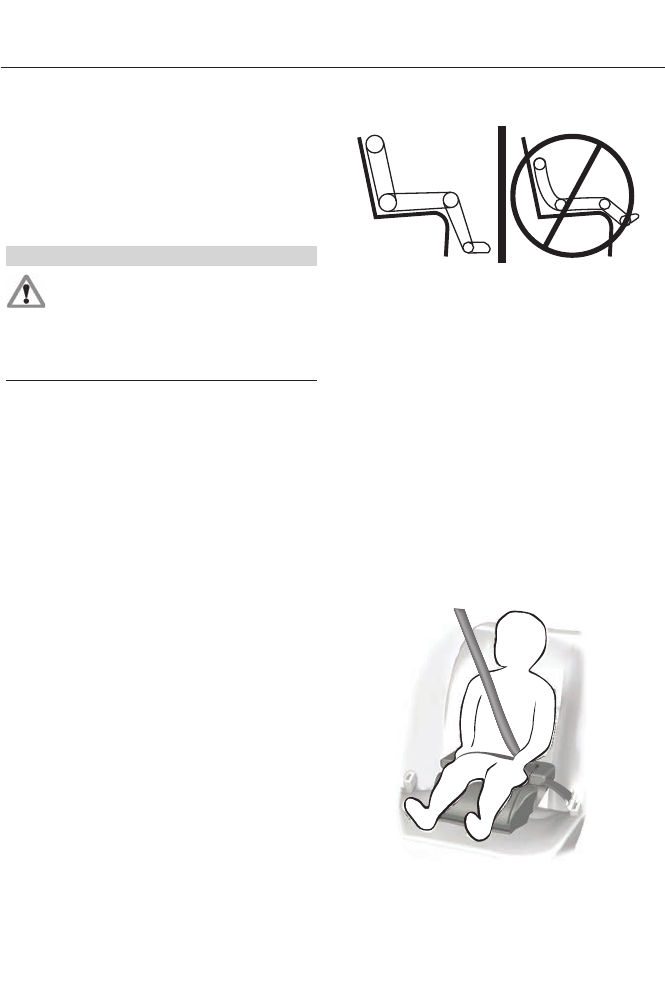
BOOSTER SEATS
WARNING
Never place, or allow a child to place,
the shoulder belt under a child's arm
or behind the back because it
reduces the protection for the upper part
of the body and may increase the risk of
injury or death in a crash.
Use a belt-positioning booster seat for
children who have outgrown or no longer
properly fit in a child safety seat (generally
children who are less than 4 feet 9 inches
(1.45 meters) tall, are greater than age four
(4) and less than age twelve (12), and
between 40 pounds (18 kilograms) and
80 pounds (36 kilograms) and upward to
100 pounds (45 kilograms) if
recommended by your child restraint
manufacturer). Many state and provincial
laws require that children use approved
booster seats until they reach age eight, a
height of 4 feet 9 inches (1.45 meters) tall,
or 80 pounds (36 kilograms).
Booster seats should be used until you can
answer YES to ALL of these questions
when seated without a booster seat:
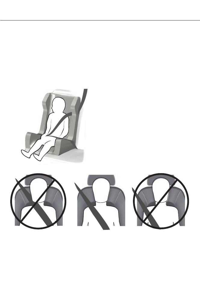
E142595
• Can the child sit all the way back
against their vehicle seat back with
knees bent comfortably at the edge of
the seat cushion?
• Can the child sit without slouching?
• Does the lap belt rest low across the
hips?
• Is the shoulder belt centered on the
shoulder and chest?
• Can the child stay seated like this for
the whole trip?
Always use booster seats in conjunction
with your vehicle lap and shoulder belt.
Types of Booster Seats
E68924
• Backless booster seats
16
Child Safety
If your backless booster seat has a
removable shield, remove the shield. If a
vehicle seating position has a low seat
back or no head restraint, a backless
booster seat may place your child's head
(as measured at the tops of the ears)
above the top of the seat. In this case,
move the backless booster to another
seating position with a higher seat back or
head restraint and lap and shoulder belts,
or consider using a high back booster seat.
E70710
• High back booster seats
If, with a backless booster seat, you cannot
find a seating position that adequately
supports your child's head, a high back
booster seat would be a better choice.
Children and booster seats vary in size and
shape. Choose a booster that keeps the
lap belt low and snug across the hips,
never up across the stomach, and lets you
adjust the shoulder belt to cross the chest
and rest snugly near the center of the
shoulder. The following drawings compare
the ideal fit (center) to a shoulder belt
uncomfortably close to the neck and a
shoulder belt that could slip off the
shoulder. The drawings also show how the
lap belt should be low and snug across the
child's hips.
E142596
17
Child Safety
E142597
If the booster seat slides on the vehicle
seat upon which it is being used, placing a
rubberized mesh sold as shelf or carpet
liner under the booster seat may improve
this condition. Do not introduce any item
thicker than this under the booster seat.
Check with the booster seat
manufacturer's instructions.
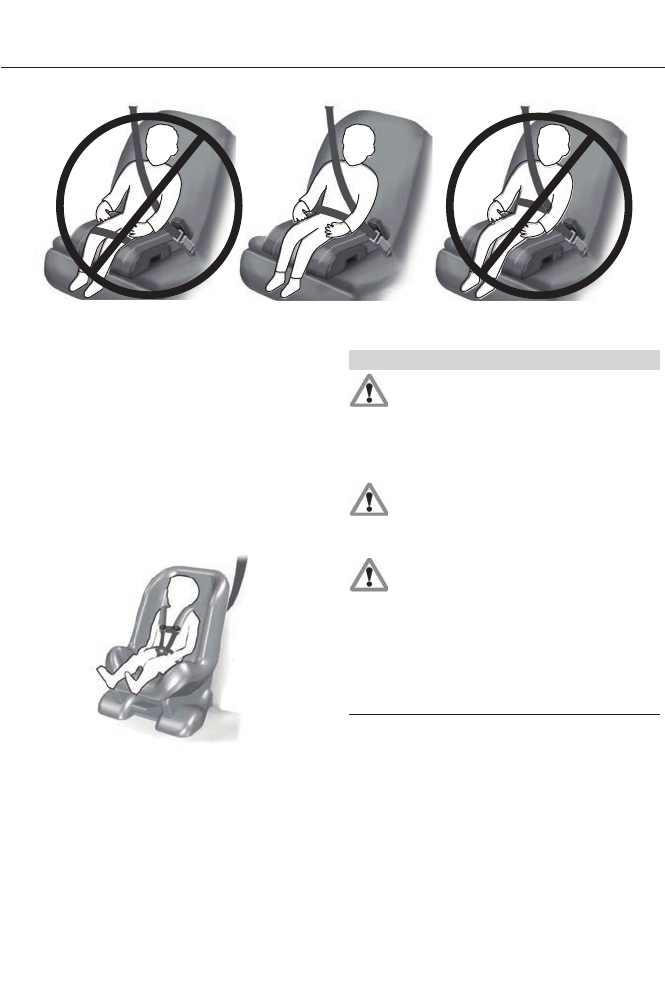
INSTALLING CHILD SEATS
Child Seats
E142594
Use a child safety seat (sometimes called
an infant carrier, convertible seat, or
toddler seat) for infants, toddlers, or
children weighing 40 pounds (18
kilograms) or less (generally age four or
younger).
Using Lap and Shoulder Belts
WARNINGS
Airbags can kill or injure a child in a
child seat. Never place a rear-facing
child seat in front of an active airbag.
If you must use a forward-facing child seat
in the front seat, move the seat all the way
back.
Airbags can kill or injure a child in a
child seat. Children 12 and under
should be properly restrained in the
rear seat whenever possible.
Depending on where you secure a
child restraint, and depending on the
child restraint design, you may block
access to certain safety belt buckle
assemblies and LATCH lower anchors,
rendering those features potentially
unusable. To avoid risk of injury, occupants
should only use seating positions where
they are able to be properly restrained.
When installing a child safety seat with
combination lap and shoulder belts:
• Use the correct safety belt buckle for
that seating position.
• Insert the belt tongue into the proper
buckle until you hear a snap and feel it
latch. Make sure the tongue is securely
fastened in the buckle.
18
Child Safety
• Keep the buckle release button
pointing up and away from the safety
seat, with the tongue between the child
seat and the release button, to prevent
accidental unbuckling.
• Place the vehicle seat upon which the
child seat will be installed in the upright
position.
• Put the safety belt in the automatic
locking mode. See Step 5. This vehicle
does not require the use of a locking
clip.
Perform the following steps when
installing the child seat with combination
lap and shoulder belts:
Note: Although the child seat illustrated is
a forward facing child seat, the steps are
the same for installing a rear facing child
seat.
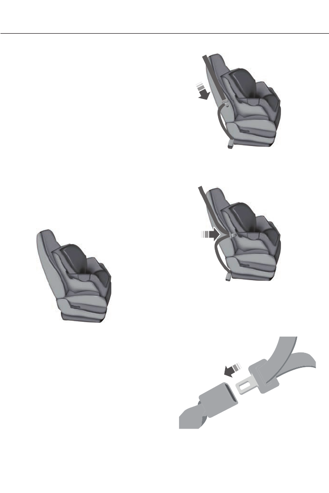
E142528
1. Position the child safety seat in a seat
with a combination lap and shoulder
belt.
E142529
2. Pull down on the shoulder belt and
then grasp the shoulder belt and lap
belt together.
E142530
3. While holding the shoulder and lap belt
portions together, route the tongue
through the child seat according to the
child seat manufacturer's instructions.
Be sure the belt webbing is not twisted.
E142531
19
Child Safety
4. Insert the belt tongue into the proper
buckle (the buckle closest to the
direction the tongue is coming from)
for that seating position until you hear
a snap and feel the latch engage. Make
sure the tongue is latched securely by
pulling on it.
E142875
5. To put the retractor in the automatic
locking mode, grasp the shoulder
portion of the belt and pull downward
until all of the belt is pulled out.
Note: The automatic locking mode is
available on the front passenger and rear
seats. This vehicle does not require the use
of a locking clip.
6. Allow the belt to retract to remove
slack. The belt will click as it retracts
to indicate it is in the automatic locking
mode.
7. Try to pull the belt out of the retractor
to make sure the retractor is in the
automatic locking mode (you should
not be able to pull more belt out). If the
retractor is not locked, unbuckle the
belt and repeat Steps 5 and 6.
E142533
8. Remove remaining slack from the belt.
Force the seat down with extra weight,
for example, by pressing down or
kneeling on the child restraint while
pulling up on the shoulder belt in order
to force slack from the belt. This is
necessary to remove the remaining
slack that will exist once the extra
weight of the child is added to the child
restraint. It also helps to achieve the
proper snugness of the child seat to
your vehicle. Sometimes, a slight lean
toward the buckle will additionally help
to remove remaining slack from the
belt.
9. Attach the tether strap (if the child seat
is equipped).
E142534
20
Child Safety
10. Before placing the child in the seat,
forcibly move the seat forward and
back to make sure the seat is securely
held in place. To check this, grab the
seat at the belt path and attempt to
move it side to side and forward and
back. There should be no more than
1 inch (2.5 centimeters) of movement
for proper installation.
Ford recommends checking with a NHTSA
Certified Child Passenger Safety
Technician to make certain the child
restraint is properly installed. In Canada,
check with your local St. John Ambulance
office for referral to a Certified Passenger
Seat Technician.
Using Lower Anchors and Tethers
for CHildren (LATCH)
WARNINGS
Never attach two child safety seats
to the same anchor. In a crash, one
anchor may not be strong enough to
hold two child safety seat attachments
and may break, causing serious injury or
death.
Depending on where you secure a
child restraint, and depending on the
child restraint design, you may block
access to certain safety belt buckle
assemblies or LATCH lower anchors,
rendering those features potentially
unusable. To avoid risk of injury, occupants
should only use seating positions where
they are able to be properly restrained.
The LATCH system is composed of three
vehicle anchor points: two lower anchors
located where seat back and seat cushion
meet (called the seat bight) and one top
tether anchor located behind that seating
position.
LATCH compatible child safety seats have
two rigid or webbing mounted
attachments that connect to the two lower
anchors at the LATCH equipped seating
positions in your vehicle. This type of
attachment method eliminates the need
to use safety belts to attach the child seat,
however the safety belt can still be used
to attach the child seat. For forward-facing
child seats, the top tether strap must also
be attached to the proper top tether
anchor, if a top tether strap has been
provided with your child seat.
E142535
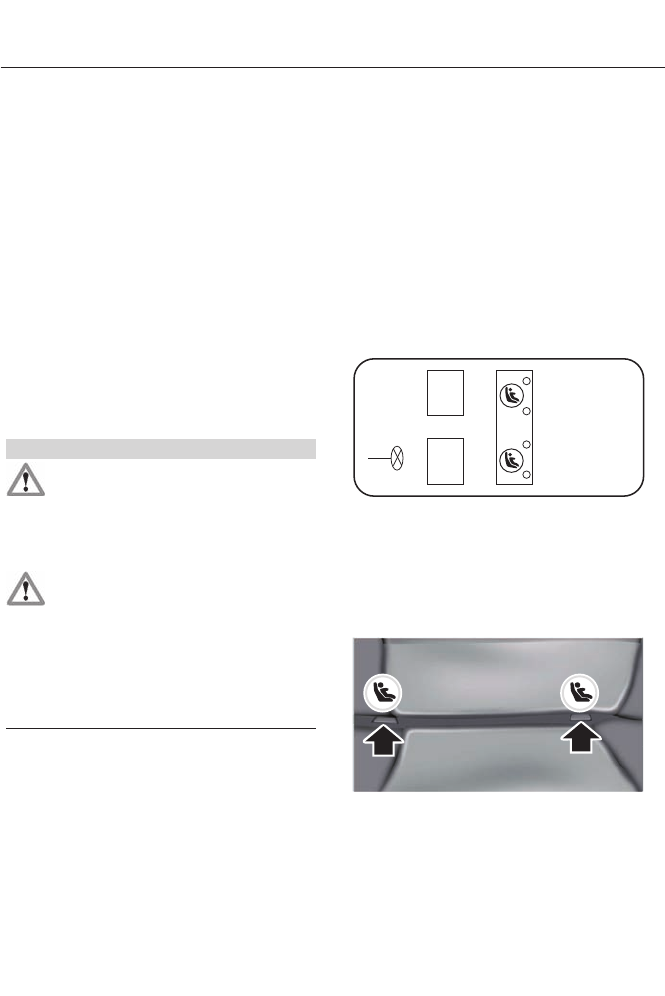
Your vehicle has LATCH lower anchors for
child seat installation at the seating
positions marked with the child seat
symbol.
E144054
21
Child Safety

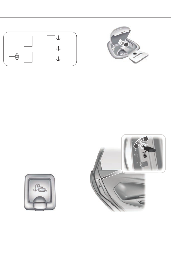
The LATCH anchors are located at the rear
section of the rear seat between the
cushion and seat back below the symbols
as shown. Follow the child seat
manufacturer's instructions to properly
install a child seat with LATCH
attachments. Follow the instructions on
attaching child safety seats with tether
straps.
Attach LATCH lower attachments of the
child seat only to the anchors shown.
Use of Inboard Lower Anchors from the
Outboard Seating Positions (Center
Seating Use)
Note: The standardized spacing for LATCH
lower anchors is 11 inches (28 centimeters)
center to center. Do not use LATCH lower
anchors for the center seating position
unless the child seat manufacturer's
instructions permit and specify using
anchors spaced at least as far apart as
those in this vehicle.
The lower anchors at the center of the
second row rear seat are spaced 18 inches
(46 centimeters) apart. A child seat with
rigid LATCH attachments cannot be
installed at the center seating position.
LATCH compatible child seats (with
attachments on belt webbing) can only be
used at this seating position provided that
the child seat manufacturer's instructions
permit use with the anchor spacing stated.
Do not attach a child seat to any lower
anchor if an adjacent child seat is attached
to that anchor.
Each time you use the safety seat, check
that the seat is properly attached to the
lower anchors and tether anchor, if
applicable. Tug the child seat from side to
side and forward and back where it is
secured to your vehicle. The seat should
move less than one inch when you do this
for a proper installation.
If the safety seat is not anchored properly,
the risk of a child being injured in a crash
greatly increases.
Combining Safety Belt and LATCH
Lower Anchors for Attaching Child
Safety Seats
When used in combination, either the
safety belt or the LATCH lower anchors
may be attached first, provided a proper
installation is achieved. Attach the tether
strap afterward, if included with the child
seat.
Using Tether Straps
Many forward-facing child safety
seats include a tether strap
which extends from the back of
the child safety seat and hooks to an
anchoring point called the top tether
anchor. Tether straps are available as an
accessory for many older safety seats.
Contact the manufacturer of your child
seat for information about ordering a
tether strap, or to obtain a longer tether
strap if the tether strap on your safety seat
does not reach the appropriate top tether
anchor in your vehicle.
Once the child safety seat has been
installed using either the safety belt, the
lower anchors of the LATCH system, or
both, you can attach the top tether strap.
The tether strap anchors in your vehicle
are in the following positions (shown from
top view):
22
Child Safety
E142537
Perform the following steps to install a
child safety seat with tether anchors:
Note: If you install a child seat with rigid
LATCH attachments, do not tighten the
tether strap enough to lift the child seat off
your vehicle seat cushion when the child is
seated in it. Keep the tether strap just snug
without lifting the front of the child seat.
Keeping the child seat just touching your
vehicle seat gives the best protection in a
severe crash.
1. Route the child safety seat tether strap
over the back of the seat. For outboard
seating positions, route the tether strap
under the head restraint and between
the head restraint posts. For the center
seating positions, route the tether strap
over the top of the head restraint. If
needed, the head restraints can also
be removed.
E144274
2. Locate the correct anchor for the
selected seating position, then open
the tether anchor cover.
E144275
3. Clip the tether strap to the anchor as
shown.
4. Tighten the child safety seat tether
strap according to the manufacturer's
instructions. If your child restraint
system is equipped with a tether strap,
and the child restraint manufacturer
recommends its use, Ford also
recommends its use.
CHILD SAFETY LOCKS
When these locks are set, the rear doors
cannot be opened from the inside.
E112197
The childproof locks are located on the
rear edge of each rear door and must be
set separately for each door.
23
Child Safety

Left-Hand Side
Turn counterclockwise to lock and
clockwise to unlock.
Right-Hand Side
Turn clockwise to lock and
counterclockwise to unlock.
24
Child Safety
PRINCIPLE OF OPERATION
WARNINGS
Always drive and ride with your seat
back upright and the lap belt snug
and low across the hips.
To reduce the risk of injury, make
sure children sit where they can be
properly restrained.
Never let a passenger hold a child on
his or her lap while the vehicle is
moving. The passenger cannot
protect the child from injury in a crash.
All occupants of the vehicle,
including the driver, should always
properly wear their safety belts, even
when an airbag supplemental restraint
system is provided. Failure to properly wear
your safety belt could seriously increase
the risk of injury or death.
It is extremely dangerous to ride in a
cargo area, inside or outside of a
vehicle. In a crash, people riding in
these areas are more likely to be seriously
injured or killed. Do not allow people to ride
in any area of your vehicle that is not
equipped with seats and safety belts. Be
sure everyone in your vehicle is in a seat
and using a safety belt properly.
In a rollover crash, an unbelted
person is significantly more likely to
die than a person wearing a safety
belt.
Each seating position in your vehicle
has a specific safety belt assembly
which is made up of one buckle and
one tongue that are designed to be used
as a pair. 1) Use the shoulder belt on the
outside shoulder only. Never wear the
shoulder belt under the arm. 2) Never
swing the safety belt around your neck over
the inside shoulder. 3) Never use a single
belt for more than one person.
WARNINGS
When possible, all children 12 years
old and under should be properly
restrained in a rear seating position.
Failure to follow this could seriously
increase the risk of injury or death.
Safety belts and seats can become
hot in a vehicle that has been closed
up in sunny weather; they could burn
a small child. Check seat covers and
buckles before you place a child anywhere
near them.
Front and rear seat occupants,
including pregnant women, should
wear safety belts for optimum
protection in an accident.
All seating positions in this vehicle have
lap and shoulder safety belts. All
occupants of the vehicle should always
properly wear their safety belts, even when
an airbag supplemental restraint system
is provided.
The safety belt system consists of:
• lap and shoulder safety belts.
• shoulder safety belt with automatic
locking mode, (except driver safety
belt).
• height adjuster at the front outboard
seating positions.
• safety belt pretensioner at the front
outboard seating positions.
• belt tension sensor at the front
outboard passenger seating position.
• Safety belt warning light and chime.
25
Safety Belts
• Crash sensors and monitoring system
with readiness indicator.
The safety belt pretensioners at the front
seating positions are designed to tighten
the safety belts when activated. In frontal
and near-frontal crashes, the safety belt
pretensioners may be activated alone or,
if the crash is of sufficient severity, together
with the front airbags. The pretensioners
may also activate when a side curtain
airbag is deployed.
FASTENING THE SAFETY
BELTS
The front outboard and rear safety
restraints in the vehicle are combination
lap and shoulder belts.
E142587
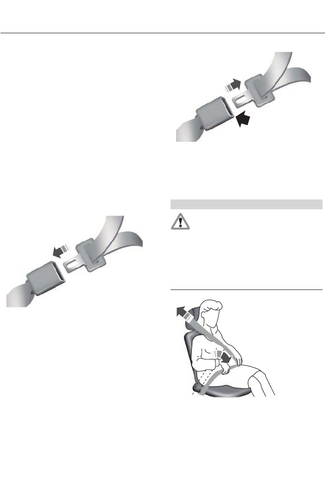
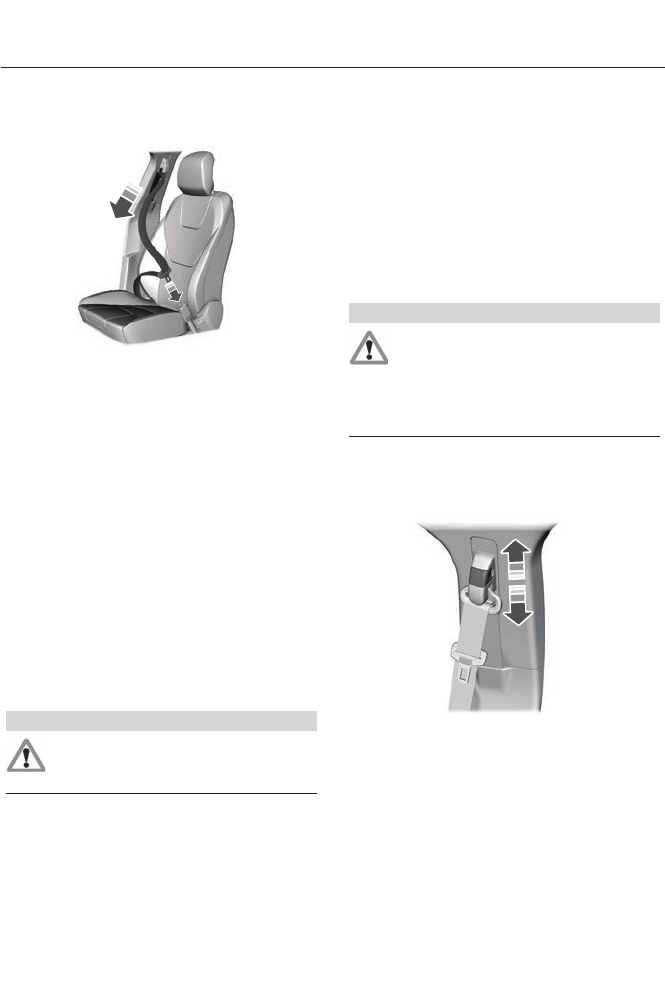
1. Insert the belt tongue into the proper
buckle (the buckle closest to the
direction the tongue is coming from)
until you hear a snap and feel it latch.
Make sure the tongue is securely
fastened in the buckle.
E142588
2. To unfasten, press the release button
and remove the tongue from the
buckle.
Restraint of Pregnant Women
WARNING
Always ride and drive with your
seatback upright and the safety belt
properly fastened. The lap portion of
the safety belt should fit snug and be
positioned low across the hips. The
shoulder portion of the safety belt should
be positioned across the chest. Pregnant
women should also follow this practice.
See the following figure.
E142590
26
Safety Belts
Pregnant women should always wear their
safety belt. The lap belt portion of a
combination lap and shoulder belt should
be positioned low across the hips below
the belly and worn as tight as comfort will
allow. The shoulder belt should be
positioned to cross the middle of the
shoulder and the center of the chest.
Safety Belt Locking Modes
WARNINGS
After any vehicle collision, the safety
belt system at all passenger seating
positions must be checked by an
authorized dealer to verify that the
automatic locking retractor feature for
child seats is still functioning properly. In
addition, all safety belts should be checked
for proper function.
BELT AND RETRACTOR ASSEMBLY
MUST BE REPLACED if the safety
belt assembly automatic locking
retractor feature or any other safety belt
function is not operating properly when
checked by an authorized dealer. Failure
to replace the belt and retractor assembly
could increase the risk of injury in collisions.
All safety restraints in the vehicle are
combination lap and shoulder belts. The
driver safety belt has the first type of
locking mode, and the front outboard
passenger and rear seat safety belts have
both types of locking modes described as
follows:
Vehicle Sensitive Mode
This is the normal retractor mode, which
allows free shoulder belt length
adjustment to your movements and
locking in response to vehicle movement.
For example, if the driver brakes suddenly
or turns a corner sharply, or the vehicle
receives an impact of approximately 5 mph
(8 km/h) or more, the combination safety
belts will lock to help reduce forward
movement of the driver and passengers.
In addition, the retractor is designed to lock
if the webbing is pulled out too quickly. If
this occurs, let the belt retract slightly and
pull webbing out again in a slow and
controlled manner.
Automatic Locking Mode
In this mode, the shoulder belt is
automatically pre-locked. The belt will still
retract to remove any slack in the shoulder
belt. The automatic locking mode is not
available on the driver safety belt.
When to Use the Automatic Locking
Mode
This mode should be used any time a child
safety seat, except a booster, is installed
in passenger front or rear seating positions.
Children 12 years old and under should be
properly restrained in a rear seating
position whenever possible. See Child
Safety (page 13).
27
Safety Belts
How to Use the Automatic Locking
Mode
E142591
1. Buckle the combination lap and
shoulder belt.
2. Grasp the shoulder portion and pull
downward until the entire belt is pulled
out.
Allow the belt to retract. As the belt
retracts, you will hear a clicking sound. This
indicates the safety belt is now in the
automatic locking mode.
How to Disengage the Automatic
Locking Mode
Disconnect the combination lap and
shoulder belt and allow it to retract
completely to disengage the automatic
locking mode and activate the vehicle
sensitive (emergency) locking mode.
Safety Belt Extension Assembly
WARNING
Do not use extensions to change the
fit of the shoulder belt across the
torso.
If the safety belt is too short when fully
extended, a safety belt extension assembly
can be obtained from an authorized dealer.
Use only extensions manufactured by the
same supplier as the safety belt.
Manufacturer identification is located at
the end of the webbing on the label. Also,
use the safety belt extension only if the
safety belt is too short for you when fully
extended.
SAFETY BELT HEIGHT
ADJUSTMENT
WARNING
Position the safety belt height
adjuster so that the belt rests across
the middle of your shoulder. Failure
to adjust the safety belt properly could
reduce the effectiveness of the safety belt
and increase the risk of injury in a crash.
Adjust the height of the shoulder belt so
the belt rests across the middle of your
shoulder.
E145664
To adjust the shoulder belt height:
1. Pull the button and slide the height
adjuster up or down.
2. Release the button and pull down on
the height adjuster to make sure it is
locked in place.
28
Safety Belts

SAFETY BELT WARNING LAMP
AND INDICATOR CHIME
This lamp illuminates and an
audible warning will sound if the
driver's safety belt has not been
fastened when the vehicle's ignition is
turned on.
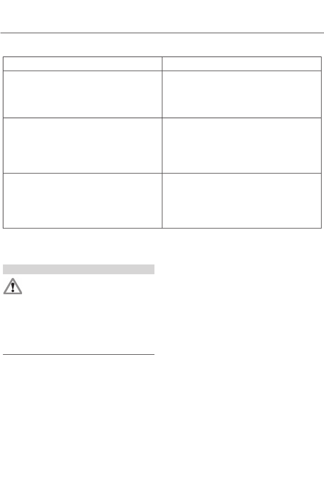
Conditions of operation
Then...If...
The safety belt warning light illuminates 1-
2 minutes and the warning chime sounds
4-8 seconds.
The driver's safety belt is not buckled
before the ignition switch is turned to the
on position...
The safety belt warning light and warning
chime turn off.
The driver's safety belt is buckled while the
indicator light is illuminated and the
warning chime is sounding...
The safety belt warning light and indicator
chime remain off.
The driver's safety belt is buckled before
the ignition switch is turned to the on posi-
tion...
SAFETY BELT MINDER
Belt-Minder®
This feature supplements the safety belt
warning function by providing additional
reminders by intermittently sounding a
chime and illuminating the safety belt
warning light when the driver's or front
passenger's seat is occupied and the
safety belt is unbuckled.
The system uses information from the
front passenger sensing system to
determine if a front seat passenger is
present and therefore potentially in need
of a warning. To avoid activating the
Belt-Minder feature for objects placed in
the front passenger seat, warnings will only
be given to front seat occupants as
determined by the front passenger sensing
system.
If the Belt-Minder warnings have expired
(warnings for about five minutes) for one
occupant (driver or front passenger), the
other occupant can still activate the
Belt-Minder feature.
29
Safety Belts
Then...If...
The Belt-Minder feature will not activate.The driver's and front passenger's safety
belts are buckled before the ignition switch
is turned to the on position or less than 1-2
minutes have elapsed since the ignition
switch has been turned to on...
The Belt-Minder feature is activated - the
safety belt warning light illuminates and
the warning chime sounds for six seconds
every 25 seconds, repeating for about five
minutes or until the safety belts are
buckled.
The driver's or front passenger's safety belt
is not buckled when the vehicle has reached
at least 6 mph (9.7 km/h) and 1-2 minutes
have elapsed since the ignition switch has
been turned to on...
The Belt-Minder feature is activated - the
safety belt warning light illuminates and
the warning chime sounds for six seconds
every 25 seconds, repeating for about five
minutes or until the safety belts are
buckled.
The driver's or front passenger's safety belt
becomes unbuckled for about one minute
while the vehicle is traveling at least 6 mph
(9.7 km/h) and more than 1-2 minutes have
elapsed since the ignition switch has been
turned to on...
Deactivating and Activating the
Belt-Minder Feature
WARNING
While the system allows you to
deactivate it, this system is designed
to improve your chances of being
safely belted and surviving an accident.
We recommend you leave the system
activated for yourself and others who may
use the vehicle. To reduce the risk of injury,
do not deactivate or activate the system
while driving the vehicle.
Note: The driver and front passenger
warning are deactivated and activated
independently. When deactivating or
activating one seating position, do not
buckle the other position as this will
terminate the process.
Read Steps 1 - 4 thoroughly before
proceeding with the programming
procedure.
The system can be deactivated or
activated by performing the following
procedure:
Before following the procedure, make sure
that:
• the parking brake is set
• the transmission selector lever is in
position P (automatic transmission)
or N (manual transmission)
• the ignition is off
• the driver and front passenger safety
belts are unbuckled.
1. Turn the ignition on. Do not start the
engine.
2. Wait until the safety belt warning light
turns off (about one minute). After
Step 2, wait an additional five seconds
before proceeding with Step 3. Once
Step 3 is started, the procedure must
be completed within 30 seconds.
30
Safety Belts

3. For the seating position being disabled,
buckle then unbuckle the safety belt
three times at a moderate speed,
ending in the unbuckled state. After
Step 3, the safety belt warning light will
turn on.
4. While the safety belt warning light is
on, buckle and then unbuckle the
safety belt. After Step 4, the safety belt
warning light will flash for confirmation.
• This will disable the feature for that
seating position if it is currently
enabled.
• This will enable the feature for that
seating position if it is currently
disabled.
CHILD RESTRAINT AND
SAFETY BELT MAINTENANCE
Inspect the vehicle safety belts and child
safety seat systems periodically to make
sure they work properly and are not
damaged. Inspect the vehicle and child
seat safety belts to make sure there are no
nicks, tears or cuts. Replace if necessary.
All vehicle safety belt assemblies, including
retractors, buckles, front safety belt buckle
assemblies, buckle support assemblies
(slide bar-if equipped), shoulder belt
height adjusters (if equipped), shoulder
belt guide on seat back (if equipped), child
safety seat LATCH and tether anchors, and
attaching hardware, should be inspected
after a crash. Read the child restraint
manufacturer's instructions for additional
inspection and maintenance information
specific to the child restraint.
Ford Motor Company recommends that
all safety belt assemblies in use in vehicles
involved in a crash be replaced. However,
if the crash was minor and an authorized
dealer finds that the belts do not show
damage and continue to operate properly,
they do not need to be replaced. Safety
belt assemblies not in use during a crash
should also be inspected and replaced if
either damage or improper operation is
noted.
Properly care for safety belts. See Vehicle
Care (page 253).
31
Safety Belts

The Personal Safety System provides an
improved overall level of frontal crash
protection to front seat occupants and is
designed to help further reduce the risk of
airbag-related injuries. The system is able
to analyze different occupant conditions
and crash severity before activating the
appropriate safety devices to help better
protect a range of occupants in a variety
of frontal crash situations.
Your vehicle's Personal Safety System
consists of:
• Driver and passenger dual-stage airbag
supplemental restraints.
• Front outboard safety belts with
pretensioners, energy management
retractors (first row only), and safety
belt usage sensors.
• Driver’s seat position sensor.
• Front passenger sensing system.
• Passenger airbag off and on indicator
lamp.
• Front crash severity sensors.
• Restraints control module with impact
and safing sensors.
• Restraint system warning light and
backup tone.
• The electrical wiring for the airbags,
crash sensor(s), safety belt
pretensioners, front safety belt usage
sensors, driver seat position sensor,
front passenger sensing system, and
indicator lights.
How Does the Personal Safety
System Work?
The Personal Safety System can adapt the
deployment strategy of your vehicle’s
safety devices according to crash severity
and occupant conditions. A collection of
crash and occupant sensors provides
information to the restraints control
module. During a crash, the restraints
control module may activate the safety
belt pretensioners and may activate either
one or both stages of the dual-stage airbag
supplemental restraints based on crash
severity and occupant conditions.
32
Personal Safety System™
PRINCIPLE OF OPERATION
WARNINGS
Airbags do not inflate slowly or
gently, and the risk of injury from a
deploying airbag is the greatest close
to the trim covering the airbag module.
All occupants of your vehicle,
including the driver, should always
properly wear their safety belts, even
when an airbag supplemental restraint
system is provided. Failure to properly wear
your safety belt could seriously increase
the risk of injury or death.
Always transport children 12 years
old and under in the back seat and
always properly use appropriate
child restraints. Failure to follow this could
seriously increase the risk of injury or death.
Never place your arm over the airbag
module as a deploying airbag can
result in serious arm fractures or
other injuries.
Airbags can kill or injure a child in a
child seat. Never place a rear-facing
child seat in front of an active airbag.
If you must use a forward-facing child seat
in the front seat, move the seat all the way
back.
Do not attempt to service, repair, or
modify the airbag supplemental
restraint systems or its fuses as you
could be seriously injured or killed. Contact
your authorized dealer as soon as possible.
Several airbag system components
get hot after inflation. To reduce the
risk of injury, do not touch them after
inflation.
If the airbag has deployed, the airbag
will not function again and must be
replaced immediately. If the airbag
is not replaced, the unrepaired area will
increase the risk of injury in a crash.
The airbags are a supplemental restraint
system and are designed to work with the
safety belts to help protect the driver and
right front passenger from certain upper
body injuries. Airbags do not inflate slowly;
there is a risk of injury from a deploying
airbag.
Note: You will hear a loud bang and see a
cloud of harmless powdery residue if an
airbag deploys. This is normal.
The airbags inflate and deflate rapidly
upon activation. After airbag deployment,
it is normal to notice a smoke-like, powdery
residue or smell the burnt propellant. This
may consist of cornstarch, talcum powder
(to lubricate the bag) or sodium
compounds (for example, baking soda)
that result from the combustion process
that inflates the airbag. Small amounts of
sodium hydroxide may be present which
may irritate the skin and eyes, but none of
the residue is toxic.
While the system is designed to help
reduce serious injuries, contact with a
deploying airbag may also cause abrasions
or swelling. Temporary hearing loss is also
a possibility as a result of the noise
associated with a deploying airbag.
Because airbags must inflate rapidly and
with considerable force, there is the risk of
death or serious injuries such as fractures,
facial and eye injuries or internal injuries,
particularly to occupants who are not
properly restrained or are otherwise out of
position at the time of airbag deployment.
Thus, it is extremely important that
occupants be properly restrained as far
away from the airbag module as possible
while maintaining vehicle control.
Routine maintenance of the airbags is not
required.
33
Supplementary Restraints System
SOS POST-CRASH ALERT
SYSTEM
The system flashes the turn signal lamps
and sounds the horn (intermittently) in the
event of a serious impact that deploys an
airbag (front, side, side curtain or Safety
Canopy) or the safety belt pretensioners.
The horn and lamps will turn off when:
• the hazard control button is pressed
• the panic button (if equipped) is
pressed on the remote entry
transmitter, or
• your vehicle runs out of power.
Spin out Detection
If a spinout is detected, the vehicle comes
to a stop, and the hazard warning flashers
come on, the message Spinout Detected
Hazards Activated will appear on the
instrument cluster. The message may not
appear if your vehicle runs out of power.
Once the hazard warning flashers have
been activated, you can turn them off by:
• pressing the hazard warning flasher
button.
• pressing the remote control unlock
button.
• pressing the remote control panic
button.
• cycling the ignition on and off twice.
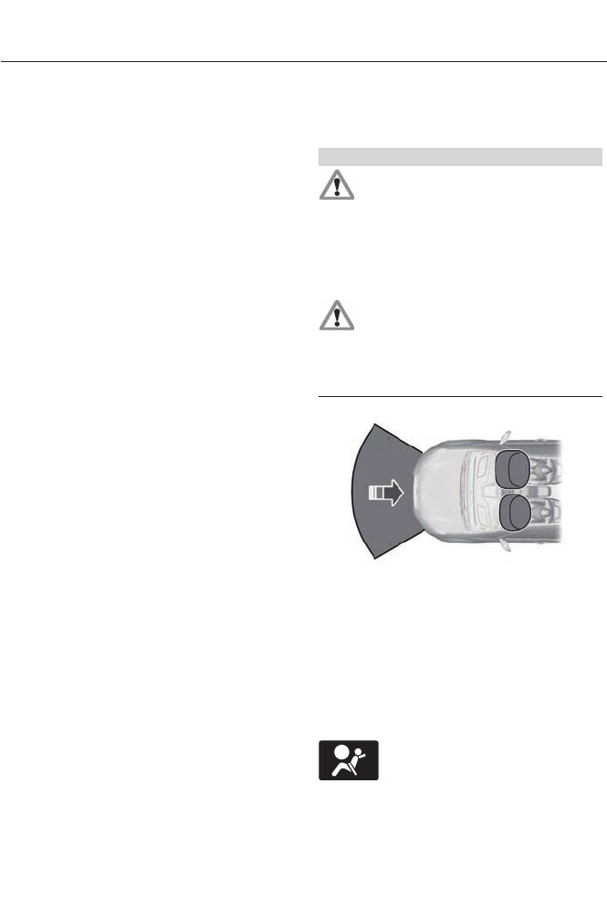
DRIVER AND PASSENGER
AIRBAGS
WARNINGS
Never place your arm or any objects
over an airbag module. Placing your
arm over a deploying airbag can
result in serious arm fractures or other
injuries. Objects placed on or over the
airbag inflation area may cause those
objects to be propelled by the airbag into
your face and torso causing serious injury.
Airbags can kill or injure a child in a
child seat. Never place a rear-facing
child seat in front of an active airbag.
If you must use a forward-facing child seat
in the front seat, move the seat all the way
back.
E151127
The driver and front passenger airbags will
deploy during significant frontal and near
frontal crashes.
The driver and passenger front airbag
system consists of:
• driver and passenger airbag modules.
• front passenger sensing system.
· crash sensors and monitoring
system with readiness indicator.
See Crash Sensors and Airbag
Indicator (page 40).
34
Supplementary Restraints System
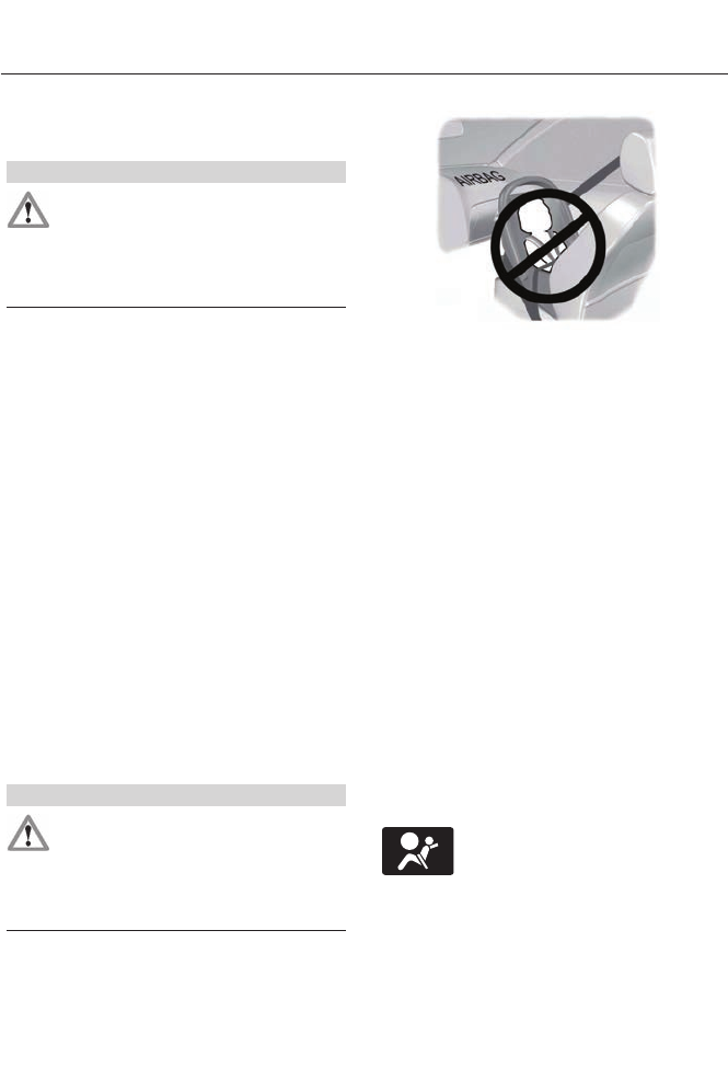
Proper Driver and Front Passenger
Seating Adjustment
WARNING
National Highway Traffic Safety
Administration (NHTSA)
recommends a minimum distance
of at least 10 inches (25 centimeters)
between an occupant’s chest and the
driver airbag module.
To properly position yourself away from
the airbag:
• Move your seat to the rear as far as you
can while still reaching the pedals
comfortably.
• Recline the seat slightly (one or two
degrees) from the upright position.
After all occupants have adjusted their
seats and put on safety belts, it is very
important that they continue to sit
properly. A properly seated occupant sits
upright, leaning against the seat back, and
centered on the seat cushion, with their
feet comfortably extended on the floor.
Sitting improperly can increase the chance
of injury in a crash event. For example, if
an occupant slouches, lies down, turns
sideways, sits forward, leans forward or
sideways, or puts one or both feet up, the
chance of injury during a crash is greatly
increased.
Children and Airbags
WARNING
Airbags can kill or injure a child in a
child seat. Never place a rear-facing
child seat in front of an active airbag.
If you must use a forward-facing child seat
in the front seat, move the seat all the way
back.
E142846
Children must always be properly
restrained. Accident statistics suggest that
children are safer when properly restrained
in the rear seating positions than in the
front seating position. Failure to follow
these instructions may increase the risk of
injury in a crash.
KNEE AIRBAG
A driver’s and passenger’s knee airbag is
located under or within the instrument
panel. During a crash, the restraints control
module may activate the driver’s and
passenger’s knee airbag (individually or
both) based on crash severity and
respective occupant conditions. Under
certain crash and occupant conditions, the
driver’s and passenger’s knee airbag may
deploy (individually or both) but the
corresponding front airbag may not
activate. As with front and side airbags, it
is important to be properly seated and
restrained to reduce the risk of death or
serious injury.
Make sure the knee airbags are
operating properly. See Crash
Sensors and Airbag Indicator
(page 40).
35
Supplementary Restraints System
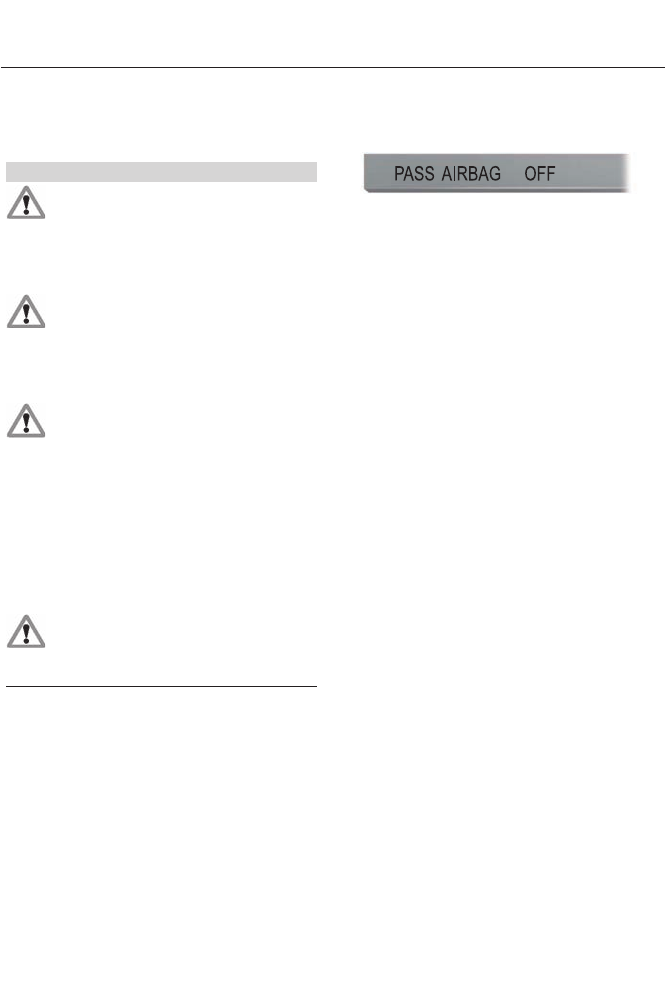
FRONT PASSENGER SENSING
SYSTEM
WARNINGS
Even with Advanced Restraints
Systems, children 12 and under
should be properly restrained in a
rear seating position. Failure to follow this
could seriously increase the risk of injury or
death.
Sitting improperly out of position or
with the seat back reclined too far
can take off weight from the seat
cushion and affect the decision of the front
passenger sensing system, resulting in
serious injury or death in a crash.
To reduce the risk of possible serious
injury: Do not stow objects in seat
back map pocket or hang objects off
seat back if a child is in the front passenger
seat. Do not place objects underneath the
front passenger seat or between the seat
and the center console. Check the
passenger airbag off or pass airbag off
indicator lamp for proper airbag status.
Failure to follow these instructions may
interfere with the front passenger seat
sensing system.
Any alteration or modification to the
front passenger seat may affect the
performance of the front passenger
sensing system.
This system works with sensors that are
part of the front passenger’s seat and
safety belt to detect the presence of a
properly-seated occupant and determine
if the front passenger’s frontal airbag
should be enabled (may inflate) or not.
E157152
The front passenger sensing system uses
a pass airbag off indicator which will
illuminate and stay lit to remind you that
the front passenger frontal airbag is
disabled. The indicator lamp is located at
the top center of the instrument panel.
Note: When the ignition is first tuned on,
the indicator lamp will illuminate for a short
period of time to confirm it is functional.
The front passenger sensing system is
designed to disable (will not inflate) the
front passenger's frontal airbag when a
rear facing infant seat, a forward-facing
child restraint, or a booster seat is
detected. Even with this technology,
parents are STRONGLY encouraged to
always properly restrain children in the rear
seat. The sensor also turns off the
passenger front airbag and seat-mounted
side airbag when the passenger seat is
empty.
• When the front passenger sensing
system disables (will not inflate) the
front passenger frontal airbag, the
indicator lamp will illuminate and stay
lit to remind you that the front
passenger frontal airbag is disabled.
• If the child restraint has been installed
and the indicator lamp is not lit, then
turn the vehicle off, remove the child
restraint from the vehicle and reinstall
the restraint following the child
restraint manufacturer's instructions.
36
Supplementary Restraints System

The front passenger sensing system is
designed to enable (may inflate) the front
passenger's frontal airbag anytime the
system senses that a person of adult size
is sitting properly in the front passenger
seat.
• When the front passenger sensing
system enables the front passenger
frontal airbag (may inflate), the
indicator lamp will be unlit and stay
unlit.
If a person of adult size is sitting in the front
passenger’s seat, but the airbag off
indicator lamp is lit, it is possible that the
person isn’t sitting properly in the seat. If
this happens:
• Turn the vehicle off and ask the person
to place the seat back in the full upright
position.
• Have the person sit upright in the seat,
centered on the seat cushion, with the
person’s legs comfortably extended.
• Restart the vehicle and have the person
remain in this position for about two
minutes. This will allow the system to
detect that person and enable the
passenger’s frontal airbag.
• If the indicator lamp remains lit even
after this, the person should be advised
to ride in the rear seat.
Passenger airbagPassenger airbag OFF indic-
ator
Occupant
DisabledUnlitEmpty
DisabledLitChild
EnabledUnlitAdult
Note: When the passenger airbag off light
is illuminated, the passenger (seat
mounted) side airbag may be disabled to
avoid the risk of airbag deployment injuries.
After all occupants have adjusted their
seats and put on safety belts, it is very
important that they continue to sit
properly. A properly seated occupant sits
upright, leaning against the seat back, and
centered on the seat cushion, with their
feet comfortably extended on the floor.
Sitting improperly can increase the chance
of injury in a crash event. For example, if
an occupant slouches, lies down, turns
sideways, sits forward, leans forward or
sideways, or puts one or both feet up, the
chance of injury during a crash is greatly
increased.
If you think that the status of the passenger
airbag off indicator lamp is incorrect, check
for the following:
• Objects lodged underneath the seat
• Objects between the seat cushion and
the center console
• Objects hanging off the seat back
• Objects stowed in the seat back map
pocket
• Objects placed on the occupant's lap
37
Supplementary Restraints System
• Cargo interference with the seat
• Other passengers pushing or pulling on
the seat
• Rear passenger feet and knees resting
or pushing on the seat
The conditions listed above may cause the
weight of a properly seated occupant to
be incorrectly interpreted by the front
passenger sensing system. The person in
the front passenger seat may appear
heavier or lighter due to the conditions
described in the list above.
Make sure the front passenger
sensing system is operating
properly. See Crash Sensors
and Airbag Indicator (page 40).
If the airbag readiness light is lit, do the
following:
The driver and adult passengers should
check for objects lodged underneath the
front passenger seat, or cargo interfering
with the seat.
If there are lodged objects, or cargo is
interfering with the seat, take the following
steps to remove the obstruction:
• Pull the vehicle over.
• Turn the vehicle off.
• Driver and adult passengers should
check for any objects lodged
underneath the front passenger seat
or cargo interfering with the seat.
• Remove the obstruction(s) (if found).
• Restart the vehicle.
• Wait at least two minutes and verify
that the airbag readiness light is no
longer illuminated.
• If the airbag readiness light remains
illuminated, this may or may not be a
problem due to the front passenger
sensing system.
Do not attempt to repair or service the
system. Take your vehicle immediately to
an authorized dealer.
If it is necessary to modify an advanced
front airbag system to accommodate a
person with disabilities, contact the Ford
Customer Relationship Center. See
Getting the Services You Need (page
212).
SIDE AIRBAGS
WARNINGS
Do not place objects or mount
equipment on or near the airbag
cover, on the side of the seat backs
(of the front seats), or in front seat areas
that may come into contact with a
deploying airbag. Failure to follow these
instructions may increase the risk of
personal injury in the event of a crash.
Do not use accessory seat covers.
The use of accessory seat covers
may prevent the deployment of the
side airbags and increase the risk of injury
in an accident.
Do not lean your head on the door.
The side airbag could injure you as it
deploys from the side of the seat
back.
Do not attempt to service, repair, or
modify the airbag, its fuses or the
seat cover on a seat containing an
airbag as you could be seriously injured or
killed. Contact your authorized dealer as
soon as possible.
If the side airbag has deployed, the
airbag will not function again. The
side airbag system (including the
seat) must be inspected and serviced by
an authorized dealer. If the airbag is not
replaced, the unrepaired area will increase
the risk of injury in a crash.
38
Supplementary Restraints System
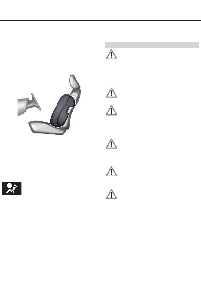
The side airbags are located on the
outboard side of the seat backs of the front
seats. In certain lateral crashes, the airbag
on the side affected by the crash will be
inflated. The airbag was designed to inflate
between the door panel and occupant to
further enhance the protection provided
occupants in side impact crashes.
E152533
The system consists of the following:
• A label or embossed side panel
indicating that side airbags are fitted
to your vehicle
• Side airbags located inside the driver
and front passenger seat backs
• Front passenger sensing system
·Crash sensors and monitoring
system with readiness indicator.
See Crash Sensors and Airbag
Indicator (page 40).
Note: The passenger sensing system will
deactivate the passenger seat-mounted
side airbag if it detects an empty passenger
seat.
The design and development of the side
airbag system included recommended
testing procedures that were developed
by a group of automotive safety experts
known as the Side Airbag Technical
Working Group. These recommended
testing procedures help reduce the risk of
injuries related to the deployment of side
airbags.
SIDE CURTAIN AIRBAGS
WARNINGS
Do not place objects or mount
equipment on or near the headliner
at the siderail that may come into
contact with a deploying side curtain
airbag. Failure to follow these instructions
may increase the risk of personal injury in
the event of a crash.
Do not lean your head on the door.
The side curtain airbag could injure
you as it deploys from the headliner.
Do not attempt to service, repair, or
modify the side curtain airbags, its
fuses, the A, B, or C pillar trim, or the
headliner on a vehicle containing side
curtain airbags. Contact your authorized
dealer as soon as possible.
All occupants of the vehicle including
the driver should always wear their
safety belts even when an airbag
supplemental restraint system and side
curtain airbag is provided.
To reduce risk of injury, do not
obstruct or place objects in the
deployment path of the side curtain
airbag.
If the side curtain airbags have
deployed, the side curtain airbags
will not function again. The side
curtain airbags (including the A, B and C
pillar trim and headliner) must be
inspected and serviced by an authorized
dealer. If the side curtain airbag is not
replaced, the unrepaired area will increase
the risk of injury in a crash.
39
Supplementary Restraints System
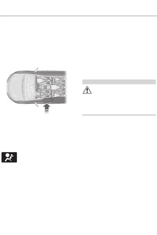
The side curtain airbags will deploy during
significant side crashes. The side curtain
airbags are mounted to the roof side-rail
sheet metal, behind the headliner, above
each row of seats. The side curtain airbags
are designed to inflate between the side
window area and occupants to further
enhance protection provided in side impact
crashes.
The system consists of the following:
E75004
• Side curtain airbags located above the
trim panels over the front and rear side
windows identified by a label or
wording on the headliner or roof-pillar
trim.
• A flexible headliner which opens above
the side doors to allow side air curtain
deployment.
Crash sensors and monitoring
system with readiness indicator.
See Crash Sensors and Airbag
Indicator (page 40).
Children 12 years old and under should
always be properly restrained in the back
seats. The side curtain airbags will not
interfere with children restrained using a
properly installed child or booster seat
because it is designed to inflate downward
from the headliner above the doors along
the side window opening.
The design and development of the side
curtain airbags included recommended
testing procedures that were developed
by a group of automotive safety experts
known as the Side Airbag Technical
Working Group. These recommended
testing procedures help reduce the risk of
injuries related to the deployment of side
curtain airbags.
CRASH SENSORS AND
AIRBAG INDICATOR
WARNING
Modifying or adding equipment to
the front end of the vehicle (including
frame, bumper, front end body
structure and tow hooks) may affect the
performance of the airbag system,
increasing the risk of injury. Do not modify
the front end of the vehicle.
The vehicle has a collection of crash and
occupant sensors which provide
information to the restraints control
module which deploys (activates) the
front safety belt pretensioners, driver
airbag, passenger airbag, knee airbag(s),
seat mounted side airbags, and the side
curtain airbags. Based on the type of crash
(frontal impact or side impact), the
restraints control module will deploy the
appropriate safety devices.
The restraints control module also
monitors the readiness of the above safety
devices plus the crash and occupant
sensors. The readiness of the safety
system is indicated by a warning indicator
light in the instrument cluster or by a
backup tone if the warning light is not
working. Routine maintenance of the
airbag is not required.
A difficulty with the system is indicated by
one or more of the following:
40
Supplementary Restraints System

The readiness light will not
illuminate immediately after the
ignition is turned on.
• The readiness light will either flash or
stay lit.
• A series of five beeps will be heard. The
tone pattern will repeat periodically
until the problem, the light or both are
repaired.
If any of these things happen, even
intermittently, have the supplemental
restraint system serviced at an authorized
dealer immediately. Unless serviced, the
system may not function properly in the
event of a crash.
The safety belt pretensioners and the front
airbag supplemental restraint system are
designed to activate when the vehicle
sustains longitudinal deceleration
sufficient to cause the restraints control
module to deploy a safety device.
The fact that the safety belt pretensioners
or front airbags did not activate for both
front seat occupants in a crash does not
mean that something is wrong with the
system. Rather, it means the restraints
control module determined the accident
conditions (crash severity, belt usage)
were not appropriate to activate these
safety devices.
• The design of the front airbags is to
activate only in frontal and near-frontal
crashes (not rollovers, side impacts or
rear impacts) unless the crash causes
sufficient longitudinal deceleration.
• The design of the safety belt
pretensioners is to activate in frontal
and near-frontal crashes, and may also
activate when a side curtain deploys.
• The knee airbag may deploy based on
crash severity and occupant conditions.
• The design of the side airbags and side
curtain airbags is to inflate in certain
side impact crashes. Side airbags and
side curtain airbags may activate in
other types of crashes if the vehicle
experiences sufficient sideways motion
or deformation.
AIRBAG DISPOSAL
Contact your authorized dealer as soon as
possible. Airbags must be disposed of by
qualified personnel.
41
Supplementary Restraints System
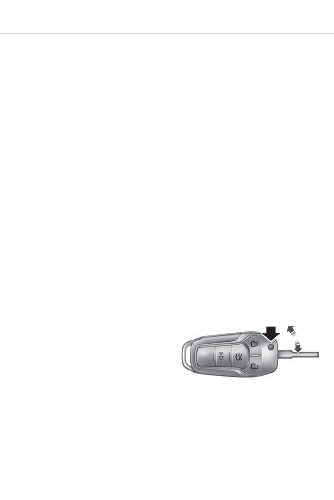
GENERAL INFORMATION ON
RADIO FREQUENCIES
This device complies with Part 15 of the
FCC Rules and with Industry Canada
license-exempt RSS standard(s).
Operation is subject to the following two
conditions: (1) This device may not cause
harmful interference, and (2) This device
must accept any interference received,
including interference that may cause
undesired operation.
Note: Changes or modifications not
expressively approved by the party
responsible for compliance could void the
user's authority to operate the equipment.
The term IC before the radio certification
number only signifies that Industry Canada
technical specifications were met.
The typical operating range for your
transmitter is approximately 33 feet (10
meters). Vehicles with the remote start
feature will have a greater range. One of
the following could cause a decrease in
operating range:
• weather conditions
• nearby radio towers
• structures around the vehicle
• other vehicles parked next to your
vehicle
The radio frequency used by your remote
control can also be used by other short
distance radio transmissions, for example
amateur radios, medical equipment,
wireless headphones, remote controls and
alarm systems. If the frequencies are
jammed, you will not be able to use your
remote control. You can lock and unlock
the doors with the key.
Note: Make sure to lock your vehicle before
leaving it unattended.
Note: If you are in range, the remote control
will operate if you press any button
unintentionally.
Intelligent Access (If Equipped)
The system uses a radio frequency signal
to communicate with your vehicle and
authorize your vehicle to unlock when one
of the following conditions are met:
• You touch the inside of the front
exterior door handle.
• You press the luggage compartment
button.
• You press a button on the transmitter.
If excessive radio frequency interference
is present in the area or if the transmitter
battery is low, you may need to
mechanically unlock your door. You can
use the mechanical key blade in your
intelligent access key to open the driver
door in this situation. See Remote
Control (page 42).
REMOTE CONTROL
Integrated Keyhead Transmitters
(If Equipped)
Use the key blade is used to start the
vehicle and unlock or lock the driver’s door
from outside the vehicle. The transmitter
portion functions as the remote control.
E151797
Press the button to release the key. Press
and hold the button to fold the key back
in when not in use.
42
Keys and Remote Controls
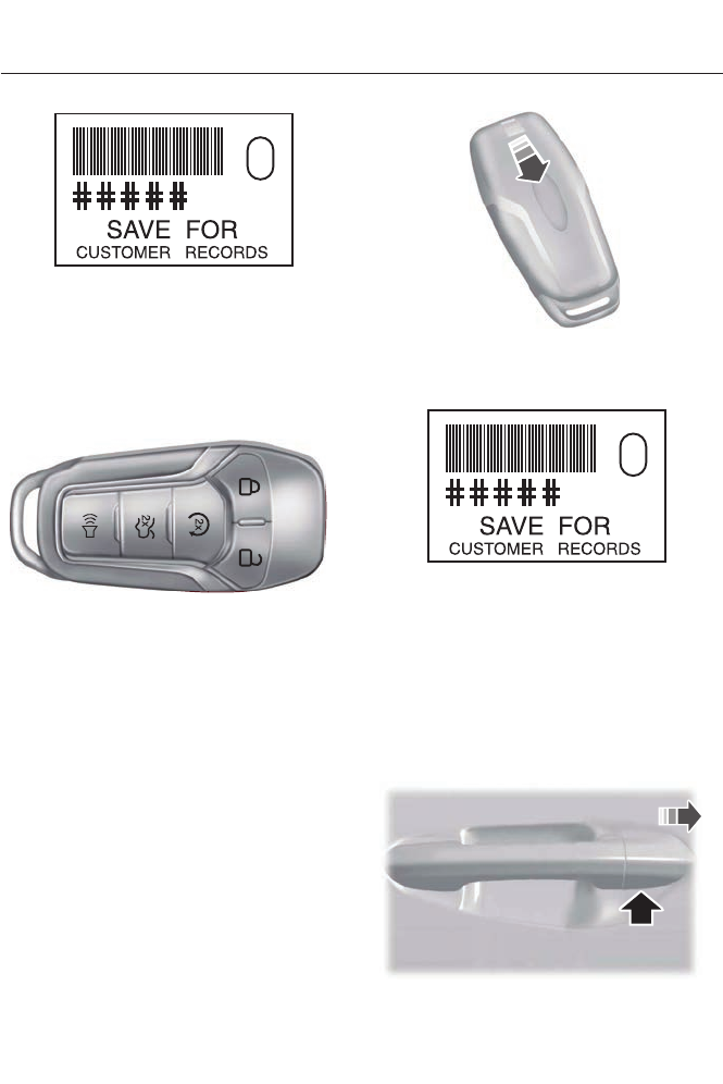
E151795
Note: Your vehicle’s keys came with a
security tag that provides important vehicle
key cut information. Keep the tag in a safe
place for future reference.
Intelligent Access Key (If Equipped)
E144506
Your intelligent access keys operate the
power locks and the remote start system.
The key must be in your vehicle to activate
the push-button start system.
Removable Key Blade
The intelligent access key also contains a
removable mechanical key blade that you
can use to unlock the driver door.
E151796
Slide the release on the back of the remote
control and pivot the cover off to access
the key blade.
E151795
Note: Your vehicle’s backup keys came with
a security tag that provides important
vehicle key cut information. Keep the tag in
a safe place for future reference.
Using the Key Blade
The key cylinder is hidden under a cap on
the driver door handle.
To remove the cap:
E151956
43
Keys and Remote Controls
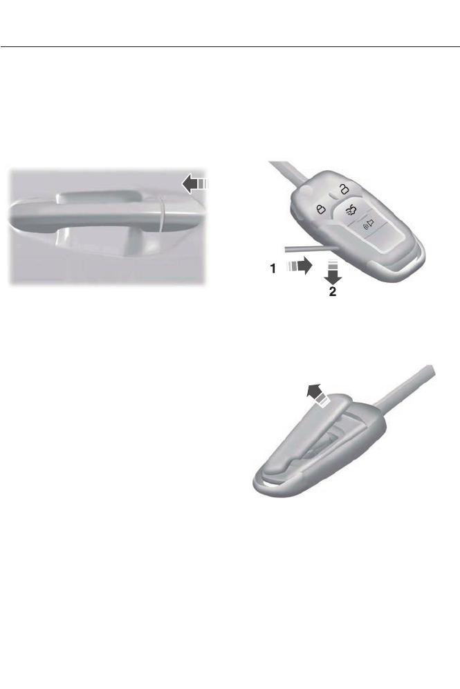
1. Insert the key blade into the slot on the
bottom of the handle and press up.
2. While maintaining upward pressure,
move the cap rearward to release it.
Gently remove the key while doing so.
To install the cap:
E151957
1. Place the cap just forward of the key
cylinder.
2. While applying pressure to the cap,
move it forward until it is in place. You
may hear a snap as it engages.
Make sure the cap is properly installed by
trying to move it rearward.
Replacing the Battery
Note: Refer to local regulations when
disposing of transmitter batteries.
Note: Do not wipe off any grease on the
battery terminals or on the back surface of
the circuit board.
Note: Replacing the battery will not delete
the transmitter from the vehicle. The
transmitter should operate normally.
A message will appear in the information
display when the remote control battery
is low. See Information Messages (page
96).
Integrated Keyhead Transmitter
The remote control uses one coin-type
three-volt lithium battery CR2032 or
equivalent.
Press the button to release the key before
beginning the procedure.
E151798
1. Insert a screwdriver in the position
shown and gently push the clip.
2. Press the clip down to release the
battery cover.
E151799
3. Carefully remove the cover.
44
Keys and Remote Controls
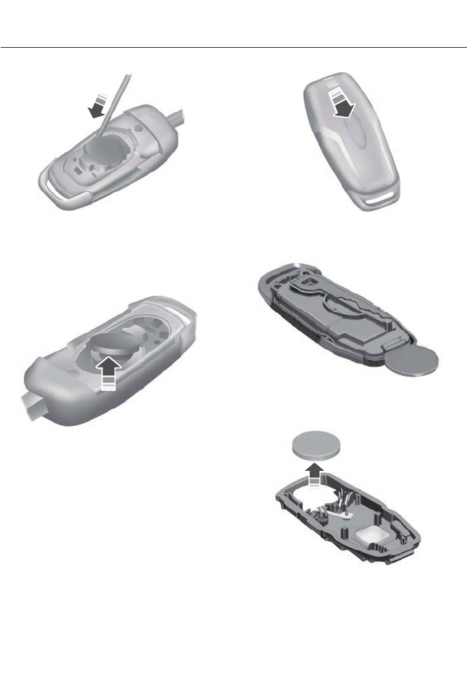
Note: Do not touch the battery contacts or
the printed circuit board with the
screwdriver.
4. Insert a screwdriver as shown to
release the battery.
E151801
5. Remove the battery.
6. Install a new battery with the + facing
up.
7. Replace the battery cover.
Intelligent Access Transmitter
The remote control uses two coin-type
three-volt lithium batteries CR2025 or
equivalent.
E151796
1. Slide the release on the back of the
remote control and pivot the cover off.
E153890
2. Insert a coin into the slot and twist to
separate the housing.
E153891
3. Remove the batteries.
4. Install new batteries with the + facing
each other.
Note: Make sure to replace the label
between the two batteries.
45
Keys and Remote Controls
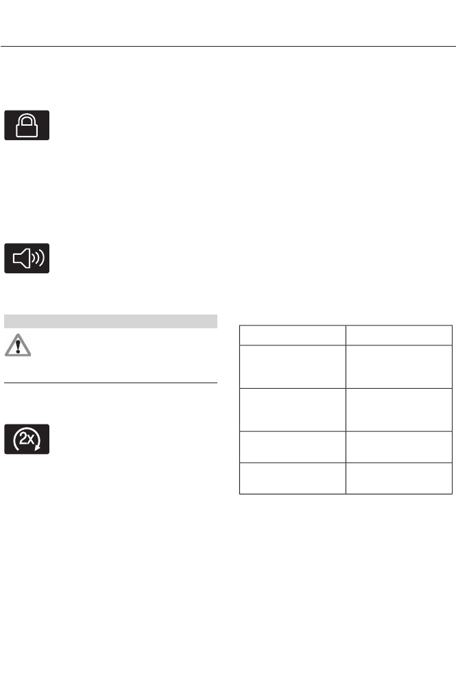
5. Reinstall the housing and cover.
Car Finder
E138623
Press the button twice within
three seconds. The horn will
sound and the turn signals will
flash. It is recommended that this method
be used to locate your vehicle, rather than
using the panic alarm.
Sounding a Panic Alarm
Note: The panic alarm will only operate
when the ignition is off.
E138624
Press the button to activate the
alarm. Press the button again or
turn the ignition on to deactivate.
Remote Start (If Equipped)
WARNING
To avoid exhaust fumes, do not use
remote start if your vehicle is parked
indoors or areas that are not well
ventilated.
Note: Do not use remote start if your vehicle
is low on fuel.
E138625
The remote start button is on the
transmitter.
This feature allows you to start your
vehicle from outside the vehicle. The
transmitter has an extended operating
range.
Vehicles with automatic climate control
can be configured to operate when the
vehicle is remote started. See Climate
Control (page 109). A manual climate
control system will run at the setting it was
set to when the vehicle was last turned off.
Many states and provinces have
restrictions for the use of remote start.
Check your local and state or provincial
laws for specific requirements regarding
remote start systems.
The remote start system will not work if:
• the ignition is on
• the alarm system triggered
• you disable the feature
• the hood is open
• the transmission is not in P
• the vehicle battery voltage is too low
• the service engine soon light is on.
Remote Control Feedback
An LED on the remote control provides
status feedback of remote start or stop
commands.
StatusLED
Remote start or
extension
successful
Solid green
Remote stop
successful; engine
off
Solid red
Remote start or
stop failed
Blinking red
Waiting for status
update
Blinking green
Remote Starting the Vehicle
Note: Each button press must be done
within three seconds of each other. The
vehicle will not remote start if this sequence
is not followed and the horn will not sound.
46
Keys and Remote Controls
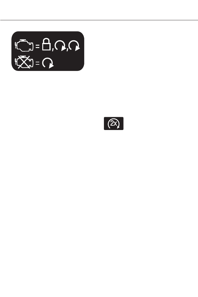
E138626
The tag with your transmitter details the
starting procedure.
To remote start your vehicle:
1. Press the lock button to lock all the
doors.
2. Press the remote start button twice.
The exterior lamps will flash twice.
The horn will sound if the system fails to
start, unless quiet start is on. Quiet start
will run the blower fan at a slower speed
to reduce noise. It can be switched on or
off in the information display. See General
Information (page 84).
Note: If the vehicle has been remote started
and is equipped with an integrated keyhead
transmitter, you must turn the ignition on
before driving the vehicle. If equipped with
an intelligent access transmitter, you must
press the START/STOP button on the
instrument panel once while applying the
brake pedal before driving your vehicle.
The power windows will be inhibited during
the remote start and the radio will not turn
on automatically.
The parking lamps will remain on and the
engine will run for 5, 10, or 15 minutes,
depending on the setting.
Extending the Vehicle Run Time
Repeat Steps 1 and 2 with the vehicle still
running to extend the run time for another
remote start duration. If you programmed
the duration to last 10 minutes, the second
10 minutes will begin after what is left of
the first activation time. For example, if the
vehicle had been running from the first
remote start for five minutes, the vehicle
will continue to run now for a total of 15
minutes.
Wait at least five seconds before remote
starting after a vehicle shutdown.
Turning the Vehicle Off After Remote
Starting
E138625
Press the button once. The
parking lamps will turn off.
You may have to be closer to the
vehicle than when starting due to ground
reflection and the added noise of the
running vehicle.
You can disable or enable the remote start
system through the information display.
See General Information (page 84).
REPLACING A LOST KEY OR
REMOTE CONTROL
Replacement keys or remote controls can
be purchased from an authorized dealer.
Authorized dealers can program remote
controls for your vehicle. See Passive
Anti-Theft System (page 59).
To re-program the passive anti-theft
system see an authorized dealer.
47
Keys and Remote Controls

PRINCIPLE OF OPERATION
MyKey allows you to program keys with
restricted driving modes to promote good
driving habits. Program all but one of the
keys to activate the restricted modes.
Any keys that remain unprogrammed are
referred to as administrator keys or admin
keys. They can be used to:
• create a MyKey
• program optional MyKey settings
• clear all MyKey features.
Once you program a MyKey, you can
access the following information through
the information display to learn:
• The number of admin keys and MyKeys
programmed to your vehicle.
• The total distance your vehicle traveled
with a MyKey.
Note: Switch the ignition on to use the
system.
Note: All MyKeys are programmed to the
same settings. You cannot program them
individually.
Note: In vehicles equipped with the
intelligent access key (push-button start):
When both a MyKey and an admin fob are
present, your vehicle will recognize the
admin fob to start the engine.
Standard Settings
The following settings cannot be changed:
• Belt-Minder. You cannot disable this
feature. With a MyKey, the five-minute
timer does not expire and the audio
system mutes.
• Early low fuel. The low-fuel warning
activates earlier, giving MyKey users
more time to refuel.
• Driver assist features, if equipped, are
forced on: Rear parking aid, blind spot
information system (BLIS) with cross
traffic alert, lane keeping system and
collision warning system.
• Satellite radio adult content
restrictions activate.
Optional Settings
You can configure MyKey settings while
programming a MyKey or change them
while using an admin key.
• Vehicle speed limit: You can set various
vehicle speed limits of 65, 70, 75 and
80 mph (105, 113, 121 and 130 km/h) so
that drivers receive visual warnings and
an audible tone when they reach the
selected top speed.
• Vehicle speed minders: You can set
various vehicle speed minders of 45,
55 or 65 mph (75, 90, or 105 km/h) so
that drivers receive visual warnings and
an audible tone when they exceed the
preselected vehicle speed limit.
• Audio system maximum volume limit:
You can limit the audio system's
maximum output to 45% and disable
the speed-sensitive compensated
volume feature. The audio system
displays a message when drivers
attempt to exceed the volume limit.
• Always on setting: Certain driving aids
cannot be disabled or turned off when
drivers use a MyKey, such as
AdvanceTrac, 911 Assist or the Do not
disturb feature (if your vehicle is
equipped with these features).
Vehicles with Keyless Entry
If a MyKey and an admin key are present
within the vehicle at the same time, your
vehicle will recognize the admin key only.
48
MyKey™
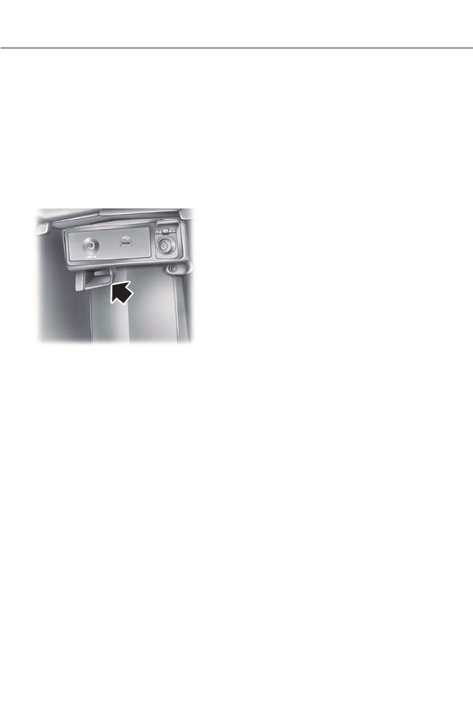
CREATING A MYKEY
Use the information display to create a
MyKey:
1. Insert the key you want to program into
the ignition. If your vehicle is equipped with
a push-button start, put the intelligent
access key in the backup slot. See
Starting and Stopping the Engine (page
132).
E147165
2. Switch the ignition on.
3. From the main menu within the
information display, press OK or the >
button to navigate through the various
screens. Select Settings, then MyKey.
4. Press OK to select Create.
5. When prompted, hold the OK button
until you see a message informing you to
label this key as a MyKey. The key will be
restricted at the next start.
MyKey is successfully created. Make sure
you label it so you can distinguish it from
the admin keys.
Programming/Changing Optional
Settings
Note: You can clear or change your MyKey
settings at any time during the same key
cycle as you created them with either the
MyKey or an admin key. Once you have
switched the engine off, however, you will
need an admin key to change or clear your
MyKey settings.
Using the information display, access your
optional MyKey settings.
1. Switch the ignition on using an admin
key or fob.
2. Access the main menu and select
Settings, then MyKey.
3. Use the arrow buttons to get to an
optional feature.
4. Press OK or > to scroll through
settings.
5. Press OK or > to make a selection.
CLEARING ALL MYKEYS
You can clear all MyKeys within the same
key cycle as you created the MyKey. If you
switch your ignition off, however, you will
need to use an admin key to clear your
MyKeys.
Note: When you clear your MyKeys, you
remove all restrictions and return all MyKeys
to their original admin key status at once.
To clear all MyKeys of all MyKey settings,
use the information display to do the
following:
1. Access the main menu and select
Settings, then MyKey.
2. Scroll to Clear All and press the OK
button.
3. Hold the OK button until ALL
MYKEYS CLEARED displays.
49
MyKey™

CHECKING MYKEY SYSTEM
STATUS
The information display shows the
programmed keys' status:
•MYKEY DISTANCE: Tracks distance
when drivers use restricted keys. The
only way to delete the accumulated
distance is by using an admin key to
reset this to zero. If the MyKey distance
does not accumulate as expected,
then:
• The intended user is not using the
programmed key.
• An admin key user recently reset
the distance.
•NUMBER OF MYKEY(S): Indicates
the number of restricted keys
programmed to the vehicle. Use this
feature to detect how many restricted
keys you have for your vehicle, or when
a MyKey has recently been deleted.
•NUMBER OF ADMIN KEY(S):
Indicates how many admin keys are
programmed to the vehicle. Use this
feature to determine how many
unrestricted keys you have for your
vehicle, or if an additional MyKey has
been programmed.
USING MYKEY WITH REMOTE
START SYSTEMS
MyKey is not compatible with non
Ford-approved, aftermarket remote start
systems. If you choose to install a remote
start system, see an authorized dealer for
a Ford-approved remote start system.
MYKEY TROUBLESHOOTING
Potential CausesCondition
· The key in the ignition does not have admin
privileges.
I cannot program a key.
· The key in the ignition is the only admin
key (there always has to be at least one
admin key).
· The intelligent access key is not in the
backup slot (vehicles with push-button
start).
· SecuriLock passive anti-theft system is
disabled or in unlimited mode.
· The key in the ignition does not have admin
privileges.
I cannot program the optional settings.
· No keys are programmed to the vehicle.
See Creating a MyKey (page 49).
· The key in the ignition does not have admin
privileges.
I cannot clear the restricted keys.
50
MyKey™

Potential CausesCondition
· No restricted keys are programmed to the
vehicle. See Creating a MyKey (page 49).
· Purchase a new key from your authorized
dealer.
I lost the only admin key.
· Program a spare key. See Passive Anti-
Theft System (page 59).
I lost a key.
· An admin fob is present at engine start-
up.
No restricted key functions with intelligent
access key (push-button start).
· No MyKey keys are programmed to the
vehicle. See Creating a MyKey (page 49).
· The intended user is not using the
programmed MyKey.
MyKey miles do not accumulate.
· An admin key holder reset the key system.
51
MyKey™
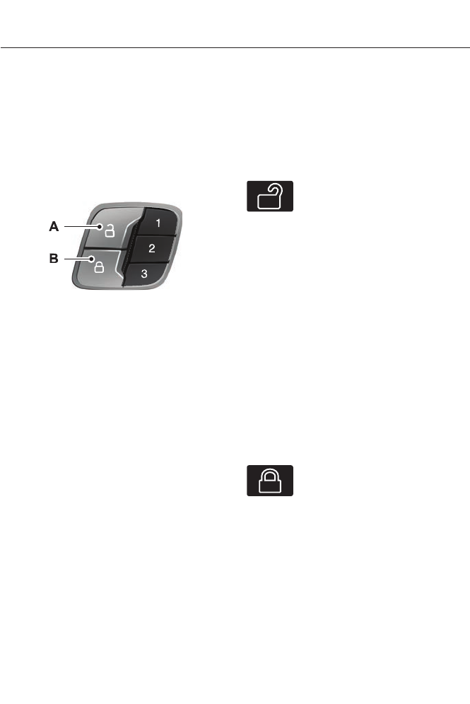
LOCKING AND UNLOCKING
You can use the power door lock control
or the remote control to lock and unlock
the vehicle.
Power Door Locks
The power door lock control is on the driver
and front passenger door panels.
E138628
UnlockA
LockB
Door Lock Indicator
An LED on each door window trim will light
when you lock the door. It will remain lit for
up to 10 minutes after you switch off the
ignition.
Switch Inhibitor
When you electronically lock your vehicle,
the power door lock switch will no longer
operate after 20 seconds. You must unlock
your vehicle with the remote control or
keyless keypad, or switch the ignition on,
to restore function to these switches. You
can switch this feature on or off in the
information display. See General
Information (page 84).
Rear Door Unlocking and Opening
Pull the interior door release handle twice
to unlock and open the rear door. The first
pull unlocks the door and the second pull
will unlatch the door.
Remote Control
You can use the remote control at any
time. The luggage compartment release
button will only work when the vehicle
speed is less than 5 mph (8 km/h).
Unlocking the Doors (Two-Stage
Unlock)
E138629
Press the button to unlock the
driver door.
Press the button again within
three seconds to unlock all doors. The turn
signals will flash.
Press and hold both the lock and unlock
buttons on the remote control for three
seconds to change between driver door or
all doors unlock mode. The turn signals will
flash twice to indicate a change to the
unlocking mode. Driver door unlock mode
will only unlock the driver door when the
unlock button is pressed once. All door
unlock mode will unlock all doors with one
press of the unlock button. The unlocking
mode applies to the remote control,
keyless entry keypad and intelligent
access. You can also change the mode in
the information display. See General
Information (page 84).
Locking the Doors
E138623
Press the button to lock all the
doors. The turn signals will
illuminate.
Press the button again within three
seconds to confirm that all the doors are
closed. The doors will lock again, the horn
will sound and the turn signals will
illuminate if all the doors and the luggage
compartment are closed.
52
Locks
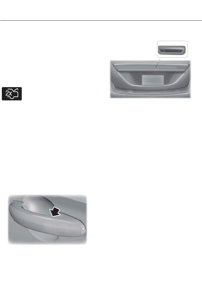
Mislock
If any door or the luggage compartment is
open, or if the hood is open on vehicles
with an anti-theft alarm or remote start,
the horn will sound twice and the lamps
will not flash. You can enable or disable
this feature in the information display. See
General Information (page 84).
Opening the Luggage Compartment
E138630
Press twice within three seconds
to open the luggage
compartment.
Make sure to close and latch the luggage
compartment before driving your vehicle.
An unlatched luggage compartment may
cause objects to fall out or block your view.
Activating Intelligent Access (If
Equipped)
You must have the intelligent access key
within 3 feet (1 meter) of your vehicle.
At a Door
Pull an exterior door handle to unlock and
open the door. Make sure not to touch the
lock sensor on top of the handle.
E157085
Touch the top of the door handle to lock
your vehicle.
At the Luggage Compartment
E144402
Press the exterior release button hidden
above the license plate.
Smart Unlocks For Integrated
Keyhead Transmitter
This feature helps to prevent you from
locking yourself out of your vehicle if your
key is still in the ignition.
When you open one of the front doors and
lock the vehicle with the power door lock
control, all the doors will lock then unlock
and the horn will sound twice if your key is
still in the ignition.
You can still lock your vehicle with the key
in the ignition. To do this, use the keyless
entry keypad with the driver door closed,
or press the lock button on the transmitter
even if the doors are not closed.
If both front doors are closed, you can lock
your vehicle by any method, regardless of
whether the key is in the ignition or not.
Smart Unlocks For Intelligent
Access Keys (If Equipped)
This feature helps to prevent you from
unintentionally locking your intelligent
access key inside your vehicle’s passenger
compartment or rear cargo area.
53
Locks

When you electronically lock your vehicle
(with any door open, vehicle in park and
ignition off), the vehicle will search for an
intelligent access key in the passenger
compartment after you close the last door.
If your vehicle finds a key, all of the doors
will immediately unlock and the horn will
sound twice, indicating that a key is inside.
You can override the smart unlock feature
and intentionally lock the intelligent access
key inside your vehicle. To do this, lock your
vehicle after you have closed all the doors
by:
• using the keyless entry keypad
• pressing the lock button on another
intelligent access key
• touching the locking area on the handle
with another intelligent access key in
your hand.
When you open one of the front doors and
lock your vehicle using the power door lock
control, all doors will lock then unlock if:
• the ignition is on, or
• the ignition is off and your vehicle is not
in P.
Auto Relock
If you press the unlock button on the
remote control and do not open a door
within 45 seconds, your vehicle will lock
and the alarm will arm. You can enable or
disable this feature in the information
display. See General Information (page
84).
Autolock Feature
The autolock feature will lock all the doors
when:
• all doors are closed,
• the ignition is on,
• you shift into any gear putting your
vehicle in motion, and
• your vehicle attains a speed greater
than 12 mph (20 km/h).
The autolock feature repeats when:
• you open then close any door while the
ignition is on and your vehicle speed is
9 mph (15 km/h) or lower, and
• your vehicle then attains a speed
greater than 12 mph (20 km/h).
Autounlock Feature
The autounlock feature will unlock all the
doors when:
• the ignition is on, all the doors are
closed, and your vehicle has been in
motion at a speed greater than 12 mph
(20 km/h);
• your vehicle comes to a stop and you
switch the ignition off or to accessory;
and
• you open the driver door within 10
minutes of the switching the ignition
off or to accessory.
Note: The doors will not autounlock if you
electronically lock your vehicle after you
switch the ignition off and before you open
the driver door.
Enabling or Disabling
Note: You can enable or disable the
autolock and autounlock features
independently of each other.
You can enable or disable these features
in the information display or your
authorized dealer can do it for you. See
General Information (page 84).
Illuminated Entry
The interior lamps and select exterior
lamps will illuminate when you unlock the
doors with the remote entry system.
54
Locks
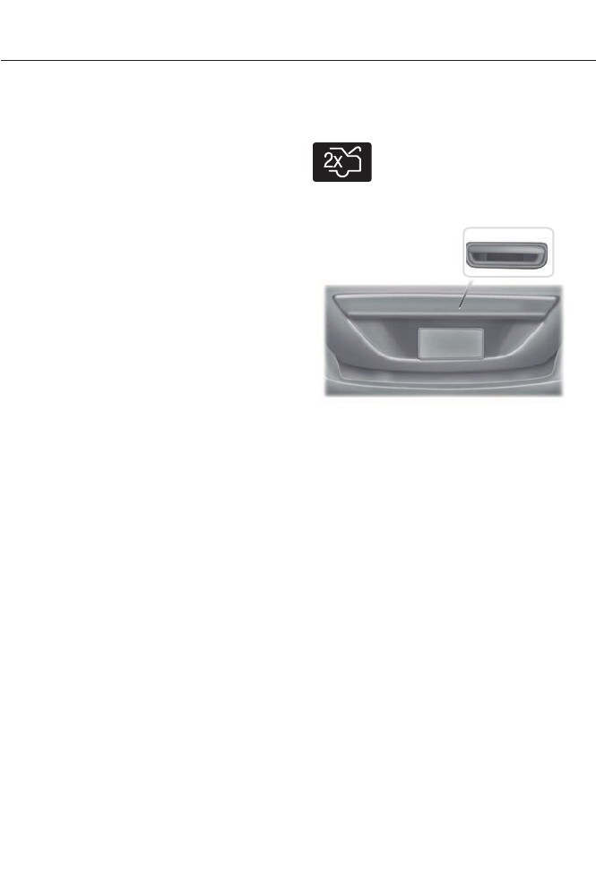
The illuminated entry system will turn off
the lights if:
• the ignition is on,
• you press the remote control lock
button, or
• after 25 seconds of illumination.
The lights will not turn off if:
• you turn them on with the lamp control,
or
• any door is open.
Illuminated Exit
The interior lamps and select exterior
lamps will illuminate when all doors are
closed, you switch the ignition off and you
remove the key from the ignition
(integrated keyhead transmitter only).
The lamps will turn off if all the doors
remain closed and:
• 25 seconds elapse
• you insert the key in the ignition
(integrated keyhead transmitter only)
• you press the START/STOP button
(intelligent access key only).
Battery Saver
If you leave the courtesy lamps, dome
lamps or headlamps on, the battery saver
will shut them off 10 minutes after you
switch the ignition off.
Accessory Mode Battery Saver for
Intelligent Access Keys (If Equipped)
If you leave your vehicle in the run ignition
state, it will shut off once it detects a
certain amount of battery drain or after 45
minutes.
Luggage Compartment
With the Remote Control
E138630
Press twice within three seconds
to unlatch the trunk.
From Outside Your Vehicle
E144402
Press the release button above the license
plate to unlatch the trunk. Your vehicle
must be unlocked or have an intelligent
access transmitter within 3 feet (1 meter)
of the trunk.
KEYLESS ENTRY (IF EQUIPPED)
SECURICODE™ KEYLESS ENTRY
KEYPAD
The keypad is located near the driver
window. It is invisible until touched and
then it lights up so you can see and touch
the appropriate buttons.
Note: If you enter your entry code too fast
on the keypad, the unlock function may not
work. Re-enter your entry code more slowly.
55
Locks

E138637
You can use the keypad to:
• lock or unlock the doors
• release the trunk
• recall memory seat and mirror
positions (if equipped)
• program and erase user codes
• arm and disarm the anti-theft alarm.
You can operate the keypad with the
factory-set 5-digit entry code. The code is
located on the owner’s wallet card in the
glove box and is available from an
authorized dealer. You can also create up
to five of your own 5-digit personal entry
codes.
Programming a Personal Entry Code
To create your own personal entry code:
1. Enter the factory-set code.
2. Press 1·2 on the keypad within five
seconds.
3. Enter your personal 5-digit code. You
must enter each number within five
seconds of each other.
4. Press 1·2 on the keypad to save
personal code 1.
The doors will lock then unlock to confirm
that programming was successful.
To program additional personal entry
codes, repeat Steps 1-3, then for Step 4:
• press 3·4 to save personal code 2
• press 5·6 to save personal code 3
• press 7·8 to save personal code 4
• press 9·0 to save personal code 5.
You may also program a personal entry
code through the MyFord Touch system
(if equipped). See Settings (page 358).
Tips:
• Do not set a code that uses five of the
same number.
• Do not use five numbers in sequential
order.
• The factory-set code will work even if
you have set your own personal code.
Recalling Memory Positions (If
Equipped)
The programmed entry codes will recall
driver memory positions as follows:
• Entry code 1 will recall driver 1 memory
positions.
• Entry code 2 will recall driver 2 memory
positions.
• Entry code 3 will recall driver 3 memory
positions.
Note: Personal entry codes 4 and 5 will not
recall memory positions.
Erasing a Personal Code
1. Enter the factory-set 5-digit code.
2. Press and release 1·2 on the keypad
within five seconds.
3. Press and hold 1·2 for two seconds.
You must do this within five seconds
of completing Step 2.
All personal codes are now erased and only
the factory-set 5–digit code will work.
56
Locks
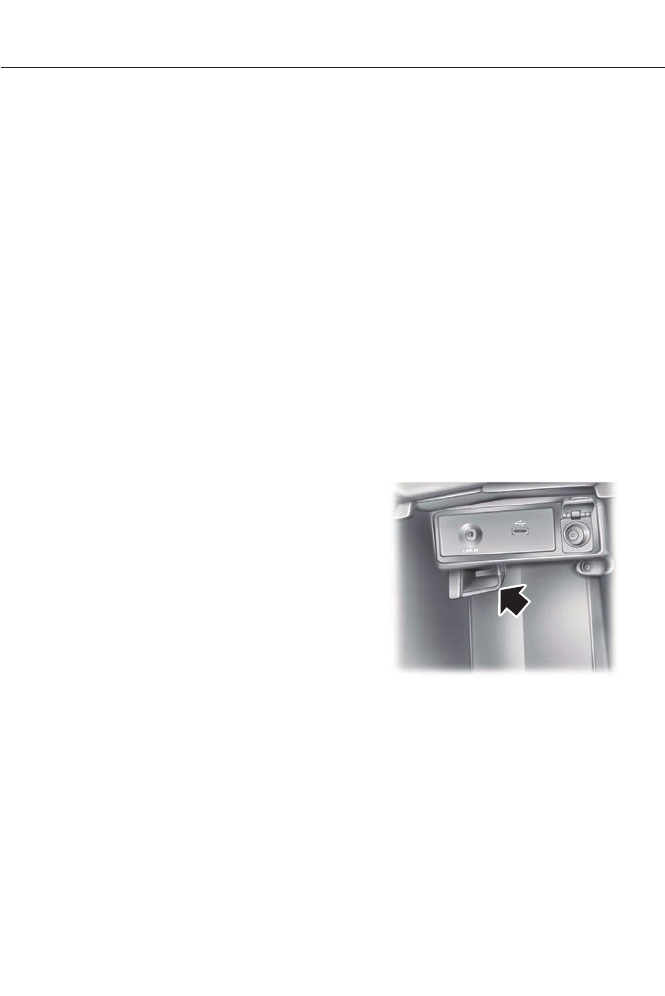
Anti-Scan Feature
The keypad will go into an anti-scan mode
if you enter the wrong code seven times
(35 consecutive button presses). This
mode disables the keypad for one minute
and the keypad lamp will flash.
The anti-scan feature will turn off after:
• one minute of keypad inactivity
• pressing the unlock button on the
remote control
• switching the ignition on
• unlocking your vehicle using intelligent
access.
Unlocking and Locking the Doors
To Unlock the Driver Door
Enter the factory-set 5-digit code or your
personal code. You must press each
number within five seconds of each other.
The interior lamps will illuminate.
Note: All doors will unlock if you enable the
all-door unlocking mode. See Locking and
Unlocking (page 52).
To Unlock All Doors
Enter the factory-set code or your personal
code, then press 3·4 within five seconds.
To Lock All Doors
Press and hold 7·8 and 9·0 at the same
time (with the driver door closed). You do
not need to enter the keypad code first.
To Release the Trunk
Enter the factory-set code or your personal
code, then press 5·6 within five seconds.
Displaying the Factory Set Code
With Integrated Keyhead Transmitters
Note: You will need to have two
programmed passive anti-theft keys for this
procedure.
To display the factory-set code in the
information display:
1. Insert a key into the ignition and switch
the ignition on for a few seconds.
2. Switch the ignition off and remove the
key.
3. Insert the second key into the ignition
and switch the ignition on.
The factory-set code will display for a few
seconds.
Note: The code may not display until after
any other warning messages first display.
With Intelligent Access Keys
Note: You will need to have two
programmed intelligent access keys for this
procedure.
To display the factory-set code in the
information display:
E147165
1. Place the first programmed key in the
backup slot inside the center console.
The key ring must be at the top with
the buttons facing toward the rear.
2. Press the START/STOP button once
and wait a few seconds.
3. Press the START/STOP button again
and remove the key.
4. Insert the second programmed key into
the backup slot, then press the
START/STOP button.
57
Locks
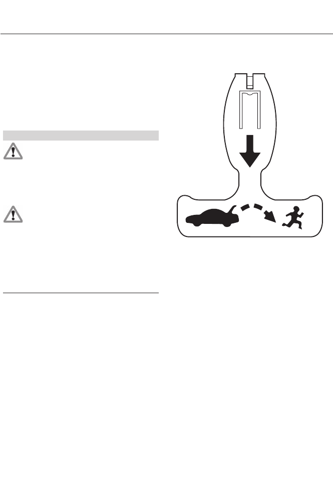
The factory-set code will appear in the
information display for a few seconds.
Note: The code may not display until after
any other warning messages first display.
INTERIOR LUGGAGE
COMPARTMENT RELEASE
WARNINGS
Keep vehicle doors and luggage
compartment locked and keep keys
and remote transmitters out of a
child’s reach. Unsupervised children could
lock themselves in the trunk and risk injury.
Children should be taught not to play in
vehicles.
Do not leave children, unreliable
adults, or animals unattended in the
vehicle. On hot days, the
temperature in the trunk or vehicle interior
can rise very quickly. Exposure of people
or animals to these high temperatures for
even a short time can cause death or
serious heat-related injuries, including brain
damage. Small children are particularly at
risk.
Your vehicle is equipped with a release
handle that provides a means of escape
for children and adults if they become
locked inside the luggage compartment.
Adults should familiarize themselves with
the operation and location of the release
handle.
E144403
The handle is located inside the luggage
compartment either on the luggage
compartment door (lid) or near the tail
lamps. It is composed of a material that
will glow for hours in darkness following
brief exposure to ambient light.
Pull the handle and push up on the luggage
compartment door (lid) to open from
within the luggage compartment.
58
Locks

PASSIVE ANTI-THEFT
SYSTEM
Note: The system is not compatible with
non-Ford aftermarket remote start systems.
Use of these systems may result in vehicle
starting problems and a loss of security
protection.
Note: Metallic objects, electronic devices
or a second coded key on the same key
chain may cause vehicle starting problems
if they are too close to the key when starting
the engine. Prevent these objects from
touching the coded key while starting the
engine. Switch the ignition off, move all
objects on the key chain away from the
coded key and restart the engine if a
problem occurs.
Note: Do not leave a duplicate coded key
in the vehicle. Always take your keys and
lock all doors when leaving the vehicle.
SecuriLock®
The system is an engine immobilization
system. It is designed to help prevent the
engine from starting unless you use a
coded key programmed to your vehicle.
Using the wrong key may prevent the
engine from starting. A message may
appear in the information display.
If you are unable to start the engine with a
correctly coded key, a malfunction has
happened and a message may appear in
the information display.
Automatic Arming
The vehicle arms immediately after
switching the ignition off.
Automatic Disarming
Switching the ignition on with a coded key
disarms the vehicle.
Replacement Keys
Note: Your vehicle comes equipped with
two integrated keyhead transmitters or two
intelligent access keys.
The integrated keyhead transmitter
functions as a programmed ignition key
that operates all the locks and starts the
vehicle, as well as a remote control.
The intelligent access key functions as a
programmed key that operates the driver
door lock and activates the intelligent
access with push button start system, as
well as a remote control.
If your programmed transmitters or
standard SecuriLock coded keys
(integrated keyhead transmitters only) are
lost or stolen and you do not have an extra
coded key, you will need to have your
vehicle towed to an authorized dealer. The
key codes need to be erased from your
vehicle and new coded keys will need to
be programmed.
Store an extra programmed key away from
the vehicle in a safe place to help prevent
any inconveniences. See your authorized
dealer to purchase additional spare or
replacement keys.
Programming a Spare Integrated
Keyhead Transmitter
Note: You can program a maximum of eight
coded keys to your vehicle. All eight can be
integrated keyhead transmitters.
You can program your own integrated
keyhead transmitter or standard
SecuriLock coded keys to your vehicle. This
procedure will program both the engine
immobilizer keycode and the remote entry
portion of the remote control to your
vehicle.
Only use integrated keyhead transmitters
or standard SecuriLock keys.
59
Security
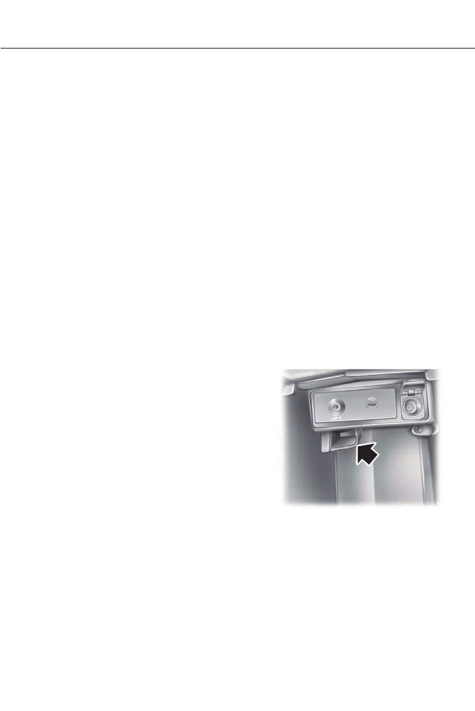
You must have two previously
programmed coded keys and the new
unprogrammed key readily accessible. See
an authorized dealer to have the spare key
programmed if two previously
programmed coded keys are not available.
Read and understand the entire procedure
before you begin.
1. Insert the first previously programmed
coded key into the ignition.
2. Switch the ignition from off to on. Keep
the ignition on for at least three
seconds, but no more than 10 seconds.
3. Switch the ignition off and remove the
first coded key from the ignition.
4. After three seconds but within 10
seconds of switching the ignition off,
insert the second previously coded key
into the ignition.
5. Switch the ignition from off to on. Keep
the ignition on for at least three
seconds, but no more than 10 seconds.
6. Switch the ignition off and remove the
second previously programmed coded
key from the ignition.
7. After three seconds but within 10
seconds of switching the ignition off
and removing the previously
programmed coded key, insert the new
unprogrammed key into the ignition.
8. Switch the ignition from off to on. Keep
the ignition on for at least six seconds.
9. Remove the newly programmed coded
key from the ignition.
If the key has been successfully
programmed it will start the engine and
operate the remote entry system (if the
new key is an integrated keyhead
transmitter).
If it was not programmed successfully,
wait 10 seconds and repeat Steps 1 through
8. If you are still unsuccessful, take your
vehicle to an authorized dealer.
Programming a Spare Intelligent
Access Key
Note: You can program a maximum for four
intelligent access keys to your vehicle.
You must have two previously
programmed intelligent access keys inside
your vehicle and the new unprogrammed
intelligent access keys readily accessible.
See an authorized dealer to have the spare
key programmed if two previously
programmed keys are not available.
Make sure that the vehicle is off before
beginning this procedure. Make sure that
you close all the doors before beginning
and that they remain closed throughout
the procedure. Perform all steps within 30
seconds of starting the sequence. Stop
and wait for at least one minute before
starting again if you perform any steps out
of sequence.
Read and understand the entire procedure
before you begin.
E147165
1. Place a programmed intelligent access
key in the backup slot in the center
console. The key ring must be at the
top with the buttons facing toward the
rear.
2. Wait 5 seconds, then press the
START/STOP button.
3. Remove the intelligent access key.
60
Security

4. Within 10 seconds, place a second
programmed intelligent access key in
the backup slot and press the
START/STOP button.
5. Wait 5 seconds, then press the
START/STOP button again.
6. Remove the intelligent access key.
7. Wait 5 seconds, then place the
unprogrammed intelligent access key
in the backup slot and press the
START/STOP button.
Programming is now complete. Verify the
remote control functions operate and the
vehicle starts with the new intelligent
access key.
If programming was not successful, wait
10 seconds and repeat Steps 1 through 7.
If you are still unsuccessful, take your
vehicle to your authorized dealer.
ANTI-THEFT ALARM
The system will warn you of an
unauthorized entry to your vehicle. It will
be triggered if any door, the luggage
compartment or the hood is opened
without using the key, remote control or
keyless entry keypad.
The direction indicators will flash and the
horn will sound if unauthorized entry is
attempted while the alarm is armed.
Take all remote controls to an authorized
dealer if there is any potential alarm
problem with your vehicle.
Arming the Alarm
The alarm is ready to arm when there is
not a key in the ignition. Electronically lock
the vehicle to arm the alarm.
Disarming the Alarm
Disarm the alarm by any of the following
actions:
• Unlock the doors or luggage
compartment with the remote control
or keyless entry keypad.
• Switch the ignition on or start the
vehicle.
• Use a key in the driver’s door to unlock
the vehicle, then switch the ignition on
within 12 seconds.
Note: Pressing the panic button on the
remote control will stop the horn and signal
indicators, but will not disarm the system.
61
Security
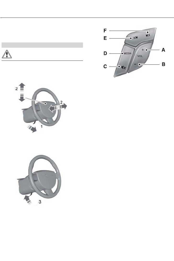
ADJUSTING THE STEERING
WHEEL
WARNING
Do not adjust the steering wheel
when your vehicle is moving.
Note: Make sure that you are sitting in the
correct position. See Sitting in the Correct
Position (page 117).
2
2
1
E157083
1. Unlock the steering column.
2. Adjust the steering wheel to the desired
position.
E157084
3. Lock the steering column.
AUDIO CONTROL (IF EQUIPPED)
You can operate the following functions
with the control:
E144503
Volume upA
Volume downB
MuteC
MediaD
Seek down or previousE
Seek up or nextF
MEDIA
Press repeatedly to scroll through available
audio sources.
Seek, Next or Previous
Press the seek button to:
• tune the radio to the next or previous
stored preset
• play the next or the previous track.
Press and hold the seek button to:
• tune the radio to the next station up or
down the frequency band
• seek through a track.
62
Steering Wheel
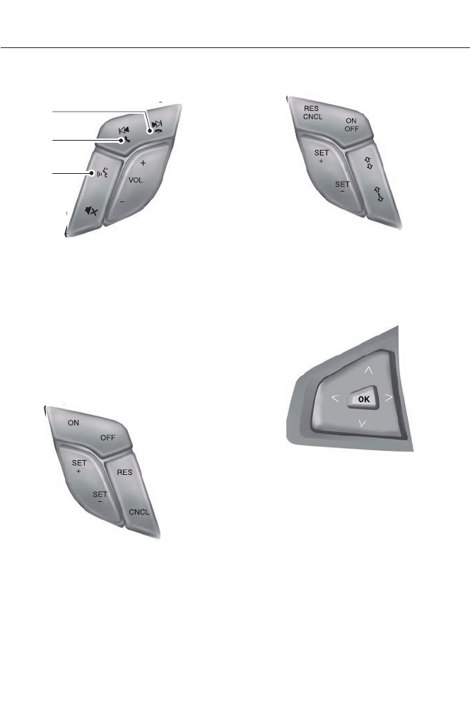
VOICE CONTROL (IF EQUIPPED)
B
A
C
E144504
End a callA
Answer a callB
Voice recognitionC
See SYNC™ (page 310). See MyFord
Touch™ (page 348).
CRUISE CONTROL
Type 1
E144500
Type 2
E144501
See Cruise Control (page 181).
INFORMATION DISPLAY
CONTROL
E144636
See Information Displays (page 84).
63
Steering Wheel

Cluster Display Control Features
E144811
If equipped with:
MyFord system: This control functions
the same as the center control on the
faceplate. See (page 297).
MyFord Touch: Use this control to adjust
the right side of the cluster display.
Navigate through the screen and press OK
to select. See MyFord Touch™ (page
348).
64
Steering Wheel
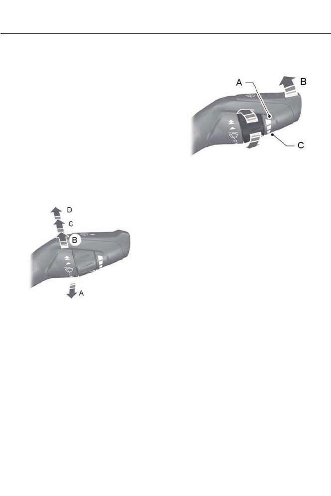
WINDSHIELD WIPERS
Note: Fully defrost the windshield before
switching on the windshield wipers.
Note: Make sure the windshield wipers are
switched off before entering a car wash.
Note: Clean the windshield and wiper
blades if they begin to leave streaks or
smears. If that doesn't resolve the issue,
install new wiper blades.
Note: Do not operate the wipers on a dry
windshield. This may scratch the glass,
damage the wiper blades or cause the wiper
motor to burn out. Always use the
windshield washers before wiping a dry
windshield.
E144495
Single wipeA
Intermittent wipeB
Normal wipeC
High speed wipeD
Intermittent Wipe
E144496
Shortest wipe intervalA
Intermittent wipeB
Longest wipe intervalC
Use the rotary control to adjust the
intermittent wipe interval.
Speed Dependent Wipers
When your vehicle speed increases, the
interval between wipes will decrease.
AUTOWIPERS (IF EQUIPPED)
Note: Fully defrost the windshield before
switching on the windshield wipers.
Note: Make sure the windshield wipers are
switched off before entering a car wash.
Note: Clean the windshield and wiper
blades if they begin to leave streaks or
smears. If that does not resolve the issue,
install new wiper blades.
Note: If you switch autolamps on in
conjunction with autowipers, your low beam
headlamps will illuminate automatically
when the rain sensor activates the
windshield wipers continuously.
65
Wipers and Washers
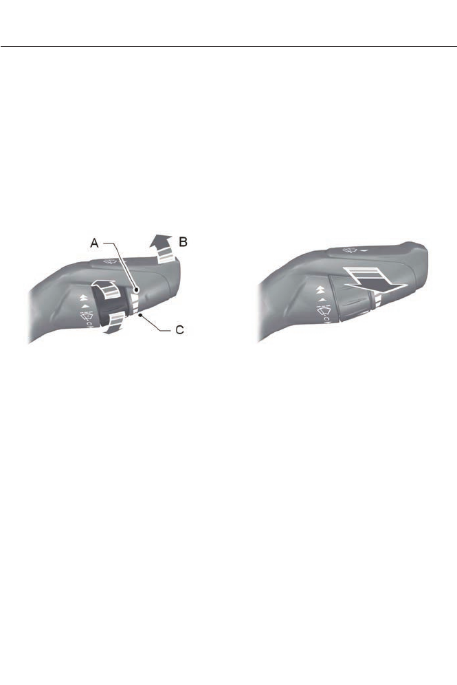
Note: Wet or winter driving conditions with
ice, snow or salty road mist can cause
inconsistent and unexpected wiping or
smearing.
In these conditions, you can do the
following to help keep your windshield
clear:
• Lower the sensitivity of the autowipers.
• Change the wiper speed to normal or
high speed wipe as necessary.
• Switch the autowipers off.
E144497
Highest sensitivityA
OnB
Lowest sensitivityC
The wipers will function when moisture is
detected on the windshield. The rain
sensor will continue to monitor the amount
of moisture on the windshield and adjust
the speed of the wipers automatically. This
feature can be switched on or off in the
information display. See General
Information (page 84).
Use the rotary control to adjust the
sensitivity of the rain sensor. With low
sensitivity, the wipers will operate when
the sensor detects a large amount of
moisture on the windshield. With high
sensitivity, the wipers will operate when
the sensor detects a small amount of
moisture on the windshield.
Keep the outside of the windshield clean.
Sensor performance will be affected if the
area around the interior mirror is dirty. The
rain sensor is very sensitive and the wipers
may operate if dirt, mist or flies hit the
windshield.
WINDSHIELD WASHERS
Note: Do not operate the washers when
the washer reservoir is empty. This may
cause the washer pump to overheat.
E144498
To operate the washers and spray the
windshield, pull the lever toward you.
A wipe will occur a few seconds after
washing to clear any remaining washer
fluid. This feature can be switched on or
off in the information display. See General
Information (page 84).
66
Wipers and Washers
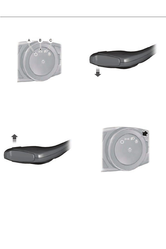
LIGHTING CONTROL
E142449
OffA
Parking lamps, instrument panel
lamps, license plate lamps and
tail lamps
B
HeadlampsC
High Beams
E162679
Push the lever forward to switch the high
beams on.
Push the lever forward again or pull the
lever toward you to switch the high beams
off.
Headlamp Flasher
E162680
Pull the lever toward you slightly and
release it to flash the headlamps.
AUTOLAMPS (IF EQUIPPED)
Note: It may be necessary to switch your
headlamps on manually in severe weather
conditions.
E142451
The headlamps will switch on and off
automatically in low light situations or
during inclement weather.
The headlamps will remain on for a period
of time after you switch the ignition off.
You can adjust the time delay using the
information display controls. See
Information Displays (page 84).
67
Lighting
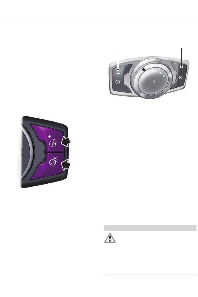
Note: If you switch autolamps on in
conjunction with autowipers, low beam
headlamps will illuminate automatically
when the rain sensor activates the
windshield wipers continuously.
INSTRUMENT LIGHTING
DIMMER
Note: If you disconnect the battery or it
becomes discharged, the illuminated
components will switch to the maximum
setting.
Vehicles With Front Fog Lamps
E132712
Press repeatedly or press and hold until
the desired level is reached.
Vehicles Without Front Fog Lamps
A B
A
E142452
Press repeatedly or press and
hold to dim.
A
Press repeatedly or press and
hold to brighten.
B
HEADLAMP EXIT DELAY
After you switch the ignition off, you can
switch the headlamps on by pulling the
direction indicator lever toward you. You
will hear a short tone. The headlamps will
switch off automatically after three
minutes with any door open or 30 seconds
after the last door has been closed. You
can cancel this feature by pulling the
direction indicator toward you again or
switching the ignition on.
DAYTIME RUNNING LAMPS (IF
EQUIPPED)
WARNING
Always remember to switch your
headlamps on in low light situations
or during inclement weather. The
system does not activate the tail lamps
and may not provide adequate lighting
during these conditions. Failure to activate
your headlamps under these conditions
may result in a collision.
68
Lighting
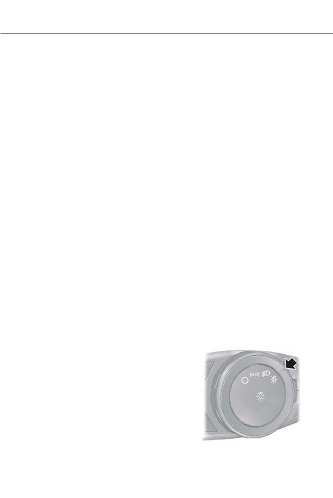
The system switches the low beam
headlamps on at a reduced intensity in
daylight conditions.
To switch the system on, switch the
ignition on, and switch the lighting control
to the off, autolamp or parking lamp
position.
AUTOMATIC HIGH BEAM
CONTROL (IF EQUIPPED)
The system will automatically turn on your
high beams if it is dark enough and no other
traffic is present. When it detects an
approaching vehicle’s headlights, a
preceding vehicle’s tail lamps or street
lighting, the system will turn off the high
beams before they distract other drivers.
The low beams remain on.
Note: If it appears that automatic control
of the high beams is not functioning
properly, check the windshield in front of
the camera for blockage. A clear view of the
road is required for proper system operation.
Any windshield damage in the area of the
camera field-of-view should be repaired.
Note: If a blockage is detected (e.g. bird
dropping, bug splatter, snow, or ice) and no
changes are observed, the system will go
into low beam mode until the blockage is
cleared. A message may also appear in the
instrument cluster display noting the front
camera is blocked.
Note: Typical road dust, dirt and water
spots will not affect the automatic high
beam system’s performance. However, in
cold or inclement weather conditions, the
automatic high beam system's availability
may be decreased, especially at startup. If
you want to change the beam state
independently of the system, you may turn
the high beams ON or OFF using the
multifunction switch lever. Automatic
control will resume when conditions are
correct.
Note: Modification of the vehicle ride height
(e.g. using much larger tires) may degrade
feature performance.
A camera sensor is centrally mounted
behind the windshield of the vehicle, and
monitors conditions continuously to decide
when to switch the high beams off and on.
Once the system is active, the high beams
will switch on if:
• The ambient light level is low enough
that high beams are needed.
• There is no traffic in front of the vehicle.
• The vehicle speed is greater than
25 mph (40 km/h).
The high beams will switch off if:
• An approaching vehicle's headlights or
a preceding vehicle's tail lamps are
detected.
• Vehicle speed falls below 16 mph
(25 km/h).
• The ambient light level is high enough
that high beams are not required.
• Severe rain, snow, or fog is detected.
• The camera is blocked.
Activating the System
Switch on the system using the information
display and autolamps. See Information
Displays (page 84). See Autolamps
(page 67).
E142451
69
Lighting
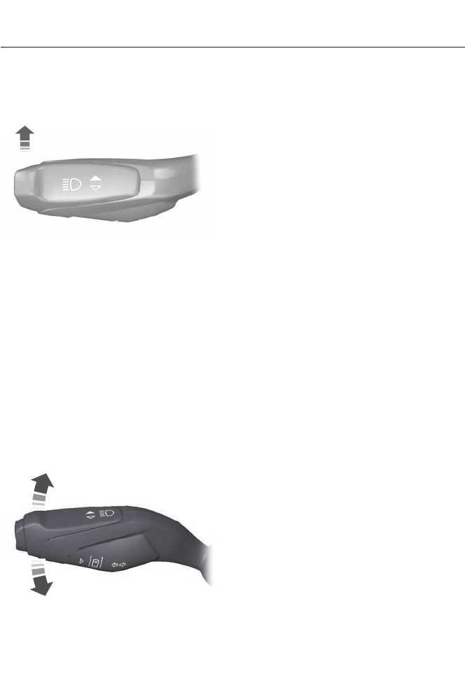
Turn the lighting control to the autolamps
position.
Manually Overriding the System
E130140
When the automatic control has activated
the high beams, pushing or pulling the stalk
will provide a temporary override to low
beam.
To permanently deactivate the system,
use the information display menu or turn
the lighting control switch from autolamps
to headlamps.
FRONT FOG LAMPS (IF EQUIPPED)
The fog lamps are turned on when the
lighting control is in the low beam position.
DIRECTION INDICATORS
E145595
Push the lever up or down to use the
direction indicators.
Note: Tap the lever up or down to make the
direction indicators flash three times to
indicate a lane change.
INTERIOR LAMPS
The lamps will switch on when one of the
following conditions have been met:
• You open any door.
• You press a remote control button.
• You touch switch A on the front interior
lamp.
Front Interior Lamp
Note: The front interior lamp switches are
on the overhead console. The exact location
of each switch on the overhead console
depends upon which roof, sunroof, and
window shade features are equipped on the
vehicle.
Note: Touch switch C to switch the door
function off when you open any door. The
indicator lamp will illuminate amber when
the door function is off. When the door
function is off and you open a door, the
courtesy and door lamps will stay off. Touch
switch C again to switch the door function
back on. The indicator lamp will illuminate
blue when the door function is on. When the
door function is on and you open a door, the
courtesy and door lamps will switch on.
70
Lighting
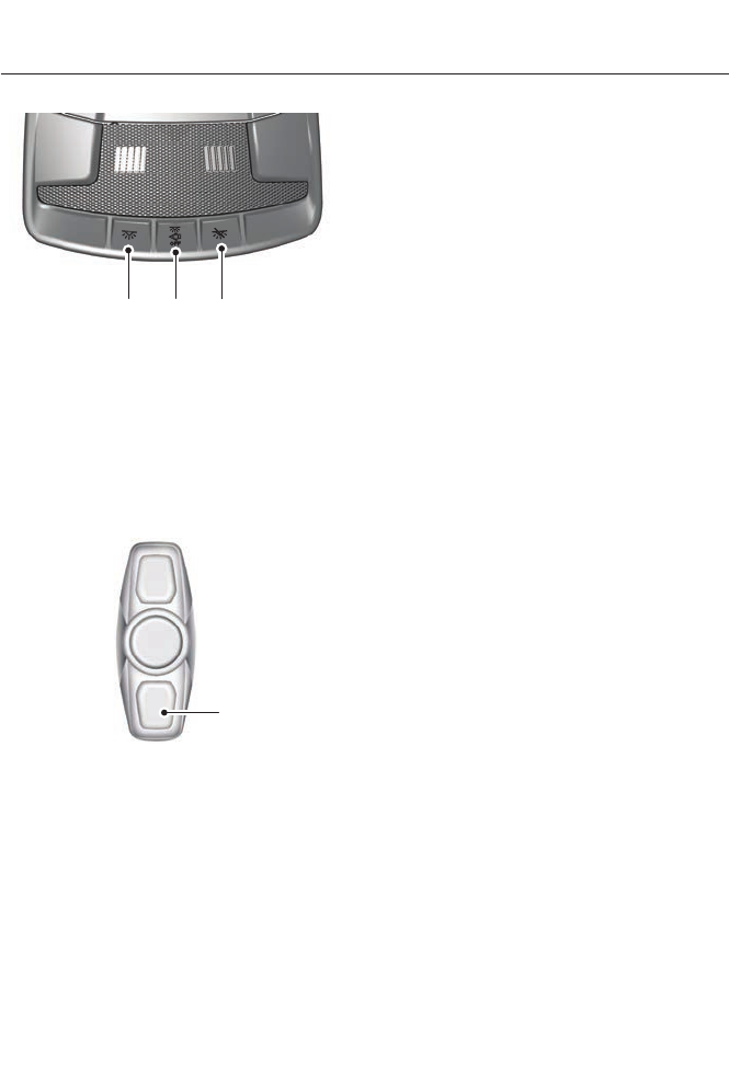
A B C
E146410
All lamps on switchA
All lamps off switchB
Door function switchC
You can switch individual map lamps on
independently by touching a map lens.
Rear Interior Lamp (If Equipped)
A
E142455
You can switch individual dome lamps on
independently by pressing switch A.
71
Lighting
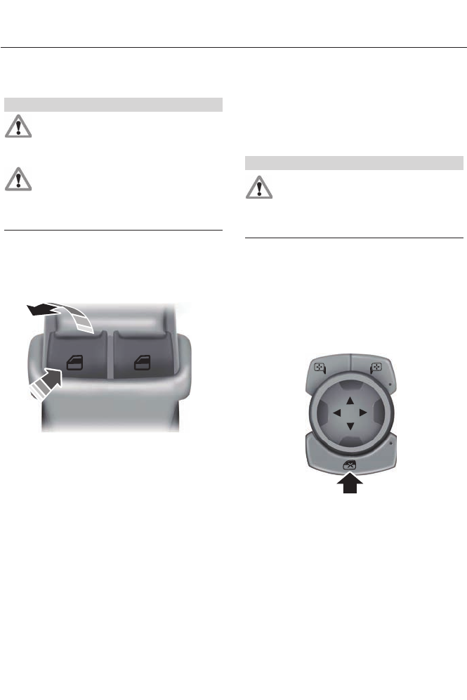
POWER WINDOWS
WARNINGS
Do not leave children unattended in
your vehicle and do not let them play
with the power windows. They may
seriously injure themselves.
When closing the power windows,
you should verify they are free of
obstructions and make sure that
children and pets are not in the proximity
of the window openings.
Note: During low battery conditions and
engine re-cranking, window operation may
be delayed or stop until after the engine
starts.
E146043
Note: You may hear a rumbling noise when
just one of the windows are open. Lower the
opposite window slightly to reduce this
noise.
Press the switch to open the window.
Lift the switch to close the window.
One-Touch Down
Press the switch fully and release it. Press
again or lift it to stop the window.
One-Touch Up
Lift the switch fully and release it. Press or
lift it again to stop the window.
Bounce-Back
The window will stop automatically while
closing. It will reverse some distance if
there is an obstacle in the way.
Overriding the Bounce-Back Feature
WARNING
When you override the bounce-back
feature the window will not reverse
if it detects an obstacle. Take care
when closing the windows to avoid
personal injury.
Pull up the window switch and hold within
two seconds of the window reaching the
bounce-back position. The window will
travel up with no bounce-back protection.
The window will stop if you release the
switch before the window is fully closed.
Window Lock
E144072
Press the control to lock or unlock the rear
window controls. It will illuminate when
you lock the rear window controls.
Accessory Delay
You can use the window switches for
several minutes after you switch the
ignition off or until you open either front
door.
72
Windows and Mirrors
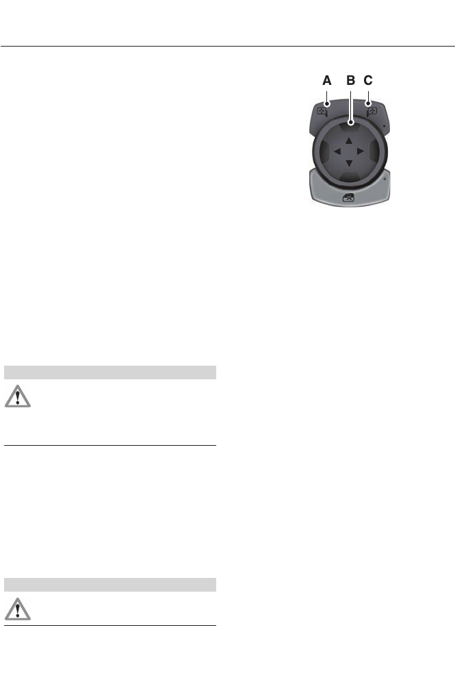
GLOBAL OPENING AND
CLOSING
You can use the remote control to operate
the windows with the ignition off.
Note: You can enable or disable this feature
in the information display or see an
authorized dealer. See General
Information (page 84).
Note: To operate this feature, accessory
delay must not be active.
Opening the Windows
You can only open the windows for a short
time after you unlock your vehicle with the
remote control. After you unlock your
vehicle, press and hold the remote control
unlock button to open the windows and
vent the moonroof. Release the button
once movement starts. Press the lock or
unlock button to stop movement.
Closing the Windows
WARNING
When closing the windows and
moonroof, you should verify they are
free of obstructions and make sure
that children and pets are not in the
proximity of the window openings.
To close the windows and moonroof, press
and hold the remote control lock button.
Release the button once movement starts.
Press the lock or unlock button to stop
movement.
EXTERIOR MIRRORS
Power Exterior Mirrors
WARNING
Do not adjust the mirrors when your
vehicle is moving.
E144073
Left-hand mirrorA
Adjustment controlB
Right-hand mirrorC
To adjust a mirror:
1. Select the mirror you want to adjust.
The control will illuminate.
2. Adjust the position of the mirror.
3. Press the mirror switch again.
Fold-Away Exterior Mirrors
Push the mirror toward the door window
glass. Make sure that you fully engage the
mirror in its support when returning it to its
original position.
Heated Exterior Mirrors (If Equipped)
See Heated Windows and Mirrors (page
115).
Memory Mirrors (If Equipped)
You can save and recall the mirror
positions through the memory function.
See Memory Function (page 120).
Auto-Dimming Feature (If Equipped)
The driver’s exterior mirror will
automatically dim when the interior
auto-dimming mirror is activated.
73
Windows and Mirrors
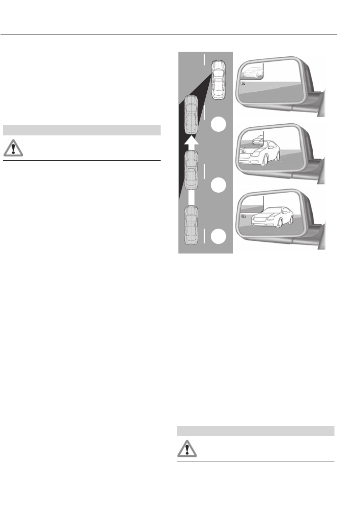
Signal Indicator Mirrors (If Equipped)
The outer portion of the appropriate mirror
housing will blink when the turn signal is
activated.
Integrated Blind Spot Mirrors (If
Equipped)
WARNING
Objects in the blind spot mirror are
closer than they appear.
Blind spot mirrors have an integrated
convex mirror built into the upper outboard
corner of the exterior mirrors. They are
designed to increase your visibility along
the side of your vehicle.
Check the main mirror first before a lane
change, then check the blind spot mirror.
If no vehicles are present in the blind spot
mirror and the traffic in the adjacent lane
is at a safe distance, signal that you intend
to change lanes. Glance over your shoulder
to verify traffic is clear and carefully
change lanes.
A
B
C
E138665
The image of the approaching vehicle is
small and near the inboard edge of the
main mirror when it is at a distance. The
image becomes larger and begins to move
outboard across the main mirror as the
vehicle approaches (A). The image will
transition from the main mirror and begin
to appear in the blind spot mirror as the
vehicle approaches (B). The vehicle will
transition to your peripheral field of view
as it leaves the blind spot mirror (C).
Blind Spot Monitor (If Equipped)
See Blind Spot Monitor (page 192).
INTERIOR MIRROR
WARNING
Do not adjust the mirror when your
vehicle is moving.
74
Windows and Mirrors
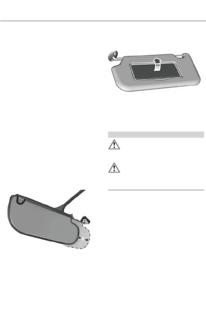
Note: Do not clean the housing or glass of
any mirror with harsh abrasives, fuel or other
petroleum or ammonia-based cleaning
products.
You can adjust the interior mirror to your
preference. Some mirrors also have a
second pivot point. This lets you move the
mirror head up or down and from side to
side.
Pull the tab below the mirror toward you
to reduce glare at night.
Auto-Dimming Mirror (If Equipped)
Note: Do not block the sensors on the front
and back of the mirror. Mirror performance
may be affected. A rear center passenger or
raised rear center head restraint may also
block light from reaching the sensor.
The mirror will dim automatically to reduce
glare when bright lights are detected from
behind your vehicle. It will automatically
return to normal reflection when you select
reverse gear to make sure you have a clear
view when backing up.
SUN VISORS
E138666
Rotate the sun visor toward the side
window and extend it rearward for extra
shade.
Illuminated Vanity Mirror
E162197
Lift the cover to switch the lamp on.
MOONROOF (IF EQUIPPED)
WARNINGS
Do not let children play with the
moonroof or leave them unattended
in the vehicle. They may seriously
hurt themselves.
When closing the moonroof, you
should verify that it is free of
obstructions and make sure that
children and pets are not in the proximity
of the roof opening.
The sliding shade can be manually opened
or closed when the moonroof is closed.
Pull the shade toward the front of the
vehicle to close it.
The moonroof controls are located on the
overhead console and have a one-touch
open and close feature. To stop it during
one-touch operation, touch the control a
second time.
75
Windows and Mirrors
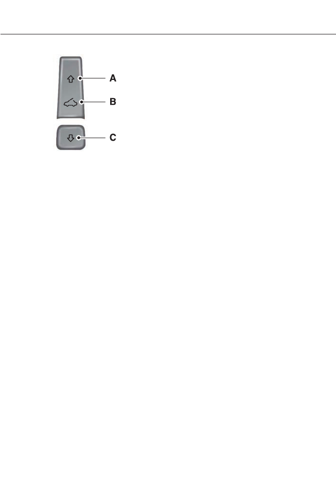
E144499
OpenA
VentB
CloseC
Opening and Closing the Moonroof
Touch (A) to open the moonroof. It will
stop short of the fully opened position.
Note: This position helps to reduce wind
noise or rumbling which may happen with
the moonroof fully open. Touch (A) again
to fully open the moonroof.
Touch (C) to close the moonroof.
Bounce-Back
The moonroof will stop automatically and
reverse some distance if an obstacle is
detected while closing.
Touch and hold (C) within two seconds of
a bounce-back event to override this
function.
Venting the Moonroof
Touch (B) to vent the moonroof. Touch
(C) to close it.
76
Windows and Mirrors
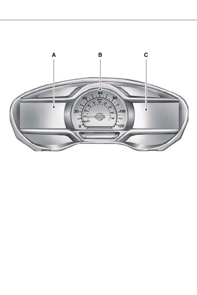
GAUGES
E151261
Left Information DisplayA
SpeedometerB
Right Information Display See General Information (page 348).C
Left Information Display
Odometer
Located in the bottom of the information
display Registers the accumulated
distance your vehicle has traveled.
Trip Computer
See General Information (page 84).
Vehicle Settings and Personalization
See General Information (page 84).
Common Displays
Note: Battery gauge information can be
individually selected on or off through
Battery Display in the Options sub-menu.
From any main display a right arrow press
on the steering wheel controls will take you
to the Options sub-menu.
77
Instrument Cluster

Note: For Energi vehicles there are two
versions of the battery gauge. When the
vehicle is in Hybrid Mode the information is
shown with a simple battery graphic. When
in Plug-in Power Mode an enhanced battery
graphic is provided and available electric
range is added to the display.
Battery Gauge:
The high voltage battery gauge appears
on the right side of the information display
screen. This provides Charge Fill (State of
Charge), Charge Assist and Regen Display.
• Charge Fill (Hybrid Mode) - The fill
level, or State of Charge indicates the
amount of energy stored in the high
voltage battery as a percent of total
energy capacity. The level will increase
or decrease as the battery charges and
discharges during normal operation,
but the hybrid system will attempt to
control the level to approximately the
middle of the gauge under most driving
conditions.
• Charge Fill (Energi Plug-in Power
Mode) - The fill level indicates the
amount of energy stored in the high
voltage battery which is available for
Plug-in Power Mode. A full fill
represents the total amount of energy
you can get from an external charge
(plugging your vehicle in). When the fill
reaches empty your vehicle will
automatically enter Hybrid Mode.
• Electric Range (Energi Plug-in Power
Mode) - The electric range estimate is
based on the amount of battery energy
currently available in the high voltage
battery and your typical energy usage
while driving. This includes your drive
habits as well as your use of
accessories such as Climate Control.
The battery energy refers to the energy
gained from charging the battery while
plugged in.
• Charge Assist - The up and down
arrows provide information about the
energy going into and out of the high
voltage battery. The up arrow above
the battery indicates battery charging
such as from regenerative braking. The
down arrow below the battery
indicates battery discharging to provide
power for propulsion or vehicle
accessories.
Note: The Charge Fill is always shown for
Plug-in Power Mode, even if Charge Fill is
not selected under Battery Display in the
Options sub-menu.
• Regen Display - A circular arrow
symbol appears in the center of the
Battery Gauge when energy is being
recaptured through the regenerative
braking system.
Fuel Gauge:
The fuel gauge will indicate approximately
how much fuel is left in the fuel tank. The
fuel gauge may vary slightly when your
vehicle is moving or on a gradient. The
arrow adjacent to the fuel pump symbol
indicates on which side of the vehicle the
fuel filler door is located.
78
Instrument Cluster

Brake Coach Display:
The Brake Coach appears after the vehicle
has come to a stop. It coaches you to brake
in a manner which maximizes the amount
of energy returned through the
regenerative braking system. The percent
displayed is an indication of the
regenerative braking efficiency with 100%
representing the maximum amount of
energy recovery.
Trip Summary and Lifetime Summary:
These will be displayed upon shutting off
the vehicle. Trip Summary will appear first,
then Lifetime Summary will be displayed.
You can toggle between these displays
using the up and down arrow keys on the
left hand steering wheel controls.
Trip Summary data is from the last power
cycle, while Lifetime Summary data is
cumulative from the last Lifetime
Summary reset done through the Settings
menu in the message center.
Trip Summary:
• Distance - The total distance traveled,
distance traveled on battery power
only (EV distance) and Regen distance
are displayed. Regen distance is the
estimated range gained from energy
recaptured through regenerative
braking.
• Energy Use - The average fuel economy
and total fuel used are displayed. In
addition for Energi, the total electrical
energy used while in Plug-in Power
Mode is displayed in kilowatt hours
(kWh). Trip Summary average fuel
economy will be shown in blue if better
than your lifetime average fuel
economy
• Brake Score - The average percentage
of braking energy recaptured and
returned to the high voltage battery
through regenerative braking. The
brake score will be shown in blue if
greater than (better than) the lifetime
brake score.
Lifetime Summary:
• Distance - The distance traveled on
battery power only (EV distance) and
Regen distance are displayed. Regen
distance is the estimated range gained
from energy recaptured through
regenerative braking.
• Energy Use - Average fuel economy.
• Brake Score - The average percentage
of braking energy recaptured and
returned to the high voltage battery
through regenerative braking.
79
Instrument Cluster
WARNING LAMPS AND
INDICATORS
The following warning lamps and
indicators will alert you to a vehicle
condition that may become serious. Some
lamps will illuminate when you start your
vehicle to make sure they work. If any
lamps remain on after starting your vehicle,
refer to the respective system warning
lamp for further information.
Note: Some warning indicators appear in
the information display and function the
same as a warning lamp but do not display
when you start your vehicle.
Adaptive Cruise Control (If Equipped)
E144524
The speed control system
indicator light changes color to
indicate what mode the system
is in: See Using Adaptive Cruise Control
(page 182).
On (white light): Illuminates when the
adaptive cruise control system is turned
on. Turns off when the speed control
system is turned off.
Engaged (green light): Illuminates when
the adaptive cruise control system is
engaged. Turns off when the speed control
system is disengaged.
Anti-Lock Braking System
If it illuminates when you are
driving, this indicates a
malfunction. You will continue
to have the normal braking system
(without ABS) unless the brake system
warning lamp is also illuminated. Have the
system checked by your authorized dealer.
Battery
If it illuminates while driving, it
indicates a malfunction. Switch
off all unnecessary electrical
equipment and have the system checked
by your authorized dealer immediately.
Blind Spot Monitor (If Equipped)
E151262
It will illuminate when you switch
this feature off or in conjunction
with a message. See Blind Spot
Monitor (page 192). See Information
Messages (page 96).
Brake System
E144522
It will illuminate when you
engage the parking brake with
the ignition on.
If it illuminates when you are driving, check
that the parking brake is not engaged. If
the parking brake is not engaged, this
indicates low brake fluid level or a brake
system malfunction. Have the system
checked immediately by your authorized
dealer.
WARNING
Driving your vehicle with the warning
lamp on is dangerous. A significant
decrease in braking performance
may occur. It will take you longer to stop
your vehicle. Have your vehicle checked by
your authorized dealer immediately. Driving
extended distances with the parking brake
engaged can cause brake failure and the
risk of personal injury.
Cruise Control (If Equipped)
E71340
It will illuminate when you switch
this feature on.
80
Instrument Cluster
Direction Indicator
Illuminates when the left or right
turn signal or the hazard warning
flasher is turned on. If the
indicators stay on or flash faster, check for
a burned out bulb. See Engine Oil
Dipstick (page 237).
Door Ajar
Displays when the ignition is on
and any door is not completely
closed.
Electric Park Brake
E146190
It will illuminate or flash when
the electric parking brake has a
malfunction.
Engine/Motor Coolant
Temperature
It will illuminate when the engine
or motor cooling system is
overheating. Stop the vehicle in
a safe place and contact your authorized
dealer.
Engine Oil
If it illuminates with the engine
running or when you are driving,
this indicates a malfunction.
Stop your vehicle as soon as it is safe to
do so and switch the engine off. Check the
engine oil level. See Engine Oil Check
(page 237).
Note: Do not resume your journey if it
illuminates despite the level being correct.
Have the system checked by your authorized
dealer immediately.
EV Now
E144814
It will illuminate when you select
this feature on. See Hybrid
Electric Vehicle (page 138).
EV Later
E151263
It will illuminate when you select
this feature on. See Hybrid
Electric Vehicle (page 138).
Fasten Safety Belt
It will illuminate and a chime will
sound to remind you to fasten
your safety belt. See Safety
Belt Minder (page 29).
Front Airbag
If it fails to illuminate when you
start your vehicle, continues to
flash or remains on, it indicates
a malfunction. Have the system checked
by your authorized dealer.
Front Fog Lamps (If Equipped)
It will illuminate when you switch
the front fog lamps on.
Grade Assist (If Equipped)
E144523
It will illuminate when the grade
assist function has been turned
on.
Heads Up Display (If Equipped)
E156133
A red beam of lights will
illuminate on the windshield in
certain instances when using
adaptive cruise control and/or the collision
warning system. It will also illuminate
momentarily when you start your vehicle
to make sure the display works.
81
Instrument Cluster
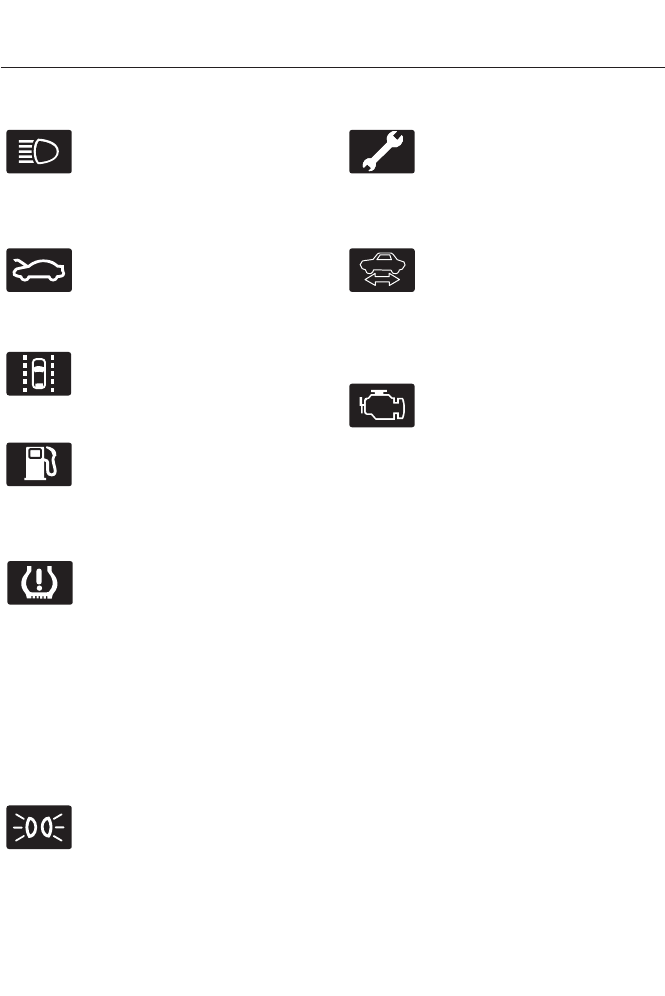
High Beam
It will illuminate when you switch
the high beam headlamps on. It
will flash when you use the
headlamp flasher.
Hood Ajar
E159324
Displays when the ignition is on
and the hood is not completely
closed.
Lane Keeping Aid (If Equipped)
E144813
Illuminates when the lane
keeping system is activated.
Low Fuel Level
It will illuminate when the fuel
level is low or the fuel tank is
nearly empty. Refuel as soon as
possible.
Low Tire Pressure Warning
It will illuminate when your tire
pressure is low. If the lamp
remains on with the engine
running or when driving, check
your tire pressure as soon as possible.
It will also illuminate momentarily when
you switch the ignition on to confirm the
lamp is functional. If it does not illuminate
when you switch the ignition on, or begins
to flash at any time, have the system
checked by your authorized dealer.
Parking Lamps
It will illuminate when you switch
the parking lamps on.
Powertrain Fault
Illuminates when a powertrain
fault has been detected. Contact
your authorized dealer as soon
as possible.
Ready to Drive
E144692
It will illuminate once the vehicle
has been switched on and is
ready to drive. A corresponding
message may display stating ready to
drive.
Service Engine Soon
If the service engine soon
indicator light stays illuminated
after the engine is started, it
indicates that the On Board Diagnostics
system (OBD) has detected a malfunction
of the vehicle emissions control system.
Refer to On board diagnostics (OBD) in
the Fuel and Refueling chapter for more
information about having your vehicle
serviced. See Emission Control System
(page 153).
If the light is blinking, engine misfire is
occurring which could damage your
catalytic converter. Drive in a moderate
fashion (avoid heavy acceleration and
deceleration) and have your vehicle
serviced immediately.
Note: Under engine misfire conditions,
excessive exhaust temperatures could
damage the catalytic converter or other
vehicle components.
The service engine soon indicator light
illuminates when the ignition is first turned
on prior to engine start to check the bulb
and to indicate whether the vehicle is ready
for Inspection/Maintenance (I/M) testing.
82
Instrument Cluster
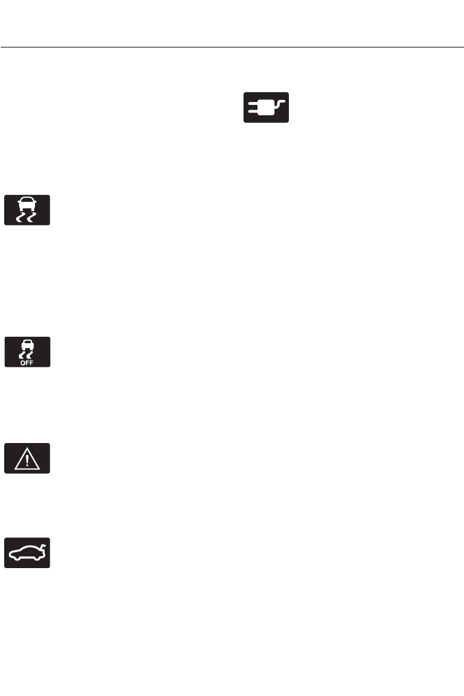
Normally, the service engine soon light will
stay on until the engine is cranked, then
turn itself off if no malfunctions are
present. However, if after 15 seconds the
service engine soon light blinks eight times,
it means that the vehicle is not ready for
I/M testing. See Emission Control
System (page 153).
Stability Control
E138639
It will flash when the system is
active. If it remains illuminated
or does not illuminate when you
switch the ignition on, this indicates a
malfunction. During a malfunction the
system will switch off. Have the system
checked by your authorized dealer
immediately. See Using Stability Control
(page 171).
Stability Control Off
It will illuminate when you switch
the system off. It will go out
when you switch the system
back on or when you switch the ignition
off. See Using Stability Control (page
171).
Stop Safely
E144693
Indicates electrical component
fault/failure that will cause the
vehicle to shutdown or enter into
a limited operating mode. A message may
also display.
Trunk Ajar
E159323
Displays when the ignition is on
and the trunk is not completely
closed.
Vehicle Plugged in (If Equipped)
E144694
It will illuminate when the vehicle
is plugged in. A corresponding
message may display after
attempting to start the vehicle.
AUDIBLE WARNINGS AND
INDICATORS
Key in Ignition Warning Chime
Sounds when you open the driver's door
and you have left the key in the ignition
with it in the off or accessory position.
Keyless Warning Alert (If Equipped)
Chirps the horn twice when you exit the
vehicle and the keyless vehicle is in RUN,
indicating the vehicle is still on.
Headlamps On Warning Chime
Sounds when you remove the key from the
ignition and open the driver's door and you
have left the headlamps or parking lamps
on.
Parking Brake On Warning Chime
Sounds when you have left the parking
brake on and drive your vehicle. If the
warning chime remains on after you have
released the parking brake, have the
system checked by your authorized dealer
immediately.
83
Instrument Cluster
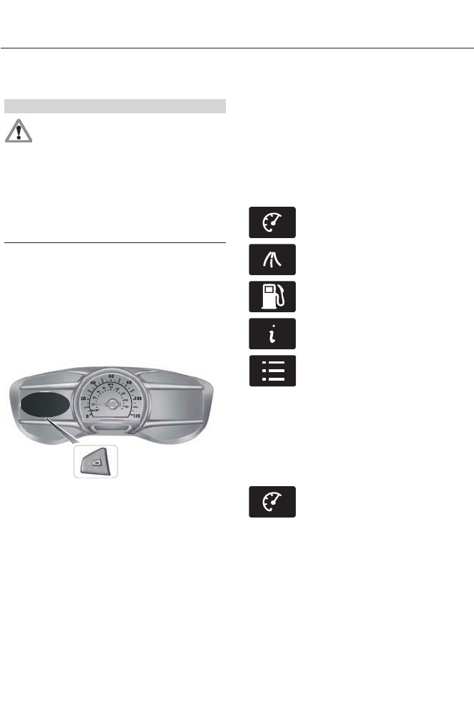
GENERAL INFORMATION
WARNING
Driving while distracted can result in
loss of vehicle control, accident and
injury. We strongly recommend that
you use extreme caution when using any
device or feature that may take your focus
off the road. Your primary responsibility is
the safe operation of the vehicle. We
recommend against the use of any
handheld device while driving and that you
comply with all applicable laws.
Various systems on your vehicle can be
controlled using the information display
controls on the steering wheel.
Corresponding information is displayed in
the information display.
Information Display Controls
E156010
• Press the up and down arrow buttons
to scroll through and highlight the
options within a menu.
• Press the right arrow button to enter a
sub-menu.
• Press the left arrow button to exit a
menu.
• Press and hold the left arrow button at
any time to return to the main menu
display (escape button).
• Press the OK button to choose and
confirm settings or messages.
Main menu
From the main menu bar on the left side
of the information display, you can choose
from the following categories:
E144639
Display Mode
E138660
Trip 1 & 2
E144640
Fuel Economy
E144642
Information
E100023
Settings
Scroll up or down to highlight one of the
categories, and then press the right arrow
key or OK to enter into that category. Press
the left arrow key as needed to exit back
to the main menu.
Display Mode
E144639
Use the up or down arrow
buttons to choose between the
following display options.
Note: The cluster will remember the menu
level 2 state when the individual key state
is changed from the RUN to the OFF
position.
84
Information Displays

Display Mode
Menu level 5Menu level 4Menu level 3Menu level 2
——Instantaneous FuelVehicle Range: HEV -
Range total PHEV -
Range for EV, Fuel and
Tota l
Yes / NoRegen ActiveBattery Display
Charge Assist
Charge Level
Help
——Help
——Instantaneous FuelInform: Avg Fuel
Economy + Battery
Gauge + Fuel Gauge Yes / NoRegen ActiveBattery Display
Charge Assist
Charge Level
Help
——Help
——Instantaneous FuelEnlighten: Power + Avg
Fuel Economy +
Battery Gauge + Fuel
Gauge
Yes / NoRegen ActiveBattery Display
Charge Assist
Charge Level
Help
——Help
——Instantaneous FuelEngage: Split Power +
Avg Fuel Economy +
Battery Gauge + Fuel
Gauge
Yes / NoRegen ActiveBattery Display
Charge Assist
Charge Level
Help
——Help
85
Information Displays
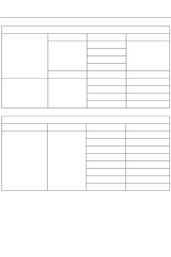
Display Mode
——Instantaneous FuelEmpower: Power (with
engine on/off
threshold) + Avg Fuel
Economy + Battery
Gauge + Fuel Gauge
Yes / NoRegen ActiveBattery Display
Charge Assist
Charge Level
Help
——Help
Average SpeedVehicle RangeChange MyViewMyView
Vehicle RangeAvg Fuel
Avg FuelPower
Inst. FuelSplit Power
Display Mode (cont'd)
Menu level 5Menu level 4Menu level 3Menu level 2
Coolant TempPower + ThresholdChange MyView
(cont'd)
MyView (cont'd)
Accessory PowerTach rpm x 1000
Trip 1Accessory Power
Trip 2Trip 1
Fuel HistoryTrip 2
CoachFuel History
BlankCoach
—Blank
86
Information Displays

Display Mode (cont'd)
Menu level 5Menu level 4Menu level 3Menu level 2
Yes / NoRegen ActiveBattery DisplayMyView (cont'd)
Charge Assist
Charge Level
Help
——Help
Yes / NoRegen ActiveBattery DisplayEnergi only
EV: Auto (consump-
tion gauge, accessory
power gauge)
Charge Assist
Charge Level
EV: Now (consump-
tion gauge with
budget cup, accessory
power gauge, over-
ride)
87
Information Displays

Display Mode (cont'd)
HelpEV: Later (consump-
tion gauge, accessory
power gauge, EV miles
reserved)
——Help
88
Information Displays

•Vehicle Range — Indicates the estimated distance the vehicle will travel with the
energy currently available. For Hybrid, the vehicle range estimate is based on the fuel
remaining in the gasoline tank. For Energi, the total estimated distance equals the
distance available in Hybrid Mode fueled by gasoline, plus the EV distance available
in Plug-in Power Mode. Changes in driving pattern may cause the values to vary.
• Instantaneous Fuel — This gauge is available on all Display mode screens and
shows the instantaneous fuel economy.
•Inform — Inform shows the fuel level, battery display and lifetime average fuel
economy, with options available for the Battery Display and an Instantaneous Fuel
Economy gauge. When the vehicle is operating on battery power only, EV is displayed.
•Enlighten — Enlighten displays power demand in addition to the typical information
and options from Inform. The Instantaneous Fuel Economy gauge will be displayed
by default. When the vehicle is operating on battery power only, EV is displayed and
the gauge fill is shown in blue. When both the engine and the electric motor are
providing power the gauge fill is white.
•Engage — Engage replaces the power demand gauge from Enlighten with separate
gauges for engine power and electric motor power. The engine power gauge fill is
white and the high voltage battery power gauge fill is blue. When the vehicle is
operating on battery power only, EV is displayed.
•Empower — Empower adds an engine on/off threshold to the power demand gauge
from Enlighten. The threshold is shown as a blue double outline. The gauge is designed
to show you how close you are to the gasoline engine on/off threshold and how much
power you are requesting by how much you press on the accelerator pedal.
When power demand is below the threshold the vehicle is operating on battery power
only, EV is displayed and the gauge fill is shown in blue.
When power demand exceeds the threshold both the engine and the high voltage battery
provide power and the gauge fill is white.
When power demand surpasses the amber indicator, this level of demand and associated
fuel economy are shown in amber.
MyView — You can choose what to display in this view. Selecting Change MyView in the
Options menu allows you to scroll through two columns of content choices.
• Avg Fuel — Indicates the average fuel consumption since the function was last reset.
• Power — When the transmission is in a drive gear only, this gauge shows you vehicle
power.
• Split Power— This gauge indicates the power being supplied by the vehicle’s two
power sources: the high voltage battery and the gasoline engine. When the hybrid
system is operating in electric vehicle mode (without the gasoline engine), EV is
displayed.
• Power + Threshold — When the transmission is in a drive gear only, this gauge shows
you vehicle power demand and gasoline engine on/off threshold. It is designed to
show you how close you are to the gasoline engine on/off threshold and how much
power you are requesting by how much you press on the accelerator pedal.
89
Information Displays

• Tach rpm x 1000 — When the gasoline engine is running, the tachometer gauge
displays the engine speed in revolutions per minute (RPM). When the vehicle is
operating on battery power only, EV is displayed and the tachometer is greyed out.
• Accessory Power— This gauge indicates electrical power demands from your vehicle’s
accessory systems. Accessories such as air conditioning, headlights, and radio use
power but do not contribute to propelling the vehicle. The higher the level indication
on this gauge, the more accessory power is being used. You can see the level of this
gauge change by turning accessories on and off.
• Battery Display — The high voltage battery display options include Regen Active,
Charge Assist and Charge Level.
• Regen Active — A circular arrow symbol appears over the center of the battery when
energy is being recaptured through the regenerative braking system.
• Charge Assist — An arrow above the battery indicates the battery is being charged;
an arrow below the battery indicates that battery power is being used for propulsion
or to power the vehicle accessories.
• Charge Level — This indicates the State of Charge of the battery. Additionally, for
Energi vehicles the option only applies for the Hybrid Mode battery display (simple
battery graphic). The Plug-in Power Mode battery will always show the charge level
with associated remaining EV range.
• Inst. Fuel — Shows instantaneous fuel usage.
• Coolant Temp – Indicates engine coolant temperature. At normal operating
temperature, the level indicator will be white and will be in the normal range (between
“H” and “C”). If the engine coolant temperature exceeds the normal range, the level
indicator will change to red to indicate that the engine is overheating. Stop the vehicle
as soon as safely possible, turn off the vehicle and let the engine cool.
The thermometer indicator next to the gauge will illuminate in blue or white to indicate
the following:
• Blue thermometer - This indicates that the hybrid system is not warm enough to allow
EV operation. The gasoline engine will run continuously when the indicator is blue.
During silent key start mode, the thermometer indicator will be blue, but the gasoline
engine will not run. This is the result of the vehicle computer allowing the engine to
be cooler during the silent key start period. This is normal operation and does not
indicate a problem with your vehicle. After the first engine start the indicator will turn
white when the gasoline engine is warm enough to turn off.
• White thermometer - This indicates that the hybrid system is warm enough to allow
EV operation. If the vehicle operates on battery power long enough, it is possible that
the gasoline engine may need to run to keep the system warm. In this case, the
thermometer indicator will revert back to blue.
Trip 1 & 2
E138660
Use the arrow buttons to choose
between the following.
Note: Pressing OK stops/starts the timer.
Holding OK resets the odometer and timer.
90
Information Displays

Trip 1 & 2
Menu level 5Menu level 4Menu level 3Menu level 2
—Elapsed trip timeStandardTrip 1 or Trip 2
—Trip distance
—EV distance
—Average fuel
economy
Enhanced
—Estimated amount
of fuel consumed
—Estimated amount
of electricity
consumed (Energi
only)
Yes / NoRegen ActiveBattery Display-
Charge Assist
Charge Level
Help
——Help
• Elapsed trip time — timer stops when the vehicle is turned off and restarts when the
vehicle is restarted.
• Trip distance — shows the accumulated trip distance.
• EV distance — shows the distance traveled while in electric only mode.
• Estimated amount of fuel consumed — shows the amount of fuel used for a given
trip.
• Estimated amount of electricity consumed — shows the amount of plug-in electricity
used for a given trip.
Fuel Economy
E144640
Use the arrow buttons to choose
the desired energy display.
91
Information Displays
Fuel Economy
Menu level 5Menu level 4Menu level 3Menu level 2
—1, 2, 6 min. IntervalsInterval TimeFuel History: Instant-
aneous Fuel
Economy + Fuel
Economy History +
Avg Fuel Economy
Yes / NoRegen ActiveBattery DisplayCoach
Charge Assist
Charge Level
Help
——Help
• Fuel History: This view from left to right starts with the instantaneous fuel economy
gauge and adds historical fuel economy data. The data is represented as an average
for time intervals of either 1, 2 or 6 minutes, with the left most interval being the most
recent. Total time for the 5 intervals is shown at the bottom of the view. Interval time
can be selected in the options sub menu. For Energi vehicles a blue outline indicates
Plug-in Power was used at least half of that interval. Intervals shown in grey color are
from the previous drive.
• Coach: This view provides a comparison of your recent Acceleration, Braking and
Cruising behavior to what is recommended for most efficient use of energy under
present conditions. The horizontal bars fill from left to right with best behavior (and
Blue color) shown as at least half full. When the bars are less than half full, the color
is Amber, suggesting that a change in behavior is needed to achieve better energy
efficiency.
Note that fuel economy is not always a measure of appropriate driving behavior. For
example, when driving uphill and maintaining an appropriate speed, your instant fuel
economy may not be good (losing leaves) but the Coach may show a blue bar for
Acceleration or Cruising.
Info
E144642
In this mode, you can view
different vehicle system
information and perform a
system check.
92
Information Displays
Information
Displays a number of different system tutorials. Use
the up or down arrows to scroll through the tutorials.
Then press OK to view.
TutorialWarnings
Displays the associated driver alert graphic.Driver Alert
MyKeys (Number of MyKeys programmed)MyKey
MyKey Miles (km) (Distance traveled using a
programmed MyKey)
Admin Keys (Number of admin keys)
All active warnings will display first if applicable. The
system check menu may appear different based upon
equipment options and current vehicle status. Use the
up or down arrow buttons to scroll through the list.
System
Check
Settings
E100023
In this mode, you can configure
different driver setting choices.
Note: Some items are optional and may
not appear.
Settings
Menu level 5Menu level 4Menu level 3Menu level 2
—On / OffTraction ControlDriver Assist
—On (default on key cycle)
/ Off
Blindspot
High / Normal / LowSensitivityCollision Warn
On / OffDistance Alert
On (default on key
cycle) / Off
Warn
—Adaptive / NormalCruise Control
—On (default on key cycle)
/ Off
Cross Traffic
93
Information Displays

Settings (cont’d)
Menu level 5Menu level 4Menu level 3Menu level 2
—On / OffECO CruiseDriver Assist
(cont’d) —On / OffDriver Alert
Alert / Aid / Alert +
Aid
ModeLane keeping Sys
High / Normal / LowIntensity
—On / OffEV + Mode
—On (default on key
cycle) / Off
Front Park Aid
—On (default on key
cycle) / Off
Rear Park Aid
—On (default on key
cycle) / Off
Auto Engine OffVehicle
—On / OffEasy Entry / Exit
On / OffAuto HighbeamLighting
Select time intervalAutolamp Delay
On / OffAutolockLocks
On / OffAutounlock
On / OffMislock
All doors / Driver
door
Remote Unlocking
Set to XXX %Oil Life Reset
Settings (cont’d)
Menu level 5Menu level 4Menu level 3Menu level 2
Heater: – A/C Auto / Last
Settings
Climate ControlRemote StartVehicle (cont’d)
Front Defrost: Auto / Off
Rear Defrost: Auto / Off
94
Information Displays

Settings (cont’d)
Driver Seat: Auto / Off
Passenger Seat: Auto /
Off
5 / 10 / 15 minutesDuration
On / OffQuiet Start
Enable / DisableSystem
Note: Some MyKey items will only appear if a MyKey is set.
Settings (cont’d)
Menu level 5Menu level 4Menu level 3Menu level 2
—On / OffSwitch InhibitVehicle (cont’d)
—Select number of yearsTire Mobility Kit
On / OffRemote OpenWindows
On / OffRemote Close
On / OffCourtesy WipeWipers
On / OffRain Sensing
—Hold OK to Create
MyKey
Create MyKeyMyKey
—Always On / User
Selectable
911 Assist
—Always On / User
Selectable
Traction Control
—Choose desired speed or
off
Max Speed
—Choose desired speed or
off
Speed Minder
—On / OffVolume Limiter
—On / OffDo Not Disturb
—Hold OK to Clear All
MyKeys
Clear MyKeys
95
Information Displays
Settings (cont’d)
—Select the desired
language
LanguageDisplay
Select the desired
units of measure
DistanceUnits
Fuel only / Fuel +
Electric
Fuel Economy
Fahrenheit (°F) /
Celsius (°C)
Temperature
—On / OffBrake Coach
Display
—Lifetime Fuel Economy,
Regen Miles, Brake
Score, Hold OK to
RESET
Liftetime
Summary
• Brake Coach Display: This appears after the vehicle has come to a stop. It coaches
you to brake in a manner which maximizes the amount of energy returned through
the regenerative braking system. The percent displayed is an indication of the
regenerative braking efficiency with 100% representing the maximum amount of
regenerative braking energy recovery.
INFORMATION MESSAGES
Note: Depending on the vehicle options
equipped with your vehicle, not all of the
messages will display or be available.
Certain messages may be abbreviated or
shortened depending upon which cluster
type you have.
E144636
Press the OK button to acknowledge and
remove some messages from the
information display. Other messages will
be removed automatically after a short
time.
Certain messages need to be confirmed
before you can access the menus.
96
Information Displays

Active Park
ActionMessage
Displayed when the system needs service. Contact your
authorized dealer as soon as possible.
Active Park Fault
Adaptive Cruise Control
ActionMessage
Displayed when a radar malfunction is preventing the ACC
from engaging. See Using Adaptive Cruise Control (page
182).
Adaptive Cruise
Malfunction
Displayed when conditions exist such that the adaptive cruise
cannot function properly. See Using Adaptive Cruise
Control (page 182).
Adaptive Cruise Not
Available
Displayed when the radar is blocked because of poor radar
visibility due to bad weather or ice/mud/water in front of
radar. Driver can typically clean the sensor to resolve. See
Using Adaptive Cruise Control (page 182).
Adaptive Cruise Not
Available Sensor
Blocked See Manual
Displayed when the automatic braking has been disabled.Cruise Control Auto-
matic Braking Turned
Off
Displayed when a radar malfunction is preventing the ACC
from engaging.
Front Sensor Not Aligned
Displayed when the adaptive cruise has reinstated controls
to the driver.
Adaptive Cruise - Driver
Resume Control
Displays when the vehicle speed is too slow to activate the
adaptive cruise.
Adaptive Cruise Speed
Too Low to Activate
AdvanceTrac™
ActionMessage
Displays when the system detects a malfunction due to a
blocked sensor.
Service AdvanceTrac
Displayed when the traction control has been disabled or
enabled by the driver.
AdvanceTrac Off On
97
Information Displays

Airbag
ActionMessage
Displays when the system detects a malfunction due to a
blocked sensor.
Occupant Sensor
BLOCKED Remove
Objects Near Passenger
Seat
Alarm
ActionMessage
Displays when the alarm has been triggered due to unauthor-
ized entry. See Anti-Theft Alarm (page 61).
Vehicle Alarm to Stop
Alarm, Start Vehicle
Automatic Engine Shutdown
ActionMessage
Displays when the engine is getting ready to shut off.Engine Shuts Off in XX
Seconds
Displays when the engine has shut off to help increase fuel
economy.
Engine Shut Off for Fuel
Economy
Displays when the engine is getting ready to shut off. You can
press OK on the left steering wheel button to override the shut
down.
Engine Shuts Off in XX
Seconds Press Ok to
Override
98
Information Displays

Battery and Charging System (12 volt)
ActionMessage
Stop your vehicle as soon as it is safe to do so and switch off
the ignition. Contact your authorized dealer.
Electrical System Over-
voltage Stop Safely
Displays to warn of a low battery condition. Turn off all
unneeded electrical accessories. Contact your authorized
dealer.
Battery low See manual
Displayed when the charging system needs servicing. If the
warning stays on or continues to come on, contact your
authorized dealer as soon as possible.
Check Charging System
Displayed when the battery management system detects an
extended low-voltage condition. Various vehicle features will
be disabled to help preserve the battery. Turn off as many of
the electrical loads as soon as possible to improve system
voltage. If the system voltage has recovered, the disabled
features will operate again as normal
Low Battery Features
Temporarily Turned Off
Displayed when the battery management system determines
that the battery is at a low state of charge. Turn the ignition
off as soon as possible to protect the battery. This message
will clear once the vehicle has been started and the battery
state of charge has recovered. Turning off unnecessary elec-
trical loads will allow faster battery state-of-charge recovery.
Turn Power Off to Save
Battery
Battery and Charging System (High Voltage)
ActionMessage
Displays when confirmation is needed that the vehicle is
unplugged before a start is allowed. You must make sure the
vehicle is unplugged and respond to the message prompt
before starting your vehicle.
Is Vehicle Plugged-In?
Displays when the stop safety hazard warning lamp is illumin-
ated. This indicates an electrical component fault/failure that
will cause the vehicle to shut down or enter into limited
operating mode.
Stop Safely Now
Displays when the vehicle is ready to drive.Ready to Drive
Displays when the vehicle detects it is still plugged in and the
power is activated.
Unplug Prior to Starting
Vehicle
99
Information Displays

Blind Spot Information and Cross Traffic Alert System
ActionMessage
Displayed when a fault with the system has occurred. Contact
your authorized dealer as soon as possible.
Blindspot System Fault
Displayed when the system sensors are blocked. Contact your
authorized dealer as soon as possible. See Blind Spot
Monitor (page 192).
Blindspot Not Available
Sensor Blocked See
Manual
Displayed when the system detects a vehicle. See Blind Spot
Monitor (page 192).
Cross Traffic Vehicle
Coming From X
Displayed when the system sensors are blocked. See Blind
Spot Monitor (page 192).
Cross Traffic Not Avail-
able Sensor Blocked See
Manual
Displays when a fault with the system has occurred. Contact
your authorized dealer as soon as possible.
Cross Traffic System
Fault
Collision Warning System
ActionMessage
Displayed when there is a system malfunction with the colli-
sion warning system. The system will be disabled. Contact
your authorized dealer as soon as possible.
Collision Warning
Malfunction
Displayed when the collision warning system radar is blocked
because of poor radar visibility due to bad weather or ice/
mud/water in front of the radar. Driver can typically clean the
sensor to resolve. Contact your authorized dealer as soon as
possible.
Collision Warning Not
Available Sensor
Blocked See Manual
Displayed when there is a system malfunction with the colli-
sion warning system. The system will be disabled. Contact
your authorized dealer as soon as possible.
Collision Warning Not
Available
100
Information Displays

Doors and Locks
ActionMessage
Displays when the door(s) listed is not completely closed and
the vehicle is moving.
X Door Ajar
Displays when the door(s) listed is not completely closed.
Displays when the luggage compartment is not completely
closed.
Trunk ajar
Displays when the door switches have been disabled.Switches Inhibited
Security Mode
Displayed when there is a system malfunction with the child
locks. Contact your authorized dealer as soon as possible.
Child Lock Malfunction
Service Required
Displays the factory keypad code after the keypad has been
reset.
Factory Keypad Code
XXXXX
Driver Alert
ActionMessage
Stop and rest as soon as it is safe to do so.Driver Alert Warning Rest
Now
Take a rest break soon.Driver Alert Warning Rest
Suggested
Fuel
ActionMessage
Displayed as an early reminder of a low fuel condition.Fuel Level Low
Displayed when the fuel fill inlet may not be properly closed.Check Fuel Fill Inlet
Displays when EV functionality is disabled and the engine is
running to maintain fuel freshness. See Fuel Quality (page
145).
Fuel Freshness
101
Information Displays

Hill Start Assist
ActionMessage
Displays when hill start assist is not available. Contact your
authorized dealer. See Hill Start Assist (page 164).
Hill Start Assist Not
Available
Keys and Intelligent Access
ActionMessage
Displayed as a reminder to press the brake while starting the
vehicle.
Press Brake to START
Displayed if the key is not detected by the system. See
Keyless Starting (page 132).
No Key Detected
Displayed when the start/stop button is pressed to shut off
the engine and an Intelligent Access key is not detected inside
the vehicle.
Restart Now or Key is
Needed
Displayed when the vehicle is in the run ignition state.Run Power Active
This message is displayed when there is a problem with your
vehicle’s starting system. See your authorized dealer for
service.
Starting System Fault
Displayed as a reminder to press the brake and clutch while
starting the vehicle.
Press Brake and Clutch
to Start
Displayed as a reminder to press the clutch in while starting
the vehicle.
Press Clutch to Start
Displayed during spare key programming, when an intelligent
access key is programmed to the system.
Key Program Successful
Displayed during spare key programming, when an intelligent
access key has failed to be programmed.
Key Program Failure
Displayed during spare key programming when the maximum
number of keys have been programmed.
Max Number of Keys
Learned
Displayed during spare key programming when not enough
keys have been programmed.
Not Enough Keys
Learned
Displays when the key battery is low. Change the battery as
soon as possible.
Key Battery Low Replace
Soon
Displayed when an attempt is made to program a spare key
using two existing MyKeys.
Could Not Program
Integrated Key
102
Information Displays

Lane Keeping System
ActionMessage
The system has malfunctioned. Contact your authorized
dealer as soon as possible.
Lane Keeping Sys.
Malfunction Service
Required
The system has detected a condition that has caused the
system to be temporarily unavailable.
Front Camera Tempor-
arily Not Available
The system has detected a condition that requires the wind-
shield to be cleaned to operate properly.
Front Camera Low Visib-
ility Clean Screen
The system has malfunctioned. Contact your authorized
dealer as soon as possible.
Front Camera Malfunc-
tion Service Required
Displayed when the system requests the driver to keep their
hands on the steering wheel.
Keep Hands on Steering
Wheel
Maintenance
ActionMessage
Stop the vehicle as soon as safely possible, turn off the engine.
Check the oil level. If the warning stays on or continues to
come on with your engine running, contact your authorized
dealer as soon as possible.
LOW Engine Oil Pressure
Displayed when the engine oil life remaining is 10% or less.
See Engine Oil Check (page 237).
Change Engine Oil Soon
Displayed when the oil life left reaches 0%. See Engine Oil
Check (page 237).
Oil Change Required
Indicates the brake fluid level is low and the brake system
should be inspected immediately. See Brake Fluid Check
(page 242).
Brake Fluid Level LOW
Displays when the brake system needs servicing. Stop the
vehicle in a safe place. Contact your authorized dealer.
Check Brake System
Displays when the engine coolant temperature is excessively
high.
Engine Coolant Overtem-
perature
Displays when the motor coolant temperature is excessively
high.
Motor Coolant Overtem-
perature
Displays when the engine has reduced power in order to help
reduce high coolant temperatures.
Power Reduced to
Lower Engine Temp
103
Information Displays

ActionMessage
Displayed when the kit needs service. See your authorized
dealer.
Service Tire Mobility Kit
Displays to indicate that the vehicle is still in Transport or
Factory mode. This may not allow some features to operate
properly. See your authorized dealer.
Transport / Factory
Mode
Informs the driver that the powertrain needs service due to a
powertrain malfunction.
See Manual
Displays when EV functionality is disabled and the engine is
running to maintain oil quality. See Engine Oil Check (page
237).
Oil Maintenance
MyKey
ActionMessage
Displayed during key programming when MyKey cannot be
programmed.
MyKey Not Created
Displays when MyKey is active.MyKey Active Drive
Safely
Displays when starting the vehicle and MyKey is in use and
the MyKey speed limit is on.
Speed Limited to XX
MPH/km/h
Displays when a MyKey is in use and the MyKey speed limit is
on and the vehicle speed is approaching 80 mph (130 km/h).
Near Vehicle Top Speed
Displays when a MyKey is in use and the MyKey speed limit is
reached.
Vehicle at Top Speed of
MyKey Setting
Displays when MyKey is active.Check Speed Drive
Safely
Displays when a MyKey is in use and Belt-Minder is activated.Buckle Up to Unmute
Audio
Displays when a MyKey is in use and AdvanceTrac is activated.AdvanceTrac On -
MyKey Setting
104
Information Displays

ActionMessage
Displays when a MyKey is in use and Traction control is
activated.
Traction Control On -
MyKey Setting
Displays when a MyKey is in use and park aid is activated.MyKey Park Aid Cannot
Be Deactivated
Displayed when the lane keeping aid is on per MyKey settings.Lane Keeping Alert On
MyKey Setting
Park Aid
ActionMessage
Displays when the system has detected a condition that
requires service. Contact your authorized dealer. See Parking
Aid (page 172).
Check Front Park Aid
Displays when the system has detected a condition that
requires service. Contact your authorized dealer. See Parking
Aid (page 172).
Check Rear Park Aid
Displays the park aid status.Front Park Aid On Off
Displays the park aid status.Rear Park Aid On Off
Park Brake
ActionMessage
Displays when the parking brake is set, the engine is running
and the vehicle is driven more than 3 mph (5 km/h). If the
warning stays on after the parking brake is released, contact
your authorized dealer.
Park Brake Engaged
The electric parking brake system has detected a condition
that requires service. See your authorized dealer.
Park Brake Malfunction
Service Now
Displays when the electric parking brake is not set.Park Brake Not Applied
Apply Park Brake
Displays when the electric parking brake did not set.Park Brake Not Applied
Re-Apply
Displays when the electric parking brake is running a diagnostic
check.
Park Brake Maintenance
Mode
105
Information Displays

ActionMessage
Displays when the electric parking brake is set, but has not
been released.
Park Brake Use Switch
to Release
Displays when the electric parking brake is set but has not be
released and the vehicle is moving.
Press Brake To Release
Park Brake
The electric park brake system has detected a condition that
requires service. See your authorized dealer.
Park Brake Limited
Function Service
Required
Displays when the electric parking brake was not released
causing it to overheat.
Park Brake System
Overheated
Displays when the electric parking brake is set and the vehicle
is started.
Release Park Brake
Displays when the electric parking brake is set.Park Brake Applied
Displays when the electric parking brake is released.Park Brake Released
Power Steering
ActionMessage
The power steering system has detected a condition that
requires service. See your authorized dealer.
Steering Fault Service
Now
The power steering system is not working. Stop the vehicle a
safe place. Contact your authorized dealer.
Steering Loss Stop
Safely
The power steering system has detected a condition within
the power steering system or passive entry or passive start
system requires service. Contact your authorized dealer.
Steering Assist Fault
Service Required
Remote Start
ActionMessage
Displays as a reminder to turn the key on to drive the vehicle
after a remote start.
To Drive: Turn Key to On
Displays as a reminder to apply the brake and the start button
to drive the vehicle after a remote start.
To Drive: Press Brake
and Start Button
106
Information Displays

Starting System
ActionMessage
Displays when starting the vehicle as a reminder to apply the
brake.
Press Brake + Start
Button
Displays when the starter has exceeded its cranking time in
attempting to start the vehicle.
Cranking Time Exceeded
Displays when the starter is attempting to start the vehicle.Engine Start Pending
Please Wait
Displays when the pending start has been cancelled.Pending Start Cancelled
Tire Pressure Monitoring System
ActionMessage
Displays when one or more tires on your vehicle have low tire
pressure. See Tire Pressure Monitoring System (page 280).
LOW Tire Pressure
Displays when the tire pressure monitoring system is
malfunctioning. If the warning stays on or continues to come
on, contact your authorized dealer. See Tire Pressure
Monitoring System (page 280).
Tire Pressure Monitor
Fault
Displayed when a tire pressure sensor is malfunctioning, or
your spare tire is in use. For more information on how the
system operates under these conditions, See Tire Pressure
Monitoring System (page 280). If the warning stays on or
continues to come on, contact your authorized dealer as soon
as possible.
Tire Pressure Sensor
Fault
Traction Control
ActionMessage
Displays when the traction control system has been switched
off or on. See Using Traction Control (page 170).
Traction Control Off/On
Displays when a spinout has occurred and the hazard are
activated.
Spinout Detected
Hazards Activated
107
Information Displays

Transmission
ActionMessage
See your authorized dealer.Transmission Malfunc-
tion Service Now
The transmission is overheating and needs to cool. Stop in a
safe place as soon as it’s possible.
Transmission Over-
heating Stop Safely
See your authorized dealer.Transmission Service
Required
Transmission is getting hot. Stop to let it cool.Transmission Too Hot
Press Brake
Displays when the transmission has overheated and has
limited functionality. See Automatic Transmission (page
162).
Transmission Limited
Function See Manual
Transmission is too cold. Wait for it to warm up before you
drive.
Transmission Warming
Up Please Wait
Displays as a reminder to shift into park.Shift to Park
Displays to request the operator to apply the brake as needed
by the transmission.
Press Brake Pedal
Displays when the transmission has adjusted the shift
strategy.
Transmission Adjusted
Displays when the transmission is adjusting the shift strategy.Transmission Adapt
Mode
Displays when the transmission shift lever is locked and unable
to select gears.
Transmission Indicate
Mode Lockup On
Displays when the transmission shift lever is unlocked and
free to select gears.
Transmission Indicate
Mode Lockup Off
Displays when the transmission shift lever has selected an
invalid gear.
Invalid Gear Selected
108
Information Displays
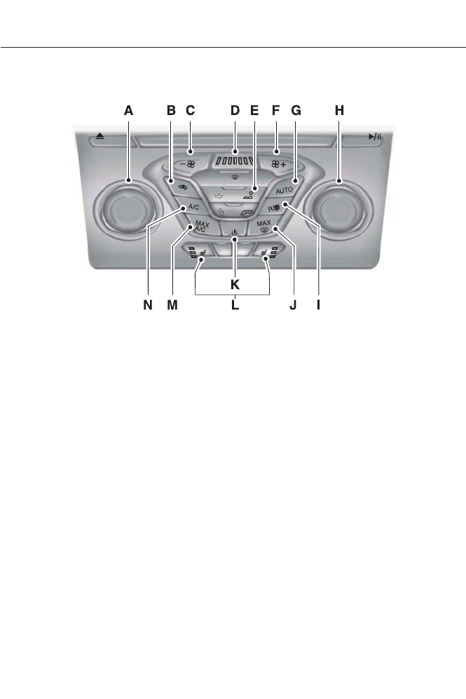
AUTOMATIC CLIMATE CONTROL (IF EQUIPPED)
E144492
Driver temperature control: Turn to increase or decrease the air temperature
for the driver side of the vehicle. This control also adjusts the passenger side
temperature when dual zone operation is disengaged.
A
Recirculated air: Press the button to switch between outside air and
recirculated air. When you select recirculated air, the air currently in the
passenger compartment recirculates. This may reduce the time needed to cool
the interior (when used with A/C) and may reduce unwanted odors from entering
your vehicle. Recirculated air may turn off automatically in all airflow modes
except MAX A/C to reduce the possibility of fogging.
B
- Fan speed control: Press to decrease the volume of air circulated in your
vehicle.
C
Fan speed indicator: Illuminates to indicate fan speed. When the system is
controlling the fan automatically, all of the fan speed indicators turn off.
D
Airflow distribution control: Press these buttons to turn airflow from the
windshield, instrument panel and footwell vents. The system can distribute air
through any combination of these air vents. At least one of these buttons
remains on while the system is on. When the system is controlling air distribution
automatically, indicators for all of these buttons turn off.
E
+ Fan speed control: Press to increase the volume of air circulated in your
vehicle.
F
109
Climate Control

AUTO: Press the button to turn on fully automatic operation. Select the desired
temperature using the temperature control. The system automatically adjusts
fan speed, air distribution, A/C operation, and outside or recirculated air, to heat
or cool the vehicle to maintain the selected temperature.
G
Passenger temperature control: Turn to increase or decrease the air
temperature on the passenger side of the vehicle.
H
Heated rear window: Turns the heated rear window on and off. See Heated
Windows and Mirrors (page 115).
I
MAX Defrost: Press to switch on. The system distributes outside air through
the windshield air vents, the air conditioning automatically turns on, and the
fan automatically adjusts to the highest speed. When MAX defrost is on,
recirculated air cannot be selected (to prevent fogging). The heated rear window
is automatically switched on when MAX defrost is selected.
J
Power: Press the button to turn the system off and on. When the system is off,
outside air cannot enter the vehicle.
K
Heated seat (if equipped): Turn the driver or passenger heated seats on and
off. See Heated Seats (page 123).
L
MAX A/C: Press the button to switch between outside air and recirculated air.
When you select recirculated air, the air currently in the passenger compartment
recirculates. This may reduce the time needed to cool the interior (when used
with A/C) and may reduce unwanted odors from entering your vehicle.
Recirculated air may turn off automatically in all airflow modes except MAX
A/C to reduce the possibility of fogging.
M
A/C: Press the button to turn air conditioning off and on. To improve air
conditioning when starting your vehicle, drive with the windows slightly open
for two to three minutes. Use A/C with recirculated air to improve cooling
performance and efficiency.
N
AUTOMATIC CLIMATE
CONTROL (IF EQUIPPED)
Note: You can switch temperature units
between Fahrenheit and Celsius. See
Settings (page 358).
110
Climate Control
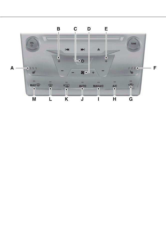
E144493
Driver heated seat control: Turn the driver heated seat off and on. See
Heated Seats (page 123).
A
Driver temperature control: Press + or - to increase or decrease the air
temperature for the driver side of the vehicle. This control also adjusts the
passenger side temperature when dual zone operation is disengaged.
B
Power: Press to turn the system off and on. When the system is off, outside
air cannot enter the vehicle.
C
Fan speed control: Press on either side of the fan icon to increase or decrease
the volume of air circulated in your vehicle.
D
Passenger temperature controls: Press + or - to increase or decrease the
air temperature for the passenger side of the vehicle.
E
Passenger heated seat control: Turn the passenger heated seat off and on.
See Heated Seats (page 123).
F
Recirculated air: Press the button to switch between outside air and
recirculated air. When you select recirculated air, the air currently in the
passenger compartment recirculates. This may reduce the time needed to cool
the interior (when used with A/C) and may reduce unwanted odors from entering
your vehicle. Recirculated air may turn off automatically in all airflow modes
except MAX A/C to reduce the possibility of fogging.
G
A/C: Press the button to turn air conditioning off and on. To improve air
conditioning when starting your vehicle, drive with the windows slightly open
for two to three minutes. Use A/C with recirculated air to improve cooling
performance and efficiency.
H
111
Climate Control

MAX A/C: Press the button to switch between outside air and recirculated air.
When you select recirculated air, the air currently in the passenger compartment
recirculates. This may reduce the time needed to cool the interior (when used
with A/C) and may reduce unwanted odors from entering your vehicle.
Recirculated air may turn off automatically in all airflow modes except MAX
A/C to reduce the possibility of fogging.
I
AUTO: Press the button to turn on fully automatic operation. Select the desired
temperature using the temperature control. The system automatically adjusts
fan speed, air distribution, A/C operation, and outside or recirculated air, to heat
or cool the vehicle to maintain the selected temperature.
J
Heated rear window: Turns the heated rear window on and off. See Heated
Windows and Mirrors (page 115).
K
Defrost: Distributes air through the windshield defroster vents and de-mister
vents. You can also use this setting to defog and clear the windshield of a thin
covering of ice.
L
MAX Defrost: Press to switch on. The system distributes outside air through
the windshield air vents, the air conditioning automatically turns on, and the
fan automatically adjusts to the highest speed. When MAX defrost is on,
recirculated air cannot be selected (to prevent fogging). The heated rear window
is automatically switched on when MAX defrost is selected.
M
AUTOMATIC CLIMATE
CONTROL (IF EQUIPPED)
Note: You can switch temperature units
between Fahrenheit and Celsius. See
Settings (page 358).
112
Climate Control
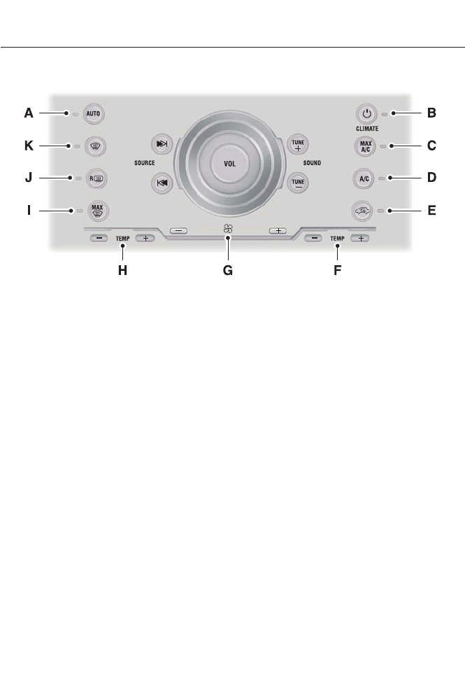
E144494
AUTO: Press the button to turn on fully automatic operation. Select the desired
temperature using the temperature control. The system automatically adjusts
fan speed, air distribution, A/C operation, and outside or recirculated air, to heat
or cool the vehicle to maintain the selected temperature.
A
CLIMATE: Press to turn the climate control system on and off. When the system
is off, outside air cannot enter the vehicle.
B
MAX A/C: Press the button to switch between outside air and recirculated air.
When you select recirculated air, the air currently in the passenger compartment
recirculates. This may reduce the time needed to cool the interior (when used
with A/C) and may reduce unwanted odors from entering your vehicle.
Recirculated air may turn off automatically in all airflow modes except MAX
A/C to reduce the possibility of fogging.
C
A/C: Press the button to turn air conditioning off and on. To improve air
conditioning when starting your vehicle, drive with the windows slightly open
for two to three minutes. Use A/C with recirculated air to improve cooling
performance and efficiency.
D
Recirculated air: Press the button to switch between outside air and
recirculated air. When you select recirculated air, the air currently in the
passenger compartment recirculates. This may reduce the time needed to cool
the interior (when used with A/C) and may reduce unwanted odors from entering
your vehicle. Recirculated air may turn off automatically in all airflow modes
except MAX A/C to reduce the possibility of fogging.
E
Passenger temperature control: Allows the passenger to set their
temperature independent of the driver temperature. Press + or - to increase or
decrease the air temperature on the passenger side of the vehicle when in dual
zone mode.
F
113
Climate Control

Fan speed control: Press the small fan icon or large fan icon to decrease or
increase the volume of air circulated in your vehicle.
G
Driver temperature control: Press + or - to increase or decrease the air
temperature inside the vehicle. This control also adjusts the passenger side
temperature when dual zone operation is disengaged.
H
MAX Defrost: Press to switch on. The system distributes outside air through
the windshield air vents, the air conditioning automatically turns on, and the
fan automatically adjusts to the highest speed. When MAX defrost is on,
recirculated air cannot be selected (to prevent fogging). The heated rear window
is automatically switched on when MAX defrost is selected.
I
Heated rear window: Turns the heated rear window on and off. See Heated
Windows and Mirrors (page 115).
J
Defrost: Distributes air through the windshield defroster vents and de-mister
vents. You can also use this setting to defog and clear the windshield of a thin
covering of ice.
K
HINTS ON CONTROLLING THE
INTERIOR CLIMATE
General Hints
Note: Prolonged use of recirculated air may
cause the windows to fog up.
Note: You may feel a small amount of air
from the footwell air vents regardless of the
air distribution setting.
Note: To reduce humidity build-up inside
your vehicle, do not drive with the system
switched off or with recirculated air always
switched on.
Note: Do not place objects under the front
seats as this may interfere with the airflow
to the rear seats.
Note: Remove any snow, ice or leaves from
the air intake area at the base of the
windshield.
Automatic Climate Control
Note: Adjusting the settings when your
vehicle interior is extremely hot or cold is
not necessary. The system automatically
adjusts to heat or cool the cabin to your
selected temperature as quickly as possible.
For the system to function efficiently, the
instrument panel and side air vents should
be fully open.
Note: At low ambient temperatures with
AUTO selected, the system directs airflow
to the windshield and side window vents
and fan may run at a slow speed until the
engine warms up.
Heating the Interior Quickly
1. Press the AUTO button.
2. Adjust the temperature control to the
desired setting.
Recommended Settings for
Heating
1. Press the AUTO button.
2. Adjust the temperature to a
comfortable setting.
114
Climate Control

Cooling the Interior Quickly
1. Press the MAX A/C button.
2. Adjust the temperature control to the
desired setting.
Recommended Settings for
Cooling
1. Press the AUTO button.
2. Adjust the temperature to a
comfortable setting.
Side Window Defogging in Cold
Weather
1. Press the defrost button.
2. Adjust the temperature control to the
desired setting.
HEATED WINDOWS AND
MIRRORS (IF EQUIPPED)
Heated Rear Window
Note: You must switch the ignition on to
use this feature.
Press the button to clear the rear window
of thin ice and fog. Press the button again
within 10 minutes to switch it off. It
switches off automatically after 10
minutes, or when you switch the ignition
off.
Do not use razor blades or other sharp
objects to clean the inside of the rear
window or to remove decals from the
inside of the rear window. This may
cause damage to the heated grid lines.
Your warranty does not cover this
damage.
Heated Exterior Mirror (If Equipped)
Note: Do not remove ice from the mirrors
with a scraper or attempt to readjust the
mirror glass that has frozen in place. These
actions could cause damage to the glass
and mirrors.
Note: Do not clean the housing or glass of
any mirror with harsh abrasives, fuel or other
petroleum-based cleaning products.
The heated mirrors remove ice, mist and
fog when you switch on the heated rear
window.
CABIN AIR FILTER
Your vehicle is equipped with a cabin air
filter. It is located behind the glove box.
The particulate filtration system reduces
the concentration of airborne particles
such as dust, spores and pollen in the air
supplied to the interior of your vehicle.
Note: Make sure you have a cabin air filter
installed at all times. This prevents foreign
objects from entering the system. Running
the system without a filter in place could
result in degradation or damage to the
system.
The particulate filtration system gives you
and your passengers the following
benefits:
• It improves your driving comfort by
reducing particle concentration.
• It improves the interior compartment
cleanliness.
• It protects the climate control
components from particle deposits.
Replace the filter at regular intervals. See
Scheduled Maintenance (page 438).
For additional cabin air filter information,
or to replace the filter, see an authorized
dealer.
115
Climate Control

REMOTE START (IF EQUIPPED)
The climate control system adjusts the
cabin temperature during remote start.
You cannot adjust the system during
remote start operation. Turn the ignition
on to return the system to its previous
settings. You can now make adjustments.
You need to turn certain
vehicle-dependent features back on, such
as:
• heated seats
• heated mirrors
• heated rear window.
You can adjust the settings using the
information display controls. See
Information Displays (page 84).
Automatic Settings
You can set the climate control to operate
in AUTO mode through the information
display setting: Remote Start > Climate
Control > Heater-A/C > Auto. The climate
control system automatically sets the
interior temperature to 72°F (22°C).
In hot weather, the system is set to 72°F
(22°C).
In moderate weather, the system either
heats or cools (based on previous
settings). The rear defroster, heated
mirrors and heated seats do not
automatically turn on.
In cold weather, the system is set to 72°F
(22°C). The heated seats are set to high
(if available, and selected to AUTO in the
information display). The rear defroster
and heated mirrors automatically turn on.
Last Settings
You can set the climate control to operate
using the last climate control settings
through the information display setting:
Remote Start > Climate Control >
Heater–A/C > Last Settings. The climate
control system automatically uses the
settings last selected before you turned
off the engine.
Heated and Cooled Devices
The climate control system controls other
heated and cooled devices inside the
vehicle. You can switch these devices on
(if available, and selected to AUTO in the
information displays) during remote start.
Heated devices usually switch on during
cold weather, and cooled devices during
hot weather.
116
Climate Control
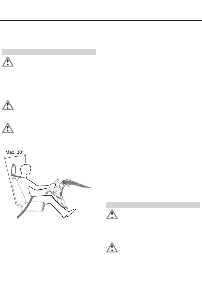
SITTING IN THE CORRECT
POSITION
WARNINGS
Sitting improperly, out of position or
with the seat back reclined too far
can take weight off the seat cushion
and affect the decision of the passenger
sensing system, resulting in serious injury
or death in the event of a crash. Always sit
upright against your seat back, with your
feet on the floor.
Do not recline the seat back as this
can cause the occupant to slide
under the safety belt, resulting in
serious injury in the event of a crash.
Do not place objects higher than the
seat back to reduce the risk of
serious injury in the event of a crash
or during heavy braking.
E68595
When you use them properly, the seat,
head restraint, safety belt and air bags will
provide optimum protection in the event
of a crash.
We recommend that you follow these
guidelines:
• Sit in an upright position with the base
of your spine as far back as possible.
• Do not recline the seat back more than
30 degrees.
• Adjust the head restraint so that the
top of it is level with the top of your
head and as far forward as possible.
Make sure that you remain
comfortable.
• Keep sufficient distance between
yourself and the steering wheel. We
recommend a minimum of 10 inches
(25 centimeters) between your
breastbone and the air bag cover.
• Hold the steering wheel with your arms
slightly bent.
• Bend your legs slightly so that you can
press the pedals fully.
• Position the shoulder strap of the
safety belt over the center of your
shoulder and position the lap strap
tightly across your hips.
Make sure that your driving position is
comfortable and that you can maintain full
control of your vehicle.
HEAD RESTRAINTS
WARNINGS
Fully adjust the head restraint before
you sit in or operate your vehicle. This
will help minimize the risk of neck
injury in the event of a collision. Do not
adjust the head restraint when your vehicle
is moving.
The head restraint is a safety device.
Whenever possible it should be
installed and properly adjusted when
the seat is occupied.
117
Seats
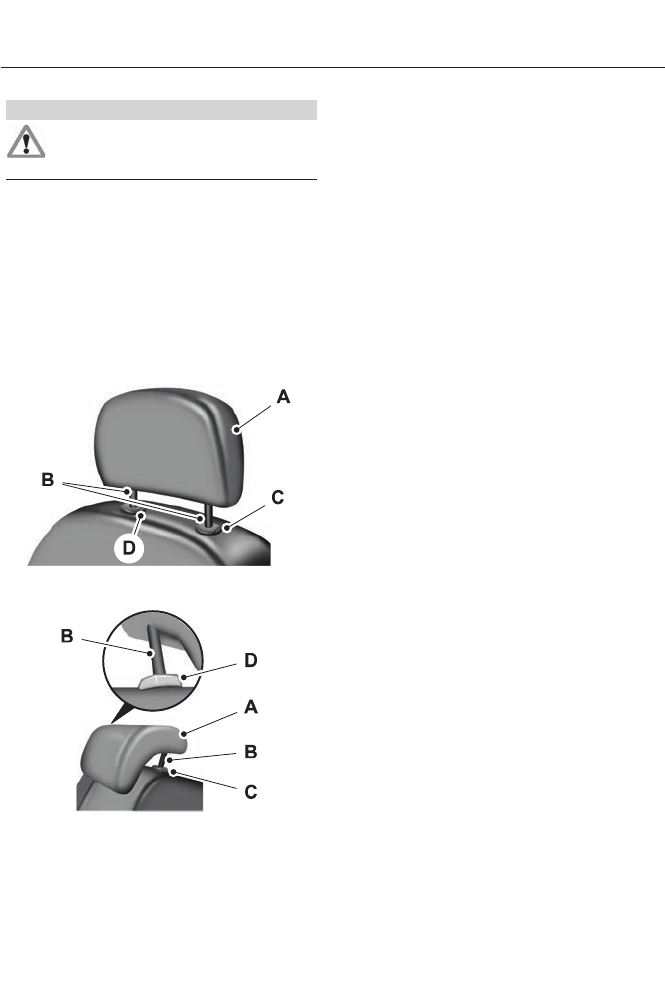
WARNINGS
Install the head restraint properly to
help minimize the risk of neck injury
in the event of a collision.
Note: Adjust the seat back to an upright
driving position before adjusting the head
restraint. Adjust the head restraint so that
the top of it is level with the top of your head
and as far forward as possible. Make sure
that you remain comfortable. If you are
extremely tall, adjust the head restraint to
its highest position.
Front seat and rear seat outboard head
restraints
E138642
Rear center head restraint
E138645
The head restraints consist of:
An energy absorbing head
restraint
A
Two steel stemsB
Guide sleeve adjust and unlock
button
C
Guide sleeve unlock and remove
button
D
Adjusting the Head Restraint
Raising the Head Restraint
Pull the head restraint up.
Lowering the Head Restraint
1. Press and hold button C.
2. Push the head restraint down.
Removing the Head Restraint
1. Pull the head restraint up until it
reaches its highest position.
2. Press and hold buttons C and D.
3. Pull the head restraint up.
Installing the Head Restraint
Align the steel stems into the guide sleeves
and push the head restraint down until in
locks.
Tilting Head Restraints
The front head restraints have a tilting
feature for extra comfort. To tilt the head
restraint, do the following:
118
Seats
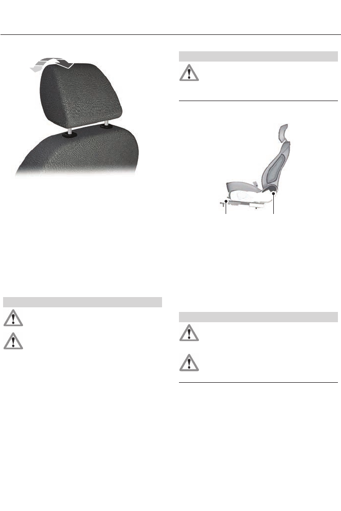
E144727
1. Adjust the seat back to an upright
driving or riding position.
2. Pivot the head restraint forward toward
your head to the desired position.
After the head restraint reaches the
forward-most tilt position, pivoting it
forward again will then release it to the
rearward, un-tilted position.
MANUAL SEATS
WARNINGS
Do not adjust the driver's seat or seat
back when your vehicle is moving.
Rock the seat backward and forward
after releasing the lever to make sure
that it is fully engaged.
WARNINGS
Reclining the seat back can cause an
occupant to slide under the seat's
safety belt, resulting in severe
personal injuries in the event of a crash.
The manual front seats consist of:
A B
E157060
a bar to move the seat backward
and forward
A
a lever to adjust the angle of the
seat back.
B
POWER SEATS (IF EQUIPPED)
WARNINGS
Do not adjust the driver's seat or
seatback when your vehicle is
moving.
Do not place cargo or any objects
behind the seatback before returning
it to the original position.
119
Seats
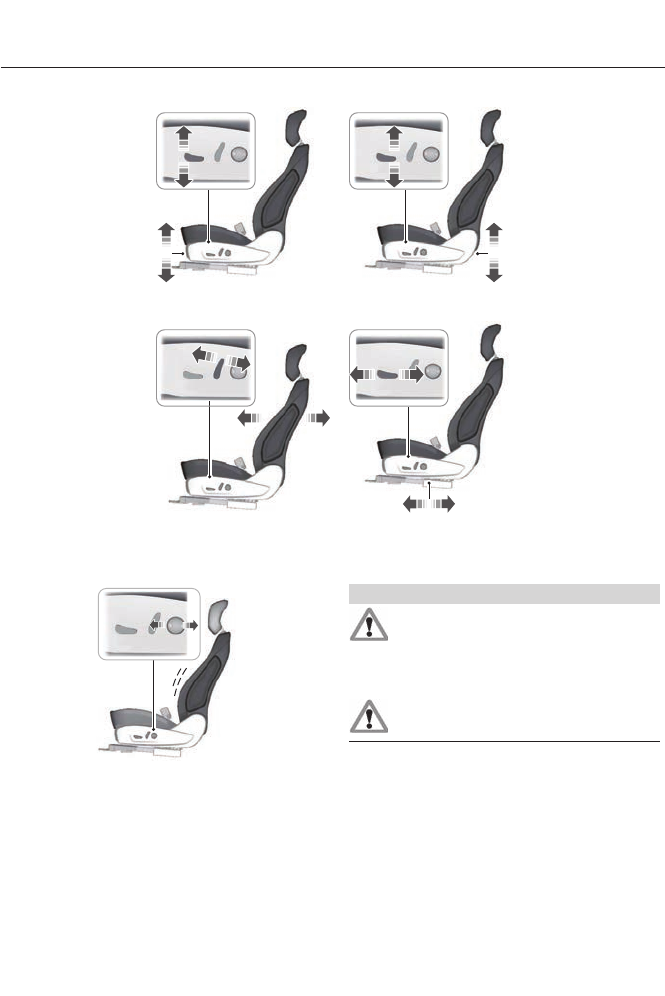
E144632
Power Lumbar (If Equipped)
E165608
MEMORY FUNCTION (IF EQUIPPED)
WARNINGS
Before activating the seat memory,
make sure that the area immediately
surrounding the seat is clear of
obstructions and that all occupants are
clear of moving parts.
Do not use the memory function
when your vehicle is moving.
This feature will automatically recall the
position of the driver's seat and power
mirrors. The memory control is located on
the driver’s door.
120
Seats

E142554
Saving a Pre-Set Position
1. Switch the ignition on.
2. Adjust the seat and exterior mirrors to
your desired position.
3. Press and hold the desired pre-set
button until you hear a single chime.
Up to three pre-set memory positions may
be saved. A memory pre-set may be saved
at any time.
Recalling a Pre-Set Position
Press and release the pre-set button
associated with your desired driving
position. The seat and mirrors will move to
the position stored for that pre-set.
Note: A pre-set memory position can only
be recalled when the ignition is off, or when
the transmission selector lever is in position
P or N (and your vehicle is not moving) if
the ignition is on.
A pre-set memory position can also be
recalled by pressing the unlock button on
your remote control or intelligent access
key if it is linked to a pre-set position, or by
a driver door handle unlock with an
intelligent access key present.
Linking a Pre-Set Position to your
Remote Control or Intelligent
Access Key
Your vehicle can save the pre-set memory
positions for up to three remote controls
or intelligent access (IA) keys.
1. With the ignition on, move the memory
positions to the desired positions.
2. Press and hold the desired pre-set
button for about five seconds. A chime
will sound after about two seconds.
Continue holding until a second chime
is heard.
3. Within three seconds, press the lock
button on the remote control you are
linking. A single chime will sound.
To unlink a remote control, follow the
same procedure – except in step 3, press
the unlock button on the remote control.
Note: To stop seat movement during a
recall, press any driver seat adjustment
control, any of the memory buttons, or any
mirror control switch.
Seat movement will also stop if you move
your vehicle.
Note: If more than one linked remote
control or IA key is in range, the memory
function will move to the settings of the first
key stored.
Easy Entry and Exit Function
If you enable the easy entry and exit
feature, it automatically moves the driver
seat position rearward up to five
centimeters when the transmission
selector lever is in position P and the key
is removed or the keyless start ignition is
turned off.
The driver seat will return to the previous
position when the key is put in the ignition
or the keyless start ignition is activated.
121
Seats
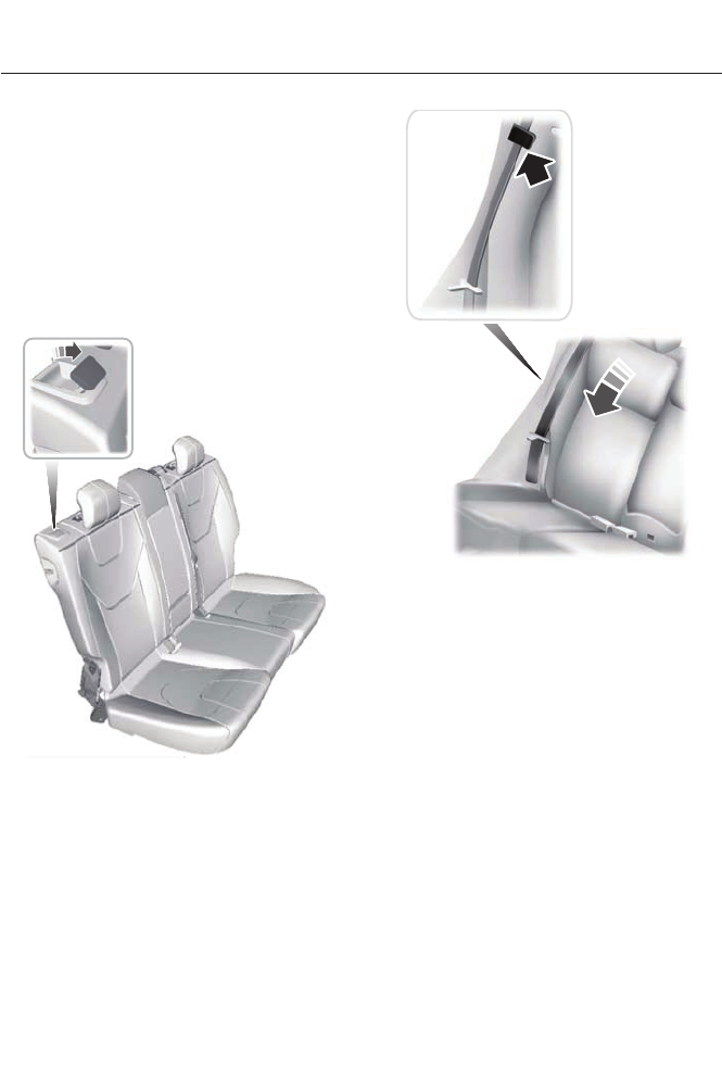
You can turn off the easy entry and exit
feature by using the driver information
display.
REAR SEATS
Note: Your vehicle may have split seat
backs that must be folded individually.
To lower the seat back(s) from inside the
vehicle, do the following:
E144634
1. Pull the handle to release the seat
back.
2. Push the seat back forward.
E164098
3. Stow the safety belt in the stowage
clip. This will prevent the safety belt
from getting caught in the seat latch.
When raising the seat back(s), make sure
you hear the seat latch into place.
122
Seats
HEATED SEATS (IF EQUIPPED)
WARNING
People who are unable to feel pain
to their skin because of advanced
age, chronic illness, diabetes, spinal
cord injury, medication, alcohol use,
exhaustion or other physical conditions,
must exercise care when using the heated
seat. The heated seat may cause burns
even at low temperatures, especially if
used for long periods of time. Do not place
anything on the seat that insulates against
heat, such as a blanket or cushion. This
may cause the heated seat to overheat.
Do not puncture the seat with pins, needles
or other pointed objects. This may damage
the heating element which may cause the
heated seat to overheat. An overheated
seat may cause serious personal injury.
Do not do the following:
• Place heavy objects on the seat.
• Operate the heated seat if water or any
other liquid is spilled on the seat. Allow
the seat to dry thoroughly.
• Operate the heated seats unless the
engine is running. Doing so can cause
the battery to lose charge.
E146941
Press the heated seat symbol to cycle
through the various heat settings and off.
Warmer settings are indicated by more
indicator lights.
VENTILATED SEATS (IF EQUIPPED)
The ventilated seats will only function
when the engine is running.
To operate the ventilated seats:
E146309
Press the ventilated seat symbol to cycle
through the various cooling settings and
off. Cooler settings are indicated by more
indicator lights.
If the engine falls below 350 RPM while
the ventilated seats are on, the feature will
turn itself off and will need to be
reactivated.
Heated and ventilated seat air
filter replacement (if equipped)
The climate controlled seat system
includes air filters. You must replace them
periodically.
The filters are located under each front
seat. You can access them from the
second row foot-well area. Move the front
seats all the way forward and to the full
up positions to ease access.
123
Seats
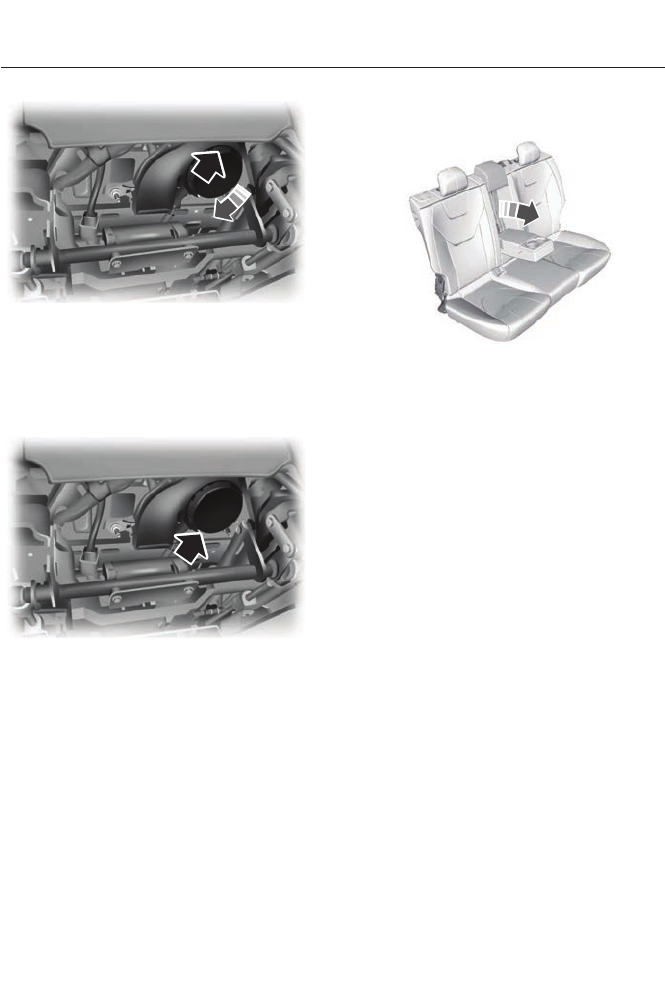
E146319
To remove an air filter:
1. Turn the vehicle off.
2. Push up on the outside rigid edge of
the filter and rotate counterclockwise
once the tabs are released, then
remove the filter.
E146321
To install a filter:
1. First, position the filter in its housing
making sure that the far forward end
is all the way up in the housing.
2. Push in on the center of the outside
edge of the filter and rotate clockwise
into the housing until it clips into
position.
REAR SEAT ARMREST
E144635
Fold the armrest down to use the armrest
and cupholder.
124
Seats
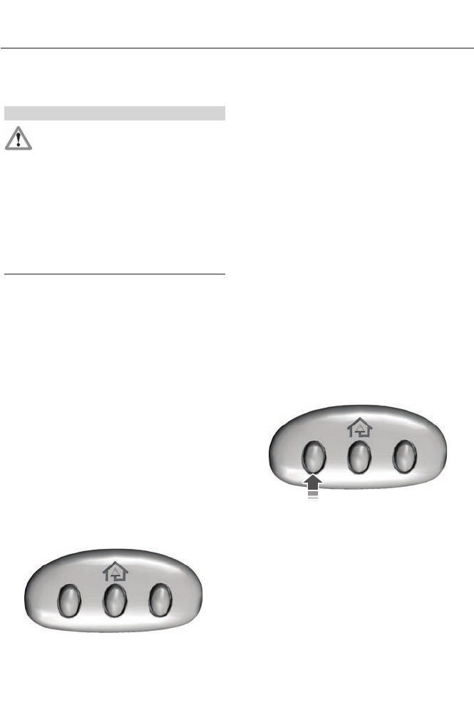
HomeLink Wireless Control
System (If Equipped)
WARNING
Do not use the system with any
garage door opener that does not
have the safety stop and reverse
feature as required by U.S. Federal Safety
Standards (this includes any garage door
opener manufactured before April 1, 1982).
A garage door opener which cannot detect
an object, signaling the door to stop and
reverse, does not meet current federal
safety standards. Using a garage door
opener without these features increases
the risk of serious injury or death.
Note: Make sure that the garage door and
security device are free from obstruction
when you are programming. Do not program
the system with the vehicle in the garage.
Note: Make sure you keep the original
remote control transmitter for use in other
vehicles as well as for future system
programming.
Note: We recommend that upon the sale
or lease termination of your vehicle, you
erase the programmed function buttons for
security reasons. See Erasing the function
button codes later in this section.
Note: You can program a maximum of
three devices. To change or replace any of
the three devices after it has been initially
programmed, you must first erase the
current settings. See Erasing the function
button codes later in this section.
E142657
The universal garage door opener replaces
the common hand-held garage door
opener with a three-button transmitter
that is integrated into the driver’s sun visor.
The system includes two primary features,
a garage door opener and a platform for
remote activation of devices within the
home. As well as being programmed for
garage doors, the system transmitter can
be programmed to operate entry gate
operators, security systems, entry door
locks and home or office lighting.
Additional system information can be
found online at www.homelink.com or by
calling the toll-free help line on
1-800-355-3515.
In-vehicle programming
This process is to program your hand-held
transmitter and your in-vehicle HomeLink
button.
Note: Put a new battery in the hand-held
transmitter. This will ensure quicker training
and accurate transmission of the
radio-frequency signal.
E142658
1. With your vehicle parked outside of the
garage, turn your ignition to the on
position, but do not start your vehicle.
2. Hold your hand-held garage door
transmitter 1–3 inches (2–8
centimeters) away from the HomeLink
button you want to program.
125
Universal Garage Door Opener
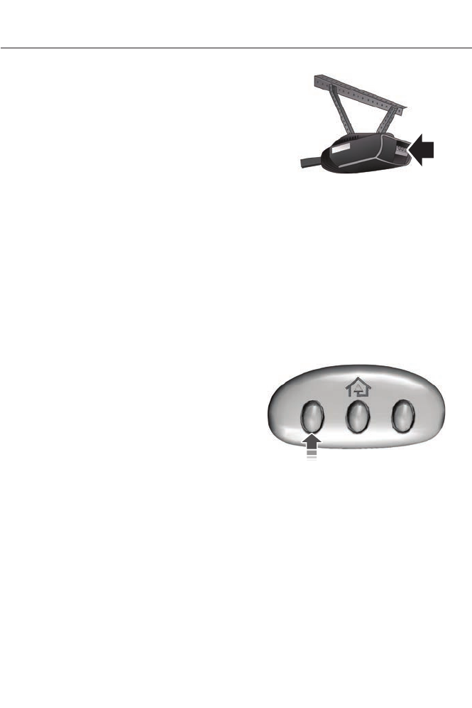
3. Using both hands, simultaneously,
press and hold the desired HomeLink
button and the hand-held transmitter
button. DO NOT release either one until
the HomeLink indicator light flashes
slowly and then rapidly. When the
indicator light flashes rapidly, both
buttons may be released. The rapid
flashing indicates successful training.
4. Press and hold the HomeLink button
you programmed for five seconds, then
release. You may need to do this twice
to activate the door. If your garage door
does not operate, watch the HomeLink
indicator light.
If the indicator light stays on, the
programming is complete. See
Programming your garage door motor
later in this section.
If the indicator light flashes rapidly for 2
seconds and then turns to a constant light,
the HomeLink button is not programmed
yet. Do the following:
Press and hold the HomeLink button while
you press and release the hand-held
transmitter button every 2 seconds. The
HomeLink indicator light will flash slowly
and then rapidly once the HomeLink
function button recognizes and accepts
the hand-held transmitter’s radio
frequency signal.
After programming the HomeLink button,
begin programming your garage door
opener motor.
Note: You may need a ladder to reach the
unit and you may need to remove the cover
or lamp lens on your garage door opener.
E142659
To program additional buttons, repeat
Steps 1 – 4.
For questions or comments, please contact
HomeLink at www.homelink.com or
1-800-355-3515.
Programming your garage door opener
motor
1. Press the learn button on the garage
door opener motor and then you have
30 seconds to complete the next two
steps.
2. Return to your vehicle.
E142658
3. Press and hold the function button you
want to program for 2 seconds, then
release. Repeat this step. Depending
on your brand of garage door opener,
you may need to repeat this sequence
a third time.
Erasing the Function Button Codes
Note: You cannot erase individual buttons.
126
Universal Garage Door Opener
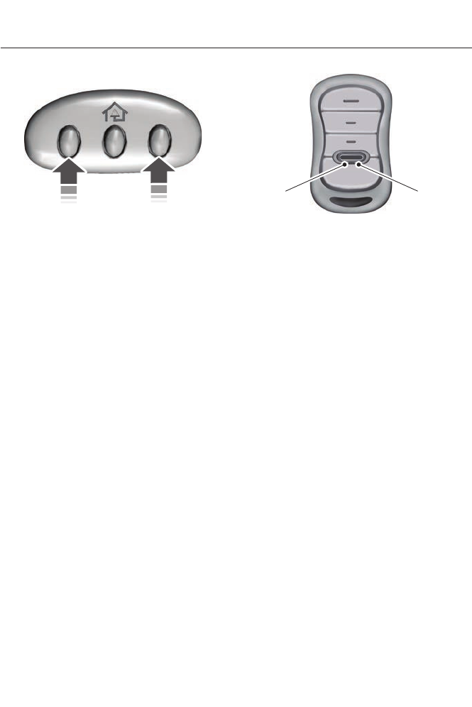
E142660
1. Press and hold the outer two function
buttons simultaneously for
approximately 20 seconds until the
indicator lights above the buttons flash
rapidly.
2. When the indicator lights flash, release
the buttons. The codes for all buttons
are erased.
Reprogramming a Single Button
To program a device to a previously trained
button, follow these steps:
1. Press and hold the desired button. Do
NOT release the button.
2. The indicator light will begin to flash
after 20 seconds. Without releasing the
button, follow Step 1 in the
Programming section.
For questions or comments, contact
HomeLink at www.homelink.com or
1-800-355-3515.
Programming to a Genie Intellicode 2
Garage Door Opener
Note: The Genie Intellicode 2 transmitter
must already be programmed to operate
with the garage door opener.
Note: To program HomeLink to the
transmitter you must first put the
transmitter into programming mode.
BA
E142661
Red indicator lightA.
Green indicator lightB.
1. Press and hold one of the buttons on
the hand-held transmitter for 10
seconds. The indicator light will change
from green to red and green.
2. Press the same button twice to confirm
the change to programming mode. If
done properly the indicator light will
appear red.
3. Hold the transmitter within 1–3 inches
(2–8 centimeters) of the button on the
visor you want to program.
4. Press and hold both the programmed
Genie button on the hand-held
transmitter and the button you want
to program. The indicator light on the
visor will flash rapidly when the
programming is successful.
Note: The Genie transmitter will transmit
for up to 30 seconds. If HomeLink does not
program within 30 seconds the Genie
transmitter will need to be pressed again. If
the Genie transmitter indicator light displays
green and red, release the button until the
indicator light turns off before pressing the
button again.
Once HomeLink has been programmed
successfully, the Genie transmitter must
be changed out of program mode. To do
this:
127
Universal Garage Door Opener
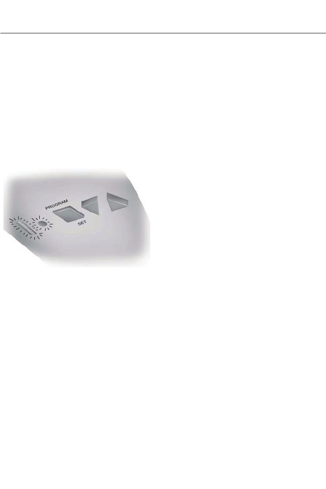
1. Press and hold the previously
programmed Genie button on the
hand-held transmitter for 10 seconds.
The indicator light will change from red
to red and green.
2. Press the same button twice to confirm
the change. If done correctly the
indicator light will turn green.
Programming HomeLink to the Genie
Intellicode Garage Door Opener Motor
Note: You may need a ladder to access the
garage door opener motor.
E142662
1. Press and hold the program button on
the garage door opener motor until
both blue indicator lights turn on.
2. Release the program button. Only the
smaller round indicator light should be
on.
3. Press and release the program button.
The larger purple indicator light will
flash.
Note: The next two steps must be
completed in 30 seconds.
4. Press and release the Genie Intellicode
2 hand-held transmitter’s previously
programmed button. Both indicator
lights on the garage door opener motor
unit should now flash purple.
5. Press and hold the previously
programmed button on the visor for 2
seconds. Repeat this step up to 3 times
until the garage door moves.
Programming is now complete.
Clearing a HomeLink Device
To erase programming from the three
HomeLink buttons press and hold the two
outer HomeLink buttons until the indicator
light begins to flash. The indicator light will
begin flashing in 10 to 20 seconds, at which
time both buttons should be released.
Programming has now been erased, and
the indicator light should blink slowly to
indicate the device is in train mode when
any of the three HomeLink buttons are
pressed.
FCC and RSS-210 Industry Canada
Compliance
This device complies with Part 15 of the
FCC Rules and with RSS-210 of Industry
Canada. Operation is subject to the
following two conditions: (1) this device
may not cause harmful interference, and
(2) this device must accept any
interference received, including
interference that may cause undesired
operation.
Changes or modifications to your device
not expressly approved by the party
responsible for compliance can void the
user’s authority to operate the equipment.
128
Universal Garage Door Opener
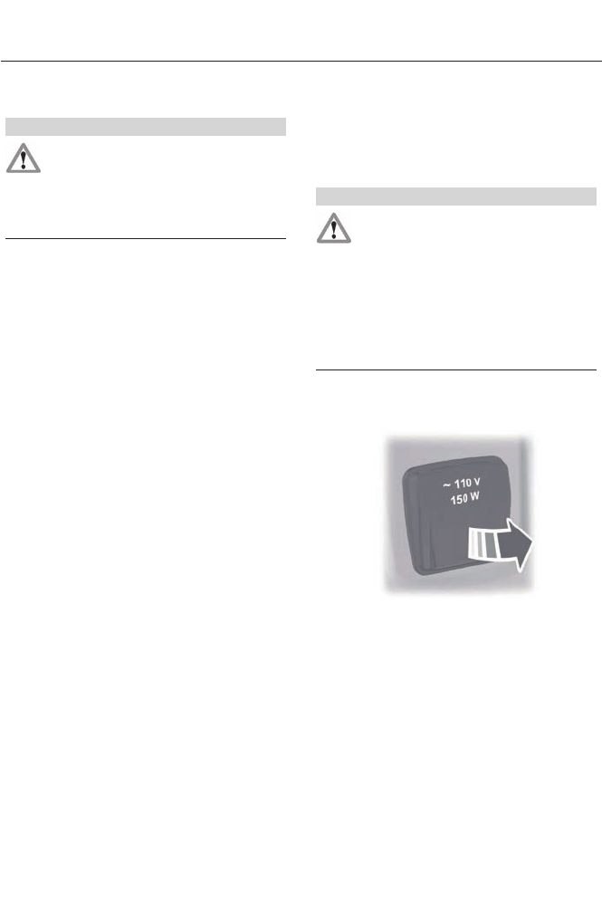
12 Volt DC Power Point
WARNING
Do not plug optional electrical
accessories into the cigar lighter
socket (if equipped). Improper use
of the lighter can cause damage not
covered by your warranty, and can result
in fire or serious injury.
Note: If used when the vehicle is not
running, the battery will discharge. There
may be insufficient power to restart your
vehicle.
Note: Do not insert objects other than an
accessory plug into the power point. This
will damage the outlet and blow the fuse.
Note: Do not hang any type of accessory or
accessory bracket from the plug.
Note: Do not use the power point over the
vehicle capacity of 12 volt DC 180 watts or
a fuse may blow.
Note: Do not use the power point for
operating a cigar lighter element.
Note: Improper use of the power point can
cause damage not covered by your
warranty.
Note: Always keep the power point caps
closed when not in use.
Run the vehicle for full capacity use of the
power point. To prevent the battery from
being discharged:
• Do not use the power point longer than
necessary when the vehicle is not
running.
• Do not leave devices plugged in
overnight or when the vehicle is parked
for extended periods.
Locations
Power points may be found:
• in the front of the center console
• inside the center console storage bin
• on the rear of the center console.
110 Volt AC Power Point (If Equipped)
WARNING
Do not keep electrical devices
plugged in the power point whenever
the device is not in use. Do not use
any extension cord with the 110 volt AC
power point, since it will defeat the safety
protection design. Doing so my cause the
power point to overload due to powering
multiple devices that can reach beyond
the 150 watt load limit and could result in
fire or serious injury.
Note: Keep the vehicle running to use the
power point.
E143941
The power point is used for powering
electrical devices that require up to 150
watts. It is located on the rear of the center
console.
When the indicator light, located on the
power point, is:
• on — power point is ready to supply
power.
• off — power point power supply is off;
ignition is not on.
• flashing — power point is in fault mode.
129
Auxiliary Power Points

The power point temporarily turns off
power if the 150 watt limit is exceeded. It
can also switch to a fault mode when it is
overloaded, overheated, or shorted. Unplug
your device and switch the ignition off then
on for overloading and shorting conditions.
Let the system cool off, then turn the
ignition off then on for an overheating
condition.
The power point is not designed for electric
devices such as:
• Cathode ray tube type televisions
• Motor loads, for example vacuum
cleaners, electric saws and other
electric power tools, or
compressor-driven refrigerators
• Measuring devices which process
precise data, for example medical
equipment or measuring equipment
• Other appliances requiring an
extremely stable power supply, for
example microcomputer-controlled
electric blankets or touch sensor lamps
130
Auxiliary Power Points
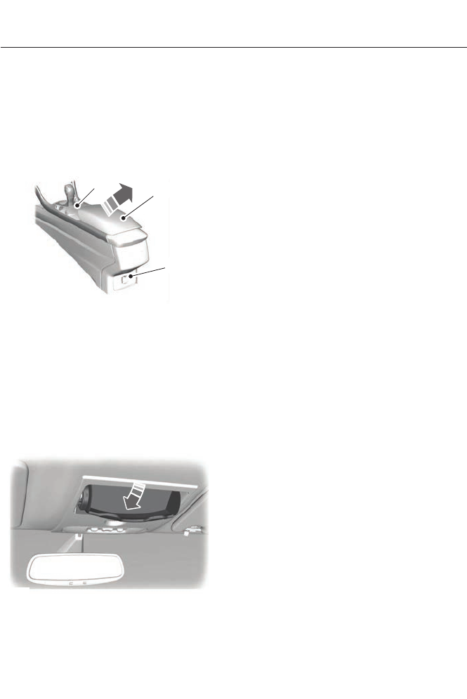
CENTER CONSOLE
Stow items in the cupholder carefully as
items may become loose during hard
braking, acceleration or collisions, including
hot drinks which may spill.
Available console features include:
AB
C
E143942
CupholderA
Storage compartment with
auxiliary power point, auxiliary
input jack, USB port and media
hub
B
Auxiliary power pointC
OVERHEAD CONSOLE
E75193
Press near the rear edge of the door to
open it.
131
Storage Compartments
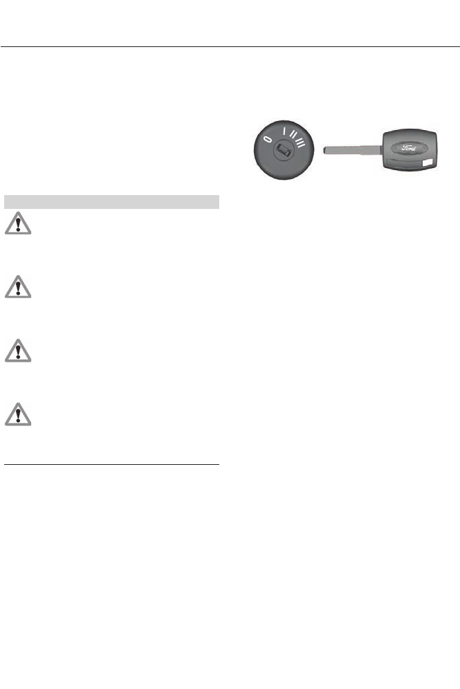
GENERAL INFORMATION
If you disconnect the battery, your vehicle
may exhibit some unusual driving
characteristics for approximately 5 miles
(8 kilometers) after you reconnect it. This
is because the engine management system
must realign itself with the engine. You can
disregard any unusual driving
characteristics during this period.
WARNINGS
Extended idling at high engine
speeds can produce very high
temperatures in the engine and
exhaust system, creating the risk of fire or
other damage.
Do not park, idle or drive your vehicle
on dry grass or other dry ground
cover. The emission system heats up
the engine compartment and exhaust
system, creating the risk of fire.
Do not start the engine in a closed
garage or in other enclosed areas.
Exhaust fumes can be toxic. Always
open the garage door before you start the
engine.
If you smell exhaust fumes inside
your vehicle, have your vehicle
checked by your authorized dealer
immediately. Do not drive your vehicle if
you smell exhaust fumes.
The powertrain control system meets all
Canadian interference-causing equipment
standard requirements regulating the
impulse electrical field or radio noise.
When you start the engine, avoid pressing
the accelerator pedal before and during
operation. Only use the accelerator pedal
when you have difficulty starting the
engine.
IGNITION SWITCH
E72128
0 (off) - The ignition is off.
Note: When you switch the ignition off and
leave your vehicle, do not leave your key in
the ignition. This could cause your vehicle
battery to lose charge.
I (accessory) - Allows the electrical
accessories, such as the radio, to operate
while the engine is not running.
Note: Do not leave the ignition key in this
position for too long. This could cause your
vehicle battery to lose charge.
II (on) - All electrical circuits are
operational and the warning lamps and
indicators illuminate.
III (start) - cranks the engine.
KEYLESS STARTING
Note: The keyless starting system may not
function if the key is close to metal objects
or electronic devices such as cellular
phones.
Note: A valid key must be located inside
your vehicle to switch the ignition on and
start the engine.
132
Starting and Stopping the Engine

Ignition Modes
E144447
The keyless starting system has three
modes:
•Off: Turns the ignition off.
• Without applying the brake pedal,
press and release the button once
when the ignition is in the on mode,
or when the engine is running but
the vehicle is not moving.
•On: All electrical circuits are
operational and the warning lamps and
indicators illuminate.
• Without applying the brake pedal,
press and release the button once.
•Start: Starts the engine.
• Press the brake pedal, and then
press the button for any length of
time. An indicator light on the
button illuminates when then
ignition is on and when the engine
starts.
STARTING A GASOLINE
ENGINE
When the engine starts for the first time
on your drive, the idle speed increases, this
helps to warm up the engine. If the engine
idle speed does not slow down
automatically, have your vehicle checked
by an authorized dealer.
Note: You can crank the engine for a total
of 60 seconds (without the engine starting)
before the starting system temporarily
disables. The 60 seconds does not have to
be all at once. For example, if you crank the
engine three times for 20 seconds each
time, without the engine starting, you
reached the 60-second time limit. A
message appears in the information display
alerting you that you exceeded the cranking
time. You cannot attempt to start the engine
for at least 15 minutes. After 15 minutes, you
are limited to a 15-second engine cranking
time. You need to wait 60 minutes before
you can crank the engine for 60 seconds
again.
Before starting the vehicle, check the
following:
• Make sure all occupants have fastened
their safety belts.
• Make sure the headlamps and
electrical accessories are off.
• Make sure the parking brake is on.
• Move the transmission selector lever
to position P.
• Turn the ignition key to position II. If
your vehicle is equipped with a keyless
ignition, see the following instructions.
Vehicles with an Ignition Key
Note: Do not touch the accelerator pedal.
1. Fully press the brake pedal.
2. Turn the key to position III to start the
vehicle. Release the key when the
vehicle starts.
Note: The engine may continue cranking
for up to 15 seconds or until it starts.
Note: If you cannot start the engine on the
first try, wait for a short period and try again.
Vehicles with Keyless Start
Note: Do not touch the accelerator pedal.
1. Fully press the brake pedal.
133
Starting and Stopping the Engine
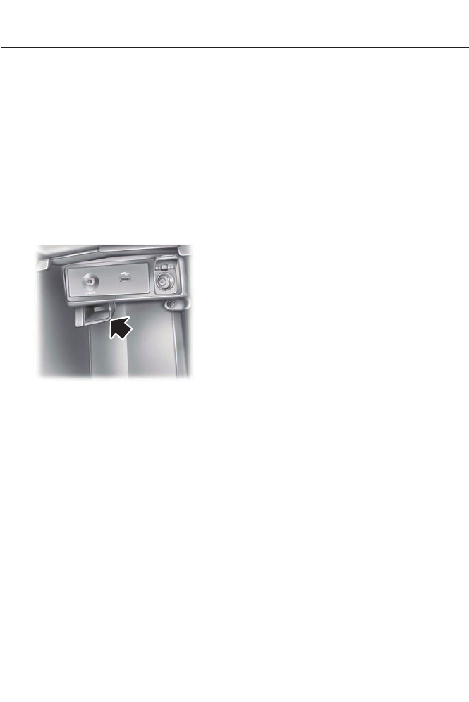
2. Press the button.
Note: The green ready indicator illuminates
letting you know that the vehicle is ready
for driving. Since your vehicle is equipped
with a silent key start, the engine may not
start at the time of the vehicle start. See
Hybrid Electric Vehicle (page 138).
The system does not function if:
• The key frequencies are jammed.
• The key battery has no charge.
If you are unable to start the vehicle, do
the following:
E147165
1. Locate the key backup slot in center
console utility compartment.
2. With the buttons facing the rear of the
vehicle and the key ring up, place the
key into backup slot.
3. With the key in this position, press the
brake pedal, and then the button to
switch on the vehicle.
Fast Restart
The fast restart feature allows you to
restart the engine within 20 seconds of
switching it off, even if a valid key is not
present.
Within 20 seconds of switching the engine
off, press the brake pedal and press the
button. After 20 seconds have expired, you
can no longer restart the vehicle without
the key present inside your vehicle.
Once the vehicle has started, it remains
running until you press the button, even if
the system does not detect a valid key. If
you open and close a door while the vehicle
is running, the system searches for a valid
key. You cannot restart the engine if the
system does not detect a valid key within
20 seconds.
Automatic Shutdown
This feature automatically shuts down the
vehicle if it has been idling for an extended
period. The ignition also turns off in order
to save battery power. Before the vehicle
shuts down, a message appears in the
information display showing a timer
counting down from 30 seconds. If you do
not intervene within 30 seconds, the
vehicle shuts down. Another message
appears in the information display to
inform you that the vehicle has shut down
in order to save fuel. Start your vehicle as
you normally do.
Automatic Shutdown Override
Note: You cannot permanently switch off
the automatic shutdown feature. When you
switch it off temporarily, it turns on at the
next ignition cycle.
You can stop the shutdown, or reset the
timer, at any point before the 30-second
countdown has expired by doing any of the
following:
134
Starting and Stopping the Engine

• You can reset the timer by interacting
with your vehicle (such as pressing the
brake pedal or accelerator pedal).
• You can temporarily switch off the
shutdown feature any time the ignition
is on (for the current ignition cycle
only). Use the information display to
do so. See Information Displays
(page 84).
• During the countdown before
shutdown, you are prompted to press
OK or RESET (depending on your type
of information display) to temporarily
switch the feature off (for the current
ignition cycle only).
Switching Off the Vehicle When It
Is Stationary
Vehicles with an Ignition Key
1. Move the transmission selector lever
to position P.
2. Turn the key to position 0.
3. Apply the parking brake.
Vehicles with Keyless Start
1. Move the transmission selector lever
to position P.
2. Press the button once.
3. Apply the parking brake.
Note: This switches off the ignition, all
electrical circuits, warning lamps and
indicators.
Note: If the engine is idling for 30 minutes,
the ignition and engine automatically shut
down.
Switching Off the Vehicle When It
Is Moving
WARNING
Switching off the engine when the
vehicle is still moving will result in a
loss of brake and steering assistance.
The steering will not lock, but higher effort
will be required. When the ignition is
switched off, some electrical circuits,
warning lamps and indicators may also be
off.
Vehicles with an Ignition Key
1. Move the transmission selector lever
to position N and use the brakes to
bring your vehicle to a safe stop.
2. When your vehicle has stopped, move
the transmission selector lever to
position P and turn the key to position
0.
3. Apply the parking brake.
Vehicles with Keyless Start
1. Move the transmission selector lever
to position N and use the brakes to
bring your vehicle to a safe stop.
2. When your vehicle has stopped, move
the transmission selector lever to
position P.
3. Press and hold the button for one
second, or press it three times within
two seconds.
4. Apply the parking brake.
135
Starting and Stopping the Engine
Guarding Against Exhaust Fumes
WARNING
If you smell exhaust fumes inside
your vehicle, have your vehicle
checked by your authorized dealer
immediately. Do not drive your vehicle if
you smell exhaust fumes. Carbon
monoxide is present in exhaust fumes.
Take precautions to avoid its dangerous
effects.
Important Ventilating Information
If you stop your vehicle and the leave the
engine idling for long periods, we
recommend that you do one of the
following:
• Open the windows at least 1 inch (2.5
centimeters)
• Set your climate control to outside air.
ENGINE BLOCK HEATER (IF
EQUIPPED)
WARNINGS
Failure to follow engine block heater
instructions could result in property
damage or serious personal injury.
Do not use your heater with
ungrounded electrical systems or
two-pronged adapters. There is a risk
of electrical shock.
Note: The heater is most effective when
outdoor temperatures are below 0°F
(-18°C).
The heater acts as a starting aid by
warming the engine coolant. This allows
the climate control system to respond
quickly. The equipment includes a heater
element (installed in the engine block) and
a wire harness. You can connect the
system to a grounded 120-volt AC
electrical source.
We recommend that you do the following
for a safe and correct operation:
• Use a 16-gauge outdoor extension cord
that is product certified by
Underwriter’s Laboratory (UL) or
Canadian Standards Association
(CSA). This extension cord must be
suitable for use outdoors, in cold
temperatures, and be clearly marked
Suitable for Use with Outdoor
Appliances. Do not use an indoor
extension cord outdoors. This could
result in an electric shock or become a
fire hazard.
• Use as short an extension cord as
possible.
• Do not use multiple extension cords.
• Make sure that when in operation, the
extension cord plug and heater cord
plug connections are free and clear of
water. This could cause an electric
shock or fire.
• Make sure your vehicle is parked in a
clean area, clear of combustibles.
• Make sure the heater, heater cord and
extension cord are firmly connected.
• Check for heat anywhere in the
electrical hookup once the system has
been operating for approximately 30
minutes.
• Make sure the heater system is
checked for proper operation before
winter.
136
Starting and Stopping the Engine

Using the Engine Block Heater
The engine block heater plug is located in
a housing in the left fog lamp bezel. Open
the hinged, circular door and make sure
the receptacle terminals are clean and dry
prior to use. Clean them with a dry cloth if
necessary.
The heater uses 0.4 to 1.0 kilowatt-hours
of energy per hour of use. The system does
not have a thermostat. It will achieve
maximum temperature after
approximately three hours of operation. If
you use the heater longer than three hours,
this will not improve system performance
and will use unnecessary electricity.
137
Starting and Stopping the Engine
HYBRID ELECTRIC VEHICLE
Plug-in Power Mode and Hybrid
Mode (Fusion Energi Only)
You must plug in your Fusion Energi vehicle
regularly for optimal use of the high
voltage battery's extended range
capability. When you charge your vehicle,
you add electrical energy that is then used
to propel the vehicle in plug-in power
mode. Your estimated electric range in this
mode is shown in an enhanced battery
gauge on the instrument panel display.
Electric only operation is maximized in
plug-in power mode. System conditions
may require engine operation; however,
plug-in power will be used whenever
possible.
When your plug-in power has been
depleted, the powertrain system will
automatically switch to hybrid mode. Your
battery gauge will show an electric range
of zero before transitioning to a simple
battery graphic upon entering hybrid mode.
Hybrid mode uses both the gasoline engine
and electric motor to power your vehicle
and maximize fuel economy as with Fusion
Hybrid.
EV Modes (Fusion Energi Only)
E144814
Your vehicle contains selectable
EV modes through the EV button
on the center console.
These modes are available when the
vehicle can run under high voltage battery
power. With the vehicle in driving mode,
you can change EV modes with each press
of the EV button. The current mode
displays in the left hand instrument cluster
screen.
Auto EV
E155152
This mode provides an
automatic use of high voltage
battery power during the drive,
staying in electric mode when possible and
running the engine when needed. This
mode will be the only one available if the
plug-in power has been depleted.
EV Now
E144814
This mode provides an electric
only driving experience using
plug-in power. The left-hand
information display will change to an
Energy Use screen that supplies EV specific
tools and functions. The vehicle may
accelerate more slowly and the top speed
may be lower than in Auto mode. At any
time, the engine may be enabled by using
one of the following methods:
1. Press the OK button on the left 5–way
steering wheel control while viewing
the EV screen. The vehicle will enable
the engine as needed, and will
automatically return to EV Now after
eight seconds or when the engine is no
longer needed.
2. Press the accelerator pedal fully. A pop
up message stating Press OK to
Enable Engine will appear. Press OK
on the left steering wheel button to
activate as needed. The message will
disappear if the accelerator pedal is
released.
3. Press the EV button. This will change
the mode to EV Later and permit
engine operation.
The vehicle may automatically enter
Engine Enabled mode if system conditions
require it. A message Engine Enabled for
System Performance will display if this
occurs. This is normal function, and your
vehicle will return to EV Now when
possible.
138
Unique Driving Characteristics

The vehicle may enter Enable Engine mode
if the climate control is in a defrost mode
and the outside temperature is cold. A
message Engine Enabled Due to Defrost
will display if this occurs. If defrost is not
needed, select a different climate control
mode to permit EV Now.
There is a blue EV icon that is displayed in
the left-hand information display when EV
Now is enabled. If the vehicle is in the
Engine Enabled mode, the EV icon will be
yellow.
EV Now will automatically exit when the
Plug in power has been depleted.
EV Later
E151263
This mode saves most of the
high voltage battery plug in
power for future use (for
example, your initial drive is at high speeds
on open roads, but later your drive will be
at low speeds in an urban area where
plug-in power usage is most efficient).
Your vehicle will run the engine as needed
and keep most of the high voltage battery
plug in power for later use in Auto Mode or
EV Now mode.
There is a white EV Later icon that appears
on the left-hand information display when
EV Later is enabled.
The EV Later mode will automatically reset
to EV Auto mode when the vehicle is
powered off. You may press the EV button
twice during the next drive to return to EV
Later mode, if desired.
Hybrid Vehicle Operation (Fusion
Hybrid and Fusion Energi)
This hybrid vehicle combines electric and
gasoline propulsion to provide
breakthrough performance and improved
efficiency. Familiarizing yourself with these
unique characteristics will provide an
optimal driving experience from your new
vehicle.
Note: You may notice higher engine speeds
upon start-up. This temporary condition is
normal and necessary to heat up the cabin
and minimize emissions.
E144692
Starting: When you start your
vehicle, a green ready indicator
light will appear in the lower right
portion of the instrument cluster and a
ready to drive message will appear in the
middle of the left cluster screen, letting
you know that the vehicle is ready for
driving.
The engine may not start because this
vehicle is equipped with silent key start.
This fuel saving feature allows your vehicle
to be ready–to–drive without requiring the
gas engine to be running. This indicator will
remain on while the vehicle is on, whether
the engine is running or not to indicate the
vehicle is capable of movement (using its
electric motor, engine, or both). Typically,
the engine will not start unless the vehicle
is cold, a climate control change is
requested, or the accelerator is pressed.
Driving: The gas engine automatically
starts and stops to provide power when
needed and to save fuel when not needed.
While coasting at low speeds, coming to
a stop, or standing, the gas engine normally
shuts down and the vehicle operates in
electric-only mode. Conditions that may
cause the engine to start up or remain
running include:
• considerable vehicle acceleration
• vehicle speed above 60 mph (96
km/h) For Fusion Energi vehicles, you
can drive up to 85 mph [137 km/h] in
EV mode.
• ascending a hill
• charge level of high voltage battery is
low
139
Unique Driving Characteristics

• very high or low outside temperature
(to provide system cooling or heating)
For Fusion Energi vehicles, climate
control demands by passengers may
not directly cause the engine to run.
This only occurs when the high voltage
battery charge is low, or if the outside
temperature is cold enough to require
the engine to provide additional heat
for the cabin.
• engine not warm enough to provide
passenger requested cabin
temperature.
Stopping: The gas engine may shut off
to conserve fuel as you come to a stop.
Restarting the vehicle is not required.
Simply step on the accelerator when you
are ready to drive.
Transmission Operation: Due to the
technologically advanced,
electronically-controlled continuously
variable transaxle, you will not feel shift
changes like those of a non-hybrid vehicle.
Note: Since engine speed is controlled by
the transmission, it may seem elevated at
times. This is normal hybrid operation and
helps deliver fuel efficiency and
performance.
Neutral: It is not recommended to idle the
vehicle in position N for extended periods
of time because this will discharge your
high voltage battery and decrease fuel
economy. The engine will not start or stop,
and cannot provide power to the hybrid
system in position N.
Low Gear: Low gear (position L) is
designed to mimic the enhanced engine
braking available in non-hybrid vehicles.
Low gear will produce high engine speeds
to provide necessary engine braking. This
is normal and will not damage your vehicle.
In low gear, the gas engine will remain on
more often than in position D.
Reverse: In position R, vehicle speed is
limited to 22 mph (35 km/h).
Unique Hybrid Operating
Characteristics
Your vehicle behaves differently compared
to a non-hybrid. Here is a description of the
major differences:
Battery: Your hybrid is equipped with a
high voltage battery. A cool battery ensures
battery life and provides the best possible
performance. Your hybrid high voltage
battery may periodically re-condition itself
to ensure maximum efficiency. You may
notice slight changes in driveability during
this process, but it is an important part of
your hybrid's high voltage battery
optimization features.
The high voltage battery is cooled by cabin
air pulled into the high voltage battery
through vents in the rear package tray.
Avoid placing objects on the package tray
which could block air flow through the
vents.
Engine: The engine speed in your hybrid
is not directly tied to your vehicle speed.
Your vehicle's engine and transmission are
designed to deliver the power you need at
the most efficient engine speed. During
heavy accelerations, your hybrid may reach
high engine speeds (up to 6000 rpm).
In prolonged mountainous driving, you may
see the engine tachometer changing
without your input. This is intentional and
maintains the battery charge level. You
may also notice during extended downhill
driving that your engine continues to run
instead of shutting off.
During this engine braking, the engine stays
on, but it is not using any fuel. You may also
hear a slight whine or whistle when
operating your vehicle. This is the normal
operation of the electric generator in the
hybrid system.
140
Unique Driving Characteristics

During certain events (such as vehicle
servicing) your low voltage 12-volt battery
may become disconnected or disabled.
Once the battery is reconnected and after
driving the vehicle, the engine may
continue to operate for three to five
seconds after the key is turned to off. This
is a normal condition.
Braking: Your hybrid is equipped with
standard hydraulic braking and
regenerative braking. Regenerative braking
is performed by your transmission and it
captures brake energy and stores it in your
high voltage battery.
Driving to optimize fuel economy
Note: Having your engine running is not
always an indication of inefficiency. In some
cases, it is actually more efficient than
driving in electric mode.
Your fuel economy should improve
throughout your hybrid's break-in period.
As with any vehicle, fuel economy can be
significantly impacted by your driving
habits and accessory usage. For best
results, keep in mind these tips:
• Keep the tires properly inflated and
only use the recommended size.
• Aggressive driving increases the
amount of energy required to move
your vehicle. In general, better fuel
economy is achieved with mild to
moderate acceleration and
deceleration. Moderate braking is
particularly important since it allows
you to maximize the energy captured
by the regenerative braking system.
Additional Tips:
• Do not carry extra loads.
• Be mindful of adding external
accessories that may increase
aerodynamic drag.
• Observe posted speed limits.
• Perform all scheduled maintenance.
• There is no need to wait for your engine
to warm up. The vehicle is ready to
drive immediately after starting.
EV+ Mode
Your vehicle will recognize your frequent
destinations and allow for more EV driving
as you approach them. For example, when
nearing your home it should be easier to
stay in electric mode. The EV indicator will
display EV+ when this mode is active. You
should see this approximately 1/8 mile
(200 meters) from a frequent destination.
See Information Displays (page 84).
Note: Frequent destinations are learned by
your vehicle after two to four weeks of use.
These destinations can be cleared with a
Lifetime Summary reset through the
Settings menu.
Note: The EV+ feature can be turned on or
off through the Driver Assist section of the
Settings menu.
141
Unique Driving Characteristics

Frequently asked questions
AnswerQuestion
The high voltage battery is electrically isol-
ated from the rest of the vehicle when the
key is off. When the key is turned to on, high
voltage contactors inside the battery are
closed to make the electricity available to
the motor/generator and enable the vehicle
to drive. The clicks are the sound of these
contactors as they close and open during
start up and shut down.
What are the series of clicks from the cargo
area when I first turn the key in the ignition?
The vehicle's computer will determine if an
engine start is required at key-on. Silent key
start will start the engine if it is necessary
for cabin heating, windshield defrost, or if
the outside temperature is low. (For Fusion
Energi vehicles, the engine may not be
required to operate these functions.)
Why does the engine sometimes start at
key-on?
There are several reasons the engine stays
on for an extended amount of time when
it is first started. One common reason is to
ensure that the emissions components are
warm enough to minimize tailpipe emis-
sions. As the climate gets cooler, this
engine-on time is extended.
Why does it take a long time before the
engine shuts down?
The engine is required to turn on above this
speed to protect the transmission hard-
ware. (For Fusion Energi vehicles, you can
travel up to 85 mph [137 km/h] in EV mode.
Why does my engine never shut down
above 60 mph (96 km/h)
In order to ensure that the climate control
system can begin heating the cabin or
defrosting the windshield as soon as a
driver requests it, the engine coolant
temperature has to be kept sufficiently hot.
Keeping the engine on is required to main-
tain the correct coolant temperature.
Why does my engine stay on when it is
extremely cold outside?
142
Unique Driving Characteristics

AnswerQuestion
Your vehicle's engine and transmission are
designed to deliver the power you need at
the most efficient engine speed. This may
be higher than expected during heavy
accelerations, and may fluctuate during
steady state driving. These are character-
istics of the Atkinson engine cycle and the
transmission technology that help
maximize your hybrid's fuel economy.
Why does my engine rev up so high some-
times when I accelerate?
The fan noise comes from a fan located
outside the high voltage battery. This fan
turns on when the battery requires cooling
air. The fan speed, and associated noise
level, will change according to the amount
of cooling required to maintain good
performance. Maintaining the battery
temperature at optimal conditions also
prolongs the useful life of the battery and
helps to achieve better fuel economy.
What is the fan noise I hear from the rear
of my hybrid?
The engine oil should be changed every
10000 miles (16000 km) or once per year
under normal operating conditions.
What is the engine oil change service
interval?
Your hybrid vehicle can use E15 (15%
ethanol, 85% gasoline) fuel, but you may
notice slightly reduced fuel economy
because ethanol contains less energy per
gallon than gasoline. Your hybrid vehicle is
not designed to use E85 (85% ethanol).
Can I put E15 or E85 in my vehicle, and how
will it affect my fuel economy?
The high voltage battery system is designed
to last the life of the vehicle and requires
no maintenance.
How long will my high voltage battery last?
Does it need maintenance?
There are no provisions for charging the
high voltage battery from a power supply
external to the vehicle. (For Fusion Energi
vehicles, the vehicle can be plugged into a
110 volt outlet with charge cord provided.)
Can you charge the battery with a plug into
an A/C outlet?
Yes. Your hybrid vehicle can be flat towed
without modification. See Towing (page
207).
Can I tow the hybrid behind my motor home
with all four wheels down?
143
Unique Driving Characteristics
SAFETY PRECAUTIONS
WARNINGS
Do not overfill the fuel tank. The
pressure in an overfilled tank may
cause leakage and lead to fuel spray
and fire.
The fuel system may be under
pressure. If you hear a hissing sound
near the fuel filler door (Easy Fuel
capless fuel system), do not refuel until
the sound stops. Otherwise, fuel may spray
out, which could cause serious personal
injury.
Automotive fuels can cause serious
injury or death if misused or
mishandled.
The flow of fuel through a fuel pump
nozzle can produce static electricity,
which can cause a fire if fuel is
pumped into an ungrounded fuel container.
Fuel ethanol and gasoline may
contain benzene, which is a
cancer-causing agent.
When refueling always shut the
engine off and never allow sparks or
open flames near the filler neck.
Never smoke or use a cell phone while
refueling. Fuel vapor is extremely
hazardous under certain conditions. Avoid
inhaling excess fumes.
Observe the following guidelines when
handling automotive fuel:
• Extinguish all smoking materials and
any open flames before refueling your
vehicle.
• Always turn off the vehicle before
refueling.
• Automotive fuels can be harmful or
fatal if swallowed. Fuel such as
gasoline is highly toxic and if
swallowed can cause death or
permanent injury. If fuel is swallowed,
call a physician immediately, even if no
symptoms are immediately apparent.
The toxic effects of fuel may not be
visible for hours.
• Avoid inhaling fuel vapors. Inhaling too
much fuel vapor of any kind can lead
to eye and respiratory tract irritation.
In severe cases, excessive or prolonged
breathing of fuel vapor can cause
serious illness and permanent injury.
• Avoid getting fuel liquid in your eyes. If
fuel is splashed in the eyes, remove
contact lenses (if worn), flush with
water for 15 minutes and seek medical
attention. Failure to seek proper
medical attention could lead to
permanent injury.
• Fuels can also be harmful if absorbed
through the skin. If fuel is splashed on
the skin, clothing or both, promptly
remove contaminated clothing and
wash skin thoroughly with soap and
water. Repeated or prolonged skin
contact with fuel liquid or vapor causes
skin irritation.
• Be particularly careful if you are taking
“Antabuse” or other forms of disulfiram
for the treatment of alcoholism.
Breathing gasoline vapors, or skin
contact could cause an adverse
reaction. In sensitive individuals, serious
personal injury or sickness may result.
If fuel is splashed on the skin, promptly
wash skin thoroughly with soap and
water. Consult a physician immediately
if you experience an adverse reaction.
144
Fuel and Refueling

FUEL QUALITY
Note: Use of any fuel other than those
recommended may cause powertrain
damage, a loss of vehicle performance and
repairs may not be covered under warranty.
Choosing the Right Fuel
Use only UNLEADED fuel or UNLEADED
fuel blended with a maximum of 15%
ethanol. Do not use fuel ethanol (E85),
diesel fuel, fuel-methanol, leaded fuel or
any other fuel because it could damage or
impair the emission control system.
Your vehicle was not designed to use fuel
or fuel additives with metallic compounds,
including manganese-based additives. The
use of leaded fuel is prohibited by law.
Octane Recommendations
Regular unleaded gasoline with a pump
(R+M)/2 octane rating of 87 is
recommended. Some fuel stations offer
fuels posted as regular with an octane
rating below 87, particularly in high altitude
areas. Fuels with octane levels below 87
are not recommended.
Do not be concerned if your engine
sometimes knocks lightly. However, if it
knocks heavily while you are using fuel with
the recommended octane rating, see your
authorized dealer to prevent any engine
damage.
Fuel Freshness Mode (Energi
Vehicles Only)
This feature helps keeps the fuel system
functional and the fuel fresh.
If you operate your vehicle mainly in plug-in
power mode using electricity from plugging
in without refueling, the gasoline in your
tank eventually becomes old. Old fuel can
damage the engine and fuel system.
To prevent the fuel from becoming old,
your vehicle will automatically enter fuel
freshness mode. In fuel freshness mode
operates, your vehicle will operate in hybrid
mode causing the gasoline engine to run
in order to consume the fuel in the fuel
tank.
Note: If new fuel is not added during an 18
month period, fuel freshness mode will
consume fuel until about 1 gallon (3.8 liters)
is left in the tank.
During fuel freshness mode:
• The information display screen will
indicate that fuel freshness mode is
active.
• The vehicle will only run in hybrid mode.
EV Now will not be available.
• Most of the plug-in power will be
stored until fuel freshness mode is
completed.
Note: EV Now can resume if less than 1
gallon (3.8 liters) of fuel is left in the tank.
Note: In most cases, when the fuel level is
below 1/4 tank, refueling the vehicle will end
fuel freshness mode and EV Now will now
become available. Refueling after
consuming a full tank in fuel freshness mode
will end the mode.
Note: It is recommended to use a fuel
stabilizer if you consume less than a full
tank of fuel during an 18 month period.
REFUELING
WARNINGS
Fuel vapor burns violently and a fuel
fire can cause severe injuries.
Read and follow all the instructions
on the pump island.
Turn off your engine when you are
refueling.
145
Fuel and Refueling
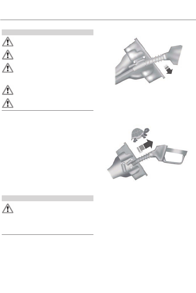
WARNINGS
Do not smoke if you are near fuel or
refueling your vehicle.
Keep sparks, flames and smoking
materials away from fuel.
Stay outside your vehicle and do not
leave the fuel pump unattended
when refueling your vehicle. This is
against the law in some places.
Keep children away from the fuel
pump; never let children pump fuel.
Do not use personal electronic
devices while refueling.
Use the following guidelines to avoid
electrostatic charge build-up when filling
an ungrounded fuel container:
• Place approved fuel container on the
ground.
• Do not fill a fuel container while it is in
the vehicle (including the cargo area).
• Keep the fuel pump nozzle in contact
with the fuel container while filling.
• Do not use a device that would hold
the fuel pump handle in the fill position.
Easy Fuel™ Capless Fuel System
(Non-Energi Vehicles)
WARNING
The fuel system may be under
pressure. If you hear a hissing sound
near the fuel filler door, do not refuel
until the sound stops. Otherwise, fuel may
spray out, which could cause serious
personal injury.
When fueling your vehicle:
1. Put the vehicle in P (Park) and turn the
ignition off.
2. Open the fuel filler door.
E156032
3. Slowly insert the fuel filler nozzle fully
into the fuel system, and leave the
nozzle fully inserted to open both doors
until you are done pumping. Hold the
handle higher during insertion for easier
access.
E154765
4. After you are done pumping fuel, slowly
remove the fuel filler nozzle. Allow
approximately five to ten seconds after
pumping fuel before removing the fuel
filler nozzle. This allows residual fuel
to drain back into the fuel tank and not
spill onto the vehicle.
Note: A fuel spillage concern may occur if
overfilling the fuel tank. Do not overfill the
tank to the point that the fuel is able to
bypass the fuel filler nozzle. The overfilled
fuel may run down the drain located below
and in front of the fuel filler door.
146
Fuel and Refueling
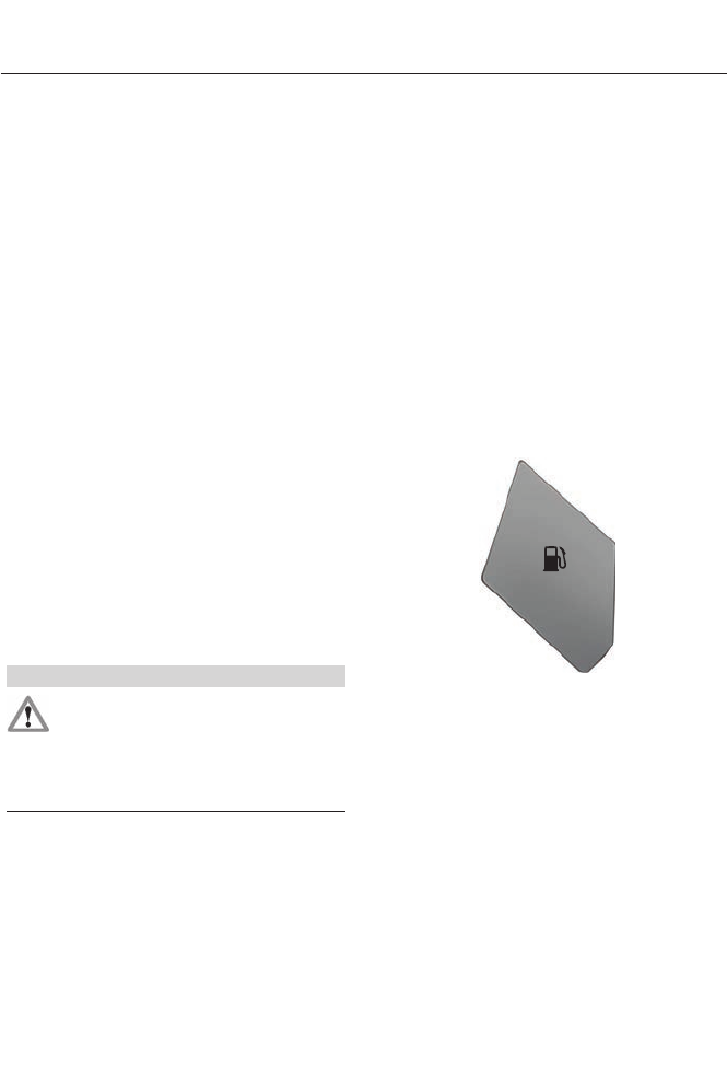
If the fuel fill inlet was not properly closed,
a Check Fuel Fill Inlet message may
appear on the instrument cluster.
At the next opportunity, do the following:
1. Safely pull off the road.
2. Put the vehicle in P (Park) and turn the
ignition off.
3. Open the fuel filler door and remove
any visible debris from the fuel fill
opening.
4. Insert either the fuel fill nozzle or the
fuel fill funnel provided with the vehicle
several times to dislodge any debris
and allow the inlet to close properly.
If this action corrects the problem, the
message may not reset immediately. It
may take several driving cycles for the
message to turn off. A driving cycle
consists of an engine start-up (after four
or more hours with the engine off) followed
by city or highway driving. Continuing to
drive with the message on may cause the
service engine soon lamp to turn on as
well.
Easy Fuel™ Capless System
(Energi Vehicles Only)
WARNING
The fuel system may be under
pressure. If you hear a hissing sound
near the fuel filler door, do not refuel
until the sound stops. Otherwise, fuel may
spray out, which could cause serious
personal injury.
Note: Your vehicle features a locking fuel
door and an auto-sealing feature that locks
the fuel tank refueling valve. Before you can
refuel your vehicle you must first press the
button located on the center console.
Pressing this button will unlock the fuel tank
refueling valve allowing the fuel filler door
to open so that the fuel filler nozzle can be
inserted into the fuel inlet. This could take
up to 15 seconds before the fuel filler door
pops open allowing the insertion of the fuel
filler nozzle.
When fueling your vehicle:
1. Put the vehicle in P (Park) and turn the
ignition off.
2. Press the fuel button located on the
center console.
E146221
3. Wait up to 15 seconds before opening
the fuel filler door. During this time a
Please Wait to Refuel message will
appear in the information display
screen.
4. When the door is open a Ready to
Refuel message will appear in the
information display screen indicating
that the vehicle is ready to be filled. The
vehicle will remain ready to refuel for
approximately 20 minutes. If more than
20 minutes is required, the refueling
button will need to be pressed again.
(You may experience the fuel pump
shutting off if the refuel button is not
pressed again).
147
Fuel and Refueling
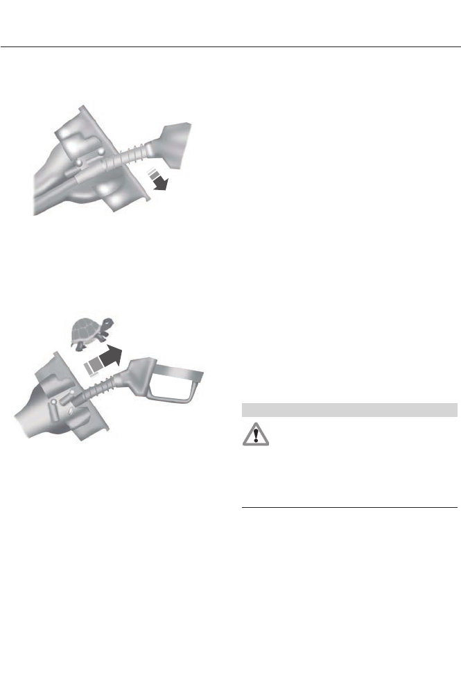
5. Open the fuel filler door.
E156032
6. Slowly insert the fuel filler nozzle fully
into the fuel system, and leave the
nozzle fully inserted to open both doors
until you are done pumping. Hold the
handle higher during insertion for easier
access.
E154765
7. After you are done pumping fuel, slowly
remove the fuel filler nozzle. Allow
approximately five to ten seconds after
pumping fuel before removing the fuel
filler nozzle. This allows residual fuel
to drain back into the fuel tank and not
spill onto the vehicle.
Note: A fuel spillage concern may occur if
overfilling the fuel tank. Do not overfill the
tank to the point that the fuel is able to
bypass the fuel filler nozzle. The overfilled
fuel may run down the drain located below
and in front of the fuel filler door.
If the fuel fill inlet was not properly closed,
a Check Fuel Fill Inlet message may
appear on the instrument cluster. At the
next opportunity, do the following:
1. Safely pull off the road.
2. Put the vehicle in P (Park) and turn the
ignition off.
3. Open the fuel filler door and remove
any visible debris from the fuel fill
opening.
4. Insert either the fuel fill nozzle or the
fuel fill funnel provided with the vehicle
several times to dislodge any debris
and allow the inlet to close properly.
If this action corrects the problem, the
message may not reset immediately. It
may take several driving cycles for the
message to turn off. A driving cycle
consists of an engine start-up (after four
or more hours with the engine off) followed
by city or highway driving. Continuing to
drive with the message on may cause the
service engine soon lamp to turn on as
well.
Using the manual override lever
WARNING
The fuel system may be under
pressure. Insert the fuel nozzle
slowly. If you hear a hissing sound
near the fuel filler door, do not refuel until
the sound stops. Otherwise, fuel may spray
out, which could cause serious personal
injury.
Note: The vehicle must be in P (Park) when
using the manual override feature.
The manual override lever is located inside
of the trunk on the left rear side panel.
When using the fuel door manual override
to access the fuel fill inlet:
1. Turn the ignition on prior using a
manual override.
148
Fuel and Refueling
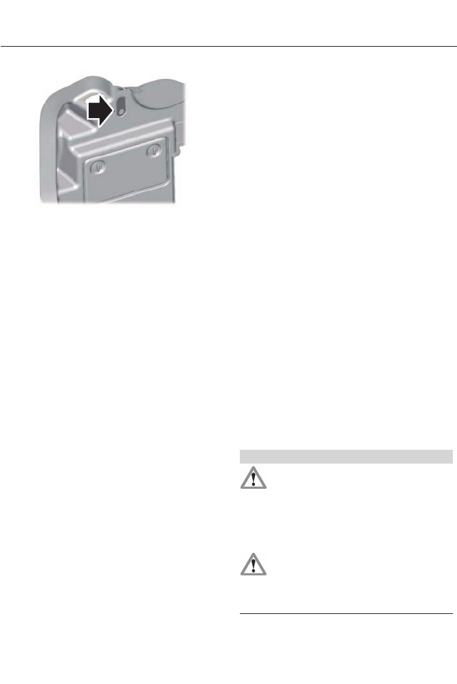
E156033
2. Pull the manual override mechanism
located in trunk.
3. Key off and complete refueling within
20 minutes. If more than 20 minutes is
required, close fuel door, and repeat
procedure.
This will enable you to refuel without any
issue.
Note: A fuel spillage concern may occur if
overfilling the fuel tank. Do not overfill the
tank to the point that the fuel is able to
bypass the fuel filler nozzle. The overfilled
fuel may run down the drain located below
and in front of the fuel filler door.
If the fuel fill inlet was not properly closed,
a Check Fuel Fill Inlet message may
appear on the instrument cluster. At the
next opportunity, do the following:
1. Safely pull off the road.
2. Put the vehicle in P (Park) and turn the
ignition off.
3. Open the fuel filler door and remove
any visible debris from the fuel fill
opening.
4. Insert either the fuel fill nozzle or the
fuel fill funnel provided with the vehicle
several times to allow the inlet to close
properly. This will dislodge any debris
preventing the inlet from sealing.
If this action corrects the problem, the
message may not reset immediately. It
may take several driving cycles for the
message to turn off. A driving cycle
consists of an engine start-up (after four
or more hours with the engine off) followed
by city/highway driving. Continuing to drive
with the message on may cause the service
engine soon lamp to turn on as well.
RUNNING OUT OF FUEL
Avoid running out of fuel because this
situation may have an adverse effect on
vehicle components.
If you have run out of fuel:
• To start the vehicle with a keyless
ignition, just start the engine. Crank
time will be longer than usual.
• Normally, adding 1 gallon (3.8 liters) of
fuel is enough to restart the vehicle. If
the vehicle is out of fuel and on a steep
grade, more than 1 gallon (3.8 liters)
may be required.
• The service engine soon indicator may
come on.
Refilling With a Portable Fuel
Container (Except Energi
Vehicles)
WARNINGS
Do not insert the nozzle of portable
fuel containers or aftermarket
funnels into the capless fuel system.
This could damage the fuel system and its
seal, and may cause fuel to run onto the
ground instead of filling the tank, which
could result in serious personal injury.
Do not try to pry open or push open
the capless fuel system with foreign
objects. This could damage the fuel
system and its seal and cause injury to you
or others.
149
Fuel and Refueling
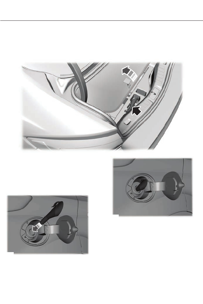
Note: Do not use aftermarket funnels; they
will not work with the capless fuel system
and can damage it. The included funnel has
been specially designed to work safely with
your vehicle.
When filling the vehicle’s fuel tank from a
portable fuel container, use the funnel
included with the vehicle.
E163066
The funnel is located in the rear of the
vehicle, inside the load compartment,
underneath the load floor carpet and is
accessible from the trunk.
1. Locate the portable funnel that comes
with your vehicle.
E157279
2. Slowly insert the funnel into the
capless fuel system.
E157280
3. Fill the vehicle with fuel from the
portable fuel container.
4. When done, clean the funnel or
properly dispose of it. Extra funnels can
be purchased from your authorized
dealer if you choose to dispose of the
funnel.
150
Fuel and Refueling
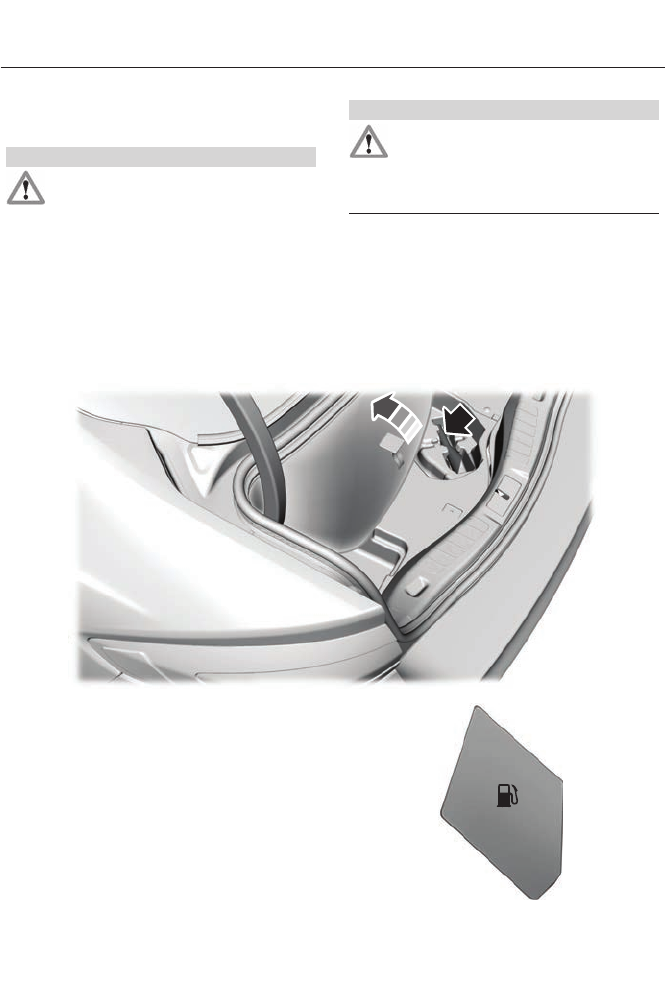
Refilling With a Portable Fuel
Container (Energi Vehicles Only)
WARNINGS
Do not insert the nozzle of portable
fuel containers or aftermarket
funnels into the capless fuel system.
This could damage the fuel system and its
seal, and may cause fuel to run onto the
ground instead of filling the tank, which
could result in serious personal injury.
WARNINGS
Do not try to pry open or push open
the capless fuel system with foreign
objects. This could damage the fuel
system and its seal and cause injury to you
or others.
Note: Do not use aftermarket funnels; they
will not work with the capless fuel system
and can damage it. The included funnel has
been specially designed to work safely with
your vehicle.
When filling the vehicle’s fuel tank from a
portable fuel container, use the funnel
included with the vehicle.
E163067
The funnel is located in the rear of the
vehicle, inside the load compartment,
underneath the load floor carpet and is
accessible from the trunk (remove
120–volt convenience cord for access).
1. Locate the portable funnel that comes
with your vehicle.
E146221
151
Fuel and Refueling
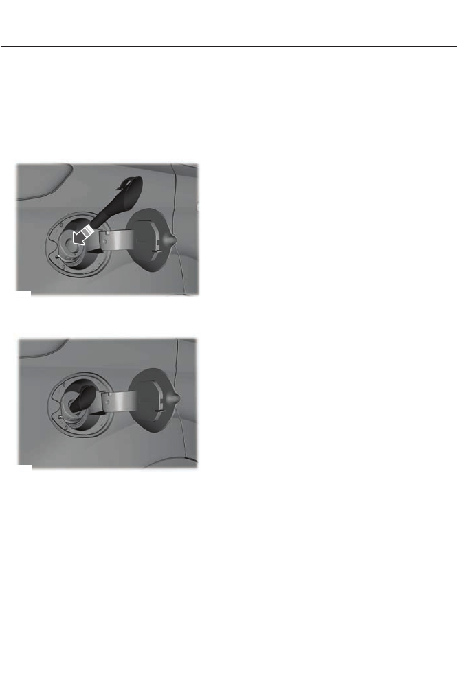
2. Press the fuel button located on the
center console. Wait up to 15 seconds
for the fuel door to open. AReady to
Fuel message will appear in the
information display screen.
3. Locate the portable funnel that comes
with your vehicle.
E157279
4. Slowly insert the funnel into the
capless fuel system.
E157280
5. Fill the vehicle with fuel from the
portable fuel container.
6. Close the fuel door.
Note: If the fuel door is not closed and the
vehicle is driven, the check engine light in
the instrument cluster may come on.
7. When done, clean the funnel or
properly dispose of it. Extra funnels can
be purchased from your authorized
dealer if you choose to dispose of the
funnel.
FUEL CONSUMPTION
Note: The amount of usable fuel in the
empty reserve varies and should not be
relied upon to increase driving range. When
refueling your vehicle after the fuel gauge
indicates empty, you might not be able to
refuel the full amount of the advertised
capacity of the fuel tank due to the empty
reserve still present in the tank.
Empty reserve is the amount of fuel
remaining in the tank after the fuel gauge
indicates empty. Do not rely on this fuel for
driving. The usable capacity of the fuel
tank is the amount of fuel that can be put
into the tank after the gauge indicates
empty. The advertised capacity is the total
fuel tank size – it is the combined usable
capacity plus the empty reserve.
Filling the Tank
For consistent results when filling the fuel
tank:
• Turn the ignition off before fueling; an
inaccurate reading results if the engine
is left running.
• Use the same fill rate
(low-medium-high) each time the tank
is filled.
• Allow no more than two automatic
click-offs when filling.
Results are most accurate when the filling
method is consistent.
Calculating Fuel Economy
Do not measure fuel economy during the
first 1000 miles (1600 kilometers) of
driving (this is your engine’s break-in
period); a more accurate measurement is
obtained after 2000 miles - 3000 miles
(3200 kilometers - 4800 kilometers). Also,
fuel expense, frequency of fill ups or fuel
gauge readings are not accurate ways to
measure fuel economy.
152
Fuel and Refueling
1. Fill the fuel tank completely and record
the initial odometer reading.
2. Each time you fill the tank, record the
amount of fuel added.
3. After at least three to five tank fill ups,
fill the fuel tank and record the current
odometer reading.
4. Subtract your initial odometer reading
from the current odometer reading.
5. Calculate fuel economy by dividing
miles traveled by gallons used (For
Metric: Multiply liters used by 100, then
divide by kilometers traveled).
Keep a record for at least one month and
record the type of driving (city or highway).
This provides an accurate estimate of the
vehicle’s fuel economy under current
driving conditions. Additionally, keeping
records during summer and winter show
how temperature impacts fuel economy.
In general, lower temperatures mean lower
fuel economy.
EMISSION CONTROL SYSTEM
WARNINGS
Do not park, idle, or drive your vehicle
in dry grass or other dry ground cover.
The emission system heats up the
engine compartment and exhaust system,
which can start a fire.
Exhaust leaks may result in entry of
harmful and potentially lethal fumes
into the passenger compartment. If
you smell exhaust fumes inside your
vehicle, have your dealer inspect your
vehicle immediately. Do not drive if you
smell exhaust fumes.
Your vehicle is equipped with various
emission control components and a
catalytic converter which will enable your
vehicle to comply with applicable exhaust
emission standards. To make sure that the
catalytic converter and other emission
control components continue to work
properly:
To make sure that the catalytic converter
and other emission control components
continue to work properly:
• Use only the specified fuel listed.
• Avoid running out of fuel.
• Do not turn off the ignition while your
vehicle is moving, especially at high
speeds.
• Have the items listed in scheduled
maintenance information performed
according to the specified schedule.
The scheduled maintenance items listed
in scheduled maintenance information are
essential to the life and performance of
your vehicle and to its emissions system
If other than Ford, Motorcraft® or
Ford-authorized parts are used for
maintenance replacements or for service
of components affecting emission control,
such non-Ford parts should be equivalent
to genuine Ford Motor Company parts in
performance and durability.
Illumination of the service engine soon
indicator, charging system warning light or
the temperature warning light, fluid leaks,
strange odors, smoke or loss of engine
power could indicate that the emission
control system is not working properly.
An improperly operating or damaged
exhaust system may allow exhaust to
enter the vehicle. Have a damaged or
improperly operating exhaust system
inspected and repaired immediately.
153
Fuel and Refueling
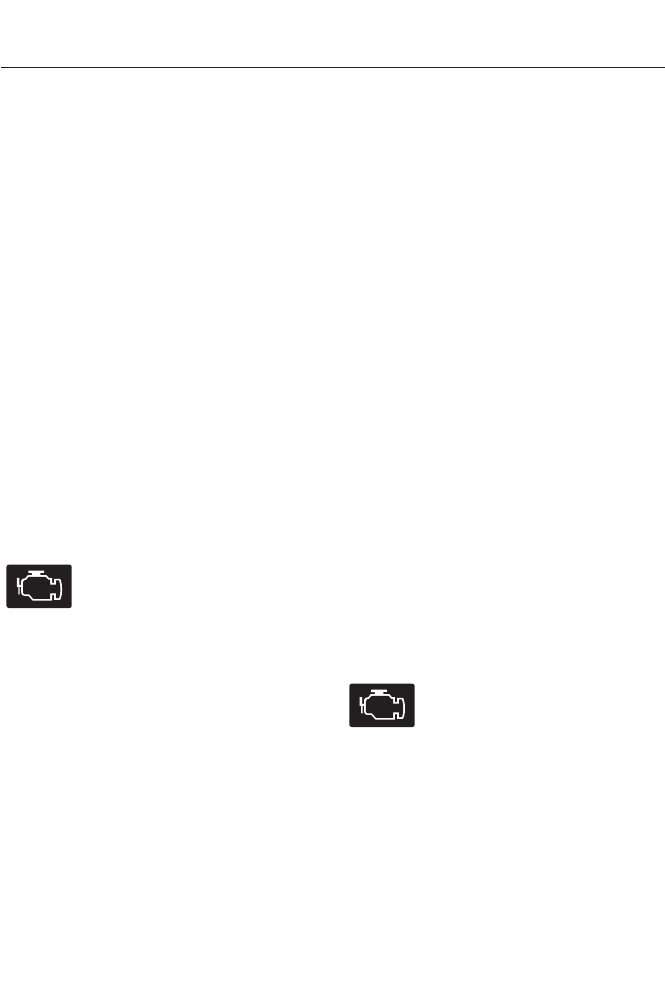
Do not make any unauthorized changes to
your vehicle or engine. By law, vehicle
owners and anyone who manufactures,
repairs, services, sells, leases, trades
vehicles, or supervises a fleet of vehicles
are not permitted to intentionally remove
an emission control device or prevent it
from working. Information about your
vehicle’s emission system is on the Vehicle
Emission Control Information Decal
located on or near the engine. This decal
also lists engine displacement
Please consult your warranty information
for complete details.
On-Board Diagnostics (OBD-II)
Your vehicle is equipped with a computer
that monitors the engine’s emission control
system. This system is commonly known
as the on-board diagnostics system
(OBD-II). The OBD-II system protects the
environment by ensuring that your vehicle
continues to meet government emission
standards. The OBD-II system also assists
your authorized dealer in properly servicing
your vehicle.
When the service engine soon
indicator illuminates, the OBD-II
system has detected a
malfunction. Temporary malfunctions may
cause the service engine soon indicator to
illuminate. Examples are:
1. The vehicle has run out of fuel—the
engine may misfire or run poorly.
2. Poor fuel quality or water in the
fuel—the engine may misfire or run
poorly.
3. The fuel fill inlet may not have been
properly closed. See Refueling (page
145).
4. Driving through deep water—the
electrical system may be wet.
These temporary malfunctions can be
corrected by filling the fuel tank with good
quality fuel, properly closing the fuel fill
inlet or letting the electrical system dry out.
After three driving cycles without these or
any other temporary malfunctions present,
the service engine soon indicator should
stay off the next time the engine is started.
A driving cycle consists of a cold engine
startup followed by mixed city/highway
driving. No additional vehicle service is
required.
If the service engine soon indicator remains
on, have your vehicle serviced at the first
available opportunity. Although some
malfunctions detected by the OBD-II may
not have symptoms that are apparent,
continued driving with the service engine
soon indicator on can result in increased
emissions, lower fuel economy, reduced
engine and transmission smoothness, and
lead to more costly repairs.
Readiness for
Inspection/Maintenance (I/M)
Testing
Some state/provincial and local
governments may have
Inspection/Maintenance (I/M) programs
to inspect the emission control equipment
on your vehicle. Failure to pass this
inspection could prevent you from getting
a vehicle registration.
If the service engine soon
indicator is on or the bulb does
not work, the vehicle may need
to be serviced. See On-Board Diagnostics.
Your vehicle may not pass the I/M test if
the service engine soon indicator is on or
not working properly (bulb is burned out),
or if the OBD-II system has determined
that some of the emission control systems
have not been properly checked. In this
case, the vehicle is considered not ready
for I/M testing.
154
Fuel and Refueling

If the vehicle’s engine or transmission has
just been serviced, or the battery has
recently run down or been replaced, the
OBD-II system may indicate that the
vehicle is not ready for I/M testing. To
determine if the vehicle is ready for I/M
testing, turn the ignition key to the on
position for 15 seconds without cranking
the engine. If the service engine soon
indicator blinks eight times, it means that
the vehicle is not ready for I/M testing; if
the service engine soon indicator stays on
solid, it means that the vehicle is ready for
I/M testing.
The OBD-II system is designed to check
the emission control system during normal
driving. A complete check may take several
days. If the vehicle is not ready for I/M
testing, the following driving cycle
consisting of mixed city and highway
driving may be performed:
15 minutes of steady driving on an
expressway/highway followed by 20
minutes of stop-and-go driving with at
least four 30-second idle periods.
Allow the vehicle to sit for at least eight
hours with the ignition Off. Then, start the
vehicle and complete the above driving
cycle. The vehicle must warm up to its
normal operating temperature. Once
started, do not turn off the vehicle until the
above driving cycle is complete. If the
vehicle is still not ready for I/M testing, the
above driving cycle will have to be
repeated.
155
Fuel and Refueling
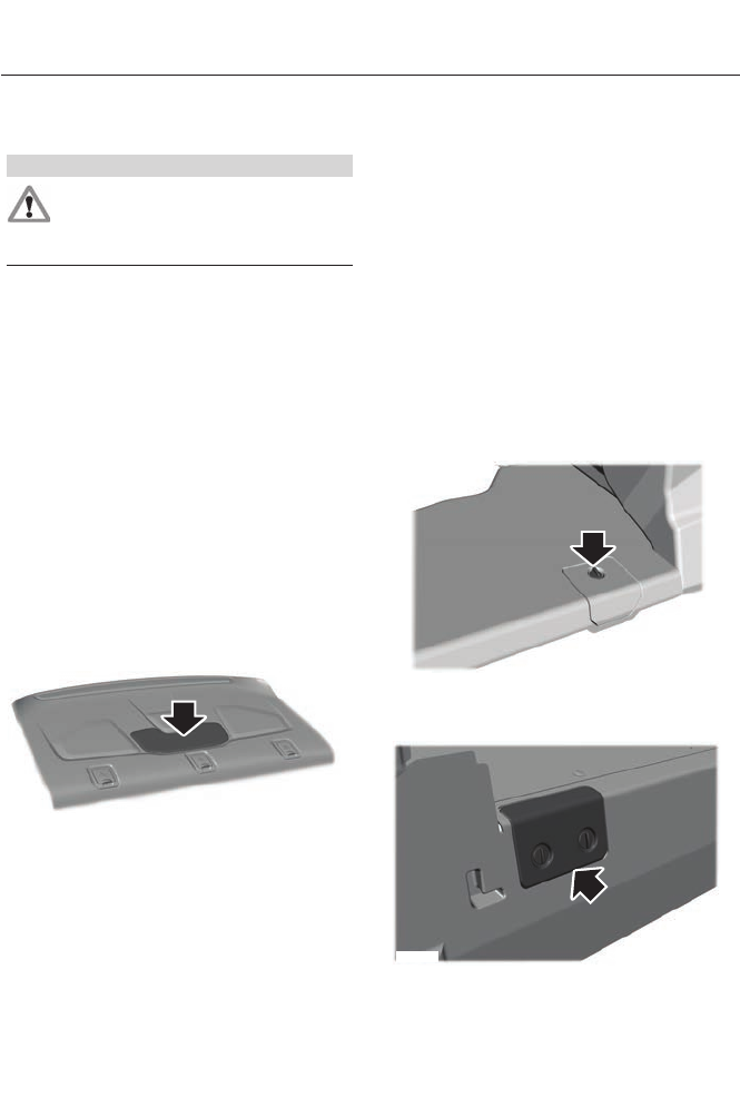
GENERAL INFORMATION
WARNING
This battery pack shall only be
serviced by an authorized electric
vehicle technician. Improper handling
can result in personal injury or death.
Note: The high-voltage battery does not
require regular service maintenance.
Your vehicle consists of various
high-voltage components and wiring. All
of the high-voltage power flows through
specific wiring assemblies which are
labeled as such or are covered with a solid
orange convolute, or orange striped tape,
or both. Do not come in contact with these
components.
The high-voltage battery system is a
high-voltage, lithium-ion battery system.
The pack is located in the rear cargo area.
The high-voltage battery system uses an
air cooled system to regulate the
high-voltage battery temperature and help
maximize high-voltage battery life.
E162457
Note: The high-voltage battery is equipped
with air vents in the package tray that help
to regulate its temperature. It is important
to keep these openings free of obstructions.
Do not block the flow of cabin air to this
area.
HIGH-VOLTAGE SERVICE
DISCONNECT
The high-voltage service disconnect shuts
off power from the high-voltage battery.
Note: There is a disconnect circuit in your
vehicle. Disconnecting the circuit will
automatically disable the high-voltage
battery.
To disable the battery and stop all
high-voltage electric activity in the vehicle
you can access high-voltage disconnect
circuit. To do this, you must unplug the
circuit from the circuit port connected to
the battery.
The high-voltage service disconnect is
located behind the rear fold down seats.
E159506
Service disconnect location for non-Energi
vehicles.
E162957
Service disconnect location for Energi
vehicles.
156
High Voltage Battery
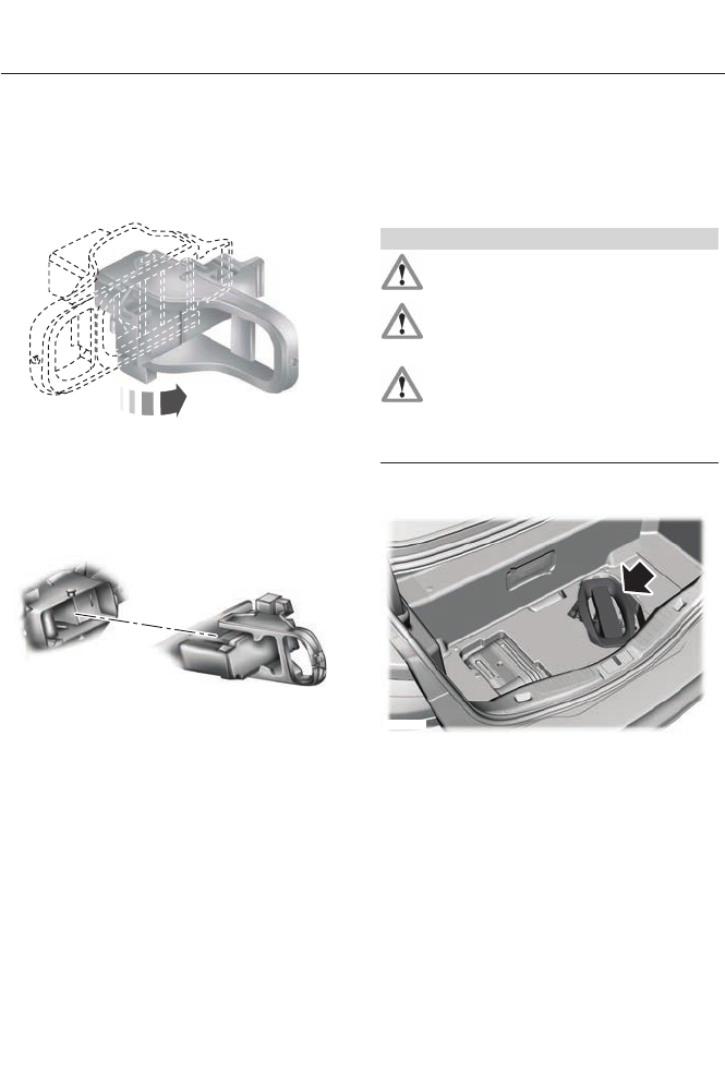
Disabling the High-Voltage Battery
1. Fold down the rear seats.
2. Locate the access door and remove
the plastic cover.
E147234
3. Slide the handle on the service
disconnect outboard to the right. For
Energi vehicles slide the handle
outboard and to the left.
E146133
4. Pull the handle toward you and remove
the circuit from the vehicle to disable
the high-voltage battery.
Reactivating the High-Voltage Battery
Note: If you have manually disconnected
your high-voltage shut off circuit you will
need to reconnect the circuit before it can
be reactivated. The vehicle will detect if the
electrical system is safe and reactivate
automatically.
CHARGING THE HIGH
VOLTAGE BATTERY
CHARGING THE HIGH-VOLTAGE
BATTERY (ENERGI VEHICLES)
WARNINGS
Do not use the 120-volt convenience
cord with extension cord or adapter.
In Canada, do not use the 120-volt
convenience cord in commercial
garages.
This equipment has arcing or
sparking parts that should not be
exposed to flammable vapors. This
equipment should be located at least 18
inches (80 millimeters) above the floor.
Charging Equipment
E163425
Your vehicle comes equipped with a
standard 120-volt convenience cord. Lift
the load floor carpet in the rear of the
vehicle to access the 120–volt convenience
cord.
Note: The 120–volt convenience cord
allows you to charge the high-voltage
battery using a standard 120-volt household
outlet. Using the standard 120-volt
convenience cord takes up to 7 hours to
completely charge from an empty battery.
157
High Voltage Battery
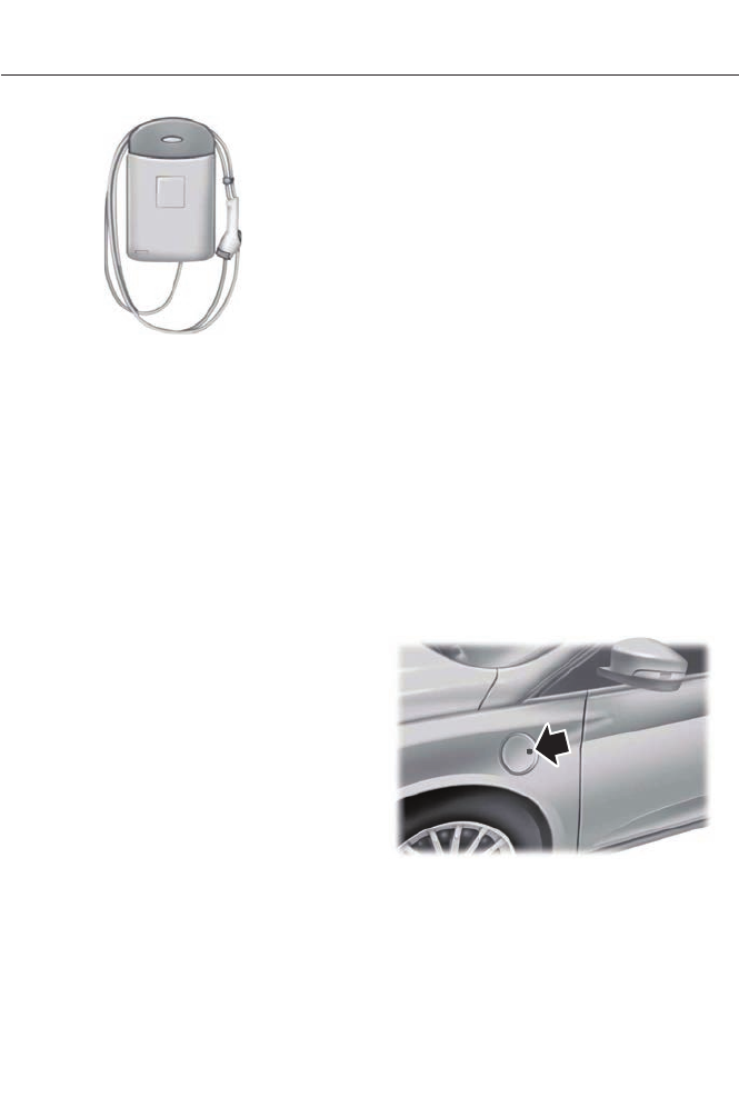
E145429
Ford recommends upgrading to the
optional 240-volt charging station for
faster more efficient charging. Use of a
240-volt charging station will take
approximately 2½ hours to fully charge a
empty battery.
Note: Your electrical source must meet
certain requirements for the high-voltage
batteries to charge. The AC outlet must be
a three-prong 110-120 volt AC outlet that is
properly grounded, 15–20 amps (or greater),
and in good condition. The line also must
be dedicated, which means that no other
appliances should be connected to the
same circuit. If a dedicated circuit is not
used, the circuit breaker could trip or open.
If a dedicated circuit is not available, contact
a licensed professional electrician for proper
installation.
Make sure that the 120–volt convenience
cord is completely unwound before
charging. Always plug the cord into the AC
outlet before connecting the charging
coupler into the vehicle’s charge port
receptacle. The 120–volt convenience cord
inline control box has three indicator lights
that represent the charging status; power,
charge and fault.
Power (green light)— this indicator lights
up when the cord is plugged into the AC
wall outlet.
Charge (green light)— indicates status
of charging:
• No light means the cord is not
connected to the vehicle.
• Blinking light means that the charging
is in process.
• Solid light means that the vehicle is
connected but not charging.
Fault (red triangle light)— Lights up in
case of a detected failure. No charging is
possible:
• Blinking red triangle light – means that
the 120–volt convenience cord is trying
to reset the failure and could restart
the charging cycle.
• Solid red triangle light – means that
the fault is permanent. The cord needs
to be unplugged and re-plugged to
reset the fault. If the fault persists,
contact your authorized dealer.
Charge Port
The charge port is located between the
front left side door and front left wheel
well. There is an indentation located on
the charge port door. Press with your
thumb to press to open and close the door.
E144779
Note: Do not force the charge port door
open or closed. Forcing the door open or
closed will damage the charge port.
158
High Voltage Battery

The light ring located around the charge
port indicates the charge status of your
vehicle's high-voltage battery. The charge
port light ring is divided into four quadrants
which display state of charge in 25 percent
increments.
There is a cord acknowledgment feature
that will be activated when a charge cycle
is initiated. The four light quadrants will
each individually flash clockwise starting
with the top right light and ending with the
top left, two full times confirming a
charging coupler has been detected.
You can use your keyfob to view the
vehicles charge status at any time by
pressing the unlock button. The light ring
will light up the corresponding quadrant(s)
so that the current state of charge can be
determined. If the charge is below 25
percent the light ring will not illuminate.
Don’t forget to press the lock button on
your keyfob to re-lock the vehicle.
The light ring will also display the current
state of charge when opening the doors.
Charging
Note: The vehicle must be in P (Park) to
charge.
To charge your high-voltage battery:
1. Put the vehicle in P (Park) and power
down the vehicle.
2. With your thumb, press the indentation
located on the charge port door and
the door will rotate open.
3. Plug the charging coupler into the
vehicles charge port receptacle and
make sure the button clicks confirming
that it is completely engaged.
E144780
4. Verify that the cord acknowledgment
feature activates. This indicates the
beginning of a normal charge cycle.
5. If using a 240–volt charging station,
follow the instructions on the charge
station to begin the charging process.
When charging, the light ring will display
how far along the charge is:
• When the top right quadrant is pulsing
the charge is between 0-25 percent.
• When the top right quadrant is solidly
lit and the bottom right quadrant is
pulsing the charge is between 25-50
percent.
• When both right side quadrants are
solidly lit and the bottom left quadrant
is pulsing the charge is between 50-75
percent.
• When three quadrants are solidly lit
and the top left quadrant is pulsing the
charge is between 75-100 percent.
• When the entire ring is solidly lit, the
charge is complete.
Note: The light ring will shut off one minute
after reaching a full charge.
Waiting to Charge
Note: See Charge Settings in the MyFord
Touch section. See MyFord Touch™ (page
348).
159
High Voltage Battery
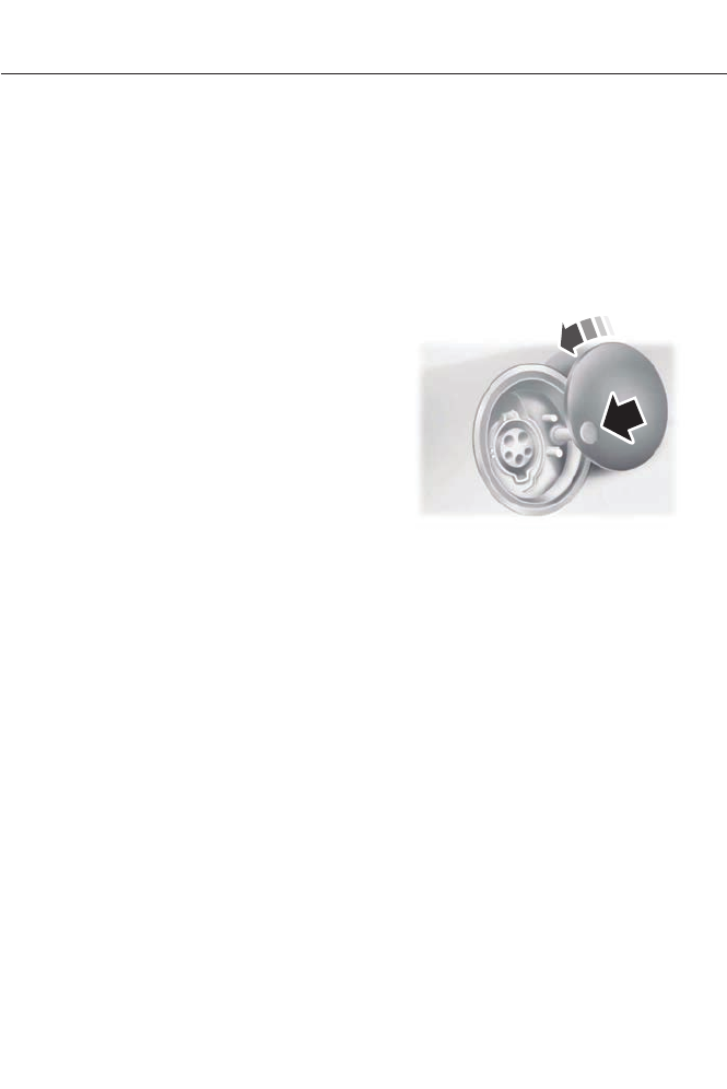
When Value Charge has been selected
charging may not begin upon plugging in.
The vehicle may delay charging to take
advantage of off-peak electricity rates. The
vehicle will optimize the charge schedule
to be complete by the next GO Time.
When waiting to charge (not actively
charging), the light ring will indicate the
present state of charge of the high voltage
battery as follows:
• When the top right quadrant is shut off
the charge is between 0–25 percent.
• When the top right quadrant is solidly
lit and the bottom right quadrant is
shut off the charge is between 25–50
percent.
• When both right side quadrants are
solidly lit and the bottom left quadrant
is shut off the charge is between 50–75
percent.
• When three quadrants are solidly lit
and the top left quadrant is shut off the
charge is between 75–100 percent.
• When the entire ring is solidly lit, the
charge is 100 percent.
Note: When the vehicle is Waiting to
Charge the light ring will shut off one minute
after displaying the present state of charge.
When the vehicle automatically begins
charging the light ring will turn on and
display how far along the charge is per the
section above.
Note: If a vehicle charging system fault is
detected at any point in a charge cycle the
entire light ring will flash continuously for
one minute and then shut off. If this
happens unplug, and then re-plug the
charging coupler into the charge port
receptacle. If the problem persists contact
your authorized dealer.
The light ring illumination conditions can
be modified. See Charge Port Light Ring
Settings in the MyFord Touch section. See
MyFord Touch™ (page 348).
Disconnecting the Charging Coupler
Note: Do not pull the wall plug from the
wall while the vehicle is charging. Doing so
may damage the outlet and the cord.
1. Press the button on the charging
coupler.
2. While holding the button, remove the
charging coupler from the vehicle’s
charge port receptacle.
E144781
3. Close the charge port door by pressing
the indentation on the charge port
door. Continue pressing the indentation
while the door rotates counter
clockwise and closes.
HIGH VOLTAGE BATTERY CUT-
OFF SWITCH
The high-voltage shut off operation shuts
off power from the high-voltage battery
after a collision, or if your vehicle receives
a substantial physical jolt.
To reactivate the vehicle after either event
perform the following steps:
1. Turn the ignition off.
2. Turn the ignition on.
3. If the vehicle is not powered after this
sequence, repeat steps 1 and 2.
For vehicles equipped with a push button
start system:
160
High Voltage Battery

1. Press the START/STOP button to
turn ignition off.
2. Press the brake pedal and press the
START/STOP button.
3. Remove your foot from the brake pedal
and press the START/STOP button
(ignition off).
4. Press the START/STOP button again
to re-enable the vehicle.
Note: After completing this process the
vehicle will detect if the electrical system is
safe and reactivate. Once your vehicle
determines the electrical system safe you
can start your vehicle as you would normally
by pressing the brake in combination with
the START/STOP button.
Note: In the event the vehicle does not
reactivate after the second key cycle,
contact an authorized dealer.
161
High Voltage Battery
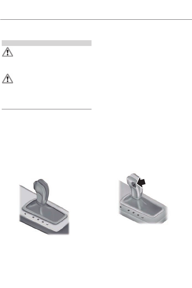
AUTOMATIC TRANSMISSION
WARNINGS
Always set the parking brake fully
and make sure the gearshift is
latched in P (Park). Turn the ignition
to the off position and remove the key
whenever you leave your vehicle.
Do not apply the brake pedal and
accelerator pedal simultaneously.
Applying both pedals simultaneously
for more than three seconds will limit
engine rpm, which may result in difficulty
maintaining speed in traffic and could lead
to serious injury.
Automatic Transmission
Putting your vehicle in gear:
1. Fully press down the brake pedal.
2. Press and hold the button on the front
of the gearshift lever.
3. Move the gearshift lever into the
desired gear.
4. Release the button and your
transmission will remain in the selected
gear.
E144820
P (Park)
This position locks the transmission and
prevents the front wheels from turning.
Come to a complete stop before putting
your vehicle into and out of P (Park)
R (Reverse)
With the gearshift lever in R (Reverse), the
vehicle will move backward. Always come
to a complete stop before shifting into and
out of R (Reverse).
N (Neutral)
With the gearshift lever in N (Neutral), the
vehicle is free to roll; hold the brake pedal
down while in this position.
D (Drive)
The normal driving position for the best
fuel economy.
D (Drive) with Grade Assist (If
Equipped)
Press the transmission control switch on
the side of the gearshift lever to activate
grade assist.
E146092
162
Transmission
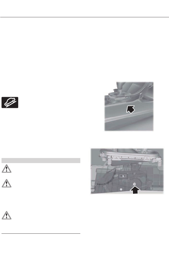
Grade assist:
• Provides additional grade braking with
a combination of engine motoring and
high-voltage battery charging to help
maintain vehicle speed when
descending a grade.
• As the vehicle determines the amount
of engine motoring and high-voltage
battery charging, you may notice the
engine speed increasing and
decreasing to help maintain your
vehicle speed when descending a
grade.
• The grade assist lamp in the instrument
cluster is illuminated.
E144523
The grade assist lamp will
appear in the instrument cluster
when grade assist is turned on.
Press the transmission control switch
again to return to normal D (Drive).
L (Low)
• Provides maximum engine braking.
• The transmission may be shifted into
L (Low) at any vehicle speed.
Brake-Shift Interlock
WARNINGS
Do not drive your vehicle until you
verify that the brake lamps are
working.
When doing this procedure, you will
be taking the vehicle out of park
which means the vehicle can roll
freely. To avoid unwanted vehicle
movement, always fully set the parking
brake prior to doing this procedure. Use
wheel chocks if appropriate.
If the parking brake is fully released,
but the brake warning lamp remains
illuminated, the brakes may not be
working properly. See your authorized
dealer.
Note: See your authorized dealer as soon
as possible if this procedure is used.
Note: For some markets this feature will be
disabled.
Use the brake shift interlock lever to move
the gearshift lever from the park position
in the event of an electrical malfunction or
if your vehicle has a dead battery.
Apply the parking brake and turn the
ignition off before performing this
procedure.
E155984
1. Remove the side panel on the right side
of the gearshift lever.
E155985
2. Locate the access hole.
163
Transmission
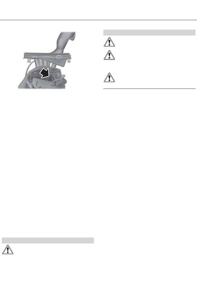
E155983
3. Insert the screwdriver (or similar tool)
into the access hole and press the lever
foreword while pulling the gearshift
lever out of the P (Park) position and
into the N (Neutral) position.
4. Remove the tool and reinstall the
panel.
5. Start the vehicle and release the
parking brake.
If Your Vehicle Gets Stuck In Mud
or Snow
Note: Do not rock the vehicle if the engine
is not at normal operating temperature or
damage to the transmission may occur.
Note: Do not rock the vehicle for more than
a minute or damage to the transmission and
tires may occur, or the engine may overheat.
If your vehicle gets stuck in mud or snow,
it may be rocked out by shifting between
forward and reverse gears, stopping
between shifts in a steady pattern. Press
lightly on the accelerator in each gear.
HILL START ASSIST
WARNINGS
The system does not replace the
parking brake. When you leave your
vehicle, always apply the parking
brake and put the vehicle in P (Park).
WARNINGS
You must remain in your vehicle once
you have activated the system.
During all times, you are responsible
for controlling your vehicle,
supervising the system and
intervening, if required.
If the engine is revved excessively, or
if a malfunction is detected, the
system will be deactivated.
The system makes it easier to pull away
when your vehicle is on a slope without the
need to use the parking brake.
When the system is active, your vehicle will
remain stationary on the slope for two to
three seconds after you release the brake
pedal. This allows you time to move your
foot from the brake to the accelerator
pedal. The brakes are released
automatically once the engine has
developed sufficient drive to prevent your
vehicle from rolling down the slope. This
is an advantage when pulling away on a
slope, (for example from a car park ramp,
traffic lights or when reversing uphill into
a parking space).
The system will activate automatically on
any slope which can result in significant
vehicle rollback.
Using Hill Start Assist
1. Press the brake pedal to bring your
vehicle to a complete standstill. Keep
the brake pedal pressed.
2. If the sensors detect that your vehicle
is on a slope, the system will be
activated automatically.
164
Transmission

3. When you remove your foot from the
brake pedal, your vehicle will remain
on the slope without rolling away for
approximately two or three seconds.
This hold time will automatically be
extended if you are in the process of
driving off.
4. Drive off in the normal manner. The
brakes will be released automatically.
165
Transmission
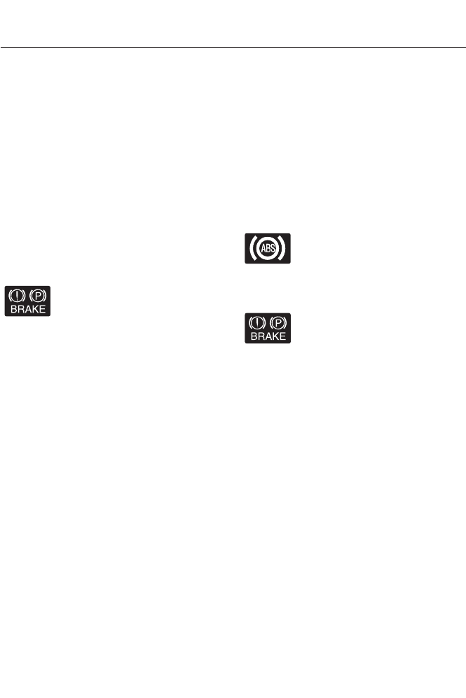
GENERAL INFORMATION
Note: Occasional brake noise is normal. If
a metal-to-metal, continuous grinding or
continuous squeal sound is present, the
brake linings may be worn-out and should
be inspected by an authorized dealer. If the
vehicle has continuous vibration or shudder
in the steering wheel while braking, the
vehicle should be inspected by an
authorized dealer.
Note: Brake dust may accumulate on the
wheels, even under normal driving
conditions. Some dust is inevitable as the
brakes wear and does not contribute to
brake noise. See Cleaning the Alloy
Wheels (page 257).
E144522
See Warning Lamps and
Indicators (page 80).
Wet brakes result in reduced braking
efficiency. Gently press the brake pedal a
few times when driving from a car wash or
standing water to dry the brakes.
Brake Over Accelerator
In the event the accelerator pedal
becomes stuck or entrapped, apply steady
and firm pressure to the brake pedal to
slow the vehicle and reduce engine power.
If you experience this condition, apply the
brakes and bring your vehicle to a safe
stop. Turn the engine off, shift to position
P and apply the parking brake, and then
inspect the accelerator pedal for any
interferences. If none are found and the
condition persists, have your vehicle towed
to the nearest authorized dealer.
Brake Assist
Brake assist detects when you brake
heavily by measuring the rate at which you
press the brake pedal. It provides
maximum braking efficiency as long as you
press the pedal. Brake assist can reduce
stopping distances in critical situations.
Anti-lock Brake System
This system helps you maintain steering
control during emergency stops by keeping
the brakes from locking.
This lamp momentarily
illuminates when the ignition is
turned on. If the light does not
illuminate during start up, remains on or
flashes, the anti-lock braking system may
be disabled and may need to be serviced.
E144522
If the system is disabled, normal
braking is still effective. If the
brake warning lamp illuminates
with the parking brake released, have your
brake system serviced immediately.
Regenerative Braking System
This feature is used to simulate the engine
braking of an internal combustion engine
and assist the standard brake system while
recovering some of the energy of motion
and storing it in the battery to improve fuel
economy. The standard brake system is
designed to fully stop the car if
regenerative braking is not available.
During regenerative braking, the motor is
spun as a generator to create electrical
current. This recharges the battery and
slows the vehicle. In effect, once the
accelerator pedal is released, the motor
changes from an energy user to an energy
producer.
166
Brakes
When the accelerator pedal is released or
the brake pedal is applied, the brake
controller automatically detects the
amount of deceleration requested and
optimizes how much of the deceleration
will be produced by regenerative braking.
The remaining portion is generated by
standard friction braking. When the battery
is almost fully charged, the amount of
regenerative braking is limited to avoid
overcharging, and the requested
deceleration is produced by standard
friction braking alone.
Regenerative braking does not take the
place of the standard friction brakes; it only
assists them. Regenerative braking has
also been designed to interact with the
anti-lock brake system. Regenerative
braking is disabled when the anti-lock
brake system is activated or the battery is
fully charged.
HINTS ON DRIVING WITH
ANTI-LOCK BRAKES
Note: When the system is operating, the
brake pedal will pulse and may travel
further. Maintain pressure on the brake
pedal. You may also hear a noise from the
system. This is normal.
The anti-lock braking system will not
eliminate the risks when:
• you drive too closely to the vehicle in
front of you
• your vehicle is hydroplaning
• you take corners too fast
• the road surface is poor.
ELECTRIC PARKING BRAKE
The electric parking brake replaces the
conventional handbrake. The operating
switch is located in the center console.
WARNING
Always set the parking brake and
leave your vehicle with the
transmission selector lever in
position P.
Note: When you apply the electric parking
brake in certain conditions, for example, on
a steep hill, the electric parking brake may
reapply the brakes within three to ten
minutes.
Note: You may notice various noises when
you apply and release the electric parking
brake. This is normal and no cause for
concern.
Applying the electric parking brake
WARNING
If the brake system warning lamp
does not illuminate or flashes, there
could be a problem with your electric
parking brake. Have the system checked
by an authorized dealer as soon as
possible.
Note: The brake system warning lamp will
illuminate for ten seconds, if the ignition is
turned off after the electric parking brake
has been applied, or the electric parking
brake has been applied after the ignition has
been turned off.
Note: The electric parking brake will not
automatically apply. You must apply the
electric parking brake using the electric
parking brake switch.
167
Brakes
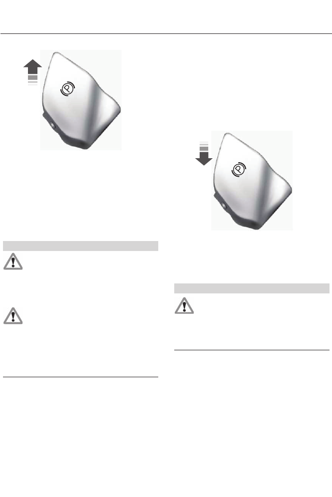
E147230
Pull the switch up to apply the electric
parking brake.
The brake system warning lamp will
illuminate to confirm that the electric
parking brake has been applied. See
Information Displays (page 84).
Applying the electric parking brake
when the vehicle is moving
WARNINGS
Applying the electric parking brake
while moving will result in use of the
anti-lock braking system. Do not use
the electric parking brake system when the
vehicle is moving unless the normal brake
system is unable to stop the vehicle.
With the exception of emergency
conditions (for example, the brake
pedal does not work or is blocked),
do not apply the electric parking brake
while the vehicle is moving. On bends, or
poor road surfaces or weather conditions,
emergency braking can cause the vehicle
to skid out of control or off the road.
If you apply the electric parking brake when
your vehicle is moving, the brake system
warning lamp will illuminate and a warning
chime will sound. See Information
Displays (page 84).
If your vehicle speed is above 4 mph (6
km/h), the braking force is applied ias long
as the switch is applied. Releasing or
pressing the switch or pressing the
accelerator pedal will stop the braking
force.
Releasing the electric parking
brake
E147231
You can release the electric parking brake
either manually by pressing the switch or
automatically.
Manual release
WARNING
If the brake system warning light
remains illuminated or flashes after
you have released the parking brake,
there could be a problem with you braking
system. Have the system checked by an
authorized dealer as soon as possible.
You can manually release the electric
parking brake by turning the ignition on,
pressing the brake pedal and then pressing
the electric parking brake switch.
When the electric parking brake is released,
the brake system warning lamp will turn
off.
168
Brakes

Automatic release - drive away release
Note: The driver's door must be closed and
the driver's safety belt must be fastened
before this feature will operate.
Note: If the electric parking brake warning
lamp stays illuminated, the electric parking
brake will not automatically release. You
must release the electric parking brake using
the electric parking brake switch.
Note: The engine must be running and the
accelerator pedal must be pressed before
the drive away release feature will operate.
Note: On hybrid vehicles, the vehicle must
be Ready-to-Drive as indicated by the green
Ready indicator light.
The brake system warning lamp will go off
to confirm that the electric parking brake
has been released.
Note: The electric parking brake drive away
release makes starting on a hill easier. This
feature will release the parking brake
automatically when the vehicle has
sufficient drive force to move up the hill. To
assure drive away release when starting
uphill, press the accelerator pedal quickly.
Battery With No Charge
WARNING
You will not be able to apply or
release the electric parking brake if
the battery is low or has no charge.
If the battery is low or has no charge, use
jumper cables and a booster battery.
169
Brakes
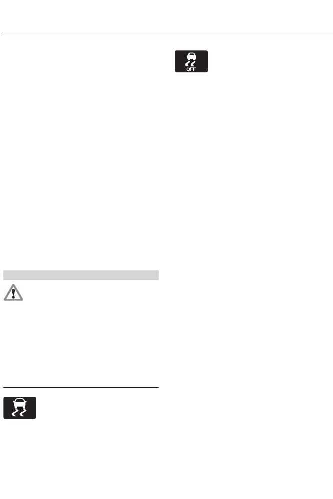
PRINCIPLE OF OPERATION
The traction control system helps avoid
drive wheel spin and loss of traction.
If your vehicle begins to slide, the system
applies the brakes to individual wheels
and, when needed, reduces engine power
at the same time. If the wheels spin when
accelerating on slippery or loose surfaces,
the system reduces engine power in order
to increase traction.
USING TRACTION CONTROL
In certain situations (for example, stuck in
snow or mud), turning the traction control
off may be beneficial as this allows the
wheels to spin with full engine power. Turn
off the traction control system through the
information display. See General
Information (page 84).
System Indicator Lights and
Messages
WARNING
If a failure has been detected within
the AdvanceTrac system, the
stability control light will illuminate
steadily. Verify that the AdvanceTrac
system was not manually disabled through
the information display. If the stability
control light still illuminates steadily, have
the system serviced by an authorized
dealer immediately. Operating your vehicle
with AdvanceTrac disabled could lead to
an increased risk of loss of vehicle control,
vehicle rollover, personal injury and death.
E138639
The stability control light
temporarily illuminates on
engine start-up and flashes
when a driving condition activates the
stability system.
The stability control off light
temporarily illuminates on
engine start-up and stays on
when you turn the traction control system
off.
When you turn the traction control system
off or on, a message appears in the
information display showing system status.
170
Traction Control
PRINCIPLE OF OPERATION
WARNINGS
Vehicle modifications involving
braking system, aftermarket roof
racks, suspension, steering system,
tire construction and wheel and tire size
may change the handling characteristics
of the vehicle and may adversely affect
the performance of the AdvanceTrac
system. In addition, installing any stereo
loudspeakers may interfere with and
adversely affect the AdvanceTrac system.
Install any aftermarket stereo loudspeaker
as far as possible from the front center
console, the tunnel, and the front seats in
order to minimize the risk of interfering with
the AdvanceTrac sensors. Reducing the
effectiveness of the AdvanceTrac system
could lead to an increased risk of loss of
vehicle control, vehicle rollover, personal
injury and death.
Remember that even advanced
technology cannot defy the laws of
physics. It’s always possible to lose
control of a vehicle due to inappropriate
driver input for the conditions. Aggressive
driving on any road condition can cause
you to lose control of your vehicle
increasing the risk of personal injury or
property damage. Activation of the
AdvanceTrac system is an indication that
at least some of the tires have exceeded
their ability to grip the road; this could
reduce the operator’s ability to control the
vehicle potentially resulting in a loss of
vehicle control, vehicle rollover, personal
injury and death. If your AdvanceTrac
system activates, SLOW DOWN.
The AdvanceTrac Control system helps
you keep control of your vehicle when on
a slippery surface. The electronic stability
control portion of the system helps avoid
skids and lateral slides. The traction
control system helps avoid drive wheel
spin and loss of traction. See Using
Traction Control (page 170).
E72903
AA
A
B
B
B
B
Vehicle without AdvanceTrac
skidding off its intended route.
A
Vehicle with AdvanceTrac
maintaining control on a slippery
surface.
B
USING STABILITY CONTROL
AdvanceTrac®
The system automatically activates when
you start your engine. The AdvanceTrac
system cannot be completely turned off,
but the electronic stability control system
is disabled when the transmission selector
lever is in position R. You can turn off the
traction control portion of the system
independently. See Using Traction
Control (page 170).
171
Stability Control
PARKING AID (IF EQUIPPED)
WARNINGS
To help avoid personal injury, please
read and understand the limitations
of the system as contained in this
section. Sensing is only an aid for some
(generally large and fixed) objects when
moving in reverse on a flat surface at
parking speeds. Traffic control systems,
inclement weather, air brakes, and external
motors and fans may also affect the
function of the sensing system; this may
include reduced performance or a false
activation.
To help avoid personal injury, always
use caution when in R (Reverse) and
when using the sensing system.
This system is not designed to
prevent contact with small or moving
objects. The system is designed to
provide a warning to assist the driver in
detecting large stationary objects to avoid
damaging the vehicle. The system may not
detect smaller objects, particularly those
close to the ground.
Certain add-on devices such as large
trailer hitches, bike or surfboard racks
and any device that may block the
normal detection zone of the system, may
create false beeps.
Note: Keep the sensors, located on the
bumper or fascia, free from snow, ice and
large accumulations of dirt. If the sensors
are covered, the system’s accuracy can be
affected. Do not clean the sensors with
sharp objects.
Note: If your vehicle sustains damage to
the bumper or fascia, leaving it misaligned
or bent, the sensing zone may be altered
causing inaccurate measurement of
obstacles or false alarms.
Note: If your vehicle is equipped with
MyKey®, it is possible to prevent turning the
sensing system off. See MyKey™ (page
48).
The sensing system warns the driver of
obstacles within a certain range of the
bumper area. The system turns on
automatically whenever the ignition is
switched on.
When receiving a detection warning, the
radio volume is reduced to a
predetermined level. After the warning
goes away, the radio volume returns to the
previous level.
The system can be switched off through
the information display menu or from the
pop-up message that appears once the
transmission is shifted into R. See General
Information (page 84).
If a fault is present in the system, a warning
message appears in the information
display and does not allow the driver to
switch the faulted system on. See
Information Messages (page 96).
Rear Sensing System
The rear sensors are only active when the
transmission is in R. As the vehicle moves
closer to the obstacle, the rate of the
audible warning increases. When the
obstacle is fewer than 10 inches (25
centimeters) away, the warning sounds
continuously. If a stationary or receding
object is detected farther than 10 inches
(25 centimeters) from the side of the
vehicle, the tone sounds for only three
seconds. Once the system detects an
object approaching, the warning sounds
again.
172
Parking Aids
E130178
A
Coverage area of up to 6 feet (2
meters) from the rear bumper.
There is decreased coverage
area at the outer corners of the
bumper.
A
The system detects certain objects while
the transmission is in R:
• and moving toward a stationary object
at a speed of 3 mph (5 km/h) or less
• but not moving, and a moving object is
approaching the rear of the vehicle at
a speed of 3 mph (5 km/h) or less
• and moving at a speed of less than 3
mph (5 km/h) and a moving object is
approaching the rear of the vehicle at
a speed of less than 3 mph (5 km/h).
Front Sensing System
The front sensors are active when the
gearshift is in any position other than P
(Park) or N (Neutral) and the vehicle speed
is below 6 mph (10 km/h).
E130382
A
Coverage area of up to 27 inches
(70 centimeters) from the front
of the vehicle and about 6–14
inches (15–35 centimeters) to
the side of the front end of the
vehicle. Refer to the reverse
sensing section for details on
coverage area.
A
The system sounds an audible warning
when obstacles are near either bumper in
the following manner:
• Objects detected by the front sensors
are indicated by a high-pitched tone
from the front radio speakers.
• Objects detected by the rear sensors
are indicated by a lower pitched tone
from the rear radio speakers.
• The sensing system reports the
obstacle which is closest to the front
or rear of the vehicle. For example, if
an obstacle is 24 inches (60
centimeters) from the front of the
vehicle and, at the same time, an
obstacle is only 16 inches (40
centimeters) from the rear of the
vehicle, the lower pitched tone sounds.
• An alternating warning sounds from
the front and rear if there are objects
at both bumpers that are closer than
10 inches (25 centimeters).
173
Parking Aids
For specific information on the reverse
sensing portion of the system, refer to that
section.
ACTIVE PARK ASSIST (IF
EQUIPPED)
WARNING
This system is designed to be a
supplementary park aid. It may not
work in all conditions and is not
intended to replace the driver’s attention
and judgment. The driver is responsible for
avoiding hazards and maintaining a safe
distance and speed, even when the system
is in use.
Note: The driver is always responsible for
controlling the vehicle, supervising the
system and intervening if required.
The system detects an available parallel
parking space and automatically steers
the vehicle into the space (hands-free)
while you control the accelerator, gearshift
and brakes. The system visually and
audibly instructs you to park the vehicle.
The system may not function correctly if
something passes between the front
bumper and the parking space (i.e. a
pedestrian or cyclist) or if the edge of the
neighboring parked vehicle is high from the
ground (i.e. a bus, tow truck or flatbed
truck).
Note: The sensors may not detect objects
in heavy rain or other conditions that cause
disruptive reflections.
Note: The sensors may not detect objects
with surfaces that absorb ultrasonic waves.
The system should not be used if:
• a foreign object (i.e. bike rack or trailer)
is attached to the front or rear of the
vehicle or at another location close to
the sensors.
• an overhanging object (i.e. surfboard)
is attached to the roof.
• the front bumper or side sensors are
damaged (i.e. in a collision) or
obstructed by a foreign object (i.e. front
bumper cover).
• a mini-spare tire is in use.
Using Active Park Assist
E146186
Press the button located on the
center console near the gearshift
lever.
The touch screen displays a message and
a corresponding graphic to indicate it's
searching for a parking space. Use the turn
signal to indicate which side of the vehicle
you want the system to search on.
Note: If the turn signal is not on, the system
automatically searches on the vehicle's
passenger side.
A
E130107
174
Parking Aids
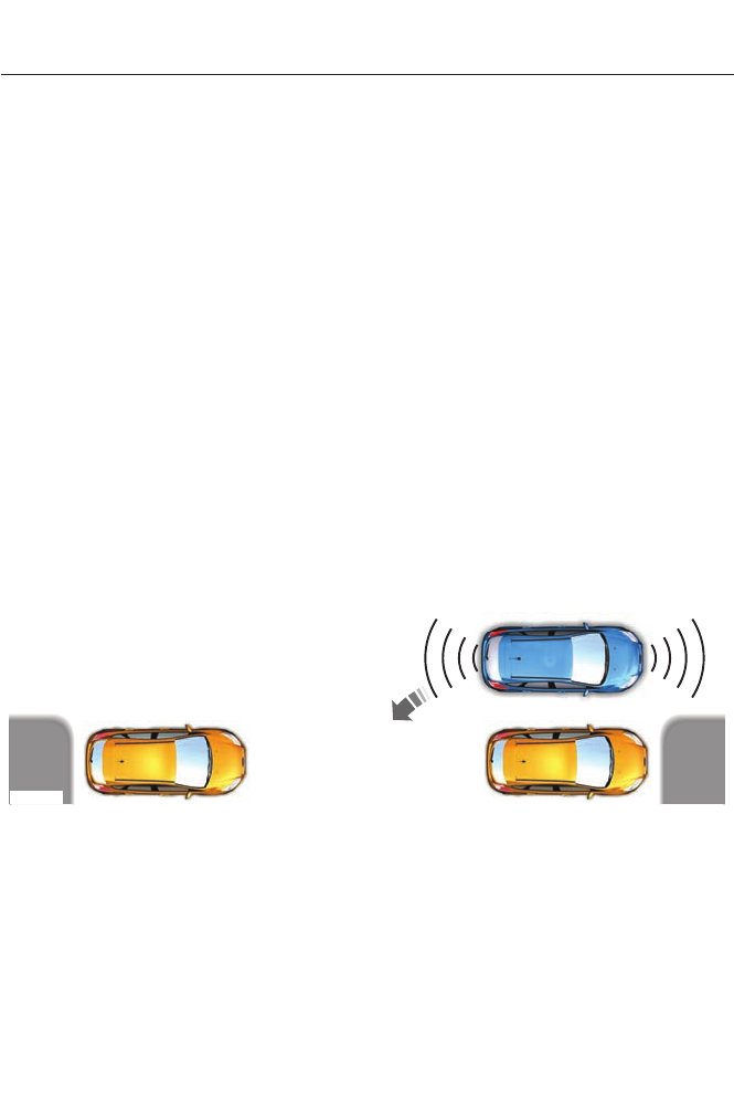
When a suitable space is found, the touch
screen displays a message and a chime
sounds. Slow down and stop at
approximately position (A), then follow
the instructions on the touch screen.
Note: You must observe that the selected
space remains clear of obstructions at all
times in the maneuver.
Note: Vehicles with overhanging loads (e.g.
a bus or a truck), street furniture and other
items may not be detected by active park
assist. You must make sure the selected
space is suitable for parking.
Note: The vehicle should be driven as
parallel to other vehicles as possible while
passing a parking space.
Note: The system always offers the last
detected parking space (i.e. if the vehicle
detects multiple spaces while you are
driving, it offers the last one).
Note: If driven above approximately 20
mph (35 km/h), the touch screen shows a
message to alert you to reduce vehicle
speed.
Automatic Steering into Parking
Space
Note: If vehicle speed exceeds 6 mph (10
km/h), the system switches off and you
need to take full control of the vehicle.
Note: If a maneuver is interrupted before
completion, the system switches off. The
steering wheel position will not indicate the
actual position of the steering and you have
to full take control of the vehicle.
With your hands off the wheel (and
nothing obstructing its movement) and
the transmission in R (Reverse), the vehicle
steers itself as instructions to safely move
the vehicle back and forward in the space
are displayed in the touch screen. While
reversing, the touch screen displays a
message instructing you to check your
surroundings (for safety reasons) and to
back-up slowly, accompanied by a
corresponding graphic.
E130108
When you think the vehicle has enough
space in front and behind it, or you hear a
solid tone from the parking aid, bring the
vehicle to a complete stop.
When automatic steering is finished, the
touch screen displays a message indicating
that the active park assist process is done.
The driver is responsible for checking the
parking job and making any necessary
corrections.
175
Parking Aids

Deactivating the Park Assist
Feature
The system can be deactivated manually
by:
• pressing the active park assist button
• grabbing the steering wheel
• driving above approximately 20 mph
(35 km/h) for 30 seconds during an
active park search
• driving above 6 mph (10 km/h) during
automatic steering
• turning off the traction control system.
Certain vehicle conditions can also
deactivate the system, such as:
• Traction control has activated on a
slippery or loose surface.
• There is an anti-lock brake system
activation or failure.
• Something touches the steering wheel.
If a problem occurs with the system, a
warning message is displayed, followed
by a chime. Occasional system messages
may occur in normal operation. For
recurring or frequent system faults, contact
an authorized dealer to have your vehicle
serviced.
Troubleshooting the System
The system does not look for a space
The traction control system may be off
The system does not offer a particular space
Something may be contacting the front bumper or side sensors
There is not enough room on both sides of the vehicle in order to park
There is not enough space for the parking maneuver on the opposite side of the parking
space
The vehicle is farther than 5 ft (1.5 m) from the parking space
The vehicle is closer than 16 in. (40 cm) from neighboring parked vehicles
The transmission is in R (Reverse); the vehicle must be moving forward to detect a
parking space
176
Parking Aids
The system does not position the vehicle where I want in the space
The vehicle is rolling in the opposite direction of the transmission (i.e. rolling forward
when R [Reverse] is selected)
The transmission is in R (Reverse); the vehicle must be moving forward to detect a
parking space
An irregular curb along the parking space prevents the system from aligning the vehicle
properly
Vehicles or objects bordering the space may not be positioned correctly
The vehicle was pulled too far past the parking space. The system performs best when
you drive the same distance past the parking space
The tires may not be installed or maintained correctly (i.e. not inflated correctly, improper
size, or of different sizes)
A repair or alteration has changed detection capabilities
A parked vehicle has a high attachment (i.e. salt sprayer, snowplow, moving truck bed,
etc.)
The parking space length or position of parked objects changed after your vehicle passed
The temperature around your vehicle changes quickly (i.e. driving from a heated garage
into the cold, or after leaving a car wash)
REAR VIEW CAMERA (IF EQUIPPED)
WARNINGS
The rear view camera system is a
reverse aid supplement device that
still requires the driver to use it in
conjunction with the interior and exterior
mirrors for maximum coverage.
Objects that are close to either
corner of the bumper or under the
bumper, might not be seen on the
screen due to the limited coverage of the
camera system.
Back up as slow as possible since
higher speeds might limit your
reaction time to stop the vehicle.
WARNINGS
Use caution when using the rear
video camera and the trunk is ajar. If
the trunk is ajar, the camera will be
out of position and the video image may
be incorrect. All guidelines (if enabled)
have been removed when the trunk is ajar.
Use caution when turning camera
features on or off while in R
(Reverse). Make sure the vehicle is
not moving.
The rear view camera system provides a
video image of the area behind the vehicle.
The image will be displayed in either in the
rear view mirror or the display in the center
of the instrument panel.
177
Parking Aids

During operation, lines appear in the
display which represent your vehicle’s path
and proximity to objects behind the vehicle.
E142435
The camera is located on the trunk.
Using the Rear View Camera
System
The rear view camera system displays
what is behind your vehicle when you place
the transmission in R (Reverse).
The system uses three types of guides to
help you see what is behind your vehicle:
• Active guidelines: Show the intended
path of your vehicle when reversing.
• Fixed guidelines: Show the actual path
your vehicle is moving in while reversing
in a straight line. This can be helpful
when backing into a parking space or
aligning your vehicle with another
object behind you.
• Centerline (If applicable): Helps align
the center of your vehicle with an
object (i.e. a trailer).
Note: If the transmission is in R (Reverse)
and the luggage compartment is ajar, no
rear view camera features are displayed.
Note: If the image comes on while the
transmission is not in R (Reverse), have the
system inspected by your authorized dealer.
Note: When towing, the camera only sees
what is being towed behind your vehicle.
This might not provide adequate coverage
as it usually provides in normal operation
and some objects might not be seen. In
some vehicles, the guidelines may disappear
once the trailer tow connector is engaged.
Note: The camera may not operate
correctly under the following conditions:
• Nighttime or dark areas if one or both
reverse lamps are not operating.
• The camera's view is obstructed by
mud, water or debris. Clean the lens
with a soft, lint-free cloth and
non-abrasive cleaner.
• The rear of the vehicle is hit or
damaged, causing the camera to
become misaligned.
To access any of the rear view camera
system settings, make the following
selections in the touch screen when the
transmission is not in R (Reverse):
• Menu > Vehicle > Rear View Camera
After changing a system setting, the touch
screen shows a preview of the selected
features.
Guidelines and the Centerline
Note: Active guidelines and fixed guidelines
are only available when the transmission is
in R (Reverse).
Note: The centerline is only available if
Active or Fixed guidelines are on.
178
Parking Aids
A B C D
F
E
E142436
Active guidelinesA
CenterlineB
Fixed guideline: Green zoneC
Fixed guideline: Yellow zoneD
Fixed guideline: Red zoneE
Rear bumperF
Active guidelines are only shown with fixed
guidelines. To use active guidelines, turn
the steering wheel to point the guidelines
toward an intended path. If the steering
wheel position is changed while reversing,
the vehicle might deviate from the original
intended path.
The fixed and active guidelines fade in and
out depending on the steering wheel
position. The active guidelines are not
shown when the steering wheel position
is straight.
Always use caution while reversing.
Objects in the red zone are closest to your
vehicle and objects in the green zone are
farther away. Objects are getting closer to
your vehicle as they move from the green
zone to the yellow or red zones. Use the
side view mirrors and rear view mirror to
get better coverage on both sides and rear
of the vehicle.
Selectable settings for this feature are
ACTIVE + FIXED, FIXED and OFF.
Visual Park Aid Alert
Note: Visual park alert is only available
when the transmission is in R (Reverse).
Note: The reverse sensing system is not
effective at speeds above 3 mph (5 km/h)
and may not detect certain angular or
moving objects.
The system uses red, yellow and green
highlights which appear on top of the video
image when an object is detected by the
reverse sensing system. The alert highlights
the closest object detected. The reverse
sensing alert can be disabled and if visual
park aid alert is enabled, highlighted areas
are still displayed.
Selectable settings for this feature are ON
and OFF.
Manual Zoom
WARNING
When manual zoom is on, the full
area behind the vehicle is not shown.
Be aware of your surroundings when
using the manual zoom feature.
Note: Manual zoom is only available when
the transmission is in R (Reverse).
Note: When manual zoom is enabled, only
the centerline is shown.
179
Parking Aids

This allows you to get a closer view of an
object behind the vehicle. The zoomed
image keeps the bumper in the image to
provide a reference. The zoom is only
active while the transmission is in R
(Reverse). When the transmission is
shifted out of R (Reverse), the feature
automatically turns off and must be reset
when it is used again.
Selectable settings for this feature are OFF,
Level 1, Level 2 or Level 3. Press the up and
down arrows to change the view. The
selection level appears between the
buttons (i.e. Level 1). The default setting
for the manual zoom is OFF.
Rear Camera Delay
The camera image will be displayed upon
shifting out of R (Reverse) until the vehicle
speed reaches 5 mph (8 km/h). This will
occur when the rear camera delay feature
is on, or until the radio button is selected.
Selectable settings for this feature are ON
and OFF. The default setting for the rear
camera delay is OFF.
180
Parking Aids
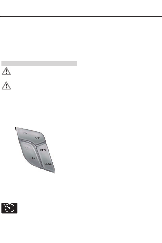
PRINCIPLE OF OPERATION
Cruise control lets you maintain a set
speed without keeping your foot on the
accelerator pedal.
USING CRUISE CONTROL
WARNINGS
Do not use cruise control in heavy
traffic, on winding roads or when the
road surface is slippery.
When you are going downhill, your
speed may increase above the set
speed. The system will not apply the
brakes. Change down a gear to assist the
system in maintaining the set speed.
Note: Cruise control will disengage if the
vehicle speed decreases more than 10 mph
(16 km/h) below your set speed while
driving uphill.
E144500
The cruise controls are located on the
steering wheel.
Switching Cruise Control On
Press and release ON.
E71340
The indicator will appear in the
instrument cluster.
Setting a Speed
1. Accelerate to the desired speed.
2. Press and release SET+.
3. Take your foot off the accelerator
pedal.
The indicator will change colors in the
instrument cluster.
Changing the Set Speed
Note: If you accelerate by pressing the
accelerator pedal, the set speed will not
change. When you release the accelerator
pedal, you will return to the speed that you
previously set.
• Press and hold SET+ or SET-. Release
the control when you reach the desired
speed.
• Press and release SET+ or SET-. The
set speed will change in approximately
1 mph (2 km/h) increments.
• Press the accelerator or brake pedal
until you reach the desired speed. Press
and release SET+.
Canceling the Set Speed
Press CNCL or tap the brake pedal. You
will not erase the set speed.
Resuming the Set Speed
Press and release RES.
Switching Cruise Control Off
Note: You will erase the set speed if you
switch the system off.
Press and release OFF or switch the
ignition off.
181
Cruise Control
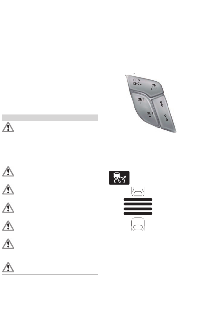
ECO Cruise Control
This feature saves vehicle energy by
relaxing acceleration compared to
standard cruise control. For example, your
vehicle may temporarily lose speed when
going uphill. ECO will appear in the
information display when ECO cruise
control is activated. It can be switched on
or off in the information display. See
General Information (page 84).
USING ADAPTIVE CRUISE
CONTROL (IF EQUIPPED)
WARNINGS
Always pay close attention to
changing road conditions, especially
when using adaptive cruise control.
Adaptive cruise control cannot replace
attentive driving. Failing to follow any of
the warnings below or failing to pay
attention to the road may result in a
collision, serious injury or death.
Adaptive cruise control is not a
collision warning or avoidance
system.
Adaptive cruise control will not
detect stationary or slow moving
vehicles below 6 mph (10 km/h).
Adaptive cruise control will not
detect pedestrians or objects in the
roadway.
Adaptive cruise control will not
detect oncoming vehicles in the
same lane.
Do not use the adaptive cruise
control when entering or leaving a
highway, in heavy traffic or on roads
that are winding, slippery or unpaved.
Do not use in poor visibility,
specifically fog, rain, spray or snow.
Note: It is your responsibility to stay alert,
drive safely and be in control of the vehicle
at all times.
The system adjusts your speed to maintain
a proper distance between you and the
vehicle in front of you in the same lane. You
can select from one of four gap settings.
E144501
The controls for using your cruise control
are located on the steering wheel.
Switching the System On
Press and release ON.
E144529
The information display will
show the grey indicator light.
E164805
The current gap setting and SET will also
display.
Setting a Speed
1. Accelerate to the desired speed.
2. Press and release SET+. The vehicle
speed will be stored in the memory.
182
Cruise Control
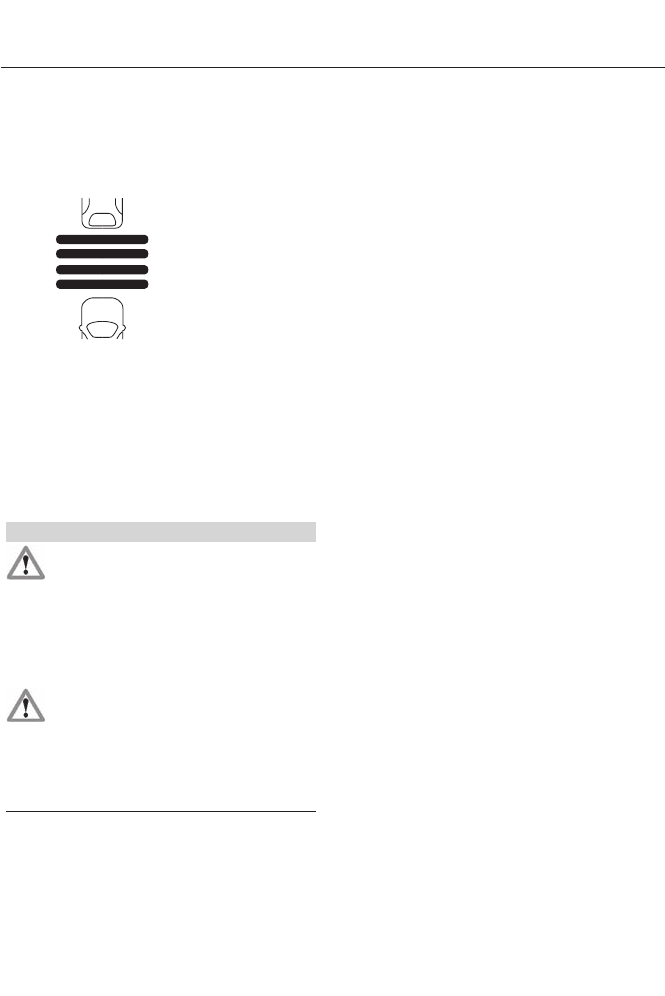
3. The information display will show a
green indicator light, current gap
setting and desired set speed.
4. Take your foot off the accelerator
pedal.
E164805
5. A lead vehicle graphic will illuminate if
there is a vehicle detected in front of
you.
Note: When adaptive cruise control is
active, the set speed displayed in the
information display may vary slightly from
the speedometer.
Following a Vehicle
WARNINGS
When following a vehicle in front of
you, the vehicle will not decelerate
automatically to a stop, nor will the
vehicle always decelerate quickly enough
to avoid a collision without driver
intervention. Always apply the brakes when
necessary. Failing to do so may result in a
collision, serious injury or death.
Adaptive cruise control only warns
of vehicles detected by the radar
sensor. In some cases there may be
no warning or the warning may be delayed.
The driver should always apply the brakes
when necessary. Failing to do so may result
in a collision, serious injury or death.
Note: The brakes may emit a sound when
they are being modulated by the adaptive
cruise control system.
When a vehicle ahead of you enters the
same lane or a slower vehicle is ahead in
the same lane, the vehicle speed adjusts
to maintain a preset gap distance. The
distance setting is adjustable.
The lead vehicle graphic will illuminate.
The vehicle will maintain a constant
distance between the vehicle ahead until:
• the vehicle in front of you accelerates
to a speed above the set speed
• the vehicle in front of you moves out of
your lane or out of view
• the vehicle speed falls below 12 mph
(20 km/h)
• a new gap distance is set.
The vehicle will apply the brakes to slow
the vehicle to maintain a safe distance
from the vehicle in front. The maximum
braking which the system can apply is
limited. You can override the system by
applying the brakes.
If the system predicts that its maximum
braking level will not be sufficient, an
audible warning will sound while the
system continues to brake. This is
accompanied by a heads-up display; a red
warning bar illuminating on the windshield.
You should take immediate action.
Setting the Gap Distance
Note: It is your responsibility to select a gap
appropriate to the driving conditions.
183
Cruise Control
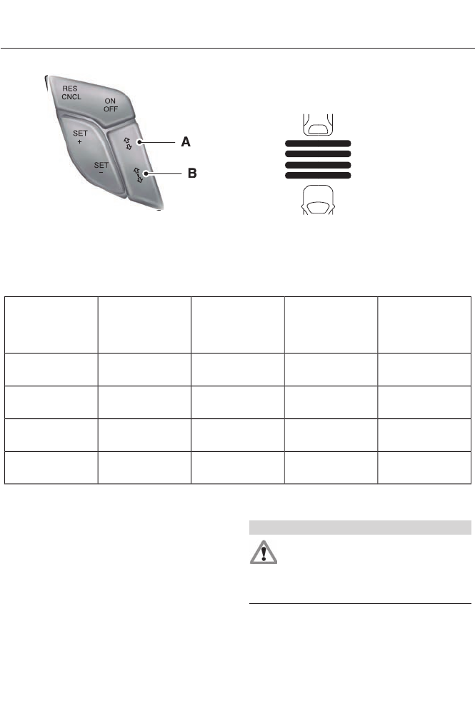
E144502
Gap decreaseA
Gap increaseB
You can decrease or increase the distance
between your vehicle and the vehicle in
front of you by pressing the gap control.
E164805
The selected gap displays in the message
center as shown by the bars in the graphic.
Four gap distance settings are available.
Adaptive cruise control, distance between vehicle settings
Dynamic Beha-
vior
Distance GapTime Gap,
Seconds
Graphic Display,
Bars Indicated
Between
Vehicles
Set Speed
yd (m)mph ( km/h)
Sport31 yd (28 m)1162 mph
(100 km/h)
Normal43 yd (39 m)1.4262 mph
(100 km/h)
Normal55 yd (50 m)1.8362 mph
(100 km/h)
Comfort67 yd (61 m)2.2462 mph
(100 km/h)
Each time you start the vehicle, the system
will select the last chosen gap for the
current driver.
Disengaging the System
Press the brake pedal or press CNCL. The
last set speed will display with a
strikethrough but will not erase.
Overriding the System
WARNING
Whenever the driver is overriding the
system by pressing the accelerator
pedal, the system will not
automatically apply the brakes to maintain
separation from any vehicle ahead.
You can override the set speed and gap
distance by pressing the accelerator pedal.
184
Cruise Control

E144529
When you override the system
the green indicator light
illuminates and the follow
vehicle does not show in the
information display.
The system will resume operation when
you release the accelerator pedal. The
vehicle speed will decrease to the set
speed, or a lower speed if following a
slower vehicle.
Changing the Set Speed
• Accelerate or brake to the desired
speed, then press and release SET+.
• Press and hold SET+ or SET- until the
desired set speed shows on the
information display. The vehicle speed
will gradually change to the selected
speed.
• Press and release SET+ or SET-. The
set speed will change in approximately
1 mph (2 km/h) increments.
The system may apply the brakes to slow
the vehicle to the new set speed. The set
speed will display continuously in the
information display while the system is
active.
Resuming the Set Speed
Note: Only use resume if you are aware of
the set speed and intend to return to it.
Press and release RES. The vehicle will
return to the previously set speed. The set
speed will display continuously in the
information display while the system is
active.
Low Speed Automatic
Cancellation
The system is not functional at vehicle
speeds below 12 mph (20 km/h). An
audible alarm will sound and the
automatic braking releases if the vehicle
drops below this speed.
Hilly Condition Usage
Note: An audible alarm will sound and the
system will shut down if it is applying brakes
for an extended period of time. This allows
the brakes to cool down. The system will
function normally again when the brakes
have cooled down.
You should select a lower gear position
when the system is active in situations
such as prolonged downhill driving on
steep grades, for example in mountainous
areas. The system needs additional engine
braking in these situations to reduce the
load on the vehicle’s regular brake system
to prevent them from overheating.
Switching the System Off
Note: The set speed memory erases when
you switch off the system.
Press and release OFF or turn off the
ignition.
Detection Issues
The radar sensor has a limited field of
vision. It may not detect vehicles at all or
detect a vehicle later than expected in
some situations. The lead vehicle graphic
will not illuminate if the system does not
detect a vehicle in front of you.
185
Cruise Control
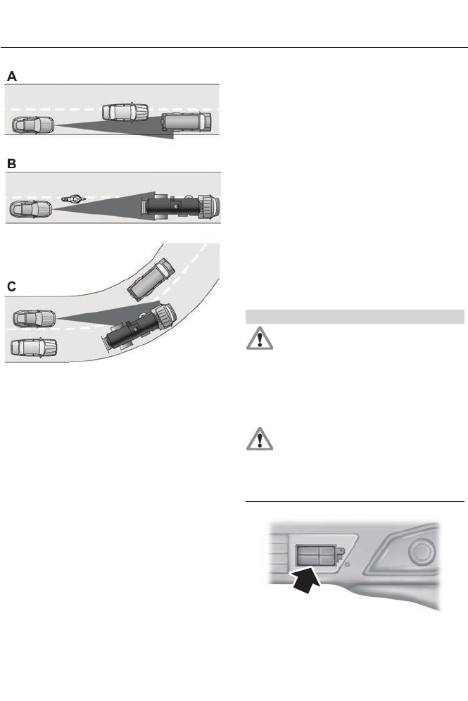
E71621
Detection issues can occur:
When driving on a different line
than the vehicle in front.
A
With vehicles that edge into your
lane. The system can only detect
these vehicles once they move
fully into your lane.
B
There may be issues with the
detection of vehicles in front
when driving into and coming out
of a bend or curve in the road.
C
In these cases, the system may brake late
or unexpectedly. The driver should stay
alert and intervene when necessary.
If something hits the front end of your
vehicle or damage occurs, the
radar-sensing zone may change. This could
cause missed or false vehicle detections.
See an authorized dealer to have the radar
checked for proper coverage and
operation.
System Not Available
Conditions which can cause the system to
deactivate or prevent the system from
activating when requested include:
• a blocked sensor
• high brake temperature
• a failure in the system or a related
system.
Blocked Sensor
WARNINGS
Do not use the system when towing
a trailer with brake controls.
Aftermarket trailer brakes will not
function properly when the system is
activated because the brakes are
electronically controlled. Failing to do so
may result in loss of vehicle control, which
could result in serious injury.
Do not use tires sizes other than
those recommended because this
can affect the normal operation of
the system. Failing to do so may result in
a loss of vehicle control, which could result
in serious injury.
E145632
186
Cruise Control
A message displays if something obstructs
the radar signals from the sensor. The
sensor is located behind a fascia cover
near the driver side of the lower grille. The
system cannot detect a vehicle ahead and
will not function when something obstructs
the radar signals. The following table lists
possible causes and actions for this
message displaying.
ActionCause
Clean the grille surface in front of the radar
or remove the object causing the obstruc-
tion.
The surface of the radar in the grille is dirty
or obstructed in some way.
Wait a short time. It may take several
minutes for the radar to detect that it is no
longer obstructed
The surface of the radar in the grille is clean
but the message remains in the display.
Do not use the system in these conditions
because it may not detect any vehicles
ahead.
Heavy rain or snow is interfering with the
radar signals.
Do not use the system in these conditions
because it may not detect any vehicles
ahead.
Swirling water, or snow or ice on the surface
of the road may interfere with the radar
signals.
Wait a short time or switch to normal cruise
control.
You are in a desert or remote area with no
other vehicles and no roadside objects.
Due to the nature of radar technology, it is
possible to get a blockage warning and not
be blocked. This can happen, for example,
when driving in sparse rural or desert
environments. A false blocked condition
will either self clear or clear after a key
cycle.
Switching to Normal Cruise
Control
WARNING
Normal cruise control will not brake
due to slower vehicles. Always be
aware of which mode is selected and
apply the brakes when necessary.
You can manually change from adaptive
cruise control to normal cruise control
through the information display.
E71340
The cruise control indicator light
replaces the adaptive cruise
control indicator light if you
select normal cruise control. The gap
setting will not display, the system will not
automatically respond to lead vehicles and
automatic braking will activate. The
system defaults to adaptive cruise control
when you start the vehicle.
ECO Cruise Control
This feature saves vehicle energy by
relaxing acceleration compared to
standard cruise control. For example, your
vehicle may temporarily lose speed when
going uphill. ECO will appear in the
information display when you activate ECO
cruise control. It can be switched on or off
in the information display. See General
Information (page 84).
187
Cruise Control
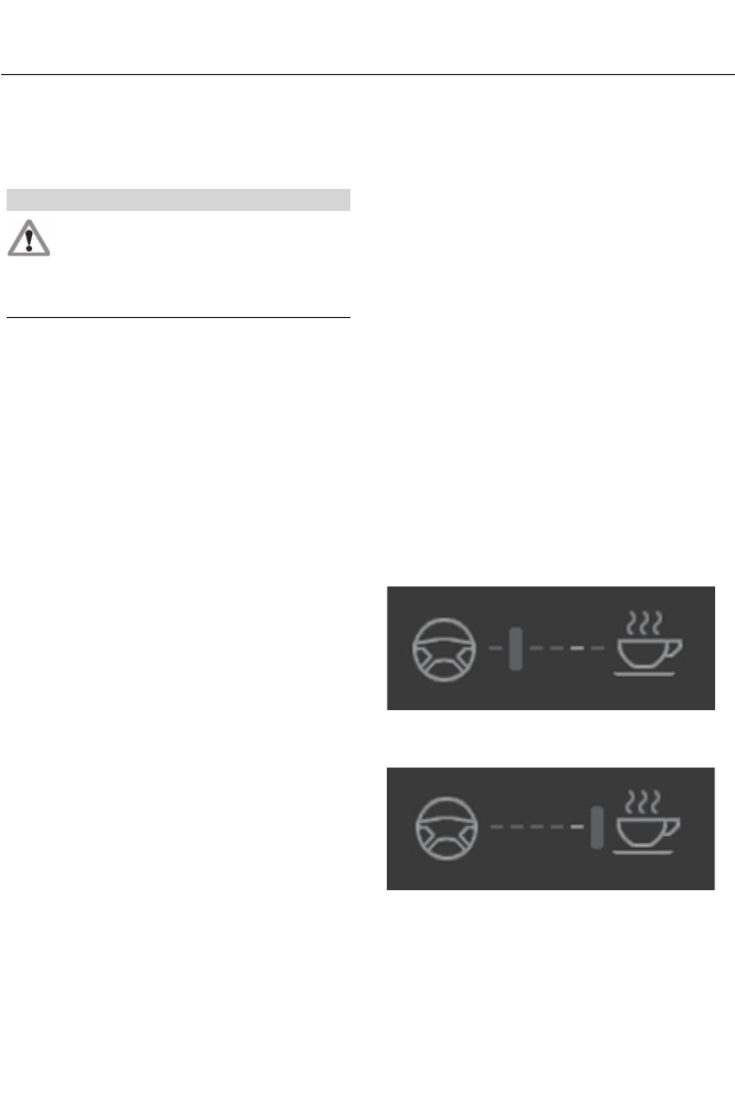
DRIVER ALERT (IF EQUIPPED)
PRINCIPLE OF OPERATION
WARNING
The driver alert system is designed
to aid you. It is not intended to
replace your attention and judgment.
You are still responsible to drive with due
care and attention.
Note: The system will store the on/off
setting in the information display menu
through ignition cycles.
Note: If enabled in the menu, the system
will be active at speeds above 40 mph (64
km/h).
Note: The system works as long as one lane
marking can be detected by the camera.
Note: If the camera is blocked or if the
windshield is damaged, the system may not
function.
Note: The system may not be available in
poor weather or other low visibility
conditions.
The system automatically monitors your
driving behavior using various inputs
including the front camera sensor.
If the system detects that your driving
alertness is reduced below a certain
threshold, the system will alert you using
a chime and a message in the cluster
display.
USING DRIVER ALERT
Switching the system on and off
By default, the system is enabled. You may
disable or re-enable the system by
selecting Setting then Driver Assist then
Driver Alert in the menu. When activated,
the system will monitor your alertness level
based upon your driving behavior in relation
to the lane markings, and other factors.
System Warnings
Note: Note: The system will not issue
warnings below approximately 40 mph (65
km/h).
The warning system is in two stages. At
first the system issues a temporary warning
that you need to take a rest. This message
will only appear for a short time. If the
system detects further reduction in driving
alertness, another warning may be issued
which will remain in the information display
for a longer time. Press OK on the steering
wheel control to clear the warning
System Display
When active the system will run
automatically in the background and only
issue a warning if required. You can view
the status at any time using the
information display. See General
Information (page 84).
The alertness level is shown by six steps
in a colored bar.
E131358
Alertness level is fine, no rest required.
E131359
Alertness level is critical, indicating that a
rest should be taken as soon as safely
possible.
188
Driving Aids

The status bar will travel from left to right
as the calculated alertness level
decreases. As the rest icon is approached
the color turns from green to yellow and
then finally red when a rest break should
be taken.
• Green - No rest required.
• Yellow - First (temporary) warning.
• Red - Second warning.
Note: If you have recently received a
warning; you should consider resting, even
if the current assessment is with the typical
range.
Note: The alertness level will be shown in
grey if the camera sensor cannot track the
road lane markings or if the vehicle speed
drops below approximately 40 mph (65
km/h).
Resetting the System
You can reset the system by either:
• Switching the ignition off and on.
• Stopping the vehicle and then opening
and closing the driver’s door.
LANE KEEPING SYSTEM (IF
EQUIPPED)
WARNING
The system is designed to aid the
driver. It is not intended to replace
the driver’s attention and judgment.
The driver is still responsible to drive with
due care and attention.
Note: The system needs to be activated by
the driver at each key cycle.
Note: The system works above 40 mph (64
km/h).
Note: The system works as long as one lane
marking can be detected by the camera.
Note: If the camera is blocked or if the
windshield is damaged, the system may not
function.
Note: When Aid mode is on and the system
detects no driver steering activity for a short
continuous period of time, the system alerts
the driver to put their hands on the steering
wheel. The system may detect a light
grip/touch on the steering wheel as hands
off driving.
The system detects unintentional drifting
toward the outside of the lane and alerts
and/or aids the driver to stay in the lane
through the steering system and
instrument cluster display. The system
automatically detects and tracks the road
lane markings using a camera that is
mounted behind the interior rear view
mirror.
Switching the System On and Off
Note: The system defaults to off each time
the vehicle is started, unless a MyKey® is
detected. If a MyKey® is detected, the
system is defaulted to on and the Alert
mode is automatically selected.
Note: If a MyKey® is detected, pressing the
button will not affect the on/off status of
the system. Only the Mode, Sensitivity and
Intensity settings can be changed when a
MyKey® is present.
To turn the system on, press the
button located on the left
steering wheel stalk. The button
must be pressed each time the vehicle is
started. The system can be turned off by
pressing the button again.
189
Driving Aids

System Settings
The system has three optional setting
menus available. To view or adjust them,
select Settings > Vehicle Settings > Driver
Assist > Lane Keeping Sys in the left-hand
instrument cluster display using the OK
button on the steering wheel. The
last-known selection for each of these
settings is stored by the system. You do
not need to readjust your settings each
time you turn on the system.
Mode: This setting allows the driver to
select which of the system features will be
enabled and turned on when the button is
pressed.
• Alert only – Provides a steering wheel
vibration when an unintended lane
departure is detected.
• Aid only – Provides a steering input
toward the lane center when an
unintended lane departure is detected.
• Both Alert + Aid
Intensity: This setting affects the intensity
of the steering wheel vibration used for the
alert and alert + aid modes. This setting
does not impact the aid mode.
•Low
• Medium
• High
System Display
E151660
When the system is turned on, an overhead
graphic of a vehicle with lane markings will
be displayed in the left-hand instrument
cluster display. If the aid mode is selected
when the system is turned on, a separate
white icon will also appear in the
instrument cluster.
When the system is turned off, the lane
marking graphics will not be displayed.
Note: The overhead vehicle graphic may
still be displayed if adaptive cruise control
is enabled.
While the system is on, the color of the
lane markings will change to indicate the
system status.
Gray: Indicates that the system is
temporarily unable to provide a warning
or intervention on the indicated side(s).
This may be because:
• the vehicle is under the activation
speed
• the turn indicator is active
• the vehicle is in a dynamic maneuver
• the road has no or poor lane markings
in the camera field-of-view
• the camera is obscured or unable to
detect the lane markings due to
environmental conditions (e.g.
significant sun angles or shadows,
snow, heavy rain, fog), traffic
conditions (e.g. following a large
vehicle that is blocking or shadowing
the lane), or vehicle conditions (e.g.
poor headlamp illumination).
See Troubleshooting for additional
information.
Green: Indicates that the system is
available or ready to provide a warning or
intervention, on the indicated side(s).
Yellow: Indicates that the system is
providing or has just provided a lane
keeping aid intervention.
190
Driving Aids

Red: Indicates that the system is providing
or has just provided a lane keeping alert
warning.
The system can be temporarily suppressed
at any time by the following:
• Quick braking
• Fast acceleration
• Using the turn signal indicator
• Evasive steering maneuver
Troubleshooting
Why is the feature not available (line markings are gray) when I can see the lane markings
on the road?
Vehicle speed is outside the operational range of the feature
Sun is shining directly into the camera lens
Quick intentional lane change
Staying too close to the lane marking
Driving at high speeds in curves
Previous feature activation happened within the last one second
Ambiguous lane markings (mainly in construction zones)
Rapid transition from light to dark or vice versa
Why is the feature not available (line markings are gray) when I can see the lane markings
on the road?
Sudden offset in lane markings
ABS or AdvanceTrac activation
Camera blockage due to dirt, grime, fog, frost or water on the windshield
Too close to the vehicle in front of you
Transitioning between no lane markings to lane markings or vice versa
Standing water on the road
Faint lane markings (partial yellow lane markings on concrete roads)
Lane width too narrow or too wide
Camera not calibrated after a windshield replacement
When driving on tight roads or on uneven roads
191
Driving Aids
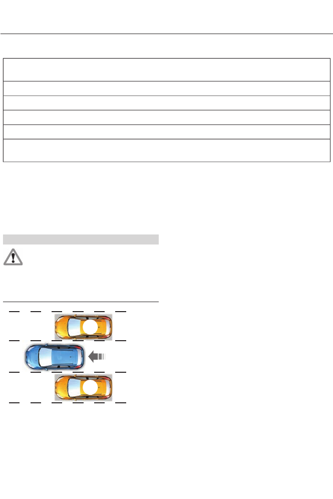
Why does the vehicle not come back into the middle of the lane always, as expected, in
the Aid or Aid + Alert mode?
High cross winds
Large road crown
Rough roads, grooves, shoulder drop-offs
Heavy uneven loading of the vehicle or improper tire inflation pressure
If the tires have been exchanged (including snow tires), or the suspension has been
modified
BLIND SPOT MONITOR
Blind Spot Information System
(BLIS®) with Cross Traffic Alert (If
Equipped)
WARNING
To help avoid injuries, NEVER use the
BLIS as a replacement for using the
interior and exterior mirrors and
looking over your shoulder before changing
lanes. BLIS is not a replacement for careful
driving and only an assist.
A
A
E124788
BLIS aids you in detecting vehicles that
may have entered the blind spot zone (A).
The detection area is on both sides of the
vehicle, extending rearward from the
exterior mirrors to approximately 10 feet
(3 meters) beyond the bumper. The
system alerts you if certain vehicles enter
the blind spot zone while driving.
Cross traffic alert warns you of vehicles
approaching from the sides when the
transmission is in R (Reverse).
Note: BLIS is not designed to prevent
contact with other vehicles or objects; or to
detect parked vehicles, people, animals or
infrastructure (fences, guardrails, trees,
etc.). It is designed to alert the driver to
vehicles in the blind zones.
Note: When a vehicle passes quickly
through the blind zone, typically fewer than
two seconds, the system does not trigger.
Using the Systems
BLIS turns on when the engine is started
and the vehicle is driven forward above 5
mph (8 km/h); it remains on while the
transmission is in D (Drive) and N
(Neutral). If shifted out of D (Drive) or N
(Neutral), the system enters cross traffic
alert mode. Once shifted back into D
(Drive), BLIS turns back on when the
vehicle is driven above 5 mph (8 km/h).
192
Driving Aids
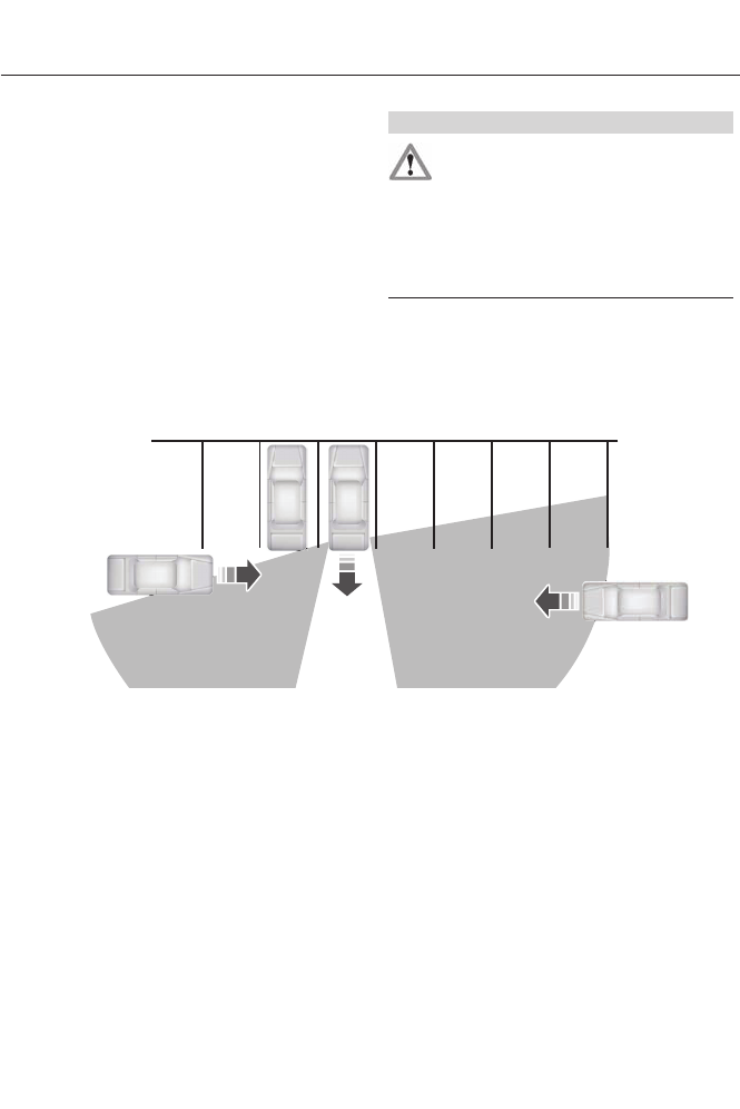
Note: BLIS does not function in R (Reverse)
or P (Park) or provide any additional
warning when a turn signal is on.
Note: Cross traffic alert detects
approaching vehicles from up to 45 feet (14
meters) away though coverage decreases
when the sensors are blocked. Reversing
slowly helps increase the coverage area and
effectiveness.
Note: For manual transmission vehicles,
CTA will be active only if the transmission
is in Reverse. If the vehicle is rolling
backwards and the transmission is not in
Reverse then CTA will not be active.
WARNING
To help avoid personal injury, NEVER
use the cross traffic alert system as
a replacement for using the interior
and exterior mirrors and looking over your
shoulder before backing out of a parking
space. Cross traffic alert is not a
replacement for careful driving and only
an assist.
E142440
In this first example, the left sensor is only
partially obstructed; zone coverage is
nearly maximized.
193
Driving Aids
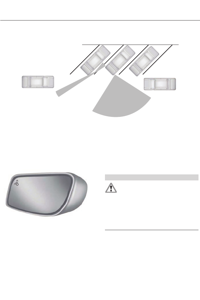
E142441
Zone coverage also decreases when
parking at shallow angles. Here, the left
sensor is mostly obstructed; zone coverage
on that side is severely limited.
System Lights and Messages
E142442
The BLIS and cross traffic alert systems
illuminate a yellow alert indicator in the
outside mirror on the side of the vehicle
the approaching vehicle is coming from.
Note: The alert indicator dims when
nighttime darkness is detected.
Cross traffic alert also sounds an audible
warning and a message appears in the
information display indicating a vehicle is
coming from the right or left. Cross traffic
alert works with the reverse sensing
system which sounds its own series of
tones. See Parking Aid (page 172).
System Sensors
WARNING
Just prior to the system recognizing
a blocked condition and alerting the
driver, the number of missed objects
will increase. To help avoid injuries, NEVER
use the BLIS as a replacement for using
the side and rear view mirrors and looking
over your shoulder before changing lanes.
BLIS is not a replacement for careful
driving and only an assist.
Note: It is possible to get a blockage
warning with no blockage present; this is
rare and known as a false blockage warning.
A false blocked condition either
self-corrects or clears after a key cycle.
194
Driving Aids
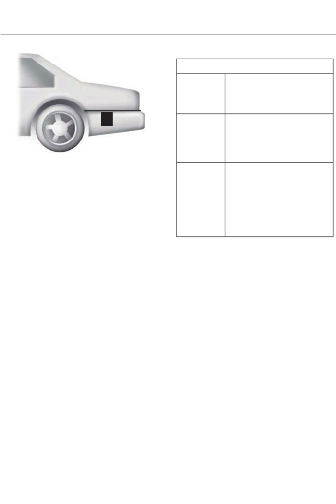
E142443
The system uses radar sensors which are
located behind the bumper fascia on each
side of your vehicle. Do not allow these
areas to become obstructed by mud, snow
or bumper stickers, as this can cause
degraded system performance.
If the system detects a degraded
performance condition, a message warning
of a blocked sensor or a message warning
of low visibility will appear in the
information display and the alert indicator
illuminates in the appropriate mirror(s).
The information display warning can be
cleared but the alert indicator remains
illuminated.
When the blockage is removed, the system
can be reset in two ways:
• when at least two objects are detected
while driving, or
• turn the ignition from on to off, then
back on.
If the blockage is still present after the key
cycle, the system senses again that it is
blocked after driving in traffic.
Reasons for messages being displayed
Clean the fascia area in
front of the radar or remove
the obstruction.
The radar
surface is
dirty or
obstructed
Drive normally in traffic for
a few minutes to allow the
radar to detect passing
vehicles so it can clear the
blocked state.
The radar
surface is
not dirty or
obstructed
No action required. The
system automatically
resets to an unblocked
state once the rainfall or
snowfall rate decreases or
stops. Do not use BLIS or
cross traffic alert in these
conditions.
Heavy rain-
fall/snow-
fall inter-
feres with
the radar
signals
System Limitations
The BLIS and cross traffic alert systems
do have their limitations; situations such
as severe weather conditions or debris
build-up on the sensor area may limit
vehicle detection.
The following are other situations that may
limit the BLIS:
• Certain maneuvering of vehicles
entering and exiting the blind zone.
• Vehicles passing through the blind zone
at very fast rates.
• When several vehicles forming a
convoy pass through the blind zone.
The following are other situations that may
limit the cross traffic alert system:
• Adjacently parked vehicles or objects
obstructing the sensors.
• Approaching vehicles passing at
speeds greater than 15 mph (24 km/h).
195
Driving Aids

• Driving in reverse faster than 5 mph (8
km/h).
• Backing out of an angled parking spot.
False Alerts
Note: If a trailer is connected to the vehicle
the BLIS system may detect the trailer
causing a false alert. You may want to turn
the BLIS off manually.
There may be certain instances when
either the BLIS or cross traffic alert
systems illuminate the alert indicator with
no vehicle in the coverage zone; this is
known as a false alert. Some amount of
false alerts are normal; they are temporary
and self-correct.
System Errors
If either system senses a problem with the
left or right sensor, the BLIS telltale will
illuminate and a message will appear in
the information display.
All other system faults will only be
displayed by a message in the information
display.
Switching the Systems Off and On
One or both systems can be switched off
temporarily by using the information
display control. See General Information
(page 84). When the BLIS is switched off,
you will not receive alerts and a telltale
illuminates in the information display.
Note: The CTA system always switches on
whenever the ignition is switched on.
However, the BLIS system will remember
the last selected on or off setting.
One or both systems cannot be switched
off when MyKey is used. See Principle of
Operation (page 48).
One or both systems can also be switched
off permanently at your authorized dealer.
Once switched off, switching it back on
must also be done at your authorized
dealer.
STEERING
Electric Power Steering
WARNING
Obtain immediate service if a system
error is detected. You may not notice
any difference in the feel of your
steering, but a serious condition may exist.
Failure to do so may result in loss of
steering control.
Note: Your vehicle is equipped with an
electric power-assisted steering system.
There is no fluid reservoir to check or fill.
The electric power steering system has
diagnostic checks that continuously
monitor the system to ensure proper
operation of the electronic system. When
an electronic error is detected, a message
will be displayed in the information display.
If this happens, stop the vehicle in a safe
place, and turn off the engine. After at least
10 seconds, reset the system by restarting
the engine, and watch the information
display for a steering message. If a steering
message returns, or returns while driving,
take the vehicle to your dealer to have it
checked.
If your vehicle loses electrical power while
you are driving (or if the ignition is turned
off), you can steer the vehicle manually,
but it takes more effort. Extreme
continuous steering may increase the effort
it takes for you to steer. This occurs to
prevent internal overheating and
permanent damage to your steering
196
Driving Aids
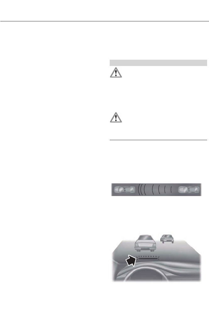
system. If this should occur, you will neither
lose the ability to steer the vehicle
manually nor will it cause permanent
damage. Typical steering and driving
maneuvers will allow the system to cool
and steering assist will return to normal.
Steering Tips
If the steering wanders or pulls, check for:
• an improperly inflated tire
• uneven tire wear
• loose or worn suspension components
• loose or worn steering components
• improper vehicle alignment
A high crown in the road or high crosswinds
may also make the steering seem to
wander or pull.
Adaptive Learning
The EPS system adaptive learning helps
correct for road irregularities and improves
overall handling and steering feel. It
communicates with the vehicle's brake
system to help operate advanced stability
control and accident avoidance systems.
Additionally, whenever the battery is
disconnected or a new battery installed,
the vehicle must be driven a short distance
before the strategy is relearned and all
systems are reactivated.
COLLISION WARNING SYSTEM
PRINCIPLE OF OPERATION (If
Equipped)
WARNINGS
This system is designed to be a
supplementary driving aid. It is not
intended to replace the driver’s
attention, and judgment, or the need to
apply the brakes. This system does NOT
activate the brakes automatically. Failure
to press the brake pedal to activate the
brakes may result in a collision.
The collision warning system with
brake support cannot help prevent
all collisions. Do not rely on this
system to replace driver judgment and the
need to maintain distance and speed.
Note: The system does not detect, warn or
respond to potential collisions with vehicles
to the rear or sides of the vehicle.
Note: The collision warning system is active
at speeds above approximately 5 mph (8
km/h).
E156130
This system is designed to alert the driver
of certain collision risks. A radar detects if
your vehicle is rapidly approaching another
vehicle traveling in the same direction as
yours.
E156131
197
Driving Aids
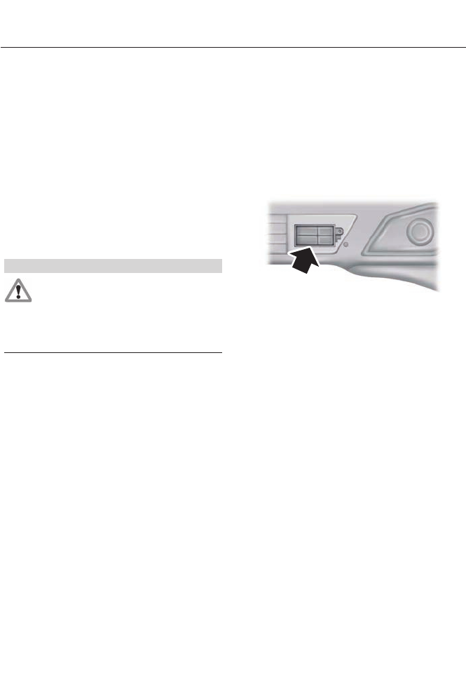
If it is, a red warning light illuminates and
an audible warning chime sounds.
The brake support system assists the driver
in reducing the collision speed by charging
the brakes. If the risk of collision further
increases after the warning light
illuminates, the brake support prepares
the brake system for rapid braking. This
may be apparent to the driver. The system
does not automatically activate the brakes
but, if the brake pedal is pressed, full force
braking is applied even if the brake pedal
is lightly pressed.
Using the Collision Warning System
WARNING
The collision warning system’s brake
support can only help reduce the
speed at which a collision occurs if
the driver applies the vehicle’s brakes. The
brake pedal must be pressed just like any
typical braking situation.
The warning system sensitivity can be
adjusted to one of three possible settings
by using the information display control.
See General Information (page 84).
Note: If the system cannot be turned off in
a vehicle equipped with MyKey®, See
Principle of Operation (page 48).
Note: If collision warnings are perceived as
being too frequent or disturbing then the
warning sensitivity can be reduced, though
the manufacturer recommends using the
highest sensitivity setting where possible.
Setting lower sensitivity would lead to fewer
and later system warnings. See General
Information (page 84).
Blocked Sensors
E145632
If a message regarding a blocked sensor
appears in the information display, the
radar signals from the sensor have been
obstructed. The sensors are located behind
a fascia cover near the driver side of the
lower grille. When the sensors are
obstructed, a vehicle ahead cannot be
detected and the collision warning system
does not function. The following table lists
possible causes and actions for this
message being displayed.
198
Driving Aids
ActionCause
Clean the grille surface in front of the radar
or remove the object causing the obstruc-
tion
The surface of the radar in the grille is dirty
or obstructed in some way
Wait a short time. It may take several
minutes for the radar to detect that it is no
longer obstructed
The surface of the radar in the grille is clean
but the message remains in the display
The collision warning system is temporarily
disabled. Collision warning should automat-
ically reactivate a short time after the
weather conditions improve
Heavy rain, spray, snow, or fog is interfering
with the radar signals
The collision warning system is temporarily
disabled. Collision warning should automat-
ically reactivate a short time after the
weather conditions improve
Swirling water, or snow or ice on the surface
of the road may interfere with the radar
signals
System Limitations
WARNING
The collision warning system’s brake
support can only help reduce the
speed at which a collision occurs if
the driver applies the vehicle’s brakes. The
brake pedal must be pressed just like any
typical braking situation.
Due to the nature of radar technology,
there may be certain instances where
vehicles do not provide a collision warning.
These include:
• Stationary vehicles or vehicles moving
below 6 mph (10 km/h).
• Pedestrians or objects in the roadway.
• Oncoming vehicles in the same lane.
• Severe weather conditions (see
blocked sensor section).
• Debris build-up on the grille near the
headlamps (see blocked sensor
section).
• Small distance to vehicle ahead.
• Steering wheel and pedal movements
are large (very active driving style).
•
If the front end of the vehicle is hit or
damaged, the radar sensing zone may be
altered causing missed or false collision
warnings. See your authorized dealer to
have your collision warning radar checked
for proper coverage and operation.
199
Driving Aids
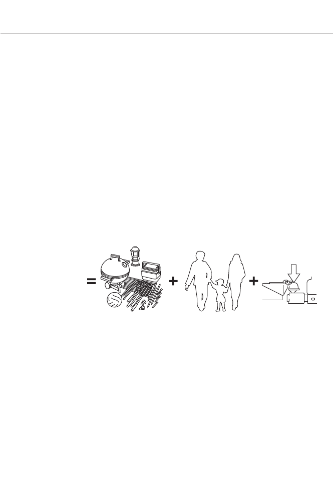
LOAD LIMIT
Vehicle Loading - with and without
a Trailer
This section will guide you in the
proper loading of your vehicle,
trailer or both, to keep your loaded
vehicle weight within its design
rating capability, with or without
a trailer. Properly loading your
vehicle will provide maximum
return of vehicle design
performance. Before loading your
vehicle, familiarize yourself with
the following terms for
determining your vehicle’s weight
ratings, with or without a trailer,
from the vehicle’s Tire Label or
Safety Compliance Certification
Label:
Base Curb Weight - is the weight
of the vehicle including a full tank
of fuel and all standard
equipment. It does not include
passengers, cargo, or optional
equipment.
Vehicle Curb Weight - is the
weight of your new vehicle when
you picked it up from your
authorized dealer plus any
aftermarket equipment.
E143816
PAYLOAD
Payload - is the combined weight
of cargo and passengers that the
vehicle is carrying. The maximum
payload for your vehicle can be
found on the Tire Label on the
B-Pillar or the edge of the driver
door (vehicles exported outside
the US and Canada may not have
a Tire Label). Look for “THE
COMBINED WEIGHT OF
OCCUPANTS AND CARGO
SHOULD NEVER EXCEED XXX
kg OR XXX lb.” for maximum
payload. The payload listed on the
Tire Label is the maximum
payload for the vehicle as built by
the assembly plant. If you install
any aftermarket or
200
Load Carrying
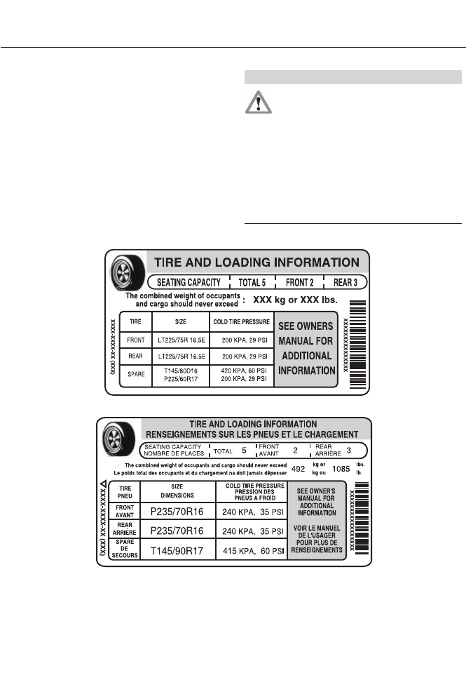
authorized-dealer installed
equipment on the vehicle, you
must subtract the weight of the
equipment from the payload listed
on the Tire Label in order to
determine the new payload.
WARNING
The appropriate loading capacity of
your vehicle can be limited either by
volume capacity (how much space
is available) or by payload capacity (how
much weight the vehicle should carry).
Once you have reached the maximum
payload of your vehicle, do not add more
cargo, even if there is space available.
Overloading or improperly loading your
vehicle can contribute to loss of vehicle
control and vehicle rollover.
Example only:
E142516
E142517
201
Load Carrying
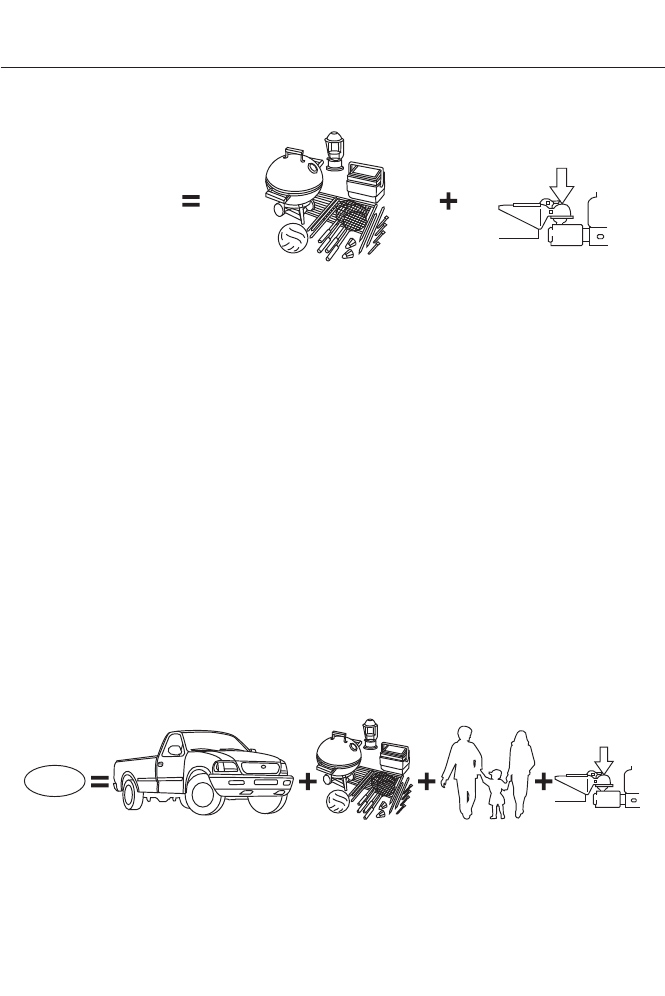
E143817
CARGO
Cargo Weight - includes all
weight added to the Base Curb
Weight, including cargo and
optional equipment. When towing,
trailer tongue load or king pin
weight is also part of cargo weight.
GAW (Gross Axle Weight) - is
the total weight placed on each
axle (front and rear) including
vehicle curb weight and all
payload.
GAWR (Gross Axle Weight
Rating) - is the maximum
allowable weight that can be
carried by a single axle (front or
rear). These numbers are shown
on the Safety Compliance
Certification Label. The label shall
be affixed to either the door hinge
pillar, door-latch post, or the door
edge that meets the door-latch
post, next to the driver's seating
position. The total load on each
axle must never exceed its
Gross Axle Weight Rating.
Note: For trailer towing information refer
to the RV and Trailer Towing Guide available
at an authorized dealer.
E143818
GVW
202
Load Carrying
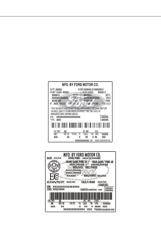
GVW (Gross Vehicle Weight) -
is the Vehicle Curb Weight, plus
cargo, plus passengers.
GVWR (Gross Vehicle Weight
Rating) - is the maximum
allowable weight of the fully
loaded vehicle (including all
options, equipment, passengers
and cargo). It is shown on the
Safety Compliance Certification
Label. The label shall be affixed
to either the door hinge pillar,
door-latch post, or the door edge
that meets the door-latch post,
next to the driver's seating
position. The Gross Vehicle
Weight must never exceed the
Gross Vehicle Weight Rating.
Example only:
E142523
E142524
203
Load Carrying
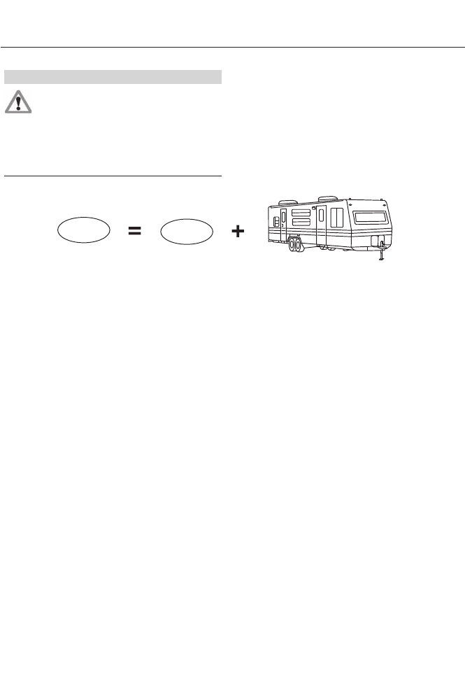
WARNING
Exceeding the Safety Compliance
Certification Label vehicle weight
rating limits could result in
substandard vehicle handling or
performance, engine, transmission and/or
structural damage, serious damage to the
vehicle, loss of control and personal injury.
E143819
GCW GVW
GCW (Gross Combined Weight)
- is the Gross Vehicle Weight plus
the weight of the fully loaded
trailer.
GCWR (Gross Combined
Weight Rating) - is the maximum
allowable weight of the vehicle
and the loaded trailer, including
all cargo and passengers, that the
vehicle can handle without risking
damage. (Important: The towing
vehicle’s braking system is rated
for operation at Gross Vehicle
Weight Rating, not at Gross
Combined Weight Rating.)
Separate functional brakes should
be used for safe control of towed
vehicles and for trailers where the
Gross Combined Weight of the
towing vehicle plus the trailer
exceed the Gross Vehicle Weight
Rating of the towing vehicle. The
Gross Combined Weight must
never exceed the Gross
Combined Weight Rating.
Maximum Loaded Trailer
Weight - is the highest possible
weight of a fully loaded trailer the
vehicle can tow. It assumes a
vehicle with mandatory options,
driver and front passenger weight
(150 pounds [68 kilograms]
each), no cargo weight (internal
or external) and a tongue load of
10–15% (conventional trailer) or
king pin weight of 15–25% (fifth
wheel trailer). Consult an
authorized dealer (or the RV and
Trailer Towing Guide available at
an authorized dealer) for more
detailed information.
204
Load Carrying
Tongue Load or Fifth Wheel
King Pin Weight - refers to the
amount of the weight that a trailer
pushes down on a trailer hitch.
Examples: For a 5000 pound
(2268 kilogram) conventional
trailer, multiply 5000 by 0.10 and
0.15 to obtain a proper tongue
load range of 500 to 750 pounds
(227 to 340 kilograms). For an
11500 pound (5216 kilogram) fifth
wheel trailer, multiply by 0.15 and
0.25 to obtain a proper king pin
load range of 1725 to 2875 pounds
(782 to 1304 kilograms).
WARNINGS
Do not exceed the GVWR or the
GAWR specified on the Safety
Compliance Certification Label.
Do not use replacement tires with
lower load carrying capacities than
the original tires because they may
lower the vehicle’s GVWR and GAWR
limitations. Replacement tires with a higher
limit than the original tires do not increase
the GVWR and GAWR limitations.
Exceeding any vehicle weight rating
limitation could result in serious
damage to the vehicle and/or
personal injury.
Steps for determining the
correct load limit:
1. Locate the statement "The
combined weight of occupants
and cargo should never exceed
XXX kg or XXX lb." on your
vehicle’s placard.
2. Determine the combined weight
of the driver and passengers that
will be riding in your vehicle.
3. Subtract the combined weight
of the driver and passengers from
XXX kg or XXX lb.
4. The resulting figure equals the
available amount of cargo and
luggage load capacity. For
example, if the “XXX” amount
equals 1,400 lb. and there will be
five 150 lb. passengers in your
vehicle, the amount of available
cargo and luggage load capacity
is 650 lb. (1400-750 (5 x 150) =
650 lb.)
5. Determine the combined weight
of luggage and cargo being loaded
on the vehicle. That weight may
not safely exceed the available
cargo and luggage load capacity
calculated in Step 4.
6. If your vehicle will be towing a
trailer, load from your trailer will
be transferred to your vehicle.
Consult this manual to determine
how this reduces the available
cargo and luggage load capacity
of your vehicle.
The following gives you a few
examples on how to calculate the
available amount of cargo and
luggage load capacity:
205
Load Carrying

*Suppose your vehicle has a
1400-pound (635-kilogram) cargo
and luggage capacity. You decide
to go golfing. Is there enough load
capacity to carry you, four of your
friends and all the golf bags? You
and four friends average 220
pounds (99 kilograms) each and
the golf bags weigh approximately
30 pounds (13.5 kilograms) each.
The calculation would be: 1400 -
(5 x 220) - (5 x 30) = 1400 - 1100
- 150 = 150 pounds. Yes, you have
enough load capacity in your
vehicle to transport four friends
and your golf bags. In metric units,
the calculation would be: 635
kilograms - (5 x 99 kilograms) -
(5 x 13.5 kilograms) = 635 - 495 -
67.5 = 72.5 kilograms.
*Suppose your vehicle has a
1400-pound (635-kilogram) cargo
and luggage capacity. You and
one of your friends decide to pick
up cement from the local home
improvement store to finish that
patio you have been planning for
the past two years. Measuring the
inside of the vehicle with the rear
seat folded down, you have room
for twelve 100-pound
(45-kilogram) bags of cement. Do
you have enough load capacity to
transport the cement to your
home? If you and your friend each
weigh 220 pounds (99 kilograms),
the calculation would be: 1400 -
(2 x 220) - (12 x 100) = 1400 - 440
- 1200 = - 240 pounds. No, you do
not have enough cargo capacity
to carry that much weight. In
metric units, the calculation would
be: 635 kilograms - (2 x 99
kilograms) - (12 x 45 kilograms) =
635 - 198 - 540 = -103 kilograms.
You will need to reduce the load
weight by at least 240 pounds
(104 kilograms). If you remove
three 100-pound (45-kilogram)
cement bags, then the load
calculation would be: 1400 - (2 x
220) - (9 x 100) = 1400 - 440 -
900 = 60 pounds. Now you have
the load capacity to transport the
cement and your friend home. In
metric units, the calculation would
be: 635 kilograms - (2 x 99
kilograms) - (9 x 45 kilograms) =
635 - 198 - 405 = 32 kilograms.
The above calculations also
assume that the loads are
positioned in your vehicle in a
manner that does not overload
the Front or the Rear Gross Axle
Weight Rating specified for your
vehicle on the Safety Compliance
Certification Label. The label shall
be affixed to either the door hinge
pillar, door-latch post, or the door
edge that meets the door-latch
post, next to the driver's seating
position.
206
Load Carrying
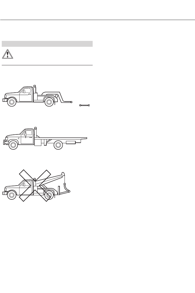
TOWING A TRAILER
WARNING
Never tow a trailer with a Fusion
Hybrid. This powertrain is not
designed to tow.
TRANSPORTING THE VEHICLE
E143886
If you need to have your vehicle towed,
contact a professional towing service or,
if you are a member of a roadside
assistance program, your roadside
assistance service provider.
We recommend the use of a wheel lift and
dollies or flatbed equipment to tow your
vehicle. Do not tow with a slingbelt. Ford
Motor Company has not approved a
slingbelt towing procedure. Vehicle
damage may occur if towed incorrectly, or
by any other means.
Ford Motor Company produces a towing
manual for all authorized tow truck
operators. Have your tow truck operator
refer to this manual for proper hook-up
and towing procedures for your vehicle.
The front wheels (drive wheels) must be
on a tow dolly when towing your vehicle
from the rear using wheel lift equipment.
This prevents damage to the transmission.
We recommend placing the rear wheels
on a tow dolly when towing your vehicle
from the front using wheel lift equipment.
This prevents damage to the rear fascia.
TOWING THE VEHICLE ON
FOUR WHEELS
Emergency Towing
If your vehicle becomes inoperable
(without access to wheel dollies,
car-hauling trailer, or flatbed transport
vehicle), it can be flat-towed (all wheels
on the ground, regardless of the powertrain
and transmission configuration) under the
following conditions:
• Tow only in the forward direction.
• The transmission in position N. If you
cannot move the transmission into N,
you may need to override it. See
Automatic Transmission (page 162).
• Maximum speed is 35 mph (56 km/h).
• Maximum distance is 50 miles (80
kilometers).
Recreational Towing
Note: Put your climate control system in
recirculated air mode to prevent exhaust
fumes from entering the vehicle. See
Climate Control (page ?).
207
Towing

Follow these guidelines if you have a need
for recreational (RV) towing. An example
of recreational towing would be towing
your vehicle behind a motorhome. We
designed these guidelines to prevent
damage to your transmission
You can tow your vehicle with all four
wheels on the ground or with the front
wheels off the ground by using a tow dolly.
If you are using a tow dolly, follow the
instructions specified by the equipment
provider.
If you tow your vehicle with all four wheels
on the ground:
• Tow only in the forward direction.
• Release the parking brake.
• Place the transmission in position N.
• Place the ignition in the accessory
position. See Starting and Stopping
the Engine (page 132).
• Do not exceed 70 mph (113 km/h).
• Place the transmission in position P,
start the vehicle and allow it to run for
one minute at the beginning of each
day (you may need to press the
accelerator pedal in order to start the
vehicle). After allowing the vehicle to
run, place the transmission back into
position N and the ignition in the
accessory position.
208
Towing

BREAKING-IN
You need to break in new tires for
approximately 300 miles (480
kilometers). During this time, your vehicle
may exhibit some unusual driving
characteristics. The engine also needs to
break in. Avoid hard accelerations and
driving too fast for the first 1000 miles
(1600 kilometers). If possible, avoid
carrying heavy loads up steep grades
during the break-in period.
ECONOMICAL DRIVING
Fuel economy is affected by several things
such as how you drive, the conditions you
drive under and how you maintain your
vehicle.
There are some things to keep in mind that
may improve your fuel economy:
• Accelerate and slow down in a smooth,
moderate fashion.
• Drive at steady speeds.
• Anticipate stops; slowing down may
eliminate the need to stop.
• Combine errands and minimize
stop-and-go driving.
• When running errands, go to the
furthest destination first and then
work your way back home.
• Close the windows for high-speed
driving.
• Drive at reasonable speeds. (Traveling
at 65 mph/105 kph uses about 15%
less fuel than traveling at 75 mph/121
kph).
• Keep the tires properly inflated and use
only the recommended size.
• Use the recommended engine oil.
• Perform all regularly scheduled
maintenance.
There are also some things you may want
to avoid doing because they reduce your
fuel economy:
• Avoid sudden or hard accelerations.
• Avoid revving the engine before turning
off the car.
• Avoid long idle periods.
• Do not warm up your vehicle on cold
mornings.
• Reduce the use of air conditioning and
heat.
• Avoid using speed control in hilly
terrain.
• Do not rest your foot on the brake
pedal while driving.
• Avoid carrying unnecessary weight
(approximately 1 mpg [0.4
kilometers/liter] is lost for every 400
lbs [180 kilograms] of weight carried).
• Avoid adding particular accessories to
your vehicle (e.g. bug deflectors,
rollbars/light bars, running boards, ski
racks).
• Avoid driving with the wheels out of
alignment.
DRIVING THROUGH WATER
Note: Driving through deep water above
the recommended levels can cause vehicle
damage.
If driving through deep or standing water
is unavoidable, proceed very slowly. Never
drive through water that is higher than the
bottom of the wheel rims (for cars) or the
bottom of the hubs (for trucks).
209
Driving Hints
E142667
When driving through water, traction or
brake capability may be limited. Also,
water may enter your engine’s air intake
and severely damage your engine or your
vehicle may stall.
Once through the water, always dry the
brakes by moving your vehicle slowly while
applying light pressure on the brake pedal.
Wet brakes do not stop the vehicle as
quickly as dry brakes.
FLOOR MATS
E142666
WARNINGS
Always use floor mats that are
designed to fit the foot well of your
vehicle. Only use floor mats that
leave the pedal area unobstructed. Only
use floor mats that are firmly secured to
retention posts so that they cannot slip out
of position and interfere with the pedals
or impair safe operation of your vehicle in
other ways.
Pedals that cannot move freely can
cause loss of vehicle control and
increase the risk of serious personal
injury.
Always make sure that the floor
mats are properly attached to the
retention posts in the carpet that are
supplied with your vehicle. Floor mats must
be properly secured to both retention posts
to ensure mats do not shift out of position.
Never place floor mats or any other
covering in the vehicle foot well that
cannot be properly secured to
prevent them from moving and interfering
with the pedals or the ability to control the
vehicle.
Never place floor mats or any other
covering on top of already installed
floor mats. Floor mats should always
rest on top of vehicle carpeting surface and
not another floor mat or other covering.
Additional floor mats or any other covering
will reduce the pedal clearance and
potentially interfere with pedal operation.
Check attachment of floor mats on
a regular basis. Always properly
reinstall and secure floor mats that
have been removed for cleaning or
replacement.
Always make sure that objects
cannot fall into the driver foot well
while the vehicle is moving. Objects
that are loose can become trapped under
the pedals causing a loss of vehicle control.
210
Driving Hints

WARNINGS
Failure to properly follow floor mat
installation or attachment
instructions can potentially cause
interference with pedal operation causing
loss of control of vehicle.
To install floor mats, position the
floor mat so that the eyelet is over
the retention post and press down
to lock in.
To remove the floor mat, reverse the
installation procedure.
211
Driving Hints

GETTING THE SERVICES YOU
NEED
Warranty repairs to your vehicle must be
performed by an authorized dealer. While
any authorized dealer handling your vehicle
line will provide warranty service, we
recommend you return to your selling
authorized dealer who wants to ensure
your continued satisfaction.
Please note that certain warranty repairs
require special training and equipment, so
not all authorized dealers are authorized
to perform all warranty repairs. This means
that, depending on the warranty repair
needed, you may have to take your vehicle
to another authorized dealer.
A reasonable time must be allowed to
perform a repair after taking your vehicle
to the authorized dealer. Repairs will be
made using Ford or Motorcraft® parts, or
remanufactured or other parts that are
authorized by Ford.
Away From Home
If you are away from home when your
vehicle needs service, contact the Ford
Customer Relationship Center or use the
online resources listed below to find the
nearest authorized dealer.
In the United States:
Mailing address
Ford Motor Company
Customer Relationship Center
P.O. Box 6248
Dearborn, MI 48121
Telephone
1-800-392-3673 (FORD)
(TDD for the hearing impaired:
1-800-232-5952)
Online
Additional information and resources are
available online at www.fordowner.com
These are some of the items that can be
found online:
• U.S. dealer locator by Dealer Name,
City/State, or Zip Code
• Owner Manuals
• Maintenance Schedules
• Recalls
• Ford Extended Service Plans
• Ford Genuine Accessories
• Service specials and promotions.
In Canada:
Mailing address
Customer Relationship Centre
Ford Motor Company of Canada, Limited
P.O. Box 2000
Oakville, Ontario L6K 0C8
Telephone
1-800-565-3673 (FORD)
Online
www.ford.ca
Additional Assistance
If you have questions or concerns, or are
unsatisfied with the service you are
receiving, follow these steps:
1. Contact your Sales Representative or
Service Advisor at your selling/servicing
authorized dealer.
2. If your inquiry or concern remains
unresolved, contact the Sales Manager,
Service Manager or Customer Relations
Manager.
3. If you require assistance or clarification
on Ford Motor Company policies,
please contact the Ford Customer
Relationship Center.
212
Customer Assistance

In order to help you serve you better,
please have the following information
available when contacting a Customer
Relationship Center:
• Vehicle Identification Number.
• Your telephone number (home and
business).
• The name of the authorized dealer and
city where located.
• The vehicle’s current odometer reading.
In some states, you must directly notify
Ford in writing before pursuing remedies
under your state’s warranty laws. Ford is
also allowed a final repair attempt in some
states.
In the United States, a warranty dispute
must be submitted to the BBB AUTO LINE
before taking action under the
Magnuson-Moss Warranty Act, or to the
extent allowed by state law, before
pursuing replacement or repurchase
remedies provided by certain state laws.
This dispute handling procedure is not
required prior to enforcing state created
rights or other rights which are independent
of the Magnuson-Moss Warranty Act or
state replacement or repurchase laws.
IN CALIFORNIA (U.S. ONLY)
California Civil Code Section 1793.2(d)
requires that, if a manufacturer or its
representative is unable to repair a motor
vehicle to conform to the vehicle’s
applicable express warranty after a
reasonable number of attempts, the
manufacturer shall be required to either
replace the vehicle with one substantially
identical or repurchase the vehicle and
reimburse the buyer in an amount equal to
the actual price paid or payable by the
consumer (less a reasonable allowance
for consumer use). The consumer has the
right to choose whether to receive a refund
or replacement vehicle.
California Civil Code Section 1793.22(b)
presumes that the manufacturer has had
a reasonable number of attempts to
conform the vehicle to its applicable
express warranties if, within the first 18
months of ownership of a new vehicle or
the first 18000 miles (29 000 km),
whichever occurs first:
1. Two or more repair attempts are made
on the same non-conformity likely to
cause death or serious bodily injury OR
2. Four or more repair attempts are made
on the same nonconformity (a defect
or condition that substantially impairs
the use, value or safety of the vehicle)
OR
3. The vehicle is out of service for repair
of nonconformities for a total of more
than 30 calendar days (not necessarily
all at one time).
In the case of 1 or 2 above, the consumer
must also notify the manufacturer of the
need for the repair of the nonconformity
at the following address:
Ford Motor Company
16800 Executive Plaza Drive
Mail Drop 3NE-B
Dearborn, MI 48126
You are required to submit your warranty
dispute to BBB AUTO LINE before asserting
in court any rights or remedies conferred
by California Civil Code Section 1793.22(b).
You are also required to use BBB AUTO
LINE before exercising rights or seeking
remedies created by the Federal
Magnuson-Moss Warranty Act, 15 U.S.C.
sec. 2301 et seq. If you choose to seek
redress by pursuing rights and remedies
not created by California Civil Code Section
1793.22(b) or the Magnuson-Moss
Warranty Act, resort to BBB AUTO LINE is
not required by those statutes.
213
Customer Assistance

THE BETTER BUSINESS
BUREAU (BBB) AUTO LINE
PROGRAM (U.S. ONLY)
Your satisfaction is important to Ford
Motor Company and to your dealer. If a
warranty concern has not been resolved
using the three-step procedure outlined
earlier in this chapter in the Getting the
Services you need section, you may be
eligible to participate in the BBB AUTO
LINE program.
The BBB AUTO LINE program consists of
two parts – mediation and arbitration.
During mediation, a representative of the
BBB will contact both you and Ford Motor
Company to explore options for settlement
of the claim. If an agreement is not reached
during mediation or you do not want to
participate in mediation, and if your claim
is eligible, you may participate in the
arbitration process. An arbitration hearing
will be scheduled so that you can present
your case in an informal setting before an
impartial person. The arbitrator will
consider the testimony provided and make
a decision after the hearing.
Disputes submitted to the BBB AUTO LINE
program are usually decided within forty
days after you file your claim with the BBB.
You are not bound by the decision, and
may reject the decision and proceed to
court where all findings of the BBB Auto
Line dispute, and decision, are admissible
in the court action. Should you choose to
accept the BBB AUTO LINE decision, Ford
is then bound by the decision, and must
comply with the decision within 30 days
of receipt of your acceptance letter.
BBB AUTO LINE Application: Using the
information provided below, please call or
write to request a program application.
You will be asked for your name and
address, general information about your
new vehicle, information about your
warranty concerns, and any steps you have
already taken to try to resolve them. A
Customer Claim Form will be mailed that
will need to be completed, signed and
returned to the BBB along with proof of
ownership. Upon receipt, the BBB will
review the claim for eligibility under the
Program Summary Guidelines.
You can get more information by
calling BBB AUTO LINE at
1-800-955-5100, or writing to:
BBB AUTO LINE
4200 Wilson Boulevard, Suite 800
Arlington, Virginia 22203-1833
BBB AUTO LINE applications can also be
requested by calling the Ford Motor
Company Customer Relationship Center
at 1-800-392-3673.
Note: Ford Motor Company reserves the
right to change eligibility limitations, modify
procedures, or to discontinue this process
at any time without notice and without
obligation.
UTILIZING THE
MEDIATION/ARBITRATION
PROGRAM (CANADA ONLY)
For vehicles delivered to authorized
Canadian dealers. In those cases where
you continue to feel that the efforts by Ford
of Canada and the authorized dealer to
resolve a factory-related vehicle service
concern have been unsatisfactory, Ford of
Canada participates in an impartial third
party mediation/arbitration program
administered by the Canadian Motor
Vehicle Arbitration Plan (CAMVAP).
The CAMVAP program is a straight forward
and relatively speedy alternative to resolve
a disagreement when all other efforts to
produce a settlement have failed. This
procedure is without cost to you and is
designed to eliminate the need for lengthy
and expensive legal proceedings.
214
Customer Assistance

In the CAMVAP program, impartial
third-party arbitrators conduct hearings at
mutually convenient times and places in
an informal environment. These impartial
arbitrators review the positions of the
parties, make decisions and, when
appropriate, render awards to resolve
disputes. CAMVAP decisions are fast, fair,
and final as the arbitrator’s award is
binding on both you and Ford of Canada.
CAMVAP services are available in all
Canadian territories and provinces. For
more information, without charge or
obligation, call your CAMVAP Provincial
Administrator directly at 1-800-207-0685
or visit www.camvap.ca.
GETTING ASSISTANCE
OUTSIDE THE U.S. AND
CANADA
Before exporting your vehicle to a foreign
country, contact the appropriate foreign
embassy or consulate. These officials can
inform you of local vehicle registration
regulations and where to find unleaded
fuel.
If you cannot find unleaded fuel or can only
get fuel with an anti-knock index lower
than is recommended for your vehicle,
contact our Customer Relationship Center.
The use of leaded fuel in your vehicle
without proper conversion may damage
the effectiveness of your emission control
system and may cause engine knocking or
serious engine damage. Ford Motor
Company or Ford of Canada is not
responsible for any damage caused by use
of improper fuel. Using leaded fuel may
also result in difficulty importing your
vehicle back into the United States.
If your vehicle must be serviced while you
are traveling or living in Asia-Pacific Region,
Sub-Saharan Africa, U.S. Virgin Islands,
Central America, the Caribbean, and Israel,
contact the nearest authorized dealer. If
the authorized dealer cannot help you,
contact:
FORD MOTOR COMPANY
FORD EXPORT OPERATIONS & GLOBAL
INITIATIVES
Customer Relationship Center
1555 Fairlane Drive
Fairlane Business Park #3
Allen Park, Michigan 48101
U.S.A.
Telephone: (313) 594-4857
Fax: (313) 390-0804
Email: expcac@ford.com
For customers in Guam, the
Commonwealth of the Northern Mariana
Islands (CNMI), America Samoa, and the
U.S. Virgin Islands, please feel free to call
our Toll-Free Number: (800) 841-FORD
(3673).
If your vehicle must be serviced while you
are traveling or living in Puerto Rico,
contact the nearest authorized dealer. If
the authorized dealer cannot help you,
contact:
FORD MOTOR COMPANY
FORD EXPORT OPERATIONS & GLOBAL
INITIATIVES
Customer Relationship Center
1555 Fairlane Drive
Fairlane Business Park #3
Allen Park, Michigan 48101
U.S.A.
Telephone: (800) 841-FORD (3673)
FAX: (313) 390-0804
Email: prcac@ford.com
www.ford.com.pr
If your vehicle must be serviced while you
are traveling or living in the Middle East,
contact the nearest authorized dealer. If
the authorized dealer cannot help you,
contact:
215
Customer Assistance

Ford Middle East
Customer Relationship Center
P.O. Box 21470
Dubai, United Arab Emirates
Telephone: +971 4 3326084
Toll-Free Number for the Kingdom of Saudi
Arabia: 800 8971409
Local Telephone Number of Kuwait:
24810575
FAX: +971 4 3327299
Email: menacac@ford.com
www.me.ford.com
If you buy your vehicle in North America
and then relocate to any of the above
locations, register your vehicle
identification number (VIN) and new
address with Ford Motor Company Export
Operations & Global Growth Initiatives by
emailing expcac@ford.com.
If you are in another foreign country,
contact the nearest authorized dealer. In
the event your inquiry is unresolved,
communicate your concern with the
dealership’s Sales Manager, Service
Manager or Customer Relations Manager.
If you require additional assistance or
clarification, please contact the respective
Customer Relationship Center as
previously listed.
Customers in the U.S. should call
1-800-392-3673.
ORDERING ADDITIONAL
OWNER'S LITERATURE
To order the publications in this portfolio,
contact Helm, Incorporated at:
HELM, INCORPORATED
47911 Halyard Drive
Plymouth, Michigan 48170
Attention: Customer Service
Or to order a free publication catalog, call
toll free: 1-800-782-4356
Monday-Friday 8:00 a.m. - 6:00 p.m. EST
Helm, Incorporated can also be reached
by their website:
www.helminc.com
(Items in this catalog may be purchased
by credit card, check or money order.)
Obtaining a French Owner’s
Manual
French Owner’s Manual can be obtained
from your authorized dealer or by
contacting Helm, Incorporated using the
contact information listed previously in this
section.
REPORTING SAFETY DEFECTS
(U.S. ONLY)
E142557
If you believe that your vehicle has
a defect which could cause a
crash or could cause injury or
death, you should immediately
inform the National Highway
Traffic Safety Administration
(NHTSA) in addition to notifying
Ford Motor Company.
If NHTSA receives similar
complaints, it may open an
investigation, and if it finds that a
safety defect exists in a group of
vehicles, it may order a recall and
remedy campaign. However,
NHTSA cannot become involved
in individual problems between
you, your dealer, or Ford Motor
Company.
216
Customer Assistance

To contact NHTSA, you may call
the Vehicle Safety Hotline
toll-free at 1-888-327-4236 (TTY:
1-800-424-9153); go to
http://www.safercar.gov; or write
to:
Administrator
1200 New Jersey Avenue,
Southeast
Washington, D.C. 20590
You can also obtain other
information about motor vehicle
safety from
http://www.safercar.gov.
REPORTING SAFETY DEFECTS
(CANADA ONLY)
If you believe that your vehicle has a defect
which could cause a crash or could cause
injury or death, you should immediately
inform Transport Canada.
Transport Canada Contact Information
https://wwwapps.tc.gc.ca/Saf-Sec-Sur/7/PCDB-BDPP/Index.aspxWebsite
1–800–333–0510Phone
217
Customer Assistance

ROADSIDE ASSISTANCE
Vehicles Sold In The U.S.: Getting
Roadside Assistance
To fully assist you should you have a
vehicle concern, Ford Motor Company
offers a complimentary roadside
assistance program. This program is
separate from the New Vehicle Limited
Warranty. The service is available:
• 24 hours, seven days a week.
• for the coverage period listed on the
Roadside Assistance Card included in
your Owner's Manual portfolio.
Roadside assistance will cover:
• a flat tire change with a good spare, if
provided with the vehicle (except
vehicles that have been supplied with
a tire inflation kit).
• battery jump start.
• lock-out assistance (key replacement
cost is the customer's responsibility).
• fuel delivery — Independent Service
Contractors, if not prohibited by state,
local or municipal law, shall deliver up
to 2.0 gallons (7.5 liters) of gasoline or
5.0 gallons (18.9 liters) of diesel fuel
to a disabled vehicle. Fuel delivery
service is limited to two no-charge
occurrences within a 12-month period.
• winch out — available within 100 feet
(30.5 meters) of a paved or county
maintained road, no recoveries.
• towing — Ford and Lincoln eligible
vehicles towed to an authorized dealer
within 35 miles (56.3 kilometers) of the
disablement location or to the nearest
authorized dealer. If a member
requests to be towed to an authorized
dealer more than 35 miles (56.3
kilometers) from the disablement
location, the member shall be
responsible for any mileage costs in
excess of 35 miles (56.3 kilometers).
Trailers shall be covered up to $200 if the
disabled eligible vehicle requires service at
the nearest authorized dealer. If the trailer
is disabled, but the towing vehicle is
operational, the trailer does not qualify for
any roadside services.
Vehicles Sold In The U.S. : Using
Roadside Assistance
Complete the roadside assistance
identification card and place it in your
wallet for quick reference. This card is
found in the owner's information portfolio
in the glove compartment.
U.S. Ford vehicle customers who require
Roadside Assistance, call 1-800-241-3673.
If you need to arrange roadside assistance
for yourself, Ford Motor Company will
reimburse a reasonable amount for towing
to the nearest dealership within 35 miles
(56.3 kilometers). To obtain
reimbursement information, U.S. Ford
vehicle customers call 1-800-241-3673.
Customers will be asked to submit their
original receipts.
Vehicles Sold In Canada : Getting
Roadside Assistance
Canadian customers who require roadside
assistance, call 1-800-665-2006.
Vehicles Sold In Canada : Using
Roadside Assistance
Complete the roadside assistance
identification card and place it in your
wallet for quick reference. In Canada, the
card is found in the warranty information
in the glove box.
Canadian roadside coverage and benefits
may differ from the U.S. coverage. Please
refer to your warranty information or visit
our website at www.ford.ca for information
on Canadian services and benefits.
218
Roadside Emergencies
Canadian customers who need to obtain
roadside information, call
1-800-665-2006 or visit our website at
www.ford.ca.
HAZARD WARNING FLASHERS
Note: If used when the vehicle is not
running, the battery will lose charge. There
may be insufficient power to restart your
vehicle.
The hazard warning button is
located on the instrument panel.
Use it when your vehicle is
creating a safety hazard for other
motorists.
• Press the button to turn on the hazard
warning function, and the front and
rear direction indicators will flash.
• Press the button again to turn them
off.
FUEL SHUTOFF
WARNING
Failure to inspect and, if necessary,
repair fuel leaks after a collision may
increase the risk of fire and serious
injury. Ford Motor Company recommends
that the fuel system be inspected by an
authorized dealer after any collision.
In the event of a moderate to severe
collision, this vehicle is equipped with a
fuel pump shut-off feature that stops the
flow of fuel to the engine. Not every impact
will cause a shut-off.
Should your vehicle shut off after a
collision, you may restart your vehicle by
doing the following:
1. Turn the ignition off.
2. Turn the ignition to crank.
3. Turn the ignition off.
4. Turn the ignition on again to re-enable
the fuel pump.
For vehicles equipped with a push button
start system:
1. Press the START/STOP button to
turn the ignition off.
2. Press the brake pedal and press the
START/STOP button (crank
attempt).
3. Remove your foot from the brake pedal
and press the START/STOP button
(ignition off).
4. Press the START/STOP button again
to re-enable the fuel system.
JUMP-STARTING THE VEHICLE
WARNINGS
The gases around the battery can
explode if exposed to flames, sparks,
or lit cigarettes. An explosion could
result in injury or vehicle damage.
Batteries contain sulfuric acid which
can burn skin, eyes and clothing, if
contacted.
Do not attempt to push-start your
automatic transmission vehicle. Automatic
transmissions do not have push-start
capability. Attempting to push-start a
vehicle with an automatic transmission
may cause transmission damage.
Preparing Your Vehicle
Note: Use only a 12-volt supply to start your
vehicle.
Note: Do not disconnect the battery of the
disabled vehicle as this could damage the
vehicle's electrical system.
219
Roadside Emergencies
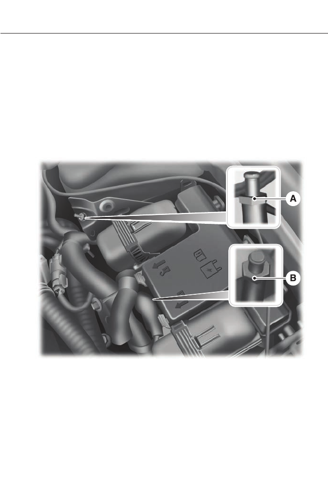
1. Park the booster vehicle close to the
hood of the disabled vehicle making
sure the two vehicles do not touch. Set
the parking brake on both vehicles and
stay clear of the engine cooling fan and
other moving parts.
2. Check all battery terminals and remove
any excessive corrosion before you
attach the battery cables. Ensure that
vent caps are tight and level.
3. Turn the heater fan on in both vehicles
to protect from any electrical surges.
Turn all other accessories off.
Connecting the Jumper Cables
Your vehicle has a 12 volt battery that has
two prongs accessible from under the
hood. Your vehicle can be jumped the
same way conventional vehicles can be
using these prongs. The illustration below
shows the two connector prongs used for
jump-starting your vehicle.
E155827
A. Negative prong (–)
B. Positive prong (+)
Note: In the illustration, the vehicle on the
bottom is used to designate the assisting
(boosting) battery.
Note: Remove the red cap from the positive
prong (B) on your vehicle before connecting
the cables.
220
Roadside Emergencies
E148861
1. Connect the positive (+) jumper cable
to the positive (+) prong (B) of the
discharged battery.
2. Connect the other end of the positive
(+) cable to the positive (+) terminal
of the assisting battery.
3. Connect the negative (-) cable to the
negative (-) terminal of the assisting
battery.
4. Make the final connection of the
negative (-) cable to the negative (-)
prong (A) of your vehicle.
Note: Do not attach the negative (-) cable
to fuel lines, engine rocker covers, the intake
manifold or electrical components as
grounding points.
WARNING
Do not connect the end of the
second cable to the negative (-)
terminal of the battery to be jumped.
A spark may cause an explosion of the
gases that surround the battery.
Ensure that the cables are clear of fan
blades, belts, moving parts of both engines,
or any fuel delivery system parts.
Jump Starting
1. Start the booster vehicle and press the
accelerator moderately.
2. Start the disabled vehicle.
3. Once the disabled vehicle has been
started, run both vehicles for an
additional three minutes before
disconnecting the jumper cables.
Removing the Jumper Cables
Remove the jumper cables in the reverse
order that they were connected.
Note: In the illustration, the vehicle on the
bottom is used to designate the assisting
(boosting) battery.
221
Roadside Emergencies
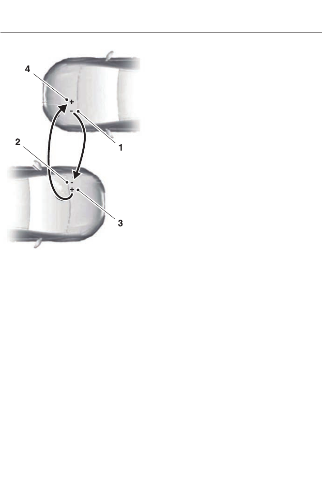
E148862
1. Remove the jumper cable from the
ground metal surface.
2. Remove the jumper cable on the
negative (-) terminal of the booster
vehicle's battery.
3. Remove the jumper cable from the
positive (+) terminal of the booster
vehicle's battery.
4. Remove the jumper cable from the
positive (+) terminal of the disabled
vehicle's battery.
After the disabled vehicle has been started
and the jumper cables removed, allow it
to idle for several minutes so the vehicle
computer can relearn its idle conditions.
COLLISION, DAMAGE OR FIRE
EVENT
Guidance for Ford Motor Company
Electric and Hybrid-Electric
Vehicles Equipped With High
Voltage Batteries
(Vehicle Owner/Operator/General
Public)
Electric and Hybrid-Electric Vehicle
Considerations
In the event of damage or fire involving
an electric vehicle (EV) or
hybrid-electric vehicle (HEV):
• Always assume the high-voltage
battery and associated components
are energized and fully charged.
• Exposed electrical components, wires
and high-voltage batteries present
potential high-voltage shock hazards.
• Venting/off-gassing high-voltage
battery vapors are potentially toxic and
flammable.
• Physical damage to the vehicle or
high-voltage battery may result in
immediate or delayed release of toxic,
flammable gases and fire.
Vehicle Information and General
Safety Practices
• Know the make and model of your
vehicle.
• Review the owner’s manual and
become familiar with your vehicle’s
safety information and recommended
safety practices.
• Do not attempt to repair damaged
electric and hybrid-electric vehicles
yourself. Contact an authorized Ford
Dealer or vehicle manufacturer
representative for service.
222
Roadside Emergencies

Crashes
A crash or impact significant enough to
require an emergency response for
conventional vehicles would also require
the same response for an electric or
hybrid-electric vehicle.
If possible
• Move your car to a safe, nearby
location and remain on the scene.
• Roll down the windows before shutting
your vehicle off.
• Place your vehicle in Park, set the
parking brake, turn off the vehicle,
activate the hazard lights, and move
your key(s) at least 16 feet (5 meters)
away from the vehicle.
Always
• Call 911 if assistance is needed and
advise that an electric or hybrid-electric
vehicle is involved.
• Do not touch exposed electrical
components or the engine
compartment, as a shock hazard may
exist.
• Avoid contact with leaking fluids and
gases, and remain out of the way of
oncoming traffic until emergency
responders arrive.
• When emergency responders arrive,
tell them that the vehicle involved is an
electric vehicle or hybrid vehicle.
Fires
As with any vehicle, call 911 immediately if
you see sparks, smoke or flames coming
from the vehicle.
• Exit the vehicle immediately.
• Advise 911 that an electric or
hybrid-electric vehicle is involved.
• As with any vehicle fire, do not inhale
smoke, vapors or gas from the vehicle,
as they may be hazardous.
• Remain a safe distance upwind and
uphill from the vehicle fire.
• Stay out of the roadway and stay out
of the way of any oncoming traffic
while awaiting the arrival of emergency
responders.
Post-Incident
• Do not store a severely damaged
vehicle with a lithium-ion battery inside
a structure or within 50 feet (15
meters) of any structure or vehicle.
• Make sure that passenger and cargo
compartments remain ventilated (i.e.,
open window, door, or trunk).
• For vehicles in the United States, notify
Ford Motor Company 1-800-392-3673
(then follow the prompts on the voice
response menu), an authorized Ford
dealer or service center as soon as
possible as there may be other steps
to secure and discharge the
high-voltage battery.
• For vehicles in Canada, notify Ford
Motor Company 1-800-565-3673
(then follow the prompts on the voice
response menu), an authorized Ford
dealer or service center as soon as
possible as there may be other steps
to secure and discharge the
high-voltage battery.
• Call 911 if you observe leaking fluids,
sparks, smoke or flames, or hear
gurgling or bubbling from the
high-voltage battery.
223
Roadside Emergencies
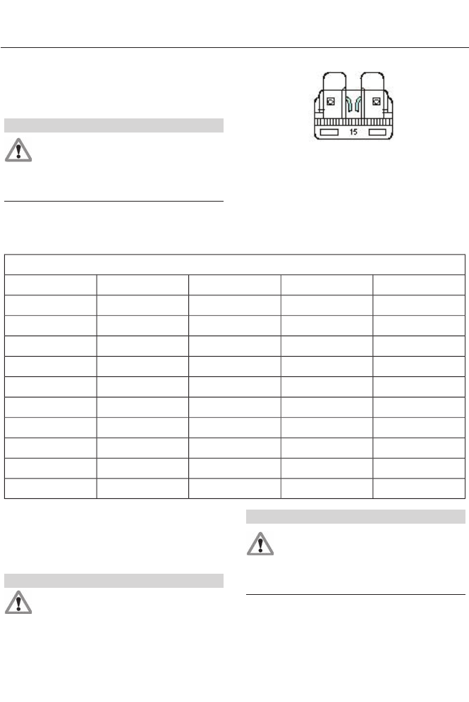
CHANGING A FUSE
Fuses
WARNING
Always replace a fuse with one that
has the specified amperage rating.
Using a fuse with a higher amperage
rating can cause severe wire damage and
could start a fire.
E142430
If electrical components in the vehicle are
not working, a fuse may have blown. Blown
fuses are identified by a broken wire within
the fuse. Check the appropriate fuses
before replacing any electrical
components.
Standard Fuse Amperage Rating and Color
Color
J-type fusesM-type fusesDual micro fusesMicro fusesFuse rating
--TanTan5A
--BrownBrown7.5A
--RedRed10A
-GreyBlueBlue15A
BlueLight Blue-Yellow20A
WhiteWhite-White25A
PinkPink-Green30A
GreenGreen--40A
Red---50A
Yellow---60A
FUSE SPECIFICATION CHART
Power Distribution Box
WARNINGS
Always disconnect the battery before
servicing high-current fuses.
WARNINGS
To reduce risk of electrical shock,
always replace the cover to the
power distribution box before
reconnecting the battery or refilling fluid
reservoirs.
224
Fuses
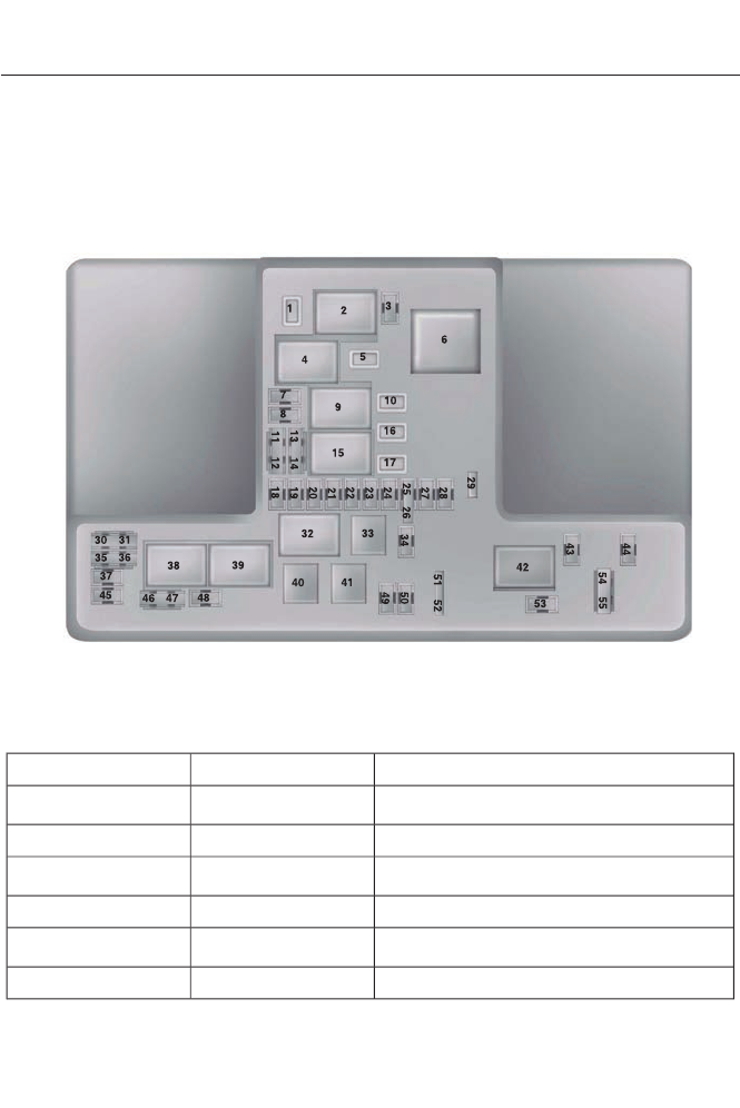
The power distribution box is located in
the engine compartment. It has
high-current fuses that protect your
vehicle's main electrical systems from
overloads.
If the battery has been disconnected and
reconnected, some features will need to
be reset. See Changing the 12V Battery
(page 243).
E144783
The high-current fuses are coded as
follows:
Protected componentsFuse amp ratingFuse or relay number
Wiper motor #2
25A3
1
Not used—2
Autowipers
15A1
3
Blower motor relay—4
Power point 3 - Back of console
20A3
5
Not used—6
225
Fuses

Protected componentsFuse amp ratingFuse or relay number
Powertrain control module - vehicle power
1
20A1
7
Powertrain control module - vehicle power
2
20A1
8
Powertrain control module relay—9
Power point 1 - driver front
20A3
10
Powertrain control module - vehicle power
4
15A2
11
Powertrain control module - vehicle power
3
15A2
12
Not used (spare)
10A2
13
Not used (spare)
10A2
14
Run/start relay—15
Power point 2 - console
20A3
16
Transmission oil (Fusion Energi)
20A3
17
Powertrain and hybrid powertrain control
module - keep alive power
10A1
18
Run/start electronic power assist steering
10A1
19
Run/start lighting
10A1
20
Run/start hybrid powertrain control
module
15A1
21
Not used—22
Run/start: blind spot information system,
Rear view camera, Adaptive cruise control,
Heads-up display
15A1
23
Run/start transmission oil pump (Fusion
Energi)
10A1
24
Run/start anti-lock brake system
10A2
25
Run/start powertrain control module
10A2
26
226
Fuses

Protected componentsFuse amp ratingFuse or relay number
Fuel door solenoid (Fusion Energi)
10A1
27
Not used—28
Hybrid content vehicle power 5
15A1
29
Not used—30
Not used—31
Cooling fan relay (Hybrid)—32
Not used—33
Not used—34
Charger (Fusion Energi)
15A2
35
Battery electric control module fan (Fusion
Energi)
15A2
36
Not used—37
Vacuum pump #1 relay—38
Vacuum pump #2 relay—39
Fuel pump relay—40
Horn relay—41
Not used—42
Not used—43
Not used—44
Vacuum pump monitor
5A1
45
Charge port light ring
10A2
46
Brake on/off switch
10A2
47
Horn
20A1
48
Not used—49
Not used—50
227
Fuses
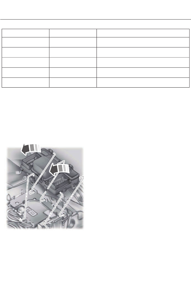
Protected componentsFuse amp ratingFuse or relay number
Hybrid content vehicle power 1
15A2
51
Hybrid content vehicle power 2
15A2
52
Power seats
10A1
53
Hybrid content vehicle power 4
10A2
54
Hybrid content vehicle power 3
10A2
55
1Micro fuse
2Dual micro fuse
3M-type fuse
Power Distribution Box - Bottom
E145983
There are fuses located on the bottom of
the fuse box. To access the bottom of the
fuse box, do the following:
1. Release the two latches, located on
both sides of the fuse box.
2. Raise the inboard side of the fuse box
from the cradle.
3. Move the fuse box toward the center
of the engine compartment.
4. Pivot the outboard side of the fuse box
to access the bottom side.
228
Fuses
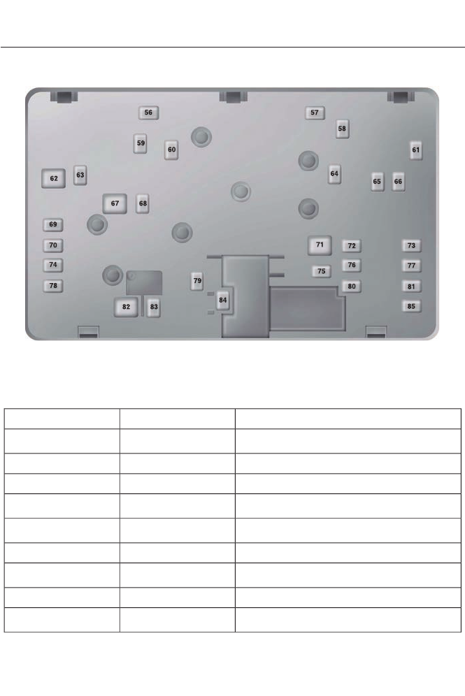
E144949
The high-current fuses are coded as
follows:
Protected componentsFuse amp ratingFuse or relay number
Fuel pump feed
30A1
56
Not used—57
Not used—58
Vacuum pump relay
40A1
59
PWM fan
40A1
60
Not used—61
Body control module 1
50A2
62
Not used—63
Charger B+ output (Fusion Energi)
40A1
64
229
Fuses

Protected componentsFuse amp ratingFuse or relay number
Front heated seat
20A1
65
Not used—66
Body control module 2
50A2
67
Heated rear window
40A1
68
Anti-lock brake system valves
30A1
69
Passenger seat
30A1
70
Not used—71
Not used (spare)
30A1
72
Not used (spare)
20A1
73
Driver seat module
30A1
74
Not used—75
Not used (spare)
20A1
76
Not used (spare)
30A1
77
Not used—78
Blower motor
40A1
79
Not used (spare)
30A1
80
110 volt inverter
40A1
81
Anti-lock brake system pump
60A2
82
Wiper motor #1
25A1
83
Not used—84
Not used (spare)
30A1
85
1 M-type fuse
2J-type fuse
230
Fuses
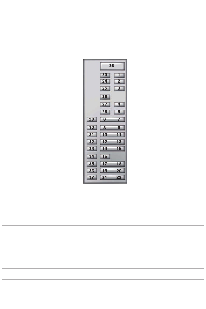
Passenger Compartment Fuse
Panel
The fuse panel is located under the
instrument panel to the left of the steering
column.
Note: It may be easier to access the fuse
panel if you remove the finish trim piece.
E145984
The fuses are coded as follows:
Protected componentsFuse amp ratingFuse or relay number
Lighting (ambient, glove box, vanity, dome,
trunk)
10A1
1
Memory seats, Lumbar, Power mirror
7.5A1
2
Driver door unlock
20A1
3
Not used (spare)
5A1
4
Subwoofer amplifier
20A1
5
Not used (spare)
10A2
6
231
Fuses

Protected componentsFuse amp ratingFuse or relay number
Not used (spare)
10A2
7
Not used (spare)
10A2
8
Not used (spare)
10A2
9
Keypad, Cell phone passport module
(Fusion Energi)
5A2
10
Not used (spare)
5A2
11
Climate control, Gear shift
7.5A2
12
Steering wheel column, Cluster, Datalink
logic
7.5A2
13
Traction battery control module (Hybrid)
10A2
14
Datalink/Gateway module
10A2
15
Trunk release
15A1
16
Not used (spare)
5A2
17
Ignition, Push button stop/start
5A2
18
Passenger airbag disabled indicator,
Transmission range
5A2
19
Not used (spare)
5A2
20
Humidity and in–car temperature (Hybrid)
5A2
21
Occupant classification sensor
5A2
22
Delayed Accessory (Power inverter logic,
Moonroof logic)
10A1
23
Central lock/unlock
30A1
24
Driver door (window, mirror)
30A1
25
Front passenger door (window, mirror)
30A1
26
Moonroof
30A1
27
232
Fuses

Protected componentsFuse amp ratingFuse or relay number
Sony amplifier
20A1
28
Rear driver side door (window)
30A1
29
Rear passenger side door (window)
30A1
30
Not used (spare)
15A1
31
GPS, Voice control, Display, Adaptive cruise
control, Radio frequency receiver
10A1
32
Radio, Active noise control
20A1
33
Run/start (fuse #19, 20, 21, 22, 35, 36, 37,
circuit breaker)
30A1
34
Restraints control module
5A1
35
Auto-dimming rear view mirror
15A1
36
Not used (spare)
15A1
37
Not used (spare)30A38
1Micro fuse
2Dual micro fuse
233
Fuses
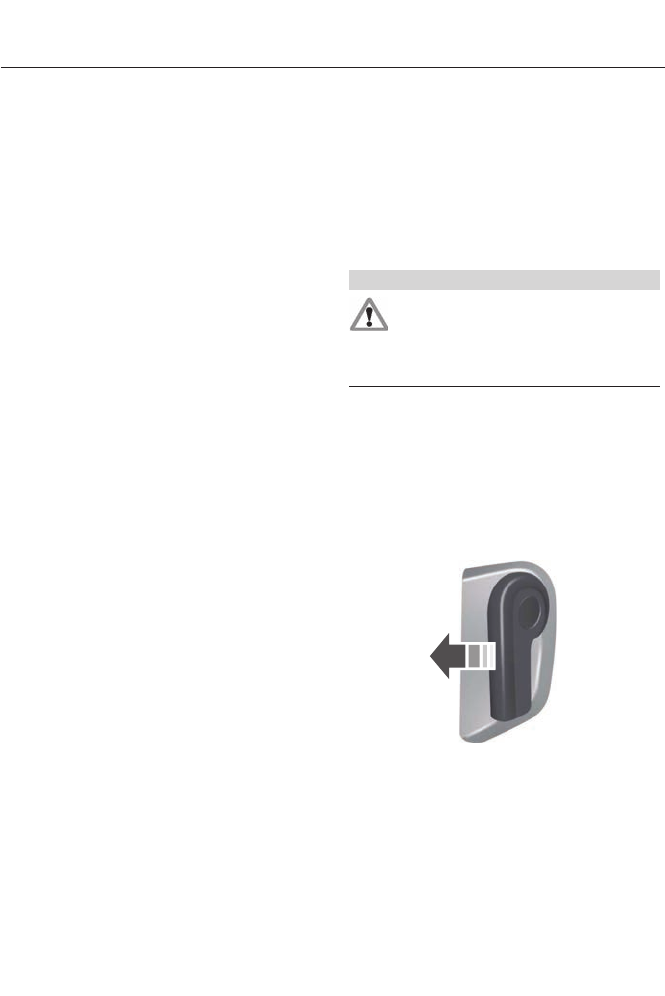
GENERAL INFORMATION
Have your vehicle serviced regularly to help
maintain its roadworthiness and resale
value. There is a large network of Ford
authorized dealers that are there to help
you with their professional servicing
expertise. We believe that their specially
trained technicians are best qualified to
service your vehicle properly and expertly.
They are supported by a wide range of
highly specialized tools developed
specifically for servicing your vehicle.
To help you service your vehicle, we
provide scheduled maintenance
information which makes tracking routine
service easy. See Scheduled
Maintenance (page 438).
If your vehicle requires professional service,
your authorized dealer can provide the
necessary parts and service. Check your
warranty information to find out which
parts and services are covered.
Use only recommended fuels, lubricants,
fluids and service parts conforming to
specifications. Motorcraft® parts are
designed and built to provide the best
performance in your vehicle.
Precautions
• Do not work on a hot engine.
• Make sure that nothing gets caught in
moving parts.
• Do not work on a vehicle with the
engine running in an enclosed space,
unless you are sure you have enough
ventilation.
• Keep all open flames and other burning
material (such as cigarettes) away
from the battery and all fuel related
parts.
Working with the Engine Off
1. Set the parking brake and shift to P
(Park).
2. Turn off the engine and remove the key
(if equipped).
3. Block the wheels.
Working with the Engine On
WARNING
To reduce the risk of vehicle damage
and/or personal burn injuries, do not
start your engine with the air cleaner
removed and do not remove it while the
engine is running.
1. Set the parking brake and shift to P
(Park).
2. Block the wheels
OPENING AND CLOSING THE
HOOD
E142457
1. To open the hood, go inside the vehicle
and pull the hood release handle
located under the left hand side of the
instrument panel.
234
Maintenance
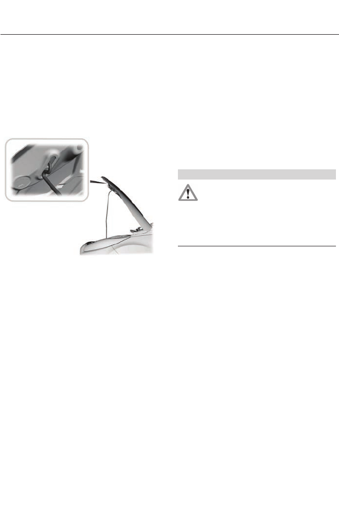
2. Go to the front of the vehicle and
locate the secondary release lever,
which is located under the front of the
hood, to your right of the center of the
vehicle (driver's side), near the
headlight.
3. Release the hood latch by pushing the
yellow secondary release lever to your
left, toward the center of the vehicle.
E87786
4. Raise the hood and support it with the
prop rod.
5. To close the hood, lower and secure
the prop rod in the clip.
6. Lower the hood and allow it to drop the
last 10-12 inches (25 to 30
centimeters).
Note: Make sure that the hood is closed
properly and fully latched on both sides of
the hood.
UNDER HOOD OVERVIEW -
2.0L HYBRID
WARNING
The inverter system controller
contains various high-voltage
components that can cause serious
bodily harm or death. The inverter system
controller is not serviceable and should
never be touched, probed, or tampered
with.
Note: Do not attempt to service any of the
high-voltage components or wiring. For
easier identification, the high-voltage wiring
insulation is color coated orange.
235
Maintenance
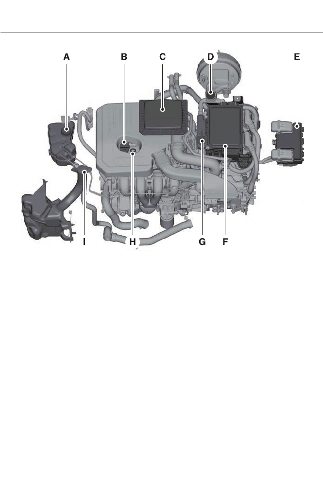
E146046
Engine coolant reservoir capA
Engine oil filler capB
Engine air cleaner coverC
Brake fluid reservoir capD
Power distribution boxE
Inverter system controllerF
Inverter system controller coolant reservoir capG
Engine oil dipstickH
Windshield washer fluid reservoir capI
236
Maintenance
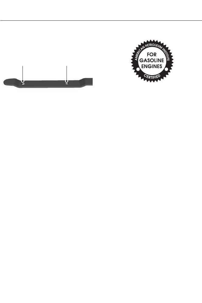
ENGINE OIL DIPSTICK - 2.0L
HYBRID
A B
E146094
MINA
MAXB
ENGINE OIL CHECK
Note: Check the level before starting the
engine.
Note: Make sure that the level is between
the MIN and the MAX marks.
1. Make sure that your vehicle is on level
ground.
2. Turn the engine off and wait 10 minutes
for the oil to drain into the oil pan.
3. Remove the dipstick and wipe it with
a clean, lint-free cloth. Replace the
dipstick and remove it again to check
the oil level.
If the level is at the MIN mark, add oil
immediately.
Adding Engine Oil
Note: Do not remove the filler cap when
the engine is running.
Note: Do not add oil further than the MAX
mark. Oil levels above the MAX mark may
cause engine damage.
E142732
Only use oils certified for gasoline engines
by the American Petroleum Institute (API).
An oil with this trademark symbol
conforms to the current engine and
emission system protection standards and
fuel economy requirements of the
International Lubricants Specification
Advisory Council (ILSAC), comprised of
U.S. and Japanese automobile
manufacturers.
1. Remove the filler cap.
2. Add engine oil that meets the Ford
specifications. See Capacities and
Specifications (page ?).
3. Replace the filler cap. Turn it until you
feel a strong resistance.
Resetting the Oil Life Monitoring
System
Note: Reset the oil life monitoring only after
an oil change.
1. Turn the ignition key to the on position.
Do not start the engine. For vehicles
with push-button start, press and hold
the start button for two seconds
without pressing the brake pedal. Do
not attempt to start the engine.
2. Press both the accelerator and brake
pedals at the same time.
3. Keep both pedals fully pressed.
237
Maintenance

4. After three seconds, the Service: Oil
reset in prog. message will be
displayed.
5. After 25 seconds, the Service: Oil reset
complete message will be displayed.
6. Release both the accelerator and brake
pedals.
7. The Service: Oil reset complete
message will no longer be displayed.
8. Rotate the key to the off position. For
vehicles with push-button start, press
the start button to turn the vehicle off
completely.
Oil Maintenance Mode (If Equipped)
The oil maintenance mode is equipped on
Energi models only. The oil maintenance
mode keeps the engine oil quality in good
condition when you drive the vehicle with
limited engine use. If the vehicle is in oil
maintenance mode when you start the
vehicle, a message will appear in the
instrument cluster. While the vehicle is in
oil maintenance mode, the vehicle will run
the engine as necessary.
If you select the EV Now mode while the
vehicle is in the oil maintenance mode, the
oil maintenance mode will be suspended
for as long as you continue driving the
vehicle. The oil maintenance mode will
resume the next time you start the vehicle.
Changing the engine oil and resetting the
oil life monitoring system will suspend the
oil maintenance mode.
ENGINE COOLANT CHECK
Engine Coolant and Inverter
System Controller Coolant
Your vehicle is equipped with two separate
cooling systems. One is for cooling the
engine and one is for cooling the inverter
system controller that is specific to the
hybrid operating system. The two systems
operate similarly, with the inverter system
controller cooling system generally
operating at a lower temperature and
pressure.
Checking the Engine Coolant
When the engine is cold, check the
concentration and level of the engine
coolant at the intervals listed in the
scheduled maintenance information. See
Scheduled Maintenance (page 438).
Note: Make sure that the level is between
the MIN and MAX marks on the engine
coolant reservoir.
Note: Coolant expands when it is hot. The
level may extend beyond the MAX mark.
Note: If the level is at the MIN mark, below
the MIN mark, or empty, add prediluted
coolant immediately. See Adding Engine
Coolant in this chapter.
The coolant concentration should be
maintained within 48% to 50%, which
equates to a freeze point between -30°F
(-34°C) and -34°F (-37°C).
Note: For best results, coolant
concentration should be tested with a
refractometer such as Rotunda tool
300-ROB75240 available from your dealer.
Ford does not recommend the use of
hydrometers or coolant test strips for
measuring coolant concentrations.
238
Maintenance
Note: Automotive fluids are not
interchangeable. Do not use engine coolant
or antifreeze or windshield washer fluid
outside of its specified function and vehicle
location.
Checking the Inverter System
Controller Coolant
When the engine is cold, check the
concentration and level of the inverter
system controller coolant at the intervals
listed in the scheduled maintenance
information. See Scheduled
Maintenance (page 438).
Note: Make sure that the level is between
the MIN and MAX marks on the inverter
system controller coolant reservoir.
Note: Coolant expands when it is hot. The
level may extend beyond the MAX mark.
Note: If the level is at the MIN mark, below
the MIN mark, or empty, add prediluted
coolant immediately. See Adding Inverter
System Controller Coolant in this chapter.
The coolant concentration should be
maintained within 48% to 50%, which
equates to a freeze point between -30°F
(-34°C) and -34°F (-37°C).
Note: For best results, coolant
concentration should be tested with a
refractometer such as Rotunda tool
300-ROB75240 available from your dealer.
Ford does not recommend the use of
hydrometers or coolant test strips for
measuring coolant concentrations.
Note: Automotive fluids are not
interchangeable. Do not use engine coolant
or antifreeze or windshield washer fluid
outside of its specified function and vehicle
location.
Adding Coolant
WARNINGS
Do not add engine coolant when the
engine is hot. Steam and scalding
liquids released from a hot cooling
system can burn you badly. Also, you can
be burned if you spill coolant on hot engine
parts.
Do not put engine coolant in the
windshield washer fluid container. If
sprayed on the windshield, engine
coolant could make it difficult to see
through the windshield.
To reduce the risk of personal injury,
make sure the engine is cool before
unscrewing the coolant pressure
relief cap. The cooling system is under
pressure; steam and hot liquid can come
out forcefully when the cap is loosened
slightly.
Do not add coolant further than the
MAX mark.
Note: Do not use stop leak pellets, cooling
system sealants, or additives as they can
cause damage to the cooling or heating
systems. This damage would not be covered
under your vehicle’s warranty.
Note: During normal vehicle operation, the
coolant may change color from orange to
pink or light red. As long as the coolant is
clear and uncontaminated, this color change
does not indicate the coolant has degraded
nor does it require the coolant to be drained,
the system to be flushed, or the coolant to
be replaced.
Note: It is very important to use prediluted
coolant meeting the Ford specification in
order to avoid plugging the small coolant
passageways. Use of concentrated coolant
and water may cause coolant passageway
plugging and void the warranty. See
Capacities and Specifications (page 290).
239
Maintenance

• Do not mix different colors or types of
coolant in your vehicle. Make sure the
correct coolant is used. Mixing of
coolants may harm your cooling
system. The use of an improper coolant
may harm the engine, inverter system
controller, and cooling system
components and may void the
warranty.
• In case of emergency, a large amount
of water without engine coolant may
be added to the engine cooling system
only in order to reach a vehicle service
location. In this instance, the engine
cooling system must be drained,
chemically cleaned with Motorcraft
Premium Cooling System Flush, and
refilled with prediluted engine coolant
as soon as possible. Water alone
(without engine coolant) can cause
engine damage from corrosion,
overheating, or freezing. DO NOT use
this method for the inverter system
controller cooling system. The inverter
system controller cooling system
operates close to ambient
temperature, and is susceptible to
freezing in any subfreezing environment
in the absence of coolant.
• Do not use alcohol, methanol, brine or
any engine coolants mixed with alcohol
or methanol antifreeze (coolant).
Alcohol and other liquids can cause
engine damage from overheating or
freezing.
• Do not add extra inhibitors or additives
to the coolant. These can be harmful
and compromise the corrosion
protection of the engine coolant.
Adding Engine Coolant
1. Unscrew the engine coolant reservoir
cap slowly. Any pressure will escape
as you unscrew the cap.
2. Use a funnel to add prediluted engine
coolant to the engine coolant reservoir.
Make sure that the level is between the
MIN and MAX marks on the engine
coolant reservoir. Use prediluted engine
coolant meeting the Ford specification.
See Capacities and Specifications
(page 290).
3. Close the engine coolant reservoir cap.
Whenever you add coolant, check the
coolant level in the engine coolant reservoir
the next few times you drive the vehicle. If
necessary, add enough prediluted engine
coolant to bring the engine coolant level
to the proper level.
Adding Inverter System Controller
Coolant
1. Open the inverter system controller
coolant reservoir cap.
2. Use a funnel to add prediluted coolant
to the inverter system controller
coolant reservoir. Make sure that the
level is between the MIN and MAX
marks on the inverter system controller
coolant reservoir. Use prediluted
coolant meeting the Ford specification.
See Capacities and Specifications
(page 290).
3. Close the inverter system controller
coolant reservoir cap.
Whenever you add coolant, check the
coolant level in the inverter system
controller coolant reservoir the next few
times you drive the vehicle. If necessary,
add enough prediluted coolant to bring the
inverter system controller coolant level to
the proper level.
Recycled Engine Coolant
Ford Motor Company does not recommend
the use of recycled engine coolant since a
Ford-approved recycling process is not yet
available.
240
Maintenance

Used engine coolant should be disposed
of in an appropriate manner. Follow your
community’s regulations and standards
for recycling and disposing of automotive
fluids.
Severe Climates
If you drive in extremely cold climates:
• It may be necessary to have an
authorized Ford dealer increase the
coolant concentration above 50%.
• A coolant concentration of 60% will
provide improved freeze point
protection. Engine coolant
concentrations above 60% will
decrease the overheat protection
characteristics of the engine coolant
and may cause engine damage.
If you drive in extremely hot climates:
• It may be necessary to have an
authorized Ford dealer decrease the
coolant concentration to 40%.
• A coolant concentration of 40% will
provide improved overheat protection.
Engine coolant concentrations below
40% will decrease the corrosion/freeze
protection characteristics of the engine
coolant and may cause engine
damage.
Vehicles driven year-round in non-extreme
climates should use prediluted coolant
meeting the Ford specification for
optimum cooling system and engine
protection.
What You Should Know About Fail-
Safe Cooling
If the engine coolant supply is depleted,
this feature allows the vehicle to be driven
temporarily before incremental component
damage is incurred. The “fail-safe”
distance depends on ambient
temperatures, vehicle load and terrain.
How Fail-Safe Cooling Works
If the engine begins to overheat, the engine
coolant temperature gauge will move to
the red (hot) area and:
The coolant temperature
warning light will illuminate.
The service engine soon
indicator will illuminate.
If the engine reaches a preset
over-temperature condition, the engine
will automatically switch to alternating
cylinder operation. Each disabled cylinder
acts as an air pump and cools the engine.
When this occurs the vehicle will still
operate. However:
• The engine power will be limited.
• The air conditioning system will be
disabled.
Continued operation will increase the
engine temperature and the engine will
completely shut down, causing steering
and braking effort to increase.
Once the engine temperature cools, the
engine can be re-started. Take your vehicle
to an authorized dealer as soon as possible
to minimize engine damage.
When Fail-Safe Mode Is Activated
WARNINGS
Fail-safe mode is for use during
emergencies only. Operate the
vehicle in fail-safe mode only as long
as necessary to bring the vehicle to rest in
a safe location and seek immediate repairs.
When in fail-safe mode, the vehicle will
have limited power, will not be able to
maintain high-speed operation, and may
completely shut down without warning,
potentially losing engine power, power
steering assist, and power brake assist,
which may increase the possibility of a
crash resulting in serious injury.
241
Maintenance

WARNINGS
Never remove the coolant reservoir
cap while the engine is running or hot.
Note: Driving the vehicle without repairing
the engine problem increases the chance of
engine damage. Take your vehicle to an
authorized dealer as soon as possible.
You have limited engine power when in the
fail-safe mode, so drive the vehicle with
caution. The vehicle will not be able to
maintain high-speed operation and the
engine will run rough. Remember that the
engine is capable of completely shutting
down automatically to prevent engine
damage, therefore:
1. Pull off the road as soon as safely
possible and turn off the engine.
2. Arrange for the vehicle to be taken to
an authorized dealer.
3. If this is not possible, wait a short
period for the engine to cool.
4. Check the coolant level and replenish
if low.
5. Re-start the engine and take your
vehicle to an authorized dealer.
AUTOMATIC TRANSMISSION
FLUID CHECK
Note: Transmission fluid should be checked
by an authorized dealer. If required, fluid
should be added by an authorized dealer.
The automatic transmission does not have
a transmission fluid dipstick.
Have an authorized dealer check and
change the transmission fluid at the
correct service interval. See Scheduled
Maintenance (page ?). Your
transmission does not consume fluid.
However, the fluid level should be checked
if the transmission is not working properly,
(i.e., if the transmission slips or shifts
slowly) or if you notice some sign of fluid
leakage.
Do not use supplemental transmission
fluid additives, treatments or cleaning
agents. The use of these materials may
affect transmission operation and result
in damage to internal transmission
components.
BRAKE FLUID CHECK
Fluid levels between the MIN and MAX
lines are within the normal operating range;
there is no need to add fluid. If the fluid
levels are outside of the normal operating
range, the performance of the system
could be compromised; seek service from
your authorized dealer immediately.
POWER STEERING FLUID
CHECK
Your vehicle is equipped with an electric
power steering (EPS) system. There is no
fluid reservoir to check or fill.
FUEL FILTER
Your vehicle is equipped with a lifetime
fuel filter that is integrated with the fuel
tank. Regular maintenance or replacement
is not needed.
242
Maintenance
WASHER FLUID CHECK
WARNING
If you operate your vehicle in
temperatures below 40°F (5°C), use
washer fluid with antifreeze
protection. Failure to use washer fluid with
antifreeze protection in cold weather could
result in impaired windshield vision and
increase the risk of injury or accident.
Add fluid to fill the reservoir if the level is
low. Only use a washer fluid that meets
Ford specifications. See Capacities and
Specifications (page 286).
State or local regulations on volatile
organic compounds may restrict the use
of methanol, a common windshield washer
antifreeze additive. Washer fluids
containing non-methanol antifreeze
agents should be used only if they provide
cold weather protection without damaging
the vehicle’s paint finish, wiper blades or
washer system.
CHANGING THE 12V BATTERY
WARNINGS
Batteries normally produce explosive
gases which can cause personal
injury. Therefore, do not allow
flames, sparks or lighted substances to
come near the battery. When working near
the battery, always shield your face and
protect your eyes. Always provide proper
ventilation.
When lifting a plastic-cased battery,
excessive pressure on the end walls
could cause acid to flow through the
vent caps, resulting in personal injury and
damage to the vehicle or battery. Lift the
battery with a battery carrier or with your
hands on opposite corners.
WARNINGS
Keep batteries out of reach of
children. Batteries contain sulfuric
acid. Avoid contact with skin, eyes or
clothing. Shield your eyes when working
near the battery to protect against possible
splashing of acid solution. In case of acid
contact with skin or eyes, flush
immediately with water for a minimum of
15 minutes and get prompt medical
attention. If acid is swallowed, call a
physician immediately.
Your vehicle is equipped with a
Motorcraft® maintenance-free battery
which normally does not require additional
water during its life of service.
Note: If your battery has a cover/shield,
make sure it is reinstalled after the battery
has been cleaned or replaced.
Note: See an authorized dealer for low
voltage battery access, testing, or
replacement.
When a low voltage battery replacement
is necessary, see an authorized dealer to
replace the low voltage battery with a Ford
recommended replacement low voltage
battery that matches the electrical
requirements of the vehicle
To ensure proper operation of the battery
management system (BMS), do not allow
a technician to connect any electrical
device ground connection directly to the
low voltage battery negative post. A
connection at the low voltage battery
negative post can cause inaccurate
measurements of the battery condition
and potential incorrect system operation.
Note: Note: If a person adds electrical or
electronic accessories or components to the
vehicle, the accessories or components may
adversely affect the low voltage battery
performance and durability and may also
affect the performance of other electrical
systems in the vehicle.
243
Maintenance

For longer, trouble-free operation, keep the
top of the battery clean and dry. Also,
make certain the battery cables are always
tightly fastened to the battery terminals.
If you see any corrosion on the battery or
terminals, remove the cables from the
terminals and clean with a wire brush. You
can neutralize the acid with a solution of
baking soda and water.
When a battery replacement is required,
the battery should only be replaced with
a Ford recommended replacement battery
that matches the electrical requirements
of the vehicle.
Because your vehicle’s engine is
electronically-controlled by a computer,
some engine control settings are
maintained by power from the low voltage
battery. Some engine computer settings,
like the idle trim and fuel trim strategy,
optimize the driveability and performance
of the engine. Some other computer
settings, like the clock and radio station
presets, are also maintained in memory by
power from the low voltage battery. When
a technician disconnects and connects the
low voltage battery, these settings are
erased. Complete the following procedure
in order to restore the settings:
1. With the vehicle at a complete stop,
set the parking brake.
2. Shift the transmission into P.
3. Turn off all accessories.
4. Step on the brake pedal and start the
vehicle.
5. Run the engine until it reaches normal
operating temperature. While the
engine is warming up, complete the
following: Reset the clock. See Audio
System (page 297). Reset the power
windows bounce-back feature. See
Windows and Mirrors (page 72).
Reset the radio station presets. See
Audio System (page 297).
6. Allow the engine to idle for at least one
minute. If the engine turns off, step on
the accelerator to start the engine.
7. While the engine is running, step on the
brake pedal and shift the transmission
to N.
8. Allow the engine to run for at least one
minute by pressing on the accelerator
pedal.
9. Drive the vehicle at least 10 miles (16
kilometers) to completely relearn the
idle and fuel trim strategy.
Note: If you do not allow the engine to
relearn the idle and fuel trim strategy, the
idle quality of your vehicle may be adversely
affected until the engine computer
eventually relearns the idle trim and fuel
trim strategy.
Note: Always dispose of automotive
batteries in a responsible manner. Follow
your local authorized standards for disposal.
Call your local authorized recycling center
to find out more about recycling automotive
batteries.
Note: It is recommended that the negative
battery cable terminal be disconnected from
the battery if you plan to store your vehicle
for an extended period of time.
CHECKING THE WIPER
BLADES
E142463
Run the tip of your fingers over the edge of
the blade to check for roughness.
244
Maintenance
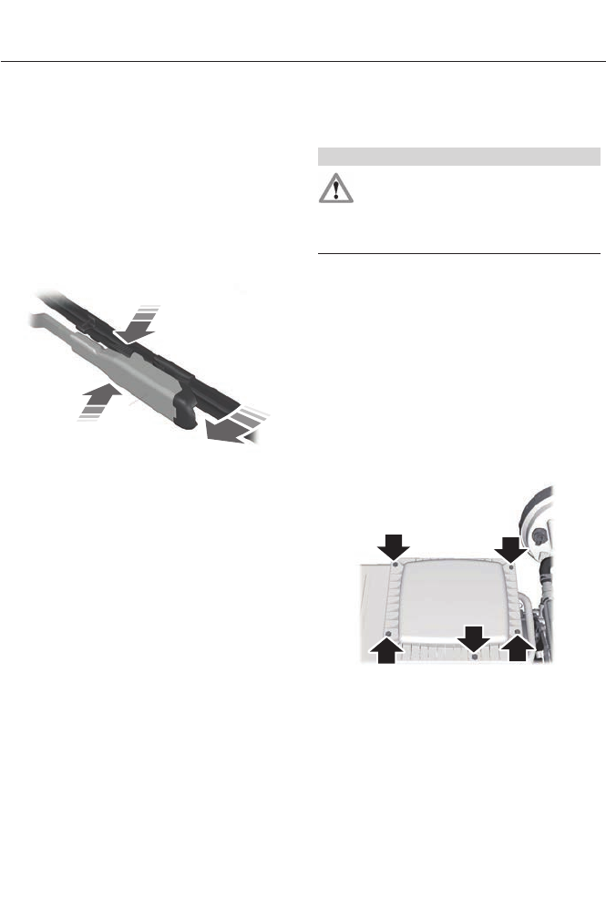
Clean the wiper blades with washer fluid
or water applied with a soft sponge or
cloth.
CHANGING THE WIPER
BLADES
The wiper arms can be manually moved
when the ignition is off. This allows for ease
of blade replacement and cleaning under
the blades.
E129990
1
1
2
1. Pull the wiper blade and arm away
from the glass.
2. Press the locking buttons together.
3. Rotate and remove the wiper blade.
4. Install in the reverse order.
Note: Make sure that the wiper blade locks
into place. Lower the wiper arm and blade
back to the windshield. The wiper arms will
automatically return to their normal position
when the ignition is turned on.
Replace wiper blades at least once per
year for optimum performance.
Poor wiper quality can be improved by
cleaning the wiper blades and the
windshield.
CHANGING THE ENGINE AIR
FILTER
WARNING
To reduce the risk of vehicle damage
and/or personal burn injuries do not
start your engine with the air cleaner
removed and do not remove it while the
engine is running.
When changing the air filter element, use
only the air filter element listed. See
Capacities and Specifications (page
286).
Change the air filter element at the proper
interval. See Scheduled Maintenance
(page 438).
Note: Failure to use the correct air filter
element may result in severe engine
damage. The customer warranty may be
void for any damage to the engine if the
correct air filter element is not used.
E146048
1. Loosen the 5 bolts on the air cleaner
cover.
2. Remove the air cleaner cover.
3. Remove the engine air filter element
from the engine air cleaner assembly.
4. Wipe any dirt or debris from the air filter
housing and cover to make sure no dirt
gets in the engine and to make sure you
have a good seal.
245
Maintenance
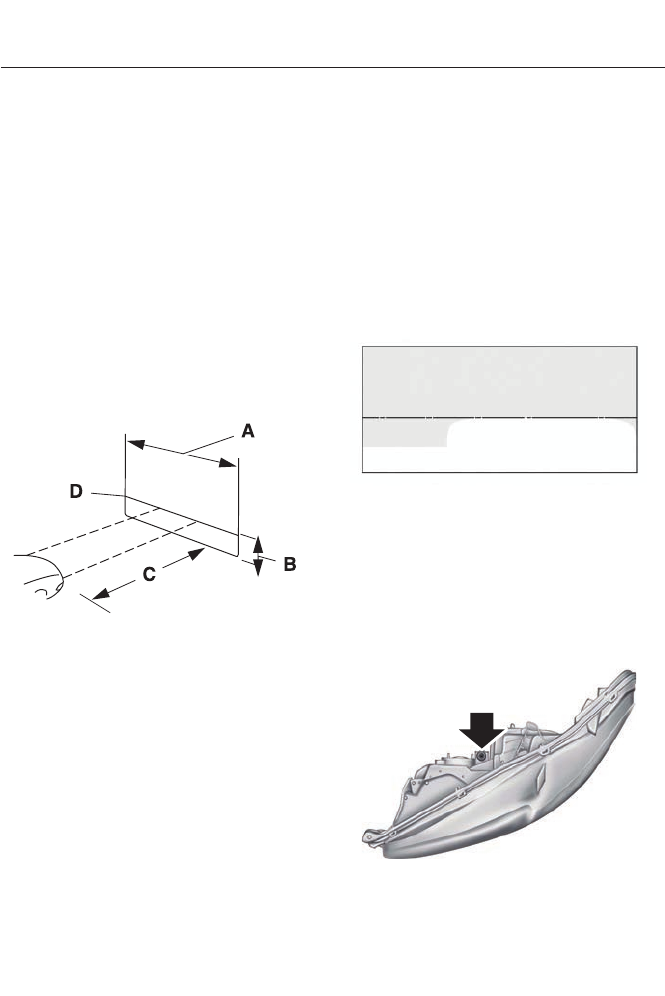
5. Install the new engine air filter element
to the engine air cleaner assembly.
6. Install the air cleaner cover.
7. Tighten the 5 bolts to the air cleaner
cover.
ADJUSTING THE HEADLAMPS
Vertical Aim Adjustment
The headlamps on your vehicle are
properly aimed at the assembly plant. If
your vehicle has been in an accident, the
alignment of your headlamps should be
checked by your authorized dealer.
Headlamp Aiming Target
E142592
8 feet (2.4 meters)A
Center height of lamp to groundB
25 feet (7.6 meters)C
Horizontal reference lineD
Vertical Aim Adjustment Procedure
1. Park the vehicle directly in front of a
wall or screen on a level surface,
approximately 25 feet (7.6 meters)
away.
2. Measure the height of the headlamp
bulb center from the ground and mark
an 8 foot (2.4 meter) horizontal
reference line on the vertical wall or
screen at this height.
Note: To see a clearer light pattern for
adjusting, you may want to block the light
from one headlamp while adjusting the
other.
3. Turn on the low beam headlamps to
illuminate the wall or screen and open
the hood.
E142465
4. On the wall or screen you will observe
a flat zone of high intensity light
located at the top of the right hand
portion of the beam pattern. If the top
edge of the high intensity light zone is
not at the horizontal reference line, the
headlamp will need to be adjusted.
E145594
246
Maintenance
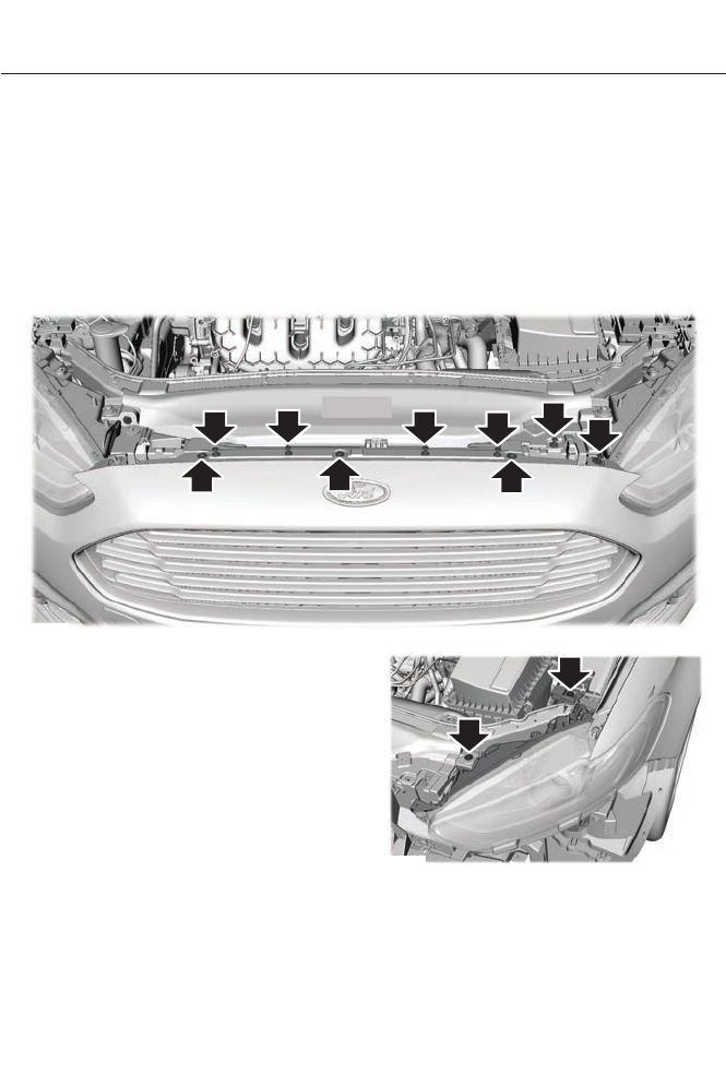
5. Locate the vertical adjuster on each
headlamp. Using a Phillips #2
screwdriver, turn the adjuster either
clockwise or counterclockwise in order
to adjust the vertical aim of the
headlamp. The horizontal edge of the
brighter light should touch the
horizontal reference line.
6. Close the hood and turn off the lamps.
Horizontal Aim Adjustment
Horizontal aim is not required for this
vehicle and is not adjustable.
REMOVING A HEADLAMP
1. Make sure the headlamp control is in
the Off position and open the hood.
E159693
1. Remove the six fasteners securing the
front fascia to the front trim cover.
2. Remove the three bumper cover upper
screws.
3. Remove the fastener at the inboard
side of the headlamp to be serviced.
E159694
4. Remove the two headlamp assembly
screws.
247
Maintenance
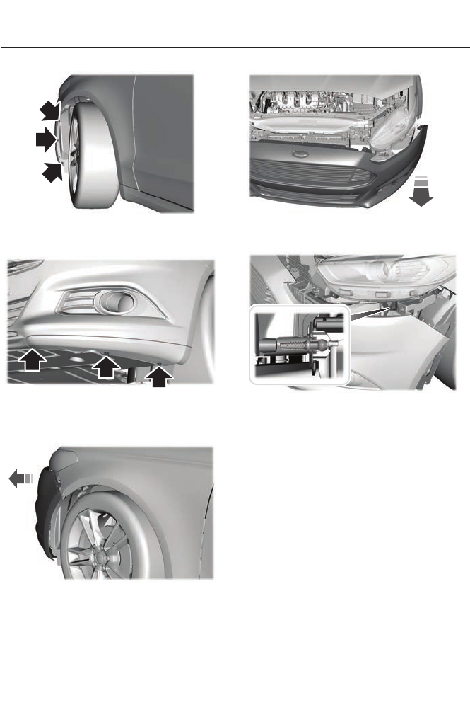
E159695
5. Remove the lower three wheelhousing
fasteners.
E159696
6. Remove the three front bumper cover
lower fasteners, only on the side of
headlamp being serviced.
E159697
7. Separate the front bumper cover from
the fender, pull the fender outward 3
cm.
E159698
8. From the front of the vehicle, pull the
front bumper cover forward 10 cm.
E159699
9. Carefully pull the headlamp assembly
outward to disengage it from the lower
fixing point.
10. Carefully lift the headlamp and
remove from vehicle.
11. Disconnect the electrical connector.
CHANGING A BULB
Lamp Assembly Condensation
Exterior lamps are vented to
accommodate normal changes in pressure.
Condensation can be a natural by-product
of this design. When moist air enters the
lamp assembly through the vents, there is
a possibility that condensation can occur
when the temperature is cold. When
248
Maintenance
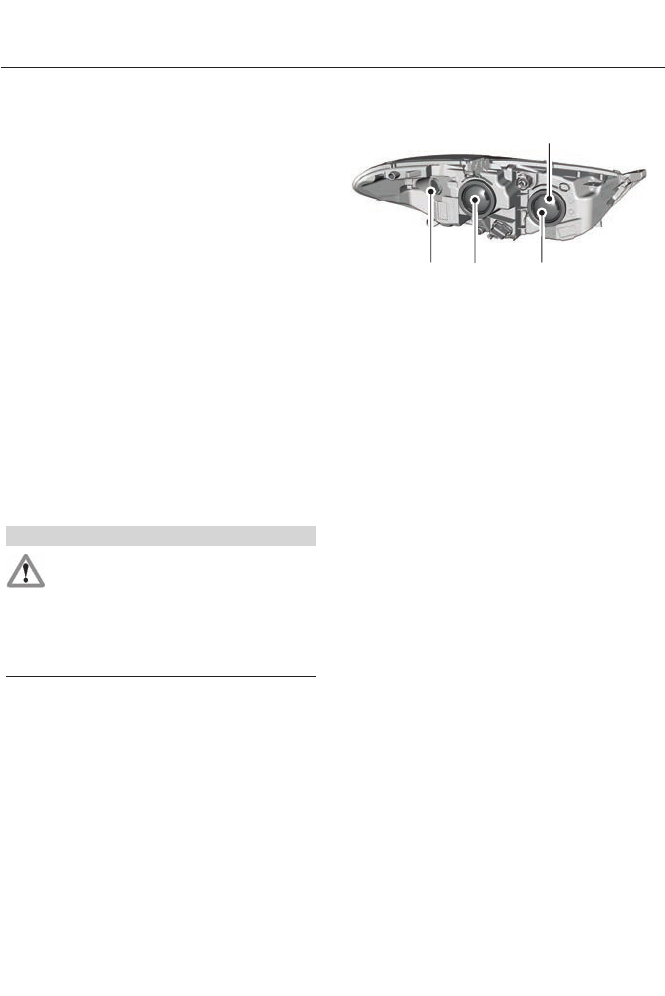
normal condensation occurs, a thin film of
mist can form on the interior of the lens.
The thin mist eventually clears and exits
through the vents during normal operation.
Clearing time may take as long as 48 hours
under dry weather conditions.
Examples of acceptable condensation are:
• Presence of thin mist (no streaks, drip
marks or droplets).
• Fine mist covers less than 50% of the
lens.
Examples of unacceptable moisture
(usually caused by a lamp water leak) are:
• Water puddle inside the lamp.
• Large water droplets, drip marks or
streaks present on the interior of the
lens.
Take your vehicle to a dealer for service if
any of the above conditions of
unacceptable moisture are present.
Replacing the Headlamp Bulbs
WARNING
Handle a halogen headlamp bulb
carefully and keep out of children’s
reach. Grasp the bulb by only its
plastic base and do not touch the glass.
The oil from your hand could cause the
bulb to break the next time the headlamps
are operated.
Note: If the bulb is accidentally touched, it
should be cleaned with rubbing alcohol
before being used.
A
B
C
D
E159753
Headlamp assembly:
A. Side marker lamp bulb
B. High beam headlamp bulb
C. Low beam headlamp bulb
D. Front parking/Turn signal lamp bulb
Replacing the High Beam Headlamp
Bulb
1. Remove the headlamp assembly.
2. Remove the service cap.
3. Disconnect the electrical connector.
4. Turn the bulb counterclockwise and
remove it from the headlamp
assembly.
5. Install the new bulb in reverse order.
Replacing the Low Beam Headlamp
Bulb
1. Remove the headlamp assembly.
2. Remove the service cap.
3. Disconnect the electrical connector.
4. Release the retainer spring and remove
it from the headlamp assembly.
5. Install the new bulb in reverse order.
Replacing the Front Parking/Turn
Signal Lamp Bulb
1. Remove the headlamp assembly.
249
Maintenance
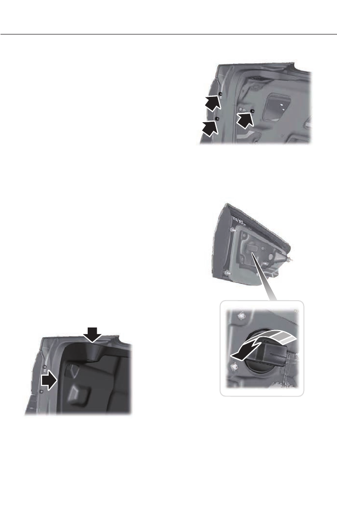
2. Turn the bulb assembly
counterclockwise and remove it from
the headlamp assembly.
3. Separate the bulb from the bulb
socket.
4. Install the new bulb in reverse order.
Replacing the Side Marker Lamp Bulb
1. Remove the headlamp assembly.
2. Remove the service cap.
3. Depress the tabs on the socket and
remove the socket and bulb together.
4. Separate the bulb from the bulb
socket.
5. Install the new bulb in reverse order.
Replacing the Tail, Brake, High-
Mount Brake Lamp, and Turn
Signal Lamp Bulbs
These lamps are designed with LED light
sources. For replacement, see your
authorized dealer.
Replacing a Reverse Lamp Bulb
1. Make sure the lighting control is in the
off position.
2. Open the trunk deck lid.
E145777
3. Remove the push pins and reposition
the inner body side trim.
E145778
4. Remove the three lamp assembly nuts.
5. Gently pull the lamp assembly away
from the vehicle.
E145779
6. Turn the bulb holder counterclockwise
and remove the bulb holder.
250
Maintenance
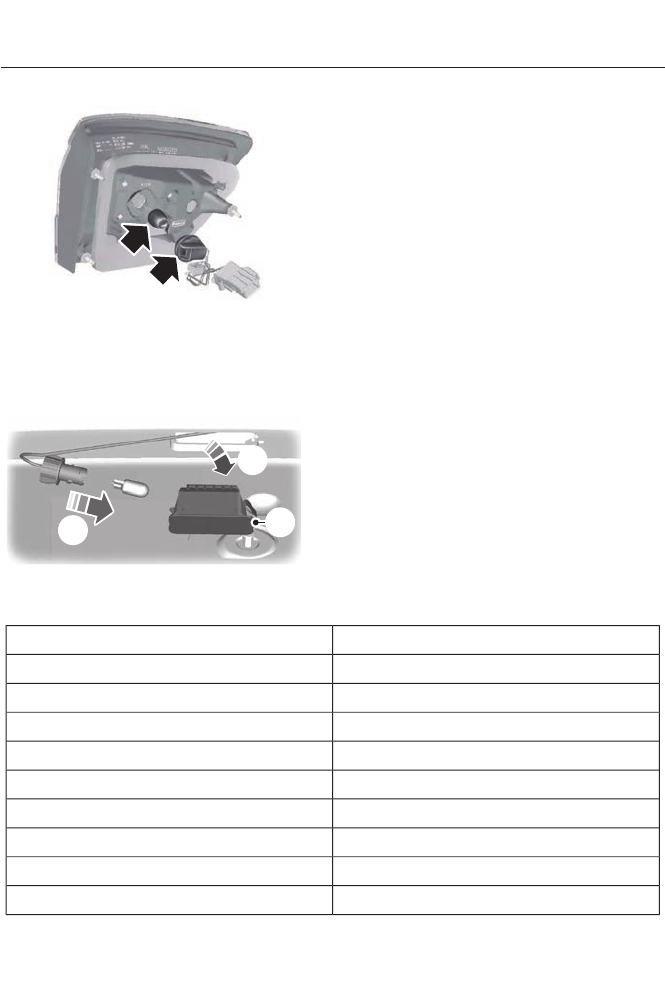
E145780
7. Remove the bulb from the bulb holder.
Install the new bulb in reverse order.
Replacing the License Plate Lamp
Bulb
3
2
1
E72789
1. Carefully release the spring clip.
2. Remove the lamp.
3. Remove the bulb.
Install the new bulb in reverse order.
BULB SPECIFICATION CHART
Replacement bulbs are specified in the
chart below. Headlamp bulbs must be
marked with an authorized “D.O.T.” for
North America to make sure they have the
proper lamp performance, light brightness,
light pattern, and safe visibility. The correct
bulbs will not damage the lamp assembly
or void the lamp assembly warranty and
will provide quality bulb illumination time.
Trade nameFunction
H7LL*Headlamp high beam (Halogen)
H11LL*Headlamp low beam (Halogen)
LED*Side marker lamp - front
W5W*Park lamp - front
PWY24W*Turn lamp - front
H11*Fog lamp - front
LED*Tail and brake lamp - high series
LED*Tail and brake lamp - low series
921Reverse lamp
251
Maintenance

Trade nameFunction
LED*Turn lamp - rear - high series
LED*Turn lamp - rear - low series
LED*Side marker lamp - rear
W5WLicense plate lamp
W5W*Trunk lamp
LED*High-mount brake lamp
LED*Side repeater lamp
LED*Interior lamp
*To replace these bulbs, see your authorized dealer.
To replace all instrument panel bulbs, see your authorized dealer.
252
Maintenance

GENERAL INFORMATION
Your Ford or Lincoln authorized dealer has
many quality products available to clean
your vehicle and protect its finishes.
CLEANING PRODUCTS
For best results, use the following products
or products of equivalent quality:
Motorcraft® Bug and Tar Remover
(ZC-42)
Motorcraft® Custom Bright Metal Cleaner
(ZC-15)
Motorcraft® Detail Wash (ZC-3-A)
Motorcraft® Dusting Cloth (ZC-24)
Motorcraft® Engine Shampoo and
Degreaser (U.S. only) (ZC-20)
Motorcraft® Engine Shampoo (Canada
only) (CXC-66-A)
Motorcraft® Multi-Purpose Cleaner
(Canada only) (CXC-101)
Motorcraft® Premium Glass Cleaner
(Canada only) (CXC-100)
Motorcraft® Premium Quality Windshield
Washer Fluid (Canada only) [CXC-37-(A,
B, D or F)]
Motorcraft® Premium Windshield Washer
Concentrate (U.S. only) (ZC-32-A)
Motorcraft® Professional Strength Carpet
& Upholstery Cleaner (ZC-54)
Motorcraft® Spot and Stain Remover (U.S.
only) (ZC-14)
Motorcraft® Ultra-Clear Spray Glass
Cleaner (ZC-23)
Motorcraft® Vinyl Cleaner (Canada only)
(CXC-93)
Motorcraft® Wheel and Tire Cleaner
(ZC-37-A)
CLEANING THE EXTERIOR
Wash your vehicle regularly with cool or
lukewarm water and a neutral pH
shampoo, such as Motorcraft® Detail
Wash.
• Never use strong household detergents
or soap, such as dish washing or
laundry liquid. These products can
discolor and spot painted surfaces.
• Never wash a vehicle that is “hot to the
touch” or during exposure to strong,
direct sunlight.
• Dry the vehicle with a chamois or soft
terry cloth towel in order to eliminate
water spotting.
• Immediately remove items such as
gasoline, diesel fuel, bird droppings and
insect deposits because they can cause
damage to the vehicle’s paintwork and
trim over time. Use Motorcraft® Bug
and Tar Remover.
• Remove any exterior accessories, such
as antennas, before entering a car
wash.
Note: Suntan lotions and insect repellents
can damage any painted surface; if these
substances come in contact with your
vehicle, wash off as soon as possible.
Exterior Chrome
Note: Never use abrasive materials such as
steel wool or plastic pads as they can
scratch the chrome surface.
Note: Do not use chrome cleaner, metal
cleaner or polish on wheels and wheel
covers
253
Vehicle Care

• Wash the vehicle first, using cool or
lukewarm water and a neutral pH
shampoo, such as Motorcraft® Detail
Wash.
• Use Motorcraft® Custom Bright Metal
Cleaner. Apply the product as you
would a wax to clean bumpers and
other chrome parts; allow the cleaner
to dry for a few minutes, then wipe off
the haze with a clean, dry rag.
• Do not apply cleaning product to hot
surfaces and do not leave cleaning
product on chrome surfaces for a
period of time exceeding that which is
recommended.
• Using other non-recommended
cleaners can result in severe and
permanent cosmetic damage.
Underbody
Flush the complete underside of your
vehicle frequently. Keep body and door
drain holes free from packed dirt.
Cleaning Plastic Exterior Parts
Use only approved products to clean
plastic parts
• For routine cleaning, use Motorcraft®
Detail Wash.
• If tar or grease spots are present, use
Motorcraft® Bug and Tar Remover.
REPAIRING MINOR PAINT
DAMAGE
Your authorized dealer has touch-up paint
to match your vehicle’s color. Take your
color code (printed on a sticker in the
driver’s door jamb) to your authorized
dealer to ensure you get the correct color.
• Remove particles such as bird
droppings, tree sap, insect deposits, tar
spots, road salt and industrial fallout
before repairing paint chips.
• Always read the instructions before
using the products.
WAXING
Regular waxing is necessary to protect your
car's paint from the elements. We
recommend that you wash and wax the
painted surface once or twice a year.
When washing and waxing, park your
vehicle in a shaded area out of direct
sunlight. Always wash your vehicle before
applying wax.
• Use a quality wax that does not contain
abrasives.
• Follow the manufacturer’s instructions
to apply and remove the wax.
• Apply a small amount of wax in a
back-and-forth motion, not in circles.
• Do not allow wax to come in contact
with any non-body (low-gloss black)
colored trim. The wax will discolor or
stain the parts over time.
• Roof racks.
• Bumpers.
• Grained door handles.
• Side mouldings.
• Mirror housings.
• Windshield cowl area.
• Do not apply wax to glass areas.
• After waxing, your car's paint should
feel smooth, and be free of streaks and
smudges.
254
Vehicle Care

CLEANING THE ENGINE
Engines are more efficient when they are
clean because grease and dirt buildup keep
the engine warmer than normal.
When washing:
• Take care when using a power washer
to clean the engine. The high-pressure
fluid could penetrate the sealed parts
and cause damage.
• Do not spray a hot engine with cold
water to avoid cracking the engine
block or other engine components.
• Spray Motorcraft® Engine Shampoo
and Degreaser on all parts that require
cleaning and pressure rinse clean. In
Canada, use Motorcraft® Engine
Shampoo.
• Never wash or rinse the engine while it
is hot or running; water in the running
engine may cause internal damage.
• Never wash or rinse any ignition coil,
spark plug wire or spark plug well, or
the area in and around these locations.
• Cover the battery, power distribution
box, and air filter assembly to prevent
water damage when cleaning the
engine.
CLEANING THE WINDOWS AND
WIPER BLADES
The windows and wiper blades should be
cleaned regularly. If the wipers do not wipe
properly, substances on the vehicle’s glass
or the wiper blades may cause squeaking
or chatter noise from the blades, and
streaking and smearing of the windshield.
To clean these items, follow these tips:
• The windows may be cleaned with a
non-abrasive cleaner such as
Motorcraft® Ultra-Clear Spray Glass
Cleaner.
• The wiper blades can be cleaned with
isopropyl (rubbing) alcohol or
Motorcraft® Premium Windshield
Washer Concentrate in the U.S., or
Premium Quality Windshield Washer
Fluid in Canada. Be sure to replace
wiper blades when they appear worn
or do not function properly.
• Do not use abrasives, as they may
cause scratches
• Do not use fuel, kerosene, or paint
thinner to clean any parts.
If you cannot remove those streaks after
cleaning with the glass cleaner or if the
wipers chatter and move in a jerky motion,
clean the outer surface of the windshield
and the wiper blades using a sponge or
soft cloth with a neutral detergent or
mild-abrasive cleaning solution. After
cleaning, rinse the windshield and wiper
blades with clean water. The windshield
is clean if beads do not form when you
rinse the windshield with water.
Note: Do not use sharp objects, such as a
razor blade, to clean the inside of the rear
window or to remove decals, as it may cause
damage to the rear window defroster’s
heated grid lines.
CLEANING THE INTERIOR
WARNINGS
Do not use cleaning solvents, bleach
or dye on the vehicle’s safety belts,
as these actions may weaken the
belt webbing.
255
Vehicle Care
WARNINGS
On vehicles equipped with
seat-mounted airbags, do not use
chemical solvents or strong
detergents. Such products could
contaminate the side airbag system and
affect performance of the side airbag in a
collision.
For fabric, carpets, cloth seats, safety belts
and seats equipped with side airbags:
• Remove dust and loose dirt with a
vacuum cleaner.
• Remove light stains and soil with
Motorcraft® Professional Strength
Carpet & Upholstery Cleaner.
• If grease or tar is present on the
material, spot-clean the area first with
Motorcraft® Spot and Stain Remover.
In Canada, use Motorcraftt
Multi-Purpose Cleaner.
• If a ring forms on the fabric after spot
cleaning, clean the entire area
immediately (but do not oversaturate)
or the ring will set.
• Do not use household cleaning
products or glass cleaners, which can
stain and discolor the fabric and affect
the flame retardant abilities of the seat
materials.
CLEANING THE INSTRUMENT
PANEL AND INSTRUMENT
CLUSTER LENS
WARNING
Do not use chemical solvents or
strong detergents when cleaning the
steering wheel or instrument panel
to avoid contamination of the airbag
system.
Clean the instrument panel and cluster
lens with a clean, damp, white cotton
cloth, then use a clean and dry white
cotton cloth to dry these areas.
• Avoid cleaners or polishes that increase
the gloss of the upper portion of the
instrument panel. The dull finish in this
area helps protect you from
undesirable windshield reflection.
• Be certain to wash or wipe your hands
clean if you have been in contact with
certain products such as insect
repellent and suntan lotion in order to
avoid possible damage to the interior
painted surfaces.
• Do not use household or glass cleaners
as these may damage the finish of the
instrument panel, interior trim and
cluster lens.
• Do not allow air fresheners and hand
sanitizers to spill onto interior surfaces.
If a spill occurs, wipe off immediately.
Damage may not be covered by your
warranty.
If a staining liquid like coffee or juice has
been spilled on the instrument panel or on
interior trim surfaces, clean as follows:
1. Wipe up spilled liquid using a clean,
white, cotton cloth.
2. Wipe the surface with a damp, clean,
white cotton cloth. For more thorough
cleaning, use a mild soap and water
solution. If the spot cannot be
completely cleaned by this method,
the area may be cleaned using a
commercially available cleaning
product designed for automotive
interiors.
3. If necessary, apply more soap and
water solution or cleaning product to
a clean, white, cotton cloth and press
the cloth onto the soiled area. Allow
this to set at room temperature for 30
minutes.
256
Vehicle Care

4. Remove the soaked cloth and if it is not
soiled badly, use this cloth to clean the
area by using a rubbing motion for 60
seconds.
5. Following this, wipe area dry with a
clean, white, cotton cloth.
CLEANING LEATHER SEATS (IF
EQUIPPED)
For routine cleaning, wipe the surface with
a soft, damp cloth. For more thorough
cleaning, wipe the surface with a mild soap
and water solution. Dry the area with a soft
cloth. In Canada, use Motorcraft® Vinyl
Cleaner.
If the leather cannot be completely
cleaned using a mild soap and water
solution, the leather may be cleaned using
a commercially available leather cleaning
product designed for automotive interiors.
Note: To check for compatibility, first test
any cleaner or stain remover on an
inconspicuous part of the leather.
You should:
• remove dust and loose dirt with a
vacuum cleaner.
• clean spills and stains as quickly as
possible.
• To check for compatibility, first test any
cleaner or stain remover on an
inconspicuous part of the leather.
Do not use the following products as these
may damage the leather:
• oil/petroleum-based leather
conditioners.
• household cleaners.
• alcohol solutions.
• solvents or cleaners intended for
rubber, vinyl and plastics.
CLEANING THE ALLOY
WHEELS
Note: Do not apply a cleaning chemical to
warm or hot wheel rims and covers.
Note: Some automatic car washes may
cause damage to the finish on your wheel
rims and covers.
Note: Industrial-strength or heavy-duty
cleaners in combination with brush agitation
to remove brake dust and dirt, could wear
away the clear coat finish over a period time.
Note: Do not use hydrofluoric acid-based
or high caustic-based wheel cleaners, steel
wool, fuels or strong household detergents.
Note: If you intend parking your vehicle for
an extended period after cleaning the
wheels with a wheel cleaner, drive your
vehicle for a few minutes before doing so.
This will reduce the risk of increased
corrosion of the brake discs.
Alloy wheels and wheel covers are coated
with a clear coat paint finish. To maintain
their condition we recommend that you:
• Clean the wheels weekly, with the
recommended Ford service wheel and
tire cleaner. Apply using
manufacturer's instructions. Use
Motorcraft® Wheel and Tire Cleaner
(ZC-37-A).
• Use a sponge to remove heavy
deposits of dirt and brake dust
accumulation.
• Rinse thoroughly with a strong stream
of water when you have completed the
cleaning process.
• To remove tar and grease, use
Motorcraft® Bug and Tar Remover
(ZC-42).
257
Vehicle Care

VEHICLE STORAGE
If you plan on storing your vehicle for an
extended period of time (30 days or more),
read the following maintenance
recommendations to make sure your
vehicle stays in good operating condition.
All motor vehicles and their components
were engineered and tested for reliable,
regular driving. Long term storage under
various conditions may lead to component
degradation or failure unless specific
precautions are taken to preserve the
components.
General
• Store all vehicles in a dry, ventilated
place.
• Protect from sunlight, if possible.
• If vehicles are stored outside, they
require regular maintenance to protect
against rust and damage.
Body
• Wash vehicle thoroughly to remove
dirt, grease, oil, tar or mud from exterior
surfaces, rear-wheel housing and
underside of front fenders.
• Periodically wash vehicles stored in
exposed locations.
• Touch-up raw or primed metal to
prevent rust
• Cover chrome and stainless steel parts
with a thick coat of auto wax to prevent
discoloration. Re-wax as necessary
when the vehicle is washed.
• Lubricate all hood, door and trunk lid
hinges, and latches with a light grade
oil.
• Cover interior trim to prevent fading.
• Keep all rubber parts free from oil and
solvents.
Engine
• The engine oil and filter should be
changed prior to storage, as used
engine oil contain contaminates that
may cause engine damage.
• Start the engine every 15 days. Run at
fast idle until it reaches normal
operating temperature
• With your foot on the brake, shift
through all the gears while the engine
is running.
Fuel system
• Fill the fuel tank with high-quality fuel
until the first automatic shutoff of the
fuel pump nozzle.
Note: During extended periods of vehicle
storage (30 days or more), fuel may
deteriorate due to oxidation. Add a quality
gas stabilizer product to the vehicle fuel
system whenever actual or expected
storage periods exceed 30 days. Follow the
instructions on the additive label. The
vehicle should then be operated at idle
speed to circulate the additive throughout
the fuel system.
Cooling system
• Protect against freezing temperatures.
• When removing vehicle from storage,
check coolant fluid level. Confirm there
are no cooling system leaks, and fluid
is at the recommended level.
Battery
• Check and recharge as necessary. Keep
connections clean.
• If storing your vehicle for more than 30
days without recharging the battery, it
may be advisable to disconnect the
battery cables to ensure battery charge
is maintained for quick starting.
258
Vehicle Care

Note: If battery cables are disconnected, it
will be necessary to reset memory features.
Brakes
• Make sure brakes and parking brake
are fully released.
Tires
• Maintain recommended air pressure.
Miscellaneous
• Make sure all linkages, cables, levers
and pins under vehicle are covered with
grease to prevent rust.
• Move vehicles at least 25 feet (8
meters) every 15 days to lubricate
working parts and prevent corrosion.
Removing Vehicle From Storage
When your vehicle is ready to come out of
storage, do the following:
• Wash your vehicle to remove any dirt
or grease film build-up on window
surfaces.
• Check windshield wipers for any
deterioration.
• Check under the hood for any foreign
material that may have collected
during storage (mice/squirrel nests).
• Check the exhaust for any foreign
material that may have collected
during storage.
• Check tire pressures and set tire
inflation per the Tire Label.
• Check brake pedal operation. Drive the
vehicle 15 feet (4.5 meters) back and
forth to remove rust build-up.
• Check fluid levels (including coolant,
oil and gas) to make sure there are no
leaks, and fluids are at recommended
levels.
• If the battery was removed, clean the
battery cable ends and inspect.
Contact your authorized dealer if you have
any concerns or issues.
259
Vehicle Care
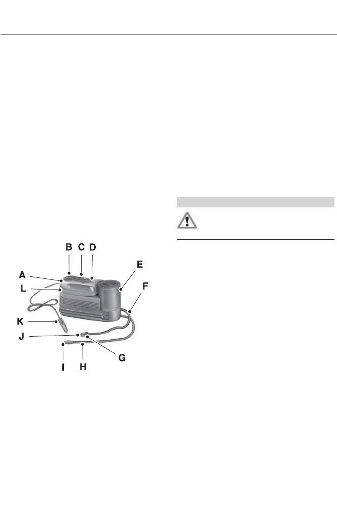
TEMPORARY MOBILITY KIT
Note: The temporary mobility kit sealant
compound in the canister is to be used for
one tire only. See your Ford authorized
dealer for additional replacement sealant
canisters.
The kit is located in the spare tire well in
the trunk. The kit consists of an air
compressor to reinflate the tire and a
sealing compound in a canister that will
effectively seal most punctures caused by
nails or similar objects. This kit will provide
a temporary seal allowing you to drive your
vehicle up to 120 miles (200 kilometers)
at a maximum speed of 50 mph (80
km/h).
E144618
Air compressor (inside)A
Diverter knobB
On/off buttonC
Air pressure gaugeD
Sealant bottle and canisterE
Sealant filling clear tubeF
Sealant tube - tire valve
connector
G
Yellow cap toolH
Air compressor hoseI
Air hose -tire valve connectorJ
Accessory power plugK
Casing/housingL
General Information
WARNING
Failure to follow these guidelines
could result in an increased risk of
loss of vehicle control, injury or death.
Note: Do not use the kit if a tire has become
severely damaged by driving the vehicle with
a tire that has insufficient air pressure. Only
punctured areas located within the tire tread
can be sealed with the kit.
Do not attempt to repair punctures larger
than 1.4 inch (6.4 millimeters) or damage
to the tire's sidewall. The tire may not
completely seal.
Loss of air pressure may adversely affect
tire performance. For this reason:
Note: Do not drive the vehicle above 50
mph (80 km/h).
Note: Do not drive further than 120 miles
(200 kilometers). Drive only to the closest
Ford Motor Company authorized dealer or
tire repair shop to have your tire inspected.
260
Wheels and Tires

• Drive carefully and avoid abrupt
steering maneuvers.
• Periodically monitor tire inflation
pressure in the affected tire; if the tire
is losing pressure, have the vehicle
towed.
• Read the information in the Tips for
Use of the Kit section to make sure safe
operation of the kit and your vehicle.
Tips for Use of the Kit
Read the following list of tips to ensure
safe operation of the kit:
• Before operating the kit, make sure
your vehicle is safely off the road and
away from moving traffic. Turn on the
hazard lights.
• Always set the parking brake to ensure
the vehicle doesn't move unexpectedly.
• Do not remove any foreign objects,
such as nails or screws, from the tire.
• When using the kit, leave the engine
running (only if the vehicle is outdoors
or in a well-ventilated area) so the
compressor doesn't drain the vehicle's
battery.
• Do not allow the compressor to
operate continuously for more than 15
minutes; this will help prevent the
compressor from overheating.
• Never leave the kit unattended when
it is operating.
• Sealant compound contains latex.
Make sure that you use the non-latex
gloves provided to avoid an allergic
reaction.
• Keep the kit away from children.
• Only use the kit when the ambient
temperature is between -22°F (–30°C)
and 158°F (70°C).
• Only use the sealing compound before
the use by date. The use by date is on
the lower right hand corner of the label
located on the sealant canister
(bottle). Check the use by date
regularly and replace the canister after
four years.
• Do not store the kit unsecured inside
the passenger compartment of the
vehicle as it may cause injury during a
sudden stop or crash. Always store the
kit in its original location.
• After sealant use, the tire pressure
monitoring system sensor and valve
stem on the wheel must be replaced
by an authorized Ford dealer.
• When inflating a tire or other objects,
use the black air hose only. Do not use
the transparent hose which is designed
for sealant application only.
• Operating the kit could cause an
electrical disturbance in radio, CD, and
DVD player operation.
What to do when a Tire Is
Punctured
A tire puncture within the tire's tread area
can be repaired in two stages with the kit.
• In the first stage, the tire will be
reinflated with a sealing compound
and air. After the tire has been
reinflated, you will need to drive the
vehicle a short distance (about 4 miles
[6 kilometers]) to distribute the
sealant in the tire.
• In the second stage, you will need to
check the tire pressure and adjust, if
necessary, to the vehicle's tire inflation
pressure.
261
Wheels and Tires
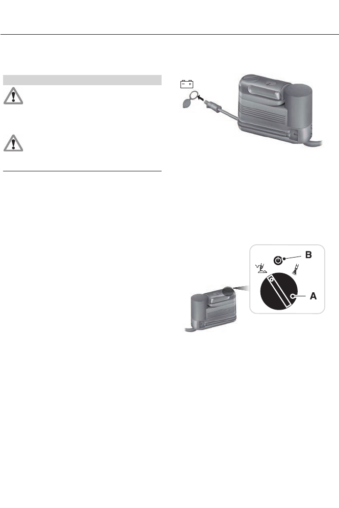
First Stage: Reinflating the Tire
with Sealing Compound and Air
WARNINGS
Do not stand directly over the kit
while inflating the tire. If you notice
any unusual bulges or deformations
in the tire's sidewall during inflation, stop
and call roadside assistance.
If the tire doesn't inflate to the
recommended tire pressure within
15 minutes, stop and call roadside
assistance.
Preparation: Park the vehicle in a safe, level
and secure area, away from moving traffic.
Turn the hazard lights on. Apply the parking
brake and turn the engine off. Inspect the
flat tire for visible damage.
Sealant compound contains latex. To
avoid any allergic reactions, use the
non-latex gloves located in the accessory
box on the underside of the kit housing.
Do not remove any foreign object that has
pierced the tire. If a puncture is located in
the tire sidewall, stop and call roadside
assistance.
1. Remove the valve cap from the tire
valve.
2. Unwrap the clear tube from the
compressor housing.
3. Remove the tube cap and fasten the
metal connector of the tube to the tire
valve, turning clockwise. Make sure the
connection is tightly fastened.
E144619
4. Plug the power cable into the 12-volt
power point in the vehicle.
5. Remove the warning sticker found on
the canister and place it on the top of
the instrument panel or the center of
the dash.
6. Start the engine only if the vehicle is
outdoors or in a well-ventilated area.
E144924
7. Push and turn dial (A)
counterclockwise to the sealant
position. Turn on the kit by pressing the
on/off button (B).
262
Wheels and Tires
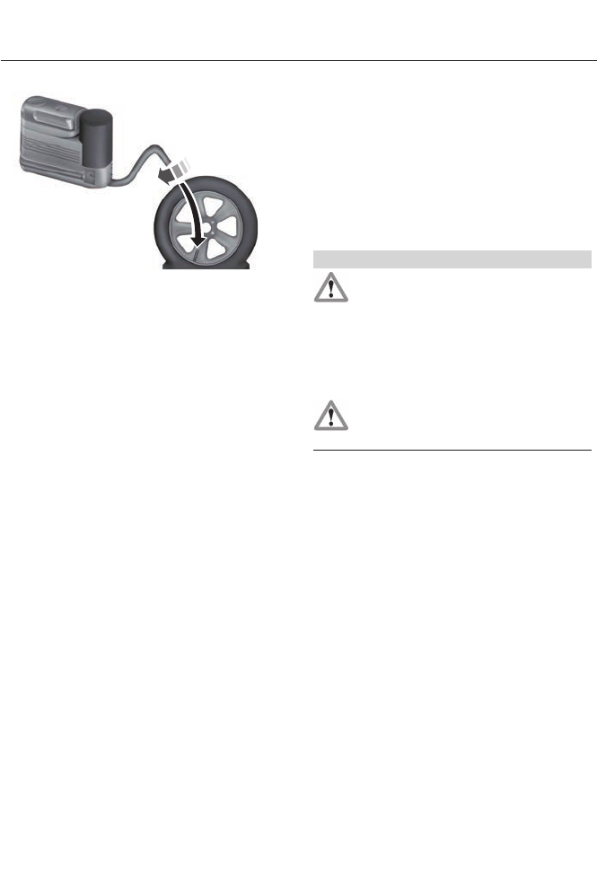
E144621
8. Inflate the tire to the pressure listed on
the tire label located on the driver's
door or the door jamb area. When the
sealing compound is first added into
the tire, the air pressure gauge reading
on the compressor unit may indicate a
higher value; this is normal and should
be no reason for concern. The pressure
will drop after about 30 seconds of
operation. The tire pressure has to be
checked with the compressor in the
OFF position to get the correct tire
pressure reading.
9. When the recommended tire pressure
is reached, turn off the kit by pressing
the on button; disconnect the kit from
the tire valve and the power point.
Re-install the valve cap on the tire
valve, place the tube cap on the metal
connector, and return the kit to the
stowage area
10. Immediately and cautiously, drive the
vehicle 4 miles (6 kilometers) to
distribute the sealant evenly inside
the tire. Do not exceed 50 mph (80
km/h).
11. After 4 miles (6 kilometers), stop and
check the tire pressure. See Second
stage: Checking tire pressure.
Note: If you experience any unusual
vibration, ride disturbance or noise while
driving, reduce your speed until you can
safely pull off to the side of the road to call
for roadside assistance. Note: Do not
proceed to the second stage of this
operation.
Second Stage: Checking Tire
Pressure
WARNINGS
If you are proceeding from the First
stage: Re–inflating the tire with
sealing compound and air section
and have injected sealant in the tire and
the pressure is below 20 psi (1.4 bar), stop
and call roadside assistance. If tire
pressure is above 20 psi (1.4 bar), continue
to the next step.
The power plug may get hot after use
and should be handled carefully
while unplugging.
Check the air pressure of your tires as
follows:
1. Remove the valve cap from the tire
valve.
2. Unhook the black hose from the side
of the compressor and fasten firmly on
the valve stem by turning clockwise.
3. Push and turn the dial clockwise to the
air position. Turn on the kit by pressing
the on button.
263
Wheels and Tires
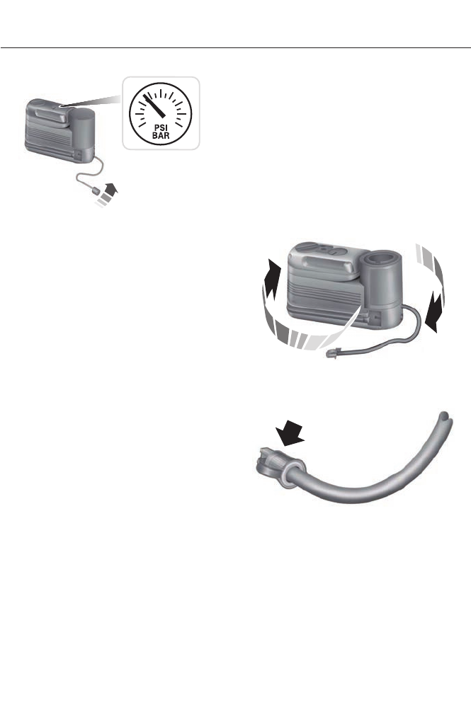
E144622
4. Adjust the tire to the recommended
inflation pressure from the tire label
located on the driver's door or door
jamb area. The tire pressure has to be
checked with the compressor in the
OFF position to get the correct tire
pressure reading.
5. Turn the compressor off by pressing
the on/off button.
6. Unplug the hoses, re-install the valve
cap on the tire and return the kit to the
stowage area.
What to do after the Tire has been
Sealed
After using the kit to seal your tire, you will
need to replace the sealant canister and
clear tube (hose). Sealing compound and
spare parts can be obtained and replaced
at an authorized Ford Motor Company
dealership or tire dealer. Empty sealant
bottles may be disposed of at home;
however, liquid residue from the sealing
compound should be disposed by your
local Ford Motor Company dealership or
tire dealer, or in accordance with local
waste disposal regulations.
Note: After the sealing compound has been
used, the maximum vehicle speed is 50 mph
(80 km/h) and the maximum driving
distance is 120 miles (200 kilometers). The
sealed tire should be inspected immediately.
Note: After sealant use, the tire pressure
monitoring system sensor and valve stem
on the wheel must be replaced by an
authorized Ford dealer.
You can check the tire pressure any time
within the 120 miles (200 kilometers) by
performing the procedure from Second
stage: Checking tire pressure listed
previously.
Removal of the sealant canister from
the kit
E144623
1. Unwrap the clear tube from the
compressor housing.
E144624
2. Locate the yellow cap at the end of the
clear tube.
264
Wheels and Tires
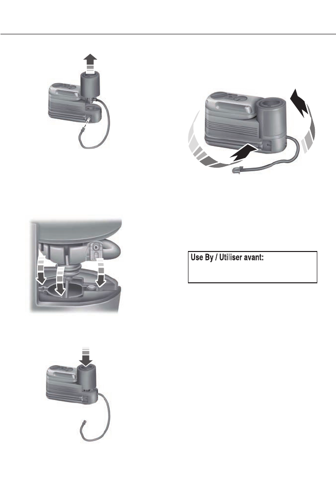
E144625
3. Using the yellow cap tool, press the tab
located on the kit compressor housing
while pulling up on the sealant canister.
Installation of the sealant canister to
the kit
E144626
1. Align the sealant canister with the kit
housing.
E161567
2. Once aligned, seat the sealant canister
by lightly pushing down until you hear
an audible click.
E144628
3. Wrap the clear tube around the
compressor housing.
Note: If you experience any difficulties with
the removal or installation of the sealant
canister, consult your Ford Motor Company
authorized dealer for assistance.
E144629
Be sure to check the sealant compound's
use by date regularly. The use by date is
on the lower right hand corner of the label
located on the sealant canister (bottle).
The sealant canister should be replaced
after four years.
265
Wheels and Tires
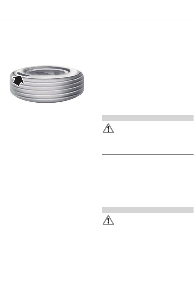
TIRE CARE
Information About Uniform Tire
Quality Grading
E142542
Tire Quality Grades apply to new
pneumatic passenger car tires. The Quality
grades can be found where applicable on
the tire sidewall between tread shoulder
and maximum section width. For example:
Treadwear 200 Traction AA
Temperature A.
These Tire Quality Grades are determined
by standards that the United States
Department of Transportation has set.
Tire Quality Grades apply to new
pneumatic passenger car tires. They do
not apply to deep tread, winter-type snow
tires, space-saver or temporary use spare
tires, light truck or LT type tires, tires with
nominal rim diameters of 10 to 12 inches
or limited production tires as defined in
Title 49 Code of Federal Regulations Part
575.104 (c)(2).
U.S. Department of Transportation Tire
quality grades: The U.S. Department of
Transportation requires Ford Motor
Company to give you the following
information about tire grades exactly as
the government has written it.
Treadwear
The treadwear grade is a comparative
rating based on the wear rate of the tire
when tested under controlled conditions
on a specified government test course. For
example, a tire graded 150 would wear 1½
times as well on the government course
as a tire graded 100. The relative
performance of tires depends upon the
actual conditions of their use, however,
and may depart significantly from the norm
due to variations in driving habits, service
practices, and differences in road
characteristics and climate.
Traction AA A B C
WARNING
The traction grade assigned to this
tire is based on straight-ahead
braking traction tests, and does not
include acceleration, cornering,
hydroplaning or peak traction
characteristics.
The traction grades, from highest to lowest
are AA, A, B, and C. The grades represent
the tire’s ability to stop on wet pavement
as measured under controlled conditions
on specified government test surfaces of
asphalt and concrete. A tire marked C may
have poor traction performance.
Temperature A B C
WARNING
The temperature grade for this tire
is established for a tire that is
properly inflated and not overloaded.
Excessive speed, underinflation, or
excessive loading, either separately or in
combination, can cause heat buildup and
possible tire failure.
266
Wheels and Tires

The temperature grades are A (the
highest), B and C, representing the tire’s
resistance to the generation of heat and
its ability to dissipate heat when tested
under controlled conditions on a specified
indoor laboratory test wheel. Sustained
high temperature can cause the material
of the tire to degenerate and reduce tire
life, and excessive temperature can lead
to sudden tire failure. The grade C
corresponds to a level of performance
which all passenger car tires must meet
under the Federal Motor Vehicle Safety
Standard No. 139. Grades B and A
represent higher levels of performance on
the laboratory test wheel than the
minimum required by law.
Glossary of Tire Terminology
* Tire label: A label showing the
OE (Original Equipment) tire sizes,
recommended inflation pressure
and the maximum weight the
vehicle can carry.
*Tire Identification Number
(TIN): A number on the sidewall
of each tire providing information
about the tire brand and
manufacturing plant, tire size and
date of manufacture. Also referred
to as DOT code.
*Inflation pressure: A measure
of the amount of air in a tire.
*Standard load: A class of
P-metric or Metric tires designed
to carry a maximum load at 35 psi
[37 psi (2.5 bar) for Metric tires].
Increasing the inflation pressure
beyond this pressure will not
increase the tire’s load carrying
capability.
*Extra load: A class of P-metric
or Metric tires designed to carry a
heavier maximum load at 41 psi
[43 psi (2.9 bar) for Metric tires].
Increasing the inflation pressure
beyond this pressure will not
increase the tire’s load carrying
capability.
*kPa: Kilopascal, a metric unit of
air pressure.
*PSI: Pounds per square inch, a
standard unit of air pressure.
*Cold tire pressure: The tire
pressure when the vehicle has
been stationary and out of direct
sunlight for an hour or more and
prior to the vehicle being driven for
1 mile (1.6 km).
267
Wheels and Tires

*Recommended inflation
pressure: The cold inflation
pressure found on the Safety
Compliance Certification Label
(affixed to either the door hinge
pillar, door-latch post, or the door
edge that meets the door-latch
post, next to the driver's seating
position), or Tire Label located on
the B-Pillar or the edge of the
driver’s door.
*B-pillar: The structural member
at the side of the vehicle behind
the front door
* Bead area of the tire: Area of
the tire next to the rim.
*Sidewall of the tire: Area
between the bead area and the
tread.
*Tread area of the tire: Area of
the perimeter of the tire that
contacts the road when mounted
on the vehicle.
*Rim: The metal support (wheel)
for a tire or a tire and tube
assembly upon which the tire
beads are seated.
Information Contained on the Tire
Sidewall
Both U.S. and Canada Federal
regulations require tire
manufacturers to place
standardized information on the
sidewall of all tires. This
information identifies and
describes the fundamental
characteristics of the tire and also
provides a U.S. DOT Tire
Identification Number for safety
standard certification and in case
of a recall.
Information on P Type Tires
H
I
J
K
L
M
A
B
CDEFG
E142543
P215/65R15 95H is an example of
a tire size, load index and speed
rating. The definitions of these
items are listed below. (Note that
the tire size, load index and speed
rating for your vehicle may be
different from this example.)
268
Wheels and Tires

A. P: Indicates a tire, designated
by the Tire and Rim Association,
that may be used for service on
cars, sport utility vehicles,
minivans and light trucks. Note: If
your tire size does not begin with
a letter this may mean it is
designated by either the European
Tire and Rim Technical
Organization or the Japan Tire
Manufacturing Association.
B. 215: Indicates the nominal
width of the tire in millimeters
from sidewall edge to sidewall
edge. In general, the larger the
number, the wider the tire.
C. 65: Indicates the aspect ratio
which gives the tire's ratio of
height to width.
D. R: Indicates a radial type tire.
E. 15: Indicates the wheel or rim
diameter in inches. If you change
your wheel size, you will have to
purchase new tires to match the
new wheel diameter.
F. 95: Indicates the tire's load
index. It is an index that relates to
how much weight a tire can carry.
You may find this information in
your owner’s manual. If not,
contact a local tire dealer.
Note: You may not find this information on
all tires because it is not required by federal
law.
G. H: Indicates the tire's speed
rating. The speed rating denotes
the speed at which a tire is
designed to be driven for extended
periods of time under a standard
condition of load and inflation
pressure. The tires on your vehicle
may operate at different
conditions for load and inflation
pressure. These speed ratings may
need to be adjusted for the
difference in conditions. The
ratings range from 81 mph (130
km/h) to 186 mph (299 km/h).
These ratings are listed in the
following chart.
Note: You may not find this information on
all tires because it is not required by federal
law.
mph ( km/h)Letter rating
81 mph (130 km/h)M
87 mph (140 km/h)N
99 mph (159 km/h)Q
106 mph (171 km/h)R
112 mph (180 km/h)S
118 mph (190 km/h)T
124 mph (200 km/h)U
130 mph (210 km/h)H
149 mph (240 km/h)V
269
Wheels and Tires

mph ( km/h)Letter rating
168 mph (270 km/h)W
186 mph (299 km/h)Y
Note: For tires with a maximum speed
capability over 149 mph (240 km/h), tire
manufacturers sometimes use the letters
ZR. For those with a maximum speed
capability over 186 mph (299 km/h), tire
manufacturers always use the letters ZR.
H. U.S. DOT Tire Identification
Number (TIN): This begins with
the letters DOT and indicates that
the tire meets all federal
standards. The next two numbers
or letters are the plant code
designating where it was
manufactured, the next two are
the tire size code and the last four
numbers represent the week and
year the tire was built. For
example, the numbers 317 mean
the 31st week of 1997. After 2000
the numbers go to four digits. For
example, 2501 means the 25th
week of 2001. The numbers in
between are identification codes
used for traceability. This
information is used to contact
customers if a tire defect requires
a recall.
I. M+S or M/S: Mud and Snow, or
AT: All Terrain, or
AS: All Season.
J. Tire Ply Composition and
Material Used: Indicates the
number of plies or the number of
layers of rubber-coated fabric in
the tire tread and sidewall. Tire
manufacturers also must indicate
the ply materials in the tire and the
sidewall, which include steel,
nylon, polyester, and others.
K. Maximum Load: Indicates the
maximum load in kilograms and
pounds that can be carried by the
tire. See the Safety Compliance
Certification Label (affixed to
either the door hinge pillar,
door-latch post, or the door edge
that meets the door-latch post,
next to the driver's seating
position), for the correct tire
pressure for your vehicle.
L. Treadwear, Traction and
Temperature Grades:
* Treadwear The treadwear
grade is a comparative rating
based on the wear rate of the tire
when tested under controlled
conditions on a specified
government test course. For
example, a tire graded 150 would
wear one and one-half times as
well on the government course as
a tire graded 100.
270
Wheels and Tires

*Traction: The traction grades,
from highest to lowest are AA, A,
B, and C. The grades represent the
tire's ability to stop on wet
pavement as measured under
controlled conditions on specified
government test surfaces of
asphalt and concrete. A tire
marked C may have poor traction
performance.
* Temperature: The temperature
grades are A (the highest), B and
C, representing the tire's
resistance to the generation of
heat and its ability to dissipate
heat when tested under controlled
conditions on a specified indoor
laboratory test wheel.
M. Maximum Inflation
Pressure: Indicates the tire
manufacturers' maximum
permissible pressure or the
pressure at which the maximum
load can be carried by the tire. This
pressure is normally higher than
the vehicle manufacturer's
recommended cold inflation
pressure which can be found on
the Safety Compliance
Certification Label (affixed to
either the door hinge pillar,
door-latch post, or the door edge
that meets the door-latch post,
next to the driver's seating
position), or Tire Label which is
located on the B-Pillar or the edge
of the driver’s door. The cold
inflation pressure should never be
set lower than the recommended
pressure on the vehicle label.
The tire suppliers may have
additional markings, notes or
warnings such as standard load
or radial tubeless.
Additional Information Contained on
the Tire Sidewall for LT Type Tires
Note: Tire Quality Grades do not apply to
this type of tire.
A
BC
B
D
E142544
LT type tires have some additional
information beyond those of P
type tires; these differences are
described below.
271
Wheels and Tires
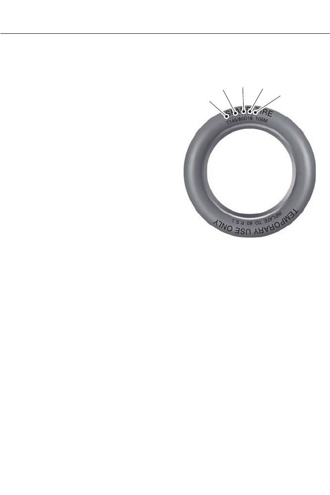
A. LT: Indicates a tire, designated
by the Tire and Rim Association
(T&RA), that is intended for
service on light trucks.
B. Load Range and Load
Inflation Limits: Indicates the
tire's load-carrying capabilities
and its inflation limits.
C. Maximum Load Dual lb (kg)
at psi (kPa) cold: Indicates the
maximum load and tire pressure
when the tire is used as a dual;
defined as four tires on the rear
axle (a total of six or more tires on
the vehicle).
D. Maximum Load Single lb
(kg) at psi (kPa) cold: Indicates
the maximum load and tire
pressure when the tire is used as
a single; defined as two tires
(total) on the rear axle.
Information on T Type Tires
T145/80D16 is an example of a
tire size.
Note: The temporary tire size for your
vehicle may be different from this example.
Tire Quality Grades do not apply to this type
of tire.
A
BCDE
E142545
T type tires have some additional
information beyond those of P
type tires; these differences are
described below:
A. T: Indicates a type of tire,
designated by the Tire and Rim
Association, that is intended for
temporary service on cars,
sport-utility vehicles, minivans and
light trucks.
B. 145: Indicates the nominal
width of the tire in millimeters
from sidewall edge to sidewall
edge. In general, the larger the
number, the wider the tire.
272
Wheels and Tires

C. 80: Indicates the aspect ratio
which gives the tire's ratio of
height to width. Numbers of 70 or
lower indicate a short sidewall.
D. D: Indicates a diagonal type tire.
R: Indicates a radial type tire.
E. 16: Indicates the wheel or rim
diameter in inches. If you change
your wheel size, you will have to
purchase new tires to match the
new wheel diameter.
Location of the Tire Label
You will find a Tire Label
containing tire inflation pressure
by tire size and other important
information located on the B-Pillar
or the edge of the driver’s door.
Inflating Your Tires
Safe operation of your vehicle
requires that your tires are
properly inflated. Remember that
a tire can lose up to half of its air
pressure without appearing flat.
Every day before you drive, check
your tires. If one looks lower than
the others, use a tire gauge to
check pressure of all tires and
adjust if required.
At least once a month and before
long trips, inspect each tire and
check the tire pressure with a tire
gauge (including spare, if
equipped). Inflate all tires to the
inflation pressure recommended
by Ford Motor Company.
You are strongly urged to buy a
reliable tire pressure gauge, as
automatic service station gauges
may be inaccurate. Ford
recommends the use of a digital
or dial-type tire pressure gauge
rather than a stick-type tire
pressure gauge.
Use the recommended cold
inflation pressure for optimum tire
performance and wear.
Under-inflation or over-inflation
may cause uneven treadwear
patterns
WARNING
Under-inflation is the most common
cause of tire failures and may result
in severe tire cracking, tread
separation or blowout, with unexpected
loss of vehicle control and increased risk
of injury. Under-inflation increases sidewall
flexing and rolling resistance, resulting in
heat buildup and internal damage to the
tire. It also may result in unnecessary tire
stress, irregular wear, loss of vehicle
control and accidents. A tire can lose up
to half of its air pressure and not appear
to be flat!
273
Wheels and Tires

Always inflate your tires to the
Ford recommended inflation
pressure even if it is less than the
maximum inflation pressure
information found on the tire. The
Ford recommended tire inflation
pressure is found on the Safety
Compliance Certification Label
(affixed to either the door hinge
pillar, door-latch post, or the door
edge that meets the door-latch
post, next to the driver's seating
position), or Tire Label which is
located on the B-Pillar or the edge
of the driver’s door. Failure to
follow the tire pressure
recommendations can cause
uneven treadwear patterns and
adversely affect the way your
vehicle handles
Maximum Inflation Pressure is
the tire manufacturer's maximum
permissible pressure and the
pressure at which the maximum
load can be carried by the tire. This
pressure is normally higher than
the manufacturer’s recommended
cold inflation pressure which can
be found on the Safety
Compliance Certification Label
(affixed to either the door hinge
pillar, door-latch post, or the door
edge that meets the door-latch
post, next to the driver's seating
position), or Tire Label which is
located on the B-Pillar or the edge
of the driver’s door. The cold
inflation pressure should never be
set lower than the recommended
pressure on the Safety
Compliance Certification Label or
Tire Label.
When weather temperature
changes occur, tire inflation
pressures also change. A 10°F
(6°C) temperature drop can
cause a corresponding drop of 1
psi (7 kPa) in inflation pressure.
Check your tire pressures
frequently and adjust them to the
proper pressure which can be
found on the Safety Compliance
Certification Label or Tire Label.
To check the pressure in your
tire(s):
1. Make sure the tires are cool,
meaning they are not hot from
driving even a mile.
Note: If you are checking tire pressure when
the tire is hot, (for example, driven more
than 1 mile [1.6 kilometers]), never bleed or
reduce air pressure. The tires are hot from
driving and it is normal for pressures to
increase above recommended cold
pressures. A hot tire at or below
recommended cold inflation pressure could
be significantly under-inflated.
Note: If you have to drive a distance to get
air for your tire(s), check and record the tire
pressure first and add the appropriate air
pressure when you get to the pump. It is
normal for tires to heat up and the air
pressure inside to go up as you drive.
274
Wheels and Tires

2. Remove the cap from the valve
on one tire, then firmly press the
tire gauge onto the valve and
measure the pressure.
3. Add enough air to reach the
recommended air pressure.
Note: If you overfill the tire, release air by
pressing on the metal stem in the center of
the valve. Then recheck the pressure with
your tire gauge.
4. Replace the valve cap.
5. Repeat this procedure for each
tire, including the spare.
Note: Some spare tires operate at a higher
inflation pressure than the other tires. For T
type mini-spare tires, see the Dissimilar
spare wheel and tire assembly information
for a description. Store and maintain at 60
psi (4.15 bar). For full-size and dissimilar
spare tires, see the Dissimilar spare wheel
and tire assembly information for a
description. Store and maintain at the higher
of the front and rear inflation pressure as
shown on the Tire Label.
6. Visually inspect the tires to
make sure there are no nails or
other objects embedded that
could poke a hole in the tire and
cause an air leak.
7. Check the sidewalls to make
sure there are no gouges, cuts or
bulges.
Inspecting Your Tires and Wheel Valve
Stems
Periodically inspect the tire treads
for uneven or excessive wear and
remove objects such as stones,
nails or glass that may be wedged
in the tread grooves. Check the tire
and valve stems for holes, cracks,
or cuts that may permit air
leakage and repair or replace the
tire and replace the valve stem.
Inspect the tire sidewalls for
cracking, cuts, bruises and other
signs of damage or excessive
wear. If internal damage to the tire
is suspected, have the tire
demounted and inspected in case
it needs to be repaired or replaced.
For your safety, tires that are
damaged or show signs of
excessive wear should not be used
because they are more likely to
blow out or fail.
Improper or inadequate vehicle
maintenance can cause tires to
wear abnormally. Inspect all your
tires, including the spare,
frequently, and replace them if
one or more of the following
conditions exist:
275
Wheels and Tires
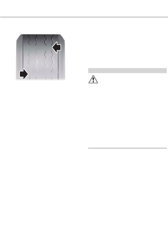
Tire Wear
E142546
When the tread is worn down to
one sixteenth of an inch (2
millimeters), tires must be
replaced to help prevent your
vehicle from skidding and
hydroplaning. Built-in treadwear
indicators, or wear bars, which
look like narrow strips of smooth
rubber across the tread will
appear on the tire when the tread
is worn down to one sixteenth of
an inch (2 millimeters)
When the tire tread wears down
to the same height as these wear
bars, the tire is worn out and must
be replaced.
Damage
Periodically inspect the tire treads
and sidewalls for damage (such
as bulges in the tread or sidewalls,
cracks in the tread groove and
separation in the tread or
sidewall). If damage is observed
or suspected have the tire
inspected by a tire professional.
Tires can be damaged during
off-road use, so inspection after
off-road use is also
recommended.
Age
WARNING
Tires degrade over time depending
on many factors such as weather,
storage conditions, and conditions
of use (load, speed, inflation pressure) the
tires experience throughout their lives.
In general, tires should be replaced after
six years regardless of tread wear.
However, heat caused by hot climates or
frequent high loading conditions can
accelerate the aging process and may
require tires to be replaced more
frequently.
You should replace your spare tire when
you replace the road tires or after six years
due to aging even if it has not been used.
U.S. DOT Tire Identification Number
(TIN)
Both United States and Canada
Federal regulations require tire
manufacturers to place
standardized information on the
sidewall of all tires. This
information identifies and
describes the fundamental
characteristics of the tire and also
provides a U.S. DOT Tire
Identification Number for safety
standard certification and in case
of a recall.
276
Wheels and Tires
This begins with the letters DOT
and indicates that the tire meets
all federal standards. The next
two numbers or letters are the
plant code designating where it
was manufactured, the next two
are the tire size code and the last
four numbers represent the week
and year the tire was built. For
example, the numbers 317 mean
the 31st week of 1997. After 2000
the numbers go to four digits. For
example, 2501 means the 25th
week of 2001. The numbers in
between are identification codes
used for traceability. This
information is used to contact
customers if a tire defect requires
a recall.
Tire Replacement Requirements
Your vehicle is equipped with tires
designed to provide a safe ride
and handling capability.
WARNINGS
Only use replacement tires and
wheels that are the same size, load
index, speed rating and type (such
as P-metric versus LT-metric or all-season
versus all-terrain) as those originally
provided by Ford. The recommended tire
and wheel size may be found on either the
Safety Compliance Certification Label
(affixed to either the door hinge pillar,
door-latch post, or the door edge that
meets the door-latch post, next to the
driver's seating position), or the Tire Label
which is located on the B-Pillar or edge of
the driver’s door. If this information is not
found on these labels then you should
contact your authorized dealer as soon as
WARNINGS
possible. Use of any tire or wheel not
recommended by Ford can affect the
safety and performance of your vehicle,
which could result in an increased risk of
loss of vehicle control, vehicle rollover,
personal injury and death. Additionally the
use of non-recommended tires and wheels
could cause steering, suspension, axle,
transfer case or power transfer unit failure.
If you have questions regarding tire
replacement, contact your authorized
dealer as soon as possible.
To reduce the risk of serious injury
when mounting replacement tires
and wheels, you should not exceed
the maximum pressure indicated on the
sidewall of the tire to set the beads without
additional precautions listed below. If the
beads do not seat at the maximum
pressure indicated, re-lubricate and try
again
When inflating the tire for mounting
pressures up to 20 psi (1.38 bar) greater
than the maximum pressure on the tire
sidewall, the following precautions must
be taken to protect the person mounting
the tire:
1. Make sure that you have the correct tire
and wheel size.
2. Lubricate the tire bead and wheel bead
seat area again.
3. Stand at a minimum of 12 feet (3.66
meters) away from the wheel and tire
assembly.
4. Use both eye and ear protection.
For a mounting pressure more than 20 psi
(1.38 bar) greater than the maximum
pressure, a Ford dealer or other tire service
professional should do the mounting.
277
Wheels and Tires

WARNINGS
Always inflate steel carcass tires with a
remote air fill with the person inflating
standing at a minimum of 12 feet (3.66
meters) away from the wheel and tire
assembly
Important: Remember to replace
the wheel valve stems when the
road tires are replaced on your
vehicle
It is recommended that the two
front tires or two rear tires
generally be replaced as a pair.
The tire pressure sensors mounted
in the wheels (originally installed
on your vehicle) are not designed
to be used in aftermarket wheels.
The use of wheels or tires not
recommended by Ford Motor
Company may affect the
operation of your tire pressure
monitoring system.
If the TPMS indicator is flashing,
your TPMS is malfunctioning. Your
replacement tire might be
incompatible with your TPMS, or
some component of the TPMS
may be damaged.
Safety Practices
WARNINGS
If your vehicle is stuck in snow, mud,
sand, etc., do not rapidly spin the
tires; spinning the tires can tear the
tire and cause an explosion. A tire can
explode in as little as three to five seconds.
WARNINGS
Do not spin the wheels at over 35
mph (56 km/h). The tires may fail
and injure a passenger or bystander.
Driving habits have a great deal to do
with your tire mileage and safety.
*Observe posted speed limits
*Avoid fast starts, stops and turns
*Avoid potholes and objects on
the road
*Do not run over curbs or hit the
tire against a curb when parking
Highway Hazards
No matter how carefully you drive
there’s always the possibility that
you may eventually have a flat tire
on the highway. Drive slowly to the
closest safe area out of traffic.
This may further damage the flat
tire, but your safety is more
important.
If you feel a sudden vibration or
ride disturbance while driving, or
you suspect your tire or vehicle
has been damaged, immediately
reduce your speed. Drive with
caution until you can safely pull
off the road. Stop and inspect the
tires for damage. If a tire is
under-inflated or damaged,
deflate it, remove wheel and
278
Wheels and Tires
replace it with your spare tire and
wheel. If you cannot detect a
cause, have the vehicle towed to
the nearest repair facility or tire
dealer to have the vehicle
inspected.
Tire and Wheel Alignment
A bad jolt from hitting a curb or
pothole can cause the front end
of your vehicle to become
misaligned or cause damage to
your tires. If your vehicle seems to
pull to one side when you’re
driving, the wheels may be out of
alignment. Have an authorized
dealer check the wheel alignment
periodically.
Wheel misalignment in the front
or the rear can cause uneven and
rapid treadwear of your tires and
should be corrected by an
authorized dealer. Front-wheel
drive vehicles and those with an
independent rear suspension (if
equipped) may require alignment
of all four wheels.
The tires should also be balanced
periodically. An unbalanced tire
and wheel assembly may result in
irregular tire wear.
Tire Rotation
Note: If your tires show uneven wear ask
an authorized dealer to check for and correct
any wheel misalignment, tire imbalance or
mechanical problem involved before tire
rotation.
Note: Your vehicle may be equipped with
a dissimilar spare wheel and tire assembly.
A dissimilar spare wheel and tire assembly
is defined as a spare wheel and tire
assembly that is different in brand, size or
appearance from the road tires and wheels.
If you have a dissimilar spare wheel and tire
assembly it is intended for temporary use
only and should not be used in a tire
rotation.
Note: After having your tires rotated,
inflation pressure must be checked and
adjusted to the vehicle requirements.
Rotating your tires at the
recommended interval (as
indicated in the Scheduled
Maintenance chapter) will help
your tires wear more evenly,
providing better tire performance
and longer tire life.
Front-wheel drive and all-wheel
vehicles (front tires on the left side
of the diagram)
E142547
All vehicles with directional tires
(front tires on the left side of the
diagram)
279
Wheels and Tires
E147237
Sometimes irregular tire wear can
be corrected by rotating the tires.
Summer Tires
Your Ford vehicle may be
equipped with summer tires to
provide superior performance on
wet and dry roads. Summer tires
do not have the Mud and Snow
(M+S or M/S) tire traction rating
on the tire side wall. Since
summer tires do not have the
same traction performance as
All-season or Snow tires, Ford
does not recommend using
summer tires when temperatures
drop to approximately 40°F (5°C)
or below (depending on tire wear
and environmental conditions) or
in snow and ice conditions. Like
any tire, summer tire performance
is affected by tire wear and
environmental conditions. If you
must drive in those conditions,
Ford recommends using Mud and
Snow (M+S, M/S), All-season or
Snow tires.
TIRE PRESSURE MONITORING
SYSTEM
WARNING
The tire pressure monitoring system
is not a substitute for manually
checking tire pressure. The tire
pressure should be checked periodically
(at least monthly) using a tire gauge. See
Inflating Your Tires in this chapter. Failure
to properly maintain your tire pressure
could increase the risk of tire failure, loss
of control, vehicle rollover and personal
injury.
Each tire, including the spare (if
provided), should be checked
monthly when cold and inflated
to the inflation pressure
recommended by the vehicle manufacturer
on the vehicle placard or tire inflation
pressure label. (If your vehicle has tires of
a different size than the size indicated on
the vehicle placard or tire inflation pressure
label, you should determine the proper tire
inflation pressure for those tires.)
As an added safety feature, your vehicle
has been equipped with a tire pressure
monitoring system that illuminates a low
tire pressure telltale when one or more of
your tires is significantly under-inflated.
Accordingly, when the low tire pressure
telltale illuminates, you should stop and
check your tires as soon as possible, and
inflate them to the proper pressure. Driving
on a significantly under-inflated tire causes
the tire to overheat and can lead to tire
failure. Under-inflation also reduces fuel
efficiency and tire tread life, and may affect
the vehicle’s handling and stopping ability.
280
Wheels and Tires
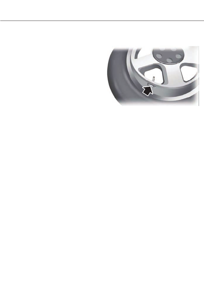
Please note that the tire pressure
monitoring system is not a substitute for
proper tire maintenance. It is the driver’s
responsibility to maintain correct tire
pressure, even if under-inflation has not
reached the level to trigger illumination of
the tire pressure monitoring system low
tire pressure telltale.
Your vehicle has also been equipped with
a tire pressure monitoring system
malfunction indicator to indicate when the
system is not operating properly. The
malfunction indicator is combined with the
low tire pressure telltale. When the system
detects a malfunction, the telltale will
flash for approximately one minute and
then remain continuously illuminated. This
sequence will continue upon subsequent
vehicle start-ups as long as the
malfunction exists.
When the malfunction indicator is
illuminated, the system may not be able
to detect or signal low tire pressure as
intended. System malfunctions may occur
for a variety of reasons, including the
installation of replacement or alternate
tires or wheels on the vehicle that prevent
the system from functioning properly.
Always check the tire pressure monitoring
system malfunction telltale after replacing
one or more tires or wheels on your vehicle
to make sure that the replacement or
alternate tires and wheels allow the
system to continue to function properly.
Changing Tires with a Tire
Pressure Monitoring System
E142549
Note: Each road tire is equipped with a tire
pressure sensor located inside the wheel
and tire assembly cavity. The pressure
sensor is attached to the valve stem. The
pressure sensor is covered by the tire and is
not visible unless the tire is removed. Care
must be taken when changing the tire to
avoid damaging the sensor
It is recommended that you always have
your tires serviced by an authorized dealer.
The tire pressure should be checked
periodically (at least monthly) using an
accurate tire gauge. See Inflating your tires
in this chapter.
Understanding Your Tire Pressure
Monitoring System
The tire pressure monitoring system
measures pressure in your four road tires
and sends the tire pressure readings to
your vehicle. The low tire pressure warning
light will turn on if the tire pressure is
significantly low. Once the light is
illuminated, your tires are under-inflated
and need to be inflated to the
manufacturer’s recommended tire
pressure. Even if the light turns on and a
short time later turns off, your tire pressure
still needs to be checked.
281
Wheels and Tires

When your Temporary Spare Tire is
Installed
When one of your road tires needs to be
replaced with the temporary spare, the tire
pressure monitoring system will continue
to identify an issue to remind you that the
damaged road wheel and tire assembly
needs to be repaired and put back on your
vehicle.
To restore the full function of the tire
pressure monitoring system, have the
damaged road wheel and tire assembly
repaired and remounted on your vehicle.
When you Believe your System is not
Operating Properly
The main function of the tire pressure
monitoring system is to warn you when
your tires need air. It can also warn you in
the event the system is no longer capable
of functioning as intended. See the
following chart for information concerning
your tire pressure monitoring system.
282
Wheels and Tires

Customer action requiredPossible causeLow tire pressure
warning light
1. Make sure tires are at the proper pres-
sure. See Inflating your tires in this
chapter. 2. After inflating your tires to the
manufacturer’s recommended pressure
as shown on the Tire Label (located on
the edge of driver’s door or the B-Pillar),
the vehicle must be driven for at least
two minutes over 20 mph (32 km/h)
before the light turns off.
Tire(s) under-inflatedSolid warning light
Repair the damaged road wheel and tire
assembly and reinstall it on the vehicle
to restore system functionality. For a
description on how the system functions,
see When your temporary spare tire is
installed in this section.
Spare tire in use
If the tires are properly inflated and the
spare tire is not in use but the light
remains on, contact your authorized
dealer as soon as possible.
Tire pressure monitoring
system malfunction
Repair the damaged road wheel and tire
assembly and reinstall it on the vehicle
to restore system function. For a
description on how the system functions,
see When your temporary spare tire is
installed in this section.
Spare tire in useFlashing warning
light
If the tires are properly inflated and the
spare tire is not in use but the light
remains on, contact your authorized
dealer as soon as possible.
Tire pressure monitoring
system malfunction
When Inflating your Tires
When putting air into your tires (such as at
a gas station or in your garage), the tire
pressure monitoring system may not
respond immediately to the air added to
your tires.
It may take up to two minutes of driving
over 20 mph (32 km/h) for the light to turn
off after you have filled your tires to the
recommended inflation pressure
283
Wheels and Tires

How Temperature Affects your Tire
Pressure
The tire pressure monitoring system
monitors tire pressure in each pneumatic
tire. While driving in a normal manner, a
typical passenger tire inflation pressure
may increase approximately 2 to 4 psi (14
to 28 kPa) from a cold start situation. If
the vehicle is stationary overnight with the
outside temperature significantly lower
than the daytime temperature, the tire
pressure may decrease about 3 psi (21
kPa) for a drop of 30°F (17°C) in ambient
temperature. This lower pressure value
may be detected by the tire pressure
monitoring system as being significantly
lower than the recommended inflation
pressure and activate the system warning
light for low tire pressure. If the low tire
pressure warning light is on, visually check
each tire to verify that no tire is flat. (If one
or more tires are flat, repair as necessary.)
Check air pressure in the road tires. If any
tire is under-inflated, carefully drive the
vehicle to the nearest location where air
can be added to the tires. Inflate all the
tires to the recommended inflation
pressure.
USING SNOW CHAINS
WARNING
If you choose to install snow tires on
your vehicle, they must be the same
size, construction, and load range as
the original tires listed on the tire placard,
and they must be installed on all four
wheels. Mixing tires of different size or
construction on your vehicle can adversely
affect your vehicle's handling and braking,
and may lead to loss of vehicle control.
Do not use snow chains or cables on this
vehicle as they may cause damage to your
vehicle which may lead to loss of vehicle
control.
Snow chains or cables have not been
approved for use on your vehicle.
The original equipment tires on your vehicle
may have an all-weather tread design to
provide traction, handling, and braking
performance in year-round driving. You
may install snow tires for improved traction
when driving in areas with sustained
periods of snow or icy driving conditions
284
Wheels and Tires
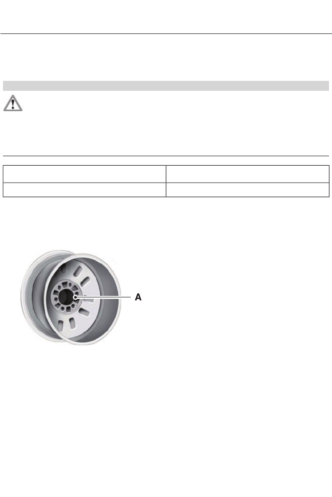
TECHNICAL SPECIFICATIONS
Wheel Lug Nut Torque Specifications
WARNING
When a wheel is installed, always remove any corrosion, dirt or foreign materials
present on the mounting surfaces of the wheel or the surface of the wheel hub,
brake drum or brake disc that contacts the wheel. Make sure that any fasteners
that attach the rotor to the hub are secured so they do not interfere with the mounting
surfaces of the wheel. Installing wheels without correct metal-to-metal contact at the
wheel mounting surfaces can cause the wheel nuts to loosen and the wheel to come off
while the vehicle is in motion, resulting in loss of control.
Ib-ft (Nm)*
Bolt size
100 (135)M12 x 1.5
*Torque specifications are for nut and bolt threads free of dirt and rust. Use only Ford
recommended replacement fasteners.
Retighten the lug nuts to the specified torque within 100 miles (160 kilometers) after any
wheel disturbance (such as tire rotation, changing a flat tire, wheel removal).
E145950
Wheel pilot boreA
Inspect the wheel pilot bore and
mounting surface prior to installation.
Remove any visible corrosion or loose
particles.
285
Wheels and Tires

ENGINE SPECIFICATIONS
2.0L ATK iVCT EngineEngine
122Cubic inches
Minimum 87 octaneRequired fuel
1-3-4-2Firing order
Coil on plug (COP)Ignition system
12.3:1Compression
ratio
0.051 in. ± 0.002 in. (1.3 mm ± 0.05 mm)Spark plug gap
286
Capacities and Specifications

MOTORCRAFT PARTS
2.0L ATK iVCT EngineComponent
FA-1911Air filter
element1
FL-910-S
Oil filter2
BXT-96R-500Battery
BXT-96R-590
SP-531
Spark plugs3
FP-71Cabin air filter
WW-2700 (driver side)Windshield
wiper blade WW-2601 (passenger side)
1 Failure to use the correct air filter element may result in severe engine damage. The
customer warranty may be void for any damage to the engine if the correct air filter
element is not used.
2 Only use the specified replacement oil filter. The use of a non-specified oil filter can
result in engine damage.
3 For spark plug replacement, see your authorized dealer. Replace the spark plugs at the
appropriate intervals. See Scheduled Maintenance (page 438).
Note: Replace the spark plugs with ones that meet Ford material and design specifications
for your vehicle, such as Motorcraft® or equivalent replacement parts. The customer
warranty may be void for any damage to the engine if such spark plugs are not used.
287
Capacities and Specifications
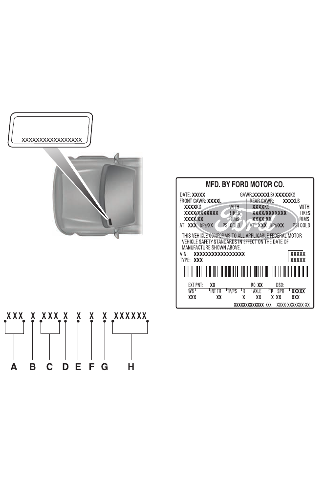
VEHICLE IDENTIFICATION
NUMBER
The vehicle identification number is
located on the left-hand side of the
instrument panel.
E142476
Please note that in the graphic, XXXX is
representative of your vehicle identification
number.
The Vehicle Identification Number contains
the following information:
E142477
World manufacturer identifierA
Brake system, Gross Vehicle
Weight Rating, Restraint Devices
and their locations
B
Make, vehicle line, series, body
type
C
Engine typeD
Check digitE
Model yearF
Assembly plantG
Production sequence numberH
VEHICLE CERTIFICATION
LABEL
E142478
The National Highway Traffic Safety
Administration Regulations require that a
Safety Compliance Certification Label be
affixed to a vehicle and prescribe where
the Safety Compliance Certification Label
may be located. The Safety Compliance
Certification Label shall be affixed to either
the door hinge pillar, the door latch post,
or the edge of the door near the door latch,
next to the driver's seating position.
288
Capacities and Specifications
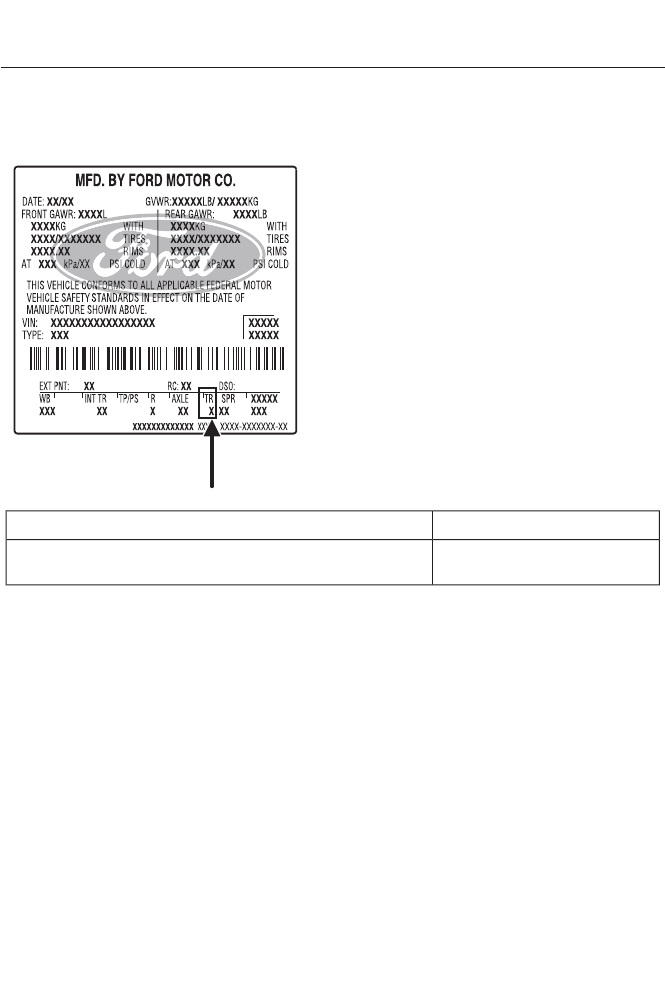
TRANSMISSION CODE
DESIGNATION
E142806
The transmission code is on the Safety
Compliance Certification Label. The
following table shows the transmission
code along with the transmission
description.
CodeDescription
JElectronic continuously variable transmission (ECVT),
automatic, power split, shift by wire
289
Capacities and Specifications

TECHNICAL SPECIFICATIONS
Ford Part Number /
Ford Specification
Ford Part Name or
Equivalent
CapacityItem
PM-1-C /Motorcraft DOT 4 LV
High Performance
Brake Fluid
Between MIN and
MAX on reservoir
Brake fluid 1
WSS-M6C65-A2 and
ISO 4925 Class 6
XG-4 or XL-5 or equi-
valent
Multi-Purpose
Grease (lithium
grease)
Not applicableDoor latch, hood
latch, auxiliary hood
latch, trunk latch, seat
tracks.
/ESB-M1C93-B
XL-1 /NoneMotorcraft Penet-
rating and Lock
Lubricant
Not applicableLock cylinder
XT-10-QLV MERCON
LV
Motorcraft MERCON
LV ATF
5.7 qt (5.4L)Automatic transmis-
sion fluid 2, 3
WSS-M2C945-AMotorcraft SAE 5W-
20 or equivalent
4.5 qt (4.3L)
Engine oil 4, 5
VC-3DIL-B (U.S.)Motorcraft Orange
Antifreeze / Coolant
Prediluted
8.8 qt (8.3L)Energi engine coolant
6CVC-3DIL-B
(Canada)
7 qt (7.4L)Hybrid engine coolant
6
/WSS-M97B44-D2
1 qt (1.1L)Inverter system
controller coolant6
ZC-32-A (U.S.)Motorcraft Premium
Windshield Washer
Concentrate (U.S.)
Fill as requiredWindshield washer
fluid CXC-37-(A, B, D, and
F) (Canada)
Premium Quality
Windshield Washer
Fluid (Canada)
/WSB-M8B16-A2
Not applicableNot applicable14 gal (53L)Energi fuel tank
13.5 gal (51.1L)Hybrid fuel tank
YN-19 (US)Motorcraft R-134a
Refrigerant
1.25 lb (0.567 kg)
A/C Refrigerant7
CYR-16-R (Canada)
290
Capacities and Specifications

Ford Part Number /
Ford Specification
Ford Part Name or
Equivalent
CapacityItem
/WSH-M17B19-A
YN-32Motorcraft POE
Refrigerant
Compressor Oil
5.17 fl oz (152.8 ml)A/C Refrigerant
Compressor Oil7/WSS-M2C31-B2
1Use only Motorcraft DOT 4 LV High Performance Brake Fluid, or equivalent, meeting
WSS-M6C65-A2 and ISO 4925 Class 6. Use of any fluid other than the recommended
fluid may cause brake system damage.
2Approximate dry fill capacity. Actual amount may vary during fluid changes.
3Automatic transmissions that require Motorcraft MERCON LV transmission fluid should
only use Motorcraft MERCON LV transmission fluid.
Use of any fluid other than the recommended fluid may cause transmission damage.
Change the automatic transmission fluid at the correct service interval. See Scheduled
Maintenance (page 438).
4Your engine has been designed to use engine oil that meets Ford specification. It is also
acceptable to use an engine oil of recommended viscosity grade that displays the API
Certification Mark for gasoline engines.
5Do not use supplemental engine oil additives, cleaners or other engine treatments. They
are unnecessary and could lead to engine damage that is not covered by Ford warranty.
Using oils other than the one specified can result in longer engine cranking periods, reduced
engine performance, reduced fuel economy and increased emission levels.
6Add the coolant type originally equipped in your vehicle.
7
WARNING
The A/C refrigerant system contains refrigerant R-134a under high pressure. Opening
the A/C refrigerant system can cause personal injury. A/C refrigerant system is to
be serviced only by qualified personnel.
291
Capacities and Specifications

For a complete listing of the accessories
that are available for your vehicle, please
contact your dealer or visit our online store
at: Accessories.Ford.com (U.S. only).
Ford Custom Accessories are available for
your vehicle through your local Ford or Ford
of Canada dealer. Ford Motor Company
will repair or replace any properly
dealer-installed Ford Custom Accessories
found to be defective in factory-supplied
materials or workmanship during the
warranty period, as well as any component
damaged by the defective accessories. The
accessories will be warranted for
whichever provides you the greatest
benefit:
• 12 months or 12,000 miles (20,000
km) (whichever occurs first), or
• the remainder of your new vehicle
limited warranty.
Contact your dealer for details and a copy
of the warranty.
Exterior style
• Hood deflectors
• Side-window deflectors
• Splash guards
• Rear spoiler
• Wheels
• Bumper protectors
Interior style
• All-weather floor mats
• Rear seat entertainment*
• Premium carpeted floor mats
• Lighted door sill plates
• Electrochromatic
compass/temperature interior mirrors
Lifestyle
• Ash cup / smoker's packages
• Roof racks and carriers*
• Cargo area protectors
• Cargo net
• Cargo organizers
• Interior light kit
Peace of mind
• Remote start
• Vehicle security systems
• Wheel locks
• Bumper-mounted parking sensor*
• Locking fuel plug for capless fuel
system
*Ford Licensed Accessories (FLA) are
warranted by the accessory
manufacturer's warranty. Ford Licensed
Accessories are fully designed and
developed by the accessory manufacturer
and have not been designed or tested to
Ford Motor Company engineering
requirements. Contact your Ford dealer for
details regarding the manufacturer's
limited warranty and a copy of the FLA
product limited warranty offered by the
accessory manufacturer.
For maximum vehicle performance, keep
the following information in mind when
adding accessories or equipment to your
vehicle:
292
Accessories

• When adding accessories, equipment,
passengers and luggage to your
vehicle, do not exceed the total weight
capacity of the vehicle or of the front
or rear axle (GVWR or GAWR as
indicated on the Safety Compliance
Certification label). Consult your
authorized dealer for specific weight
information.
• The Federal Communications
Commission (FCC) and Canadian
Radio Telecommunications
Commission (CRTC) regulate the use
of mobile communications systems —
such as two-way radios, telephones
and theft alarms - that are equipped
with radio transmitters. Any such
equipment installed in your vehicle
should comply with FCC or CRTC
regulations and should be installed
only by a qualified service technician.
• Mobile communications systems may
harm the operation of your vehicle,
particularly if they are not properly
designed for automotive use.
• To avoid interference with other vehicle
functions, such as anti-lock braking
systems, amateur radio users who
install radios and antennas onto their
vehicle should not locate the amateur
radio antennas in the area of the
driver's side hood.
• Any non-Ford custom electrical or
electronic accessories or components
that are added to the vehicle by the
authorized dealer or the owner, may
adversely affect battery performance
and durability, and may also adversely
affect the performance of other
electrical systems in the vehicle.
293
Accessories

PROTECT YOURSELF FROM THE RISING
COST OF VEHICLE REPAIRS WITH A FORD
EXTENDED SERVICE PLAN.
SERVICE PLANS (U.S. Only)
More than 32 million Ford and Lincoln
owners have discovered the powerful
protection of Ford Extended Service Plan.
It is the only extended service plan backed
by Ford Motor Company, and provides
peace of mind protection beyond the New
Vehicle Limited Warranty coverage.
Ford ESP Can Quickly Pay for Itself
One service bill – the cost of parts and
labor – can easily exceed the price of your
Ford Extended Service Plan. With Ford
ESP, you minimize your risk for unexpected
repair bills and rising repair costs.
Up to 500+ Covered Vehicle
Components
There are four Extended Service Plans with
different levels of coverage. Ask your
dealer for details.
1. PremiumCARE - Our most
comprehensive coverage. With over
500 covered components, this plan is
so complete that we generally only
discuss what’s not covered.
2. ExtraCARE - Covers 113 components,
and includes many high-tech items.
3. BaseCARE - Covers 84 components.
4. PowertrainCARE - Covers 29 critical
components.
Ford Extended Service Plan is honored by
all Ford and Lincoln Dealers in the U.S. and
Canada. It is the only extended service plan
authorized and backed by Ford Motor
Company.
That means you get:
• Reliable, quality service anywhere you
go
• Repairs performed by factory trained
technicians, using Genuine Ford and
Lincoln parts
Rental Car Reimbursement
1st day Rental Benefit
You take advantage of replacement
transportation if your vehicle is at the
dealership for same day covered repairs.
Extended Rental Benefits
If your vehicle is kept overnight for covered
repairs, you are eligible for rental car
coverage, including Bumper to Bumper
warranty repairs, or Field Service Actions.
Roadside Assistance
Exclusive 24/7 roadside assistance,
including:
• Towing, flat-tire change and battery
jump starts
• Out of fuel and lock-out assistance
• Travel expense reimbursement for
lodging, meals and rental car
• Destination assistance for taxi, shuttle,
rental car coverage and emergency
transportation
Transferable Coverage
If you sell your vehicle before your Ford
Extended Service Plan coverage expires,
you can transfer any remaining coverage
to the new owner. Whenever you sell your
vehicle, prospective buyers may have a
higher degree of confidence that vehicle
was properly maintained with Ford ESP,
thereby improving resale value.
294
Ford Extended Service Plan (ESP)

Avoid the Rising Cost of Properly
Maintaining Your Vehicle!
Ford Extended Service Plan also offers a
Premium Maintenance Plan that covers all
scheduled maintenance, and select items
that routinely wear out.
The coverage is prepaid, so you never have
to worry about affording your vehicle
maintenance. It covers regular checkups,
routine inspections, preventive care and
replacement of select items that require
periodic attention for normal wear:
• Windshield Wiper Blades
• Spark Plugs (except in California)
• The Clutch Disc
• Brake Pads and Linings
• Shock Absorbers
• Belts and Hoses
• Diesel Exhaust Fluid Replenishment
Contact your selling Ford or Lincoln
dealership today so they can customize a
Ford Extended Service Plan that fits your
driving lifestyle and budget.
Interest Free Finance Options
Available
Take advantage of our interest free
installment payment plan. Just a 10%
down payment will provide you with an
affordable, no interest, no fee payment
program.
To learn more, call our Ford ESP specialists
at 800-367-3377. Don’t forget to ask about
our interest free payment program,
allowing you all the security and benefits
Ford ESP has to offer while paying over
time. You are pre-approved with no credit
checks, no hassles!
Complete the information below and mail
to:
Ford ESP
P.O. Box 8072
Royal Oak, MI 48068-0039
Name (PLEASE PRINT)
APT.#ADDRESS
ZIPSTATECITY
E-MAIL
295
Ford Extended Service Plan (ESP)

SERVICE PLANS (CANADA ONLY)
You can get more protection for your
vehicle by purchasing a Ford Extended
Service Plan. Ford Extended Service Plan
is the only service contract backed by Ford
Motor Company of Canada, Limited.
Depending on the plan you purchase, Ford
Extended Service Plan provides benefits
such as:
• Rental reimbursement
• Coverage for certain maintenance and
wear items
• Protection against repair costs after
your New Vehicle Limited Warranty
Coverage expires
• Roadside Assistance benefits
There are several Ford Extended Service
Plans available in various time, distance
and deductible combinations. Each plan
is tailored to fit your own driving needs,
including reimbursement for towing and
rental.
When you purchase Ford Extended Service
Plan, you receive added peace-of-mind
protection throughout Canada and the
United States, provided by a network of
participating Ford Motor Company dealers.
The Lincoln Maintenance Protection Plan
is honored at authorized Lincoln dealers.
Note: Repairs performed outside of Canada
and the United States are not eligible for
Ford Extended Service Plan coverage.
This information is subject to change.
For more information, visit your local Ford
of Canada dealer or www.ford.ca to find
the Ford Extended Service Plan that is right
for you.
296
Ford Extended Service Plan (ESP)

GENERAL INFORMATION
Radio Frequencies and Reception
Factors
AM and FM frequencies are established by
the Federal Communications Commission
(FCC) and the Canadian Radio and
Telecommunications Commission (CRTC).
Those frequencies are:
• AM: 530, 540-1700, 1710 kHz
• FM: 87.9-107.7, 107.9 MHz
Radio Reception Factors
The further you travel from an FM station, the weaker the
signal and the weaker the reception.
Distance and strength
Hills, mountains, tall buildings, bridges, tunnels, freeway
overpasses, parking garages, dense tree foliage and
thunderstorms can interfere with the reception.
Terrain
When you pass a ground-based broadcast repeating
tower, a stronger signal may overtake a weaker one and
result in the audio system muting.
Station overload
CD and CD Player Information
Note: CD units play commercially pressed
4.75-inch (12 centimeter) audio compact
discs only. Due to technical incompatibility,
certain recordable and re-recordable
compact discs may not function correctly
when used in Ford CD players.
Note: Do not insert CDs with homemade
paper (adhesive) labels into the CD player
as the label may peel and cause the CD to
become jammed. You should use a
permanent felt tip marker rather than
adhesive labels on your homemade CDs.
Ballpoint pens may damage CDs. Please
contact an authorized dealer for further
information.
Note: Do not use any irregularly shaped
discs or discs with a scratch protection film
attached.
Always handle discs by their edges only.
Clean the disc with an approved CD
cleaner only. Wipe it from the center of the
disc toward the edge. Do not clean in a
circular motion.
Do not expose discs to direct sunlight or
heat sources for extended periods.
MP3 Track and Folder Structure
Audio systems capable of recognizing and
playing MP3 individual tracks and folder
structures work as follows:
• There are two different modes for MP3
disc playback: MP3 track mode
(system default) and MP3 folder
mode.
• MP3 track mode ignores any folder
structure on the MP3 disc. The player
numbers each MP3 track on the disc
(noted by the .mp3 file extension) from
T001 to a maximum of T255. The
maximum number of playable MP3
files may be less depending on the
structure of the CD and exact model
of radio present.
297
Audio System
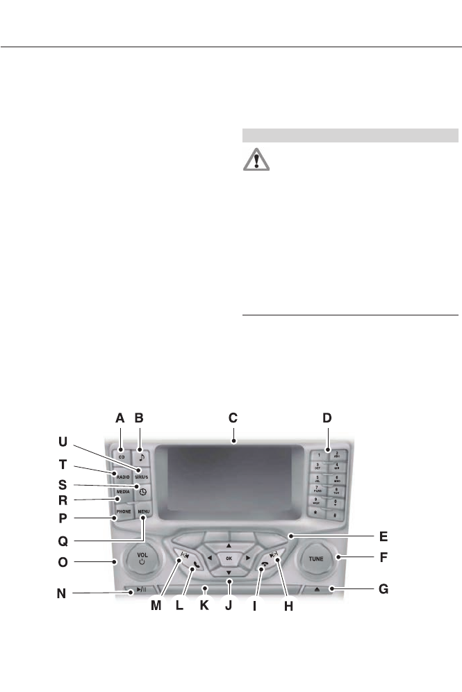
• MP3 folder mode represents a folder
structure consisting of one level of
folders. The CD player numbers all MP3
tracks on the disc (noted by the .mp3
file extension) and all folders
containing MP3 files, from F001
(folder) T001 (track) to F253 T255.
• Creating discs with only one level of
folders helps with navigation through
the disc files.
If you are burning your own MP3 discs, it is
important to understand how the system
reads the structures you create. While
various files may be present, (files with
extensions other than mp3), only files with
the .mp3 extension are played; other files
are ignored by the system. This enables
you to use the same MP3 disc for a variety
of tasks on your work computer, home
computer and your in-vehicle system.
In track mode, the system displays and
plays the structure as if it were only one
level deep (all .mp3 files play, regardless
of being in a specific folder). In folder
mode, the system only plays the .mp3 files
in the current folder.
AUDIO UNIT - VEHICLES WITH:
AM/FM/CD/SYNC/SATELLITE
RADIO
WARNING
Driving while distracted can result in
loss of vehicle control, accident and
injury. Ford strongly recommends
that you use extreme caution when using
any device or feature that may take your
focus off the road. Your primary
responsibility is the safe operation of the
vehicle. We recommend against the use
of any handheld device while driving,
encourage the use of voice-operated
systems when possible and that you
become aware of applicable state and
local laws that may affect use of electronic
devices while driving.
Note: Depending on your vehicle option
package, your system may look different
from what you see here.
Note: Some features, such as SIRIUS
satellite radio, may not be available in your
location. Check with an authorized dealer.
E144488
298
Audio System

CD: Press this button to listen to a CD. Press the function buttons below the
radio screen to select on-screen options of Repeat or Shuffle.
A
SOUND: Press this button to access settings for Treble, Middle, Bass, Fade
and Balance. Use the up and down arrow buttons to select the various settings.
When you make your selection, press the left and right arrow buttons to change
the settings. Press OK to set or press MENU to exit. Sound settings can be set
for each audio source independently.
B
Display screen: Shows audio and SYNC information.C
Number block: In radio mode, store your favorite stations for later access.
When tuned to any station, press and hold a preset button until sound returns.
In CD mode, press a button to select a track. In phone mode, press the buttons
to enter a phone number.
D
Function buttons: Select different functions of the audio system depending
on which mode you are in (such as Radio mode or CD mode).
E
TUNE: Turn to search the frequency band in individual increments.F
Eject: Press this button to eject a CD.G
Seek: In radio mode, select a frequency band and press this button. The system
stops at the first station up the band. Press and hold the button to move quickly
to the next strong radio station or memory preset. In CD mode, press this button
to select the next track. Press and hold the button to move quickly forward
through the current track.
H
End phone call: Press this button to end a phone call.I
Cursor arrows and OK: Use the up and down arrow buttons to select the
various settings. When you make your selection, press the left and right arrow
buttons to change the settings. Press OK to set or press MENU to exit.
J
CD slot: Insert a CD.K
Pick-up or Make phone call: Press this button to either pick-up an incoming
phone call or to make a phone call.
L
Seek: In radio mode, select a frequency band and press this button. The system
stops at the first station down the band. Press and hold the button to move
quickly to the previous strong radio station or memory preset. In CD mode, press
this button to select the previous track. Press and hold the button to move
quickly backward through the current track.
M
Play/Pause: Press to either play or pause a track when listening to a CD.N
VOL and Power: Press this button to turn the system off and on. Turn it to
adjust the volume.
O
PHONE: Press this button to access the phone features of the SYNC® system.
See SYNC™ (page 310).
P
MENU: Press this button to access different audio system features. See Menu
Structure later in this section.
Q
299
Audio System
MEDIA: Press this button to access your auxiliary input jack or switch between
devices you plug into the input jack or USB port.
R
Clock: Press this button to access the clock setting. Use the center arrow
controls to change the hours and minutes. You can also set the clock by pressing
the MENU button and scrolling to Clock Settings.
S
RADIO: Press this button to listen to the radio or change radio frequencies
bands. Press the function buttons below the radio screen to select different
radio functions.
T
SIRIUS: Press this button to listen to SIRIUS satellite radio.U
AUDIO UNIT - VEHICLES WITH:
PREMIUM AM/FM/CD
WARNING
Driving while distracted can result in
loss of vehicle control, accident and
injury. Ford strongly recommends
that you use extreme caution when using
any device or feature that may take your
focus off the road. Your primary
responsibility is the safe operation of the
vehicle. We recommend against the use
of any handheld device while driving,
encourage the use of voice-operated
systems when possible and that you
become aware of applicable state and
local laws that may affect use of electronic
devices while driving.
Note: The MyFord Touch® system controls
most of the audio features. See MyFord
Touch™ (page 348).
300
Audio System
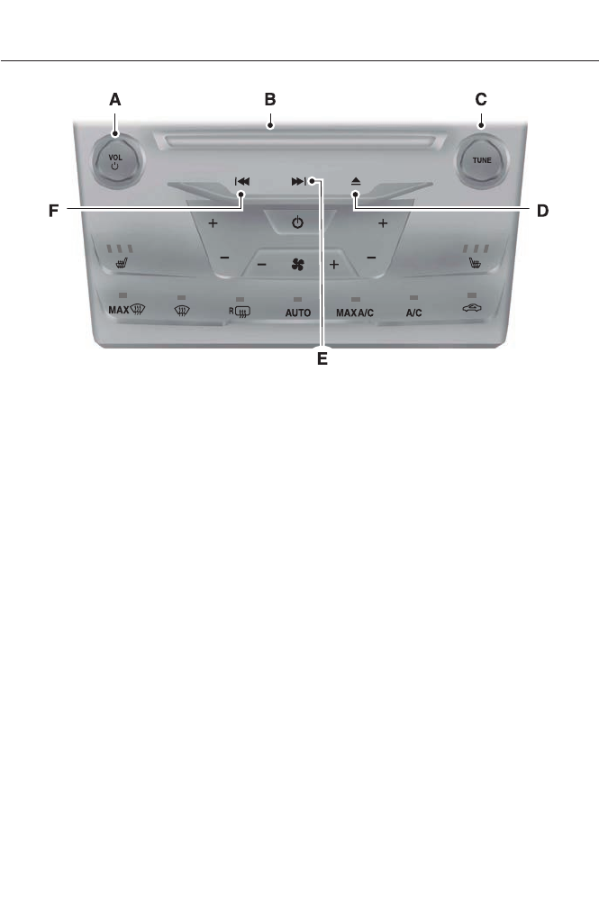
E144489
VOL and Power: Press this button to turn the system off and on. Turn it to
adjust the volume.
A
CD slot: Insert a CD.B
TUNE: Once you select a frequency band, turn the control to find the desired
station manually.
C
Eject: Press this button to eject a CD.D
Seek and Fast Forward: In radio mode, select a frequency band and press
this button. The system stops at the first station up the band. Press and hold
the button to move quickly to the next strong radio station or memory preset.
In CD mode, press this button to select the next track. Press and hold the button
to move quickly forward through the current track.
E
Seek and Reverse: In radio mode, select a frequency band and press this
button. The system stops at the first station down the band. Press and hold
the button to move quickly to the previous strong radio station or memory
preset. In CD mode, press this button to select the previous track. Press and
hold the button to move quickly backward through the current track.
F
301
Audio System
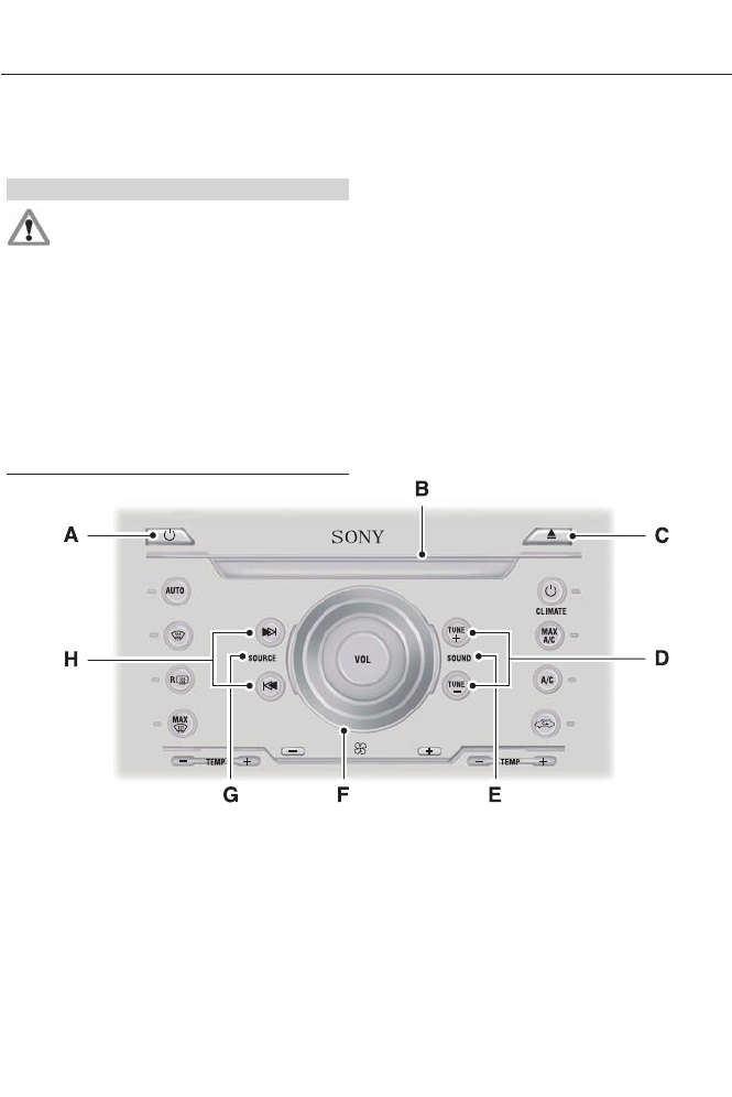
AUDIO UNIT - VEHICLES WITH:
SONY AM/FM/CD
WARNING
Driving while distracted can result in
loss of vehicle control, accident and
injury. Ford strongly recommends
that you use extreme caution when using
any device or feature that may take your
focus off the road. Your primary
responsibility is the safe operation of the
vehicle. We recommend against the use
of any handheld device while driving,
encourage the use of voice-operated
systems when possible and that you
become aware of applicable state and
local laws that may affect use of electronic
devices while driving.
Note: The MyFord Touch® system controls
most of the audio features. See MyFord
Touch™ (page 348).
E144490
Power: Press this button to turn the system off and on.A
CD slot: Insert a CD.B
Eject: Press this button to eject a CD.C
TUNE + and TUNE -: Press these buttons to search the frequency bands in
individual increments.
D
SOUND: Press this button to access settings for Treble, Middle, Bass, Fade
and Balance.
E
302
Audio System

VOL: Turn the control to adjust the volume.F
SOURCE: Press this button to access different audio modes such as AM, FM
and A/V Input.
G
Seek, Reverse and Fast Forward: In radio mode, select a frequency band
and press one of these buttons. The system stops at the first station it finds in
that direction. Press and hold one of these buttons to move quickly in that
direction to the next strong radio station or memory preset. In CD mode, press
one of these buttons to select the previous or next track. Press and hold one of
these buttons to move quickly in that direction within the current track.
H
Menu Structure
Note: Depending on your system, some
options may appear slightly different.
Press MENU.
Press the up and down arrow buttons to
scroll through the options.
Press the right arrow to enter a menu.
Press the left arrow to exit a menu.
Press OK to confirm a selection.
Radio
Use the left and right arrows to go up or down the
frequency band.
Manual tune
Select for a brief sampling of all available channels.Scan
Select to store the six strongest local stations on the AM-
AST and FM-AST frequency bands.
AST
Select to have the system search by certain music
categories (such as Rock, Pop or Country).
PTY/Set Category
Select to view additional broadcast data, if available. This
feature defaults to off. RBDS must be on for you to set a
category.
RBDS/RDS
303
Audio System

SIRIUS
Select for a brief sampling of all available channels.Scan
Select to view your satellite radio electronic serial number
(ESN). You will need this number when communicating
with SIRIUS® to activate, modify or track your account.
Show ESN
Select to view available satellite radio channels. Press OK
to open a list of the following options for this channel:
Tune Channel, Skip Channel or Lock Channel. Once you
skip or lock a channel, you can only access it by pressing
Direct and entering the channel number. Locking or
unlocking a channel requires your PIN.
Channel Guide
Select to view channel categories (such as Pop, Rock or
News). If you select a category, seek and scan functions
only stop on channels in that category.
Set Category
Select to turn off or turn on alerts for songs, artists or
teams. The system alerts you when the selection is playing
on another channel. Save up to 20 alerts.
Alerts
Use your PIN to unlock previously locked stations.Unlock All Stations
Use to restore any channels you previously skipped.Skip No stations
Select to create a PIN, which allows you to lock or unlock
channels. Your initial PIN is 1234.
Parental Lock (PIN)
Audio Settings
Automatically adjusts the volume to compensate for
speed and wind noise. You can set the system between
0 and +7.
Spd. Comp. Vol.
Select to adjust settings for Treble, Middle, Bass, Fade
and Balance.
Sound
Select to optimize sound quality for the chosen seating
position.
Occupancy Mode
Select to view additional broadcast data, if available. This
feature defaults to off. RBDS must be on for you to set a
category.
RBDS/RDS Text
Choose between STEREO SURROUND mode and STEREO
mode.
DSP
304
Audio System

CD Settings
Select to scan all disc selections.Scan All
Select to scan all music in the current MP3 folder.Scan Folder
Select to bring soft and loud passages together for a more
consistent listening level.
CD Compression
Clock Settings
Select to set the time.Set Time
Select to set the calendar date.Set Date
Select to view clock time in a 12-hour mode or 24-hour
mode.
24h Mode
Display Settings
Select to change display brightness.Dimming
Select to display the language in English, French or
Spanish.
Language
Select to display the outside temperature in Fahrenheit
or Celsius.
Temp. setting
SATELLITE RADIO (IF EQUIPPED)
SIRIUS® broadcasts a variety of music,
news, sports, weather, traffic and
entertainment satellite radio channels. For
more information and a complete list of
SIRIUS satellite radio channels, visit
www.siriusxm.com in the United States,
www.sirius.ca in Canada, or call SIRIUS at
1-888-539-7474.
Note: This receiver includes the eCos
real-time operating system. eCos is
published under the eCos License.
305
Audio System
Satellite Radio Reception Factors
Potential satellite radio reception issues
For optimal reception performance, keep the antenna
clear of snow and ice build-up and keep luggage and other
material as far away from the antenna as possible.
Antenna obstructions
Hills, mountains, tall buildings, bridges, tunnels, freeway
overpasses, parking garages, dense tree foliage and
thunderstorms can interfere with your reception.
Terrain
When you pass a ground-based broadcast-repeating
tower, a stronger signal may overtake a weaker one and
the audio system may mute.
Station overload
Your display may show ACQUIRING . . . to indicate the
interference and the audio system may mute.
Satellite radio signal interfer-
ence
SIRIUS® Satellite Radio Service
Note: SIRIUS reserves the unrestricted right
to change, rearrange, add or delete
programming including canceling, moving
or adding particular channels, and its prices,
at any time, with or without notice to you.
Ford Motor Company shall not be
responsible for any such programming
changes.
E142593
SIRIUS satellite radio is a
subscription-based satellite radio service
that broadcasts a variety of music, sports,
news, weather, traffic and entertainment
programming. Your factory-installed
SIRIUS satellite radio system includes
hardware and a limited subscription term,
which begins on the date of sale or lease
of your vehicle. See an authorized dealer
for availability.
For more information on extended
subscription terms (a service fee is
required), the online media player and a
complete list of SIRIUS satellite radio
channels, and other features, please visit
www.siriusxm.com in the United States,
www.sirius.ca in Canada, or call SIRIUS at
1-888-539-7474.
Satellite Radio Electronic Serial
Number (ESN)
You need your ESN to activate, modify or
track your satellite radio account. When in
satellite radio mode, press Options.
306
Audio System

Troubleshooting
Possible actionConditionRadio display
No action required. This
message should disappear
shortly.
Radio requires more than
two seconds to produce
audio for the selected
channel.
Acquiring
If this message does not
clear shortly, or with an igni-
tion key cycle, your receiver
may have a fault. See an
authorized dealer for service.
There is an internal module
or system failure present.
Sat Fault/SIRIUS system
failure
Tune to another channel or
choose another preset.
The channel is no longer
available.
Invalid Channel
Contact SIRIUS at 1-888-
539-7474 to subscribe to
the channel, or tune to
another channel.
Your subscription does not
include this channel.
Unsubscribed Channel
The signal is blocked. When
you move into an open area,
the signal should return.
The signal is lost from the
SIRIUS satellite or SIRIUS
tower to your vehicle
antenna.
No Signal
No action required. The
process may take up to
three minutes.
Update of channel
programming in progress.
Updating
Contact SIRIUS at 1-888-
539-7474 to resolve
subscription issues.
Your satellite service is no
longer available.
Call SIRIUS 1-888-539-7474
Use the channel guide to
turn off the Lock or Skip
function on that station.
All the channels in the
selected category are either
skipped or locked.
None found. Check Channel
Guide.
No action required.SIRIUS has updated the
channels available for your
vehicle.
Subscription Updated
307
Audio System
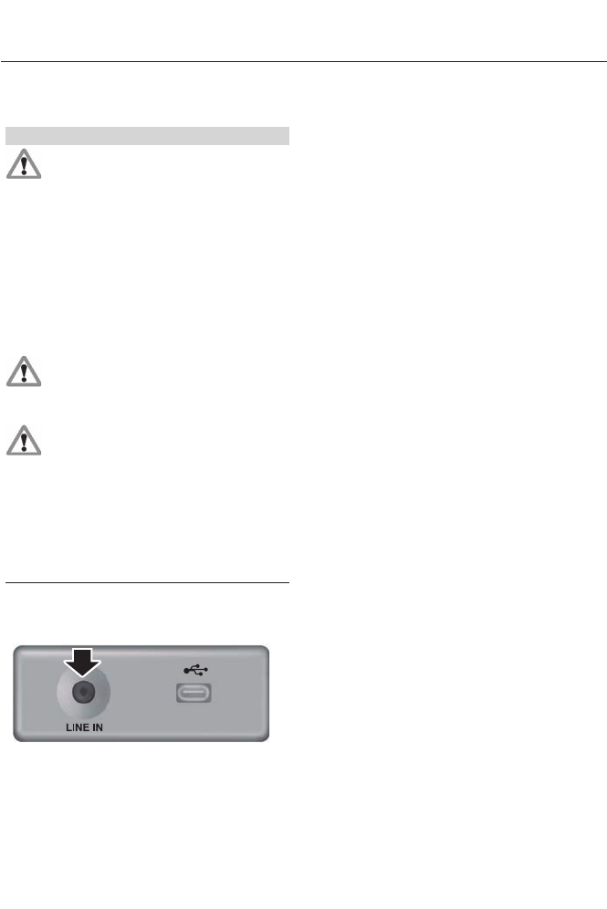
AUXILIARY INPUT JACK
WARNINGS
Driving while distracted can result in
loss of vehicle control, crash and
injury. We strongly recommend that
you use extreme caution when using any
device that may take your focus off the
road. Your primary responsibility is the safe
operation of your vehicle. We recommend
against the use of any hand-held device
while driving and encourage the use of
voice-operated systems when possible.
Make sure you are aware of all applicable
local laws that may affect the use of
electronic devices while driving.
For safety reasons, do not connect
or adjust the settings on your
portable music player while your
vehicle is moving.
Store the portable music player in a
secure location, such as the center
console or the glove box, when your
vehicle is moving. Hard objects may
become projectiles in a collision or sudden
stop, which may increase the risk of serious
injury. The audio extension cable must be
long enough to allow the portable music
player to be safely stored while your
vehicle is moving.
E149149
The auxiliary input jack allows you to
connect and play music from your portable
music player through your vehicle speakers.
You can use any portable music player
designed for use with headphones. Your
audio extension cable must have male
1/8th-inch (3.5 millimeter) connectors at
each end.
1. Switch off the engine, radio and
portable music player. Set the parking
brake and put the transmission in
position P (vehicle with an automatic
transmission) or neutral (vehicle with
a manual transmission).
2. Plug the extension cable from the
portable music player into the auxiliary
input jack.
3. Switch the radio on. Select either a
tuned FM station or a CD.
4. Adjust the volume as desired.
5. Switch your portable music player on
and adjust its volume to half its
maximum level.
6. Press AUX until LINE or LINE IN
appears in the display. You should hear
music from your device even if it is low.
7. Adjust the volume on your portable
music player until it reaches the volume
level of the FM station or CD. Do this
by switching back and forth between
the AUX and FM or CD controls.
308
Audio System
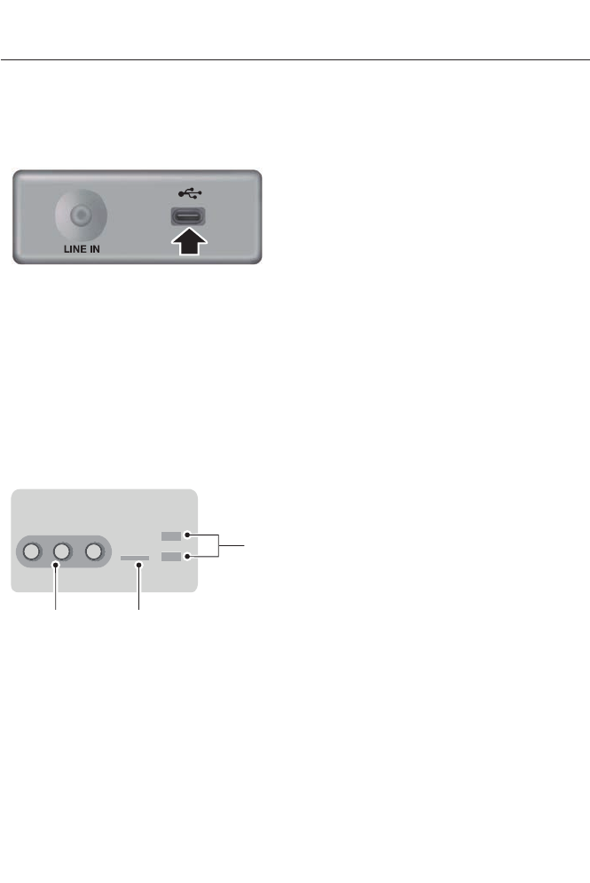
USB PORT (IF EQUIPPED)
E149148
The USB port allows you to plug in media
playing devices, memory sticks and charge
devices (if supported). See SYNC® (page
?).
MEDIA HUB (IF EQUIPPED)
The media hub is located in the center
console and has the following features:
C
B
A
E142605
A/V inputsA
SD card slotB
USB portsC
See MyFord Touch™ (page 348).
309
Audio System
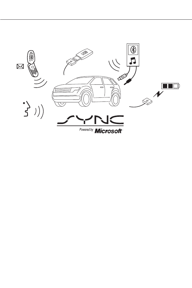
GENERAL INFORMATION
E142598
SYNC is an in-vehicle communications
system that works with your
Bluetooth-enabled cellular phone and
portable media player. This allows you to:
• Make and receive calls.
• Access and play music from your
portable music player.
• Use 911 Assist, Vehicle Health Report
and SYNC Services (Traffic, Directions
& Information).*
• Use applications, such as Pandora and
Stitcher, via SYNC AppLink.
• Access phonebook contacts and music
using voice commands.
• Stream music from your connected
phone.
• Text message.
• Use the advanced voice recognition
system
• Charge your USB device (if your device
supports this).
*These features require activation.
Make sure that you review your device's
manual before using it with SYNC.
Support
The SYNC support team is available to
help you with any questions you cannot
answer on your own.
Monday-Saturday, 8:30am-8:00pm EST.
In the United States, call 1-888-270-1055.
In Canada, call 1-800-565-3673.
310
SYNC™
Times are subject to change due to
holidays.
SYNC Owner Account
Why do I need a SYNC owner account?
• Required to activate Vehicle Health
Report and to view the reports online.
• Required to activate the
subscription-based SYNC Services and
to personalize your Saved Points and
Favorites.
• Essential for keeping up with the latest
software downloads available for
SYNC.
• Access to customer support for any
questions you may have.
Driving Restrictions
For your safety, certain features are
speed-dependent and restricted when your
vehicle is traveling over 3 mph (5 km/h).
Safety Information
WARNING
Driving while distracted can result in
loss of vehicle control, crash and
injury. We strongly recommend that
you use extreme caution when using any
device that may take your focus off the
road. Your primary responsibility is the safe
operation of your vehicle. We recommend
against the use of any hand-held device
while driving and encourage the use of
voice-operated systems when possible.
Make sure you are aware of all applicable
local laws that may affect the use of
electronic devices while driving.
When using SYNC:
• Do not operate playing devices if the
power cords or cables are broken, split
or damaged. Place cords and cables
out of the way, so they do not interfere
with the operation of pedals, seats,
compartments or safe driving abilities.
• Do not leave playing devices in your
vehicle during extreme conditions as it
could cause them damage. See your
device's manual for further information.
• Do not attempt to service or repair the
system. See an authorized dealer.
Privacy Information
When a cellular phone is connected to
SYNC, the system creates a profile within
your vehicle that is linked to that cellular
phone. This profile is created in order to
offer you more cellular features and to
operate more efficiently. Among other
things, this profile may contain data about
your cellular phone book, text messages
(read and unread), and call history,
including history of calls when your cellular
phone was not connected to the system.
In addition, if you connect a media device,
the system creates and retains an index of
supported media content. The system also
records a short development log of
approximately 10 minutes of all recent
system activity. The log profile and other
system data may be used to improve the
system and help diagnose any problems
that may occur.
The cellular profile, media device index,
and development log will remain in the
vehicle unless you delete them and are
generally accessible only in the vehicle
when the cellular phone or media player
is connected. If you no longer plan to use
the system or the vehicle, we recommend
you perform a Master Reset to erase all
stored information.
311
SYNC™

System data cannot be accessed without
special equipment and access to the
vehicle's SYNC module. Ford Motor
Company and Ford of Canada will not
access the system data for any purpose
other than as described absent consent, a
court order, or where required by law
enforcement, other government
authorities, or other third parties acting
with lawful authority. Other parties may
seek to access the information
independently of Ford Motor Company and
Ford of Canada. For further privacy
information, see the sections on 911 Assist,
Vehicle Health Report, and Traffic,
Directions and Information.
USING VOICE RECOGNITION
This system helps you control many
features using voice commands. This
allows you to keep your hands on the
wheel and focus on what is in front of you.
Initiating a Voice Session
E142599
Push the voice icon. A tone
sounds and Listening appears in
the display. Say any of the
following:
If You Want ToSay
Stream audio from your phone."Bluetooth audio"
Cancel the requested action."Cancel"
Access the device connected to the auxiliary input jack."Line in"
Access mobile applications.
"Mobile apps" *
Make calls."Phone"
Access the SYNC Services portal.
"Services" *
Return to the main menu."SYNC"
Access the device connected to your USB port."USB"
Run a vehicle health report.
"Vehicle health report" *
Adjust the level of voice interaction and feedback."Voice settings"
Hear a list of voice commands available in the current
mode.
"Help"
* This is an optional feature and available in the United States only.
312
SYNC™
System Interaction and Feedback
The system provides feedback through
audible tones, prompts, questions and
spoken confirmations depending on the
situation and the chosen level of
interaction (voice settings). You can
customize the voice recognition system to
provide more or less instruction and
feedback.
The default setting is to a higher level of
interaction in order to help you learn to use
the system. You can change these settings
at any time.
Adjusting the Interaction Level
E142599
Push the voice icon. Say "Voice
settings" when prompted, then
any of the following:
The system:When you say:
Provides more detailed interaction and
guidance.
"Interaction mode standard"
Provides less audible interaction and more
tone prompts.
"Interaction mode advanced"
The system defaults to the standard interaction mode.
Confirmation prompts are short questions
the system asks when it is not sure of your
request or when there are multiple possible
responses to your request. For example,
the system may ask "Phone, is that
correct?". If turned off, the system simply
makes a best guess as to what you
requested and may ask you to confirm
settings.
The system:When you say:
Makes a best guess from the command;
you may still occasionally be asked to
confirm settings.
"Confirmation prompts off"
Clarifies your voice command with a short
question.
"Confirmation prompts on"
The system creates candidate lists when
it has the same confidence level of several
options based on your voice command.
When turned on, it may prompt you with
as many as four possibilities for
clarification.
For example, say "Say 1 after the tone to
call John Doe at home. Say 2 after the tone
to call Johnny Doe on mobile. Say 3 after
the tone to call Jane Doe at home." You
could also say "Say 1 after the tone to play
John Doe, Say 2 after the tone to play
Johnny Doe."
313
SYNC™

The system:When you say:
Makes a best guess from the media
candidate list. You may still occasionally
be asked questions.
"Media candidate lists off"
Clarifies your voice command for media
candidates.
"Media candidate lists on"
Makes a best guess from the phone
candidate list. You may still occasionally
be asked questions.
"Phone candidate lists off"
Clarifies your voice command for phone
candidates
"Phone candidate lists on"
Helpful Hints
• Make sure the interior of your vehicle is
as quiet as possible. Wind noise from
open windows and road vibrations may
prevent the system from correctly
recognizing spoken commands.
• After pressing the voice icon, wait until
after the tone sounds and Listening
appears before saying a command. Any
command spoken before this does not
register with the system.
• Speak naturally, without long pauses
between words.
• At any time, you can interrupt the
system while it is speaking by pressing
the voice icon.
USING SYNC™ WITH YOUR
PHONE
Hands-free calling is one of the main
features of SYNC. While the system
supports a variety of features, many are
dependent on your cellular phone's
functionality. At a minimum, most cellular
phones with Bluetooth wireless technology
support the following functions:
• Answering an incoming call.
• Ending a call.
• Using privacy mode.
• Dialing a number.
• Redialing.
• Call waiting notification.
• Caller ID.
Other features, such as text messaging
using Bluetooth and automatic phonebook
download, are phone-dependent features.
To check your phone's compatibility, see
your phone's manual and visit
www.SYNCMyRide.com,
www.SYNCMyRide.ca or
www.syncmaroute.ca.
314
SYNC™

Pairing a Phone for the First Time
Note: SYNC can support downloading up
to approximately 2000 entries per
Bluetooth-enabled cellular phone.
Note: Make sure to switch on the ignition
and the radio. Put the transmission in
position P (automatic transmission) or
neutral with the parking brake applied
(manual transmission).
Note: To scroll through the menus, press
the up and down arrows on your audio
system.
Wirelessly pairing your phone with SYNC
allows you to make and receive hands-free
calls.
1. Press the phone button. When the
display indicates there is no phone
paired, press OK.
2. When Find SYNC appears in the
display, press OK.
3. Put your phone into Bluetooth
discovery mode. See your device's
manual if necessary.
4. When prompted on your phone's
display, enter the six-digit PIN provided
by SYNC in the radio display. The
display indicates when the pairing is
successful.
Depending on your phone's capability and
your market, the system may prompt you
with questions, such as setting the current
phone as the primary phone (the phone
SYNC automatically tries to connect with
first upon vehicle start-up) and
downloading your phonebook.
Pairing Subsequent Phones
Note: Make sure to switch on the ignition
and the radio. Put the transmission in
position P (automatic transmission) or
neutral with the parking brake applied
(manual transmission).
Note: To scroll through the menus, press
the up and down arrows on your audio
system.
1. Press the phone button, and then scroll
to System Settings. Press OK.
2. Scroll to Bluetooth Devices. Press OK.
3. Scroll to Add Bluetooth Device. Press
OK.
4. When Find SYNC appears in the
display, press OK.
5. Put your phone into Bluetooth
discovery mode. See your phone's
manual if necessary.
6. When prompted on your phone's
display, enter the six-digit PIN provided
by SYNC in the radio display. The
display indicates when the pairing is
successful.
The system then prompts with questions,
such as if you would like to set the current
phone as the primary phone (the phone
SYNC automatically tries to connect with
first upon vehicle start-up) or download
your phone book.
Phone Voice Commands
Press the voice icon and say "Phone". Say
any of the following:
"PHONE"
"Go to privacy"
"Call <name>"1,2
"Hold"
"Call <name> at home"1,2
"Join"
"Call <name> at work"1,2
315
SYNC™

"PHONE"
"Menu"2,4
"Call <name> in office"1,2
"Phone book <name>"2
"Call <name> on mobile OR cell"1,2
"Phone book <name> at home"2
"Call <name> on other"1,2
"Phone book <name> at office"2
"Call history incoming"2
"Phone book <name> at work"2
"Call history missed"2
"Phone book <name> on mobile OR cell"2
"Call history outgoing"2
"Phone book <name> on other"2
"Connections"2
"Dial"1,3
1 These commands do not require you to say "Phone" first.
2 These commands are not available until phone information is completely downloaded
using Bluetooth.
3 See Dial table below.
4 See Menu table below.
Phone book commands: When you ask
SYNC to access things such as a
phonebook name or number, the
requested information appears in the
display to view. Press the phone button
and say, "Call" to call the contact.
"DIAL"
"411 (four-one-one)", "911" (nine-one-one)
"700" (seven hundred)
"800" (eight hundred)
"900" (nine hundred)
"Pound" (#)
"Number <0-9>"
"Asterisk" (*)
316
SYNC™

"DIAL"
"Clear" (deletes all entered digits)
"Delete" (deletes one digit)
"Plus"
"Star"
Note: To exit dial mode, press and hold the
phone button or press MENU to go to the
phone menu.
"MENU"
"(Phone) connections"
"(Phone) settings (message) notification off"
"(Phone) settings (message) notification on"
"(Phone) settings (set) phone ringer"
"(Phone) settings (set) ringer 1"
"(Phone) settings (set) ringer 2"
"(Phone) settings (set) ringer 3"
"(Phone) settings (set) ringer off"
"Battery"
"Phone name"
"Signal"
"Text message inbox"
Words in ( ) are optional and do not have to be spoken for the system to understand the
command.
Making Calls
Press the voice icon and when prompted
say:
1. Say "Call <name>" or "Dial", then the
desired number.
2. When the system confirms the number,
say, "Dial" again to initiate the call.
To erase the last spoken digit, say, "Delete"
or press the left arrow button. To erase all
spoken digits, say "Clear" or press and hold
the left arrow button.
To end the call, press and hold the phone
button.
317
SYNC™

Receiving Calls
When receiving a call, you can:
• Answer the call by pressing the phone
button.
• Reject the call by pressing and holding
the phone button.
• Ignore the call by doing nothing.
Phone Options during an Active
Call
During an active call, you have more menu
features that become available, such as
putting a call on hold or joining calls. Use
the arrow buttons to scroll through the
menu options.
1. Press MENU during an active call.
2. After selecting Active Call Menu, press
OK.
3. Scroll to cycle through the following
options:
You can:When you select:
Mute the call.Mute Call?
Switch a call from an active hands-free environment to
your cellular phone for a more private conversation.
Privacy
Press OK when Privacy on/off appears. (The display
indicates In Privacy and the system transfers your call.)
Put an active call on hold.Call Hold
Press OK when Hold on/off appears. To answer another
call at this time, press the phone button.
Enter "tones", such as numbers for passwords.Enter Tones
Scroll until the desired number appears in the display, then
press OK; a tone sounds as confirmation. Repeat as
necessary.
Join two separate calls. (SYNC supports a maximum of
three callers on a multiparty call or conference call.)
Join Calls
1. Press the phone button.
2. Access the desired contact through SYNC or use voice
commands to place the second call. Once actively in the
second call, press MENU.
3. Scroll to Join Calls, and press OK. Press OK again when
Join Calls? appears.
Access your phonebook contacts.Phonebook
1. Press OK to select, and then scroll through your phone-
book contacts.
2. Press OK again when the desired selection appears in
the display.
318
SYNC™

You can:When you select:
3. Press the phone button.
Access your call history log.Call History
1. Press OK to select, then scroll through your call history
options (incoming, outgoing or missed).
2. Press OK when the desired selection appears in the
display.
3. Press the phone button to call the selection.
Exit the current menu.Return
Accessing Features through the
Phone Menu
SYNC's phone menu allows you to redial
a number, access your call history and
phonebook and sends text messages as
well as access phone and system settings.
You can also access advanced features,
such as 911 Assist, Vehicle Health Report
and SYNC Services.
1. Press the phone button to enter the
phone menu.
2. Scroll to cycle through:
You can:When you select:
Redial the last number called (if available). Press OK to
select, and then press OK again to confirm.
Phone Redial
Access any previously dialed, received or missed calls after
you connect your Bluetooth-enabled phone to SYNC.
Call History1
1. Press OK to select.
2. Scroll to select from Call History Incoming, Call History
Outgoing or Call History Missed. Press OK to make your
selection.
3. Press OK or the phone button to call the desired selec-
tion.
Note: The system attempts to automatically re-download
your phonebook and call history each time your phone
connects to SYNC (if the auto download feature is on and
your Bluetooth-enabled cellular phone supports this
feature).
Access and call any contacts in your previously down-
loaded phonebook.
Phonebook1,2
319
SYNC™

You can:When you select:
1. Press OK to confirm and enter. If your phonebook has
fewer than 255 listings, they appear alphabetically in flat
file mode. If there are more than 255 entries, the system
organizes them into alphabetical categories.
2. Scroll until the desired contact appears, then press OK.
3. Press OK or the phone button.
Send, download and delete text messages.
Text Message1
View your phone's status, set ring tones, select your
message notification, change phone book entries and
automatically download your cellular phone among other
features.
Phone Settings 1
Access the SYNC Services portal where you can request
various types of information, traffic reports and directions.
SYNC Services3
Place an emergency call to a 911 operator for you after an
accident, when used properly.
911 Assist4
Create and receive a diagnostic report card on your vehicle.
Vehicle Health Report3
Interact with SYNC-capable mobile applications on your
smartphone.
Mobile Apps3
Access Bluetooth Devices menu listings (Add, Connect,
Set as Primary, On and Off, Delete) as well as Advanced
menu listings (prompts, languages, defaults, master reset,
install application and system information).
System Settings
Exit the phone menu by pressing OK.Exit Phone Menu
1 This is a phone-dependent feature.
2 This is a phone-dependent and speed-dependent feature.
3 This is an optional feature and available in the United States only.
4 This is an optional feature and available in the United States and Canada only.
Text Messaging
Note: This is a phone-dependent feature.
SYNC allows you to receive, send,
download and delete text messages. The
system can also read incoming text
messages to you so that you do not have
to take your eyes off the road.
Receiving a Text Message
Note: This is a phone-dependent feature.
Your phone must support downloading text
messages using Bluetooth to receive
incoming text messages.
320
SYNC™

When a new message arrives, an audible
tone sounds and the display indicates you
have a new message. You have these
options:
• Press the voice button, wait for the
prompt and say "Read message" to
have SYNC read the message to you.
• Press OK to receive and open the text
message or do nothing and the
message goes into your text message
inbox. Press OK again and SYNC reads
your message aloud as you are not able
to view the message. You can then also
choose to reply or forward the
message.
• Press OK and scroll to choose
between:
•Reply to Text Message: Press OK
to access and then scroll through
the list of pre-defined messages to
send.
•Forward Text Message: Press OK
to forward the message to anyone
in your Phonebook or Call History.
You can also choose Enter Number.
Sending, Downloading and Deleting
Your Text Messages
Note: Forwarding a text message is a
speed-dependent feature and is only
available done when your vehicle is traveling
at 3 mph (5 km/h) or less.
Note: You can only have one recipient per
text message.
Text messaging is a phone-dependent
feature. If your phone is compatible, SYNC
allows you to receive, send, download and
delete text messages.
1. Press the phone button.
2. Scroll to Text Message, and then press
OK.
Scroll to select from the following options:
•Send Text Message? allows you to
send a new text message based on a
pre-defined set of 15 messages.
•Download Unread Msgs allows you
to download your unread messages
(only) to SYNC. To download the
messages, press OK to select. The
display indicates that it is downloading
your messages. When it is complete,
SYNC takes you to your inbox.
•Delete All Messages? allows you to
delete current text messages from
SYNC (not your phone). To delete the
messages, press OK to select. The
display indicates when it is finished
deleting all your text messages. SYNC
returns you to the text message menu.
•Return exits the current menu when
you press OK.
If you select Send Text Message?:
1. Press OK to select. If the system
detects your phone does not support
this feature, Unsupported appears in
the display and SYNC returns to the
main menu.
2. Scroll to cycle through the message
options in the following chart.
3. Press OK when the desired selection
is in the display.
4. Enter the name of the recipient. Scroll
to cycle through Phonebook or Call
History entries. You can also select
Enter Number to say the desired
number.
5. Press OK to enter the desired menu
and scroll to select the specific
contact.
321
SYNC™

6. Press OK when the contact appears
and press OK again to confirm when
the system asks if you would like to
send the message. The system sends
each text message with the following
signature: "This message was sent
from my <Ford or Lincoln>".
Pre-defined text message options
Can't talk right now
Call me
Call U later
Be there in 10 minutes
Be there in 20 minutes
Yes
No
Why?
Thanks
Where R you?
I need more directions
I love you
Too funny
Can't wait to see you
I'm stuck in traffic
Accessing Your Phone Settings
These are phone-dependent features. Your
phone settings allow you to access and
adjust features such as your ring tone, text
message notification, modify your
phonebook and set up automatic
download.
1. Press the phone button.
2. Scroll to Phone Settings, and then
press OK.
3. Scroll to select from the following
options:
You can:When you select:
See the provider, name, signal power, battery power and
roaming status of your connected phone.
Phone Status
322
SYNC™

You can:When you select:
Press OK to select and scroll to view the information.
When done, press OK again to return to the phone status
menu.
Select which ring tone sounds during an incoming call (one
of the system's or your phone's).
Set Ringer
1. Press OK to select and scroll to hear Ringer 1, Ringer 2,
Ringer 3 and Phone Ringer.
2. Press OK to select.
If your phone supports in-band ringing, your phone's ring
tone plays when you choose Phone Ringer.
Have the option of hearing an audible tone to notify you
when a text message arrives.
Message Notification
1. Press OK to select and scroll between Message Notific-
ation On and Message Notification Off.
2. Press OK to select.
Modify the contents of your phonebook (such as add,
delete or download). Press OK to choose between:
Modify Phonebook
Add Contacts: Press OK to add more contacts from your
phone book. Push the desired contact(s) on your phone.
See your phone's manual on how to push contacts.
Delete Phonebook: Press OK to delete the current phone
book and call history. When Delete Phonebook appears,
press OK to confirm. SYNC takes you back to the Phone
Settings menu.
Download Phonebook: Press OK to select, then and press
OK again when Confirm Download? appears.
Automatically download your phone book each time your
phone connects to SYNC.*
Auto Download
Press OK to select. When Auto Download On? appears,
press OK to have your phonebook automatically down-
loaded each time.**
323
SYNC™

You can:When you select:
Select Off if you do not want to download your phonebook
every time your phone connects to SYNC. Your phonebook,
call history and text messages can only be accessed when
your specific phone is connected to SYNC.
Exit the current menu.Return
*Downloading times are phone-dependent and quantity-dependent.
**When Auto Download is on, it automatically deletes any changes, additions or deletions
saved since your last download.
System Settings
This menu provides access to your
Bluetooth Devices and Advanced menu
features. Use the arrow buttons to scroll
through the menu options.
Bluetooth Devices
The Bluetooth Devices menu allows you
to add, connect and delete devices, set a
phone as primary as well as turn your
Bluetooth feature on and off.
1. Press the phone button to enter the
phone menu
2. Scroll to System Settings. Press OK.
3. Scroll to Bluetooth Devices. Press OK.
4. Scroll to select from the following
options:
You can:If you select:
See Using SYNC™ With Your Phone (page 314).
Add Bluetooth Device*
Connect a previously paired Bluetooth-enabled phone.**
Connect Bluetooth Device
1. Press OK to select and view a list of previously paired
phones.
2. Scroll until you find the desired device, and then press
OK to connect the phone.
Set a previously paired phone as your primary phone.Set as Primary Phone
Press OK to select and scroll to select the desired phone.
Press OK to confirm.
SYNC attempts to connect with the primary phone at every
ignition cycle. When you select a phone as a primary phone,
it appears first in the list and the system marks it with an
asterisk.
Turn the Bluetooth feature on and off.Set Bluetooth
324
SYNC™

You can:If you select:
Press OK and scroll to toggle between On and Off. Make
a selection, and then press OK.
Setting Bluetooth to off disconnects all Bluetooth devices
and turns off all Bluetooth features.
Delete a paired phone.Delete Device
Press OK and scroll to select the device. Press OK to
confirm.
Delete all previously paired phones (and all information
originally saved with those phones).
Delete All Devices
Press OK to select.
Exit the current menu.Return
* This is a speed-dependent feature.
**You can only connect one device at a time. When another phone is connected, the
previous one is disconnected.
Advanced
The Advanced menu allows you to access
and set prompts, languages, defaults,
perform a master reset, install an
application and view system information.
1. Press the phone button to enter the
phone menu
2. Scroll to System Settings. Press OK.
3. Scroll to Advanced. Press OK.
4. Scroll to select from the following
options:
You can:If you select:
Get help from SYNC by using questions, helpful hints or
asking you for a specific action. To turn these prompts on
or off:
Prompts
1. Press OK to select and scroll to select between On and
Off.
2. Press OK when the desired selection appears in the
display. SYNC takes you back to the Advanced menu.
Choose between English, Français and Español. Once
selected, all of the radio displays and prompts are in the
selected language.
Languages
1. Press OK to select and then scroll through the languages.
325
SYNC™

You can:If you select:
2. Press OK when the desired selection appears in the
display. If you change the language setting, the display
indicates that the system is updating. When complete,
SYNC takes you back to the Advanced menu.
Return to the factory default settings. This selection does
not erase your indexed information (phonebook, call
history, text messages and paired devices).
Factory Defaults
1. Press OK to select and then press OK again when
Restore Defaults? appears in the display.
2. Press OK to confirm.
Completely erase all information stored on SYNC
(phonebook, call history, text messages and paired
devices) and return to the factory default settings.
Master Reset
Press OK to select. The display indicates when complete
and SYNC takes you back to the Advanced menu.
Install applications you have downloaded.Install Application?
Press OK and scroll to select. Press OK to confirm.
Delete all previously paired phones (and all information
originally saved with those phones).
Delete All Devices
Press OK to select.
Access the Auto Version number as well as the FDN
number.
System Info
Press OK to select.
This is a Bluetooth component, which can further help
your phone with the exchange of text messages.
MAP Profile
Exit the current menu.Return
326
SYNC™
SYNC™ APPLICATIONS AND
SERVICES (IF EQUIPPED)
In order for the following features to work,
your cellular phone must be compatible
with SYNC. To check your phone's
compatibility, visit www.SYNCMyRide.com,
www.SYNCMyRide.ca or
www.syncmaroute.ca.
• SYNC Services*: Provides access to
traffic, directions and information such
as travel, horoscopes, stock prices and
more.
• 911 Assist: Can alert 911 in the event of
an emergency.
• Vehicle Health Report*: Provides a
diagnostic and maintenance report
card of your vehicle.
*This is an optional feature and available
in the United States only.
911 Assist
WARNINGS
Unless the 911 Assist setting is set on
before a crash, the system will not
dial for help which could delay
response time, potentially increasing the
risk of serious injury or death after a crash.
Do not wait for 911 Assist to make an
emergency call if you can do it
yourself. Dial emergency services
immediately to avoid delayed response
time which could increase the risk of
serious injury or death after a crash. If you
do not hear 911 Assist within five seconds
of the crash, the system or phone may be
damaged or non-functional.
WARNINGS
Always place your phone in a secure
location in your vehicle so it does not
become a projectile or get damaged
in a crash. Failure to do so may cause
serious injury to someone or damage the
phone which could prevent 911 Assist from
working properly.
Note: The SYNC 911 Assist feature must be
set on before the incident.
Note: Before setting this feature on, make
sure that you read the 911 Assist Privacy
Notice later in this section for important
information.
Note: If any user turns 911 Assist on or off,
that setting applies for all paired phones. If
911 Assist is turned off, either a voice
message plays or a display message (or
icon) comes on (or both) when your vehicle
is started after a previously paired phone
connects.
Note: Every phone operates differently.
While SYNC 911 Assist works with most
cellular phones, some may have trouble
using this feature.
If a crash deploys an airbag (excluding
knee airbags and rear inflatable safety
belts [if equipped]) or activates the fuel
pump shut-off, your SYNC-equipped
vehicle may be able to contact emergency
services by dialing 911 through a paired and
connected Bluetooth-enabled phone. You
can learn more about the 911 Assist
feature, visit www.SYNCMyRide.com,
www.SYNCMyRide.ca or
www.syncmaroute.ca.
Important information about airbag
deployment is in this chapter.
See Roadside Emergencies (page 218).
Important information about the fuel pump
shut-off is in this chapter.
327
SYNC™

Setting 911 Assist On
1. Press the phone button to enter the
phone menu.
2. Scroll to select 911 Assist.
3. Press OK to confirm and enter the 911
Assist menu.
4. Scroll to select between On and Off.
5. Press OK when the desired option
appears in the radio display. Set On or
Set Off appears in the display as
confirmation.
Off selections include:
• Off with reminder: Provides a display
and voice reminder at phone
connection at vehicle start.
• Off without reminder: Provides a
display reminder only without a voice
reminder at phone connection.
To make sure that 911 Assist works
properly:
• SYNC must be powered and working
properly at the time of the incident and
throughout feature activation and use.
• The 911 Assist feature must be set on
before the incident.
• You must pair and connect a
Bluetooth-enabled and compatible
cell phone to SYNC.
• A connected Bluetooth-enabled phone
must have the ability to make and
maintain an outgoing call at the time
of the incident.
• A connected Bluetooth-enabled phone
must have adequate network coverage,
battery power and signal strength.
• The vehicle must have battery power
and be located in the U.S., Canada or
in a territory in which 911 is the
emergency number.
In the Event of a Crash
Not all crashes will deploy an airbag or
activate the fuel pump shut-off (the
triggers for 911 Assist). If a connected cell
phone sustains damage or loses its
connection to SYNC during a crash, SYNC
will search for and try to connect to a
previously paired cell phone; SYNC will
then attempt to call the emergency
services.
Before making the call:
• SYNC provides a short window of time
(about 10 seconds) to cancel the call.
If you fail to cancel the call, SYNC
attempts to dial 911.
• SYNC says the following, or a similar
message: "SYNC will attempt to call
911, to cancel the call, press Cancel on
your screen or press and hold the
phone button on your steering wheel."
If you do not cancel the call, and SYNC
makes a successful call, a pre-recorded
message plays for the 911 operator, and
then the occupant(s) in your vehicle is able
to talk with the operator. Be prepared to
provide your name, phone number and
location immediately, because not all 911
systems are capable of receiving this
information electronically.
911 Assist May Not Work If
• Your cellular phone or 911 Assist
hardware sustains damage in a crash.
• The vehicle's battery or the SYNC
system has no power.
• The phone(s) thrown from your vehicle
are the ones paired and connected to
the system.
328
SYNC™
911 Assist Privacy Notice
When you turn on 911 Assist, it may
disclose to emergency services that your
vehicle has been in a crash involving the
deployment of an airbag or activation of
the fuel pump shut-off. Certain versions or
updates to 911 Assist may also be capable
of electronically or verbally disclosing to
911 operators your vehicle location or other
details about your vehicle or crash to assist
911 operators to provide the most
appropriate emergency services. If you do
not want to disclose this information, do
not turn the feature on.
Vehicle Health Report
WARNING
Always follow scheduled
maintenance instructions, regularly
inspect your vehicle, and seek repair
for any damage or problem you suspect.
Vehicle Health Report supplements, but
cannot replace, normal maintenance and
vehicle inspection. Vehicle Health Report
only monitors certain systems
electronically monitored by your vehicle
and will not monitor or report the status
of any other system, (such as brake lining
wear). Failure to perform scheduled
maintenance and regularly inspect your
vehicle may result in vehicle damage and
serious injury.
Note: This feature is only available in the
United States.
Note: Your Vehicle Health Report feature
requires activation before use. Visit
www.SYNCMyRide.com to register. There
is no fee or subscription associated with
Vehicle Health Report, but you must register
to use this feature.
Note: This feature may not function
properly if you have enabled caller ID
blocking on your cellular phone. Before
running a report, review the Vehicle Health
Report Privacy Notice.
Note: In order to allow a break-in period for
your vehicle, you may not be able to create
a Vehicle Health Report until your vehicle
odometer has reached 200 miles.
Note: Cellular phone and SMS charges may
apply when making a report.
Register for Vehicle Health Report and set
your report preferences at
www.SYNCMyRide.com. After registering,
you can request a Vehicle Health Report
(inside your vehicle). Return to your
account at www.SYNCMyRide.com to view
your report. You can also choose for SYNC
to remind you automatically to run reports
at specific mileage intervals.
The system allows you to check your
vehicle's overall health in the form of a
diagnostic report card. The vehicle health
report contains valuable information such
as:
• Vehicle diagnostic information
• Scheduled maintenance
• Open recalls and Field Service Actions
• Items noted during vehicle inspections
by an authorized dealer that still need
servicing.
You can run a report (after your vehicle has
been running a minimum of 60 seconds)
by pressing the voice button and saying
"Vehicle health report", or pressing the
phone button.
To run a report using the phone button:
1. Press the phone button to enter phone
menu.
2. Scroll to select Vehicle Health, and
then press OK.
3. Scroll to select from the following
options:
329
SYNC™

Vehicle health report options
Automatic Reports: Press OK to and select On or Off.
Select On to have SYNC automatically prompt you to run
a health report at certain mileage intervals.*
User Preferences: Press OK
to select and enter the
menu. Scroll to select from:
Mileage Intervals: Press OK. Scroll to select between
5000, 7500 or 10000-mile intervals and press OK to make
your selection.
Return: Press OK to exit the menu.
Press OK for SYNC to run a health report of your vehicle's
diagnostic systems and send the results to Ford where it
combines with scheduled maintenance information, open
recalls and other field service actions and vehicle inspec-
tion items that still need servicing from an authorized
dealer.
Run Report?
*You must first turn this feature on before you can select the desired mileage interval.
Vehicle Health Report Privacy Notice
When you create a Vehicle Health Report,
Ford Motor Company may collect your
cellular phone number (to process your
report request) and diagnostic information
about your vehicle. Certain versions or
updates to Vehicle Health Report may also
collect more vehicle information. Ford may
use your vehicle information it collects for
any purpose. If you do not want to disclose
your cellular phone number or vehicle
information, do not run the feature or set
up your Vehicle Health Report profile at
www.SYNCMyRide.com. See
www.SYNCMyRide.com (Vehicle Health
Report Terms and Conditions, and Privacy
Statement) for more information.
SYNC Services: Traffic, Directions
& Information (TDI)
Note: SYNC Services requires activation
before use. Visit www.SYNCMyRide.com to
register and check your eligibility for
complimentary services. Standard phone
and message rates may apply. Subscription
may be required. You must also have the
active SYNC Services Bluetooth-enabled
cellular phone paired and connected to the
system in order to connect to, and use,
SYNC Services. See Using SYNC™ With
Your Phone (page 314).
Note: This feature does not function
properly if you have enabled caller ID
blocking on your cellular phone. Make sure
your cellular phone is not blocking caller ID
before using SYNC Services.
330
SYNC™

Note: The driver is ultimately responsible
for the safe operation of the vehicle, and
therefore, must evaluate whether it is safe
to follow the suggested directions. Any
navigation features provided are only an aid.
Make your driving decisions based on your
observations of local conditions and existing
traffic regulations. Do not follow the route
suggestions if doing so would result in an
unsafe or illegal maneuver, place you in an
unsafe situation, or if you would be directed
into an area that you consider unsafe. Maps
used by this system may be inaccurate
because of errors, changes in roads, traffic
conditions or driving conditions.
Note: When you connect, the service uses
GPS technology and advanced vehicle
sensors to collect your vehicle's current
location, travel direction and speed to help
provide you with the directions, traffic
reports, or business searches you request.
Further, to provide the services you request,
for continuous improvement, the service
may collect and record call details and voice
communications. For more information, see
SYNC Services Terms and Conditions at
www.SYNCMyRide.com. If you do not want
Ford or its service providers to collect your
vehicle travel information or other
information identified in the Terms and
Conditions, do not subscribe or use the
service.
SYNC Services uses advanced vehicle
sensors, integrated GPS technology and
comprehensive map and traffic data, to
give you personalized traffic reports,
precise turn-by-turn directions, business
search, news, sports, weather and more.
For a complete list of services, or to learn
more, please visit www.SYNCMyRide.com.
Connecting to SYNC Services Using
Voice Commands
1. Press the voice button.
2. When prompted, say "Services". This
initiates an outgoing call to SYNC
Services using your paired and
connected Bluetooth-enabled cellular
phone.
3. Once you connect to the service, follow
the voice prompts to request the
desired service, such as Traffic or
Directions. You can also say, "What are
my choices?" to receive a list of
available services from which to
choose.
4. Say, "Services" to return to the Services
main menu or for help, say, "Help".
Connecting to SYNC Services Using
the Phone Menu
1. Press the phone button to enter the
phone menu.
2. Scroll to Services.
3. Press OK to confirm and enter the
Services menu. The display indicates
the system is connecting.
4. Press OK. SYNC initiates the call to the
Services portal.
5. Once you connect to the service, follow
the voice prompts to request the
desired service, such as Traffic or
Directions. You can also say, "What are
my choices?" to receive a list of
available services from which to
choose.
6. Say, "Services" to return to the Services
main menu or for help, say, "Help".
Receiving Turn-by-Turn Directions
1. When connected to SYNC Services,
say "Directions" or "Business search".
To find the closest business or type of
business to your current location, just
say "Business search" and then
"Search near me". If you need further
assistance in finding a location you can
say "Operator" at any time within a
331
SYNC™

Directions or Business search to speak
with a live operator. The system may
prompt you to speak with an operator
when it has difficulty matching your
voice request. The live operator can
assist you by searching for businesses
by name or by category, residential
addresses by street address or by
name or specific street intersections.
Operator Assist is a feature of your
SYNC Services subscription. For more
information on Operator Assist, visit
www.SYNCMyRide.com/support.
2. Follow the voice prompts to select your
destination. Once you select your
destination, the system uploads your
current vehicle location, calculates a
route based on current traffic
conditions and sends it back to your
vehicle. After the route download is
complete, the phone call automatically
ends. You then receive audible and
visual driving instructions as you travel
toward your destination.
3. While on an active route, you can select
or say "Route summary" or "Route
status" to view the Route Summary
turn list or the Route Status ETA. You
can also turn voice guidance on or off,
cancel the route or update the route.
If you miss a turn, SYNC automatically asks
if you want the route updated. Just say,
"Yes" when prompted and the system
sends a new route to your vehicle.
Disconnecting from SYNC Services
1. Press and hold the phone button on
the steering wheel.
2. Say "Goodbye" from the SYNC
Services main menu.
SYNC Services quick tips
You can personalize your Services feature to provide
quicker access to your most used or favorite information.
You can save address points such as work or home. You
can also save favorite information like sports teams or a
news category. You can learn more about personalization
by logging onto www.SYNCMyRide.com.
Personalizing
Press the voice button at any time (while connected to
SYNC TDI Services) to interrupt a voice prompt or an audio
clip (such as a sports report) and say your voice command.
Push to interrupt
Your subscription is associated with your Bluetooth-
enabled cellular phone number, not your VIN (Vehicle
Identification Number). You can pair and connect your
phone to any vehicle equipped with Traffic, Directions and
Information and continue enjoying your personalized
services.
Portable
332
SYNC™

SYNC Services quick tips
You can even access your account outside your vehicle.
Just use the number on your phone's call history. Traffic
and Directions features do not function properly but
information services and the 411 connect and text message
features are available.
SYNC AppLink
Note: This feature is only available in the
United States.
Note: You must pair and connect your
smartphone to SYNC to access AppLink.
Note: iPhone users need to connect the
phone to the USB port in order to start the
application. We recommend you lock your
iPhone after starting an application.
Note: The AppLink feature is not available
if your vehicle is equipped with the MyFord
Touch or MyLincoln Touch system.
Note: Depending on your display type, you
can access AppLink from the media menu,
the phone menu, or by using voice
commands. Once an app is running through
AppLink, you can control main features of
the app through voice commands and
steering wheel controls.
To Access Using the Phone Menu
1. Press the phone button to access the
SYNC phone menu on-screen.
2. Scroll to Mobile Apps and press OK to
access a list of available applications.
3. Scroll through the list of available
applications and press OK to select a
particular app.
4. Once an app is running through SYNC,
you can access an app’s menu by
pressing the MENU button to first
access the SYNC menu.
5. Select "SYNC-Media" by pressing OK.
6. Scroll until "<App name> Menu" is
displayed (such as, Pandora Menu),
then press OK. From here, you can
access an application's features, such
as Thumbs up and Thumbs down. For
more information, please visit
www.SYNCMyRide.com.
To Access Using the Media Menu
1. Press the AUX button on the center
console.
2. Press MENU to access the SYNC
menu.
3. Select "SYNC-Media" by pressing OK.
4. Scroll to Mobile Apps and press OK to
access a list of available applications.
5. Scroll through the list of available
applications and press OK to select a
particular app.
6. Once an app is running through SYNC,
you can access an app’s menu by
pressing the MENU button to first
access the SYNC menu.
7. Select "SYNC-Media" by pressing OK.
8. Scroll until "<App name> Menu" is
displayed (such as, Pandora Menu),
then press OK. From here, you can
access an application's features, such
as Thumbs up and Thumbs down. For
more information, please visit
www.SYNCMyRide.com.
To Access Using Voice Commands
1. Press the voice icon.
2. When prompted, say "Mobile Apps".
333
SYNC™
3. Say the name of the application after
the tone.
4. The app should start. While an app is
running through SYNC, you can press
the voice button and speak commands
specific to the app, such as "Play
Station Quickmix". Say "Help" to
discover available voice commands.
USING SYNC™ WITH YOUR
MEDIA PLAYER
You can access and play music from your
digital music player over your vehicle's
speaker system using the system's media
menu or voice commands. You can also
sort and play your music by specific
categories, such as artist and album.
SYNC is capable of hosting nearly any
digital media player including: iPod®,
Zune™, Plays from device players, and
most USB drives. SYNC also supports
audio formats, such as MP3, WMA, WAV
and ACC.
Connecting Your Digital Media
Player to the USB Port
Note: If your digital media player has a
power switch, make sure you switch it on
before plugging it in.
To Connect Using Voice Commands
1. Plug the device into the USB port.
2. Press the voice icon and when
prompted, say "USB".
3. You can now play music by saying any
of the appropriate voice commands.
See the media voice commands.
To Connect Using the System Menu
1. Plug the device into the USB port.
2. Press AUX and then MENU to enter
the media menu.
3. Scroll to Select Source. Press OK.
4. Scroll to USB. Press OK.
5. Depending on how many digital media
files are on your connected device,
Indexing may appear in the radio
display. When indexing is complete, the
screen returns to the Play menu.
Press OK and scroll through selections of:
• Play All
• Albums
• Genres
• Playlists
• Tracks
•Explore USB
• Similar Music
• Return
What's Playing?
At any time when a track is playing, you
can press the voice icon and ask the
system "What's playing?". The system
reads the metadata tags (if populated) of
the playing track to you.
Media Voice Commands
E142599
Press the voice icon. When
prompted, say "USB", then any
of the following:
"USB"
"Autoplay off"
"Autoplay on"
"Connections"
"Pause"
"Play"
"Play album <name>"1,2
"Play all"
334
SYNC™

"USB"
"Play artist <name>"1,2
"Play genre <name>"1,2
"Play next folder"3
"Play next track"
"Play playlist <name>"1,2
"Play previous folder"3
"Play previous track"
"Play song <name>"1
"Play track <name>"1,2
"Refine album <name>"1,2
"Refine artist <name>"1,2
"Refine song <name>"1
"Refine track <name>"1,2
"Repeat off"
"USB"
"Repeat on"
"Search album <name>"1,2
"Search artist <name>"1,2
"Search genre <name>"1
"Search song <name>"1
"Search track <name>"1,2
"Shuffle off"
"Shuffle on"
"Similar music"
"What's playing?"
1 <name> is a dynamic listing, meaning that
it could be the name of anything, such as
a group, artist or song.
2 This voice command is not available until
indexing is complete.
3 This voice command is only available in
folder mode.
Voice command guide
Turn autoplay on to listen to music processed during
indexing. Turn autoplay off to allow the indexing process
to finish before the system plays any of your music.*
"Autoplay"
The system searches all the data from your indexed music
and, if available, begins to play the chosen type of music.
You can only play genres of music that are present in the
GENRE metadata tags that you have on your digital media
player.
"Search genre" or "Play
genre"
The system compiles a playlist and then plays music
similar to what is currently playing from the USB port using
indexed metadata information.
"Similar music"
335
SYNC™

Voice command guide
The system searches for specific artist, track or album
information from the music indexed through the USB port.
"Search" or "Play" artist,
track or album
This allows you to make your previous command more
specific. For example, if you asked to search and play all
music by a certain artist, you could then say, "Refine
album" and choose a specific album from the list to view.
If you then select Play, the system only plays music from
that specific album.
"Refine"
*Indexing times can vary from device to device and with regard to the number of songs
the system needs to process.
Press the voice icon. When prompted, say,
"Bluetooth audio", then any of the
following:
"BLUETOOTH AUDIO"
"Connections"
"Pause"
"Play"
"Play next track"
"Play previous track"
Media Menu Features
The media menu allows you to select your
media source, how to play your music
(such as by artist, genre, shuffle or repeat),
and also to add, connect or delete devices.
1. Press AUX and then MENU to enter
the media menu.
2. Scroll to cycle through:
You can:When you select:
Play your music by artist, album, genre, playlist, track,
similar music or play all music. You can also choose to
Explore USB to view the supported digital music files on
your playing device.
Play Menu
Select and play music from your USB port, auxiliary input
jack (line in) or stream music from your Bluetooth-enabled
phone.
Select Source
SYNC USB: Press OK to access music plugged into your
USB port. You can also plug in devices to charge them (if
supported by your device). Once connected, the system
indexes any readable media files.1
336
SYNC™

You can:When you select:
Bluetooth Audio: This is a phone-dependent feature that
allows you to stream music playing on your Bluetooth-
enabled phone. If supported by your device, you can press
SEEK to play the previous or next track.
SYNC Line In: Press OK to select and play music from your
portable music player over your vehicle's speakers.2
Choose to shuffle or repeat your music and select your
Autoplay settings. Once you turn these selections on, they
remain on you turn them off. Press SEEK to play the
previous or next track.3
Media Settings
Shuffle: Press OK to shuffle available media files in the
current playlist. To shuffle all media tracks, you must select
Play All in the play menu and then select Shuffle.
Repeat: Press OK to repeat any song.
Autoplay: Turn autoplay on to listen to music processed
during indexing. Turn autoplay off to allow the indexing
process to finish before the system plays any of your
music.4
Interact with SYNC-capable mobile applications on your
smartphone.
Mobile Apps
337
SYNC™

You can:When you select:
Access Bluetooth Device menu listings (Add, Connect, Set
as Primary, On and Off, Delete) as well as Advanced menu
listings (prompts, languages, defaults, master reset, install
application and system information).
System Settings
Press OK to exit the media menu.Exit Media Menu
1The time required to complete this depends on the size of the media the system needs
to index. If autoplay is on, you can listen to media processed during indexing. If autoplay
is off, you cannot listen to music until the system finishes indexing media. SYNC is capable
of indexing thousands of average size media and notifies you if it reaches the maximum
indexing file size.
2If you have already connected a device to the USB port, you cannot access the line in
feature. Some digital media players require both USB and line in ports to stream data
and music separately.
3Some digital media players require both USB and line in ports to stream data and music
separately
4Indexing times can vary from device to device and with regard to the number of songs
the system needs to process.
Accessing Your Play Menu
This menu allows you to select and play
your media by artist, album, genre, playlist,
track, similar music or even to explore what
is on your USB device.
Note: If your digital media player has a
power switch, make sure you switch it on
before plugging it in.
1. Press AUX and then MENU to enter
the media menu.
2. Scroll to Play. Press OK.
If there are no media files to access, the
display indicates there is no media. If there
are media files, you have the following
options:
You can:When you select:
Play all indexed media (tracks) from your playing device
in flat file mode, one at a time in numerical order.
Play All
Press OK to select. The first track title appears in the
display.
Sort all indexed media by artist. Once selected, the system
lists and then play all artists and tracks alphabetically. If
there are fewer than 255 indexed artists, the system lists
them alphabetically in flat file mode. If there are more
than 255, the system categorizes them alphabetically.
Artists
338
SYNC™

You can:When you select:
1. Press OK to select. You can select to play All Artists or
any indexed artist.
2. Scroll to choose the desired artist. Press OK.
Sort all indexed media by albums. If there are fewer than
255 indexed albums, the system lists them alphabetically
in flat file mode. If there are more than 255, the system
categorizes them alphabetically.
Albums
1. Press OK to enter the album menu and select from
playing all albums or from any individual indexed album.
2. Scroll to choose the desired album. Press OK.
Sort indexed music by genre (category) type. SYNC lists
the genres alphabetically in flat file mode. If there are more
than 255, the system categorizes them alphabetically.
Genres
1. Press OK to select.
2. Scroll to select the desired genre. Press OK.
Access your playlists (from formats, such as .ASX, .M3U,
.WPL or .MTP). The system lists your playlists alphabetic-
ally in flat-file mode. If there are more than 255, the system
categorizes them alphabetically.
Playlists
1. Press OK to select.
2. Scroll to select the desired playlist. Press OK.
Search for and play a specific indexed track. SYNC lists
your tracks alphabetically in flat file mode. If there are
more than 255, the system categorizes them alphabetic-
ally.
Tracks
1. Press OK to select.
2. Scroll to select the desired track. Press OK.
Explore all supported digital media on your media device
connected to the USB port. You can only view media
content which is compatible with SYNC; other files saved
are not visible.
Explore USB
1. Press OK to select.
2. Scroll to explore indexed media on your flash drive.
Play music similar to what is currently playing from the
USB port. The system uses the metadata information of
each song to compile a playlist for you.
Similar Music*
339
SYNC™

You can:When you select:
Press OK to select. The system creates a new list of similar
songs and begins playing. This feature does not include
tracks with incomplete metadata information.
Exit the current menu.Return
*With certain playing devices, if your metadata tags are not populated, the tracks are not
available in voice recognition, play menu or similar music. However, if you place these
tracks onto your playing device in "Mass Storage Device Mode", they are available in voice
recognition, play menu browsing and similar music. The system places Unknown items
into any unpopulated metadata tag.
System Settings
Bluetooth Devices
The Bluetooth Devices menu allows you
to add, connect and delete a device as turn
the Bluetooth feature on and off.
1. Press AUX and then MENU to enter
the media menu.
2. Scroll to System Settings. Press OK.
3. Scroll to Bluetooth Devices. Press OK.
You can:When you select:
Pair more devices to the system.
Add Bluetooth Device*
1. Press OK to select and press OK again when Find SYNC
appears in the display.
2. Follow the directions in your phone's manual to put your
phone into discovery mode. A six-digit PIN appears in the
display.
3. When prompted on your phone's six-digit display, enter
the PIN.
Connect a previously paired Bluetooth-enabled device.Connect Bluetooth Device
1. Press OK to select and view a list of previously paired
devices.
2. Scroll until you find the desired device, and then press
OK to connect the device.
Turn the Bluetooth feature on and off.**
Set Bluetooth
1. Press OK and scroll to toggle between On and Off.
2. Make a selection, and then press OK.
Delete a paired media device.Delete Device
1. Press OK and scroll to select the device.
2. Press OK to confirm.
Delete all previously paired devices.Delete All Devices
340
SYNC™

You can:When you select:
Press OK to select.
Exit the current menu.Return
*This is a speed-dependent feature.
**Setting Bluetooth to off disconnects all Bluetooth devices and turns off all Bluetooth
features.
Advanced
The Advanced menu allows you to access
and set prompts, languages, defaults and
perform a master reset.
1. Press AUX and then MENU to enter
the media menu.
2. Scroll to System Settings. Press OK.
3. Scroll to Advanced. Press OK.
You can:When you select:
Have SYNC guide you by asking questions, helpful hints
or ask you for a specific action.
Prompts
1. Press OK to select and scroll to select between on or
off.
2. Press OK when the desired selection appears in the
display. SYNC takes you back to the Advanced menu.
Choose from English, Français or Español. The displays
and prompts are in the selected language.
Languages
1. Press OK to select and then scroll through the languages.
2. Press OK when the desired selection appears in the
display.
3. If you change the language setting, the display indicates
that the system is updating. When complete, SYNC takes
you back to the Advanced menu.
Return to the factory default settings. This selection does
not erase your indexed information (phonebook, call
history, text messages and paired devices).
Factory Defaults
1. Press OK to select.
2. Press OK again when Restore Defaults? appears in
the display.
3. Press OK to confirm.
341
SYNC™

You can:When you select:
Completely erase all information stored on SYNC (all
phonebook, call history, text messages and all paired
devices) and return to the factory default settings.
Master Reset
Download new software applications (if available) and
then load the desired applications through your USB port.
See the web site for more information.
Application
Exit the current menu.Return
SYNC™ TROUBLESHOOTING
Your SYNC system is easy to use. However,
should questions arise, see the tables
below.
Use the website at any time to check your
phone's compatibility, register your
account and set preferences as well as
access a customer representative via an
online chat (during certain hours). Visit
www.SYNCMyRide.com,
www.SYNCMyRide.ca or
www.syncmaroute.ca for more
information.
Phone issues
Possible solution(s)Possible cause(s)Issue
Review your phone's manual
about audio adjustments.
The audio control settings
on your phone may be
affecting SYNC perform-
ance.
There is excessive back-
ground noise during a phone
call.
Try turning off the device,
resetting the device,
removing the device's
battery, then trying again.
This may be a possible
phone malfunction.
During a call, I can hear the
other person but they
cannot hear me.
· Go to the website to review
your phone's compatibility.
· This is a phone-dependent
feature.
SYNC is not able to down-
load my phonebook.
· Try turning off the device,
resetting the device or
removing the device's
battery, then trying again.
· This may be a possible
phone malfunction.
· Try pushing your phone-
book contacts to SYNC by
using the Add Contacts
feature.
· Use the SYNCmyphone
feature available on the
website.
342
SYNC™

Phone issues
Possible solution(s)Possible cause(s)Issue
· Try pushing your phone-
book contacts to SYNC by
using the Add Contacts
feature.
This may be a limitation on
your phone's capability.
The system says Phonebook
Downloaded but the
phonebook in SYNC is
empty or missing contacts.
· If the missing contacts are
stored on your SIM card, try
moving them to the device
memory.
· Remove any pictures or
special ring tones associ-
ated with the missing
contact.
· Go to the website to review
your phone's compatibility.
· This is a phone-dependent
feature.
I am having trouble
connecting my phone to
SYNC. · Try turning off the device,
resetting the device or
removing the device's
battery, then trying again.
· This may be a possible
phone malfunction.
· Try deleting your device
from SYNC, deleting SYNC
from your device and trying
again.
· Check the security and auto
accept and prompt always
settings relative to the SYNC
Bluetooth connection on
your phone.
· Update your device's firm-
ware.
· Turn off the Auto phone-
book download setting.
· Go to the website to review
your phone's compatibility.
· This is a phone-dependent
feature.
Text messaging is not
working on SYNC.
· Try turning off the device,
resetting the device or
removing the device's
battery, then trying again.
· This may be a possible
phone malfunction.
343
SYNC™

USB and media issues
Possible solution(s)Possible cause(s)Issue
· Try turning off the device,
resetting the device,
removing the device's
battery, then trying again.
This may be a possible
device malfunction.
I am having trouble
connecting my device.
· Make sure you are using the
manufacturer's cable.
· Make sure you insert the
USB cable properly into the
device and the USB port.
· Make sure that the device
does not have an auto-
install program or active
security settings.
Make sure you are not
leaving the device in your
vehicle during very hot or
cold temperatures.
This is a device limitation.SYNC does not recognize
my device when I turn on the
car.
Make sure you properly
connect the device to SYNC
and that you have pressed
play on your device.
· This is a phone-dependent
feature.
· The device is not
connected.
Bluetooth audio does not
stream.
· Make sure that all song
details are populated.
· Your music files may not
contain the proper artist,
song title, album or genre
information.
SYNC does not recognize
music that is on my device.
· Some devices require you
to change the USB settings
from mass storage to MTP
class.
· The file may be corrupted.
· The song may have copy-
right protection, which does
not allow it to play.
Vehicle Health Report and Services (Traffic, Directions and Information) issues
Possible solution(s)Possible cause(s)Issue
· This is a free feature, but
you must first register online
to use it.
· You did not activate your
account on the website.
· You may have the wrong
VIN (vehicle identification
number) listed.
I received a text that I did
not activate Vehicle Health
Report.
344
SYNC™

Vehicle Health Report and Services (Traffic, Directions and Information) issues
Possible solution(s)Possible cause(s)Issue
· Make sure that your VIN is
correctly listed in your
account.
When you register your
account, you must choose a
preferred dealer. If it already
lists a dealer, try selecting
another dealer and logging
out. Log back in, change it
back to your preferred
dealer, and retrieve the
report.
The preferred dealer
information did not load
correctly.
I am unable to retrieve the
report on the website, or I
receive a system error.
· Update your cellular
number in your account on
the website.
· This could be due to your
phone's compatibility.
· Bad signal strength.
I am unable to submit a
report.
· Make sure you have full
signal strength and that your
Bluetooth volume level has
been turned up.
· You did not activate your
phone on the website.
· Try deleting your phone
and performing a clean
pairing.
· This is a free feature, but
you must first register online
to use it.
· You did not activate this
phone for this service.
· Your phone has ID blocker
active.
I heard a commercial when
I tried to use Traffic, Direc-
tions and Information.
· Turn off ID blocker on your
phone as the system recog-
nizes you by your phone
number.
· Make sure the currently
connected phone is the
same one that is registered
on your SYNCMyRide
account.
345
SYNC™

Voice command issues
Possible solution(s)Possible cause(s)Issue
· Review the phone voice
commands and the media
voice commands at the
beginning of their respective
sections.
· You may be using the
wrong voice commands.
· You may be speaking too
soon or at the wrong time.
SYNC does not understand
what I am saying.
· Be aware that SYNC's
microphone is either in your
rear view mirror or in the
headliner just above the
windshield.
· Review the media voice
commands at the beginning
of the media section.
· You may be using the
wrong voice commands.
· You may be saying the
name differently than the
way you saved it.
SYNC does not understand
the name of a song or artist.
· Say the song or artist
exactly as listed. If you say
"Play Artist Prince", the
system does not play music
by Prince and the Revolution
or Prince and the New
Power Generation.
· The system may not be
reading the name the same
way you are saying it.
· Make sure you are saying
the complete title, such as
"California remix featuring
Jennifer Nettles".
· If the song titles are in all
CAPS, you have to spell
them. LOLA requires you to
say "L-O-L-A".
· Do not use special charac-
ters in the title. The system
does not recognize them.
· Review the Phone voice
commands at the beginning
of the phone section.
· You may be using the
wrong voice commands.
· You may be saying the
name differently than the
way you saved it.
SYNC does not understand
or is calling the wrong
contact when I want to
make a call. · Make sure you are saying
the contacts exactly as they
are listed. For example, if
you save a contact as Joe
Wilson, say "Call Joe
Wilson".
· Contacts in your phone-
book may be very short and
similar, or they may contain
special characters.
346
SYNC™

Voice command issues
Possible solution(s)Possible cause(s)Issue
· The system works better if
you list full names, such as
"Joe Wilson" rather than
"Joe".
· Your phonebook contacts
may be in CAPS.
· Do not use special charac-
ters, such as 123 or ICE, as
the system does not recog-
nize them.
· If a contact is in CAPS, you
have to spell it. JAKE
requires you to say "Call J-
A-K-E".
347
SYNC™
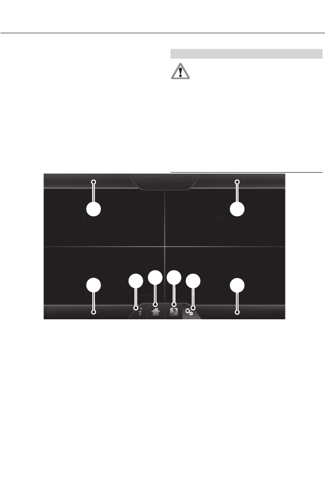
GENERAL INFORMATION WARNING
Driving while distracted can result in
loss of vehicle control, crash and
injury. We strongly recommend that
you use extreme caution when using any
device that may take your focus off the
road. Your primary responsibility is the safe
operation of your vehicle. We recommend
against the use of any handheld device
while driving and encourage the use of
voice-operated systems when possible.
Make sure you are aware of all applicable
local laws that may affect the use of
electronic devices while driving.
AB
HC
DG EF
E161890
PhoneA
Navigation (or Information if your vehicle is not equipped with Navigation)B
ClimateC
SettingsD
EV InformationE
HomeF
InformationG
EntertainmentH
348
MyFord Touch™ (If Equipped)
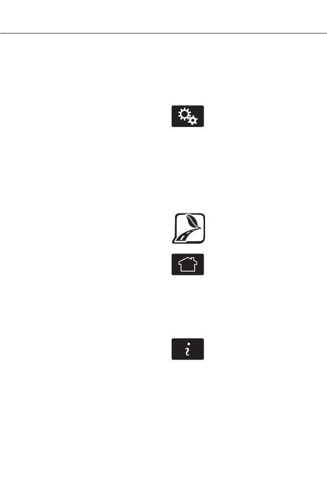
This system uses a four-corner strategy to
provide quick access several vehicle
features and settings. The touchscreen
provides easy interaction with your cellular
phone, multimedia, climate control and
navigation system. The corners display any
active modes within those menus, such as
phone status or the climate temperature.
Note: Some features are not available while
your vehicle is moving.
Note: Your system is equipped with a
feature that allows you to access and
control audio features for 30 minutes after
you switch the ignition off (and no doors
open).
PHONE
Press to select any of the following:
• Phone
• Quick Dial
• Phonebook
• History
• Messaging
• Settings
NAVIGATION
Press to select any of the following:
• My Home
• Favorites
• Previous Destinations
• Point of Interest
• Emergency
• Street Address
• Intersection
• City Center
• Map
• Edit Route Cancel Route
CLIMATE
Press to select any of the following:
• Driver Settings
• Recirculated Air
• Auto
•Dual
• Passenger Settings
•A/C
• Defrost
E142607
SETTINGS
Press to select any of the following:
• Clock
• Display
• Sound
• Vehicle
• Settings
• Help
E161716
EV Information
Press to access features
specific to your hybrid or plug-in
hybrid electric vehicle.
E142613
HOME
Press to access your home
screen. Depending on your
vehicle’s option package and software,
your screens may vary in appearance from
the descriptions in this section. Your
features may also be limited depending on
your market. Check with an authorized
dealer for availability.
E142608
INFORMATION
Press to select any of the following:
• Services
• Travel Link
• Alerts
• Calendar
• Apps
ENTERTAINMENT
349
MyFord Touch™ (If Equipped)

Press to select any of the following:
•AM
•FM
• SIRIUS
•CD
•USB
• BT Stereo
• SD Card
• A/V In
Using the Touch-Sensitive
Controls on Your System
To turn a feature on and off, just touch the
graphic with your finger. To get the best
performance from the touch-sensitive
controls:
• Do not press hard on the controls. They
are sensitive to light touch.
• Use your bare finger to touch the center
of a touch-control graphic. Touching
off-center of the graphic may affect
operation of a nearby control.
• Make sure your hands are clean and
dry.
• Since the touchscreen operates based
on the touch of a finger, you may have
trouble using it if you are wearing
gloves.
• Keep metal and other conductive
material away from the surface of the
touchscreen as this may cause
electronic interference (for example,
inadvertently turning on a feature other
than the one you meant to turn on).
Depending on your vehicle and option
package, you may also have these controls
on your bezel:
• Power: Switch the media or climate
features off and on.
•VOL: Control the volume of playing
media.
• Fan: Control the speed of the climate
system fan.
• Seek and Tune buttons: Use as you
normally would in media modes.
• Eject: Eject a CD from the
entertainment system.
•SOURCE: Touch the word repeatedly
to see all available media modes. The
screen does not change, but you see
the media change in the lower left
status bar.
•SOUND: Touch the word to access the
Sound menu where you can adjust
settings such as: Bass, Treble,
Midrange, Balance and Fade, DSP
(Digital Signal Processing), Occupancy
Mode and Speed Compensated
Volume. (Your vehicle may not have
all of these sound options.)
• Hazard flasher: Switch the hazard
flashers off and on.
Cleaning the Touchscreen Display
Use a clean, soft cloth such as one used
for cleaning glasses. If dirt or fingerprints
are still visible, apply a small amount of
alcohol to the cloth. Do not pour or spray
alcohol onto the display. Do not use
detergent or any type of solvent to clean
the display.
Support
The SYNC support team is available to
help you with any questions you are not
able to answer on your own.
Monday-Saturday, 8:30am-8:00pm EST.
In the United States, call: 1-888-270-1055.
In Canada, call: 1-800-565-3673.
Times are subject to change due to
holidays.
350
MyFord Touch™ (If Equipped)
Safety Information
WARNING
Driving while distracted can result in
loss of vehicle control, crash and
injury. We strongly recommend that
you use extreme caution when using any
device that may take your focus off the
road. Your primary responsibility is the safe
operation of your vehicle. We recommend
against the use of any handheld device
while driving and encourage the use of
voice-operated systems when possible.
Make sure you are aware of all applicable
local laws that may affect the use of
electronic devices while driving.
• Do not attempt to service or repair the
system. See an authorized dealer.
• Do not operate playing devices if the
power cords or cables are broken, split
or damaged. Place cords and cables
out of the way, so they do not interfere
with the operation of pedals, seats,
compartments or safe driving abilities.
• Do not leave playing devices in your
vehicle during extreme conditions as it
could cause them damage. See your
device's user guide for further
information.
• For your safety, some SYNC functions
are speed-dependent. Their use is
limited to when your vehicle is traveling
at speeds under 3 mph (5 km/h).
Make sure that you review your device's
manual before using it with SYNC.
Speed-restricted Features
Some features of this system may be too
difficult to use while your vehicle is moving
so they are restricted from use unless your
vehicle is stationary.
• Screens crowded with information,
such as Point of Interest reviews and
ratings, SIRIUS Travel Link sports
scores, movie times or ski conditions.
• Any action that requires you to use a
keyboard is restricted, such as entering
a navigation destination or editing
information.
• All lists are limited so the user can view
fewer entries (such as phone contacts
or recent phone call entries).
See the following chart for more specific
examples.
Restricted Features
Pairing a Bluetooth phoneCellular Phone
Adding phonebook contacts or uploading phonebook
contacts (from a USB)
List entries are limited for phone contacts and recent
phone call entries
Editing the keypad codeSystem Functionality
Enabling Valet Mode
351
MyFord Touch™ (If Equipped)

Restricted Features
Editing settings while the rear view camera or active park
assist are active
Editing wireless settingsWi-Fi and Wireless
Editing the list of wireless networks
Playing videoVideos, Photos and Graphics
Editing the screen's wallpaper or adding new wallpaper
Composing text messagesText Messages
Viewing received text messages
Editing preset text messages
Using the keyboard to enter a destinationNavigation
Demo navigation route
Adding or editing Address Book entries or Avoid Areas
Privacy Information
When you connect a cellular phone to
SYNC, the system creates a profile within
your vehicle that links to that cellular
phone. This profile helps in offering you
more cellular features and operating more
efficiently. Among other things, this profile
may contain data about your cellular
phone book, text messages (read and
unread), and call history, including history
of calls when your cell phone was not
connected to the system. In addition, if you
connect a media device, the system
creates and retains an index of supported
media content. The system also records a
short development log of approximately
10 minutes of all recent system activity.
The log profile and other system data may
be used to improve the system and help
diagnose any problems that may occur.
The cellular profile, media device index,
and development log remain in your
vehicle unless you delete them and are
generally accessible only in your vehicle
when the cellular phone or media player
is connected. If you no longer plan to use
the system or your vehicle, we recommend
you perform a Master Reset to erase all
stored information.
System data cannot be accessed without
special equipment and access to your
vehicle's SYNC module. Ford Motor
Company and Ford of Canada do not
access the system data for any purpose
other than as described absent consent, a
court order, or where required by law
enforcement, other government
authorities, or other third parties acting
with lawful authority. Other parties may
seek to access the information
independently of Ford Motor Company and
Ford of Canada. For further privacy
information, see the sections on 911 Assist,
Vehicle Health Report, and Traffic,
Directions and Information.
352
MyFord Touch™ (If Equipped)
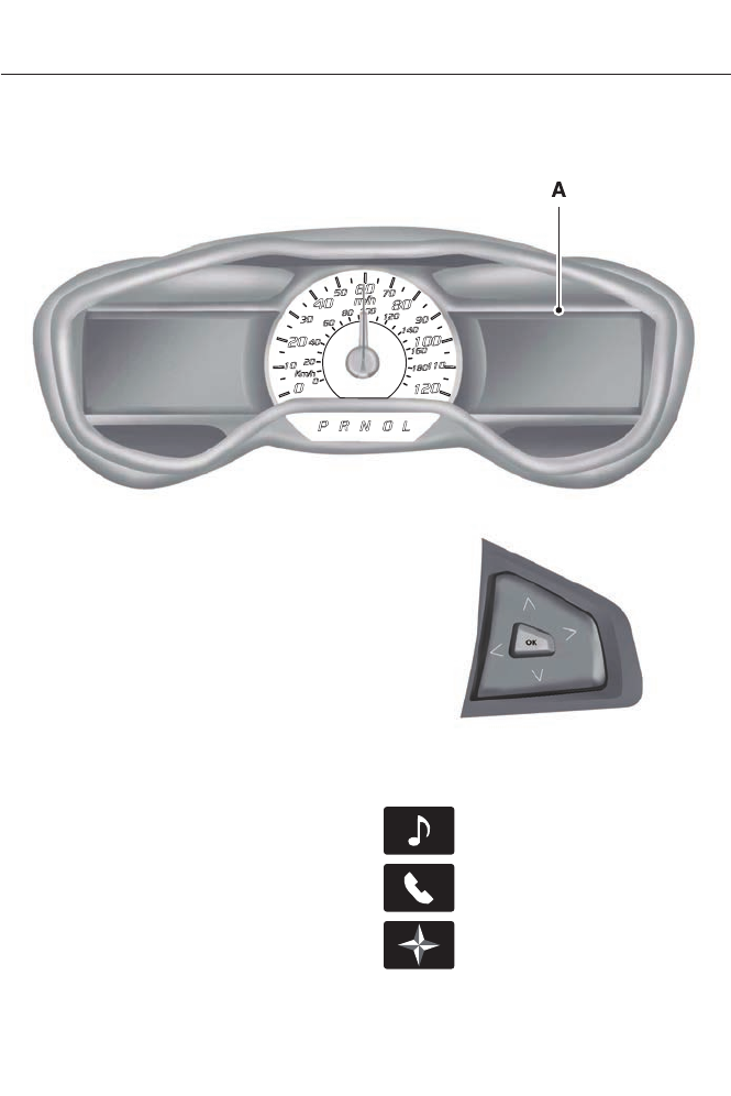
Accessing and Adjusting Modes Through Your Right Vehicle Information
Display
E145459
The display is located on the right side of
your instrument cluster. You can use your
steering wheel controls to view and make
minor adjustments to active modes
without taking your hands off the wheel.
For example:
• In Entertainment mode, you can view
what is now playing, change the audio
source, select memory presets and
make some adjustments.
• In Phone mode, you can accept or
reject an incoming call.
• If your vehicle is equipped with
Navigation, you can view the current
route or activate a route.
• In Efficiency Leaves mode, you can
learn how your vehicle informs you of
your driving efficiency. Press OK to exit
the menu.
E144811
Use the OK and arrow buttons on the right
side of your steering wheel to scroll
through the available modes:
E142611
Entertainment
E142609
Phone
E142610
Navigation
353
MyFord Touch™ (If Equipped)
You can make selections from the menu
by using the OK button. The selection
menu expands and different options
appear.
• Press the up and down arrows to scroll
through the modes.
• Press the right arrow to enter the mode.
• Press the left or right arrows to make
adjustments within the chosen mode.
• Press OK to confirm your selection.
Note: If your vehicle is not equipped with
Navigation, Compass appears in the display
instead of Navigation. If you press the right
arrow to go into the Compass menu, you
can see the compass graphic. The compass
displays the direction in which the vehicle
is traveling, not true direction (for example,
if the vehicle is traveling west, the middle
of the compass graphic displays west; north
displays to the left of west though its true
direction is to the right of west).
Using Voice Recognition
This system helps you control many
features using voice commands. This
allows you to keep your hands on the
wheel and focus on what is in front of you.
The system provides feedback through
audible tones, prompts, questions and
spoken confirmations depending on the
situation and the chosen level of
interaction (voice settings).
The system also asks short questions
(confirmation prompts) when it is not sure
of your request or when there are multiple
possible responses to your request.
When using voice commands, words and
icons may appear in the lower left status
bar indicating the status of the voice
session (such as Listening, Success, Failed,
Paused or Try Again).
How to Use Voice Commands with Your
System
E142599
Press the voice icon. After the
tone, speak your command
clearly.
These commands can be said at any time
during a voice session
"Cancel"
"Exit"
"Go back"
"List of commands"
"Main menu"
"Next page"
"Previous page"
"What can I say?"
"Help"
What Can I Say?
To access the available voice commands
for the current session, do one of the
following:
• During a voice session, press the help
icon (?) in the lower left status bar of
the screen.
• Say, "What can I say?" for an
on-screen listing of the possible voice
commands associated with your
current voice session.
• Press the voice icon. After the tone, say,
"Help" for an audible list of possible
voice commands.
354
MyFord Touch™ (If Equipped)

Helpful Hints
• Make sure the interior of your vehicle is
as quiet as possible. Wind noise from
open windows and road vibrations may
prevent the system from correctly
recognizing spoken commands.
• After pressing the voice icon, wait until
after the tone sounds and Listening
appears before saying a command. Any
command spoken before this does not
register with the system.
• Speak naturally, without long pauses
between words.
• At any time, you can interrupt the
system while it is speaking by pressing
the voice icon.
Accessing a List of Available Commands
• If you use the touchscreen, press the
Settings icon > Help > Voice
Command List.
• If you use the steering wheel control,
press the voice icon. After the tone,
speak your command clearly.
Available voice commands
"Audio list of commands"
"Bluetooth audio list of commands"
"Browse list of commands"
"CD list of commands"
"Climate control list of commands"
"List of commands"
"Navigation list of commands" *
"Phone list of commands"
"Radio list of commands"
"SD card list of commands"
"Sirius satellite list of commands" **
Available voice commands
"Travel link list of commands" *
"USB list of commands"
"Voice instructions list of commands"
"Voice settings list of commands"
"Help"
* This command is only available when
your vehicle is equipped with the
navigation system, and the navigation
system SD card is in the card slot.
** This command is only available when
you have an active SIRIUS satellite radio
subscription.
Voice Settings
Voice settings allow you to customize the
level of system interaction, help and
feedback. The system defaults to standard
interaction that uses candidate lists and
confirmation prompts as these provide the
highest level of guidance and feedback.
•Interaction Mode: Novice mode
provides detailed interaction and
guidance while the advanced mode
has less audible interaction and more
tone prompts.
•Confirmation Prompts: The system
uses these short questions to confirm
your voice request. If turned off, the
system simply makes a best guess as
to what you requested. The system
may still occasionally ask you to
confirm settings.
•Phone and Media Candidate Lists:
Candidate lists are lists of possible
results from your voice commands. The
system creates these lists when it has
the same confidence level of several
options based on your voice command.
355
MyFord Touch™ (If Equipped)

To access these settings using the
touchscreen:
1. Press the Settings icon > Settings >
then Voice Control.
2. Select from the following:
• Interaction Mode
• Confirmation Prompts
• Media Candidate Lists
• Phone Candidate Lists
• Voice Control Volume.
To access these settings using voice
commands:
1. Press the voice icon. Wait for the
prompt "Please say a command".
Another tone sounds to let you know
the system is listening.
2. Say any of the following commands:
Voice settings using voice commands
"Confirmation prompts off"
"Confirmation prompts on"
"Interaction mode advanced"
"Interaction mode novice"
"Media candidate lists off"
"Media candidate lists on"
"Phone candidate lists off"
"Phone candidate lists on"
"Help"
Using Voice Commands with the
Touchscreen Options
Your voice system has a dual mode feature
which allows you to switch between using
voice commands and making on-screen
selections. This is most often available
when using navigation.
Buttons outlined in blue indicate selections
that are part of the dual mode feature. For
example, if while you are in a voice session,
rather than saying the command "Enter
street name" to change the field, you can
press Street and the voice session does
not end. Instead, the voice system changes
to the Street field and asks you to say the
street name. You cannot use the buttons
not outlined in blue as voice commands.
If they are touched during a voice session,
the voice session ends.
For example, you can choose from the
following on the Navigation home screen:
• My Home
• Favorites
• Previous Destinations
• Point of Interest (POI)
• Emergency
• Street Address
• Intersection
• Cancel Route.
Some of the voice commands that are
available while viewing this screen are:
Destination
"Destination emergency"
"Destination favorites"
"Destination intersection"
"Destination my home"
"Destination POI"
"Destination previous destinations"
"Destination street address"
356
MyFord Touch™ (If Equipped)

If you choose Street Address from the
navigation screen, you can choose from
the following:
• Number
• City
• Street Name
• State/Prov.
Some of the voice commands that are
available while viewing this screen are:
Street address
"Enter house number"
"Change house number"
"Enter street name"
"Change street name"
"Enter city"
"Change city"
"Enter state"
"Change state"
If you choose Points of Interest from the
navigation screen, you can choose from
the following:
• Search Area
• Search By Name
• Fuel Station
•ATM
• All Restaurants
• Accommodations
• Parking.
Some of the voice commands that are
available while viewing this screen are:
Points of interest or POI
"Change search area"
"Change state"
"Destination <POI category name>"
"Search by category"
"Search by name"
Note: These are just a sample of the voice
commands available within the Points of
Interest section; the categories themselves
are also technically voice commands.
If you choose Intersection from the
navigation screen, you can choose from
the following:
•1st Street
• 2nd Street
• City
• State/Prov.
Some of the voice commands that are
available while viewing this screen are:
Intersection
"Enter first street name"
"Change first street name"
"Enter second street name"
"Change second street name"
"Enter city"
"Change city"
"Enter state"
"Change state"
357
MyFord Touch™ (If Equipped)
The dual mode feature is also available
when the voice system displays a list of
items to pick from during a voice session,
where you would be able to touch the line
item or say "Line 2". If the system does not
understand a voice command, or there are
multiple options, the system displays a
voice command list for you.
SETTINGS
A
B
C
D
E
F
E161968
ClockA
DisplayB
SoundC
VehicleD
SettingsE
HelpF
E142607
Under this menu, you can set
your clock, access and adjust the
display, sound and vehicle
settings as well as access settings for
specific modes or the help feature.
Clock
Note: You cannot manually set the date.
Your vehicle’s GPS does this for you.
Note: If the battery has been disconnected,
your vehicle needs to acquire a GPS signal
to update the clock. Once your vehicle
acquires the signal, it may take a few
minutes for the update to display the correct
time.
E142607
1. Press the Settings icon > Clock.
358
MyFord Touch™ (If Equipped)
2. Press + and - to adjust the time.
From this screen, you can also make other
adjustments such as 12-hour or 24-hour
mode, activate GPS time synchronization
and have the system automatically update
new time zones.
You can also turn the outside air
temperature display off and on. It appears
at the top center of the touchscreen, next
to the time and date.
The system automatically saves any
updates you make to the settings.
Display
You can adjust the touchscreen display
through the touchscreen or by pressing the
voice button on your steering wheel
controls and when prompted, say, "Display
settings".
E142607
To access and make
adjustments using the
touchscreen, press the Settings
icon > Display.
•Brightness allows you to make the
screen display brighter or dimmer.
•Mode allows you to set the screen to
a certain brightness or have the system
automatically change based on the
outside light level.
• If you select AUTO or NIGHT, you
have the options of turning the
display's Auto Dim feature on or off
and changing the Auto Dim Manual
Offset feature.
•Edit Wallpaper
• You can have your touchscreen
display the default photo or upload
your own.
Uploading Photos for Your Home
Screen Wallpaper
Note: You cannot load photos directly from
your camera. You must access the photos
either from your USB mass storage device
or from an SD card.
Note: Photographs with extremely large
dimensions (such as 2048 x 1536) may not
be compatible and appear as a blank
(black) image on the display.
Your system allows you to upload and view
up to 32 photos.
E142607
To access, press the Settings
icon > Display > Edit
Wallpaper, and then follow the
system prompts to upload your
photographs.
Only the photograph(s), which meets the
following conditions, display:
• Compatible file formats are as follows:
.jpg, .gif, .png, .bmp
• Each file must be 1.5 MB or less.
• Recommended dimensions: 800 x 384
Sound
E142607
Press the Settings icon > Sound,
then select from the following:
Sound settings
Bass
Midrange
Treble
Set Balance and Fade
DSP*
359
MyFord Touch™ (If Equipped)
Sound settings
Occupancy Mode*
Speed Compensated Volume
* Your vehicle may not have this sound
setting.
Vehicle
E142607
Press the Settings icon >
Vehicle, then select from the
following:
• Ambient Lighting
• Vehicle Health Report
• Rear View Camera
• Enable Valet Mode
• Charge Port Light Ring.
Ambient Lighting (If Equipped)
When you turn this feature on, ambient
lighting illuminates footwells and
cupholders with a choice of colors. To
access and make adjustments:
E142607
1. Press the Settings icon > Vehicle >
Ambient Lighting.
2. Touch the desired color.
3. Use the scroll bar to increase or
decrease the intensity.
To turn the feature on or off, press the
power button.
Vehicle Health Report
Turn Automatic Reminders on and off
and set the mileage interval at which you
would like to receive the reports. Press the
? for more information on these selections.
When done making your selections, press
Run Vehicle Health Report Now if you
want your report.
You can find more information on Vehicle
Health Report in this chapter. See
Information (page 402).
Rear View Camera
This menu allows you to access settings
for your rear view camera.
E142607
Press the Settings icon >
Vehicle > Rear View Camera,
then select from the following
settings:
• Rear Camera Delay
• Visual Park Aid Alert
• Guidelines.
You can find more information on the rear
view camera system in another chapter.
See Rear View Camera (page 177).
Enable Valet Mode
Note: If the system locks, and you need to
reset the PIN, enter 3681 and the system
unlocks.
Valet mode allows you to lock the system.
No information is accessible until the
system is unlocked with the correct PIN.
E142607
1. Press the Settings icon > Vehicle >
Enable Valet Mode.
2. When prompted, enter a four-digit PIN.
After you press Continue the system locks
until you enter the PIN again.
Charge Point Light Ring
E142607
Press the Settings icon >
Vehicle > Charge Point Light
Ring, then select from the
following:
360
MyFord Touch™ (If Equipped)
Charge point light ring
Illuminates when plugging in, opening doors, pressing the
unlock button on your remote, and while charging.
On
Does not illuminate.Off
Cord Acknowledgement: Illuminates when plugging in.Limited
Charge Status: Illuminates when opening doors or
pressing the unlock button on your remote.
Note: Details on the charge port light ring
functions are in another chapter. See High
Voltage Battery (page 156).
Settings
Access and adjust system settings, voice
features, as well as phone, navigation and
wireless settings.
System
E142607
Press the Settings icon >
Settings > System, then select
from the following:
System
Select to have the touchscreen display in English, Spanish
or French.
Language
Select to display units in kilometers or miles.Distance
Select to display units in Celsius or Fahrenheit.Temperature
Adjust the volume of voice prompts from the system.System Prompt Volume
Select to have the system beep to confirm choices made
through the touchscreen.
Touch Screen Button Beep
Select to have the system beep to confirm button choices
made through the climate or audio system.
Touch Panel Button Beep
Have the touchscreen keyboard display in QWERTY or
ABC format.
Keyboard Layout
Install any downloaded applications or view the current
software licenses.
Install Applications
Select to restore factory defaults. This erases all personal
settings and personal data.
Master Reset
361
MyFord Touch™ (If Equipped)
Voice Control
E142607
Press the Settings icon >
Settings > Voice Control, then
select from the following:
Voice control
Standard interaction mode provides more detailed inter-
action and guidance. Advanced mode has less audible
interaction and more tone prompts.
Interaction Mode
Have the system ask you short questions if it has not
clearly heard or understood your request.
Confirmation Prompts
Note: Even with confirmation prompts turned off, the
system may occasionally ask you to confirm settings.
Candidate lists are possible results from your voice
commands. The system simply makes a best guess at
your request with these turned off.
Media Candidate Lists
Candidate lists are possible results from your voice
commands. The system simply makes a best guess at
your request with these turned off.
Phone Candidate Lists
This allows you to adjust the system’s voice volume level.Voice Control Volume
Media Player
E142607
Press the Settings icon >
Settings > Media Player, then
select from the following:
362
MyFord Touch™ (If Equipped)
Media player
When this feature is on, the system automatically switches
to the media source upon initial connection. This allows
you to listen to music during the indexing process. When
this feature is off, the system does not automatically
switch to the inserted media source.
Autoplay
Select to connect, disconnect, add or delete a device. You
can also set a device as your favorite so that the system
automatically attempts to connect to that device at every
ignition cycle.
Bluetooth Devices
This allows you to view the version level of the Gracenote
Database.
Gracenote Database Info
With this feature on, the Gracenote Database supplies
metadata information for your music files. This overrides
information from your device. This feature defaults to off.
Gracenote Mgmt
With this feature on, the Gracenote Database supplied
cover art for your music files. This overrides any art from
your device. This feature defaults to Media Player.
Cover Art Priority
Navigation
E142607
Press the Settings icon >
Settings > Navigation, then
select from the following:
Navigation
Turn breadcrumbs on and off.Map Preferences
Have the system display your turn list top to bottom or
bottom to top.
Turn the Parking POI notification on and off.
Have the system display the shortest route, fastest route
or ecological route.
Route Preferences
Have the system avoid freeways.
Have the system avoid tollroads.
Have the system avoid ferries or car trains.
Have the system use HOV (high-occupancy vehicle) lanes.
363
MyFord Touch™ (If Equipped)
Navigation
Have the system use guidance prompts.Navigation Preferences
Have the system automatically fill-in State/Province
information.
Have the system display areas where roadwork occurs.Traffic Preferences
Have the system display incident icons.
Have the system display areas where difficult driving
conditions may occur.
Have the system display areas with snow and ice on the
road may occur.
Have the system display any smog alerts.
Have the system display weather warnings.
Have the system display where there may be reduced
visibility.
Have the system turn on your radio for traffic announce-
ments.
Enter specific areas that would like to avoid on planned
navigation routes.
Avoid Areas
Phone
E142607
Press the Settings icon >
Settings > Phone, then select
from the following:
Phone
Connect, disconnect, add or delete a device, as well as
save it as a favorite.
Bluetooth Devices
Turn Bluetooth on and off.Bluetooth
Have all calls go directly to your voice mail and not ring
inside your vehicle. With this feature turned on, text
message notifications are also suppressed and do not ring
inside your vehicle.
Do Not Disturb
Turn on or turn off the 911 Assist feature. See Information
(page 402).
911 Assist
364
MyFord Touch™ (If Equipped)
Phone
Select the type of notification for phone calls - ring tone,
beep, text to speech, or have it be silent.
Phone Ringer
Select the type of notification for text messages - alert
tone, beep, text to speech, or have it be silent.
Text Message Notification
If compatible with your phone, you can adjust your internet
data connection. Select to make your connection profile
with the personal area network or to turn off your
connection. You can also choose to adjust your settings
or have the system always connect, never connect when
roaming or query on connect. Press ? for more information.
Internet Data Connection
Access features, such as automatic phonebook download,
re-download your phonebook, add contacts from your
phone as well as delete or upload your phonebook.
Manage Phonebook
Have the system alert you when in Roaming mode.Roaming Warning
Wireless & Internet
Your system has a Wi-Fi feature that
creates a wireless network within your
vehicle, thereby allowing other devices
(such as personal computers or phones)
in your vehicle to speak to each other,
share files or play games. Using this Wi-Fi
feature, everyone in your vehicle can also
gain access the internet if you have a USB
mobile broadband connection inside your
vehicle, your phone supports personal area
networking and if you park outside a
wireless hotspot.
E142607
Press the Settings icon >
Settings > Wireless &
Internet, then select from the
following:
365
MyFord Touch™ (If Equipped)

Wi-fi
Wi-Fi Network (Client) Mode turns the Wi-Fi feature on
and off in your vehicle. Make sure you turn it on for
connectivity purposes.
Wi-Fi Settings
Choose a Wireless Network allows you to use a previ-
ously stored wireless network. You can categorize by
alphabetical listing, priority and signal strength. You can
also choose to search for a network, connect to a network,
disconnect from a network, receive more information,
prioritize a network or delete a network.
Gateway (Access Point) Mode makes SYNC an access
point for a phone or a computer when turned on. This
forms the local area network within your vehicle for things,
such as game playing, file transfer and internet browsing.
Press ? for more information.
Gateway (Access Point) Settings allows you to view
and change settings for using SYNC as the internet
gateway.
Gateway (Access Point) Device List allows you to view
recent connections to your Wi-Fi system.
Instead of using Wi-Fi, your system can also use a USB
mobile broadband connection to access the internet. (You
must turn on your mobile broadband device on your
personal computer before connecting it to the system.)
This screen allows you to set up what is your typical area
for your USB mobile broadband connection. (USB mobile
broadband settings may not display if the device is already
on.) You can select the following: Country, Carrier, Phone
Number, User Name and Password.
USB Mobile Broadband
Shows you the currently paired devices as well as giving
you your typical Bluetooth options to connect, disconnect,
set as favorite, delete and add device. Bluetooth is a
registered trademark of the Bluetooth SIG.
Bluetooth Settings
Choose your connection methods and change them as
needed. You can select to Change Order and have the
system either always attempt to connect using a USB
mobile broadband or using Wi-Fi.
Prioritize Connection
Methods
366
MyFord Touch™ (If Equipped)
E142626
The
Wi-Fi
CERTIFIED Logo is a certification mark of
the Wi-Fi Alliance.
Help
E142607
Press the Settings icon > Help,
then select from the following:
Help
View your vehicle's current location, if your vehicle is
equipped with navigation. If your vehicle is not equipped
with navigation, nothing displays.
Where Am I?
Touchscreen system serial numberSystem Information
Your vehicle identification number (VIN)
Touchscreen system software version
Navigation system version
Map database version
Sirius satellite radio ESN
Gracenote Database Information and Library version
View the licenses for any software and applications
installed on your system.
Software Licenses
Certain features are not accessible when your vehicle is
moving.
Driving Restrictions
Turn on and turn off the 911 Assist feature. See Informa-
tion (page 402).
911 Assist
In Case of Emergency (ICE) Quick Dial: allows you to
save up to two numbers as ICE contacts for quick access
if there is an emergency. Select Edit to access your
phonebook and then select the desired contacts. The
numbers then appear as options on this screen for the ICE
1 and ICE 2 buttons. The ICE contacts you select appear
at the end of the 911 Assist call process.
View categorized lists of voice commands.Voice Command List
367
MyFord Touch™ (If Equipped)
To access Help using the voice commands,
press the voice button, then, after the tone,
say "Help". The system provides allowable
voice commands for the current mode.
ENTERTAINMENT
A
B
C
D
E
F
G
H
E161892
AM 1 and AM ASTA
FM 1, FM 2 and FM ASTB
SIRIUSC
CDD
USBE
Touch this button to scroll down for more options, such as SD Card, BT Stereo
and A/V In
F
These buttons change with the media mode you are in.G
Radio memory presets and CD controls.H
Note: Some features may not be available
in your area. Contact an authorized dealer
for more information.
You can access these options using the
touchscreen or voice commands.
Browsing Device Content
When listening to audio on a device, you
can browse through other devices without
having to change sources. For example, if
you are currently listening to audio on an
SD card, you can browse all the artists that
are stored on your USB device.
368
MyFord Touch™ (If Equipped)
E142599
Press the voice icon on the
steering wheel. When prompted,
you can say:
"BROWSE" within devices
"Browse"*
"Browse <league> games"**
"Browse <Sirius category> channels"**
"Browse SD card"
"Browse Sirius channel guide"**
"Browse USB"
"Help"
* If you only say, "Browse", you can then
say any commands in the following chart.
**This command is only usable if you have
an active subscription to SIRIUS satellite
radio.
"BROWSE"
"<League> Games"*
"<Sirius category> channels"*
"SD card"**
"Sirius Channel Guide"*
"USB"**
"Help"
* This command is only usable if you have
an active subscription to SIRIUS satellite
radio.
** For more commands in SD card or USB
mode, see the "SD Card and USB Port"
section of this chapter.
Your voice system allows you to change
audio sources with a simple voice
command. For example, if you are listening
to music on a USB device, then want to
switch to a satellite radio channel, simply
press the voice button on the steering
wheel controls and say the name of the
SIRIUS station (such as, "the Highway").
The following voice commands are
available at the top level of the voice
session no matter which current audio
source you are listening to (such as a USB
device or SIRIUS satellite radio).
Note: This is only available when your
MyFord Touch system language is set to
North American English.
Sample commands
"<87.7-107.9"
"<530-1710>"
"<Channel name>"*
"AM <530-1710>"
"FM <87.7-107.9"
"Play [album] <name>"**
"Play [artist] <name>"**
"Play [genre] <name>"**
"Play [playlist] <name>"**
"Play [song] <name>"**
"Play <name>"
"Play <name (song or album)> by <artist
name>"
369
MyFord Touch™ (If Equipped)

Sample commands
"Sirius <0-223>"*
"Sports games"*
* This command is only usable if you have
an active subscription to SIRIUS satellite
radio.
** The commands that have [ ] around the
word means that the word is optional. For
example, if you say, "Play Metallica", this
is the same as the voice command, "Play
[artist] <name>".
AM/FM Radio
E142611
Touch the AM or FM tab to listen
to the radio.
To change between AM and FM presets,
just touch the AM or FM tab.
Memory Presets
Save a station by pressing and holding one
of the memory preset areas. There is a brief
mute while the radio saves the station.
Sound returns when finished.
HD Radio
Touch this button to turn HD Radio on. The
light on the button illuminates when the
feature is on. HD Radio allows you to
receive radio broadcasts digitally, where
available, providing free, crystal-clear
sound. See HD Radio information later in
this chapter.
Scan
Touch this button to go to the next strong
AM or FM radio station. The light on the
button illuminates when the feature is on.
Options
Sound Settings
Touch this button to adjust settings for:
•Bass
• Midrange
• Treble
• Balance and Fade
• DSP (Digital Signal processing)
• Occupancy Mode
• Speed Compensated Volume.
Note: Your vehicle may not have all these
sound settings.
Set PTY for Seek/Scan
This allows you to select a category of
music you would like to search for. You can
then choose to either seek or scan for the
stations playing that category.
RDS Text Display
This allows you to view the information
broadcast by FM stations.
AST
AST (Autostore) allows you to have the
system automatically store the six
strongest stations in your current location.
TAG Button
This feature is available when HD Radio is
on, and allows you to tag a song to
download later. When you select On, TAG
appears on-screen when HD Radio is
active. You can touch TAG to save the
information of the song that is playing.
When you plug in your portable music
player, the information transfers, if
supported by your device. When you are
connected to iTunes, the tags appear to
remind you of the songs you would like to
download. See HD Radio information later
in this chapter.
370
MyFord Touch™ (If Equipped)

Direct Tune
Touch this button to manually enter the
desired station number. Touch Enter when
you are done.
HD Radio™ Information (If Available)
Note: HD Radio broadcasts are not
available in all markets.
HD Radio technology is the digital
evolution of analog AM/FM radio. Your
system has a special receiver that allows
it to receive digital broadcasts (where
available) in addition to the analog
broadcasts, it already receives. Digital
broadcasts provide a better sound quality
than analog broadcasts with free,
crystal-clear audio and no static or
distortion. For more information, and a
guide to available stations and
programming, please visit
www.hdradio.com.
When HD Radio is on and you tune to a
station broadcasting HD Radio technology,
you may notice the following indicators on
your screen:
E142616
The HD Radio logo blinks when acquiring
a digital station and stays solid when
digital audio is playing. When this logo is
available, you may also see Title and Artist
fields on-screen.
The multicast indicator appears in FM
mode (only) if the current station is
broadcasting multiple digital broadcasts.
The highlighted numbers signify available
digital channels where new or different
content is available. HD1 signifies the main
programming status and is available in
analog and digital broadcasts. Other
multicast stations (HD2 through HD7) are
only available digitally.
TAG allows you to save a song to
download later when you are on an
acquired HD Radio station and the feature
is on. To turn the feature on and use it:
1. Press AM or FM > Options > TAG
Button > On.
2. When you hear a song you like, touch
TAG .
3. The system automatically saves the
song's information and transfers it to
your portable music player (if
supported) when you connect it to the
system. The system automatically
transfers the tag to your player (if
already connected) and a pop-up
confirms the transfer.
4. When you access iTunes with your
portable music player, the tags appear
to you as a reminder. The system
allows you to tag up to approximately
100 songs. For a list of devices that
support tagging, see
www.SYNCMyRide.com,
www.SYNCMyRide.ca or
www.syncmaroute.ca.
371
MyFord Touch™ (If Equipped)

When HD Radio broadcasts are active, you
can access the following functions:
•Scan allows you to hear a brief
sampling of all available stations. This
feature still works when HD Radio
reception is on, although it does not
scan for HD2-HD7 channels. You may
see the HD logo appear if the station
has a digital broadcast.
•Memory presets allow you to save an
active channel as a memory preset.
Touch and hold a memory preset slot
until the sound returns. There is a brief
mute while the radio saves the station.
Sound returns when finished. When
switching to an HD2 or HD3 memory
preset, the sound mutes before the
digital audio plays, because the system
has to reacquire the digital signal.
Note: As with any saved radio station, you
cannot access the saved station if your
vehicle is outside the station’s reception
area.
HD Radio Reception and Station Troubleshooting
Potential reception issues
If you are listening to a multicast station and you are on
the fringe of the reception area, the station may mute due
to weak signal strength.
Reception area
If you are listening to HD1, the system switches back to
the analog broadcast until the digital broadcast is available
again. However, if you are listening to any of the possible
HD2-HD7 multicast channels, the station mutes and stays
muted unless it is able to connect to the digital signal
again.
When the system first receives a station (aside from HD2-
HD7 multicast stations), it first plays the station in the
analog version. Once the receiver verifies the station is an
HD Radio station, it shifts to the digital version. Depending
on the station quality, you may hear a slight sound change
when the station changes from analog to digital. Blending
is the shift from analog to digital sound or digital back to
analog sound.
Station blending
In order to provide the best possible
experience, use the contact form to report
any station issues found while listening to
a station broadcasting with HD Radio
technology. Independent entities own and
operate each station. These stations are
responsible for ensuring all audio streams
and data fields are accurate.
372
MyFord Touch™ (If Equipped)

Potential station issues
ActionCauseIssues
No action required. This is a
broadcast issue.
This is poor time alignment
by the radio broadcaster.
Echo, stutter, skip or repeat
in audio.
Increase or decrease in
audio volume.
No action required. The
reception issue may clear up
as you continue to drive.
The radio is shifting between
analog and digital audio.
Sound fading or blending in
and out.
No action required. This is
normal behavior. Wait until
the audio is available.
The digital multicast is not
available until the HD Radio
broadcast is decoded. Once
decoded, the audio is avail-
able.
There is an audio mute
delay when selecting HD2 or
HD3, multicast preset or
Direct Tune.
No action required. The
station is not available in
your current location.
The previously stored
multicast preset or direct
tune is not available in your
current reception area.
Cannot access HD2 or HD3
multicast channel when
recalling a preset or from a
direct tune.
Fill out the station issue
form at website listed
below.*
Data service issue by the
radio broadcaster.
Text information does not
match currently playing
audio.
Fill out the station issue
form at website listed
below.*
Data service issue by the
radio broadcaster.
There is no text information
shown for currently selected
frequency.
No action required. This is
normal behavior.
Pressing Scan disables
HD2-HD7 channel search.
HD2-HD7 stations not found
when Scan is pressed.
* http://www.ibiquity.com/automotive/report_radio_station_experiences
HD Radio Technology manufactured under
license from iBiquity Digital Corp. U.S. and
foreign patents. HD Radio and the HD and
HD Radio logos are proprietary trademarks
of iBiquity Digital Corp. Ford Motor
Company and iBiquity Digital Corp. are not
responsible for the content sent using HD
Radio technology. Content may be
changed, added or deleted at any time at
the station owner's discretion.
Radio Voice Commands
E142599
If you are listening to the radio,
press the voice button on the
steering wheel controls. When
prompted, say any of the following
commands.
If you are not listening to the radio, press
the voice button and, after the tone, say
"Radio", then any of the following
commands.
373
MyFord Touch™ (If Equipped)

"RADIO"
"<87.9-107.9>"
"<87.9-107.9> HD"1
"<530-1710>"
"AM"
"AM <530-1710>"
"AM autoset"
"AM autoset preset <#>"
"AM preset <#>"
"Browse"2
"FM"
"FM <87.9-107.9>"
"FM <87.9-107.9> HD <#>"1
"FM autoset"
"FM autoset preset <#>"
"FM preset <#>"
"FM 1"
"FM 1 preset <#>"
"FM 2"
"FM 2 preset <#>"
"HD <#>"1
"Preset <#>"
"Radio off"
"Radio on"
"Set PTY"
"RADIO"
"Tune"3
"Help"
1 If available.
2 If you have said "Browse", see the
"Browse" chart later in this section.
3 If you have said "Tune", see the following
"Tune" chart.
"TUNE"
"<530-1710>"
"<87.9-107.9>"
"<87.9-107.9> HD <#>"*
"AM"
"AM <530-1710>"
"AM autoset"
"AM autoset preset <#>"
"AM preset <#>"
"FM"
"FM <87.9-107.9>"
"FM <87.9-107.9> HD <#>"*
"FM autoset"
"FM autoset preset <#>"
"FM preset <#>"
"FM 1"
"FM 1 preset <#>"
"FM 2"
"FM 2 preset <#>"
374
MyFord Touch™ (If Equipped)

"TUNE"
"HD <#>"*
"Preset <#>"
"Help"
* If available.
SIRIUS® Satellite Radio (If
Activated)
E142611
Press the lower left corner of the
touchscreen, and then select the
SIRIUS tab.
Memory Presets
Save a channel by pressing and holding
one of the memory preset areas. There is
a brief mute while the radio saves the
channel. Sound returns when finished.
ALERT
Save the current song, artist, or team as a
favorite. The system alerts you when it
plays again on any channel.
Replay
Replay audio on the current channel. You
can replay approximately 45 minutes of
audio as long as you have remained tuned
to the current station. Changing stations
erases the previous audio.
While in replay mode:
• Press and release the seek buttons to
hear the previous or next song.
• Press and hold the seek buttons to
reverse or fast forward in the current
track.
• Press play or pause to play or pause
the audio.
• Press Replay to return to live audio if
you have been using the feature to
replay audio.
Scan
Touch this button to hear a brief sampling
of channels.
Options
Touch this button to view and adjust
various media settings.
Sound Settings
Touch this button to adjust settings for:
•Bass
• Midrange
• Treble
• Balance and Fade
• DSP (Digital Signal processing)
• Occupancy Mode
• Speed Compensated Volume.
Note: Your vehicle may not have all these
sound settings.
Set Category for Seek/Scan
This allows you to select a category of
music you would like to search for. You can
then choose to either seek or scan for the
stations playing that category.
Parental Lockout
This allows you to lock and unlock
channels, change or reset your PIN or
unlock all channels. To use this feature,
you need your initial PIN, which is 1234.
Artist/Title/Team Alerts
This feature allows you to select Artists,
Titles and Teams that you would like the
system to alert you to when they are
playing on other channels. Press Edit Alerts
to delete or turn off alerts. You can also
set all alerts to on or off. When an alert
appears on the screen, you can choose to
375
MyFord Touch™ (If Equipped)

Tune to the channel, to Cancel the alert or
to Disable Alerts. If you are listening to a
sporting event, you can save your favorite
teams so that the system can alert you
when they are playing on a satellite radio
channel.
Note: SIRIUS does not support the Alert
feature on all channels. Ford Motor
Company shall not be responsible for Alert
feature variation.
Electronic Serial Number (ESN)
SIRIUS requires this number when
communicating with you about your
account.
Direct Tune
Touch this button to manually enter the
desired satellite channel number. Touch
Enter when you are done.
Browse
Touch this button to view a list of all
available stations. Scroll to see more
categories. Touch the station you want to
listen to.
Touch Skip if you want to skip this
channel.
Touch Lock if you do not want anyone to
listen to this channel.
Touch Title or Artist to see song and
artists on other stations.
SIRIUS Satellite Radio Information
Note: SIRIUS reserves the unrestricted right
to change, rearrange, add or delete
programming including canceling, moving
or adding particular channels, and its prices,
at any time, with or without notice to you.
Ford Motor Company shall not be
responsible for any such programming
changes.
E142593
SIRIUS satellite radio is a
subscription-based satellite radio service
that broadcasts a variety of music, sports,
news, weather, traffic and entertainment
programming. Your factory-installed
SIRIUS satellite radio system includes
hardware and a limited subscription term
that begins on the date of sale or lease of
your vehicle. See an authorized dealer for
availability.
For more information on extended
subscription terms (a service fee is
required), the online media player and a
list of SIRIUS satellite radio channels, and
other features, please visit
www.siriusxm.com in the United States,
www.sirius.ca in Canada, or call SIRIUS at
1-888-539-7474.
Note: This receiver includes the eCos
real-time operating system. eCos is
published under the eCos License.
Satellite Radio Electronic Serial Number
(ESN)
You need your ESN to activate, modify or
track your satellite radio account. The ESN
is on the System Information Screen (SR
ESN:XXXXXXXXXXXX). To access your
ESN, touch the bottom left corner of the
touchscreen. Touch SIRIUS > Options.
376
MyFord Touch™ (If Equipped)

SIRIUS Satellite Radio Reception Factors and Troubleshooting
Potential reception issues
For optimal reception performance, keep the antenna
clear of snow and ice build-up and keep luggage and other
materials as far away from the antenna as possible.
Antenna obstructions
Hills, mountains, tall buildings, bridges, tunnels, freeway
overpasses, parking garages, dense tree foliage and
thunderstorms can interfere with your reception.
Terrain
When you pass a ground-based broadcast-repeating
tower, a stronger signal may overtake a weaker one and
the audio system may mute.
Station overload
Your display may show ACQUIRING... to indicate the
interference and the audio system may mute.
Satellite radio signal interfer-
ence
Troubleshooting tips
ActionCauseRadio display
No action required. This
message should disappear
shortly.
Radio requires more than
two seconds to produce
audio for the selected
channel.
Acquiring...
If this message does not
clear shortly, or with an igni-
tion key cycle, your receiver
may have a fault. See an
authorized dealer for service.
There is an internal module
or system failure present.
Sat Fault/SIRIUS System
Failure.
Tune to another channel or
choose another preset.
The channel is no longer
available.
Invalid Channel.
Contact SIRIUS at 1-888-
539-7474 to subscribe to
the channel, or tune to
another channel.
Your subscription does not
include this channel.
Unsubscribed Channel.
The signal is blocked. When
you move into an open area,
the signal should return.
The signal is lost from the
SIRIUS satellite or SIRIUS
tower to your vehicle
antenna.
No Signal.
377
MyFord Touch™ (If Equipped)
Troubleshooting tips
ActionCauseRadio display
No action required. The
process may take up to
three minutes.
Update of channel
programming in progress.
Updating.
Contact SIRIUS at 1-888-
539-7474 to resolve
subscription issues.
Your satellite service is no
longer available.
Call SIRIUS
1-888-539-7474.
Use the channel guide to
turn off the Lock or Skip
function on that station.
All the channels in the
selected category are either
skipped or locked.
None found. Check Channel
Guide.
No action required.SIRIUS has updated the
channels available for your
vehicle.
Subscription Updated.
SIRIUS Satellite Radio Voice
Commands
E142599
If you are listening to SIRIUS
satellite radio, press the voice
button on the steering wheel
controls. When prompted, say any of the
following commands.
If you are not listening to SIRIUS satellite
radio, press the voice button and, after the
tone, say "SIRIUS", then any of the
following commands.
"SIRIUS"
"<Channel name>"
"Preset <#>"
"SAT"
"SAT preset <#>"
"SAT 1"
"SAT 1 Preset <#>"
"SAT 2"
"SIRIUS"
"SAT 2 preset <#>"
"SAT 3"
"SAT 3 preset <#>"
"Sirius <0-223>"
"Sirius off"
"Sirius on"
"Sports game"*
"Tune"**
"Help"
* If you have said "Sports game", see the
following "Sports game" chart.
** If you have said "Tune", see the following
"Tune" chart.
378
MyFord Touch™ (If Equipped)
"SPORTS GAME"
"Tune to the <college name> game"
"Tune to the <team city> game"
"Tune to the <team city> <team name>
game"
"Tune to the <team name> game"
"Help"
"TUNE"
"<Channel Name>"
"Preset <#>"
"SAT"
"SAT 1"
"SAT 1 preset <#>"
"SAT 2"
"SAT 2 preset <#>"
"SAT 3"
"SAT 3 preset <#>"
"Sirius <0-223>"
"Help"
CD
E142611
Press the lower left corner of the
touchscreen, and then select the
CD tab.
You can also advance and reverse the
current track or current folder, if applicable.
Repeat
Touch this button to repeat the currently
playing track, all tracks on the disc or turn
the feature off if already on.
Shuffle
Touch this button to play the tracks or
entire albums in random order, or turn the
feature off if already on.
Scan
Touch this button to hear a brief sampling
of all available tracks.
More Info
Touch this button to see disc information.
Options
Sound Settings
Touch this button to adjust settings for:
•Bass
• Midrange
• Treble
• Balance and Fade
• DSP (Digital Signal processing)
• Occupancy Mode
• Speed Compensated Volume.
Note: Your vehicle may not have all these
sound settings.
Compression
Touch this button to turn the compression
feature on and off.
Browse
Touch this button to look through all
available CD tracks.
CD Voice Commands
E142599
If you are listening to a CD, press
the voice button on the steering
wheel controls. When prompted,
say any of the following commands.
If you are not listening to a CD, press the
voice button and, after the tone, say "CD",
then any of the following commands.
379
MyFord Touch™ (If Equipped)
"CD"
"Pause"
"Play"
"Play next track"
"Play previous track"
"Play track <1-512>"
"Repeat"
"Repeat folder"*
"Repeat off"
"Repeat track"
"Shuffle"
"Shuffle CD"*
"Shuffle folder"*
"Shuffle off"
"Help"
*This applies to WMA or MP3 files only.
SD Card Slot and USB Port
SD Card
Note: Your SD card slot is spring-loaded.
To remove the SD card, press the card in
and the system ejects it. Do not attempt to
pull the card to remove it as this could cause
damage.
Note: The navigation system also uses this
card slot. See Navigation (page 414).
E142619
The SD card slot is located either in the
center console or behind a small access
door in the instrument panel. To access
and play music from your device, press the
lower left corner of the touchscreen.
E142620
SD logo is a trademark of SD-3C, LLC.
USB Port
E142621
The USB ports are located either in the
center console or behind a small access
door in the instrument panel. To access
and play music from your device, press the
lower left corner of the touchscreen.
380
MyFord Touch™ (If Equipped)

This feature allows you to plug in media
playing devices, memory sticks, flash drives
or thumb drives, and charge devices if they
support this feature.
In order to playback video from your iPod
or iPhone, you must have a special
combination USB/RCA composite video
cable (which you can buy from Apple).
When you connect the cable to your iPod
or iPhone, plug the other end into both the
RCA jacks and the USB port.
Playing Music from Your Device
E142611
Insert your device and select the
SD Card or USB tab once the
system recognizes it. You can
then select from the following options:
Repeat
This feature replays the currently playing
song or album.
Shuffle
Touch this button to play music on the
selected album or folder in random order.
Similar Music
This feature allows you to choose music
similar to what is currently playing.
More Info
Touch this button to see disc information
such as current track, artist name, album
and genre.
Options
Touch this button to view and adjust
various media settings.
Sound Settings allows you to adjust
settings for:
•Bass
• Midrange
• Treble
• Balance and Fade
• DSP (Digital Signal processing)
• Occupancy Mode
• Speed Compensated Volume.
Note: Your vehicle may not have all these
sound settings.
Media Player Settings allows you to
select more settings, which is under Media
Player. See Settings (page 358).
Device Information displays software
and firmware information about the
currently connected media device.
Update Media Index indexes your device
when you connect it for the first time and
each time the content changes (such as
adding or removing tracks) to make sure
you have the latest voice commands
available for all media on the device.
Browse
This feature allows you to view the
contents of the device. It also allows you
to search by categories, such as genre,
artist or album.
If you want to view song information such
as Title, Artist, File, Folder, Album, and
Genre, touch the on-screen album art.
You can also touch What’s Playing to
hear how the system pronounces the
current band and song. This can be helpful
when using voice commands to make sure
the system correctly plays your request.
Playing Video from Your Device
To access and play video from your device,
your vehicle's transmission must be in
position P with the ignition in accessory
mode. See Starting and Stopping the
Engine (page 132).
381
MyFord Touch™ (If Equipped)
SD Card and USB Voice Commands
E142599
If you are listening to a USB
device or an SD card, press the
voice button on the steering
wheel controls. When prompted, say any
of the following commands.
If you are not listening to a USB device or
an SD card, press the voice button and,
after the tone, say "USB" or "SD card",
then any of the following commands.
"USB" or "SD CARD"
"Browse"*
"Next"
"Pause"
"Play"
"Play album <name>"
"Play all"
"Play artist <name>"
"Play audiobook <name>"
"Play author <name>"
"Play composer <name>"
"Play folder <name>"
"Play genre <name>"
"Play movie <name>"**
"Play music video <name>"**
"Play playlist <name>"
"Play podcast <name>"
"Play podcast episode <name>"
"Play similar music"
"Play song <name>"
"USB" or "SD CARD"
"Play TV show <name>"**
"Play TV show episode <name>"**
"Play video <name>"**
"Play video podcast <name>"**
"Play video podcast episode <name>"**
"Play video playlist <name>"**
"Previous"
"Repeat all"
"Repeat off"
"Repeat one"
"Shuffle"
"Shuffle album"
"Shuffle off"
"What's this?"
"Help"
* If you have said you would like to browse
your USB or SD card, the system prompts
you to specify what you would like to
browse. When prompted, see the following
"Browse" chart.
** These commands are only available in
USB mode and are device-dependent.
"BROWSE"
"Album <name>"
"All albums"
"All artists"
"All audiobooks"
382
MyFord Touch™ (If Equipped)

"BROWSE"
"All authors"
"All composers"
"All folders"
"All genres"
"All movies"*
"All music videos"*
"All playlists"
"All podcasts"
"All songs"
"All TV shows"*
"All video playlists"*
"All video podcasts"*
"All videos"*
"Artist <name>"
"Audiobook <name>"
"Author <name>"
"Composer <name>"
"Folder <name>"
"Genre <name>"
"Playlist <name>"
"Podcast <name>"
"TV show <name>"*
"Video <name>"*
"Video playlist <name>"*
"BROWSE"
"Video podcast <name>"*
"Help"
* This command is only available in USB
mode and is device-dependent.
Supported Media Players, Formats
and Metadata Information
SYNC is capable of hosting nearly any
digital media player, including iPod,
Zune™, plays from device players, and
most USB drives. Supported audio formats
include MP3, WMA, WAV and AAC.
It is also able to organize your indexed
media from your playing device by
metadata tags. Metadata tags, which are
descriptive software identifiers embedded
in the media files, provide information
about the file.
If your indexed media files contain no
information embedded in these metadata
tags, SYNC may classify the empty
metadata tags as Unknown.
In order to playback video from your iPod
or iPhone, you must have a special
combination USB/RCA composite video
cable (which you can buy from Apple).
When you connect the cable to your iPod
or iPhone, plug the other end into both the
RCA jacks and the USB port.
Bluetooth Audio
Your system allows you to stream audio
over your vehicle's speakers from your
connected, Bluetooth-enabled cellular
phone.
E142611
To access, press the lower left
corner on the touchscreen, then
select the BT Stereo tab.
383
MyFord Touch™ (If Equipped)
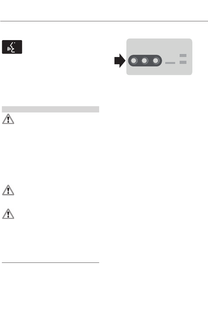
Bluetooth Audio Voice Commands
E142599
If you are listening to a Bluetooth
audio device, press the voice
button on the steering wheel
control. When prompted, say "Next song",
"Pause", "Play" or "Previous song".
If you are not listening to a Bluetooth audio
device, press the voice button and, after
the tone, say "Next song", "Pause", "Play"
or "Previous song".
A/V Inputs
WARNINGS
Driving while distracted can result in
loss of vehicle control, crash and
injury. We strongly recommend that
you use extreme caution when using any
device that may take your focus off the
road. Your primary responsibility is the safe
operation of your vehicle. We recommend
against the use of any handheld device
while driving and encourage the use of
voice-operated systems when possible.
Make sure you are aware of all applicable
local laws that may affect the use of
electronic devices while driving.
For safety reasons, do not connect
or adjust the settings on your
portable music player while your
vehicle is moving.
Store the portable music player in a
secure location, such as the center
console or the glove box, when your
vehicle is in motion. Hard objects may
become projectiles in a crash or sudden
stop, which may increase the risk of serious
injury. The audio extension cable must be
long enough to allow the portable music
player to be safely stored while your
vehicle is moving.
E142622
Your A/V inputs allow you to connect an
auxiliary audio/video source (such as a
gaming systems or a personal camcorder)
by connecting RCA cords (not included)
to these input jacks. The jacks are yellow,
red and white and are located either
behind a small access door on the
instrument panel or in your center console.
You can also use the A/V inputs as an
auxiliary input jack to play music from your
portable music player over your vehicle's
speakers. Plug in your 1/8 inch (3.5
millimeter) RCA adapter into the two left
A/V input jacks (red and white).
Press the lower left corner of the
touchscreen, and then select A/V In.
To use the auxiliary input jack feature,
make sure that your portable music player
is designed for use with headphones and
that it is fully charged. You also need an
audio extension cable with stereo male
1/8-inch (3.5 millimeter) connectors at one
end and a RCA jack at the other.
1. Switch off the vehicle, radio and
portable music player. Set the parking
brake and put the transmission in
position P.
2. Attach one end of the audio extension
cable to the headphone output of your
player and the other end into the
adapter in one of the two left A/V input
jacks (white or red) inside the center
console.
384
MyFord Touch™ (If Equipped)
3. Press the lower left corner on the
touchscreen. Select either a tuned FM
station or a CD (if there is a CD already
loaded into the system).
4. Adjust the volume as desired.
5. Turn the portable music player on and
adjust the volume to ½ the maximum.
6. Press the lower left corner on the
touchscreen. Select the A/V In tab.
(You should hear audio from your
portable music player although it may
be low.)
7. Adjust the sound on your portable
music player until it reaches the level
of the FM station or CD by switching
back and forth between the controls.
In order to playback video from your iPod
or iPhone, you must have a special
combination USB/RCA composite video
cable (which you can buy from Apple).
When you connect the cable to your iPod
or iPhone, plug the other end into both the
RCA jacks and the USB port.
Troubleshooting
• Do not connect the audio input jack to
a line level output. The jack only works
correctly with devices that have a
headphone output with a volume
control.
• Do not set the portable music player's
volume level higher than is necessary
to match the volume of the CD or FM
radio as this causes distortion and
reduces sound quality.
• If the music sounds distorted at lower
listening levels, turn the portable music
player volume down. If the problem
persists, replace or recharge the
batteries in the portable media player.
• Control the portable media player in
the same manner when used with
headphones, as the auxiliary input jack
does not provide control (such as Play
or Pause) over the attached portable
media player.
PHONE
A
B
C
D
E
F
E161968
385
MyFord Touch™ (If Equipped)
PhoneA
Quick DialB
PhonebookC
HistoryD
MessagingE
SettingsF
Hands-free calling is one of the main
features of SYNC®. Once you pair your
phone, you can access many options using
the touchscreen or voice commands. While
the system supports a variety of features,
many are dependent on your cellular
phone’s functionality.
At a minimum, most cellular phones with
Bluetooth wireless technology support the
following functions:
• Answering an incoming call
• Ending a call
• Using privacy mode
• Dialing a number
• Redialing
• Call waiting notification
• Caller ID.
Other features, such as text messaging
using Bluetooth and automatic phonebook
download, are phone-dependent features.
To check your phone’s compatibility, see
your phone’s user manual and visit
www.SYNCMyRide.com,
www.SYNCMyRide.ca or
www.syncmaroute.ca.
Pairing Your Phone for the First
Time
WARNING
Driving while distracted can result in
loss of vehicle control, crash and
injury. We strongly recommend that
you use extreme caution when using any
device that may take your focus off the
road. Your primary responsibility is the safe
operation of your vehicle. We recommend
against the use of any handheld device
while driving and encourage the use of
voice-operated systems when possible.
Make sure you are aware of all applicable
local laws that may affect the use of
electronic devices while driving.
The first thing you must do to use the
phone features of SYNC is to pair your
Bluetooth-enabled cellular phone with
SYNC. This allows you to use your phone
in a hands-free manner.
Note: Put the transmission in position P.
Turn on your vehicle ignition and the radio.
1. Touch Add Phone in the upper left
corner of the touchscreen. Find SYNC
appears on the screen, and instructs
you to begin the pairing process from
your device.
2. Make sure that Bluetooth is set to On
and that your cellular phone is in the
proper mode. See your phone’s manual
if necessary.
386
MyFord Touch™ (If Equipped)
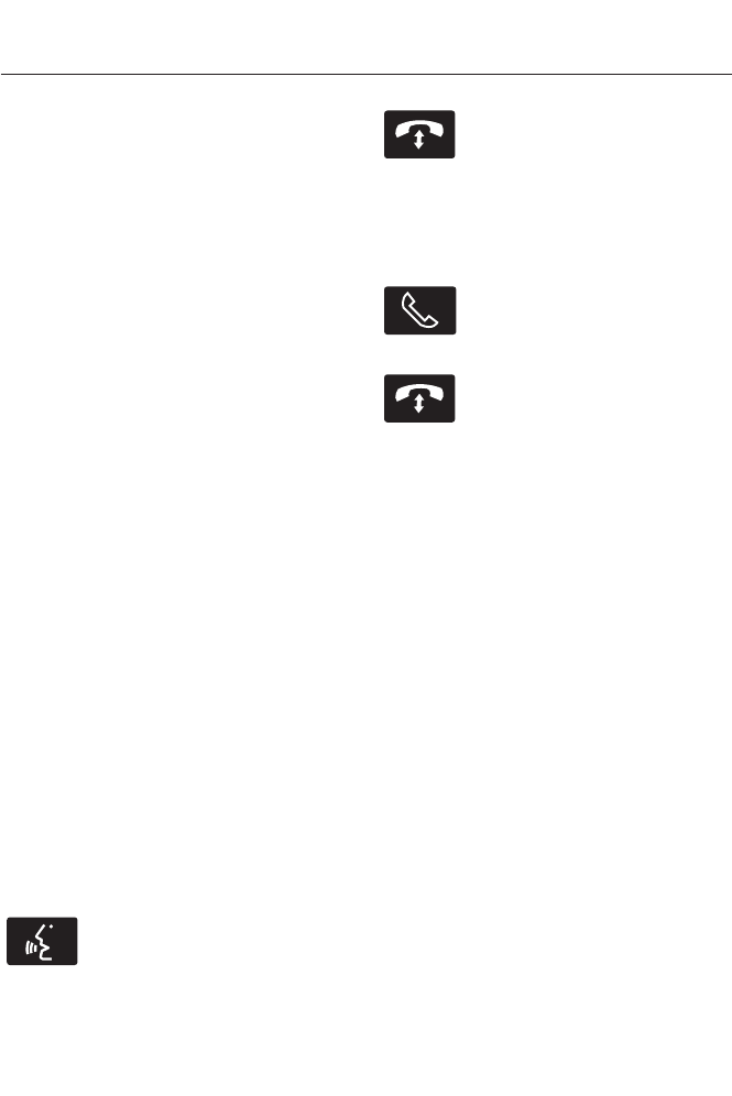
Note: Select SYNC, and a six-digit PIN
appears on your device.
3. If you are prompted to enter a PIN on
your device, it does not support Secure
Simple Pairing. To pair, enter the PIN
displayed on the touchscreen. Skip the
next step.
4. When prompted on your phone’s
display, confirm that the PIN provided
by SYNC matches the PIN displayed
on your cellular phone.
5. The display indicates when the pairing
is successful.
SYNC may prompt you with more phone
options. For more information on your
phone's capability, see your phone's
manual and visit the website.
Pairing Subsequent Phones
Note: Put the transmission in position P.
Turn on your vehicle ignition and the radio.
1. Press the Phone corner of the
touchscreen > Settings > BT Devices
> Add Device.
2. Make sure that Bluetooth is set to On
and that your cellular phone is in the
proper mode. See your phone's manual
if necessary.
3. When prompted on your phone's
display, enter the six-digit PIN provided
by SYNC on the screen. The display
indicates when the pairing is
successful.
SYNC may prompt you with more phone
options. For more information on your
phone's capability, see your phone's
manual and visit the website.
Making Calls
E142599
Press the voice button on your
steering wheel controls. When
prompted, say, "Call <name>"
or say "Dial", then the desired number.
E142632
To end the call or exit phone
mode, press and hold the phone
button.
Receiving Calls
During an incoming call, an audible tone
sounds. Call information appears in the
display if it is available.
Accept the call by pressing
Accept on the touchscreen or
by pressing this phone button on
your steering wheel controls.
E142632
Reject the call by pressing
Reject on the touchscreen or by
pressing and holding this phone
button on your steering wheel controls.
Ignore the call by doing nothing. SYNC logs
it as a missed call.
Phone Menu Options
Press the top left corner on your
touchscreen to select from the following
options:
Phone
Touch this button to access the on-screen
numerical pad to enter a number and place
a call. During an active call, you can also
choose to:
• Mute the call
• Put the call on hold
• Turn on the privacy feature
• Join two calls
• End the call.
Quick Dial
Set up favorite contacts from you
phonebook or history folder.
387
MyFord Touch™ (If Equipped)

Phonebook
Touch this button to access and call any
contacts in your previously downloaded
phone book. The system places the entries
in alphabetical categories summarized at
the top of the screen.
To turn on contact picture settings, if your
device supports this feature, press Phone
> Settings > Manage Phonebook >
Download photos from Phonebook >
On.
Certain smartphones may support
transferring street addresses when listed
with phone book contact information. If
your phone supports this feature, you can
select and use these addresses as
destinations and save them as favorites.
History
After you connect your Bluetooth-enabled
phone to SYNC, you can access any
previously dialed, received or missed calls.
You can also choose to save these to your
Favorites or to Quick Dial.
Note: This is a phone-dependent feature.
If your phone does not support downloading
call history using Bluetooth, SYNC keeps
track of calls made with the SYNC system.
Messaging
Send text messages using your
touchscreen. See Text messaging later
in this section.
Settings
Touch this button to access various phone
settings, such turning Bluetooth on and off,
managing your phonebook and more. See
Phone settings later in this section.
Text Messaging
Note: Downloading and sending text
messages using Bluetooth are
phone-dependent features.
Note: Certain features in text messaging
are speed-dependent and not available
when your vehicle is traveling at speeds over
3 mph (5 km/h).
Note: SYNC does not download read text
messages from your phone.
You can send and receive text messages
using Bluetooth, read them aloud and
translate text messaging acronyms, such
as LOL.
1. Touch the top left corner of the display
to access the Phone menu.
2. Select Messaging.
3. Choose from the following:
• Listen (speaker icon)
• Dial
• Send Text
• View
• Delete.
Composing a Text Message
Note: This is a speed-dependent feature.
It is unavailable when your vehicle is
traveling at speeds over 3 mph (5 km/h).
Note: Downloading and sending text
messages using Bluetooth are
phone-dependent features.
1. Touch the top left corner of the display
to access the Phone menu.
2. Touch Messaging > Send Text.
3. Enter a phone number or choose from
your phonebook.
4. You can select from the following
options:
•Send, which sends the message as it
is.
•Edit Text, which allows you to
customize the pre-defined message or
create a message on your own.
388
MyFord Touch™ (If Equipped)

You can then preview the message, verify
the recipient as well as update the
message list, and send it to a connected
device (such as a USB drive).
Text message options
I’ll call you back in a few minutes.
I just left, I’ll be there soon.
Can you give me a call?
I’m on my way.
I’m running a few minutes late.
I’m ahead of schedule, so I’ll be there early.
I’m outside.
I’ll call you when I get there.
OK
Yes
No
Thanks
Stuck in traffic.
Call me later.
LOL
Receiving a Text Message
Note: If you select View and your vehicle is
traveling over 3 mph (5 km/h), the system
offers to read the message to you instead
of allowing you to view it while driving.
When a new message arrives, an audible
tone sounds and the screen displays a
pop-up with the caller name and ID, if
supported by your phone. You can press:
•View to view the text message.
•Listen for SYNC to read the message
to you.
•Dial to call the contact.
•Ignore to exit the screen.
Phone Settings
Press Phone > Settings.
Bluetooth Devices
Touch this tab to connect, disconnect, add
or delete a device, as well as save it as a
favorite.
Bluetooth
Touch this tab to turn Bluetooth off or on.
389
MyFord Touch™ (If Equipped)
Do Not Disturb
Touch this tab if you want all calls to go
directly to your voice mail and not ring in
the vehicle. When this feature is on, text
message notifications do not ring inside
the cabin either.
911 Assist
Turn on or turn off the 911 Assist feature.
See Information (page 402).
Phone Ringer
Select the ring tone you want to hear when
you receive a call. Choose from possible
system ring tones, your currently paired
phone’s ring tone, a beep, text-to-speech
or a silent notification.
Text Message Notification
Select a text message notification, if
supported by your phone. Choose from
possible system alert tones,
text-to-speech or silent.
Internet Data Connection
If your phone is compatible, use this screen
to adjust your internet data connection.
Select to make your connection profile
with the personal area network or to turn
off your connection. You can also choose
to adjust your settings or have the system
always connect, never connect when
roaming or query on connect. Press ? for
more information.
Manage Phonebook
Touch this button to access features such
as automatic phonebook download,
re-download your phonebook, add
contacts from your phone as well as delete
or upload your phonebook.
Roaming Warning
Touch this button to have the system alert
you when your phone is in roaming mode.
Phone Voice Commands
E142599
Press the voice button on the
steering wheel controls. When
prompted, say any of the
following commands:
"PHONE"
"Join calls"*
"Call"
"Listen to text message <#>""Call <name>"
"Listen to text messages""Call <name> at home"
"Messages"**
"Call <name> at work"
"Mute call"*
"Call <name> on cell"
"Pair phone""Call <name> on other"
"Privacy on"*
"Call voicemail"
"Read text message""Dial"
390
MyFord Touch™ (If Equipped)

"PHONE"
"Reply to text messages""Do not disturb off"
"Turn ringer off""Do not disturb on"
"Turn ringer on""Forward text messages"
"Unmute call"*
"Go to hands free"*
"Help"
"Hold call off"*
"Hold on"*
* These commands are only available during an active call.
** If you say "Messages", see the following "Messages" chart for additional commands.
"MESSAGES"
"Call"
"Forward text messages"
"Listen to text message <#>"
"Listen to text messages"
"Reply to text messages"
"Help"
ELECTRIC VEHICLE
INFORMATION
E161716
Your system has special electric
vehicle screens, which display
power flow and charge settings.
To access these screens, press
the EV Info button.
391
MyFord Touch™ (If Equipped)
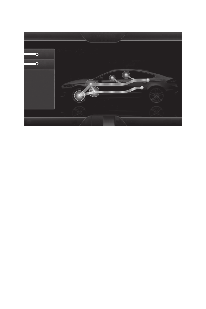
E162199
A
B
SettingsA
PowerB
Settings (Energi Only)
This screen allows you to set up the
charging convenience features.
Note: You can also set up the charging
convenience features using MyFord Mobile
over the internet or smartphone application.
For more information on MyFord Mobile, and
to set up your MyFord Mobile account, visit
www.myfordmobile.com.
To improve the charging experience, your
vehicle has the following convenience
features:
•Value Charge: Your vehicle schedules
its charging time when the utility rates
are lowest. Contact your utility
company to see what rates are
available.
•Charge Now: Your vehicle starts
charging immediately after you
connect the charging plug to your
vehicle.
•My GO Time: Setting the My GO Time
allows you to control charging
schedules and cabin conditioning
settings so your vehicle is ready to drive
when you are. By setting a My GO Time,
your vehicle can use your value charge
settings to optimize charging and have
a complete charge before your next set
drive time. A calendar view allows you
to program two My GO Times per day
for each day of the week.
392
MyFord Touch™ (If Equipped)
Note: Remember, you must plug in your
vehicle for My GO Time to work.
•Cabin Conditioning: Get the most
miles out of every charge by
conditioning your vehicle while it is
plugged in. Set the cabin temperature
when you set your My GO Time so you
use energy from your home (or
charging station) instead of your
vehicle’s battery.
BA
CD
E161966
My GO Time summary displays the next My GO Time and cabin temperature
setting.
A
Estimated charge time limits displays the estimated minimum and maximum
times to fully charge the high-voltage battery and the battery’s current charge
as a percentage.
B
Charge profile and mode displays the current charging profile and charging
mode.
C
Charging status and actual times displays charging status with the charging
start time, end time, and duration.
D
My GO Time Summary
GO Time
This is the time and date of your next set
drive time. Your vehicle automatically
schedules charging and cabin conditioning
to finish by this time.
Temperature
This is the chosen cabin conditioning
setting for this My GO Time.
393
MyFord Touch™ (If Equipped)

Skip
This cancels the cabin conditioning for the
present My GO Time. Once you touch Skip,
the GO Time and Temperature grey out,
and the LED illuminates on the Skip button.
Touch the button again to turn on the
cabin conditioning. This feature allows you
to ignore the present GO Time without
having to delete the My GO Time or turning
off the entire schedule (see GO Time
Schedule later in this section). After the
present GO Time passes, the Skip feature
resets.
Edit
This accesses your My GO Time Schedule
(see GO Time Schedule later in this
section).
The system also alerts you to any conflicts
by highlighting areas of the screen in
yellow. If your battery cannot have a full
charge by the scheduled drive time, the
system highlights the current My GO Time
and Actual Charge End Time and a
message Charge at GO Time: under
100% appears. This is normal; the vehicle
is informing you of the conflicting situation.
This notification only displays when the
gearshift selector lever is in position P.
Note: Charging occurs as soon as you plug
the vehicle in. The system limits cabin
conditioning to 15 minutes before the My
GO Time.
To eliminate the conflict notification
immediately or to prevent a conflict in the
future, try the following:
• Change the present My GO Time to
occur later.
• Plug the vehicle into a 240V charging
station instead of 120V convenience
cord. Higher power charging yields
shorter charge times.
• Plug the vehicle in sooner.
Estimated Charge Time Limits
Battery
This shows you the battery's current
charge displayed as a percentage. A
reading of 100% means the battery has a
full charge. A reading of 0% indicates the
battery has no plug-in energy left.
To fully charge
240V is the estimated minimum charging
time from the current high-voltage battery
level to full charge (100%). This represents
the shortest amount of time you should
expect the high-voltage battery to
recharge under ideal conditions. Ideal
conditions include a 240V charging station
and a minimum 30A service and
high-voltage battery at a moderate
temperature.
Note: This charging time is only an
estimate. It is normal for your actual charge
duration to be longer.
Note: Some charging stations use lower
voltage (208V), which result in longer
charge times.
120V is the estimated maximum charging
time from the current high-voltage battery
level to full charge (100%). This represents
the longest amount of time you should
expect the high-voltage battery to
recharge under normal conditions. Normal
conditions include a 120V convenience
cord and 12A service.
Note: This charging time is only an
estimate. It is possible for your actual charge
duration to be longer. This occurs when the
AC line voltage is low and may indicate your
electrical source is not meeting certain
requirements. See Charging the High
Voltage Battery (page 157).
394
MyFord Touch™ (If Equipped)

Value Charge Profile and Mode
Value Charge Profile Name
This is the name of the presently detected
Value Charge Profile. The system detects
a customer defined value charge profile
when the vehicle is within approximately
300 feet (100 meters) of the GPS location
registered for the profile. If the vehicle is
close to more than one charge profile, it
chooses the closest. When the vehicle is
not at a defined profile, it uses the Default
Value charge profile. The system normally
displays Default Profile while you are
driving because the vehicle is typically
between defined value charge profiles.
Edit
Touch this button to access your Value
Charge profiles settings screen (see Value
Charge Profiles later in this section).
Charge Now
Touch this button if you want your vehicle
to immediately charge when plugged in at
this profile location. This button illuminates
if Charge Now is the current charge mode
for the currently detected charge profile.
Value Charge
Touch this button if you want to take
advantage of off-peak electricity rates. The
vehicle optimizes the charge schedule to
be complete by the next GO Time. This
button illuminates if Value Charge is the
current charge mode for the currently
detected charge profile.
Charging Status and Actual Times
This is the status of the charging system,
which includes the charging plug,
high-voltage battery and charger.
Next Charge
This means the vehicle is unplugged.
Estimated charge information is for the
present vehicle location.
Waiting to Charge
This means you plugged the vehicle in and
it is ready to charge. Typical of Value
Charge mode, the vehicle may not start
charging right away because it is set to
charge at times with lower utility costs.
Charging
This means the high-voltage battery is
charging.
Charged
This informs you that the high-voltage
battery is fully charged and not currently
scheduled for further charging.
Charge Fault
This alerts you that a fault is present and
is preventing the high-voltage battery from
charging. Inspect the charge plug
connection, charge cord and charging
station.
Start
This is the scheduled start time of charging.
•At Plug In: When the vehicle is in
Charge Now mode, and unplugged, the
message At Plug In appears, indicating
the vehicle immediately starts charging
once you plug it in. Once you plug it in,
the system shows the actual charge
start time.
•Scheduled Charge Start Time: When
the vehicle is in Value Charge mode,
the system displays the scheduled
charge start time (for example, 8:00
PM). Once charging starts, the system
continues to display the actual charge
start time.
395
MyFord Touch™ (If Equipped)

End
This is the estimated end time of charging.
•Charge Now Duration: When the
vehicle is in Charge Now mode, and
unplugged, the system displays the
charging duration in hours. Once you
plug in the vehicle, the value shows the
estimated time to finish charging.
•Scheduled Charge End Time: When
the vehicle is in Value Charge mode,
the system displays the estimated
charge end time. It is normal for the
actual end time to change while
charging. The vehicle keeps charging
until the high-voltage battery is fully
charged.
GO Time Schedule
The highlighted button displays the current
schedule mode. Touch the Edit button
next to the My GO Time to see the GO
Time schedule.
On
This turns on the GO Time schedule.
Off
This turns off the GO Time schedule. This
also turns off the cabin conditioning
function. Use this mode when you store
your vehicle on-plug to prevent using
energy for cabin preconditioning.
Note: If you choose to perform Value
Charging with the schedule off, the vehicle
schedules charging to finish at the lowest
cost within 24 hours of plugging the vehicle
in.
GO Time events
This displays the GO Time day-of-week
and time. The blue highlighted GO Time is
the current GO Time the vehicle is using
for charge scheduling and cabin
conditioning. You can schedule two GO
Time events per day for each day of the
week.
•GO Time allows you to edit the GO
Time and cabin conditioning
temperature.
•--:-- indicates that you can add a GO
Time to this slot.
Note: If you set GO Time 2 to occur before
GO Time 1, a message pops up alerting you.
You need to go back to the previous screen
and change the times so GO Time 1 occurs
before GO Time 2.
GO Time and Cabin Conditioning
This screen allows you to enter or change
the GO Time and cabin conditioning
temperature.
Time (+ and -)
These change the hours and minutes of
your GO Time. The minutes change in
increments of five. You can also change
the settings for AM and PM by touching
those buttons.
Cabin Conditioning (+ and -)
These change the setting for your selected
cabin conditioning temperature for this GO
Time event. You can select from four
settings:
• 65°F (18.5°C)
• 72°F (22.0°C)
• 85°F (29.5°C)
• Off.
396
MyFord Touch™ (If Equipped)

Clear
Touching this button erases the GO Time
and cabin conditioning temperature.
Save
Touching this button stores the GO Time
and temperature settings.
Note: If you select a My GO Time, but
choose Off for the temperature setting, the
vehicle schedules charging to be complete
by your GO Time and does not condition the
cabin.
Note: Make sure you save your settings
before returning to the previous screen. If
you do not touch Save, your settings are not
stored in the system.
Value Charge Profiles
Touch the Edit button next to the profile
name to see the value charge profiles.
Default
This displays the charging mode and
off-peak times for your Default Value
Charge profile. The system displays
off-peak times for weekdays; the
remaining hours of the day are considered
peak time. The system displays similar
off-peak times for weekend days.
•Charge Now if you want your vehicle
to immediately charge when you plug
it in at this profile location.
•Value Charge if you want to take
advantage of off-peak electricity rates.
The vehicle optimizes the charge
schedule to be complete by the next
GO Time.
•Edit to access your Default Value
Charge Profile settings screen (see
Default Value Charge Profile later in
this section).
Customer Defined Value Charge Profiles
Once you create profile names, this section
displays the Value Charge Profile names
and current Charge Mode for specific
locations. You can set up and edit these
profiles using the MyFord Mobile internet
or smartphone application. You can
program up to nine unique charge profiles.
Default Value Charge Profile
Weekday and Weekend
Touch the Edit button to set the off-peak
charge times. Set the Weekday times and
Weekend time (by touching the Weekday
and Weekend buttons), then touch Save.
The system does not store your settings
until you make selections for both
Weekday and Weekend. If you touch the
back arrow button to return to the previous
screen without saving your settings, the
system does not store them and you need
to enter them again.
Start and Finish
These buttons display the times, which you
can modify, using the following:
•+ and - allow you to change the hours
of your start and finish times.
•AM and PM allow you to change the
time of your start and finish time. This
setting is viewable in 12-hour mode.
240V and 120V
These represent the voltage service the
default profile is using. The system uses
this selection to calculate estimated
charge times.
Clear
Touching this button erases the Default
Value Charge preferences.
397
MyFord Touch™ (If Equipped)
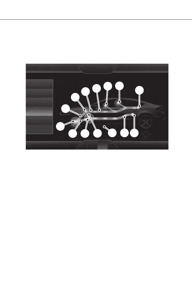
Save All
Touching this button stores your Default
Value Charge preferences
Note: Make sure you save your settings
before returning to the previous screen. If
you do not touch Save, your settings are not
stored in the system.
Power
A
H
DG
EF
BC
I
K
M L J
E161967
N
Motor-to-wheel flow shows the direction of power flow between the wheels
and the electric motor.
A
Electric Motor represents the hybrid electric motor. The higher the motor
power is, the larger the circle around this node. Any time the vehicle is ready to
be driven, the motor node illuminates.
B
Battery-to-motor flow1 shows the direction of power flow between the
high-voltage battery and the electric motor. Flow toward the motor indicates
the battery is providing power to accelerate the vehicle (discharging the battery).
Flow toward the battery indicates the electric motor is providing power to the
battery (charging the battery).
C
Plug (Energi only) appears when you plug your vehicle into the wall. When
charging the high voltage battery from the wall, you can see flow from the plug
to the battery on the screen.
D
Other2 includes all power usage from the low voltage accessories such as the
climate control fan, headlights and heated seats. The higher the power usage
is from these accessories, the larger the circle around the node. This node
illuminates anytime the vehicle is on since there is always some low level power
in use.
E
398
MyFord Touch™ (If Equipped)

Climate2,3 includes the power usage from the high-voltage climate control
components such as the electric A/C compressor and the electric heater (Energi
only). The higher the power usage is from these components, the larger the
circle around this node.
F
High voltage battery power represents your high-voltage battery. A circle
illuminates around the node when the high-voltage battery is receiving power
from regenerative braking, engine charging or external charging (when you plug
it in). The higher the power going into the high-voltage battery, the larger the
circle around this node.
G
Fuel represents the fuel tank in the vehicle.H
Fuel-to-engine flow shows flow from the fuel tank to the engine when the
engine is on and using fuel (there are some cases where the engine is on, but
not using any fuel). When the engine is on, but not using fuel, the engine node
is active, but the fuel flow path is off. An example of this is when your foot is
off the accelerator pedal and the vehicle is traveling at a high speed.
I
Engine On due to provides you with the reason(s) the gasoline engine is on.
When the gasoline engine is off, this display does not appear. Engine On due
to reasons displayed by the system are in a chart following this list.
J
Motor-to-engine flow shows the direction of power flow between the engine
and the electric motor. The direction indicates if the engine is providing power
to the high-voltage electrical system, or if the high-voltage electrical system is
providing power to control or start the engine.
K
Engine power represents the gasoline engine. It illuminates only when the
gasoline engine is on. The higher the engine power is, the larger the circle around
this node.
L
Engine-to-wheels flow shows the direction of the power flow between the
engine and the wheels.
M
Drive power represents the power going to the wheels. The higher the wheel
power is, the larger the circle around this node. When the engine is off, drive
power is shown in blue. When the engine is on, drive power is shown in grey.
N
1The battery-to-motor flow includes
battery power the vehicle is using for
acceleration. It does not include energy the
vehicle is using for accessories (such as air
conditioning, headlights and radio). This
screen displays accessories and climate
usage separately.
2Accessories indicates electrical power
demands from your vehicle’s accessory
systems. Accessories use power but do not
contribute to making the vehicle move. The
power flow displays power usage from the
climate control system and other
accessories separately.
3The climate control system may
determine A/C is necessary even when you
turn it off. In this case, you may see some
climate power when the A/C is off.
399
MyFord Touch™ (If Equipped)

Engine On due to
The engine is on to warm-up. The vehicle
returns to electric mode when the engine
is warm. This reason may reappear during
a drive or after shutting the vehicle down
for a short period. This is normal operation.
Engine Cold (Hybrid only)
The engine is on because of the heater
setting. Reduce or turn off the heater
setting to return to electric mode.
Heater Setting
The engine is on because the vehicle speed
exceeds the level for electric mode opera-
tion. Reduce the speed to return to electric
mode.
High Speed
The engine is on because the speed control
is on or you are pressing the accelerator
pedal. Reduce pressure on the accelerator
pedal or turn the speed control off to return
to full electric mode.
Acceleration
The engine is on because the vehicle is in
neutral gear. Shift out of neutral gear to
return to electric mode.
Neutral Gear
The engine is on because the vehicle is in
low gear. Shift out of low gear to return to
electric mode.
Low Gear
The engine is on to charge the high-voltage
battery. The vehicle returns to electric mode
once the battery is charged.
Battery Charging
The engine is on to provide increased
powertrain braking when you turn on the
grade assist feature. Turn off the grade
assist feature to return to electric mode.
Grade Assist
400
MyFord Touch™ (If Equipped)

Engine On due to
The engine is on to maintain engine oil
quality. The vehicle returns to electric mode
when engine oil maintenance is complete.
See Engine Oil Check (page 237).
Oil Maintenance (Energi Only)
The engine is on due to high or low high-
voltage battery temperature. This is a
normal operating condition. The vehicle
returns to electric mode automatically
when possible.
Batt Temperature (Energi Only)
The engine is on to optimize vehicle opera-
tion. The vehicle returns to electric mode
when possible.
Normal Operation
Status
This indicates which mode is active within
the vehicle system.
Hybrid Drive
The electric motor and gasoline engine are
powering vehicle.
Charging HV Battery
The hybrid system is storing power in the
high-voltage battery.
Idle
The vehicle is either at rest, or sharing very
little power between the electric system
parts.
Idle with Charging
The high-voltage battery is receiving power
in order to recharge.
Electric Drive
The vehicle is driving in electric mode (the
power is coming from the electric motor).
The gasoline engine is off in this mode.
Charge Complete (Energi only)
The high-voltage battery charging from
the wall is complete.
401
MyFord Touch™ (If Equipped)
INFORMATION
A
B
C
D
E
E161889
SYNC ServicesA
SIRIUS Travel LinkB
AlertsC
CalendarD
SYNC ApplicationsE
Under the Information menu, you can
access features such as:
• SYNC Services
• SIRIUS Travel Link
• Alerts
• Calendar
• SYNC Applications
E142608
If your vehicle is equipped with
Navigation, press the
Information button to access
these features. If your vehicle is not
equipped with Navigation, press the corner
of the touchscreen with the green tab.
SYNC Services (If Equipped, U.S.
Only)
Note: SYNC Services requires activation
before use. Visit www.SYNCMyRide.com to
register and check your eligibility for
complimentary services. Standard phone
and message rates may apply. Subscription
may be required. You must also have the
active SYNC Services Bluetooth-enabled
cellular phone paired and connected to the
system in order to connect to, and use,
SYNC Services. See Phone (page 385).
402
MyFord Touch™ (If Equipped)

Note: This feature does not function
properly if you have enabled caller ID
blocking on your cellular phone. Make sure
your cellular phone is not blocking caller ID
before using SYNC Services.
Note: The driver is ultimately responsible
for the safe operation of the vehicle, and
therefore, must evaluate whether it is safe
to follow the suggested directions. Any
navigation features provided are only an aid.
Make your driving decisions based on your
observations of local conditions and existing
traffic regulations. Do not follow the route
suggestions if doing so would result in an
unsafe or illegal maneuver, if you would be
placed in an unsafe situation, or if you would
be directed into an area that you consider
unsafe. Maps used by this system may be
inaccurate because of errors, changes in
roads, traffic conditions or driving
conditions.
Note: When you connect, the service uses
GPS technology and advanced vehicle
sensors to collect your vehicle's current
location, travel direction and speed to help
provide you with the directions, traffic
reports, or business searches you request.
Further, to provide the services you request,
for continuous improvement, the service
may collect and record call details and voice
communications. For more information, see
SYNC Services Terms and Conditions at
www.SYNCMyRide.com. If you do not want
Ford or its service providers to collect your
vehicle travel information or other
information identified in the Terms and
Conditions, do not subscribe or use the
service.
SYNC Services uses advanced vehicle
sensors, integrated GPS technology and
comprehensive map and traffic data, to
give you personalized traffic reports,
precise turn-by-turn directions, business
search, news, sports, weather and more.
For a complete list of services, or to learn
more, please visit www.SYNCMyRide.com.
Connecting to SYNC Services Using
Voice Commands
E142599
1. Press the voice button.
2. When prompted, say "Services". This
initiates an outgoing call to SYNC
Services using your paired and
connected Bluetooth-enabled cellular
phone.
3. Once you connect to the service, follow
the voice prompts to request the
desired service, such as "Traffic" or
"Directions". You can also say, "What
are my choices?" to receive a list of
available services from which to
choose.
4. Say, "Services" to return to the Services
main menu or for help, say, "Help".
Connecting to SYNC Services Using
the Touchscreen
E142608
If your vehicle is equipped with
Navigation, press the
Information button.
If your vehicle is not equipped with
Navigation, press the green tab on your
touchscreen.
1. Select Connect to Services to initiate
an outgoing call to SYNC Services
using your phone.
2. Once connected, follow the voice
prompts to request your desired
Service, such as "Traffic" or
"Directions". You can also say, "What
are my choices?" to receive a list of
available services from which to
choose.
3. Say, "Services" to return to the Services
main menu or for help, say, "Help".
403
MyFord Touch™ (If Equipped)

Receiving Turn-by-Turn Directions
1. When connected to SYNC Services,
say "Directions" or "Business search".
To find the closest business or type of
business to your current location, just
say "Business search" and then
"Search near me". If you need further
assistance in finding a location you can
say "Operator" at any time within a
Directions or Business search to speak
with a live operator. The system may
prompt you to speak with an operator
when it has difficulty matching your
voice request. The live operator can
assist you by searching for businesses
by name or by category, residential
addresses by street address or by
name or specific street intersections.
Operator Assist is a feature of your
SYNC Services subscription. For more
information on Operator Assist, visit
www.SYNCMyRide.com/support.
2. Follow the voice prompts to select your
Destination. After the route download
is finished, the phone call automatically
ends.
If your vehicle is not equipped with
Navigation:
• Turn-by-turn directions appear in the
information display, in the status bar
of your touchscreen system and on the
SYNC Services screen. You also receive
driving instructions from audible
prompts.
• When on an active route, you can
select Route Summary or Route
Status using the touchscreen controls
or voice commands to view the Route
Summary Turn List or the Route
Status ETA. You can also turn voice
guidance on or off, cancel the route or
update the route.
If you miss a turn, SYNC automatically asks
if you want the route updated. Just say,
"Yes" when prompted and the system
delivers a new route to your vehicle.
If your vehicle is equipped with Navigation,
SYNC Services downloads your requested
destination to the navigation system. The
navigation system then calculates the
route and provides driving instructions.
See Navigation (page 414).
Disconnecting from SYNC Services
1. Press and hold the hang-up phone
button on the steering wheel.
2. Say "Good-bye" from the SYNC
Services main menu.
404
MyFord Touch™ (If Equipped)
SYNC Services quick tips
You can personalize your Services feature to provide
quicker access to your most used or favorite information.
You can save address points, such as work or home. You
can also save favorite information like sports teams, such
as Detroit Lions, or a news category. You can learn more
about personalization by logging onto
www.SYNCMyRide.com.
Personalizing
Press the voice button at any time (while connected to
SYNC TDI Services) to interrupt a voice prompt or an audio
clip (such as a sports report) and say your voice command.
Push to interrupt
Your subscription is associated with your Bluetooth-
enabled cellular phone number, not your VIN (Vehicle
Identification Number). You can pair and connect your
phone to any vehicle equipped with Traffic, Directions and
Information and continue enjoying your personalized
services.
Portable
SYNC Services Voice Commands
E142599
When a route has been
downloaded (non-navigation
systems), press the voice button
on the steering wheel controls. When
prompted, say any of the following
commands:
"SERVICES"
"Cancel route"
"Navigation voice off"
"Navigation voice on"
"Next turn"
"Route status"
"Route summary"
"SERVICES"
"Services"
"Update route"
"Help"
SIRIUS Travel Link (If Equipped)
WARNING
Driving while distracted can result in
loss of vehicle control, crash and
injury. We strongly recommend that
you use extreme caution when using any
device that may take your focus off the
road. Your primary responsibility is the safe
operation of your vehicle. We recommend
against the use of any handheld device
while driving and encourage the use of
voice-operated systems when possible.
Make sure you are aware of all applicable
local laws that may affect the use of
electronic devices while driving.
405
MyFord Touch™ (If Equipped)
Note: In order to use SIRIUS Travel Link,
your vehicle must be equipped with
navigation and your navigation SD card
must be in the SD card slot.
Note: A paid subscription is required to
access and use these features. Go to
www.siriusxm.com/travellink for more
information.
Note: Visit www.siriusxm.com/traffic# and
click on Coverage map and details for a
complete listing of all traffic areas covered
by SIRIUS Travel Link.
Note: Neither SIRIUS nor Ford is responsible
for any errors or inaccuracies in the SIRIUS
Travel Link services or its use in vehicles.
When you subscribe to SIRIUS Travel Link,
it can help you locate the best gas prices,
find movie listings, get current traffic alerts,
view the current weather map, get
accurate ski conditions and see scores to
current sports games.
E142608
If your vehicle is equipped with
Navigation, touch the i
(Information) button to access
these features. If your vehicle is not
equipped with Navigation, touch the corner
of the touchscreen with the green tab.
Traffic On Route and Traffic Nearby
Touch these buttons to identify traffic
incidents on your route, nearby your
vehicle’s current location or near any of
your favorite places, if programmed.
Fuel Prices
Touch this button to view fuel prices at
stations close to your vehicle’s location or
on an active navigation route.
Movie Listings
Touch this button to view nearby movie
theaters and their show times, if available.
Weather
Touch this button to view the nearby
weather, current weather, or the five day
forecast for the chosen area. Select Map
to see the weather map, which can show
storms, radar information, charts and
winds. Select Area to select from a listing
of weather locations.
Sports Info
Touch this button to view scores and
schedules from a variety of sports. You can
also save up to 10 favorite teams for easier
access. The score automatically refreshes
when a game is in progress.
Ski Conditions
Touch this button to view ski conditions
for a specific area.
SIRIUS Travel Link Voice Commands
E142599
Press the voice button on the
steering wheel controls. When
prompted, say any of the
following commands:
"SIRIUS TRAVEL LINK"
"5-day weather forecast"
"Fuel prices"
"Movie listings"
"Sports headlines"*
"Sports schedules"*
"Sports scores"*
"Traffic"
"Weather"
406
MyFord Touch™ (If Equipped)

"SIRIUS TRAVEL LINK"
"Weather map"
"Help"
* If you say "Sports headlines", "Sports
schedules" or "Sports scores", you can
then say any of the commands in the
following chart.
Sports-related commands
"Baseball"
"College basketball"
"College football"
"Golf"
"MLS"
"My teams"
"NBA"
"NFL"
"NHL"
"WNBA"
"Help"
Additional sports-related voice
commands
"Baseball headlines"
"Baseball schedule"
"Baseball scores"
"College basketball headlines"
"College basketball schedule"
"College basketball scores"
"College football headlines"
Additional sports-related voice
commands
"College football schedule"
"College football scores"
"Golf headlines"
"Golf leaderboard"
"Golf schedule"
"MLS headlines"
"MLS schedule"
"MLS scores"
"Motor sports headlines"
"Motor sports order"
"Motor sports schedule"
"My team headlines"
"My teams schedule"
"My teams scores"
"NBA headlines"
"NBA schedule"
"NBA scores"
"NFL headlines"
"NFL schedule"
"NFL scores"
"NHL headlines"
"NHL schedule"
"NHL scores"
"WNBA headlines"
407
MyFord Touch™ (If Equipped)
Additional sports-related voice
commands
"WNBA schedule"
"WNBA scores"
"Help"
Alerts
E142608
If your vehicle is equipped with
Navigation, touch the i
(Information) button to access
these features. If your vehicle is not
equipped with Navigation, touch the corner
of the touchscreen with the green tab.
Press Alerts, and then choose from any
of the following services:
•View the complete message.
•Delete the message.
•Delete All messages.
This screen displays any system messages
(such as an SD card fault).
Note: The system alerts you to any
messages by turning the information icon
yellow. After you read or delete the
messages, the icon returns to white.
Calendar
E142608
If your vehicle is equipped with
Navigation, touch the i
(Information) button to access
these features. If your vehicle is not
equipped with Navigation, touch the corner
of the touchscreen with the green tab.
Press Calendar. You can view the current
calendar by day, week or month.
911 Assist (If Equipped)
WARNINGS
Unless the 911 Assist setting is set on
before a crash, the system will not
dial for help, which could delay
response time, potentially increasing the
risk of serious injury or death after a crash.
Do not wait for 911 Assist to make an
emergency call if you can do it
yourself. Dial emergency services
immediately to avoid delayed response
time, which could increase the risk of
serious injury or death after a crash. If you
do not hear 911 Assist within five seconds
of the crash, the system or phone may be
damaged or non-functional.
Always place your phone in a secure
location in your vehicle so it does not
become a projectile or damaged in
a crash. Failure to do so may cause serious
injury to someone or damage the phone,
which could prevent 911 Assist from
working properly.
Note: The SYNC 911 Assist feature must be
set on prior to the incident.
Note: Before setting this feature on, make
sure that you read the 911 Assist Privacy
Notice later in this section for important
information.
Note: If any user turns 911 Assist on or off,
that setting applies for all paired phones. If
911 Assist is turned off, either a voice
message plays or a display message (or
icon) comes on (or both) when your vehicle
is started after a previously paired phone
connects.
Note: Every phone operates differently.
While SYNC 911 Assist works with most
cellular phones, some may have trouble
using this feature.
408
MyFord Touch™ (If Equipped)

If a crash deploys an airbag (excludes knee
airbags and rear inflatable safety belts [if
equipped]) or activates the fuel pump
shut-off, your SYNC-equipped vehicle may
be able to contact emergency services by
dialing 911 through a paired and connected
Bluetooth-enabled phone. You can learn
more about the 911 Assist feature, visit
www.SYNCMyRide.com,
www.SYNCMyRide.ca or
www.syncmaroute.ca.
See Supplementary Restraints System
(page 33). Important information
regarding airbag deployment is in this
chapter.
See Roadside Emergencies (page 218).
Important information regarding the fuel
pump shut-off is in this chapter.
Setting 911 Assist On
E142608
If your vehicle is equipped with
Navigation, touch the i
(Information) button to access
these features. If your vehicle is not
equipped with Navigation, touch the corner
of the touchscreen with the green tab.
Touch Apps > 911 Assist, then select On.
E142607
You can also access 911 Assist
by:
• Pressing the Settings icon > Settings
> Phone > 911 Assist, or
• Pressing the Settings icon > Help > 911
Assist.
To make sure that 911 Assist works
properly:
• SYNC must be powered and working
properly at the time of the incident and
throughout feature activation and use.
• The 911 Assist feature must be set on
prior to the incident.
• You must pair and connect a
Bluetooth-enabled and compatible
phone to SYNC.
• A connected Bluetooth-enabled phone
must have the ability to make and
maintain an outgoing call at the time
of the incident.
• A connected Bluetooth-enabled phone
must have adequate network coverage,
battery power and signal strength.
• The vehicle must have battery power
and be located in the U.S., Canada or
in a territory in which 911 is the
emergency number.
In the Event of a Crash
Not all crashes deploy an airbag or activate
the fuel pump shut-off (which would
trigger 911 Assist); however, SYNC tries to
contact emergency services if 911 Assist
triggers. If a connected phone sustains
damage or loses connection to SYNC,
SYNC searches for, and tries to connect
to, any available previously paired phone
and tries to make the call to 911.
Before making the call:
• SYNC provides a short window of time
(about 10 seconds) to cancel the call.
If you fail to cancel the call, SYNC
attempts to dial 911.
• SYNC says the following, or a similar
message: "SYNC will attempt to call
911, to cancel the call, press Cancel on
your screen or press and hold the
phone button on your steering wheel."
If you do not cancel the call, and SYNC
makes a successful call, a pre-recorded
message plays for the 911 operator, and
then the occupant(s) in your vehicle is able
to talk with the operator. Be prepared to
provide your name, phone number and
location immediately, because not all 911
systems are capable of receiving this
information electronically.
409
MyFord Touch™ (If Equipped)
911 Assist May Not Work If
• Your cellular phone or 911 Assist
hardware sustains damage in a crash.
• The vehicle's battery or the SYNC
system has no power.
• The phone(s) thrown from your vehicle
are the ones paired and connected to
the system.
911 Assist Privacy Notice
When you turn on 911 Assist, it may
disclose to emergency services that your
vehicle has been in a crash involving the
deployment of an airbag or activation of
the fuel pump shut-off. Certain versions or
updates to 911 Assist may also be capable
of electronically or verbally disclosing to
911 operators your vehicle location or other
details about your vehicle or crash to assist
911 operators to provide the most
appropriate emergency services. If you do
not want to disclose this information, do
not turn the feature on.
Vehicle Health Report (If Equipped)
WARNING
Always follow scheduled
maintenance instructions, regularly
inspect your vehicle, and seek repair
for any damage or problem you suspect.
Vehicle Health Report supplements, but
cannot replace, normal maintenance and
vehicle inspection. Vehicle Health Report
only monitors certain systems
electronically monitored by your vehicle
and will not monitor or report the status
of any other system, (such as brake lining
wear). Failure to perform scheduled
maintenance and regularly inspect your
vehicle may result in vehicle damage and
serious injury.
Note: This feature is only available in the
United States.
Note: Your Vehicle Health Report feature
requires activation prior to use. Visit
www.SYNCMyRide.com to register. There
is no fee or subscription associated with
Vehicle Health Report, but you must register
to use this feature.
Note: This feature may not function
properly if you have enabled caller ID
blocking on your cellular phone. Before
running a report, review the Vehicle Health
Report Privacy Notice.
Note: In order to allow a break-in period for
your vehicle, you may not be able to create
a Vehicle Health Report until your vehicle
odometer has reached 200 miles.
Note: Cellular phone and SMS charges may
apply when making a report.
Register for Vehicle Health Report and set
your report preferences at
www.SYNCMyRide.com. After registering,
you can request a Vehicle Health Report
(inside your vehicle). Return to your
account at www.SYNCMyRide.com to view
your report. You can also choose for SYNC
to remind you automatically to run reports
at specific mileage intervals. Cellular phone
airtime usage may apply when reporting.
The system allows you to check your
vehicle’s overall health in the form of a
diagnostic report card. The Vehicle Health
Report contains valuable information, such
as:
• Vehicle diagnostic information
• Scheduled maintenance
• Open recalls and Field Service Actions
• Items noted during vehicle inspections
by your authorized dealer that still need
servicing.
Making a Report
E142608
If you want to run a report by
using the touchscreen, touch
Apps > Vehicle Health Report.
410
MyFord Touch™ (If Equipped)
E142599
To run a report by voice
command, press the voice
button on the steering wheel
and, when prompted, say "Vehicle health
report".
Vehicle Health Report Privacy Notice
When you create a Vehicle Health Report,
Ford Motor Company may collect your
cellular phone number (to process your
report request) and diagnostic information
about your vehicle. Certain versions or
updates to Vehicle Health Report may also
collect more vehicle information. Ford may
use your vehicle information it collects for
any purpose. If you do not want to disclose
your cellular phone number or vehicle
information, do not run the feature or set
up your Vehicle Health Report profile at
www.SYNCMyRide.com. See
www.SYNCMyRide.com (Vehicle Health
Report Terms and Conditions, and Privacy
Statement) for more information.
CLIMATE
Press the lower right corner on the
touchscreen to access your climate control
features. Depending on your vehicle line
and option package, your climate screen
may look different from the screen shown
here.
E146187
Power: Touch to switch the system off and on. Outside air cannot enter your
vehicle when you turn off the system.
A
Passenger settings: Touch DUAL to switch passenger side temperature
controls on and off. Touch the + and - to adjust the temperature. Touch the
heated seat icon to control the heated seat.
B
Fan speed: Touch + or - to increase or decrease the volume of air circulated
in your vehicle.
C
411
MyFord Touch™ (If Equipped)

Recirculated air: Touch the button to switch between outside air and
recirculated air. When recirculated air is selected, the button illuminates and
the air currently in the passenger compartment recirculates. This may reduce
the time needed to cool the interior (when used with A/C) and may also reduce
unwanted odors from entering your vehicle. Recirculated air may turn off
automatically in all airflow modes except MAX A/C to reduce the possibility of
fogging.
D
MAX A/C: Touch to cool your vehicle with recirculated air. Touch again for
normal A/C operation. MAX A/C distributes air through instrument panel vents
and may help reduce odors from entering your vehicle. MAX A/C is more
economical and efficient than normal A/C mode.
E
A/C: Touch to turn air conditioning on or off. To improve air conditioning when
starting your vehicle, drive with the windows slightly open for two to three
minutes. Use A/C with recirculated air to improve cooling performance and
efficiency.
F
AUTO: Touch to turn on fully automatic operation. Select the desired
temperature using the temperature control. The system automatically adjusts
fan speed, air distribution, A/C operation, and outside or recirculated air, to heat
or cool the vehicle to maintain the selected temperature.
G
Rear defroster: Touch to turn the rear window defroster and heated mirrors
(if equipped).
H
Manual airflow distribution controls:Floor and Defrost: Distributes air
through the windshield defroster vents, demister vents, floor vents and rear
seat floor vents, and provides outside air to reduce window fogging. Panel:
Distributes air through the instrument panel vents. Panel and Floor: Distributes
air through the instrument panel vents, demister vents, floor vents and rear seat
floor vents. Floor: Distributes air through the demister vents, floor vents and
rear seat floor vents. Defrost: Distributes outside air through the windshield
air vents and automatically switches the air conditioning on. Touch to clear the
windshield of fog and thin ice. Touch again to return to the previous airflow
selection.
I
Driver settings: Depending on your vehicle and option package, you may have
the following features: Touch the + and - to adjust the temperature. Touch the
heated seat icon to control the heated seat. Touch MyTemp to select your
previously pre-set temperature setpoint. Touch and hold MyTemp store a new
pre-set for temperature setpoint.
J
Climate Control Voice Commands
E142599
Press the voice button on the
steering wheel controls. When
prompted, say any of the
following commands:
Climate Control Commands
"Climate automatic"
"Climate my temperature"
"Climate off"
412
MyFord Touch™ (If Equipped)

Climate Control Commands
"Climate on"
"Climate temperature <15.5-29.5>
degrees"
"Climate temperature <60-85> degrees"
"Help"
There are additional climate control
commands but in order to access them,
you have to say "Climate" first. When the
system is ready to listen, you may say any
of the following commands:
"CLIMATE"
"A/C off"
"A/C on"
"Automatic"
"Defrost off"
"Defrost on"
"Dual off"
"Fan decrease"
"Fan increase"
"Floor on"
"MAX A/C off"
"MAX A/C on"
"Maximum fan
"Minimum fan"
"My temp"
"Off"
"On"
"Panel floor on"
"CLIMATE"
"Panel on"
"Rear defrost on"
"Rear defrost off"
"Recirc off"
"Recirc on"
"Temperature"*
"Temperature <15.5-29.5> degrees"
"Temperature <60-85> degrees"
"Temperature decrease"
"Temperature high"
"Temperature increase"
"Temperature low"
"Windshield floor on"
"Windshield off"
"Windshield panel floor on"
"Help"
* If you say "Temperature", you can then
say any of the commands in the following
chart.
"TEMPERATURE"
"<15.5-29.5> degrees"
"<60-85> degrees"
"High"
"Low"
"Help"
413
MyFord Touch™ (If Equipped)

NAVIGATION
Note: The navigation SD card must be in
the SD card slot to operate the navigation
system. If you need a replacement SD card,
see an authorized dealer.
Note: The SD card slot is spring-loaded. To
remove the SD card, just push the card in
and release it. Do not attempt to pull the
card out to remove it; this could cause
damage.
Your navigation system is comprised of
two main features, destination mode and
map mode.
To set a destination, press the green corner
of your touchscreen, then the Dest button
when it appears. See Setting a
destination later in this chapter.
To view the navigation map and your
vehicle's current location, touch the green
bar in the upper right hand corner of the
touchscreen, or, press Dest, then Map. See
Map mode later in this chapter.
Setting a Destination
Press the green corner of your touchscreen,
then the Dest button when it appears.
Choose any of the following:
Destination
My Home
Favorites
Previous Destinations
Point of Interest
Emergency
Street Address
Intersection
Destination
City Center
Map
Edit Route Cancel Route
1. Enter the necessary information into
the highlighted text fields (in any
order). For address destination entry,
the Go! button appears once you enter
all the necessary information. Pressing
the Go! button makes the address
location appear on the map. If you
choose Previous Destination, the last
20 destinations you have selected
appear.
2. Select Set as Dest to make this your
destination. You can also choose to set
this as a waypoint (have the system
route to this point on the way to your
current destination) or save it as a
favorite. The system considers any
Avoid Areas selections in its route
calculation.
3. Choose from up to three different types
of routes, and then select Start Route.
• Fastest: Uses the fastest moving roads
possible.
• Shortest: Uses the shortest distance
possible.
• Eco Route: Uses the most fuel-efficient
route.
You can cancel the route or have the
system demo the route for you. Select
Route Prefs to set route preferences like
avoiding freeways, tollroads, ferries and
car trains as well as to use or not use
high-occupancy vehicle lanes.
(High-occupancy vehicle lanes are also
known as carpool or diamond lanes.
People who ride in buses, vanpools or
carpools use these lanes.)
414
MyFord Touch™ (If Equipped)

Note: If your vehicle is on a recognized road
and you do not press the Start Route
button, the system defaults to the Fastest
Route option and begins guidance.
During route guidance, you can press the
talking bubble icon that appears in the
upper right navigation corner (green bar)
if you want the system to repeat route
guidance information. When the system
repeats the last guidance instruction, it
updates the distance to the next guidance
instruction, since it detects when the
vehicle is moving.
Point of Interest (POI) Categories
Main categories
Food/Drink & Dining
Travel & Transportation
Financial
Emergency
Community
Health & Medicine
Automotive
Shopping
Main categories
Entertainment & Arts
Recreation & Sports
Government
Domestic Services
Subcategories
Restaurant
Golf
Parking
Home & Garden
Personal Care Services
Auto Dealership
Govt Office
Public Transit
Education
To expand these listings, press the + in
front of the listing.
The system also allows you to sort
alphabetically, by distance or by cityseekr
listings (if available).
415
MyFord Touch™ (If Equipped)
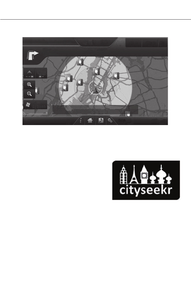
Range Rings and Charge Points (Energi Only)
E161378
Shaded rings appear on the map when you
are driving in EV Now mode. The inner ring
with no shading indicates a safe range you
can travel using plug-in power only. The
lightly shaded outer band reflects areas
you may or may not be able to reach while
in EV Now mode. If your destination is
within this band, your vehicle may operate
in Auto EV mode, running the engine as
needed. The darker shaded area, beyond
the rings, is not likely reachable using only
the vehicle's available plug-in energy.
The rings represent approximate ranges.
Actual route distances, road grades,
vehicle speed, accessory usage and other
conditions affect how far your vehicle can
travel in EV Now mode before recharging.
You can turn off the rings in the Settings
menu. Press the Settings icon >
Navigation > Map Preferences.
You can turn the charge point POI on and
off. Touch the map, use the buttons at the
bottom of the screen, and then select the
POI icon button. The icons only appear at
a map scale of 5 miles (8 kilometers) and
lower.
cityseekr
Note: cityseekr point of interest (POI)
information is limited to approximately 154
cities (132 in the United States, 13 in Canada
and 9 in Mexico).
E142634
cityseekr, when available, is a service that
provides more information about certain
points of interest such as restaurants,
hotels and attractions.
When you have selected a point of interest,
the location and information appear, such
as address and phone number. If cityseekr
lists the point of interest, more information
is available, such as a brief description,
check-in and checkout times or restaurant
hours.
416
MyFord Touch™ (If Equipped)
Press More Information for a longer
review, a list of services and facilities, the
average room or meal price as well as the
website. This screen displays the point of
interest icon such as:
E143884
Hotel
E142636
Coffeehouse
E142637
Food & Drink
E142638
Nightlife
E142639
Attraction
E142640
This icon appears when your
selection exists in multiple
categories within the system.
When you are viewing more information
for hotels, cityseekr also tells you if the
hotel has certain services and facilities
using icons, such as:
• Restaurant
• Business center
• Handicap facilities
• Laundry
• Refrigerator
• 24 hour room service
• Fitness center
• Internet access
• Pool
• Wi-fi.
For restaurants, cityseekr can provide
information such as star rating, average
cost, review, handicap access, hours of
operation, and website address.
For hotels, cityseekr can provide
information such as star rating, price
category, review, check-in and checkout
times, hotel service icons and website
address.
Setting Your Navigation
Preferences
Select settings for the system to take into
account when planning your route.
E142607
Press the Settings icon >
Settings > Navigation.
Map Preferences
Breadcrumbs
Display your vehicle’s previously traveled
route with white dots. Turn this feature ON
or OFF.
Turn List Format
Have the system display your turn list Top
to Bottom or Bottom to Top.
Parking POI Notification
Set the automatic parking point of interest
notification. Turn this feature ON or OFF.
When parking point of interest notification
is on, the icons display on the map when
you get close to your destination. This may
not be very useful in dense areas, and may
clutter the map when other points of
interest display.
417
MyFord Touch™ (If Equipped)

Route Preferences
Preferred Route
Choose to have the system display the
Shortest, Fastest or most Ecological route
first.
Always Use Preferred Route
Bypass route selection in destination
programming. The system only calculates
one route based on preferred route setting.
Eco Time Penalty
Select a low, medium or high cost for the
calculated Eco Route. The higher the
setting, the longer the time allotment is for
the route.
Avoid
These features allow you to choose to
have the system avoid freeways, toll roads,
ferries and car trains when planning your
route. Turn these features ON or OFF.
Use HOV Lanes
Have the system use high-occupancy
vehicle lanes, if available, when planning
your route.
Navigation Preferences
Guidance Prompts
Have the system use Voice & Tones or
Tone Only on your programmed route.
Auto - Fill State/Province
Have the system automatically fill in the
state and province based on the
information already entered into the
system. Turn this feature ON or OFF.
Traffic Preferences
Avoid Traffic Problems
Choose how you want the system to
handle traffic problems along your route.
•Automatic: Have the system reroute
you to avoid traffic incidents that
develop and impact the current route.
The system does not provide a traffic
alert notification.
•Manual: Have the system always
provide a traffic alert notification for
traffic incidents along the planned
route. You have a choice to accept or
ignore the notification before making
the route deviation.
Traffic Alert Notification
Have the system display traffic alert
notifications.
Other traffic alert features allows you to
turn on certain, or all, traffic icons on the
map such as road work, incident, accidents
and closed roads. Scroll down to view all
the different types of alerts. Turn these
features ON or OFF.
Avoid Areas
Choose areas which you want the system
to avoid when calculating a route for you.
Press Add to program an entry. Once you
make a selection, the system tries to avoid
the area(s) if possible for all routes. To
delete a selection, choose the listing on
the screen. When the screen changes to
Avoid Areas Edit, you can press Delete
at the bottom right of the screen.
Map Mode
Press the green bar in the upper right area
of the touchscreen to view map mode. Map
mode shows advanced viewing comprised
of both 2D city maps as well as 3D
landmarks (when available).
418
MyFord Touch™ (If Equipped)
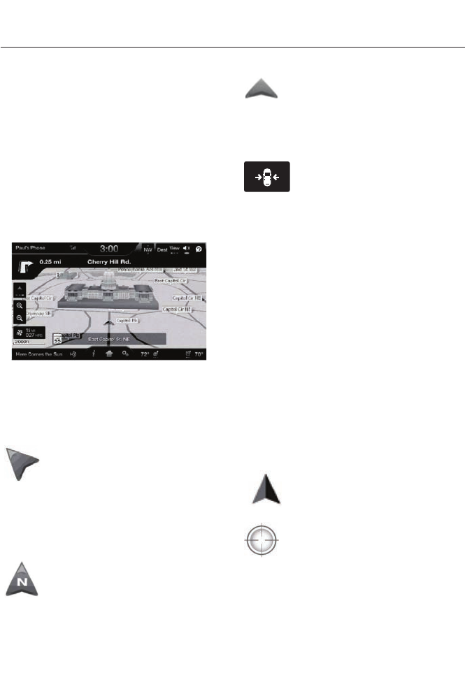
2D city maps show detailed outlines of
buildings, visible land use and land
elements and detailed railway
infrastructure for the most essential cities
around the globe. These maps also contain
features, such as town blocks, building
footprints, and railways.
3D landmarks appear as clear, visible
objects that are typically recognizable and
have a certain tourist value. The 3D
landmarks appear in 3D map mode only.
Coverage varies, and improves with
updated map releases.
E142641
Change the appearance of the map display
by repeatedly pressing the arrow button in
the upper left corner of the screen. It
toggles between three different map
modes: Heading up, North up, and 3D.
E142642
Heading up (2D map) always
shows the direction of forward
travel to be upward on the screen.
This view is available for map
scales up to 2.5 miles (4 kilometers). The
system remembers this setting for larger
map scales, but shows the map in North
up only. If the scale returns below this level,
the system restores Heading up.
E142643
North up (2D map) always shows
the northern direction to be
upward on the screen.
E142644
3D map mode provides an
elevated perspective of the map.
This viewing angle can be adjusted
and the map can be rotated 180
degrees by touching the map twice, and
then dragging your finger along the shaded
bar with arrows at the bottom of the map.
E146188
Re-center the map by pressing
this icon whenever you scroll the
map away from your vehicle’s
current location.
Auto Zoom
Press the green bar to access map mode,
then select the + or - zoom button to bring
up the zoom level and Auto buttons on the
touchscreen. When you press Auto, Auto
Zoom turns on and Auto displays in the
bottom left corner of the screen in the map
scale. The map zoom level then
synchronizes with vehicle speed. The
slower your vehicle is traveling, the farther
in the map zooms in; the faster your vehicle
is traveling, the farther the map zooms out.
To turn the feature off, just press the + or
- button again.
In 3D mode, rotate the map view by
swiping your finger across the shaded bar
with the arrows.
Map Icons
E142646
Vehicle mark shows the current
location of your vehicle. It stays
in the center of the map display,
except when in scroll mode.
E142647
Scroll cursor allows you to scroll
the map; the fixed icon is in the
center of the screen. The map
position closest to the cursor is in
a window on the top center part of the
screen.
419
MyFord Touch™ (If Equipped)
E142648
Address book entry default
icon(s) indicates the location on
the map of an address book entry.
This is the default symbol shown
after the entry has been stored to the
Address Book by any method other than
the map. You can select from any of the
22 icons available. You can use each icon
more than once.
E142649
Home indicates the location on
the map currently stored as the
home position. You can only save
one address from the Address
Book as your Home entry. You cannot
change this icon.
E142650
POI (Point Of Interest) icons
indicate locations of any point of
interest categories you choose to
display on the map. You can
choose to display three point of interest
categories on the map at one time.
E142651
Starting point indicates the
starting point of a planned route.
E142652
Waypoint indicates the location
of a waypoint on the map. The
number inside the circle is different
for each waypoint and represents
the position of the waypoint in the route
list.
E142653
Destination symbol indicates the
ending point of a planned route.
E142654
Next maneuver point indicates
the location of the next turn on the
planned route.
E142655
No GPS symbol indicates that
insufficient GPS satellite signals
are available for accurate map
positioning. This icon may display
under normal operation in an area with
poor GPS access.
Quick-touch Buttons
When in map mode, touch anywhere on
the map display to access the following
options:
Set as Dest
Touch this button to select a scrolled
location on the map as your destination.
You may scroll the map by pressing your
index finger on the map display. When you
reach the desired location, simply let go
and then touch Set as Dest.
Set as Waypoint
Touch this button to set the current
location as a waypoint.
Save to Favorites
Touch this button to save the current
location to your favorites.
POI Icons
Touch this button to select icons to display
on the map. You can select up to three
icons to display on the map at the same
time. Turn these ON or OFF.
Cancel Route
Touch this button to cancel the active
route.
View/Edit Route
Access these features when a route is
active:
• View Route
• Edit Destination/Waypoints
• Edit Turn List
• Detour
• Edit Route Preferences
• Edit Traffic Preferences
• Cancel Route.
420
MyFord Touch™ (If Equipped)
Navteq is the digital map provider for the
navigation application. If you find map data
errors, you may report them directly to
Navteq by going to
http://mapreporter.navteq.com. Navteq
evaluates all reported map errors and
responds with the result of their
investigation by e-mail.
Navigation Map Updates
Annual navigation map updates are
available for purchase through your
dealership, by calling 1-800-NAVMAPS (in
Mexico, call 01-800-557-5539) or going
to www.navigation.com/ford. You need to
specify the make and model of your vehicle
to determine if there is an update available.
Navigation Voice Commands
E142599
When in navigation mode, press
the voice button on the steering
wheel controls. After the tone,
say any of the following commands:
Navigation system voice commands
"Cancel next waypoint" 1
"Cancel route"1
"Destination"2
"Destination <nametag>"
"Destination <POI category>"
"Destination favorites"
"Destination home"
"Destination intersection"
"Destination nearest <POI category>"
"Destination nearest POI"
"Destination play nametags"
Navigation system voice commands
"Destination POI"
"Destination POI category"
"Destination previous destination"
"Destination street address"
"Detour"1
"Navigation"3
"Navigation voice volume decrease"
"Navigation voice volume increase"
"Repeat instruction"1
"Show 3D"
"Show heading up"
"Show map"
"Show north up"
"Show route"1
"Show turn list"1
"Voice guidance off"
"Voice guidance on"
"Where am I?"
"Zoom in"
421
MyFord Touch™ (If Equipped)

Navigation system voice commands
"Zoom out"
"Help"
1 These commands are only available when
a navigation route is active.
2 If you say "Destination", you can then say
any command in the following
"Destination" chart.
3 If you say "Navigation", you can then say
any command in the following
"Navigation" chart.
"DESTINATION"
"<nametag>"
"<POI category>"
"Favorites"
"Home"
"Intersection"
"Nearest <POI category>"
"Nearest POI"
"Play nametags"
"POI category"
"Previous destination"
"Street address"
"Help"
"NAVIGATION"
"Destination"*
"Zoom city"
"Zoom country"
"Zoom minimum"
"NAVIGATION"
"Zoom maximum"
"Zoom province"
"Zoom state"
"Zoom street"
"Zoom to <distance>"
"Help"
* If you say "Destination", you can then say
any command in the "Destination" chart.
One-shot Destination Street Address
When you say either "Navigation
destination street address" or "Destination
street address", the system asks you to say
the full address. The system displays an
example on-screen. You can then speak
the address naturally, such as "One two
three four Main Street, Anytown".
422
MyFord Touch™ (If Equipped)

END USER LICENSE
AGREEMENT
SYNC® End User License
Agreement (EULA)
• You have acquired a device ("DEVICE")
that includes software licensed by Ford
Motor Company and its affiliates
("FORD MOTOR COMPANY") from an
affiliate of Microsoft Corporation
("MS") . Those installed software
products of MS origin, as well as
associated media, printed materials,
and "online" or electronic
documentation ("MS SOFTWARE")
are protected by international
intellectual property laws and treaties.
The MS SOFTWARE is licensed, not
sold. All rights reserved.
• The MS SOFTWARE may interface with
and/or communicate with, or may be
later upgraded to interface with and/or
communicate with additional software
and/or systems provided by FORD
MOTOR COMPANY. The additional
software and systems of FORD
MOTOR COMPANY origin, as well as
associated media, printed materials,
and "online" or electronic
documentation ("FORD SOFTWARE")
are protected by international
intellectual property laws and treaties.
The FORD SOFTWARE is licensed, not
sold. All rights reserved.
• The MS SOFTWARE and/or FORD
SOFTWARE may interface with and/or
communicate with, or may be later
upgraded to interface with and/or
communicate with additional software
and/or systems provided by third party
software and service suppliers. The
additional software and services of
third party origin, as well as associated
media, printed materials, and "online"
or electronic documentation ("THIRD
PARTY SOFTWARE") are protected by
international intellectual property laws
and treaties. The THIRD PARTY
SOFTWARE is licensed, not sold. All
rights reserved.
• The MS SOFTWARE, FORD
SOFTWARE and THIRD PARTY
SOFTWARE hereinafter collectively
and individually will be referred to as
"SOFTWARE".
IF YOU DO NOT AGREE TO THIS END
USER LICENSE AGREEMENT ("EULA")
DO NOT USE THE DEVICE OR COPY
THE SOFTWARE. ANY USE OF THE
SOFTWARE, INCLUDING BUT NOT
LIMITED TO USE ON THE DEVICE, WILL
CONSTITUTE YOUR AGREEMENT TO
THIS EULA (OR RATIFICATION OF ANY
PREVIOUS CONSENT).
GRANT OF SOFTWARE LICENSE: This
EULA grants you the following license:
• You may use the SOFTWARE as
installed on the DEVICE and as
otherwise interfacing with systems
and/or services provide by or through
FORD MOTOR COMPANY or its third
party software and service providers.
423
Appendices

Description of Other Rights and
Limitations
•Speech Recognition: If the
SOFTWARE includes speech
recognition component(s), you should
understand that speech recognition is
an inherently statistical process and
that recognition errors are inherent in
the process. Neither FORD MOTOR
COMPANY nor its suppliers shall be
liable for any damages arising out of
errors in the speech recognition
process.
•Limitations on Reverse Engineering,
Decompilation and Disassembly:
You may not reverse engineer,
decompile, or disassemble nor permit
others to reverse engineer, decompile
or disassemble the SOFTWARE, except
and only to the extent that such activity
is expressly permitted by applicable
law notwithstanding this limitation.
•Limitations on Distributing,
Copying, Modifying and Creating
Derivative Works: You may not
distribute, copy, make modifications
to or create derivative works based on
the SOFTWARE, except and only to the
extent that such activity is expressly
permitted by applicable law
notwithstanding this limitation.
•Single EULA: The end user
documentation for the DEVICE and
related systems and services may
contain multiple EULAs, such as
multiple translations and/or multiple
media versions (e.g., in the user
documentation and in the software).
Even if you receive multiple EULAs, you
are licensed to use only one (1) copy of
the SOFTWARE.
•SOFTWARE Transfer: You may
permanently transfer your rights under
this EULA only as part of a sale or
transfer of the DEVICE, provided you
retain no copies, you transfer all of the
SOFTWARE (including all component
parts, the media and printed materials,
any upgrades, and, if applicable, the
Certificate(s) of Authenticity), and the
recipient agrees to the terms of this
EULA. If the SOFTWARE is an upgrade,
any transfer must include all prior
versions of the SOFTWARE.
•Termination: Without prejudice to any
other rights, FORD MOTOR COMPANY
or MS may terminate this EULA if you
fail to comply with the terms and
conditions of this EULA.
•Security Updates/Digital Rights
Management: Content owners use
the WMDRM technology included in
your DEVICE to protect their
intellectual property, included
copyrighted content. Portions of the
SOFTWARE on your DEVICE use
WMDRM software to access
WMDRM-protected content. If the
WMDRM software fails to protect the
content, content owners may ask
Microsoft to revoke the SOFTWARE's
ability to use WMDRM to play or copy
protected content. This action does
not affect unprotected content. When
your DEVICE downloads licenses for
protected content, you agree that
Microsoft may include a revocation list
with the licenses. Content owners may
require you to upgrade the SOFTWARE
on your DEVICE to access their content.
If you decline an upgrade, you will not
be able to access content that requires
the upgrade.
424
Appendices

•Consent to Use of Data: You agree
that MS, Microsoft Corporation, FORD
MOTOR COMPANY, third party
software and systems suppliers, their
affiliates and/or their designated agent
may collect and use technical
information gathered in any manner as
part of product support services related
to the SOFTWARE or related services.
MS, Microsoft Corporation, FORD
MOTOR COMPANY, third party
software and services suppliers, their
affiliates and/or their designated agent
may use this information solely to
improve their products or to provide
customized services or technologies to
you. MS, Microsoft Corporation, FORD
MOTOR COMPANY, third party
software and systems suppliers, their
affiliates and/or their designated agent
may disclose this information to others,
but not in a form that personally
identifies you.
•Internet-Based Services
Components: The SOFTWARE may
contain components that enable and
facilitate the use of certain
Internet-based services. You
acknowledge and agree that MS,
Microsoft Corporation, FORD MOTOR
COMPANY, third party software and
service suppliers, their affiliates and/or
their designated agent may
automatically check the version of the
SOFTWARE and/or its components
that you are utilizing and may provide
upgrades or supplements to the
SOFTWARE that may be automatically
downloaded to your DEVICE.
•Additional Software/Services: The
SOFTWARE may permit FORD MOTOR
COMPANY, third party software and
service suppliers, MS, Microsoft
Corporation, their affiliates and/or their
designated agent to provide or make
available to you SOFTWARE updates,
supplements, add-on components, or
Internet-based services components
of the SOFTWARE after the date you
obtain your initial copy of the
SOFTWARE ("Supplemental
Components").
If FORD MOTOR COMPANY or third party
software and services suppliers provide or
make available to you Supplemental
Components and no other EULA terms are
provided along with the Supplemental
Components, then the terms of this EULA
shall apply.
If MS, Microsoft Corporation, their affiliates
and/or their designated agent make
available Supplemental Components, and
no other EULA terms are provided, then
the terms of this EULA shall apply, except
that the MS, Microsoft Corporation or
affiliate entity providing the Supplemental
Component(s) shall be the licensor of the
Supplemental Component(s).
FORD MOTOR COMPANY, MS, Microsoft
Corporation, their affiliates and/or their
designated agent reserve the right to
discontinue without liability any
Internet-based services provided to you or
made available to you through the use of
the SOFTWARE.
425
Appendices

•Links to Third Party Sites: The MS
SOFTWARE may provide you with the
ability to link to third party sites through
the use of the SOFTWARE. The third
party sites are not under the control of
MS, Microsoft Corporation, their
affiliates and/or their designated
agent. Neither MS nor Microsoft
Corporation nor their affiliates nor their
designated agent are responsible for
(i) the contents of any third party sites,
any links contained in third party sites,
or any changes or updates to third
party sites, or (ii) webcasting or any
other form of transmission received
from any third party sites. If the
SOFTWARE provides links to third
party sites, those links are provided to
you only as a convenience, and the
inclusion of any link does not imply an
endorsement of the third party site by
MS, Microsoft Corporation, their
affiliates and/or their designated
agent.
•Obligation to Drive Responsibly:
You recognize your obligation to drive
responsibly and keep attention on the
road. You will read and abide with the
DEVICE operating instructions
particularly as they pertain to safety
and assumes any risk associated with
the use of the DEVICE.
UPGRADES AND RECOVERY MEDIA:
If the SOFTWARE is provided by FORD
MOTOR COMPANY separate from the
DEVICE on media such as a ROM chip, CD
ROM disk(s) or via web download or other
means, and is labeled "For Upgrade
Purposes Only" or "For Recovery Purposes
Only" you may install one (1) copy of such
SOFTWARE onto the DEVICE as a
replacement copy for the existing
SOFTWARE, and use it in accordance with
this EULA, including any additional EULA
terms accompanying the upgrade
SOFTWARE.
INTELLECTUAL PROPERTY RIGHTS:
All title and intellectual property rights in
and to the SOFTWARE (including but not
limited to any images, photographs,
animations, video, audio, music, text and
"applets" incorporated into the
SOFTWARE), the accompanying printed
materials, and any copies of the
SOFTWARE, are owned by MS, Microsoft
Corporation, FORD MOTOR COMPANY, or
their affiliates or suppliers. The
SOFTWARE is licensed, not sold. You may
not copy the printed materials
accompanying the SOFTWARE. All title
and intellectual property rights in and to
the content which may be accessed
through use of the SOFTWARE is the
property of the respective content owner
and may be protected by applicable
copyright or other intellectual property
laws and treaties. This EULA grants you no
rights to use such content. All rights not
specifically granted under this EULA are
reserved by MS, Microsoft Corporation,
FORD MOTOR COMPANY, third party
software and service providers, their
affiliates and suppliers. Use of any on-line
services which may be accessed through
the SOFTWARE may be governed by the
respective terms of use relating to such
services. If this SOFTWARE contains
documentation that is provided only in
electronic form, you may print one copy of
such electronic documentation.
EXPORT RESTRICTIONS: You
acknowledge that the SOFTWARE is
subject to U.S. and European Union export
jurisdiction. You agree to comply with all
applicable international and national laws
that apply to the SOFTWARE, including
the U.S. Export Administration Regulations,
as well as end-user, end-use and
destination restrictions issued by U.S. and
other governments. For additional
information, see
http://www.microsoft.com/exporting/.
426
Appendices

TRADEMARKS: This EULA does not grant
you any rights in connection with any
trademarks or service marks of FORD
MOTOR COMPANY, MS, Microsoft
Corporation, third party software or service
providers, their affiliates or suppliers.
PRODUCT SUPPORT: Product support
for the SOFTWARE is not provided by MS,
its parent corporation Microsoft
Corporation, or their affiliates or
subsidiaries. For product support, please
refer to FORD MOTOR COMPANY
instructions provided in the documentation
for the DEVICE. Should you have any
questions concerning this EULA, or if you
desire to contact FORD MOTOR
COMPANY for any other reason, please
refer to the address provided in the
documentation for the DEVICE.
No Liability for Certain Damages:
EXCEPT AS PROHIBITED BY LAW, FORD
MOTOR COMPANY, ANY THIRD PARTY
SOFTWARE OR SERVICES SUPPLIERS,
MS, MICROSOFT CORPORATION AND
THEIR AFFILIATES SHALL HAVE NO
LIABILITY FOR ANY INDIRECT, SPECIAL,
CONSEQUENTIAL OR INCIDENTAL
DAMAGES ARISING FROM OR IN
CONNECTION WITH THE USE OR
PERFORMANCE OF THE SOFTWARE. THIS
LIMITATION SHALL APPLY EVEN IF ANY
REMEDY FAILS OF ITS ESSENTIAL
PURPOSE. IN NO EVENT SHALL MS,
MICROSOFT CORPORATION AND/OR
THEIR AFFILIATES BE LIABLE FOR ANY
AMOUNT IN EXCESS OF U.S. TWO
HUNDRED FIFTY DOLLARS (U.S.
$250.00).
• THERE ARE NO WARRANTIES OTHER
THAN THOSE THAT MAY EXPRESSLY
BE PROVIDED FOR YOUR NEW
VEHICLE.
Adobe
Contains Adobe® [Flash® Player] or
[AIR®] technology by Adobe Systems
Incorporated. This [Licensee Product]
contains [Adobe® Flash® Player]
[Adobe® AIR®] software under license
from Adobe Systems Incorporated,
Copyright ©1995-2009 Adobe
Macromedia Software LLC. All rights
reserved. Adobe, Flash and AIR are
trademarks of Adobe Systems
Incorporated.
End User Notice
Microsoft® Windows® Mobile for
Automotive Important Safety
Information
This system Ford SYNC™ contains
software that is licensed to Manufacturer
FORD MOTOR COMPANY by an affiliate
of Microsoft Corporation pursuant to a
license agreement. Any removal,
reproduction, reverse engineering or other
unauthorized use of the software from this
system in violation of the license
agreement is strictly prohibited and may
subject you to legal action.
Read and follow instructions: Before
using your Windows Automotive- based
system, read and follow all instructions
and safety information provided in this end
user manual ("User's Guide"). Not
following precautions found in this User's
Guide can lead to an accident or other
serious consequences.
Keep User's Guide in vehicle: When kept
in the vehicle, the User's Guide will be a
ready reference for you and other users
unfamiliar with the Windows
Automotive-based system. Please make
certain that before using the system for
the first time, all persons have access to
the User's Guide and read its instructions
and safety information carefully.
427
Appendices

WARNING
Operating certain parts of this
system while driving can distract
your attention away from the road,
and possibly cause an accident or other
serious consequences. Do not change
system settings or enter data non-verbally
(using your hands) while driving. Stop the
vehicle in a safe and legal manner before
attempting these operations. This is
important since while setting up or
changing some functions you might be
required to distract your attention away
from the road and remove your hands from
the wheel.
General Operation
Voice Command Control: Functions
within the Windows Automotive-based
system may be accomplished using only
voice commands. Using voice commands
while driving allows you to operate the
system without removing your hands from
the wheel.
Prolonged Views of Screen: Do not
access any function requiring a prolonged
view of the screen while you are driving.
Pull over in a safe and legal manner before
attempting to access a function of the
system requiring prolonged attention. Even
occasional short scans to the screen may
be hazardous if your attention has been
diverted away from your driving task at a
critical time.
Volume Setting: Do not raise the volume
excessively. Keep the volume at a level
where you can still hear outside traffic and
emergency signals while driving. Driving
while unable to hear these sounds could
cause an accident.
Use of Speech Recognition Functions:
Speech recognition software is inherently
a statistical process which is subject to
errors. It is your responsibility to monitor
any speech recognition functions included
in the system and address any errors.
Navigation Features: Any navigation
features included in the system are
intended to provide turn by turn
instructions to get you to a desired
destination. Please make certain all
persons using this system carefully read
and follow instructions and safety
information fully.
Distraction Hazard: Any navigation
features may require manual (non-verbal)
setup. Attempting to perform such set-up
or insert data while driving can seriously
distract your attention and could cause an
accident or other serious consequences.
Stop the vehicle in a safe and legal manner
before attempting these operations.
Let Your Judgment Prevail: Any
navigation features are provided only as
an aid. Make your driving decisions based
on your observations of local conditions
and existing traffic regulations. Any such
feature is not a substitute for your personal
judgment. Any route suggestions made by
this system should never replace any local
traffic regulations or your personal
judgment or knowledge of safe driving
practices.
Route Safety: Do not follow the route
suggestions if doing so would result in an
unsafe or illegal maneuver, if you would be
placed in an unsafe situation, or if you
would be directed into an area that you
consider unsafe. The driver is ultimately
responsible for the safe operation of the
vehicle and therefore, must evaluate
whether it is safe to follow the suggested
directions.
428
Appendices

Potential Map Inaccuracy: Maps used
by this system may be inaccurate because
of changes in roads, traffic controls or
driving conditions. Always use good
judgment and common sense when
following the suggested routes.
Emergency Services: Do not rely on any
navigation features included in the system
to route you to emergency services. Ask
local authorities or an emergency services
operator for these locations. Not all
emergency services such as police, fire
stations, hospitals and clinics are likely to
be contained in the map database for such
navigation features.
TeleNav Software End User License
Agreement
Please read these terms and conditions
carefully before you use the TeleNav
Software. Your use of the TeleNav
Software indicates that you accept these
terms and conditions. If you do not accept
these terms and conditions, do not break
the seal of the package, launch, or
otherwise use the TeleNav Software.
TeleNav may revise this Agreement and
the privacy policy at any time, with or
without notice to you. You agree to visit
http://www.telenav.com from time to time
to review the then current version of this
Agreement and of the privacy policy.
1. Safe and Lawful Use
You acknowledge that devoting attention
to the TeleNav Software may pose a risk
of injury or death to you and others in
situations that otherwise require your
undivided attention, and you therefore
agree to comply with the following when
using the TeleNav Software: (a) observe
all traffic laws and otherwise drive safely;
(b) use your own personal judgment while
driving. If you feel that a route suggested
by the TeleNav Software instructs you to
perform an unsafe or illegal maneuver,
places you in an unsafe situation, or directs
you into an area that you consider to be
unsafe, do not follow such instructions; (c)
do not input destinations, or otherwise
manipulate the TeleNav Software, unless
your vehicle is stationary and parked; (d)
do not use the TeleNav Software for any
illegal, unauthorized, unintended, unsafe,
hazardous, or unlawful purposes, or in any
manner inconsistent with this Agreement;
(e) arrange all GPS and wireless devices
and cables necessary for use of the
TeleNav Software in a secure manner in
your vehicle so that they will not interfere
with your driving and will not prevent the
operation of any safety device (such as an
airbag).
You agree to indemnify and hold TeleNav
harmless against all claims resulting from
any dangerous or otherwise inappropriate
use of the TeleNav Software in any moving
vehicle, including as a result of your failure
to comply with the directions above.
2. Account Information
You agree: (a) when registering the
TeleNav Software, to provide TeleNav with
true, accurate, current, and complete
information about yourself, and (b) to
inform TeleNav promptly of any changes
to such information, and to keep it true,
accurate, current and complete.
3. Software License
Subject to your compliance with the terms
of this Agreement, TeleNav hereby grants
to you a personal, non-exclusive,
non-transferable license (except as
expressly permitted below in connection
with your permanent transfer of the
TeleNav Software license), without the
right to sublicense, to use the TeleNav
Software (in object code form only) in
order to access and use the TeleNav
Software. This license shall terminate upon
429
Appendices

any termination or expiration of this
Agreement. You agree that you will use the
TeleNav Software only for your personal
business or leisure purposes, and not to
provide commercial navigation services to
other parties.
3.1 License Limitations
You agree not to do any of the following:
(a) reverse engineer, decompile,
disassemble, translate, modify, alter or
otherwise change the TeleNav Software
or any part thereof; (b) attempt to derive
the source code, audio library or structure
of the TeleNav Software without the prior
express written consent of TeleNav; (c)
remove from the TeleNav Software, or
alter, any of TeleNav's or its suppliers'
trademarks, trade names, logos, patent or
copyright notices, or other notices or
markings; (d) distribute, sublicense or
otherwise transfer the TeleNav Software
to others, except as part of your permanent
transfer of the TeleNav Software; or (e)
use the TeleNav Software in any manner
that (i) infringes the intellectual property
or proprietary rights, rights of publicity or
privacy or other rights of any party, (ii)
violates any law, statute, ordinance or
regulation, including but not limited to laws
and regulations related to spamming,
privacy, consumer and child protection,
obscenity or defamation, or (iii) is harmful,
threatening, abusive, harassing, tortuous,
defamatory, vulgar, obscene, libelous, or
otherwise objectionable; and (f) lease, rent
out, or otherwise permit unauthorized
access by third parties to the TeleNav
Software without advanced written
permission of TeleNav.
4. Disclaimers
To the fullest extent permissible pursuant
to applicable law, in no event will TeleNav,
its licensors and suppliers, or agents or
employees of any of the foregoing, be
liable for any decision made or action
taken by you or anyone else in reliance on
the information provided by the TeleNav
Software. TeleNav also does not warrant
the accuracy of the map or other data used
for the TeleNav Software. Such data may
not always reflect reality due to, among
other things, road closures, construction,
weather, new roads and other changing
conditions. You are responsible for the
entire risk arising out of your use of the
TeleNav Software. For example but
without limitation, you agree not to rely on
the TeleNav Software for critical
navigation in areas where the well-being
or survival of you or others is dependent
on the accuracy of navigation, as the maps
or functionality of the TeleNav Software
are not intended to support such high risk
applications, especially in more remote
geographical areas.
TELENAV EXPRESSLY DISCLAIMS AND
EXCLUDES ALL WARRANTIES IN
CONNECTION WITH THE TELENAV
SOFTWARE, WHETHER STATUTORY,
EXPRESS OR IMPLIED, INCLUDING ALL
WARRANTIES WHICH MAY ARISE FROM
COURSE OF DEALING, CUSTOM OR
TRADE AND INCLUDING, BUT NOT
LIMITED TO, THE IMPLIED WARRANTIES
OF MERCHANTABILITY, FITNESS FOR A
PARTICULAR PURPOSE AND
NON-INFRINGEMENT OF THIRD PARTY
RIGHTS WITH RESPECT TO THE TELENAV
SOFTWARE. Certain jurisdictions do not
permit the disclaimer of certain warranties,
so this limitation may not apply to you.
430
Appendices

5. Limitation of Liability
TO THE EXTENT PERMITTED UNDER
APPLICABLE LAW, UNDER NO
CIRCUMSTANCES SHALL TELENAV OR
ITS LICENSORS AND SUPPLIERS BE
LIABLE TO YOU OR TO ANY THIRD PARTY
FOR ANY INDIRECT, INCIDENTAL,
CONSEQUENTIAL, SPECIAL OR
EXEMPLARY DAMAGES (INCLUDING IN
EACH CASE, BUT NOT LIMITED TO,
DAMAGES FOR THE INABILITY TO USE
THE EQUIPMENT OR ACCESS DATA,
LOSS OF DATA, LOSS OF BUSINESS,
LOSS OF PROFITS, BUSINESS
INTERRUPTION OR THE LIKE) ARISING
OUT OF THE USE OF OR INABILITY TO
USE THE TELENAV SOFTWARE, EVEN IF
TELENAV HAS BEEN ADVISED OF THE
POSSIBILITY OF SUCH DAMAGES.
NOTWITHSTANDING ANY DAMAGES
THAT YOU MIGHT INCUR FOR ANY
REASON WHATSOEVER (INCLUDING,
WITHOUT LIMITATION, ALL DAMAGES
REFERENCED HEREIN AND ALL DIRECT
OR GENERAL DAMAGES IN CONTRACT,
TORT (INCLUDING NEGLIGENCE) OR
OTHERWISE), THE ENTIRE LIABILITY OF
TELENAV AND OF ALL OF TELENAV'S
SUPPLIERS SHALL BE LIMITED TO THE
AMOUNT ACTUALLY PAID BY YOU FOR
THE TELENAV SOFTWARE. SOME
STATES AND/OR JURISDICTIONS DO NOT
ALLOW THE EXCLUSION OR LIMITATION
OF INCIDENTAL OR CONSEQUENTIAL
DAMAGES, SO THE ABOVE LIMITATIONS
OR EXCLUSIONS MAY NOT APPLY TO
YOU.
6. Arbitration and Governing Law
You agree that any dispute, claim or
controversy arising out of or relating to this
Agreement or the TeleNav Software shall
be settled by independent arbitration
involving a neutral arbitrator and
administered by the American Arbitration
Association in the County of Santa Clara,
California. The arbitrator shall apply the
Commercial Arbitration Rules of the
American Arbitration Association, and the
judgment upon the award rendered by the
arbitrator may be entered by any court
having jurisdiction. Note that there is no
judge or jury in an arbitration proceeding
and the decision of the arbitrator shall be
binding upon both parties. You expressly
agree to waive your right to a jury trial.
This Agreement and performance
hereunder will be governed by and
construed in accordance with the laws of
the State of California, without giving
effect to its conflict of laws provisions. To
the extent judicial action is necessary in
connection with the binding arbitration,
both TeleNav and you agree to submit to
the exclusive jurisdiction of the courts of
the County of Santa Clara, California. The
United Nations Convention on Contracts
for the International Sale of Goods shall
not apply.
7. Assignment
You may not resell, assign, or transfer this
Agreement or any of your rights or
obligations, except in totality, in connection
with your permanent transfer of the
TeleNav Software, and expressly
conditioned upon the new user of the
TeleNav Software agreeing to be bound
by the terms and conditions of this
Agreement. Any such sale, assignment or
transfer that is not expressly permitted
under this paragraph will result in
immediate termination of this Agreement,
without liability to TeleNav, in which case
you and all other parties shall immediately
cease all use of the TeleNav Software.
Notwithstanding the foregoing, TeleNav
may assign this Agreement to any other
party at any time without notice, provided
the assignee remains bound by this
Agreement.
431
Appendices

8. Miscellaneous
8.1
This Agreement constitutes the entire
agreement between TeleNav and you with
respect to the subject matter hereof.
8.2
Except for the limited licenses expressly
granted in this Agreement, TeleNav retains
all right, title and interest in and to the
TeleNav Software, including without
limitation all related intellectual property
rights. No licenses or other rights which are
not expressly granted in this Agreement
are intended to, or shall be, granted or
conferred by implication, statute,
inducement, estoppel or otherwise, and
TeleNav and its suppliers and licensors
hereby reserve all of their respective rights
other than the licenses explicitly granted
in this Agreement
8.3
By using the TeleNav Software, you
consent to receive from TeleNav all
communications, including notices,
agreements, legally required disclosures
or other information in connection with the
TeleNav Software (collectively, "Notices")
electronically. TeleNav may provide such
Notices by posting them on TeleNav's
Website or by downloading such Notices
to your wireless device. If you desire to
withdraw your consent to receive Notices
electronically, you must discontinue your
use of the TeleNav Software.
8.4
TeleNav's or your failure to require
performance of any provision shall not
affect that party's right to require
performance at any time thereafter, nor
shall a waiver of any breach or default of
this Agreement constitute a waiver of any
subsequent breach or default or a waiver
of the provision itself.
8.5
If any provision herein is held
unenforceable, then such provision will be
modified to reflect the intention of the
parties, and the remaining provisions of
this Agreement will remain in full force and
effect
8.6
The headings in this Agreement are for
convenience of reference only, will not be
deemed to be a part of this Agreement,
and will not be referred to in connection
with the construction or interpretation of
this Agreement. As used in this Agreement,
the words "include" and "including" and
variations thereof, will not be deemed to
be terms of limitation, but rather will be
deemed to be followed by the words
"without limitation".
9. Other Vendors Terms and Conditions
The TeleNav Software utilizes map and
other data licensed to TeleNav by third
party vendors for the benefit of you and
other end users. This Agreement includes
end-user terms applicable to these
companies (included at the end of this
Agreement), and thus your use of the
TeleNav Software is also subject to such
terms. You agree to comply with the
following additional terms and conditions,
which are applicable to TeleNav's third
party vendor licensors:
NavTeq End User License Agreement
END USER TERMS
The content provided ("Data") is licensed,
not sold. By opening this package, or
installing, copying, or otherwise using the
Data, you agree to be bound by the terms
of this agreement. If you do not agree to
the terms of this agreement, you are not
permitted to install, copy, use, resell or
transfer the Data. If you wish to reject the
terms of this agreement, and have not
432
Appendices

installed, copied, or used the Data, you
must contact your retailer or NAVTEQ
North America, LLC ("NT") within thirty
(30) days of purchase for a refund of your
purchase price. To contact NT, please visit
www.navteq.com.
The Data is provided for your personal,
internal use only and may not be resold. It
is protected by copyright, and is subject to
the following terms (this "End User License
Agreement") and conditions which are
agreed to by you, on the one hand, and
NAVTEQ North America, LLC ("NT") and
its licensors (including their licensors and
suppliers) on the other hand.
The Data for areas of Canada includes
information taken with permission from
Canadian authorities, including: © Her
Majesty the Queen in Right of Canada, ©
Queen's Printer for Ontario, © Canada Post
Corporation, GeoBase®.
NT holds a nonexclusive license from the
United States Postal Service ® to publish
and sell ZIP+4 ® information.
© United States Postal Service ® 2009.
Prices are not established, controlled or
approved by the United States Postal
Service ® The following trademarks and
registrations are owned by the USPS:
United States Postal Service, USPS, and
ZIP+4.
The Data for Mexico includes certain Data
from Instituto Nacional de Estadística y
Geografía.
TERMS AND CONDITIONS
License Limitations on Use: You agree
that your license to use this Data is limited
to and conditioned on use for solely
personal, noncommercial purposes, and
not for service bureau, timesharing or other
similar purposes. Except as otherwise set
forth herein, you agree not to otherwise
reproduce, copy, modify, decompile,
disassemble or reverse engineer any
portion of this Data, and may not transfer
or distribute it in any form, for any purpose,
except to the extent permitted by
mandatory laws.
License Limitations on Transfer: Your
limited license does not allow transfer or
resale of the Data, except on the condition
that you may transfer the Data and all
accompanying materials on a permanent
basis if: (a) you retain no copies of the
Data; (b) the recipient agrees to the terms
of this End User License Agreement; and
(c) you transfer the Data in the exact same
form as you purchased it by physically
transferring the original media (e.g., the
CD-ROM or DVD you purchased), all
original packaging, all Manuals and other
documentation. Specifically, Multi-disc
sets may only be transferred or sold as a
complete set as provided to you and not
as a subset thereof.
Additional License Limitations: Except
where you have been specifically licensed
to do so by NT in a separate written
agreement, and without limiting the
preceding paragraph, your license is
conditioned on use of the Data as
prescribed in this agreement, and you may
not (a) use this Data with any products,
systems, or applications installed or
otherwise connected to or in
communication with vehicles capable of
vehicle navigation, positioning, dispatch,
real time route guidance, fleet
management or similar applications; or (b)
with, or in communication with, including
without limitation, cellular phones,
palmtop and handheld computers, pagers,
and personal digital assistants or PDAs.
433
Appendices

WARNING
This Data may contain inaccurate or
incomplete information due to the
passage of time, changing
circumstances, sources used and the
nature of collecting comprehensive
geographic Data, any of which may lead
to incorrect results.
No Warranty: This Data is provided to you
"as is" , and you agree to use it at your own
risk. NT and its licensors (and their
licensors and suppliers) make no
guarantees, representations or warranties
of any kind, express or implied, arising by
law or otherwise, including but not limited
to, content, quality, accuracy,
completeness, effectiveness, reliability,
fitness for a particular purpose, usefulness,
use or results to be obtained from this
Data, or that the Data or server will be
uninterrupted or error free.
Disclaimer of Warranty: NT AND ITS
LICENSORS (INCLUDING THEIR
LICENSORS AND SUPPLIERS) DISCLAIM
ANY WARRANTIES, EXPRESS OR IMPLIED,
OF QUALITY, PERFORMANCE,
MERCHANTABILITY, FITNESS FOR A
PARTICULAR PURPOSE OR
NON-INFRINGEMENT. Some States,
Territories and Countries do not allow
certain warranty exclusions, so to that
extent the above exclusion may not apply
to you.
Disclaimer of Liability: NT AND ITS
LICENSORS (INCLUDING THEIR
LICENSORS AND SUPPLIERS) SHALL NOT
BE LIABLE TO YOU IN RESPECT OF ANY
CLAIM, DEMAND OR ACTION,
IRRESPECTIVE OF THE NATURE OF THE
CAUSE OF THE CLAIM, DEMAND OR
ACTION ALLEGING ANY LOSS, INJURY OR
DAMAGES, DIRECT OR INDIRECT, WHICH
MAY RESULT FROM THE USE OR
POSSESSION OF THIS DATA; OR FOR ANY
LOSS OF PROFIT, REVENUE, CONTRACTS
OR SAVINGS, OR ANY OTHER DIRECT,
INDIRECT, INCIDENTAL, SPECIAL OR
CONSEQUENTIAL DAMAGES ARISING
OUT OF YOUR USE OF OR INABILITY TO
USE THIS DATA, ANY DEFECT IN THIS
DATA, OR THE BREACH OF THESE TERMS
OR CONDITIONS, WHETHER IN AN
ACTION IN CONTRACT OR TORT OR
BASED ON A WARRANTY, EVEN IF NT OR
ITS LICENSORS HAVE BEEN ADVISED OF
THE POSSIBILITY OF SUCH DAMAGES.
Some States, Territories and Countries do
not allow certain liability exclusions or
damages limitations, so to that extent the
above may not apply to you.
Export Control: You agree not to export
from anywhere any part of the Data or any
direct product thereof except in
compliance with, and with all licenses and
approvals required under, applicable
export laws, rules and regulations,
including but not limited to the laws, rules
and regulations administered by the Office
of Foreign Assets Control of the U.S.
Department of Commerce and the Bureau
of Industry and Security of the U.S.
Department of Commerce. To the extent
that any such export laws, rules or
regulations prohibit NT from complying
with any of its obligations hereunder to
deliver or distribute Data, such failure shall
be excused and shall not constitute a
breach of this Agreement.
Entire Agreement: These terms and
conditions constitute the entire agreement
between NT (and its licensors, including
their licensors and suppliers) and you
pertaining to the subject matter hereof,
and supersedes in their entirety any and
all written or oral agreements previously
existing between us with respect to such
subject matter.
434
Appendices

Severability: You and NT agree that if any
portion of this agreement is found illegal
or unenforceable, that portion shall be
severed and the remainder of the
Agreement shall be given full force and
effect.
Governing Law: The above terms and
conditions shall be governed by the laws
of the State of Illinois, without giving effect
to (i) its conflict of laws provisions, or (ii)
the United Nations Convention for
Contracts for the International Sale of
Goods, which is explicitly excluded. You
agree to submit to the personal jurisdiction
of the State of Illinois for any and all
disputes, claims and actions arising from
or in connection with the Data provided to
you hereunder.
Government End Users: If the Data is
being acquired by or on behalf of the
United States government or any other
entity seeking or applying rights similar to
those customarily claimed by the United
States government, this Data is a
"commercial term" as that term is defined
at 48 C.F.R. ("FAR") 2.101, is licensed in
accordance with this End User License
Agreement, and each copy of Data
delivered or otherwise furnished shall be
marked and embedded as appropriate
with the following "Notice of Use", and be
treated in accordance with such Notice:
NOTICE OF USE
CONTRACTOR
(MANUFACTURER/SUPPLIER)
NAME:
NAVTEQ
CONTRACTOR
(MANUFACTURER/SUPPLIER)
ADDRESS:
425 West Randolph Street, Chicago, IL
60606.
This Data is a commercial item as defined
in FAR 2.101
and is subject to the End User License
Agreement under
which this Data was provided.
© 2011 NAVTEQ. All rights reserved.
If the Contracting Officer, federal
government agency, or any federal official
refuses to use the legend provided herein,
the Contracting Officer, federal
government agency, or any federal official
must notify NAVTEQ prior to seeking
additional or alternative rights in the Data.
Wi-Fi hotspot data provided by JiWire, ©
2013 JiWire.
Gracenote® Copyright
CD and music-related data from
Gracenote, Inc., copyright© 2000-2007
Gracenote. Gracenote Software, copyright
© 2000-2007 Gracenote. This product and
service may practice one or more of the
following U.S. Patents #5,987,525,
#6,061,680, #6,154,773, #6,161,132,
#6,230,192, #6,230,207, #6.240,459,
#6,330,593 and other patents issued or
pending. Some services supplied under
license from Open Globe, Inc. for U.S.
Patent: #6,304,523.
Gracenote and CDDB are registered
trademarks of Gracenote. The Gracenote
logo and logotype, and the "Powered by
Gracenote™" logo are trademarks of
Gracenote.
Gracenote® End User License Agreement
(EULA)
This device contains software from
Gracenote, Inc. of 2000 Powell Street
Emeryville, California 94608
("Gracenote").
435
Appendices

The software from Gracenote (the
"Gracenote Software") enables this device
to do disc and music file identification and
obtain music-related information, including
name, artist, track, and title information
("Gracenote Data") from online servers
("Gracenote Servers"), and to perform
other functions. You may use Gracenote
Data only by means of the intended End
User functions of this device.
This device may contain content belonging
to Gracenote's providers. If so, all of the
restrictions set forth herein with respect to
Gracenote Data shall also apply to such
content and such content providers shall
be entitled to all of the benefits and
protections set forth herein that are
available to Gracenote.
You agree that you will use the content
from Gracenote ("Gracenote Content") ,
Gracenote Data, the Gracenote Software,
and Gracenote Servers for your own
personal, non-commercial use only. You
agree not to assign, copy, transfer or
transmit the Gracenote Content,
Gracenote Software or any Gracenote
Data (except in a Tag associated with a
music file) to any third party. YOU AGREE
NOT TO USE OR EXPLOIT GRACENOTE
CONTENT, GRACENOTE DATA, THE
GRACENOTE SOFTWARE, OR
GRACENOTE SERVERS, EXCEPT AS
EXPRESSLY PERMITTED HEREIN.
You agree that your non-exclusive licenses
to use the Gracenote Content, Gracenote
Data, the Gracenote Software, and
Gracenote Servers will terminate if you
violate these restrictions. If your licenses
terminate, you agree to cease any and all
use of the Gracenote Content, Gracenote
Data, the Gracenote Software, and
Gracenote Servers. Gracenote,
respectively, reserve all rights in Gracenote
Data, the Gracenote Software, and the
Gracenote Servers and Gracenote Content,
including all ownership rights. Under no
circumstances will either Gracenote
become liable for any payment to you for
any information that you provide, including
any copyrighted material or music file
information. You agree that Gracenote
may enforce its respective rights,
collectively or separately, under this
agreement against you, directly in each
company's own name.
Gracenote uses a unique identifier to track
queries for statistical purposes. The
purpose of a randomly assigned numeric
identifier is to allow Gracenote to count
queries without knowing anything about
who you are. For more information, see the
web page at www.gracenote.com for the
Gracenote Privacy Policy.
THE GRACENOTE SOFTWARE, EACH ITEM
OF GRACENOTE DATA AND THE
GRACENOTE CONTENT ARE LICENSED
TO YOU "AS IS". NEITHER GRACENOTE
MAKES ANY REPRESENTATIONS OR
WARRANTIES, EXPRESS OR IMPLIED,
REGARDING THE ACCURACY OF ANY
GRACENOTE DATA FROM THE
GRACENOTE SERVERS OR GRACENOTE
CONTENT. GRACENOTE COLLECTIVELY
AND SEPARATELY RESERVE THE RIGHT
TO DELETE DATA AND/OR CONTENT
FROM THE COMPANIES' RESPECTIVE
SERVERS OR, IN THE CASE OF
GRACENOTE, CHANGE DATA
CATEGORIES FOR ANY CAUSE THAT
GRACENOTE DEEMS SUFFICIENT. NO
WARRANTY IS MADE THAT EITHER
GRACENOTE CONTENT OR THE
GRACENOTE SOFTWARE OR
GRACENOTE SERVERS ARE ERROR-FREE
OR THAT THE FUNCTIONING OF THE
GRACENOTE SOFTWARE OR
GRACENOTE SERVERS WILL BE
UNINTERRUPTED. GRACENOTE IS NOT
OBLIGATED TO PROVIDE YOU WITH ANY
ENHANCED OR ADDITIONAL DATA TYPES
THAT GRACENOTE MAY CHOOSE TO
PROVIDE IN THE FUTURE AND IS FREE
TO DISCONTINUE ITS ONLINE SERVICES
AT ANY TIME. GRACENOTE DISCLAIM ALL
436
Appendices
WARRANTIES EXPRESS OR IMPLIED,
INCLUDING, BUT NOT LIMITED TO,
IMPLIED WARRANTIES OF
MERCHANTABILITY, FITNESS FOR A
PARTICULAR PURPOSE, TITLE, AND
NON-INFRINGEMENT. NEITHER
GRACENOTE WARRANTS THE RESULTS
THAT WILL BE OBTAINED BY YOUR USE
OF THE GRACENOTE SOFTWARE OR ANY
GRACENOTE SERVER. IN NO CASE WILL
GRACENOTE BE LIABLE FOR ANY
CONSEQUENTIAL OR INCIDENTAL
DAMAGES OR FOR ANY LOST PROFITS
OR LOST REVENUES FOR ANY REASON
WHATSOEVER.
© Gracenote 2007.
FCC ID: KMHSYNCG2
IC: 1422A-SYNCG2
This device complies with Part 15 of the
FCC Rules and with RSS-210 of Industry
Canada. Operation is subject to the
following two conditions: (1) This device
may not cause harmful interference, and
(2) this device must accept any
interference received, including
interference that may cause undesired
operation.
WARNING
Changes or modifications not
expressively approved by the party
responsible for compliance could
void the user's authority to operate the
equipment. The term "IC" before the radio
certification number only signifies that
Industry Canada technical specifications
were met.
The antenna used for this transmitter must
not be co-located or operating in
conjunction with any other antenna or
transmitter.
437
Appendices

General Maintenance Information
Why Maintain Your Vehicle?
Carefully following the maintenance
schedule helps protect against major repair
expenses resulting from neglect or
inadequate maintenance and may help to
increase the value of your vehicle when
you sell or trade it. Keep all receipts for
completed maintenance with your vehicle.
We have established regular maintenance
intervals for your vehicle based upon
rigorous testing. It is important that you
have your vehicle serviced at the proper
times. These intervals serve two purposes;
one is to maintain the reliability of your
vehicle and the second is to keep your cost
of owning your vehicle down.
It is your responsibility to have all
scheduled maintenance performed and to
make sure that the materials used meet
the specifications identified in this owner's
manual. See Capacities and
Specifications (page ?).
Failure to perform scheduled maintenance
invalidates warranty coverage on parts
affected by the lack of maintenance.
Why Maintain Your Vehicle at Your
Dealership?
Factory-Trained Technicians
Service technicians participate in extensive
factory-sponsored certification training to
help them become experts on the
operation of your vehicle. Ask your
dealership about the training and
certification their technicians have
received.
Genuine Ford and Motorcraft®
Replacement Parts
Dealerships stock Ford, Motorcraft and
Ford-authorized branded re-manufactured
replacement parts. These parts meet or
exceed our specifications. Parts installed
at your dealership carry a nationwide 12
month or 12000 mile (20000 kilometers)
parts and labor limited warranty.
If you do not use Ford authorized parts they
may not meet our specifications and
depending on the part, it could affect
emissions compliance.
Convenience
Many dealerships have extended evening
and Saturday hours to make your service
visit more convenient and they offer one
stop shopping. They can perform any
services that are required on your vehicle,
from general maintenance to collision
repairs.
Note: Not all dealers have extended hours
or body shops. Please contact your dealer
for details.
Protecting Your Investment
Maintenance is an investment that pays
dividends in the form of improved
reliability, durability and resale value. To
maintain the proper performance of your
vehicle and its emission control systems,
make sure you have scheduled
maintenance performed at the designated
intervals.
Fusion Full Hybrid
Your vehicle is equipped with an
information display, which indicates the
proper oil change interval. This interval
may be up to one year or 10000 miles
(16000 kilometers).
438
Scheduled Maintenance

When ENGINE OIL CHANGE DUE or OIL
CHANGE REQUIRED appears in the
information display, it is time for an oil
change. Make sure you perform the oil
change within two weeks or 500 miles
(800 kilometers) of the ENGINE OIL
CHANGE DUE or OIL CHANGE REQUIRED
message appearing. Make sure you reset
the oil monitoring system after each oil
change. See Engine Oil Check (page 237).
If your information display resets
prematurely, becomes inoperative or the
vehicle battery becomes discharged or
disconnected, the oil monitoring system
resets to 100% oil life. You should change
your engine oil one year or 10000 miles
(16000 kilometers) from the previous oil
change. Never exceed one year or 10000
miles (16000 kilometers) between oil
change intervals.
Fusion Energi Plug-in Hybrid
Your vehicle is equipped with the
Intelligent Oil-Life Monitor® system, which
displays a message in the information
display at the proper oil change interval.
This interval may be up to two years or
20000 miles (32000 kilometers).
When ENGINE OIL CHANGE DUE or OIL
CHANGE REQUIRED appears in the
information display, it is time for an oil
change. Make sure you perform the oil
change within two weeks or 500 miles
(800 kilometers) of the ENGINE OIL
CHANGE DUE or OIL CHANGE REQUIRED
message appearing. Make sure you reset
the Intelligent Oil-Life Monitor® after each
oil change. See Engine Oil Check (page
237).
If your information display resets
prematurely or becomes inoperative, you
should perform the oil change interval at
six months or 5000 miles (8000
kilometers) from your last oil change.
Never exceed two years or 20000 miles
(32000 kilometers) between oil change
intervals.
All Vehicles
Your vehicle is very sophisticated and built
with multiple, complex, performance
systems. Every manufacturer develops
these systems using different
specifications and performance features.
That is why it is important to rely upon your
dealership to properly diagnose and repair
your vehicle.
Ford Motor Company has recommended
maintenance intervals for various parts
and component systems based upon
engineering testing. Ford Motor Company
relies upon this testing to determine the
most appropriate mileage for replacement
of oils and fluids to protect your vehicle at
the lowest overall cost to you and
recommends against maintenance
schedules that deviate from the scheduled
maintenance information.
We strongly recommend the use of only
genuine Ford, Motorcraft® or
Ford-authorized re-manufactured
replacement parts engineered for your
vehicle.
Additives and Chemicals
This owner's manual and the Ford
Workshop Manual list the recommended
additives and chemicals for your vehicle.
We do not recommend using chemicals or
additives not approved by us as part of
your vehicle’s normal maintenance. Please
consult your warranty information.
439
Scheduled Maintenance

Oils, Fluids and Flushing
In many cases, fluid discoloration is a
normal operating characteristic and, by
itself, does not necessarily indicate a
concern or that the fluid needs to be
changed. However, a qualified expert, such
as the factory-trained technicians at your
dealership, should inspect discolored fluids
that also show signs of overheating or
foreign material contamination
immediately.
Make sure to change your vehicle’s oils and
fluids at the specified intervals or in
conjunction with a repair. Flushing is a
viable way to change fluid for many vehicle
sub-systems during scheduled
maintenance. It is critical that systems are
flushed only with new fluid that is the same
as that required to fill and operate the
system or using a Ford-approved flushing
chemical.
Owner Checks and Services
Make sure you perform the following basic
maintenance checks and inspections every
month or at six month intervals.
Check every month
Engine oil level.
Function of all interior and exterior lights.
Tires (including spare) for wear and proper pressure.
Windshield washer fluid level.
Check every six months
Battery connections. Clean if necessary.
Body and door drain holes for obstructions. Clean if necessary.
Cooling system fluid level and coolant strength.
Door weatherstrips for wear. Lubricate if necessary.
Hinges, latches and outside locks for proper operation. Lubricate if necessary.
Parking brake for proper operation.
Safety belts and seat latches for wear and function.
Safety warning lamps (brake, ABS, airbag and safety belt) for operation.
Washer spray and wiper operation. Clean or replace blades as necessary.
440
Scheduled Maintenance

Check Every 12 Months (Fusion Energi
Only)
Inspect the engine oil filter for signs of
damage such as rust, paint blistering,
scratches or dents. If any of these
conditions are present, replace the filter.
Refer to the Fusion Energi section under
Normal Scheduled Maintenance and
Log for more information.
Multi-point Inspection
In order to keep your vehicle running right,
it is important to have the systems on your
vehicle checked regularly. This can help
identify potential issues and prevent major
problems. We recommend having the
following multi-point inspection performed
at every scheduled maintenance interval
to help make sure your vehicle keeps
running great.
Multi-point Inspection
Hazard warning system operationAccessory drive belt(s)
Horn operationBattery performance
Radiator, cooler, heater and A/C hosesEngine air filter
Suspension components for leaks or
damage
Exhaust system
Steering and linkageExterior lamps operation
Tires for wear and proper pressure**
Fluid levels*; fill if necessary
Windshield for cracks, chips or pitsFor oil and fluid leaks
Washer spray and wiper operationHalf-shaft dust boots
* Brake, coolant recovery reservoir, automatic transmission and window washer
**If your vehicle is equipped with a temporary mobility kit, check the tire sealant expiration
Use By date on the canister. Replace as needed.
Be sure to ask your dealership service
advisor or technician about the multi-point
vehicle inspection. It is a comprehensive
way to perform a thorough inspection of
your vehicle. Your checklist gives you
immediate feedback on the overall
condition of your vehicle.
Normal Scheduled Maintenance
441
Scheduled Maintenance

Fusion Full Hybrid
Normal Scheduled Maintenance1, 2
Change engine oil and filter.3
Every 12 months or 10000
miles (16000 km). The oil
monitoring system displays
a message in the informa-
tion display.
Rotate tires, inspect tire wear and measure tread depth.
Inspect automatic transmission fluid level. Consult dealer
for requirements.
Inspect brake pads, shoes, rotors, drums, brake linings,
hoses and parking brake.
Inspect cabin air filter.
Inspect engine cooling system and motor/electronics
cooling system strength and hoses.
Inspect exhaust system and heat shields.
Inspect half-shaft boots.
Inspect steering linkage, ball joints, suspension and tie-
rod ends.
Inspect wheels and related components for abnormal
noise, wear, looseness or drag.
1 Do not exceed one year or 10000 miles (16000 kilometers) between service intervals.
2 Perform multi-point inspection (recommended).
3 Reset the oil monitoring system after engine oil and filter changes. See Engine Oil
Check (page 237).
Other Maintenance Items*
Replace cabin air filter.Every 20000 miles (32000
km)
Replace engine air filter.Every 30000 miles (48000
km)
Change engine coolant and motor/electronics coolant.**
At 100000 miles (160000
km)
442
Scheduled Maintenance

Other Maintenance Items*
Replace spark plugs.Every 100000 miles
(160000 km)
Change automatic transmission fluid.Every 150000 miles
(240000 km)
* Perform these maintenance items within 3000 miles (4800 kilometers) of the last
engine oil and filter change. Do not exceed the designated distance for the interval.
** Initial replacement at six years or 100000 miles (160000 kilometers), then every three
years or 50000 miles (80000 kilometers).
Fusion Energi Plug-in Hybrid
At every oil change interval as indicated by the information display.1, 2
Change engine oil and filter.3
Inspect automatic transmission fluid level. Consult dealer for requirements.
Inspect brake pads, shoes, rotors, drums, brake linings, hoses and parking brake.
Inspect cabin air filter.
Inspect engine cooling system and motor/electronics cooling system strength and
hoses.
Inspect exhaust system and heat shields.
Inspect half-shaft boots.
Inspect steering linkage, ball joints, suspension and tie-rod ends.
Inspect wheels and related components for abnormal noise, wear, looseness or drag.
1 Do not exceed two years or 20000 miles (32000 kilometers) between service intervals.
2 Perform multi-point inspection (recommended).
3 Reset the Intelligent Oil-Life Monitor system after engine oil and filter changes. See
Engine Oil Check (page 237).
443
Scheduled Maintenance

Other Maintenance Items 1
Rotate tires, inspect tire wear and measure tread depth.
Every 10000 miles (16000
km) Inspect engine oil filter for corrosion. 2
Perform multi-point inspection (recommended).
Replace cabin air filter.Every 20000 miles (32000
km)
Replace engine air filter.Every 30000 miles (48000
km)
Change engine coolant and motor/electronics coolant. 3
At 100000 miles (160000
km)
Replace spark plugs.Every 100000 miles
(160000 km)
Change automatic transmission fluid.Every 150000 miles
(240000 km)
1 Perform these maintenance items within 3000 miles (4800 kilometers) of the last
engine oil and filter change. Do not exceed the designated distance for the interval.
2 Inspect the engine oil filter for corrosion every one year or 10000 miles (16000
kilometers). If corrosion is present, change the filter then top-off the engine oil, if required.
Do not reset the Intelligent Oil-Life Monitor.
3 Initial replacement at six years or 100000 miles (160000 kilometers), then every three
years or 50000 miles (80000 kilometers).
444
Scheduled Maintenance
Maintenance Schedule Log
E146852
Repair Order #:
Distance:
Engine hours (optional):
Multi-point inspection (recommended):
Signature:
Dealer stamp
E146852
Repair Order #:
Distance:
Engine hours (optional):
Multi-point inspection (recommended):
Signature:
Dealer stamp
445
Scheduled Maintenance
E146852
Repair Order #:
Distance:
Engine hours (optional):
Multi-point inspection (recommended):
Signature:
Dealer stamp
E146852
Repair Order #:
Distance:
Engine hours (optional):
Multi-point inspection (recommended):
Signature:
Dealer stamp
E146852
Repair Order #:
Distance:
Engine hours (optional):
Multi-point inspection (recommended):
Signature:
Dealer stamp
446
Scheduled Maintenance

E146852
Repair Order #:
Distance:
Engine hours (optional):
Multi-point inspection (recommended):
Signature:
Dealer stamp
E146852
Repair Order #:
Distance:
Engine hours (optional):
Multi-point inspection (recommended):
Signature:
Dealer stamp
E146852
Repair Order #:
Distance:
Engine hours (optional):
Multi-point inspection (recommended):
Signature:
Dealer stamp
447
Scheduled Maintenance

E146852
Repair Order #:
Distance:
Engine hours (optional):
Multi-point inspection (recommended):
Signature:
Dealer stamp
E146852
Repair Order #:
Distance:
Engine hours (optional):
Multi-point inspection (recommended):
Signature:
Dealer stamp
E146852
Repair Order #:
Distance:
Engine hours (optional):
Multi-point inspection (recommended):
Signature:
Dealer stamp
448
Scheduled Maintenance
E146852
Repair Order #:
Distance:
Engine hours (optional):
Multi-point inspection (recommended):
Signature:
Dealer stamp
Special Operating Conditions
If you operate your vehicle primarily in any
of the following conditions, you need to
perform extra maintenance as indicated.
If you operate your vehicle occasionally
under any of these conditions, it is not
necessary to perform the extra
maintenance. For specific
recommendations, see your dealership
service advisor or technician.
Perform the services shown in the
following tables when specified or within
3000 miles (4800 kilometers) of the OIL
CHANGE REQUIRED message appearing
in the information display.
•Example 1: The OIL CHANGE
REQUIRED message comes on at 28751
miles (46270 kilometers). Perform the
30000 mile (48000 kilometer)
automatic transmission fluid
replacement.
•Example 2: The OIL CHANGE
REQUIRED message has not come on,
but the odometer reads 30000 miles
(48000 kilometers) (for example, the
Intelligent Oil-Life Monitor® was reset
at 25000 miles [40000 kilometers]).
Perform the engine air filter
replacement.
449
Scheduled Maintenance

Extensive idling or low-speed driving for long distances, as in heavy commercial use
(such as delivery, taxi, patrol car or livery)
Fusion full hybrid: Change engine oil and filter every 12
months or 10000 miles (16000 km). The oil monitoring
system displays a message in the information display.
Perform services listed in the Normal Scheduled Mainten-
ance chart.
As required
Fusion Energi plug-in hybrid: Change engine oil and
filter as indicated by information display and perform
services listed in the Normal Scheduled Maintenance
chart.*
Replace cabin air filter.Inspect frequently, service
as required Replace engine air filter.
Replace spark plugs.Every 60000 miles (96000
km)
*Fusion Energi only: Reset the Intelligent Oil-Life Monitor after engine oil and filter
changes. See Engine Oil Check (page 237).
Operating in dusty or sandy conditions (such as unpaved or dusty roads)
Replace cabin air filter.Inspect frequently, service
as required Replace engine air filter.
Inspect the wheels and related components for abnormal
noise, wear, looseness or drag.
Every 5000 miles (8000
km)
Rotate tires, inspect tires for wear and measure tread
depth.
Change engine oil and filter.*
Every 5000 miles (8000
km) or six months
Perform multi-point inspection.
*Fusion Energi only: Reset the Intelligent Oil-Life Monitor after engine oil and filter
changes. See Engine Oil Check (page 237).
450
Scheduled Maintenance

Special Operating Condition Log
E146852
Repair Order #:
Distance:
Engine hours (optional):
Multi-point inspection (recommended):
Signature:
Dealer stamp
E146852
Repair Order #:
Distance:
Engine hours (optional):
Multi-point inspection (recommended):
Signature:
Dealer stamp
451
Scheduled Maintenance

E146852
Repair Order #:
Distance:
Engine hours (optional):
Multi-point inspection (recommended):
Signature:
Dealer stamp
E146852
Repair Order #:
Distance:
Engine hours (optional):
Multi-point inspection (recommended):
Signature:
Dealer stamp
E146852
Repair Order #:
Distance:
Engine hours (optional):
Multi-point inspection (recommended):
Signature:
Dealer stamp
452
Scheduled Maintenance

E146852
Repair Order #:
Distance:
Engine hours (optional):
Multi-point inspection (recommended):
Signature:
Dealer stamp
Exceptions
There are some exceptions your Normal
Scheduled Maintenance:
California fuel filter replacement: If you
register your vehicle in registered in
California, the California Air Resources
Board has determined that the failure to
perform this maintenance item does not
nullify the emission warranty or limit recall
liability before the completion of your
vehicle's useful life. Ford Motor Company,
however, urges you to have all
recommended maintenance services
performed at the specified intervals and
to record all vehicle service.
Hot climate oil change intervals:
Vehicles operating in the Middle East,
North Africa, Sub-Saharan Africa or
locations with similar climates using an
American Petroleum Institute (API)
Certified for Gasoline Engines (Certification
mark) oil of SM or SN quality, the normal
oil change interval is 5000 miles (8000
kilometers).
If the available API SM or SN oils are not
available, then the oil change interval is
3000 miles (4800 kilometers).
Engine air filter and cabin air filter
replacement: The life of the engine air
filter and cabin air filter is dependent on
exposure to dusty and dirty conditions.
Vehicles operated in these conditions
require frequent inspection and
replacement of the engine air filter and
cabin air filter.
Engine Coolant and
Motor/Electronics Coolant Change
Record
Initial change: Six years or 100000 miles
(160000 kilometers) (whichever comes
first).
After initial change: Every three years or
50000 miles (80000 kilometers).
453
Scheduled Maintenance

Engine Coolant and Motor/Electronics Coolant Change Log
E146852
Repair Order #:
Distance:
Engine hours (optional):
Multi-point inspection (recommended):
Signature:
Dealer stamp
E146852
Repair Order #:
Distance:
Engine hours (optional):
Multi-point inspection (recommended):
Signature:
Dealer stamp
454
Scheduled Maintenance
E146852
Repair Order #:
Distance:
Engine hours (optional):
Multi-point inspection (recommended):
Signature:
Dealer stamp
E146852
Repair Order #:
Distance:
Engine hours (optional):
Multi-point inspection (recommended):
Signature:
Dealer stamp
E146852
Repair Order #:
Distance:
Engine hours (optional):
Multi-point inspection (recommended):
Signature:
Dealer stamp
455
Scheduled Maintenance

456

A
About This Manual...........................................7
Protecting the Environment................................7
Accessories....................................................292
Exterior style........................................................292
Interior style.........................................................292
Lifestyle.................................................................292
Peace of mind.....................................................292
Active Park Assist..........................................174
Automatic Steering into Parking
Space..................................................................175
Deactivating the Park Assist Feature..........176
Troubleshooting the System..........................176
Using Active Park Assist...................................174
Adjusting the Headlamps........................246
Horizontal Aim Adjustment............................247
Vertical Aim Adjustment................................246
Adjusting the Steering Wheel....................62
Airbag Disposal................................................41
Anti-Theft Alarm.............................................61
Arming the Alarm..................................................61
Disarming the Alarm............................................61
Appendices....................................................423
Audible Warnings and Indicators.............83
Headlamps On Warning Chime......................83
Key in Ignition Warning Chime........................83
Keyless Warning Alert.........................................83
Parking Brake On Warning Chime..................83
Audio Control...................................................62
MEDIA.......................................................................62
Seek, Next or Previous........................................62
Audio System................................................297
General Information..........................................297
Audio unit - Vehicles With:
AM/FM/CD/SYNC/Satellite
Radio.............................................................298
Audio unit - Vehicles With: Premium
AM/FM/CD.................................................300
Audio unit - Vehicles With: Sony
AM/FM/CD..................................................302
Menu Structure..................................................303
Autolamps........................................................67
Automatic Climate Control......................109
Automatic High Beam Control.................69
Activating the System........................................69
Manually Overriding the System....................70
Automatic Transmission............................162
Automatic Transmission..................................162
Brake-Shift Interlock.........................................163
If Your Vehicle Gets Stuck In Mud or
Snow..................................................................164
Automatic Transmission Fluid
Check.............................................................242
Autowipers.......................................................65
Auxiliary Input Jack.....................................308
Auxiliary Power Points................................129
110 Volt AC Power Point...................................129
12 Volt DC Power Point.....................................129
Locations...............................................................129
B
Blind Spot Monitor.......................................192
Blind Spot Information System (BLIS®)
with Cross Traffic Alert................................192
Booster Seats...................................................16
Types of Booster Seats.......................................16
Brake Fluid Check........................................242
Brakes...............................................................166
General Information..........................................166
Breaking-In....................................................209
Bulb Specification Chart............................251
C
Cabin Air Filter.................................................115
California Proposition 65..............................11
Capacities and Specifications...............286
Technical Specifications................................290
Center Console...............................................131
Changing a Bulb...........................................248
Lamp Assembly Condensation....................248
Replacing a Reverse Lamp Bulb..................250
Replacing the Headlamp Bulbs...................249
Replacing the License Plate Lamp
Bulb.....................................................................251
Replacing the Tail, Brake, High-Mount
Brake Lamp, and Turn Signal Lamp
Bulbs.................................................................250
Changing a Fuse...........................................224
Fuses.......................................................................224
Changing the 12V Battery.........................243
Changing the Engine Air Filter.................245
..................................................................................245
457
Index

Changing the Wiper Blades.....................245
Charging the High Voltage Battery.........157
CHARGING THE HIGH-VOLTAGE BATTERY
(ENERGI VEHICLES).....................................157
Checking MyKey System Status..............50
Checking the Wiper Blades.....................244
Child Restraint and Safety Belt
Maintenance..................................................31
Child Safety.......................................................13
General Information.............................................13
Child Safety Locks..........................................23
Left-Hand Side......................................................24
Right-Hand Side...................................................24
Child Seat Positioning...................................14
Cleaning Leather Seats..............................257
Cleaning Products.......................................253
Cleaning the Alloy Wheels........................257
Cleaning the Engine....................................255
Cleaning the Exterior..................................253
Cleaning Plastic Exterior Parts.....................254
Exterior Chrome..................................................253
Underbody...........................................................254
Cleaning the Instrument Panel and
Instrument Cluster Lens........................256
Cleaning the Interior...................................255
Cleaning the Windows and Wiper
Blades...........................................................255
Clearing All MyKeys.......................................49
Climate..............................................................411
Climate Control Voice Commands..............412
Climate Control............................................109
Collision, Damage or Fire Event..............222
Guidance for Ford Motor Company Electric
and Hybrid-Electric Vehicles Equipped
With High Voltage Batteries......................222
Collision Warning System..........................197
PRINCIPLE OF OPERATION............................197
Crash Sensors and Airbag Indicator.......40
Creating a MyKey...........................................49
Programming/Changing Optional
Settings...............................................................49
Cruise Control..................................................63
Principle of Operation........................................181
Type 1........................................................................63
Type 2.......................................................................63
Customer Assistance..................................212
D
Data Recording..................................................9
Event Data Recording...........................................9
Service Data Recording........................................9
Daytime Running Lamps............................68
Direction Indicators.......................................70
Driver Alert......................................................188
PRINCIPLE OF OPERATION...........................188
USING DRIVER ALERT.....................................188
Driver and Passenger Airbags...................34
Children and Airbags...........................................35
Proper Driver and Front Passenger Seating
Adjustment........................................................35
Driving Aids.....................................................188
Driving Hints..................................................209
Driving Through Water..............................209
E
Economical Driving.....................................209
Electric Parking Brake..................................167
Applying the electric parking brake..............167
Applying the electric parking brake when
the vehicle is moving....................................168
Battery With No Charge...................................169
Releasing the electric parking brake...........168
Electric Vehicle Information.....................391
Power.....................................................................398
Settings (Energi Only).....................................392
Emission Control System..........................153
On-Board Diagnostics (OBD-II)...................154
Readiness for Inspection/Maintenance
(I/M) Testing...................................................154
End User License Agreement..................423
SYNC® End User License Agreement
(EULA)..............................................................423
Engine Block Heater....................................136
Using the Engine Block Heater.......................137
458
Index

Engine Coolant Check...............................238
Adding Coolant...................................................239
Adding Engine Coolant...................................240
Adding Inverter System Controller
Coolant.............................................................240
Checking the Engine Coolant........................238
Checking the Inverter System Controller
Coolant.............................................................239
Engine Coolant and Inverter System
Controller Coolant........................................238
Recycled Engine Coolant...............................240
Severe Climates..................................................241
What You Should Know About Fail-Safe
Cooling...............................................................241
Engine Oil Check...........................................237
Adding Engine Oil...............................................237
Oil Maintenance Mode....................................238
Resetting the Oil Life Monitoring
System...............................................................237
Engine Oil Dipstick - 2.0L Hybrid............237
Engine Specifications................................286
Entertainment..............................................368
A/V Inputs............................................................384
AM/FM Radio......................................................370
Bluetooth Audio.................................................383
Browsing Device Content...............................368
CD............................................................................379
SD Card Slot and USB Port...........................380
SIRIUS® Satellite Radio (If
Activated)........................................................375
Supported Media Players, Formats and
Metadata Information................................383
Export Unique Options..................................12
Exterior Mirrors.................................................73
Auto-Dimming Feature......................................73
Blind Spot Monitor...............................................74
Fold-Away Exterior Mirrors................................73
Heated Exterior Mirrors.......................................73
Integrated Blind Spot Mirrors...........................74
Memory Mirrors.....................................................73
Power Exterior Mirrors.........................................73
Signal Indicator Mirrors......................................74
F
Fastening the Safety Belts..........................26
Restraint of Pregnant Women........................26
Safety Belt Extension Assembly....................28
Safety Belt Locking Modes................................27
Floor Mats.......................................................210
Ford Credit..........................................................11
(U.S. Only).................................................................11
Ford Extended Service Plan (ESP).......294
SERVICE PLANS (CANADA ONLY)............296
SERVICE PLANS (U.S. Only).........................294
Front Fog Lamps............................................70
Front Passenger Sensing System............36
Fuel and Refueling.......................................144
Fuel Consumption........................................152
Calculating Fuel Economy...............................152
Filling the Tank.....................................................152
Fuel Filter........................................................242
Fuel Quality.....................................................145
Choosing the Right Fuel...................................145
Fuel Freshness Mode (Energi Vehicles
Only)...................................................................145
Octane Recommendations............................145
Fuel Shutoff....................................................219
Fuses................................................................224
Fuse Specification Chart...........................224
Passenger Compartment Fuse Panel.........231
Power Distribution Box....................................224
G
Gauges................................................................77
Common Displays.................................................77
Left Information Display.....................................77
General Information on Radio
Frequencies...................................................42
Intelligent Access.................................................42
Getting Assistance Outside the U.S. and
Canada..........................................................215
Getting the Services You Need................212
Away From Home...............................................212
Global Opening and Closing......................73
Closing the Windows..........................................73
Opening the Windows........................................73
459
Index

H
Hazard Warning Flashers..........................219
Headlamp Exit Delay....................................68
Head Restraints..............................................117
Adjusting the Head Restraint..........................118
Tilting Head Restraints .....................................118
Heated Seats..................................................123
Heated Windows and Mirrors...................115
Heated Exterior Mirror........................................115
Heated Rear Window.........................................115
High Voltage Battery Cut-Off
Switch............................................................160
High Voltage Battery...................................156
General Information..........................................156
Hill Start Assist..............................................164
Using Hill Start Assist.......................................164
Hints on Controlling the Interior
Climate...........................................................114
Cooling the Interior Quickly..............................115
General Hints.........................................................114
Heating the Interior Quickly.............................114
Recommended Settings for Cooling ...........115
Recommended Settings for Heating...........114
Side Window Defogging in Cold
Weather..............................................................115
Hints on Driving With Anti-Lock
Brakes.............................................................167
Hybrid Electric Vehicle................................138
Hybrid Vehicle Operation (Fusion Hybrid
and Fusion Energi)........................................139
Plug-in Power Mode and Hybrid Mode
(Fusion Energi Only).....................................138
I
Ignition Switch...............................................132
In California (U.S. Only)..............................213
Information Display Control.......................63
Cluster Display Control Features...................64
Information Displays....................................84
General Information...........................................84
Information....................................................402
911 Assist..............................................................408
Alerts.....................................................................408
Calendar...............................................................408
SIRIUS Travel Link.............................................405
SYNC Services (If Equipped, U.S.
Only).................................................................402
Vehicle Health Report......................................410
Information Messages.................................96
Active Park..............................................................97
Adaptive Cruise Control.....................................97
AdvanceTrac™......................................................97
Airbag.......................................................................98
Alarm........................................................................98
Automatic Engine Shutdown..........................98
Battery and Charging System (12
volt)......................................................................99
Battery and Charging System (High
Voltage)..............................................................99
Blind Spot Information and Cross Traffic
Alert System...................................................100
Collision Warning System...............................100
Doors and Locks..................................................101
Driver Alert.............................................................101
Fuel...........................................................................101
Hill Start Assist....................................................102
Keys and Intelligent Access............................102
Lane Keeping System.......................................103
Maintenance........................................................103
MyKey.....................................................................104
Park Aid..................................................................105
Park Brake.............................................................105
Power Steering....................................................106
Remote Start.......................................................106
Starting System ..................................................107
Tire Pressure Monitoring System..................107
Traction Control...................................................107
Transmission........................................................108
Installing Child Seats.....................................18
Child Seats...............................................................18
Using Lap and Shoulder Belts..........................18
Using Lower Anchors and Tethers for
CHildren (LATCH).............................................21
Using Tether Straps.............................................22
Instrument Cluster.........................................77
Instrument Lighting Dimmer.....................68
Vehicles With Front Fog Lamps.....................68
Vehicles Without Front Fog Lamps..............68
460
Index

Interior Lamps.................................................70
Front Interior Lamp..............................................70
Rear Interior Lamp.................................................71
Interior Luggage Compartment
Release...........................................................58
Interior Mirror....................................................74
Auto-Dimming Mirror..........................................75
Introduction.........................................................7
J
Jump-Starting the Vehicle........................219
Connecting the Jumper Cables....................220
Jump Starting.......................................................221
Preparing Your Vehicle......................................219
Removing the Jumper Cables........................221
K
Keyless Entry....................................................55
SECURICODE™ KEYLESS ENTRY
KEYPAD...............................................................55
Keyless Starting.............................................132
Ignition Modes.....................................................133
Keys and Remote Controls.........................42
Knee Airbag......................................................35
L
Lane Keeping System.................................189
Switching the System On and Off...............189
Lighting Control...............................................67
Headlamp Flasher................................................67
High Beams............................................................67
Lighting...............................................................67
Load Carrying...............................................200
Load Limit......................................................200
Vehicle Loading - with and without a
Trailer................................................................200
Locking and Unlocking.................................52
Activating Intelligent Access ...........................53
Autolock Feature .................................................54
Auto Relock............................................................54
Battery Saver.........................................................55
Illuminated Entry..................................................54
Illuminated Exit.....................................................55
Luggage Compartment.....................................55
Power Door Locks................................................52
Remote Control.....................................................52
Smart Unlocks For Integrated Keyhead
Transmitter........................................................53
Smart Unlocks For Intelligent Access Keys
................................................................................53
Locks...................................................................52
M
Maintenance..................................................234
General Information.........................................234
Manual Seats..................................................119
Media Hub.....................................................309
Memory Function.........................................120
Easy Entry and Exit Function...........................121
Linking a Pre-Set Position to your Remote
Control or Intelligent Access Key..............121
Saving a Pre-Set Position.................................121
Mobile Communications Equipment.......12
Moonroof...........................................................75
Bounce-Back..........................................................76
Opening and Closing the Moonroof..............76
Venting the Moonroof.........................................76
Motorcraft Parts...........................................287
MyFord Touch™...........................................348
General Information.........................................348
MyKey Troubleshooting...............................50
MyKey™............................................................48
Principle of Operation........................................48
461
Index

N
Navigation.......................................................414
cityseekr.................................................................416
Map Mode.............................................................418
Navigation Map Updates.................................421
Navigation Voice Commands........................421
Point of Interest (POI) Categories...............415
Quick-touch Buttons.......................................420
Setting a Destination........................................414
Setting Your Navigation Preferences...........417
O
Opening and Closing the Hood..............234
Ordering Additional Owner's
Literature.......................................................216
Obtaining a French Owner’s Manual..........216
Overhead Console.........................................131
P
Parking Aid.......................................................172
Front Sensing System.......................................173
Rear Sensing System.........................................172
Parking Aids.....................................................172
Passive Anti-Theft System.........................59
SecuriLock®...........................................................59
Perchlorate.........................................................11
Personal Safety System™..........................32
How Does the Personal Safety System
Work?...................................................................32
Phone...............................................................385
Making Calls.........................................................387
Pairing Subsequent Phones..........................387
Pairing Your Phone for the First
Time..................................................................386
Phone Menu Options.......................................387
Phone Settings...................................................389
Phone Voice Commands...............................390
Receiving Calls....................................................387
Text Messaging..................................................388
Power Seats....................................................119
Power Lumbar.....................................................120
Power Steering Fluid Check.....................242
Power Windows..............................................72
Accessory Delay....................................................72
Bounce-Back..........................................................72
One-Touch Down.................................................72
One-Touch Up.......................................................72
Window Lock..........................................................72
R
Rear Seat Armrest........................................124
Rear Seats........................................................122
Rear View Camera........................................177
Using the Rear View Camera System.........178
Refueling..........................................................145
Easy Fuel™ Capless Fuel System
(Non-Energi Vehicles).................................146
Easy Fuel™ Capless System (Energi
Vehicles Only).................................................147
Remote Control..............................................42
Car Finder................................................................46
Integrated Keyhead Transmitters ..................42
Intelligent Access Key.........................................43
Remote Start ........................................................46
Replacing the Battery.........................................44
Sounding a Panic Alarm....................................46
Using the Key Blade............................................43
Remote Start..................................................116
Automatic Settings.............................................116
Heated and Cooled Devices............................116
Last Settings.........................................................116
Removing a Headlamp..............................247
Repairing Minor Paint Damage..............254
Replacement Parts
Recommendation.........................................11
Collision Repairs.....................................................11
Scheduled Maintenance and Mechanical
Repairs...................................................................11
Warranty on Replacement Parts.....................12
Replacing a Lost Key or Remote
Control.............................................................47
Reporting Safety Defects (Canada
Only)................................................................217
Reporting Safety Defects (U.S.
Only)...............................................................216
462
Index

Roadside Assistance...................................218
Vehicles Sold In Canada : Getting Roadside
Assistance........................................................218
Vehicles Sold In Canada : Using Roadside
Assistance........................................................218
Vehicles Sold In The U.S.: Getting Roadside
Assistance........................................................218
Vehicles Sold In The U.S. : Using Roadside
Assistance........................................................218
Roadside Emergencies...............................218
Running Out of Fuel....................................149
Refilling With a Portable Fuel Container
(Energi Vehicles Only)..................................151
Refilling With a Portable Fuel Container
(Except Energi Vehicles).............................149
S
Safety Belt Height Adjustment.................28
Safety Belt Minder.........................................29
Belt-Minder®.........................................................29
Safety Belts......................................................25
Principle of Operation.........................................25
Safety Belt Warning Lamp and Indicator
Chime..............................................................29
Conditions of operation.....................................29
Safety Precautions......................................144
Satellite Radio..............................................305
Satellite Radio Electronic Serial Number
(ESN)................................................................306
Satellite Radio Reception Factors..............306
SIRIUS® Satellite Radio Service.................306
Troubleshooting.................................................307
Scheduled Maintenance..........................438
Engine Coolant and Motor/Electronics
Coolant Change Record.............................453
Exceptions............................................................453
General Maintenance Information.............438
Normal Scheduled Maintenance.................441
Special Operating Conditions......................449
Seats...................................................................117
Security..............................................................59
Settings...........................................................358
Clock.......................................................................358
Display...................................................................359
Settings..................................................................361
Sound.....................................................................359
Vehicle...................................................................360
Side Airbags.....................................................38
Side Curtain Airbags.....................................39
Sitting in the Correct Position....................117
Special Notices................................................12
New Vehicle Limited Warranty.........................12
Special Instructions..............................................12
Stability Control..............................................171
Principle of Operation........................................171
Starting a Gasoline Engine........................133
Automatic Shutdown.......................................134
Guarding Against Exhaust Fumes................136
Important Ventilating Information...............136
Switching Off the Vehicle When It Is
Moving................................................................135
Switching Off the Vehicle When It Is
Stationary.........................................................135
Vehicles with an Ignition Key..........................133
Vehicles with Keyless Start.............................133
Starting and Stopping the Engine..........132
General Information...........................................132
Steering............................................................196
Electric Power Steering....................................196
Steering Wheel...............................................62
Storage Compartments..............................131
Sun Visors..........................................................75
Illuminated Vanity Mirror....................................75
Supplementary Restraints System.........33
Principle of Operation.........................................33
Symbols Glossary.............................................7
SYNC™ Applications and Services.......327
911 Assist................................................................327
SYNC AppLink.....................................................333
SYNC Services: Traffic, Directions &
Information (TDI).........................................330
Vehicle Health Report......................................329
SYNC™............................................................310
General Information..........................................310
SYNC™ Troubleshooting.........................342
463
Index

T
Temporary Mobility Kit..............................260
First Stage: Reinflating the Tire with Sealing
Compound and Air.......................................262
General Information.........................................260
Second Stage: Checking Tire
Pressure............................................................263
Tips for Use of the Kit.......................................261
What to do after the Tire has been
Sealed...............................................................264
What to do when a Tire Is Punctured.........261
The Better Business Bureau (BBB) Auto
Line Program (U.S. Only)........................214
Tire Care..........................................................266
Glossary of Tire Terminology.........................267
Information About Uniform Tire Quality
Grading.............................................................266
Information Contained on the Tire
Sidewall...........................................................268
Temperature A B C............................................266
Traction AA A B C..............................................266
Treadwear............................................................266
Tire Pressure Monitoring System..........280
Changing Tires with a Tire Pressure
Monitoring System........................................281
Understanding Your Tire Pressure
Monitoring System .......................................281
Towing a Trailer.............................................207
Towing the Vehicle on Four
Wheels..........................................................207
Emergency Towing............................................207
Recreational Towing.........................................207
Towing..............................................................207
Traction Control............................................170
Principle of Operation.......................................170
Transmission Code Designation............289
Transmission..................................................162
Transporting the Vehicle...........................207
U
Under Hood Overview - 2.0L
Hybrid............................................................235
Unique Driving Characteristics................138
Universal Garage Door Opener................125
HomeLink Wireless Control System............125
USB Port.........................................................309
Using Adaptive Cruise Control................182
Blocked Sensor...................................................186
Changing the Set Speed..................................185
Detection Issues.................................................185
Disengaging the System..................................184
ECO Cruise Control.............................................187
Following a Vehicle............................................183
Hilly Condition Usage........................................185
Low Speed Automatic Cancellation...........185
Overriding the System......................................184
Resuming the Set Speed.................................185
Setting a Speed...................................................182
Setting the Gap Distance................................183
Switching the System Off...............................185
Switching the System On................................182
Switching to Normal Cruise Control............187
System Not Available.......................................186
Using Cruise Control.....................................181
ECO Cruise Control............................................182
Switching Cruise Control Off..........................181
Switching Cruise Control On...........................181
Using MyKey With Remote Start
Systems..........................................................50
Using Snow Chains.....................................284
Using Stability Control.................................171
AdvanceTrac® ......................................................171
Using SYNC™ With Your Media
Player............................................................334
Accessing Your Play Menu.............................338
Connecting Your Digital Media Player to the
USB Port...........................................................334
Media Menu Features......................................336
Media Voice Commands.................................334
System Settings................................................340
What's Playing?.................................................334
Using SYNC™ With Your Phone.............314
Accessing Features through the Phone
Menu...................................................................319
Accessing Your Phone Settings....................322
Making Calls..........................................................317
Pairing a Phone for the First Time................315
Pairing Subsequent Phones...........................315
Phone Options during an Active Call..........318
Phone Voice Commands.................................315
Receiving Calls.....................................................318
System Settings.................................................324
Text Messaging...................................................320
464
Index

Using Traction Control................................170
System Indicator Lights and
Messages..........................................................170
Using Voice Recognition.............................312
Initiating a Voice Session.................................312
System Interaction and Feedback...............313
Utilizing the Mediation/Arbitration
Program (Canada Only).........................214
V
Vehicle Care...................................................253
General Information.........................................253
Vehicle Certification Label.......................288
Vehicle Identification Number...............288
Vehicle Storage............................................258
Battery...................................................................258
Body........................................................................258
Brakes....................................................................259
Cooling system...................................................258
Engine....................................................................258
Fuel system..........................................................258
General..................................................................258
Miscellaneous.....................................................259
Removing Vehicle From Storage.................259
Tires........................................................................259
Ventilated Seats............................................123
Heated and ventilated seat air filter
replacement (if equipped).........................123
Voice Control...................................................63
W
Warning Lamps and Indicators................80
Adaptive Cruise Control....................................80
Anti-Lock Braking System................................80
Battery.....................................................................80
Blind Spot Monitor..............................................80
Brake System........................................................80
Cruise Control.......................................................80
Direction Indicator................................................81
Door Ajar...................................................................81
Electric Park Brake................................................81
Engine/Motor Coolant Temperature.............81
Engine Oil.................................................................81
EV Later....................................................................81
EV Now.....................................................................81
Fasten Safety Belt................................................81
Front Airbag.............................................................81
Front Fog Lamps...................................................81
Grade Assist............................................................81
Heads Up Display..................................................81
High Beam..............................................................82
Hood Ajar................................................................82
Lane Keeping Aid.................................................82
Low Fuel Level.......................................................82
Low Tire Pressure Warning...............................82
Parking Lamps......................................................82
Powertrain Fault...................................................82
Ready to Drive.......................................................82
Service Engine Soon...........................................82
Stability Control....................................................83
Stability Control Off............................................83
Stop Safely.............................................................83
Trunk Ajar................................................................83
Vehicle Plugged in................................................83
Washer Fluid Check....................................243
Waxing.............................................................254
Wheels and Tires.........................................260
Technical Specifications.................................285
Windows and Mirrors....................................72
Windshield Washers.....................................66
Windshield Wipers........................................65
Intermittent Wipe................................................65
Speed Dependent Wipers................................65
Wipers and Washers.....................................65
465
Index

466

