Fortinet 5103b FortiController Session Aware Load Balancer Guide User Manual To The E2510add 2a20 419e 8092 118e64e7f796
User Manual: Fortinet 5103b to the manual
Open the PDF directly: View PDF ![]() .
.
Page Count: 32
- Warnings and cautions
- Contents
- FortiController-5103B system
- Hardware installation
- Basic Configuration
- Connecting to the FortiController-5103B Web-based manager (GUI)
- Connecting to the FortiController-5103B command line interface (CLI)
- Factory default settings
- Initial session-aware load balanced cluster setup
- Upgrading cluster firmware
- Verifying the configuration and the status of the boards in the cluster
- For more information
This FortiController-5103B Session-Aware Load Balancer Guide describes FortiController-5103B hardware features, how
to install a FortiController-5103B board in a FortiGate-5000 series chassis, and how to configure the
FortiController-5103B system for your network.
The most recent versions of this and all FortiGate-5000 series documents are available from the FortiGate-5000 page of
the Fortinet Technical Documentation web site (http://docs.fortinet.com).
Access to Fortinet customer services, such as firmware updates, support, and FortiGuard services, requires product
registration. You can register your FortiController-5103B at http://support.fortinet.com.
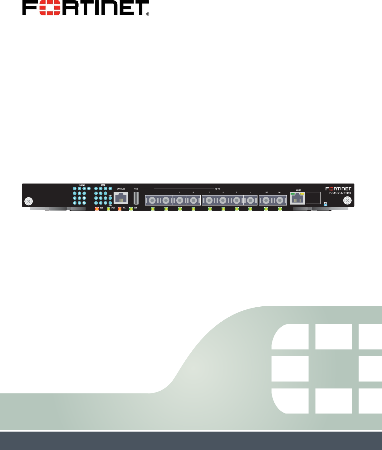
FortiController-5103B
Session-Aware Load Balancer Guide
FortiController-5103B Session-Aware Load
Balancer Guide
10-500-161552-20140822

FortiController-5103B Session-Aware Load Balancer Guide
10-500-161552-20140822
http://docs.fortinet.com/
Warnings and cautions
Only trained and qualified personnel should be allowed to install or maintain
FortiGate-5000 series equipment. Read and comply with all warnings, cautions and
notices in this document.
• Risk of Explosion if Battery is replaced by an Incorrect Type. Dispose of Used
Batteries According to the Instructions.
• Turning off all power switches may not turn off all power to the FortiGate-5000 series
equipment. Some circuitry in the FortiGate-5000 series equipment may continue to
operate even though all power switches are off.
• FortiGate-5000 equipment must be protected by a readily accessible disconnect
device or circuit breaker that can be used for product power down emergencies.
• Many FortiGate-5000 components are hot swappable and can be installed or
removed while the power is on. But some of the procedures in this document may
require power to be turned off and completely disconnected. Follow all instructions in
the procedures in this document that describe disconnecting FortiGate-5000 series
equipment from power sources, telecommunications links and networks before
installing, or removing FortiGate-5000 series components, or performing other
maintenance tasks. Failure to follow the instructions in this document can result in
personal injury or equipment damage.
• Install FortiGate-5000 series chassis at the lower positions of a rack to avoid making
the rack top-heavy and unstable.
• Do not insert metal objects or tools into open chassis slots.
• Electrostatic discharge (ESD) can damage FortiGate-5000 series equipment. Only
perform the procedures described in this document from an ESD workstation. If no
such station is available, you can provide some ESD protection by wearing an
anti-static wrist strap and attaching it to an available ESD connector such as the ESD
sockets provided on FortiGate-5000 series chassis.
• Make sure all FortiGate-5000 series components have reliable grounding. Fortinet
recommends direct connections to the building ground.
• If you install a FortiGate-5000 series component in a closed or multi-unit rack
assembly, the operating ambient temperature of the rack environment may be greater
than room ambient. Make sure the operating ambient temperature does not exceed
Fortinet’s maximum rated ambient temperature.
• Installing FortiGate-5000 series equipment in a rack should be such that the amount
of airflow required for safe operation of the equipment is not compromised.
• FortiGate-5000 series chassis should be installed by a qualified electrician.
• FortiGate-5000 series equipment shall be installed and connected to an electrical
supply source in accordance with the applicable codes and regulations for the
location in which it is installed. Particular attention shall be paid to use of correct wire
type and size to comply with the applicable codes and regulations for the installation /
location. Connection of the supply wiring to the terminal block on the equipment may
be accomplished using Listed wire compression lugs, for example, Pressure Terminal
Connector made by Ideal Industries Inc. or equivalent which is suitable for AWG-10.
Particular attention shall be given to use of the appropriate compression tool specified
by the compression lug manufacturer, if one is specified.
• This product is only intended for use in a Restricted Access Location.

FortiController-5103B Session-Aware Load Balancer Guide
10-500-161552-20140822 3
http://docs.fortinet.com/
FortiController-5103B
Contents
Warnings and cautions . . . . . . . . . . . . . . . . . . . . . . . . . . . . . . . . . . 2
FortiController-5103B system 5
Physical description . . . . . . . . . . . . . . . . . . . . . . . . . . . . . . . . . . . 6
Front panel LEDs and connectors . . . . . . . . . . . . . . . . . . . . . . . . . . . . 7
LEDs . . . . . . . . . . . . . . . . . . . . . . . . . . . . . . . . . . . . . . . . . 7
About the SH1 and SH2 LEDs . . . . . . . . . . . . . . . . . . . . . . . . . . . . 9
Front panel connectors . . . . . . . . . . . . . . . . . . . . . . . . . . . . . . . 9
FortiController-5103B session-aware load balancing . . . . . . . . . . . . . . . . . 10
Setting up a session-aware load balanced cluster . . . . . . . . . . . . . . . . 11
Configuring and managing the load balanced cluster . . . . . . . . . . . . . . . 12
Adding a second FortiController-5103B board . . . . . . . . . . . . . . . . . . 13
Adding a second Chassis . . . . . . . . . . . . . . . . . . . . . . . . . . . . . 14
Hardware installation 15
Installing SFP+ transceivers . . . . . . . . . . . . . . . . . . . . . . . . . . . . . . 15
FortiController-5103B mounting components . . . . . . . . . . . . . . . . . . . . . 16
Inserting a FortiController-5103B board . . . . . . . . . . . . . . . . . . . . . . . . 17
Shutting down and Removing a FortiController-5103B board . . . . . . . . . . . . . 19
Resetting a FortiController-5103B board. . . . . . . . . . . . . . . . . . . . . . . . 21
Troubleshooting . . . . . . . . . . . . . . . . . . . . . . . . . . . . . . . . . . . . 22
FortiController-5103B does not startup . . . . . . . . . . . . . . . . . . . . . . 22
FortiController-5103B status LED is flashing during system operation . . . . . . 22
Basic Configuration 23
Connecting to the FortiController-5103B Web-based manager (GUI) . . . . . . . . . 24
Connecting to the FortiController-5103B command line interface (CLI) . . . . . . . . 24
Factory default settings . . . . . . . . . . . . . . . . . . . . . . . . . . . . . . . . 25
Initial session-aware load balanced cluster setup . . . . . . . . . . . . . . . . . . . 25
Upgrading cluster firmware. . . . . . . . . . . . . . . . . . . . . . . . . . . . . . . 28
Verifying the configuration and the status of the boards in the cluster . . . . . . . . 28
For more information 30
Training Services . . . . . . . . . . . . . . . . . . . . . . . . . . . . . . . . . . . . 30
Technical Documentation . . . . . . . . . . . . . . . . . . . . . . . . . . . . . . . 30
Comments on Fortinet technical documentation . . . . . . . . . . . . . . . . . . . 30
Customer service and support . . . . . . . . . . . . . . . . . . . . . . . . . . . . . 30

Contents
FortiController-5103B Session-Aware Load Balancer Guide
410-500-161552-20140822
http://docs.fortinet.com/
Fortinet products End User License Agreement . . . . . . . . . . . . . . . . . . . . 30
Regulatory Notices . . . . . . . . . . . . . . . . . . . . . . . . . . . . . . . . . . . 32
Federal Communication Commission (FCC) – USA . . . . . . . . . . . . . . . . 32
Industry Canada Equipment Standard for Digital Equipment (ICES) – Canada . . 32
Voluntary Control Council for Interference (VCCI) – Japan . . . . . . . . . . . . 32
Bureau of Standards Metrology and Inspection (BSMI) – Taiwan . . . . . . . . . 32
China . . . . . . . . . . . . . . . . . . . . . . . . . . . . . . . . . . . . . . . . 32
European Conformity (CE) - EU . . . . . . . . . . . . . . . . . . . . . . . . . . 32

FortiController-5103B Session-Aware Load Balancer Guide
10-500-161552-20140822 5
http://docs.fortinet.com/
FortiController-5103B
FortiController-5103B system
The FortiController-5103B board is an Advanced Telecommunications Computing
Architecture (ATCA) compliant session-aware load balancing hub/switch board that
distributes IPv4 TCP and UDP sessions to multiple FortiGate-5000-series boards (called
workers) over the ATCA chassis fabric backplane. The FortiController-5103B board forms
a session-aware load balanced cluster with up to 12 FortiGate-5000 boards operating as
workers and uses FortiASIC DP processors to load balance millions of sessions to the
cluster, providing 10 Gbps of traffic to each cluster member. Performance of the cluster
shows linear improvement if more workers are added.
Clusters can be formed with one or two FortiController-5103B boards and up to 12
workers. All of the workers must be the same model. Currently FortiGate-5001B,
FortiGate-5001C, FortiGate-5101C, and FortiGate-5001D models are supported.
The FortiController-5103B board can be installed in any ATCA chassis that can provide
sufficient power and cooling. Supported FortiGate chassis include the 14-slot
FortiGate-5140B and the 6-slot FortiGate-5060 chassis.
You can also install the FortiController-5103B board in a FortiGate-5144C chassis but
this is not recommended because the 5144C chassis has a 40Gbit fabric backplane while
the FortiController-5103B only supports 10Gbit fabric backplane connections. Older
FortiGate-5000 chassis do not supply the power and cooling required for the
FortiController-5103B board.
In all ATCA chassis, FortiController-5103B boards are installed in the first and second
hub/switch slots (usually slots 1 and 2). A single FortiController-5103B board should be
installed in slot 1 (but you can install it in slot 2). If you add a second board it should be
installed in slot 2.
Figure 1: FortiController-5103B front panel
Two FortiController-5103B boards can be installed in an active-passive HA configuration
that provides session failover protection. Two FortiController-5103B boards can also be
installed in the same chassis in dual FortiController mode doubling the amount of
network interfaces. The FortiController-5103B board in slot 1 always becomes the
primary board and the one in slot 2 becomes the backup.
Base Network
Activity LEDs
Fabric Network
Activity LEDs
Extraction
Lever
Retention
Screw
Extraction
Lever
Retention
Screw
OOS
LED
STA
LED
PWR
LED
ACC
LED
1 to 8 10 Gig
SFP+ Network
Interfaces
B1 and B2
10 Gig Base Channel
SFP+ Interfaces
(heartbeat and
management)
MGMT
10/100/1000 Copper
Management Interface
RJ-45
Console
IPM
LED
(board
position)

Physical description FortiController-5103B system
FortiController-5103B Session-Aware Load Balancer Guide
610-500-161552-20140822
http://docs.fortinet.com/
You can also install FortiController-5103B boards in a second chassis with another set of
workers to provide chassis failover protection. In an active-passive HA configuration you
can install one or two FortiController-5103B boards in each chassis. In dual
FortiController-5103B configuration, each chassis has two FortiController-5103B boards.
The FortiController-5103B board includes the following hardware features:
• One 1-gigabit base backplane channel for layer-2 base backplane switching between
FortiGate-5000 boards installed in the same chassis as the FortiController-5103B
board. This base backplane channel includes 13 1-gigabit connections to up to 13
other slots in the chassis (slots 2 to 14).
• One 10-gigabit fabric backplane channel for layer-2 fabric backplane switching
between FortiGate-5000 boards installed in the same chassis as the
FortiController-5103B board. This fabric backplane channel includes 13 10-gigabit
connections to up to 13 other slots in the chassis (slots 2 to 14).
• Eight front panel 10-gigabit SFP+ FortiGate interfaces (1 to 8). In a session-aware load
balanced cluster these interfaces are connected to 10-gigabit networks to distribute
sessions to FortiGate-5000 boards installed in chassis slots 3 to 14. These interfaces
can also be configured to operate as 1-gigabit SFP interfaces to be connected to
1-gigabit networks.
• Two front panel base backplane 10-gigabit SFP+ interfaces (B1 and B2) that connect
to the base backplane channel. These interfaces are used for heartbeat and
management communication between FortiController-5103B boards. These
interfaces can also be configured to operate as 1-gigabit SFP interfaces.
• On-board FortiASIC DP processors to provide high-capacity session-aware load
balancing.
• One 1-gigabit out of band management ethernet interface (MGMT).
• One RJ-45, RS-232 serial console connection (CONSOLE).
• Mounting hardware.
• LED status indicators.
Physical description
Table 1: FortiController-5103B board physical description
Weight 7.2 lb. (3.23 kg)
Operating Temperature 32 to 104°F (0 to 40°C)
Storage Temperature -13 to 158°F (-35 to 70°C)
Relative Humidity 5 to 90% (Non-condensing)
Power consumption Maximum: 255 WDC; Average: 213 WDC
Max Current 5.3 A
Heat Dissipation 754 BTU/hr
FortiController-5103B system Front panel LEDs and connectors
FortiController-5103B Session-Aware Load Balancer Guide
10-500-161552-20140822 7
http://docs.fortinet.com/
Front panel LEDs and connectors
From the FortiController-5103B font panel you can view the status of the board LEDs to
verify that the board is functioning normally. You also connect the FortiController-5103B
board to your 10-gigabit network using the 1 to 8 front panel SFP+ connectors. The front
panel also includes B1 and B2 connectors for the base channels, an Ethernet
management interface (MGMT), an RJ-45 console port for connecting to the
FortiController-5103B CLI and a USB port. The USB port can be used with any USB key
for backing up and restoring configuration files.
LEDs
FortiController-5103B front panel interfaces F1 to F8 appear on the
FortiController-5103B web-based manager and CLI as interfaces f1 to f8. In single
FortiController-5103B mode, workers see these as fctrl/1 to fctrl/8. In dual
FortiController-5103B mode, workers see these as fctrl1/1 to fctrl1/8 and fctrl2/1 to
fctrl2/8.
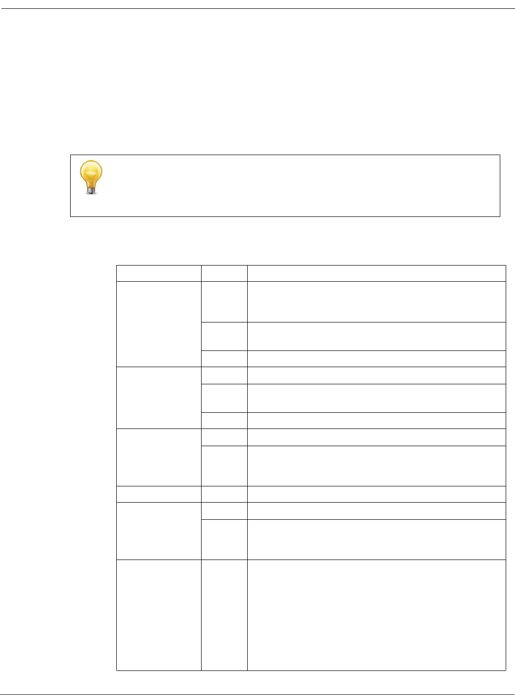
Table 2: FortiController-5103B LEDs
LED State Description
Fabric
(1/2 to 14)
Green Fabric backplane interface is connected at 10 Gbps or 1
Gbps. Backplane Fabric interface slot-14 is not
accessible.
Flashing
Green
Network activity at the fabric backplane interface.
Off No link is established.
Base (1/2 to 14)
Green Base backplane interface is connected at 1 Gbps.
Flashing
Green
Network activity at the base backplane interface.
Off No link is established.
OOS
(Out of Service)
Off Normal operation.
Amber A fault condition exists and the FortiController-5103B
blade is out of service (OOS). This LED may also flash
very briefly during normal startup.
PWR (Power) Green The FortiController-5103B board is powered on.
STA (Status)
Off The FortiController-5103B board is powered on.
Flashing
Green
The FortiController-5103B is starting up. If this LED is
flashing at any time other than system startup, a fault
condition may exist.
ACC (Disk
activity)
Off or
Flashing
green
The ACC LED flashes green when the
FortiController-5103B board accesses the flash disk. The
flash disk stores the current firmware build and
configuration files. The system accesses the flash disk
when starting up, during a firmware upgrade, or when an
administrator is using the CLI or GUI to change the
FortiController-5103B configuration. Under normal
operating conditions this LED flashes occasionally, but is
mostly off.
Front panel LEDs and connectors FortiController-5103B system
FortiController-5103B Session-Aware Load Balancer Guide
810-500-161552-20140822
http://docs.fortinet.com/
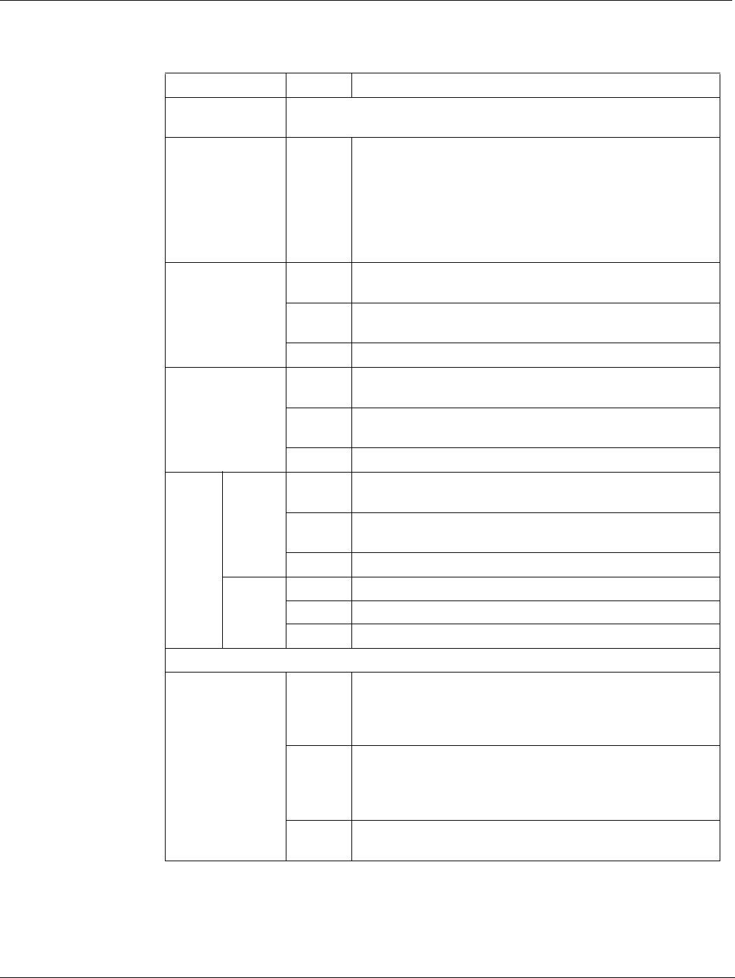
SH1 Not used in the default configuration. See “About the SH1 and SH2
LEDs” on page 9.
SH2
Green or
Flashing
Green
Network activity between the FortiController-5103B
board and one of the shelf managers across the chassis
backplane. If the FortiController-5103B board is installed
in chassis slot 1, this LED indicates a connection to shelf
manager 2. If the FortiController-5103B board is installed
in chassis slot 2, this LED indicates a connection to shelf
manager 1.
1 to 8
Green The correct cable is connected to the interface and the
connected equipment has power.
Flashing
Green
Network activity at the interface.
Off No link is established.
B1 and B2
Green The correct cable is connected to the interface and the
connected equipment has power.
Flashing
Green
Network activity at the interface.
Off No link is established.
MGMT
Link/Act
(Left
LED)
Solid
Green
Indicates this interface is connected with the correct
cable and the attached network device has power.
Blinking
Green
Indicates network traffic on this interface.
Off No Link
Speed
(Right
LED)
Green Connection at 1 Gbps.
Amber Connection at 100 Mbps.
Off Connection at 10 Mbps.
The unlabeled interface beside the MGMT interface is not used.
IPM
Blue The FortiController-5103B is ready to be hot-swapped
(removed from the chassis). If the IPM light is blue and no
other LEDs are lit the FortiController-5103B board has
lost power
Flashing
Blue
The FortiController-5103B is changing from hot swap to
running mode or from running mode to hot swap. This
happens when the FortiController-5103B board is starting
up or shutting down.
Off Normal operation. The FortiController-5103B board is in
contact with the chassis backplane.
Table 2: FortiController-5103B LEDs (Continued)
LED State Description

FortiController-5103B system Front panel LEDs and connectors
FortiController-5103B Session-Aware Load Balancer Guide
10-500-161552-20140822 9
http://docs.fortinet.com/
About the SH1 and SH2 LEDs
SH1 and SH2 are base channel interfaces that can be used to connect the
FortiController-5103B board to the chassis shelf managers over the chassis backplane.
The SH1 and SH2 LEDs indicate the status of the connections between the
FortiController-5103B board and a shelf manager. Whether or not these LEDs are lit
depends on the configuration of the SH1 and SH2 interfaces on the
FortiController-5103B board, the configuration of the chassis backplane, and if one or
both shelf managers are installed and configured to connect using the backplane or their
front panel Ethernet interfaces.
By default the SH1 interface is disabled so the SH1 LED will not light.
By default, the SH2 interface is enabled so the SH2 LED will be lit if it can connect to a
shelf manager over the chassis blackplane. If the FortiController-5103B board is installed
in chassis slot 1, the SH2 LED indicates a connection to shelf manager 2. If the
FortiController-5103B board is installed in chassis slot 2, the SH2 LED indicates a
connection to shelf manager 1.
Front panel connectors
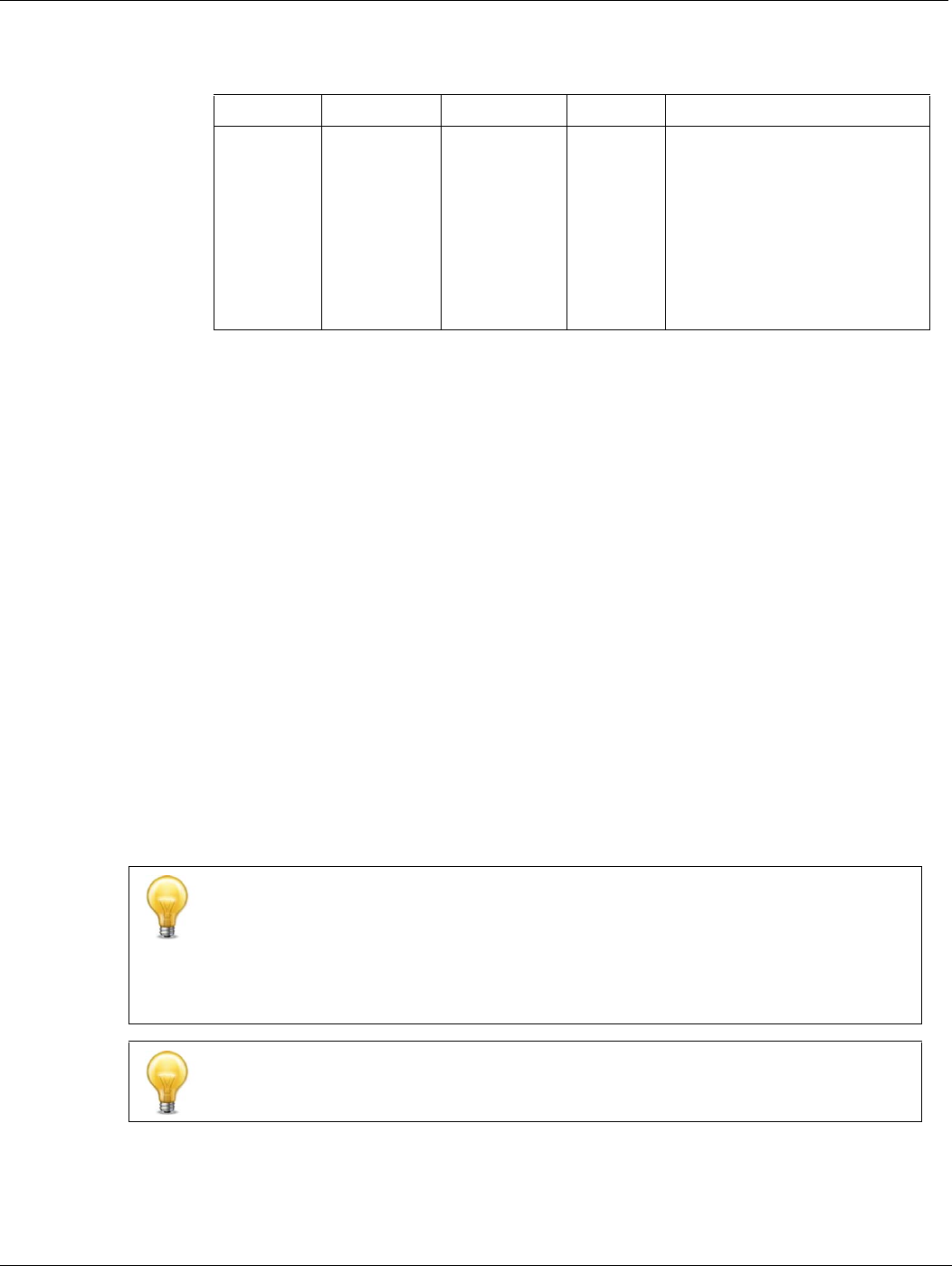
Table 3: FortiController-5103B connectors
Connector Type Speed Protocol Description
CONSOLE RJ-45 9600 bps
8/N/1
RS-232
serial
Serial connection to the
command line interface.
USB USB Not used.
1 to 8
SFP+ (10
gigabit) or
SPF (1
gigabit)
10-gigabit full
1-gigabit
auto
1-gigabit full
Ethernet 10-gigabit SPF+ connection to
10-gigabit networks or 1-
gigabit SPF connection to
1-gigabit networks. Small
form-factor pluggable
transceiver. On the
FortiController-5103B GUI and
CLI these interfaces are f1 to
f8. In single
FortiController-5103B mode,
workers see these as fctrl/1 to
fctrl/8. In dual
FortiController-5103B mode,
workers see these as fctrl1/1
to fctrl1/8 and fctrl2/1 to
fctrl2/8.
B1 and B2
SFP+ (10
gigabit) or
SPF (1
gigabit)
10-gigabit full
1-gigabit
auto
1-gigabit full
Ethernet 10-gigabit SPF+ connection to
10-gigabit networks or 1-
gigabit SPF connection to
1-gigabit networks. Small
form-factor pluggable
transceiver. For heartbeat and
management communication
between FortiController-5103B
boards.
FortiController-5103B session-aware load balancing FortiController-5103B system
FortiController-5103B Session-Aware Load Balancer Guide
10 10-500-161552-20140822
http://docs.fortinet.com/
FortiController-5103B session-aware load balancing
The FortiController-5103B board uses three on-board FortiASIC DP processors to
perform high-performance session-aware load balancing. Under ideal conditions, the
FortiController-5103B is capable of forming a session-aware load balanced cluster of one
FortiController-5103B board and up to 12 FortiGate-5000 workers. A single
FortiController-5103B board can distribute up to 96 million concurrent sessions and start
36 million new sessions a second. A second FortiController-5103B board can be added
for redundancy or to create a dual-mode cluster that doubles the number of network
interfaces. You can also install a second chassis with one or two FortiController-5103B
boards for chassis failover.
As a session-aware load balancer, the FortiController-5103B board maintains the state
for each session and is capable of directing any session to any worker installed in the
same chassis. This session-awareness means that all traffic being processed by a
specific worker continues to be processed by the same worker. Session-awareness also
means that more complex networking features such as network address translation
(NAT), fragmented packets, complex UDP protocols, and complex protocols such as SIP
that use pinholes, can be load balanced by the cluster.
In a FortiController-5103B load balanced cluster, when a worker that is processing SIP
traffic creates a pinhole, this information is communicated to the FortiController-5103B.
The FortiController-5103B then knows to distribute the voice and media sessions to this
worker.
MGMT
RJ-45 10/100/1000
Base-T
Ethernet Copper 1-gigabit connection
to 10/100/1000Base-T copper
networks for management or
system administration. The
unlabeled interface beside the
MGMT interface is not used.
Its LEDs may be lit in some
cases but the stat of these
LEDs can be ignored.
Table 3: FortiController-5103B connectors
Connector Type Speed Protocol Description
The SIP protocol uses known SIP ports for control traffic but dynamically uses a wide
range of ports for voice and other media traffic. To successfully pass SIP traffic through
a firewall, the firewall must use a session helper or application gateway to look inside the
SIP control traffic and determine the ports to open for voice and media. To allow the
voice and media traffic, the firewall temporarily opens these ports, creating what’s
known as a pinhole that temporarily allows traffic on a port as determined by the SIP
control traffic. The pinhole is closed when the voice or media session ends.
Session-aware load balancing does not support traffic shaping.

FortiController-5103B system FortiController-5103B session-aware load balancing
FortiController-5103B Session-Aware Load Balancer Guide
10-500-161552-20140822 11
http://docs.fortinet.com/
Setting up a session-aware load balanced cluster
A FortiController-5103B cluster consists of one or two FortiController-5103B boards and
up to 12 FortiGate-5000 boards. To form a cluster you must install the
FortiController-5103B board in chassis slot 1, optionally install a second
FortiController-5103B board in chassis slot 2, and select the chassis slots that will
contain workers that will join the cluster.
You then install the FortiGate-5000 workers and set them to forticontroller mode. The
boards find each other in the chassis and form a cluster. The FortiGate-5000 board with
the lowest slot number becomes the primary worker and the others become subordinate
workers.
You connect the FortiController-5103B 1 to 8 front panel interfaces to networks such as
the Internet or various internal networks. The workers see these interfaces are named
fctrl/f1 to fctrl/f8.
The FortiController-5103B load balances all sessions among all of the FortiGate-5000
boards in the cluster except IPsec VPN, SSL VPN, and routing sessions, which are
handled by the primary worker.
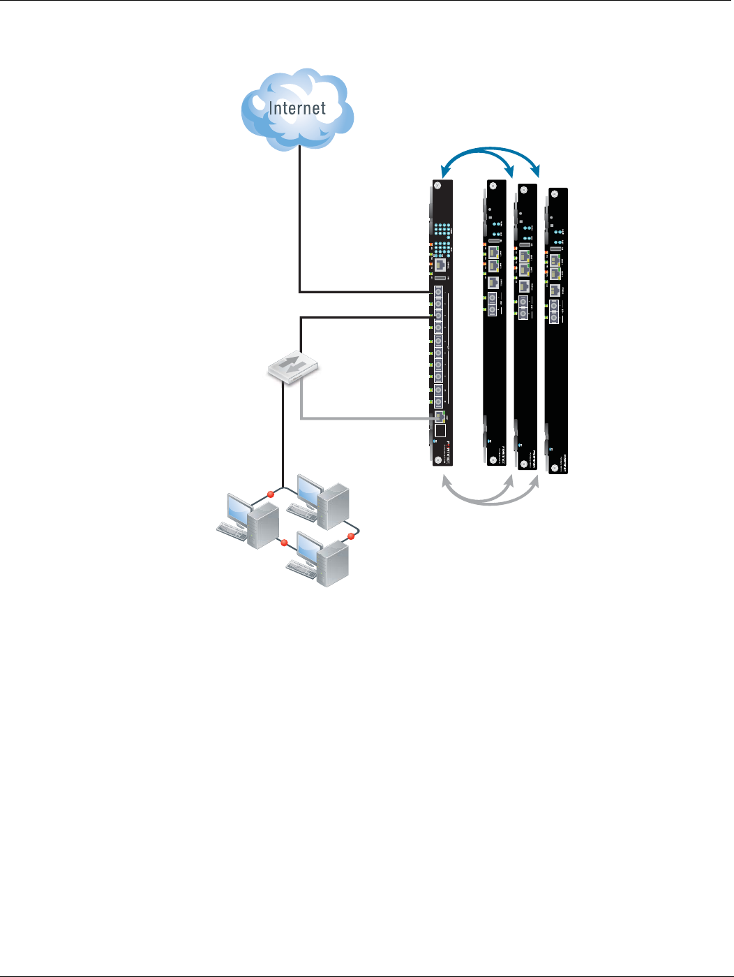
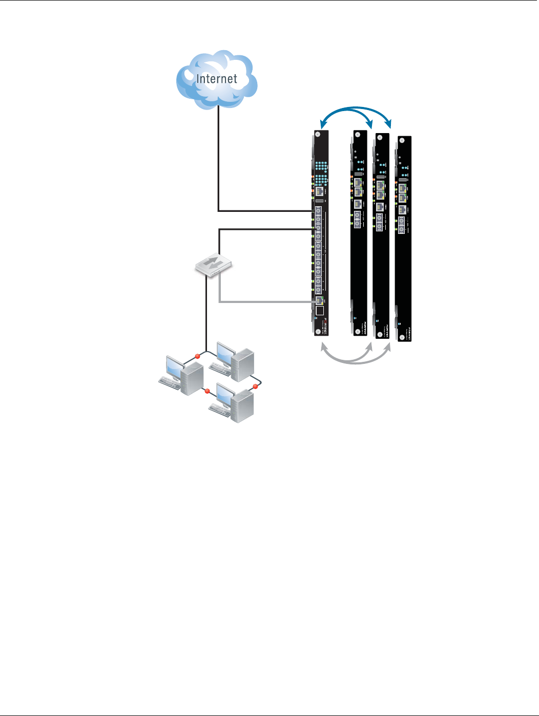
Figure 2 shows a FortiController-5103B cluster consisting of one FortiController-5103B
and three FortiGate-5001C boards. FortiController-5103B front panel interface 1 (fctrl/f1)
is connected to the Internet and front panel interface 3 (fctrl/f3) is connected to an
internal network.
FortiController-5103B session-aware load balancing FortiController-5103B system
FortiController-5103B Session-Aware Load Balancer Guide
12 10-500-161552-20140822
http://docs.fortinet.com/
Figure 2: Example FortiController-5103B load balanced cluster
Configuring and managing the load balanced cluster
You configure the cluster by logging into the FortiController-5103B web-based manager
or CLI using its mgmt port. From here you can configure and External Management
Address for the cluster. You can use this management address to log into and configure
the primary worker. All configuration changes made to the primary worker are
synchronized to the other workers.
If the External Management IP address is 10.10.10.1 you can browse to
https://10.10.10.1 to connect to the primary worker web-based manager. You can
connect to the primary worker CLI using ssh admin@10.10.10.1, or
telnet 10.10.10.1.
You can also use the External Management IP address to connect to all of the individual
boards in a chassis just by varying the custom port number that you add to the address.
The custom port number begins with the standard port number for the protocol you are
using and is followed by the chassis slot number. For example:
• To connect with a web browser to the FortiController-5103B board in slot 1 browse to
https://10.10.10.1:44301
• To connect with a web browser to the worker in slot 4 browse to
https://10.10.10.1:44304
FortiGate
Worker Boards
Slots 3 to 14
Load Balanced Traffic
on Fabric Backplane
Management and
Control Traffic on
Base Backplane
Single
FortiController
Slot 1
Internal network
Management
(mgmt)
fctrl/f1
fctrl /f3
FortiController-5103B system FortiController-5103B session-aware load balancing
FortiController-5103B Session-Aware Load Balancer Guide
10-500-161552-20140822 13
http://docs.fortinet.com/
• If HTTP administrative access is enabled, to connect with a web browser to the
worker in slot 3 browse to http://10.10.10.1:8003
• To connect using SSH to the worker in slot 8 enter a command similar to
ssh admin@10.10.10.1 -p2208
• To connect using telnet to the worker in slot 5 enter a command similar to telnet
10.10.10.1 2305
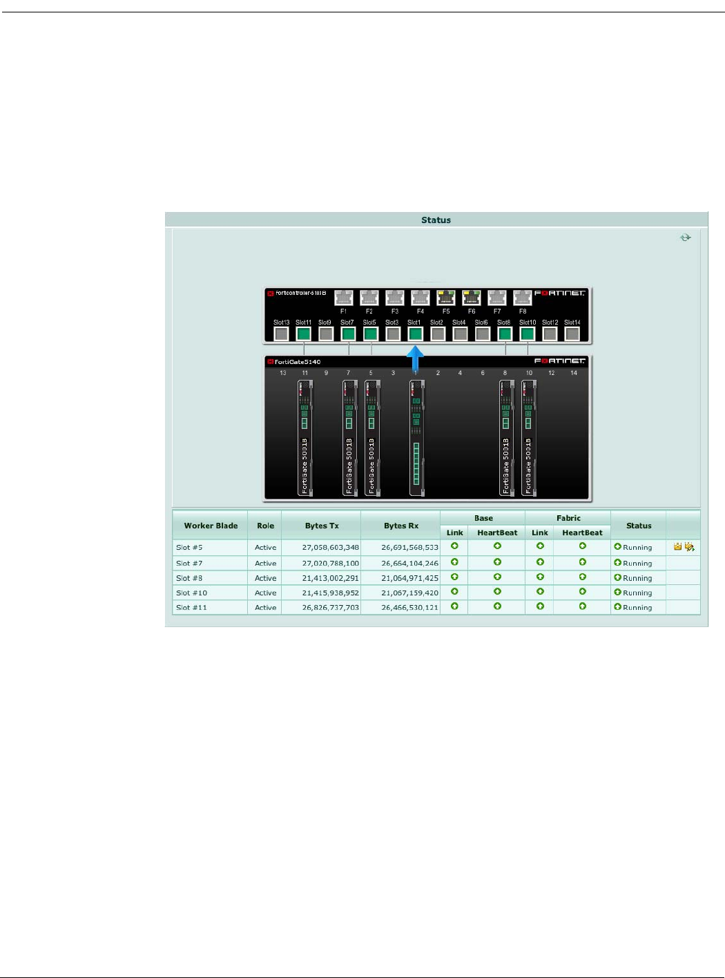
Figure 3: Example session-aware load balanced cluster status
The FortiController-5103B board supports adding and removing workers from the cluster.
So you can start with a small number of FortiGate-5000 boards and add more as your
requirements grow. When a new worker is added to a chassis, switched to forticontroller
mode, and added to the FortiController-5103B configuration, the cluster automatically
detects it, synchronizes its configuration and begins sending new sessions to it,
maintaining existing sessions on the workers that were already in the cluster. If a worker
fails or is removed from the cluster, the FortiController-5103B detects its absence and re-
balances and redistributes sessions to the remaining workers.
FortiController-5103B firmware upgrades are done from the FortiController-5103B
web-based manager or CLI. Worker firmware upgrades are done from the primary unit
web-based manager or CLI by uploading a single firmware image which is synchronized
to all of the FortiGate boards.
Adding a second FortiController-5103B board
Two FortiController-5103B boards in the same chassis can operate in two modes:

FortiController-5103B session-aware load balancing FortiController-5103B system
FortiController-5103B Session-Aware Load Balancer Guide
14 10-500-161552-20140822
http://docs.fortinet.com/
• Active passive HA configuration where the primary FortiController-5103B board is
processing traffic and the subordinate FortiController-5103B board is in hot standby
mode. Sessions are synchronized between the FortiController-5103B boards and if
the primary fails all sessions are taken up by the subordinate with minimal disruption.
• Dual FortiController mode where both FortiController-5103B boards are processing
traffic and load balancing it to all the workers. The FortiController-5103B board in
slot1 is the primary FortiController-5103B board for management purposes, but the
F1 to F8 ports on both FortiController-5103B boards are active. The workers show 16
interfaces named fctrl1/f1 to fctrl1/f8 and fctrl2/f1 to fctrl2/f8.
Adding a second Chassis
You can also add a second chassis for chassis failover. Chassis failover is supported for
active-passive HA and dual mode configurations. A dual-chassis active-passive HA
configuration can involved one or two FortiController-5103B boards in each chassis.
FortiController-5103B Session-Aware Load Balancer Guide
10-500-161552-20140822 15
http://docs.fortinet.com/
FortiController-5103B
Hardware installation
Before use, the FortiController-5103B board must be correctly inserted into the first or
second hub/switch slot of an Advanced Telecommunications Computing Architecture
(ATCA) chassis that can provide sufficient cooling and power as well as appropriate base
and fabric backplane connections.
This chapter describes:
•Installing SFP+ transceivers
•FortiController-5103B mounting components
•Inserting a FortiController-5103B board
•Shutting down and Removing a FortiController-5103B board
•Resetting a FortiController-5103B board
•Troubleshooting
Installing SFP+ transceivers
The FortiController-5103B board ships with two SR SFP+ transceivers that you must
install to connect the FortiController-5103B front panel fabric or base channel interfaces
to a network. The SFP+ transceivers are inserted into cage sockets numbered F1 to F8
for the fabric channel or B1 and B2 for the base channel on the FortiController-5103B
front panel. You can install the SFP+ transceivers before or after inserting the
FortiController-5103B board into a chassis.
You can install the following types of SPF+ transceivers for connectors F1 to F8:
•SFP+ SR
•SFP+ LR
To install SFP+ transceivers
To complete this procedure, you need:
• A FortiController-5103B board
• Two or more SFP+ transceivers
• An electrostatic discharge (ESD) preventive wrist or ankle strap with connection cord
1Attach the ESD wrist strap to your wrist and to an available ESD socket or wrist strap
terminal.
2Remove the caps from SFP+ cage sockets on the FortiController-5103B front panel.
FortiController-5103B boards must be protected from static discharge and physical
shock. Only handle or work with FortiController-5103B boards at a static-free
workstation. Always wear a grounded electrostatic discharge (ESD) preventive wrist
strap when handling FortiController-5103B boards.
Handling the transceivers by holding the release latch can damage the connector. Do
not force the transceivers into the cage slots. If the transceiver does not easily slide in
and click into place, it may not be aligned correctly. If this happens, remove the
transceiver, realign it and slide it in again.
FortiController-5103B mounting components Hardware installation
FortiController-5103B Session-Aware Load Balancer Guide
16 10-500-161552-20140822
http://docs.fortinet.com/
3Hold the sides of the transceiver and slide it into the cage socket until it clicks into
place.
FortiController-5103B mounting components
To install a FortiController-5103B board you slide the board into a hub/switch slot in the
front of an ATCA chassis (usually slot 1 or 2) and then use the mounting components to
lock the board into place in the slot. When locked into place and positioned correctly the
board front panel is flush with the chassis front panel. The board is also connected to the
chassis backplane.
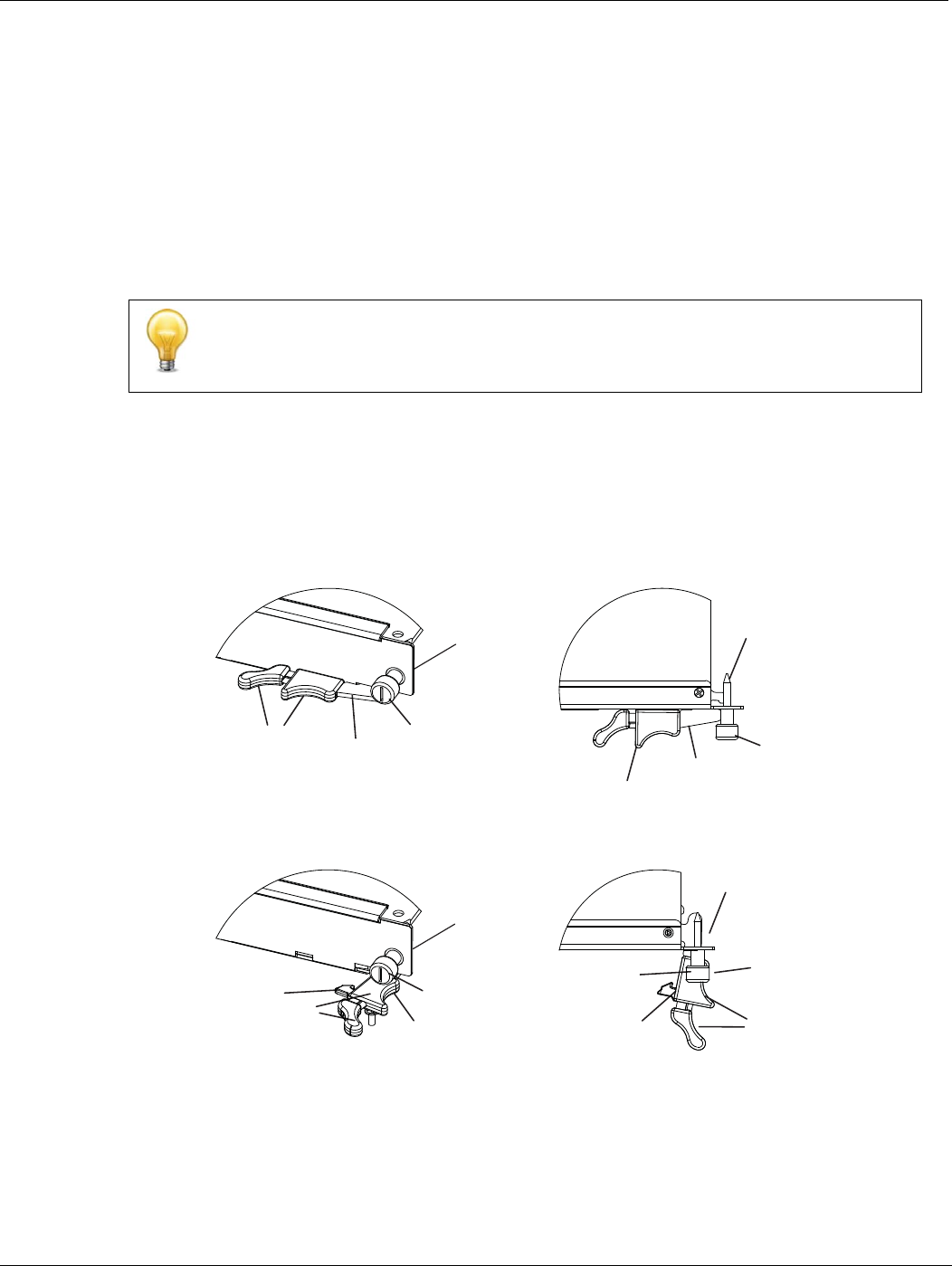
To position the board correctly you must use the mounting components shown in
Figure 4 for the right (bottom) of the FortiController-5103B front panel. The mounting
components on the left (top) of the front panel are the same but reversed. The
FortiController-5103B mounting components align the board in the chassis slot and are
used to insert and eject the board from the slot.
Figure 4: FortiController-5103B right (bottom) mounting components
FortiController-5103B boards are horizontal when inserted into a FortiGate-5060 chassis
and vertical when inserted into a FortiGate-5140-series chassis. The inserting and
removing procedures are the same in either case. For clarity the descriptions in this
document refer to the left (top) and right (bottom) mounting components.\
Closed
Open
Alignment
Pin
Retention
Screw
Lock Handle
Alignment Pin
Retention
Screw
Lock
Handle
Handle
Hook
Alignment Pin
Retention
Screw
Lock
Hook
Alignment
Pin
Retention
Screw
Lock
Handle
Hardware installation Inserting a FortiController-5103B board
FortiController-5103B Session-Aware Load Balancer Guide
10-500-161552-20140822 17
http://docs.fortinet.com/
The FortiController-5103B handles align the board in the chassis slot and are used to
insert and eject the board from the slot. The right (bottom) handle activates a microswitch
that turns on or turns off power to the board. When the right (bottom) handle is open the
microswitch is off and the board cannot receive power. When the right (bottom) handle is
fully closed the microswitch is on and if the board is fully inserted into a chassis slot the
board can receive power.
Inserting a FortiController-5103B board
The FortiController-5103B board must be fully installed in a chassis hub/switch slot
(usually slot 1 or 2), with the handles closed and locked and retention screws fully
tightened for the FortiController-5103B board to receive power and operate normally. If
the FortiController-5103B board is not receiving power, the HS LED glows solid blue and
all other LEDs remain off. See “Front panel LEDs and connectors” on page 7.
It is important to carefully seat the FortiController-5103B board all the way into the
chassis, to not use too much force on the handles, and to make sure that the handles are
properly locked. Only then will the FortiController-5103B board power-on and start up
correctly.
FortiController-5103B boards are hot swappable. The procedure for inserting
a FortiController-5103B board into a chassis slot is the same whether or not the chassis
is powered on.
To insert a FortiController-5103B board into a chassis slot
To complete this procedure, you need:
• A FortiController-5103B board
• An ATCA chassis with an empty hub/switch slot
• An electrostatic discharge (ESD) preventive wrist strap with connection cord
1Attach the ESD wrist strap to your wrist and to an ESD socket or to a bare metal
surface on the chassis or frame.
2If required, remove the protective metal frame that the FortiController-5103B board
has been shipped in.
3Insert the FortiController-5103B board into the empty hub/switch slot in the chassis.
You can reset the board without removing it from the chassis. See “Resetting a
FortiController-5103B board” on page 21.
Do not carry the FortiController-5103B board by holding the handles or retention
screws. When inserting or removing the FortiController-5103B board from a chassis slot,
handle the board by the front panel. The handles are not designed for carrying the
board. If the handles become bent or damaged the FortiController-5103B board may not
align correctly in the chassis slot.
FortiController-5103B boards must be protected from static discharge and physical
shock. Only handle or work with FortiController-5103B boards at a static-free
workstation. Always wear a grounded electrostatic discharge (ESD) preventive wrist
strap when handling FortiController-5103B boards.
Inserting a FortiController-5103B board Hardware installation
FortiController-5103B Session-Aware Load Balancer Guide
18 10-500-161552-20140822
http://docs.fortinet.com/
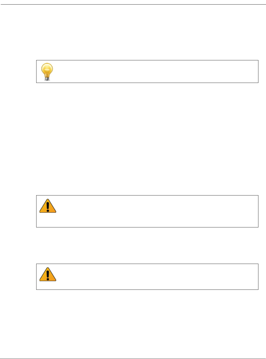
4Unlock the handles by squeezing the handle locks.
5Open the handles to their fully open positions.
6Carefully guide the board into the chassis using the rails in the slot.
Insert the board by applying moderate force to the front faceplate (not the handles) to
slide the board into the slot. The board should glide smoothly into the chassis slot. If
you encounter any resistance while sliding the board in, the board could be aligned
incorrectly. Pull the board back out and try inserting it again.
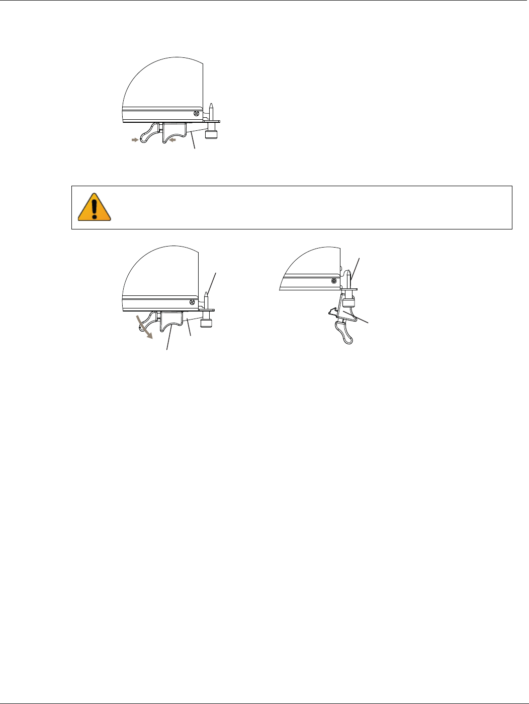
7Slide the board in until the alignment pins are inserted half way into their sockets in
the chassis.
8Turn both handles to their fully-closed positions.
The handles should hook into the sides of the chassis slot. Closing the handles draws
the FortiController-5103B board into place in the chassis slot and into full contact with
the chassis backplane. The FortiController-5103B front panel should be in contact
with the chassis front panel. When the handles are fully-closed they lock into place.
As the right (bottom) handle closes the microswitch is turned on, supplying power to
the board. If the chassis is powered on the HS LED starts flashing blue. If the board is
aligned correctly, inserted all the way into the slot, and the right (bottom) handle is
properly closed the HS LED flashes blue for a few seconds. At the same time the ACT
and HTY LEDs turn green. After a few seconds the HS LED goes out and the
FortiController-5103B firmware starts up. If the board is operating correctly, the front
panel LEDs are lit as described in Tab l e 4 .
Unlock Handle
To avoid damaging the lock, make sure you squeeze the handles fully to unlock them
before opening. The handles should pop easily out of the board front panel.
Handle
Alignment Pin
Open
Alignment Pin
Lock
Handle
Hardware installation Shutting down and Removing a FortiController-5103B board
FortiController-5103B Session-Aware Load Balancer Guide
10-500-161552-20140822 19
http://docs.fortinet.com/
If the board has not been inserted properly the HS LED changes to solid blue and all
other LEDS turn off. If this occurs, open the handles, slide the board part way out, and
repeat the insertion process.
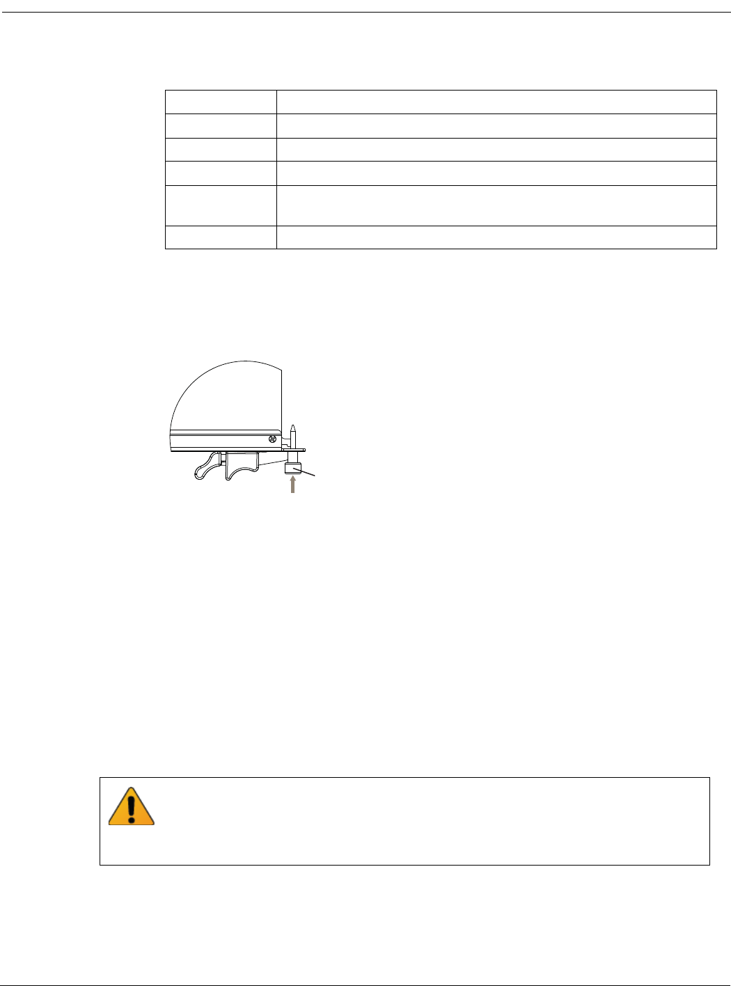
9Once the board is inserted correctly, fully tighten the retention screws to lock the
FortiController-5103B board into position in the chassis slot.
Shutting down and Removing a FortiController-5103B board
To avoid potential hardware problems, always shut down the FortiController-5103B
operating system properly before removing the FortiController-5103B board from a
chassis slot or before powering down the chassis.
The following procedure describes how to correctly use the FortiController-5103B
mounting components described in “FortiController-5103B mounting components” on
page 16 to remove a FortiController-5103B board from an ATCA chassis slot.
FortiController-5103B boards are hot swappable. The procedure for removing
a FortiController-5103B board from a chassis slot is the same whether or not the chassis
is powered on.
To remove a FortiController-5103B board from a chassis slot
To complete this procedure, you need:
• An ATCA chassis with a FortiController-5103B board installed
Table 4: FortiController-5103B normal operating LEDs
LED State
OOS Off
Power Green
Status Off
ACC Off (Or flashing green when the system accesses the
FortiController-5103B flash disk.)
IPM Off
Tighten
Retention
Screw
Do not carry the FortiController-5103B board by holding the handles or retention
screws. When inserting or removing the FortiController-5103B board from a chassis slot,
handle the board by the front panel. The handles are not designed for carrying the
board. If the handles become bent or damaged the FortiController-5103B board may not
align correctly in the chassis slot.
Shutting down and Removing a FortiController-5103B board Hardware installation
FortiController-5103B Session-Aware Load Balancer Guide
20 10-500-161552-20140822
http://docs.fortinet.com/
• An electrostatic discharge (ESD) preventive wrist strap with connection cord
1Attach the ESD wrist strap to your wrist and to an ESD socket or to a bare metal
surface on the chassis or frame.
2Disconnect all cables from the FortiController-5103B board, including all network
cables and the console cable.
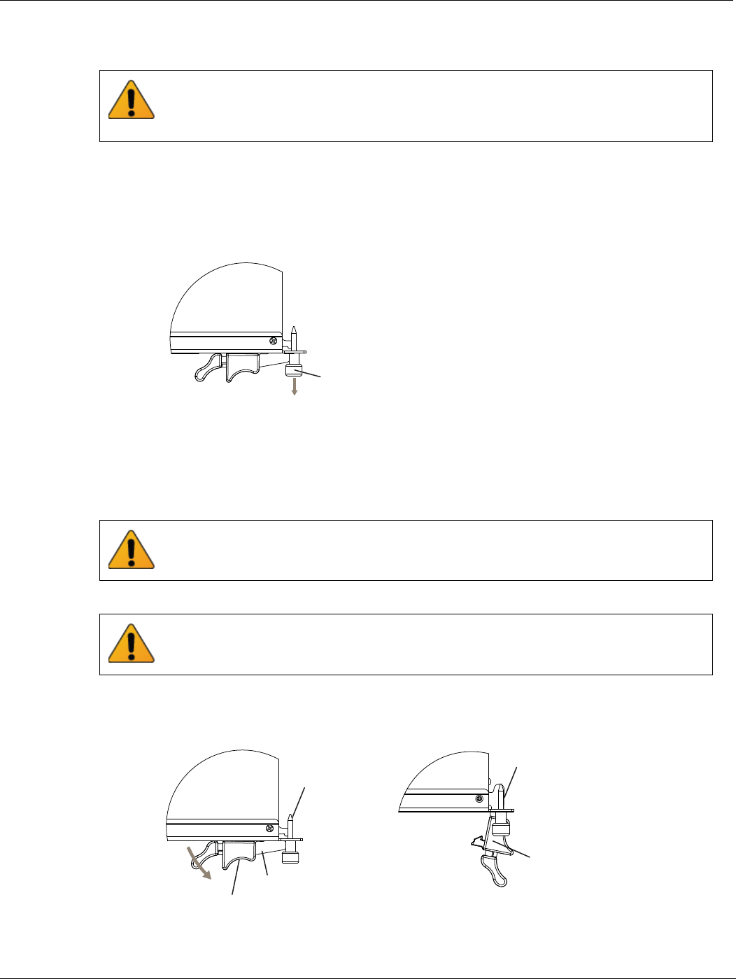
3Fully loosen the FortiController-5103B retention screws.
4Unlock the handles by squeezing the handle locks.
5Slowly open both handles a small amount (about 8 degrees) until the IPM LED flashes
blue.
6Keep the handles in this position until the IPM LED stops flashing and becomes solid
blue.
7Open the handles to their fully open positions.
Opening the handles turns off the microswitch, turns off all LEDs, and ejects the board
from the chassis slot. You need to use moderate pressure on the handles to eject the
board.
8Pull the board about half way out.
FortiController-5103B boards must be protected from static discharge and physical
shock. Only handle or work with FortiController-5103B boards at a static-free
workstation. Always wear a grounded electrostatic discharge (ESD) preventive wrist
strap when handling FortiController-5103B boards.
Loosen
Retention
Screw
Waiting for the IPM LED to change to solid blue makes sure that the board software
shutdowns completely before disconnecting it from backplane power.
To avoid damaging the lock, make sure you squeeze the handles fully to unlock them
before opening. The handles should pop easily out of the board front panel.
Handle
Alignment Pin
Open
Alignment Pin
Lock
Handle
Hardware installation Resetting a FortiController-5103B board
FortiController-5103B Session-Aware Load Balancer Guide
10-500-161552-20140822 21
http://docs.fortinet.com/
9Turn both handles to their fully-closed positions.
When the handles are fully-closed they lock into place.
10 Carefully slide the board completely out of the slot.
11 Re-attach the protective metal frame if you are going ship the FortiController-5103B
board or store it outside of a chassis.
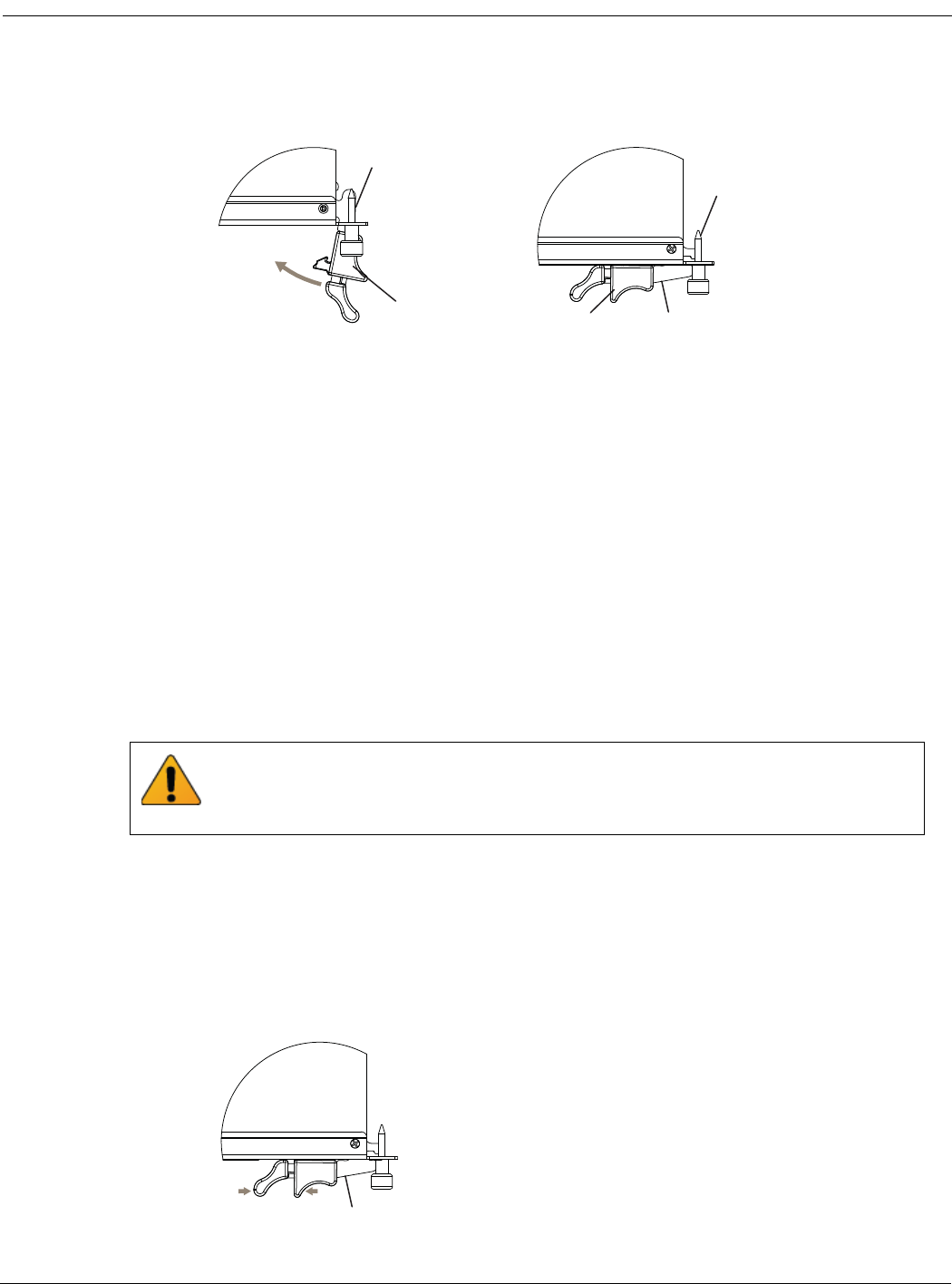
Resetting a FortiController-5103B board
You can use the following procedure to reset a FortiController-5103B board without
removing it from the chassis.
To reset a FortiController-5103B without removing the board from the chassis
You do not have to loosen the retention screws or adjust the position of the
FortiController-5103B board to use this procedure.
To complete this procedure, you need:
• An ATCA chassis with a FortiController-5103B board installed
• An electrostatic discharge (ESD) preventive wrist strap with connection cord
1Attach the ESD wrist strap to your wrist and to an ESD socket or to a bare metal
surface on the chassis or frame.
2Unlock the right handle by squeezing the handle lock.
3Pivot the right handle open.
The handle can only pivot a short distance. Pivoting the right handle turns off the
microswitch which powers down the board, turning off all LEDs except the IPM LED
which turns on.
Fully Closed
and Locked
Alignment Pin
Handle
Close
Alignment Pin
Handle
FortiController-5103B boards must be protected from static discharge and physical
shock. Only handle or work with FortiController-5103B boards at a static-free
workstation. Always wear a grounded electrostatic discharge (ESD) preventive wrist
strap when handling FortiController-5103B boards.
Unlock Handle

Troubleshooting Hardware installation
FortiController-5103B Session-Aware Load Balancer Guide
22 10-500-161552-20140822
http://docs.fortinet.com/
4After 10 seconds snap the right handle back into place.
The board powers up, the LEDs light and in a few minutes the FortiController-5103B
board operates normally.
Troubleshooting
This section describes the following troubleshooting topics:
•FortiController-5103B does not startup
FortiController-5103B does not startup
Positioning of FortiController-5103B handles and a few other causes may prevent a
FortiController-5103B board for starting up correctly.
All chassis: handles not fully closed
If the handles are damaged or positioned incorrectly the FortiController-5103B board will
not start up. Make sure the handles are correctly aligned, fully inserted and locked.
All chassis: Firmware problem
If the FortiController-5103B board is receiving power and the handles are fully closed,
and you have restarted the chassis and the FortiController-5103B still does not start up,
the problem could be with FortiOS. Connect to the FortiController-5103B console and try
cycling the power to the board. If the BIOS starts up, interrupt the BIOS startup and
install a new firmware image.
If this does not solve the problem, contact Fortinet Technical Support.
FortiController-5103B status LED is flashing during system operation
Normally, the FortiController-5103B Status LED is off when the FortiController-5103B
board is operating normally. If this LED starts flashing while the board is operating, a fault
condition may exist. At the same time the FortiController-5103B may stop processing
traffic.
To resolve the problem you can try removing and reinserting the FortiController-5103B
board in the chassis slot. Reloading the firmware may also help.
If this does not solve the problem there may have been a hardware failure or other
problem. Contact Fortinet Technical Support for assistance.

FortiController-5103B Session-Aware Load Balancer Guide
10-500-161552-20140822 23
http://docs.fortinet.com/
FortiController-5103B
Basic Configuration
This section describes the basics of connecting and configuring a session-aware load
balanced (SALB) cluster consisting of a FortiController-5103B board installed in slot 1
and 2 or more workers installed in chassis slots 3 and up.
Before using this chapter, your chassis should be mounted and connected to your power
system and the boards should be installed in the chassis. The chassis and the boards
should also be powered up and the front panel LEDs should indicate that the boards are
functioning normally.
For more information about setting up a SALB cluster, see the FortiController Session
Aware Load Balancing Guide available from the FortiGate-5000 Technical Documentation
page of the Fortinet Technical Documentation Website.
This chapter includes the following topics:
•Connecting to the FortiController-5103B Web-based manager (GUI)
•Connecting to the FortiController-5103B command line interface (CLI)
•Factory default settings
•Initial session-aware load balanced cluster setup
•Upgrading cluster firmware
•Verifying the configuration and the status of the boards in the cluster
Connecting to the FortiController-5103B Web-based manager (GUI) Basic Configuration
FortiController-5103B Session-Aware Load Balancer Guide
24 10-500-161552-20140822
http://docs.fortinet.com/
Figure 5: Example session-aware load balanced cluster
Connecting to the FortiController-5103B Web-based manager
(GUI)
You can connect to the FortiController-5103B web-based manager by browsing to the
FortiController-5103B mgmt interface IP address. From the FortiController-5103B
web-based manager you can add workers to the cluster and configure load balancing
settings.
By default, you can connect to the FortiController-5103B web-based manager by
connecting the mgmt interface to your network and browsing to https://192.168.1.99.
Connecting to the FortiController-5103B command line interface
(CLI)
You can connect to the FortiController-5103B CLI using the serial cable that came
packaged with your FortiController-5103B board or an Ethernet connection to the mgmt
interface.
FortiGate
Worker Boards
Slots 3 to 14
Load Balanced Traffic
on Fabric Backplane
Management and
Control Traffic on
Base Backplane
Single
FortiController
Slot 1
Internal network
Management
(mgmt)
fctrl/f1
fctrl /f3
Basic Configuration Factory default settings
FortiController-5103B Session-Aware Load Balancer Guide
10-500-161552-20140822 25
http://docs.fortinet.com/
To connect to the CLI over an Ethernet network use SSH to connect to the mgmt port
(default IP address 192.168.1.99).
To connect to the CLI using a serial console connection
1Connect the FortiController-5103B unit’s Console port to the serial communications
(COM) port on your management computer using a serial cable (or using an RS-232 to
USB convertor).
2Start the terminal emulation application and configure the following settings.
• Bits per second: 9600
• Data bits: 8
• Parity: None
• Stop bits: 1
• Flow control: None
3Press Enter to connect to the CLI.
4Type a valid administrator account name (such as admin) and press Enter.
5Type the password for that administrator account and press Enter. (In its default state,
there is no password for the admin account.)
Factory default settings
The FortiController-5103B unit ships with a factory default configuration. The default
configuration allows you to connect to and use the FortiController-5103B web-based
manager or CLI to configure the FortiController-5103B board.
To configure the FortiController-5103B board you should add a password for the admin
administrator account, change the management interface IP address, and, if required,
configure the default route for the management interface.
Initial session-aware load balanced cluster setup
This section describes how to setup a session-aware load balancing cluster consisting of
a single FortiGate chassis, a FortiController-5103B board, and three FortiGate-5000
workers, similar to the cluster shown in Figure 5 on page 24.
To install the FortiController-5103B board and connect to its web-based manager
1Insert the FortiController-5103B board into chassis slot 1 using the procedure
“Inserting a FortiController-5103B board” on page 17.
2Connect the FortiController-5103B mgmt interface to the network from which you
want to manage the device.
Table 5: FortiController-5103B factory default settings
Administrator Account User Name: admin
Password: (none)
MGMT IP/Netmask 192.168.1.99/24
At any time during the configuration process, if you run into problems, you can reset the
FortiController-5103B board or the FortiGate-5001B boards to factory default settings
and start over. From the CLI enter execute factory-reset.

Initial session-aware load balanced cluster setup Basic Configuration
FortiController-5103B Session-Aware Load Balancer Guide
26 10-500-161552-20140822
http://docs.fortinet.com/
3Connect the external network to FortiController-5103B front panel interface 1.
4Connect the internal network to front panel interface 3.
5From a management PC connected to the same network as the mgmt interface,
browse to https://192.168.1.99 to connect to the FortiController-5103B web-based
manager. (You can also connect to the CLI using the console port or SSH).
6Log into the FortiController-5103B web-based manager using admin with no
password.
7Check the firmware version that the FortiController-5103B is running (from the
dashboard or from the CLI using the get system status command).
8Check the FortiSwitch-ATCA release notes and confirm that your
FortiController-5103B is running the latest supported firmware. You can download the
correct firmware from Fortinet’s Support site (https://support.fortinet.com).
To install and configure the workers
1Insert workers into their chassis slots using the insertion procedure described in their
documentation.
2From the FortiController-5103B web-based manager go to Load Balance > Config.
3Add the workers to the cluster by selecting Edit and moving the slots that contain
workers to the Members list.
From the CLI you can use the following command to add slots 3, 4, and 5 to the
cluster:
config load-balance setting
config slots
edit 3
next
edit 4
next
edit 5
end
end
You can use the delete command to remove a slot from the cluster, for example to
remove slot 5 enter:
config load-balance setting
config slots
delete 5
end
end
The status of the workers will be down until you complete the following steps for each
worker.
4Connect to the worker CLI. You can use the console port or use SSH to connect to the
mgmt interface (default IP address 192.168.1.99).
Basic Configuration Initial session-aware load balanced cluster setup
FortiController-5103B Session-Aware Load Balancer Guide
10-500-161552-20140822 27
http://docs.fortinet.com/
5Enter the following command to switch the worker to load balance mode.
config system elbc
set mode forticontroller
end
The worker restarts in load balance mode and joins the cluster.
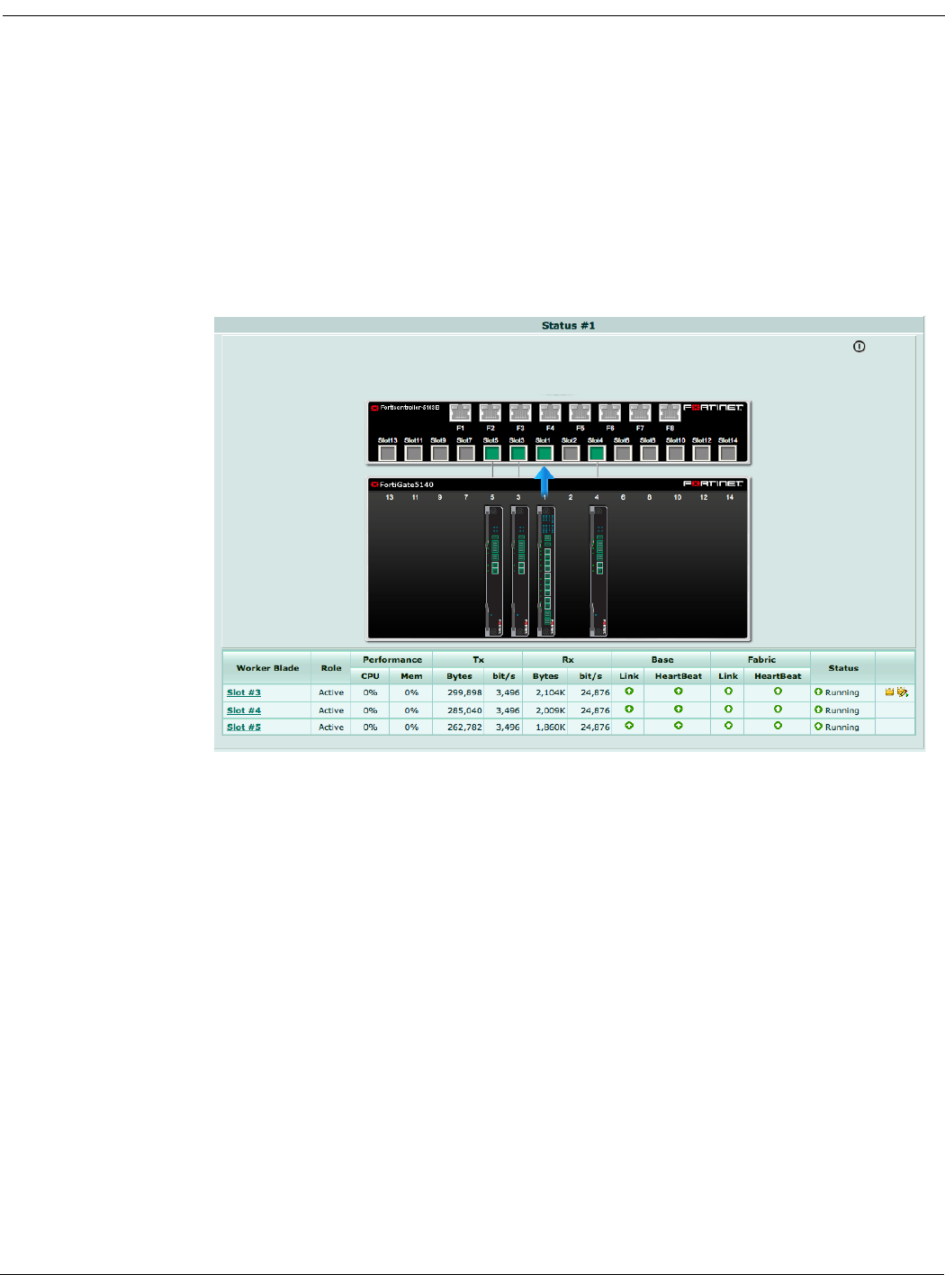
To verify that the worker has joined the cluster, from the FortiController-5103B
web-based manager and go to Load Balance > Status and verify that the worker
appears in the correct chassis slot.
Figure 6: Example FortiController-5103B status display
6Repeat these steps to add all workers to the cluster.
The worker in the lowest slot number becomes the primary unit.
7Configure the cluster external management interface so that you can manage the
worker configuration. From the FortiController-5103B GUI go to Load Balance >
Config.
8Edit the External Management IP/Netmask and change it to an IP address and
netmask for the network that the mgmt interfaces of the FortiController-5103B and the
FortiGate-5000 boards are connected to. The External Management IP/Netmask must
be on the same subnet as the FortiController-5103B management IP address.
You can now manage the workers by browsing to this External Management IP or by
logging into the FortiController-5103B GUI, going to Load Balance > Status and
selecting the Config Master icon beside the primary FortiGate-5000 unit, which is
always the top entry in the Worker Blade list.
Upgrading cluster firmware Basic Configuration
FortiController-5103B Session-Aware Load Balancer Guide
28 10-500-161552-20140822
http://docs.fortinet.com/
Upgrading cluster firmware
Fortinet periodically updates the FortiController-5103B and worker (FortiGate) firmware
to include enhancements and address issues. After you have registered the
FortiController-5103B boards and workers in your cluster you can download
FortiController-5103B and FortiOS firmware from the support web site
http://support.fortinet.com.
You upgrade the FortiController-5103B firmware from the FortiController-5103B
web-based manager or CLI. You can upgrade the worker firmware from the worker
web-based manager or CLI. The recommended procedure is to upgrade the worker first
and then upgrade the FortiController-5103B firmware.
To upgrade worker firmware from the web-based manager
This procedure upgrades the firmware running on all of the workers in the cluster in a
single operation from the worker web-based manager. The firmware running on all of the
workers in the cluster is updated simultaneously.
1Log into the worker web-based manager.
2From the Global System Information dashboard widget beside Firmware Version
select Update.
3Select the new firmware file and select OK.
The firmware image file is uploaded and verified then installed on all of the workers.
After a few minutes the cluster continues operating, the workers running the new
firmware build.
You can confirm that all of the workers are back in the cluster from the Load Balance >
Status page of the FortiController-5103B web-based manager.
To upgrade FortiController-5103B firmware from the web-based manager
If the cluster contains two FortiController-5103B boards, this procedure upgrades the
firmware running on both of them in a single operation.
1Log into the FortiController-5103B web-based manager.
2From the System Information dashboard widget beside Firmware Version select
Update.
3Select the new firmware file and select OK.
The firmware image file is uploaded and verified then installed on all of the
FortiController-5103B boards. After a few minutes the cluster continues operating.
Verifying the configuration and the status of the boards in the
cluster
Use the following command from the FortiController-5103B CLI to verify that the
FortiController-5103B board can communicate with all of the FortiGate-5001B boards in
the cluster and to show the status of each board. For example, for the cluster shown in
Figure 5 on page 24 the command output would be the following if the cluster is
operating properly:
Upgrading the firmware may briefly interrupt network traffic so it should be done during
a quiet period.

Basic Configuration Verifying the configuration and the status of the boards in the cluster
FortiController-5103B Session-Aware Load Balancer Guide
10-500-161552-20140822 29
http://docs.fortinet.com/
get load-balance status
ELBC Master Blade: slot-4
Confsync Master Blade: slot-4
Blades:
Working: 3 [ 3 Active 0 Standby]
Ready: 0 [ 0 Active 0 Standby]
Dead: 0 [ 0 Active 0 Standby]
Total: 3 [ 3 Active 0 Standby]
Slot 4: Status:Working Function:Active
Link: Base: Up Fabric: Up
Heartbeat: Managment: Good Data: Good
Status Message:"Running"
Slot 6: Status:Working Function:Active
Link: Base: Up Fabric: Up
Heartbeat: Managment: Good Data: Good
Status Message:"Running"
Slot 8: Status:Working Function:Active
Link: Base: Up Fabric: Up
Heartbeat: Managment: Good Data: Good
Status Message:"Running"
The command output provides the same information as the Load Balance > Status
web-based manager page, including the slot that contains the primary unit (slot 4), the
number of FortiGate-5001B boards in the cluster, the slots containing all of the
FortiGate-5001B boards (4, 6, and 8) and the status of each board. Status information
includes the status of the connection between the board and the base and fabric
backplanes, whether the heartbeat is active, the status of the board and the data
processed by the board. The status message can also indicate if the board is waiting for
a fabric connection or waiting for a base connection.
You can also use the following commands to display detailed session aware load
balancing diagnostics:
diangnose salb {dp | tcam-rules}
The dp option provides diagnostics for the FortiASIC DP processors and the
tcam-rules option provides diagnostics for content aware routing rules (TCAM).

FortiController-5103B Session-Aware Load Balancer Guide
10-500-161552-20140822 30
http://docs.fortinet.com/
FortiController-5103B
For more information
Training Services
Fortinet Training Services offers courses that orient you quickly to your new equipment, and certifications to verify
your knowledge level. Fortinet training programs serve the needs of Fortinet customers and partners world-wide.
Visit Fortinet Training Services at http://campus.training.fortinet.com, or email training@fortinet.com.
Technical Documentation
Visit the Fortinet Technical Documentation web site, http://docs.fortinet.com, for the most up-to-date technical
documentation.
The Fortinet Knowledge Base provides troubleshooting, how-to articles, examples, FAQs, technical notes, and
more. Visit the Fortinet Knowledge Base at http://kb.fortinet.com.
Comments on Fortinet technical documentation
Send information about any errors or omissions in this or any Fortinet technical document to
techdoc@fortinet.com.
Customer service and support
Fortinet is committed to your complete satisfaction. Through our regional Technical Assistance Centers and
partners worldwide, Fortinet provides remedial support during the operation phase of your Fortinet product's
development life cycle. Our Certified Support Partners provide first level technical assistance to Fortinet
customers, while the regional TACs solve complex technical issues that our partners are unable to resolve.
Visit Customer Service and Support at http://support.fortinet.com.
Fortinet products End User License Agreement
See the Fortinet products End User License Agreement.

For more information Fortinet products End User License Agreement
FortiController-5103B Session-Aware Load Balancer Guide
10-500-161552-20140822 31
http://docs.fortinet.com/
FortiController-5103B Session-Aware Load Balancer Guide
August 22, 2014
10-500-161552-20140822
Copyright© 2014 Fortinet, Inc. All rights reserved. Fortinet®, FortiGate®, FortiCare® and FortiGuard®, and
certain other marks are registered trademarks of Fortinet, Inc., and other Fortinet names herein may also be
registered and/or common law trademarks of Fortinet. All other product or company names may be trademarks of
their respective owners. Performance and other metrics contained herein were attained in internal lab tests under
ideal conditions, and actual performance and other results may vary. Network variables, different network
environments and other conditions may affect performance results. Nothing herein represents any binding
commitment by Fortinet, and Fortinet disclaims all warranties, whether express or implied, except to the extent
Fortinet enters a binding written contract, signed by Fortinet’s General Counsel, with a purchaser that expressly
warrants that the identified product will perform according to certain expressly-identified performance metrics
and, in such event, only the specific performance metrics expressly identified in such binding written contract
shall be binding on Fortinet. For absolute clarity, any such warranty will be limited to performance in the same
ideal conditions as in Fortinet’s internal lab tests. Fortinet disclaims in full any covenants, representations, and
guarantees pursuant hereto, whether express or implied. Fortinet reserves the right to change, modify, transfer, or
otherwise revise this publication without notice, and the most current version of the publication shall be
applicable.
Visit these links for more information and documentation for your Fortinet products:
Fortinet Knowledge Base - http://kb.fortinet.com
Technical Documentation - http://docs.fortinet.com
Training Services - http://campus.training.fortinet.com
Customer Service and Support - http://support.fortinet.com
You can report errors or omissions in this or any Fortinet technical document to techdoc@fortinet.com.
Regulatory Notices For more information
FortiController-5103B Session-Aware Load Balancer Guide
32 10-500-161552-20140822
http://docs.fortinet.com/
Regulatory Notices
Federal Communication Commission (FCC) – USA
This device complies with Part 15 of FCC Rules. Operation is subject to the following two conditions:
(1) this device may not cause harmful interference, and
(2) this device must accept any interference received; including interference that may cause undesired operation.
This equipment has been tested and found to comply with the limits for a Class A digital device, pursuant to Part
15 of the FCC Rules. These limits are designed to provide reasonable protection against harmful interference
when the equipment is operated in a commercial environment. This equipment generates, uses, and can radiate
radio frequency energy, and if it is not installed and used in accordance with the instruction manual, it may cause
harmful interference to radio communications. Operation of this equipment in a residential area is likely to cause
harmful interference, in which case the user will be required to correct the interference at his own expense.
WARNING: Any changes or modifications to this product not expressly approved by the party responsible for
compliance could void the user’s authority to operate the equipment
Industry Canada Equipment Standard for Digital Equipment (ICES) – Canada
CAN ICES-3 (A) / NMB-3 (A)
This digital apparatus does not exceed the Class A limits for radio noise emissions from digital apparatus set out
in the Radio Interference Regulations of the Canadian Department of Communications.
Le présent appareil numérique n’emet pas de bruits radioélectriques dép¬assant les limites applicables aux
appareils numeriques de la classe A préscrites dans le Règlement sur le brouillage radioélectrique édicte par le
ministère des Communications du Canada.
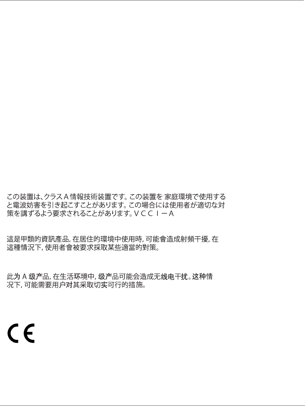
Voluntary Control Council for Interference (VCCI) – Japan
Bureau of Standards Metrology and Inspection (BSMI) – Taiwan
China
European Conformity (CE) - EU
This is a Class A product. In a domestic environment, this product may cause radio interference, in which case the
user may be required to take adequate measures.
